fuel tank / pre-pump kit - strictly diesel tank / pre-pump kit . ... recheck all fittings &...
TRANSCRIPT
Fuel Tank / Pre-Pump Kit Fits 1999-2003 7.3L Powerstroke Diesel Pickup Truck & Excursion
(not intended for use on vans)
INSTALLATION GUIDE Kit Contents

2
To familiarize yourself with the different fittings and assemblies that make up the kit, make sure that the following parts are present:
Qty Part Number Description 1 TK-06-03-HBUS 3/8” Suction Adapter Assembly 1 TK-05-290-12-HBUS 5’16” Pre-Formed Stainless Steel Return Line Assembly 1 TK-06-15 15’ of Gates LOC 3/8” 30R7 Fuel Line 2 06NC-06FJX 3/8” Push-Lok Hose Ends 2 PC10 Self Tightening Pinch Clamps 2 08MP-06MJ 1/2” Male Pipe Thread to 3/8” Male JIC Fittings 1 Head Fuel Filter Head (MADE IN THE USA!) 1 BF1212 Baldwin BF1212 Fuel Filter Element 1 Bracket Driven Diesel Stainless Steel Fuel Filter Mounting Bracket 1 Bracket Driven Diesel Stainless Steel Backing Plate 3 1/4-20 Nylok 1/4-20 Nylok Nut 3 1/4 Washer 1/4” SAE Flat Washer 3 3/8-16x4 Bolt 3/8-16 x 4” Long Bolt 6 3/8 Washer 3/8” SAE Flat Washer 3 3/8-16 Nylok 3/8-16 Nylok Nut 4 WGN06SS Stainless Steel Hose Clamps 1 WGN02SS Stainless Steel Hose Clamp Paperwork Installation Instructions, etc.
hank you for purchasing the Driven Diesel Fuel Tank /Pre-Pump Kit. Your kit should have the above-mentioned items for your installation. Please read and familiarize yourself with this manual fully before proceeding with the installation of the kit. Also, always work safely. Make
sure there is plenty of light and adequate ventilation available, and allow yourself several hours to complete the installation. Finally, the installation of this kit requires exposing the fuel system. Diesel fuel is flammable, and its vapor is explosive; therefore common sense dictates that there be no smoking or open flame within 50 feet of the workspace. If any fuel spills, contain it and clean it up immediately. Do not let any fuel stand on painted surfaces of your vehicle, or damage to the finish may result. Installation of this kit also requires accessing the fuel tank. This can be accomplished by either lowering the fuel tank from the bottom, or if installing on a truck, removing the pick-up bed. Both options require working with heavy objects in awkward positions. Make sure you have adequate help before attempting this part of the installation. You may download copies of the factory-recommended procedures for this from our website. Please understand that these are intended as illustrations only, and Driven Diesel does not assume liability for errors or omissions in these documents. We strongly recommend that you look over these instructions completely, and if you feel the installation is beyond your capability, we recommend you take this kit to a qualified mechanic to install the product.
T
3
Installation REMINDER: Be careful when installing this kit. It involves accessing the Fuel Tank, and any way you do that will involve working with heavy and awkward components. Make sure you have adequate help standing by when preparing to work with these parts. 1. To install this kit, you will need access to the top of the fuel tank. There are two ways to
accomplish this. One is to remove the tank from the bottom of the vehicle. The other is to remove the bed of the truck.
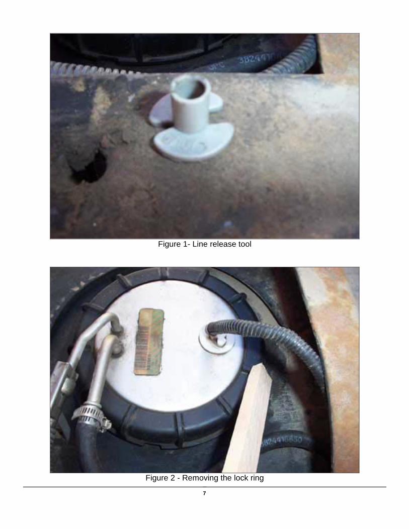
2. Depending on the year of your truck you may need to use a set of fuel line removal tools (3/8” blue and 5/16” gray – available at your local auto parts store) to disconnect the lines from the pickup assembly. (see Fig. 1)
3. Don’t forget to disconnect the wiring to the level sender before trying to remove the tank from underneath the truck.
4. Depending on your specific truck, it may be necessary to jack up the truck in order to slide the fuel tank out.
5. Using a wooden block and a hammer, gently tap the plastic ring holding the fuel pickup assembly to the top of the tank. Tap the ring so it rotates in a counter-clockwise direction (see Fig. 2). A large rubber “strap wrench” will also work well for this. TIP: Place the retainer ring in the sun and the tank in the shade; this will help with reassembly.
6. Carefully remove the fuel pickup assembly from the tank. Be sure the plastic “umbrella” comes out with the assembly. It may fall off of the assembly, requiring retrieval from the bottom of the tank.
7. NOTE: You must be careful with the float-sender assembly. It is fragile; the element is ceramic and can break very easily. It is helpful to find a way to clamp the pickup assembly in a vise or other device to hold the assembly while working on it.
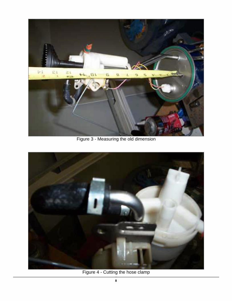
8. Before starting any modifications, carefully measure the distance between the bottom of the fuel pickup screen and the metal cap on the pickup assembly. Note this dimension, as it will be used to adjust the pickup umbrella later (see Fig. 3).
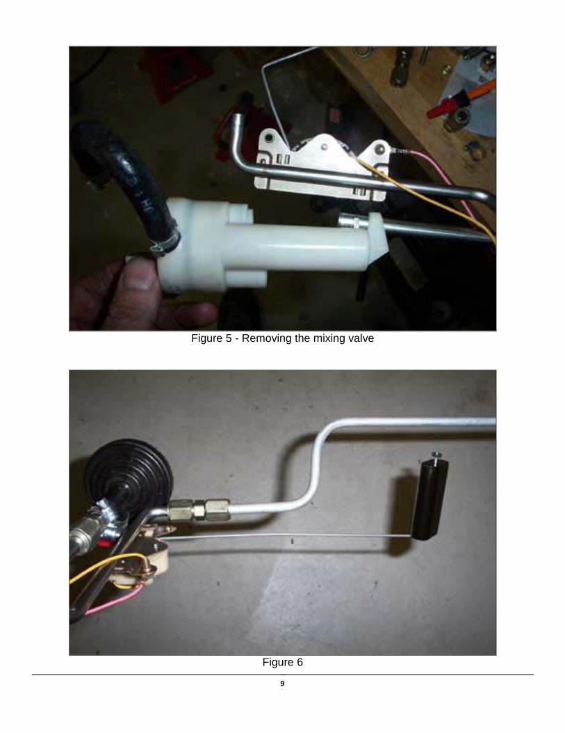
9. Remove the umbrella by sliding it off of the mixing valve. It may or may not have a clamp on it. Carefully cut the hose clamp on the return hose from the mixing valve, and remove the hose from the steel line (see Fig. 4).
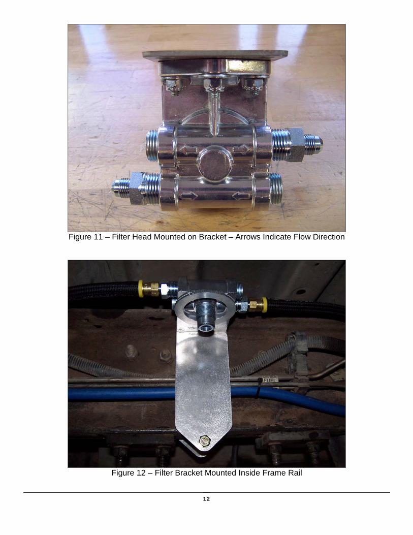
10. Now slide the mixing valve off of the fuel pick-up line (see Fig. 5). 11. You are now ready to begin assembling the components of the kit. Begin by locating the
new fuel return line (part # TK-05-290-12-HBUS). Slide the pre-installed compression fitting over the end of the return elbow on the pick-up assembly, orient the line to clear the float assembly, and carefully tighten the fitting until the fitting no longer rotates freely around the tube. Now tighten the fitting 1 to 1-1/4 turns past this point, or until the nut bottoms out on the fitting (see Fig. 6).
12. Refer to Fig. 7 and remove the strainer screen from the bottom of the plastic umbrella. We need to modify the pickup assembly to prevent air from leaking past the secondary suction on the side of the pickup. Using a 3/8” drill bit, carefully ream the plastic tube until it is clear. You may be able to accomplish this step without using a drill motor (see Fig. 8).

4
13. Locate the small hose clamp (WGN02SS) and slide it over the top of the pickup umbrella. Now locate the 3/8” Suction Adapter Assembly (Part # TK-06-03-HBUS), which is a 3” stainless steel tube in a 3/8” steel compression fitting. Insert the tube end into the top of the Pickup Umbrella, and push the metal adapter down into the Pickup until the nut on the fitting rests against the plastic tube. Tighten the hose clamp until snug. The end of the metal tube should be even with the bottom of the plastic tube (see Fig. 9).
14. Slide the compression end of the pickup tube over the steel line on the factory unit, and HAND TIGHTEN just enough to hold the assembly in place. Refer to the measurement you took in step # 6, measure the new assembly.
15. If the new dimension is too long, you may need the cut the stock steel suction line in order to make the measurement match the original dimension. A tubing cutter, a hacksaw, or a rotary tool can be used. Try the assembly first! You may not need to cut the line at all. If the measurement is too short, loosen the hose clamp and slide the Pickup Assembly down to the correct dimension. Don’t slide the Pickup down too far! The steel tube on the adaptor seals off the Secondary Suction port. If the Pickup is slid down too far, the tube will no be able to seal the port, and you will again have air intrusion into the fuel system. Make sure to snap the bottom screen back onto the Pickup unit when finished.
16. Once the adjustments are complete, tighten the fitting until the tube no longer rotates freely, and tighten 1 to 1-1/4 turns past that point (or until the nut bottoms out on the fitting). Recheck all fittings & measurements and make sure the final assembly looks like Fig. 10.
NOTE: If you have not done so already, this is a great time to modify your fuel tank to allow for easier and faster filling. This step is OPTIONAL but HIGHLY recommended, it will save you time at the pump. The easiest and cleanest tool for this is a PVC pipe cutter with a good sharp blade. Locate the large fuel tank fill hose and accompanying vent hose. If you feel inside the tank where they enter, you will find that they extend several inches down into the tank. While filling the tank, these will become covered in fuel before the tank is full, making the fuel foam up the fill neck quicker and shutting off the pump nozzle. Using the PVC pipe cutter, shorten both of these to as close to the top of the tank as possible. 17. Carefully install the fuel pickup assembly back into the tank, making sure that the locating
tab is in the notch in the tank and the rubber seal is positioned correctly. 18. Using the same block and hammer or strap wrench technique, install the ring in a
clockwise direction and tighten just enough to secure and seal the pickup assembly to the tank. DO NOT OVERTIGHTEN! TIP: It can be difficult to get the ring started on the tank. One way is to identify where the threads start on the lock ring, and make a small mark at that point on the outside of the ring. Then, look to where the threads start on the tank, and try to align the two pieces together at those points. This way, you are not rotating the ring unnecessarily looking for the threads to lock up. Also, make sure you have some down-pressure on the ring as well as rotational force. This will hold the ring down, and keep it from trying to “pop out” of the grooves.
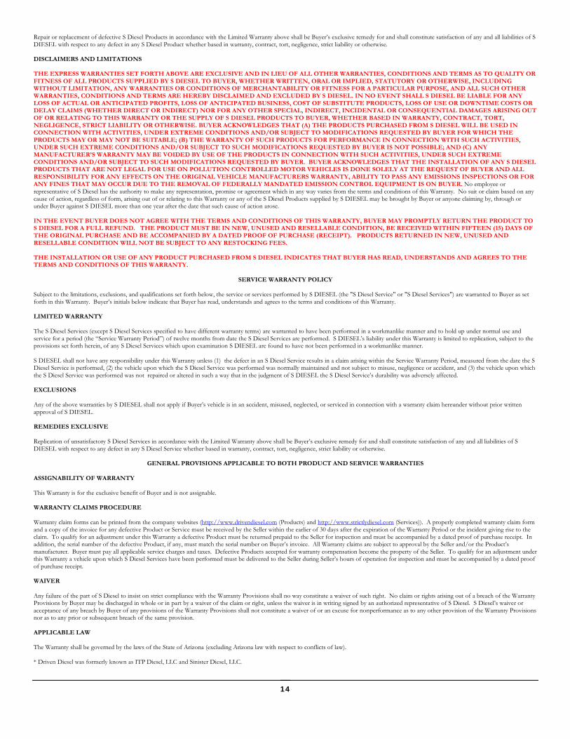
19. Locate the (2) 08MP-06MJ fittings and the Fuel Filter Head. 20. Using Fig. 11 as a guide, install the fittings and plugs securely into the filter head. These
fittings are pipe thread and require the use of Teflon tape or another thread sealant of your choice.
21. Locate the fuel filter mounting bracket, back plate, washers and nuts.
5
22. Using the (3) 1/4-20 Nylok Nuts and (3) 1/4” Flat Washers, attach the fuel filter head to the
fuel filter mounting bracket studs and tighten securely. 23. Insert (2) of the 3/8-16x4 bolts with 3/8” washers into the top holes of the fuel filter
mounting bracket. Using Fig. 12 as a guide, locate a spot on the inside of the frame to mount the bracket. There will be room in front of the fuel tank (leave as much room on both sides of the filter as possible). Hold the bracket in place with the bolts going over the top of the frame, start the backing plate and 2 more 3/8” washers over the bolts and loosely start (2) of the 3/8-16 Nylok nuts on the bolts.
24. Install the bottom 3/8-16x4 bolt, washers and nut in the same manner as the upper bolts. 25. Carefully tighten all (3) of the regulator mounting bracket nuts until the bracket is secure
and doesn’t move freely. DO NOT OVERTIGHTEN the nuts, they should NOT be tight enough to be bending the bracket! We have supplied Nylok nuts so they should not back off or loosen over time and should not require any excessive torque to secure the bracket.
26. Slide the fuel tank under the truck and install new 3/8” fuel line onto the pickup tube on top of the tank (larger tube of the 2). Push the hose over the rib and double clamp it as shown in figure 13 (it may be helpful to soak the end of the hose in HOT water for a few minutes, or to lube the metal pickup tube). Reconnect the sending unit wiring harness and factory return line as well. It would be a good idea to cover the end of the stock feed line (larger hose) with a plastic bag and zip tie.
27. Lift the fuel tank part way back into position and reconnect the front and rear vent hoses. Locate the fuel fill and vent hoses in such a way that they will slide over the frame as the tank is lifted the rest of the way into position.
28. Make sure that the new fuel line is routed carefully along the frame to avoid pinching or rubbing and raise the fuel tank into position.
29. Carefully route the 3/8” hose along the frame to the new filter. Leave a little slack and cut the hose to length. Slide one of the PC10 pinch clamps a few inches up the hose and then install one of the 06NC-06FJX onto the end of the hose (make sure the hose seats FULLY against the yellow stop disc). Position the PC10 pinch clamp over the hose barb, about ¼” from the end of the hose. Securely attach the hose to the inlet of the filter.
30. Install the second PC10 pinch clamp and 06NC-06FJX onto the remaining hose and securely connect it to the outlet side of the filter. Route the hose along the frame rail to the stock fuel pump. Disconnect the factory fuel line from the pump, you may want to cover the end of the factory line at this end as well. Cut the new 3/8” fuel line to length, slide it over the pump nipple (over the ridge like the tank) and double clamp. Continue to step 30.
30. Secure the new hose with zip ties in several places along the frame to prevent rubbing. 31. If you have some fuel, it is helpful (and recommended) to fill the fuel filter before installing it
onto the filter head. If not, the pump will be able to take care of it when you cycle the key but it will take longer to purge the air.
32. Install the small rubber gasket from the filter onto the filter head nipple, then install the filter in onto the filter head. It is a good idea to lightly lubricate the rubber seal on the filter.
33. Once you have finished, test the system by turning the ignition key to the “ON” position, but do not start the engine yet. While the fuel pump is running, check the lines for any signs of leakage. Resolve any leaks before continuing. Cycle the key from “off” to “on” several times, waiting about 20 seconds each time. This will allow the pump to purge any air in the system and completely fill the filter.
34. Once you have confirmed that the system is leak free, go ahead and start the engine.

6
Congratulations! You have completed the installation of the Driven Diesel Fuel Tank / Pre-Pump Kit!
For your convenience, We’ve included a cross-reference for replacement filters. Driven Diesel keeps the Baldwin filters in stock and would appreciate the opportunity to provide you with direct replacements. You can use the following list to get replacement filters elsewhere if desired. There are other filters that will fit this head as well, these are the filters that directly replace the Baldwin unit we’ve provided with the kit. Baldwin BF1212 Donaldson P55-8020 Fleetguard FS1212 Fram PS3712 Luberfiner LFF8020 WIX 3340 Fuel Filter Specs (BF1212): Flow Capability: 210gph @ 1psid / >300gph @ 3psid Filtration: 86% Efficient @ 4 micron / 99% Efficient @ 20 micron Water Removal: 93% @ 60gph / 87% @ 120gph (based on 2500ppm free water injection) (emulsified water removal will be approximately 3-5% less) Burst Pressure: 150psi Collapse Pressure: 100psid
7
Figure 1- Line release tool
Figure 2 - Removing the lock ring
8
Figure 3 - Measuring the old dimension
Figure 4 - Cutting the hose clamp
9
Figure 5 - Removing the mixing valve
Figure 6

10
Figure 7 – Removing Filter Screen
Figure 8

11
Figure 9
Figure 10 – Ready for installation
12
Figure 11 – Filter Head Mounted on Bracket – Arrows Indicate Flow Direction
Figure 12 – Filter Bracket Mounted Inside Frame Rail

13
Figure 13 – New Fuel Line Double Clamped on Pickup Tube (Excursion Shown)
S DIESEL, LLC (dba STRICTLY DIESEL AND/OR DRIVEN DIESEL*) WARRANTY AND LIABILITY POLICY
MOST OF THE PRODUCTS SOLD BY S DIESEL, LLC, ARE DESIGNED TO INCREASE VEHICLE
PERFORMANCE…USE AT YOUR OWN RISK!
Do not install or use any product(s) purchased from S DIESEL, LLC (“S DIESEL”) until you have carefully read the following Warranty and Liability Policy (the “Warranty”).
PRODUCT WARRANTY POLICY
Subject to the limitations, exclusions, and qualifications set forth below, the product or the products made and sold by S DIESEL (the "S Diesel Product" or "S Diesel Products") are warranted to Buyer as set forth in this Warranty. The installation of the S Diesel Products indicates that Buyer has read, understands and agrees to the terms and conditions of this Warranty. Any warranty on products that are made by another manufacturer which are resold by S DIESEL to Buyer is made to Buyer by the manufacturer of such products in accordance with and subject to all conditions and limitations of the manufacturer's warranty in effect on the date of the purchase by Buyer. S DIESEL makes no warranties to Buyer, express or implied, with respect to such products that are made by another manufacturer. LIMITED WARRANTY The S Diesel Products (except S Diesel Products specified to have different warranty terms) are warranted to be free from defects in material and workmanship, under normal use and service for a period (the “Product Warranty Period”) of ninety (90) days from date of delivery to Buyer, unless S DIESEL performs the work installing the S Diesel Products, in which case the Product Warranty Period shall be extended to equal the Service Warranty Period (as defined below under “SERVICE WARRANTY POLICY”). S DIESEL’s liability under this Warranty is limited to repair or replacement at its option, subject to the provisions set forth herein, of any S Diesel Products which upon examination S DIESEL are found to be defective. Buyer shall prepay cost of transportation of defective S Diesel Products to S DIESEL for inspection. S DIESEL shall not have any responsibility under this Warranty unless (1) the defect in an S Diesel Product results in a claim arising within the Product Warranty Period, measured from the date of delivery to Buyer, (2) the S Diesel Product, if installed by an installer other than S DIESEL, was properly installed, (3) the S Diesel Product was normally maintained and not subject to misuse, negligence or accident, and (4) the S Diesel Product, system components and/or accessories were not repaired or altered in such a way that in the judgment of S DIESEL the S Diesel Product’s performance or reliability was adversely affected. EXCLUSIONS Any of the above warranties by S DIESEL shall not apply if Buyer’s vehicle is in an accident, misused, neglected, altered from the S Diesel Product’s manufacturer original designs or specifications or serviced in connection with a warranty claim hereunder without prior written approval of S DIESEL. REMEDIES EXCLUSIVE
14
Repair or replacement of defective S Diesel Products in accordance with the Limited Warranty above shall be Buyer’s exclusive remedy for and shall constitute satisfaction of any and all liabilities of S DIESEL with respect to any defect in any S Diesel Product whether based in warranty, contract, tort, negligence, strict liability or otherwise. DISCLAIMERS AND LIMITATIONS THE EXPRESS WARRANTIES SET FORTH ABOVE ARE EXCLUSIVE AND IN LIEU OF ALL OTHER WARRANTIES, CONDITIONS AND TERMS AS TO QUALITY OR FITNESS OF ALL PRODUCTS SUPPLIED BY S DIESEL TO BUYER, WHETHER WRITTEN, ORAL OR IMPLIED, STATUTORY OR OTHERWISE, INCLUDING WITHOUT LIMITATION, ANY WARRANTIES OR CONDITIONS OF MERCHANTABILITY OR FITNESS FOR A PARTICULAR PURPOSE, AND ALL SUCH OTHER WARRANTIES, CONDITIONS AND TERMS ARE HEREBY DISCLAIMED AND EXCLUDED BY S DIESEL. IN NO EVENT SHALL S DIESEL BE LIABLE FOR ANY LOSS OF ACTUAL OR ANTICIPATED PROFITS, LOSS OF ANTICIPATED BUSINESS, COST OF SUBSTITUTE PRODUCTS, LOSS OF USE OR DOWNTIME COSTS OR DELAY CLAIMS (WHETHER DIRECT OR INDIRECT) NOR FOR ANY OTHER SPECIAL, INDIRECT, INCIDENTAL OR CONSEQUENTIAL DAMAGES ARISING OUT OF OR RELATING TO THIS WARRANTY OR THE SUPPLY OF S DIESEL PRODUCTS TO BUYER, WHETHER BASED IN WARRANTY, CONTRACT, TORT, NEGLIGENCE, STRICT LIABILITY OR OTHERWISE. BUYER ACKNOWLEDGES THAT (A) THE PRODUCTS PURCHASED FROM S DIESEL WILL BE USED IN CONNECTION WITH ACTIVITIES, UNDER EXTREME CONDITIONS AND/OR SUBJECT TO MODIFICATIONS REQUESTED BY BUYER FOR WHICH THE PRODUCTS MAY OR MAY NOT BE SUITABLE; (B) THE WARRANTY OF SUCH PRODUCTS FOR PERFORMANCE IN CONNECTION WITH SUCH ACTIVITIES, UNDER SUCH EXTREME CONDITIONS AND/OR SUBJECT TO SUCH MODIFICATIONS REQUESTED BY BUYER IS NOT POSSIBLE; AND (C) ANY MANUFACTURER’S WARRANTY MAY BE VOIDED BY USE OF THE PRODUCTS IN CONNECTION WITH SUCH ACTIVITIES, UNDER SUCH EXTREME CONDITIONS AND/OR SUBJECT TO SUCH MODIFICATIONS REQUESTED BY BUYER. BUYER ACKNOWLEDGES THAT THE INSTALLATION OF ANY S DIESEL PRODUCTS THAT ARE NOT LEGAL FOR USE ON POLLUTION CONTROLLED MOTOR VEHICLES IS DONE SOLELY AT THE REQUEST OF BUYER AND ALL RESPONSIBILITY FOR ANY EFFECTS ON THE ORIGINAL VEHICLE MANUFACTURERS WARRANTY, ABILITY TO PASS ANY EMISSIONS INSPECTIONS OR FOR ANY FINES THAT MAY OCCUR DUE TO THE REMOVAL OF FEDERALLY MANDATED EMISSION CONTROL EQUIPMENT IS ON BUYER. No employee or representative of S Diesel has the authority to make any representation, promise or agreement which in any way varies from the terms and conditions of this Warranty. No suit or claim based on any cause of action, regardless of form, arising out of or relating to this Warranty or any of the S Diesel Products supplied by S DIESEL may be brought by Buyer or anyone claiming by, through or under Buyer against S DIESEL more than one year after the date that such cause of action arose. IN THE EVENT BUYER DOES NOT AGREE WITH THE TERMS AND CONDITIONS OF THIS WARRANTY, BUYER MAY PROMPTLY RETURN THE PRODUCT TO S DIESEL FOR A FULL REFUND. THE PRODUCT MUST BE IN NEW, UNUSED AND RESELLABLE CONDITION, BE RECEIVED WITHIN FIFTEEN (15) DAYS OF THE ORIGINAL PURCHASE AND BE ACCOMPANIED BY A DATED PROOF OF PURCHASE (RECEIPT). PRODUCTS RETURNED IN NEW, UNUSED AND RESELLABLE CONDITION WILL NOT BE SUBJECT TO ANY RESTOCKING FEES. THE INSTALLATION OR USE OF ANY PRODUCT PURCHASED FROM S DIESEL INDICATES THAT BUYER HAS READ, UNDERSTANDS AND AGREES TO THE TERMS AND CONDITIONS OF THIS WARRANTY.
SERVICE WARRANTY POLICY
Subject to the limitations, exclusions, and qualifications set forth below, the service or services performed by S DIESEL (the "S Diesel Service" or "S Diesel Services") are warranted to Buyer as set forth in this Warranty. Buyer’s initials below indicate that Buyer has read, understands and agrees to the terms and conditions of this Warranty. LIMITED WARRANTY The S Diesel Services (except S Diesel Services specified to have different warranty terms) are warranted to have been performed in a workmanlike manner and to hold up under normal use and service for a period (the “Service Warranty Period”) of twelve months from date the S Diesel Services are performed. S DIESEL’s liability under this Warranty is limited to replication, subject to the provisions set forth herein, of any S Diesel Services which upon examination S DIESEL are found to have not been performed in a workmanlike manner. S DIESEL shall not have any responsibility under this Warranty unless (1) the defect in an S Diesel Service results in a claim arising within the Service Warranty Period, measured from the date the S Diesel Service is performed, (2) the vehicle upon which the S Diesel Service was performed was normally maintained and not subject to misuse, negligence or accident, and (3) the vehicle upon which the S Diesel Service was performed was not repaired or altered in such a way that in the judgment of S DIESEL the S Diesel Service’s durability was adversely affected. EXCLUSIONS Any of the above warranties by S DIESEL shall not apply if Buyer’s vehicle is in an accident, misused, neglected, or serviced in connection with a warranty claim hereunder without prior written approval of S DIESEL. REMEDIES EXCLUSIVE Replication of unsatisfactory S Diesel Services in accordance with the Limited Warranty above shall be Buyer’s exclusive remedy for and shall constitute satisfaction of any and all liabilities of S DIESEL with respect to any defect in any S Diesel Service whether based in warranty, contract, tort, negligence, strict liability or otherwise.
GENERAL PROVISIONS APPLICABLE TO BOTH PRODUCT AND SERVICE WARRANTIES
ASSIGNABILITY OF WARRANTY This Warranty is for the exclusive benefit of Buyer and is not assignable. WARRANTY CLAIMS PROCEDURE Warranty claim forms can be printed from the company websites (http://www.drivendiesel.com (Products) and http://www.strictlydiesel.com (Services)). A properly completed warranty claim form and a copy of the invoice for any defective Product or Service must be received by the Seller within the earlier of 30 days after the expiration of the Warranty Period or the incident giving rise to the claim. To qualify for an adjustment under this Warranty a defective Product must be returned prepaid to the Seller for inspection and must be accompanied by a dated proof of purchase receipt. In addition, the serial number of the defective Product, if any, must match the serial number on Buyer’s invoice. All Warranty claims are subject to approval by the Seller and/or the Product’s manufacturer. Buyer must pay all applicable service charges and taxes. Defective Products accepted for warranty compensation become the property of the Seller. To qualify for an adjustment under this Warranty a vehicle upon which S Diesel Services have been performed must be delivered to the Seller during Seller’s hours of operation for inspection and must be accompanied by a dated proof of purchase receipt. WAIVER Any failure of the part of S Diesel to insist on strict compliance with the Warranty Provisions shall no way constitute a waiver of such right. No claim or rights arising out of a breach of the Warranty Provisions by Buyer may be discharged in whole or in part by a waiver of the claim or right, unless the waiver is in writing signed by an authorized representative of S Diesel. S Diesel’s waiver or acceptance of any breach by Buyer of any provisions of the Warranty Provisions shall not constitute a waiver of or an excuse for nonperformance as to any other provision of the Warranty Provisions nor as to any prior or subsequent breach of the same provision. APPLICABLE LAW The Warranty shall be governed by the laws of the State of Arizona (excluding Arizona law with respect to conflicts of law). * Driven Diesel was formerly known as ITP Diesel, LLC and Sinister Diesel, LLC.