fuji bw series (100/160/250af) mccb - cleswitch.com.tw
TRANSCRIPT

EEH120
FUJI BW Series (100/160/250AF)
MCCBMolded Case Circuit Breakers

Fuji Electric FA components & Systems Co.,Ltd. was formed in 2003under the parent company Fuji Electric Holdings Co.,Ltd . which wasestablished in 1923.MCCB production started in 1968, and the hard earned expertise gainedover the years has established global reputation for high quality.MCCBs are used in many different types of electrical distribution andcontrol systems.The most important requirement is to provide depend-able, safe protection of load devices in the event of a short-circuit.Making use of related technologies, Fuji Electric FA components &Systems Co.,Ltd. has developed a global frame size lineup of MCCBs.This time we provide a three-fold concept for compact, cassette-type,BW series MCCBs, resulting in a global series.
Compact
We’ve expanded our MCCB lineup withthe addition of models with
global frame sizes of 160AF and 250AF.
We’ve applied high-performance technology to achieve 100AF to 250AF models witha uniform depth of 60 mm.Compact design has been realized for the MCCB family series from 30AF to 800AF.We’ve achieved a Ics of 50% Icu.
2

Cassette
GlobalIntroducing new frame sizes: 160AF and 250AFFully compliant with IEC standards while providing the required safety.
All accessories can be assembled by the user.Quickly adaptable to the many onsite changesin specifications.
3

Compact
4
We’ve reduced external dimensions and increasedmodularization to the limits. Customers can now reduce costsin panel design and manufacturing.

Reducing external dimensions and unifying the depth to 60 mm
lead to smaller panels and easier manufacturing.
For the 30AF to 250AF models, unifying the depth to 60 mm has
enabled reduced costs and standardized panel design and
manufacturing.
Using uniform external dimensions provides flexibility in
responding to changes in specifications.
The 30AF to 100AF models can be mounted on IEC 35mm rail for
easy panel mounting.
Enhanced Breaking Technology“BW Series” circuit breaker emploies an unique and ideal
breaking mechanism that give you enhanced breaking capability
from the beginning to completion of interruption.
Achieve high speed contact opening according to increasing
electromagnetic force to opening direction by joint using of flat
stationary contact and magnetic yoke.
Accelerate movable contact speed by arcing gas generated from
special resin located closely to movable contact.
Drastically reducing clearing I2t according to increasing arc
driving force to arc chamber by magnetic yoke to rise arc voltage
rapidly.
5
Magnetic yoke
Arc chamber
Resin nearby contacts
Flat stationary contact
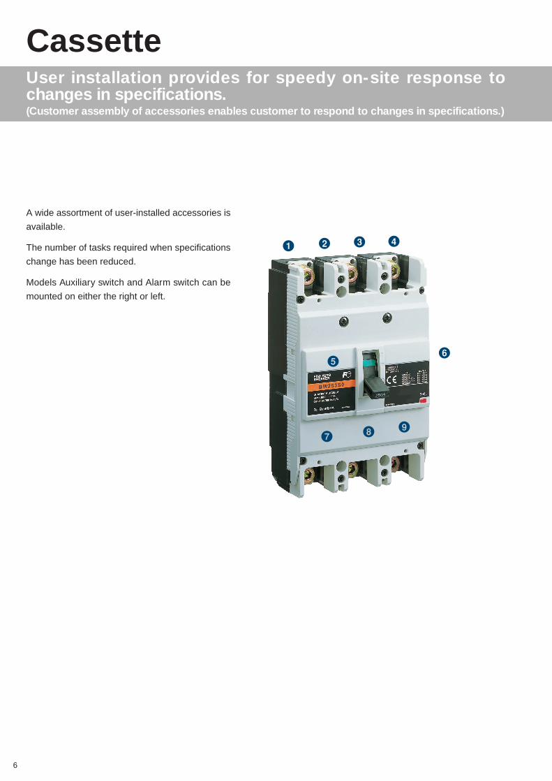
User installation provides for speedy on-site response tochanges in specifications.(Customer assembly of accessories enables customer to respond to changes in specifications.)
Cassette
A wide assortment of user-installed accessories is
available.
The number of tasks required when specifications
change has been reduced.
Models Auxiliary switch and Alarm switch can be
mounted on either the right or left.
6
1 2 3
6
4
87
5
9

Accessory
7
3Insulation barrier lnterphase
6Undervltage release
4Flat terminal1Terminal cover Short 2Terminal cover Long
8Operating handle V-type
9Handle locking device
7Operating handle N-type
5Auxiliary switch,Alarm switch,Shunt trip

Compliance with the IEC standards in pursuit of global standards.
We’ve expanded our lineup by adding the 160AF and 250AF
global frames.
Conformity with international standards such as IEC 60947-2 for
all models. Standards conformity
information is given on the nameplate.
Gray, has been adopted as the color for the front surface.
Compliance with the IEC standards in pursuitof global standards.
Global
8
Application by interrupting capacity
BW102S0BW103S0
BW162S0BW163S0
BW162J0BW163J0
BW252S0BW253S0
BW252J0BW253J0
BW103E0BW162E0BW163E0
BW252E0BW253E0
(Amp)
(kA at 415V AC)
IEC
40
(36)
30
(25)
20(18)
(15)
10
0 15A 100A 150A 160A 200A 250A

9
I N D E X
Line-up
Quick reference guide
Installation
Characteristic curves
Dimensions
Accessories
10
12
28
30
32
18
L
Q
I
C
D
A

• [NEW] FUJI MCCBs Family of Product Models ( 2/3- poles for Line Protection )
Line-up
10
Series
Frame size
Poles
Type
Ordering Code
Note (with)
Rated Current (A)
Rated interrupting
capacity (kA)
IEC60947-2 (Icu/Ics)
See pages
415V AC
380V AC
230V AC
160
2
BW162E0
BW162E0
-
100, 125, 150,
160
18 / 9
18 / 9
25 / 13
E
100
3
BW103E0
BW103E0
-
15, 20, 25, 30,
40, 50, 60, 75,
80,100
15 / 8
18 / 9
25 / 13
12
250
2
BW252E0
BW252E0
-
175, 200, 225,
250
18 / 9
18 / 9
25 / 13
13
3
BW163E0
BW163E0
-
3
BW253E0
BW253E0
-
S
100
2
BW102S0
BW102S0
-
15, 20, 25, 30,
40, 50, 60, 75,
80, 100
30 / 8
30 / 15
50 / 25
14
160
2
BW162J0
BW162J0
-
100, 125, 150,
160
25 / 13
25 / 13
50 / 25
15
3
BW103S0
BW103S0
-
30 / 8
30 / 15
100 / 50
2
BW162S0
BW162S0
-
100, 125, 150,
160
36 / 18
36 / 18
85 / 43
3
BW163S0
BW163S0
-
3
BW163J0
BW163J0
-
250
2
BW252J0
BW252J0
-
175, 200, 225,
250
25 / 13
25 / 13
50 / 25
16
2
BW252S0
BW252S0
-
175, 200, 225,
250
36 / 18
36 / 18
85 / 43
3
BW253S0
BW253S0
-
3
BW253J0
BW253J0
-
Series
Frame size
Poles
Type
Ordering Code
Note (with)
Rated Current (A)
Rated interrupting
capacity (kA)
IEC60947-2 (Icu/Ics)
See pages
415V AC
380V AC
230V AC
3
SA33C
BB3ASC
-CE
S
30
2
SA32C
BB2ASC
-CE
3, 5, 10, 15, 20, 30
2.5 / 2
2.5 / 2
5 / 3
*1
3
SA53C
BB3BSC
-CE
50
2
SA52C
BB2BSC
-CE
5, 10, 15, 20, 30, 40, 50
7.5 / 4
7.5 / 4
10 / 5
2
SA52RC
BB2BRC
-CE
10, 15, 20, 30, 40, 50
10 / 5
10 / 5
25 / 13
3
SA53RC
BB3BRC
-CE
3
SA63C
BB3CSC
-CE
60
2
SA62C
BB2CSC
-CE
60
7.5 / 4
7.5 / 4
10 / 5
3
SA63RC
BB3CRC
-CE
2
SA62RC
BB2CRC
-CE
60
10 / 5
10 / 5
25 / 13
Series
Frame size
Poles
Type
Ordering Code
Note (with)
Rated Current (A)
Rated interrupting
capacity (kA)
IEC60947-2 (Icu/Ics)
See pages
415V AC
380V AC
230V AC
3
EA203C
BB3GEC
-CE
E
225
2
EA202C
BB2GEC
-CE
125, 150,175, 200, 225
18 / 5
18 / 5
35 / 18
*1
3
EA403C
BB3KEC
-CE
400
2
EA402C
BB2KEC
-CE
250, 300, 350, 400
25 / 13
25 / 13
35 / 18
600
3
EA603C
BB3LEC
-CE
500, 600
35 / 18
35 / 18
50 / 25
800
3
EA803
BB3MEC
-CE
700, 800
35 / 18
35 / 18
50 / 25
Series
Frame size
Poles
Type
Ordering Code
Note (with)
Rated Current (A)
Rated interrupting
capacity (kA)
IEC60947-2 (Icu/Ics)
See pages
415V AC
380V AC
230V AC
3
SA103C
BB3ESD
-CE
S
100
2
SA102C
BB2ESD
-CE
15, 20, 30, 40, 50, 60, 75, 100
30 / 8
30 / 8
50 / 25
*1
3
SA103RC
BB3ERD
-CE
2
SA102RC
BB2ERD
-CE
15, 20, 30, 40, 50,60, 75, 100
50 / 13
50 / 13
100 / 50
3
SA203C
BB3GSD
-CE
225
2
SA202C
BB2GSD
-CE
125, 150, 175, 200, 225
30 / 8
30 / 8
50 / 25
2
SA202RC
BB2GRD
-CE
125, 150, 175, 200, 225
50 / 13
50 / 13
100 / 50
3
SA203RC
BB3GRD
-CE
Series
Frame size
Poles
Type
Ordering Code
Note (with)
Rated Current (A)
Rated interrupting
capacity (kA)
IEC60947-2 (Icu/Ics)
See pages
415V AC
380V AC
230V AC
3
EA33AC
BB3AEAC
-CE
E
3 0
2
EA32AC
BB2AEAC
-CE
3, 5, 10, 15, 20, 30
1.5 / 1
1.5 / 1
2.5 / 2
*1
50
2
EA52C
BB2BEC
-CE
5, 10, 15, 20, 30, 40, 50
2.5 / 2
2.5 / 2
5 / 3
3
EA53C
BB3BEC
-CE
3
EA63C
BB3CEC
-CE
6 0
2
EA62C
BB2CEC
-CE
60
2.5 / 2
2.5 / 2
5 / 3
3
EA103C
BB3EEC
-CE
1 0 0
2
EA102C
BB2EEC
-CE
50, 60, 75, 100
10 / 5
10 / 5
25 / 13
• FUJI MCCBs Family of Product Models ( 2/3- poles for Line Protection )

SOON TO BE RELEASED
SOON TO BE RELEASED
11MCCBLine-up
• FUJI MCCBs Family of Product Models ( 3-poles for Line Protection )
• FUJI MCCBs Family of Product Models ( 4-poles for Line Protection )
L
Series
Frame size
Poles
Type
Ordering Code
Note (with)
Rated Current (A)
Rated interrupting
capacity (kA)
IEC60947-2 (Icu/Ics)
See pages
415V AC
380V AC
230V AC
3
SA403C
BB3KSC
-CE
S
400
2
SA402C
BB2KSC
-CE
250, 300, 350, 400
35 / 18
35 / 18
50 / 25
*1
3
SA403RC
BB3KRC
-CE
2
SA402RC
BB2KRC
-CE
250, 300, 350, 400
50 / 25
50 / 25
85 / 43
800
3
SA803RC
BB3MRC
-CE
700, 800
50 / 25
50 / 25
85 / 43
600
3
SA603RC
BB3LRC
-CE
500, 600
50 / 25
50 / 25
85 / 43
1000
3
SA1003E
BE3NSA
-CE
500-1000
65 / 49
85 / 64
100 / 75
1250
3
SA1253E
BE3SSB
-CE
630-1250
65 / 49
85 / 64
100 / 75
1600
3
SA1603E
BE3TSA
-CE
800-1600
85 / 64
100 / 75
125 / 94
Series
Frame size
Poles
Type
Note (with)
Rated Current (A)
Rated interrupting
capacity (kA)
IEC60947-2 (Icu/Ics)
440V AC
400V AC
230V AC
S
100
4
SA104BA
-
15, 20, 30, 40, 50
60, 75, 100
25 / 13
30 / 15
50 / 25
225
4
SA204BA
-
125, 150, 175, 200
225
25 / 13
35 / 18
50 / 25
400
4
SA404BA
-
250, 300, 350, 400
35 / 18
35 / 18
50 / 25
600
4
SA604BA
-
500, 600
35 / 18
45 / 23
50 / 25
800
4
SA804BA
-
700, 800
35 / 18
45 / 23
50 / 25
Series
Frame size
Poles
Type
Note (with)
Rated Current (A)
Rated interrupting
capacity (kA)
IEC60947-2 (Icu/Ics)
440V AC
400V AC
230V AC
H
100
3
H103CA
-
15, 20, 30, 40, 50
60, 75, 100
70 / 70
70 / 70
100 / 100
225
3
H203CA
-
125, 150, 175, 200
225
70 / 70
70 / 70
100 / 100
400
3
H403C
-
250, 300, 350, 400
70 / 35
70 / 35
125 / 63
600
3
H603C
-
500, 600
70 / 35
70 / 35
125 / 63
800
3
H803C
-
700, 800
70 / 35
70 / 35
125 / 63
Notes: For FUJI ELCB product family, refer to FUJI D&C CATALOG (Individual Catalog No.07). *1 For details, refer to FUJI D&C CATALOG (Individual Catalog No.06).
4
SA104RA
-
50 / 25
50 / 25
85 / 43
4
SA204RA
-
50 / 25
50 / 25
85 / 43
4
SA404RA
-
50 / 25
50 / 25
85 / 43
4
SA604RA
-
50 / 25
65 / 33
85 / 43
4
SA804RA
-
50 / 25
65 / 33
85 / 43

Quick reference guide (Line Protection)
12
■ E series/2, 3-pole IEC and CE marking conformed typesFramePoleTypeRated current (A)Rated insulation voltage (V AC)[IEC 60947-2, JIS C8201-2] (V DC)Rated interrupting capacity (kA) 600V ACIEC 60947-2 550V ACJIS C 8201-2 440V AC(Icu/Ics) *1 415V AC
400V AC380V AC240V AC230V AC250V DC
Dimensions (mm) ab
Page 32, 33 cd
Mass (kg) Front mounting typeTripping deviceFront mounting, front connectionInternal accessories See page 18
Auxiliary switch Alarm switch Auxiliary switch + Alarm switch Shunt trip Under voltage releaseExternal accessories See page 22
Operating handle N type Operating handle V type Terminal cover Short Terminal cover Long Insulation barrier Interphase Flat terminal Block terminal Handle locking device IEC 35mm rail mounting Notes: *1 Icu: Rated ultimate short-circuit breaking capacity ● Available – Not available
Ics: Rated service short-circuit breaking capacity
a dc
b
100A3BW103E015, 20, 25, 30, 40, 50, 60, 75, 80, 100690250–5/310/515/815/818/925/1325/135/37513060810.78Thermal-magnetic●
●
●
●
●
●
●
●
–●
●
–●
●
●
160A2BW162E0100, 125, 150, 160690250–5/315/818/918/918/925/1325/135/310516560861.36
●
●
●
●
●
●
●
●
●
●
●
●
●
●
–
3BW163E0100, 125, 150, 160690250–5/315/818/918/918/925/1325/135/310516560861.56
●
●
●
●
●
●
●
●
●
●
●
●
●
●
–

13MCCBQuick reference guide (Line Protection)
Q
■ E series/2, 3-pole IEC and CE marking conformed typesFramePoleTypeRated current (A)Rated insulation voltage (V AC)[IEC 60947-2, JIS C8201-2] (V DC)Rated interrupting capacity (kA) 600V ACIEC 60947-2 550V ACJIS C 8201-2 440V AC(Icu/Ics) *1 415V AC
400V AC380V AC240V AC230V AC250V DC
Dimensions (mm) ab
Page 32, 33 cd
Mass (kg) Front mounting typeTripping deviceFront mounting, front connectionInternal accessories See page 18
Auxiliary switch Alarm switch Auxiliary switch + Alarm switch Shunt trip Under voltage releaseExternal accessories See page 22
Operating handle N type Operating handle V type Terminal cover Short Terminal cover Long Insulation barrier Interphase Flat terminal Block terminal Handle locking device IEC 35mm rail mounting Notes: *1 Icu: Rated ultimate short-circuit breaking capacity ● Available – Not available
Ics: Rated service short-circuit breaking capacity
a dc
b
3BW253E0175, 200, 225, 250690250–5/315/818/918/918/925/1325/135/310516560861.56
●
●
●
●
●
●
●
●
●
●
●
●
●
●
–
250A2BW252E0175, 200, 225, 250690250–5/315/818/918/918/925/1325/135/310516560861.36Thermal-magnetic●
●
●
●
●
●
●
●
●
●
●
●
●
●
–
Quick reference guide (Line Protection)
14
FramePoleTypeRated current (A)Rated insulation voltage (V AC)[IEC 60947-2, JIS C8201-2] (V DC)Rated interrupting capacity (kA) 600V ACIEC 60947-2 550V ACJIS C 8201-2 440V AC(Icu/Ics) *1 415V AC
400V AC380V AC240V AC230V AC250V DC
Dimensions (mm) ab
Page 32, 33 cd
Mass (kg) Front mounting typeTripping deviceFront mounting, front connectionInternal accessories See page 18
Auxiliary switch Alarm switch Auxiliary switch + Alarm switch Shunt trip Under voltage releaseExternal accessories See page 22
Operating handle N type Operating handle V type Terminal cover Short Terminal cover Long Insulation barrier Interphase Flat terminal Block terminal Handle locking device IEC 35mm rail mounting Notes: *1 Icu: Rated ultimate short-circuit breaking capacity ● Available – Not available
Ics: Rated service short-circuit breaking capacity
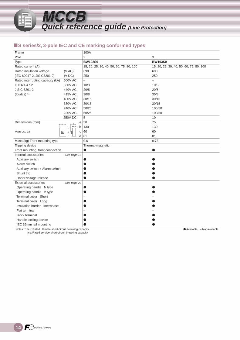
100A2BW102S015, 20, 25, 30, 40, 50, 60, 75, 80, 100690250–10/320/530/830/1530/1550/2550/2555013060810.6Thermal-magnetic●
●
●
●
●
●
●
●
–●
●
–●
●
●
3BW103S015, 20, 25, 30, 40, 50, 60, 75, 80, 100690250–10/320/530/830/1530/15100/50100/50107513060810.78
●
●
●
●
●
●
●
●
–●
●
–●
●
●
■ S series/2, 3-pole IEC and CE marking conformed types
a dc
b

15MCCBQuick reference guide (Line Protection)
Q
■ S series/2, 3-pole IEC and CE marking conformed typesFramePoleTypeRated current (A)Rated insulation voltage (V AC)[IEC 60947-2, JIS C8201-2] (V DC)Rated interrupting capacity (kA) 600V ACIEC 60947-2 550V ACJIS C 8201-2 440V AC(Icu/Ics) *1 415V AC
400V AC380V AC240V AC230V AC250V DC
Dimensions (mm) ab
Page 32, 33 cd
Mass (kg) Front mounting typeTripping deviceFront mounting, front connectionInternal accessories See page 18
Auxiliary switch Alarm switch Auxiliary switch + Alarm switch Shunt trip Under voltage releaseExternal accessories See page 22
Operating handle N type Operating handle V type Terminal cover Short Terminal cover Long Insulation barrier Interphase Flat terminal Block terminal Handle locking device IEC 35mm rail mounting Notes: *1 Icu: Rated ultimate short-circuit breaking capacity ● Available – Not available
Ics: Rated service short-circuit breaking capacity
2BW162S0100, 125, 150, 160690250–10/525/1336/1836/1836/1885/4385/4330/1510516560861.36
●
●
●
●
●
●
●
●
●
●
●
●
●
●
–
3BW163S0100, 125, 150, 160690250–10/525/1336/1836/1836/1885/4385/4330/1510516560861.56
●
●
●
●
●
●
●
●
●
●
●
●
●
●
–
160A2BW162J0100, 125, 150, 160690250–8/420/1025/1325/1325/1350/2550/2520/1010516560861.36Thermal-magnetic●
●
●
●
●
●
●
●
●
●
●
●
●
●
–
3BW163J0100, 125, 150, 160690250–8/420/1025/1325/1325/1350/2550/2520/1010516560861.56
●
●
●
●
●
●
●
●
●
●
●
●
●
●
–
a dc
b

Quick reference guide (Line Protection)
16
■ S series/2, 3-pole IEC and CE marking conformed typesFramePoleTypeRated current (A)Rated insulation voltage (V AC)[IEC 60947-2, JIS C8201-2] (V DC)Rated interrupting capacity (kA) 600V ACIEC 60947-2 550V ACJIS C 8201-2 440V AC(Icu/Ics) *1 415V AC
400V AC380V AC240V AC230V AC250V DC
Dimensions (mm) ab
Page 32, 33 cd
Mass (kg) Front mounting typeTripping deviceFront mounting, front connectionInternal accessories See page 18
Auxiliary switch Alarm switch Auxiliary switch + Alarm switch Shunt trip Under voltage releaseExternal accessories See page 22
Operating handle N type Operating handle V type Terminal cover Short Terminal cover Long Insulation barrier Interphase Flat terminal Block terminal Handle locking device IEC 35mm rail mounting Notes: *1 Icu: Rated ultimate short-circuit breaking capacity ● Available – Not available
Ics: Rated service short-circuit breaking capacity
2BW252S0175, 200, 225, 250690250–10/525/1336/1836/1836/1885/4385/4330/1510516560861.36
●
●
●
●
●
●
●
●
●
●
●
●
●
●
–
3BW253S0175, 200, 225, 250690250–10/525/1336/1836/1836/1885/4385/4330/1510516560861.56
●
●
●
●
●
●
●
●
●
●
●
●
●
●
–
250A2BW252J0175, 200, 225, 250690250–8/420/1025/1325/1325/1350/1550/1520/1010516560861.36Thermal-magnetic●
●
●
●
●
●
●
●
●
●
●
●
●
●
–
3BW253J0175, 200, 225, 250690250–8/420/1025/1325/1325/1350/1550/1520/1010516560861.56
●
●
●
●
●
●
●
●
●
●
●
●
●
●
–
a dc
b

17MCCBQuick reference guide (Line Protection)
Q
BW 25 3 E0 / 250
SeriesE Series : BW E0
S Series : BW J0, BW S0
Frame size10: 100A Frame16: 160A Frame25: 250A Frame
Number of poles2: 2-pole3: 3-pole
Rated current15: 15A 100: 100A20: 20A 125: 125A25: 25A 150: 150A30: 30A 160: 160A40: 40A 175: 175A50: 50A 200: 200A60: 60A 225: 225A75: 75A 250: 250A80: 80A
■ Type number of MCCB accessoriesSee page 18 and later for the Type number of eachaccessory.
• ExampleSee page 24 for the selection of insulation barriersinterphase.3-pole, 250A Frame..................................... BZ-B40B
• ExampleS series3-pole, 250A Frame ................................... BW253S0Rated current 250A ............................................. 250
Complete type number BW253S0/250
■ Type number of MCCB body
18
■ Internal Accessories
MCCB Type
E series
BW103E0
BW162E0, BW163E0BW252E0, BW253E0
S series
BW102S0, BW103S0
BW162J0, BW163J0
BW162S0, BW163S0
BW252J0, BW253J0
BW252S0, BW253S0
Type number
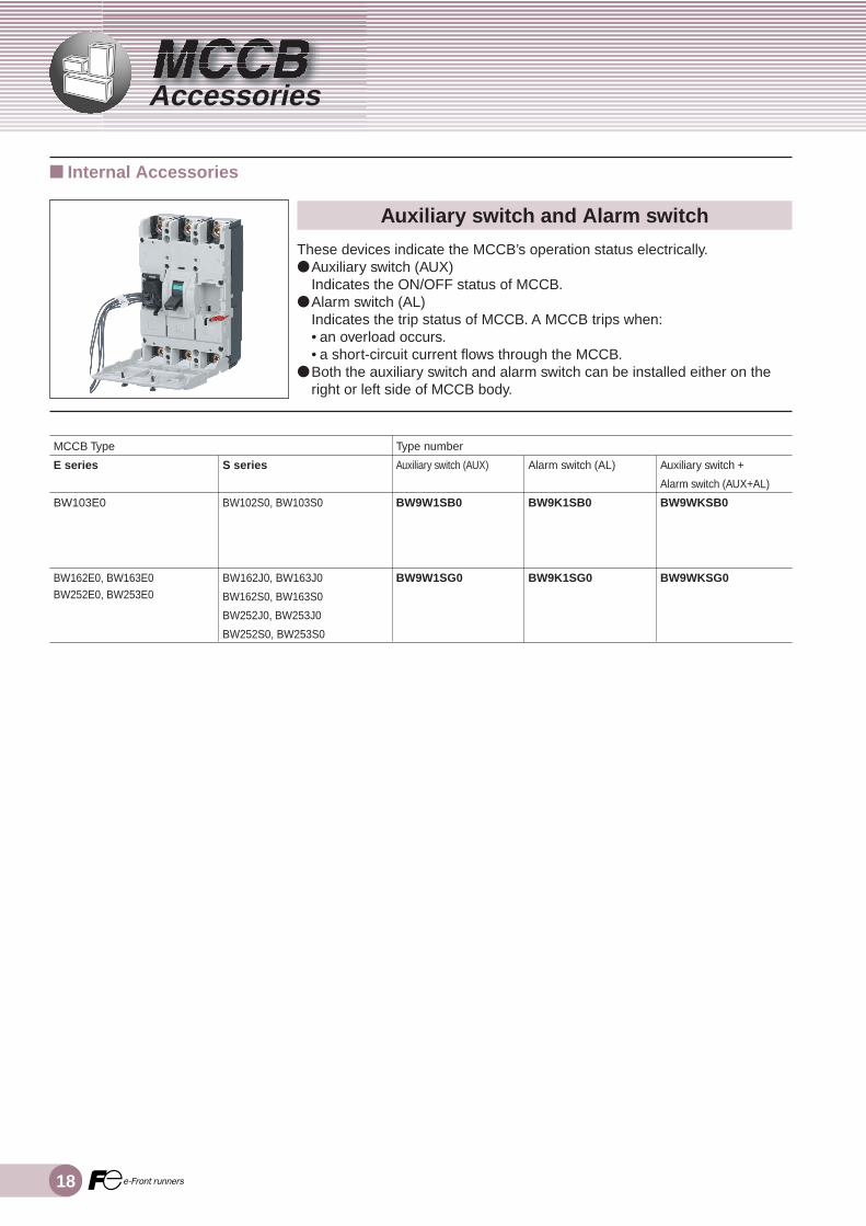
Auxiliary switch (AUX)
BW9W1SB0
BW9W1SG0
Auxiliary switch and Alarm switch
These devices indicate the MCCB’s operation status electrically.● Auxiliary switch (AUX)
Indicates the ON/OFF status of MCCB.● Alarm switch (AL)
Indicates the trip status of MCCB. A MCCB trips when:• an overload occurs.• a short-circuit current flows through the MCCB.
● Both the auxiliary switch and alarm switch can be installed either on theright or left side of MCCB body.
Alarm switch (AL)
BW9K1SB0
BW9K1SG0
Auxiliary switch +
Alarm switch (AUX+AL)
BW9WKSB0
BW9WKSG0
Accessories

19MCCBAccessories
A● Operation of auxiliary switches(AUX) and alarm switches(AL)Accessory
Auxiliary switch (AUX)
Alarm switch (AL)
Handle positionON 11
91
14
12
OFF 11
94
92
Trip 14
12
91 94
92
Type number
BW9W1SB0
BW9K1SB0
BW9WKSB0
BW9W1SG0
BW9K1SG0
BW9WKSG0
Make/Break current (A)
AC12
5
5
5
3
5
5
5
3
AC15
5
5
3
2
5
5
3
2
Make/Break current (A)
DC12
4
2.5
0.4
0.2
4
2.5
0.4
0.2
DC14
3
1
0.4
0.2
3
1
0.4
0.2
DC
Voltage (V)
24
48
125
250
24
48
125
250
Minimum
load current
5V DC 160mA
30V DC 30mA
• All auxiliary switches (AUX) and alarm switches (AL) are electricalpre-wired with wires of 1 mm2, 500 mm long.
• The auxiliary switch, alarm switch and auxiliary plus alarm switch havealmost the same appearance.
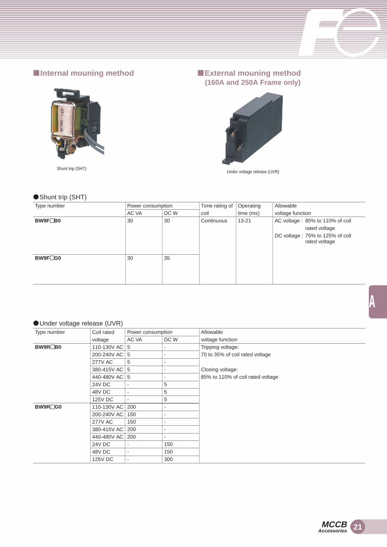
■ Internal mouning method
AC
Voltage (V)
24
48
125
250
24
48
125
250
● Rating of auxiliary switches (AUX) and alarm switches (AL)
Auxiliary switches + Alarm switches(AUX+AL)

20
MCCB typeE seriesBW103E0
BW162E0, BW163E0BW252E0, BW253E0
Note: Shunt trip (SHT) is capable of internal mounting only.Under voltage release (UVR) for 100AF is capable of internal mounting only.Under voltage release (UVR) for 160AF and 250AF is capable of external mounting only.
S seriesBW102S0, BW103S0
BW162J0, BW163J0BW162S0, BW163S0BW252J0, BW253J0BW252S0, BW253S0
Shunt trip (SHT) and Under voltage release (UVR)
• Shunt trip (SHT)A device that issues an electrical signal to trip the MCCB
• Under voltage release (UVR)A device that is used to trip the MCCB when the main circuit voltage dropslower than the specified value.
• Both the shunt trip and under voltage release can be installed on the rightside of MCCB body.
Operating voltage
100-130V AC200-240V AC277V AC380-415V AC440-480V AC24V DC48V DC125V DC100-130V AC200-240V AC277V AC380-415V AC440-480V AC24V DC48V DC125V DC
MCCB TypeE seriesBW103E0
BW162E0, BW163E0BW252E0, BW253E0
S seriesBW102S0, BW103S0
BW162J0, BW163J0BW162S0, BW163S0BW252J0, BW253J0BW252S0, BW253S0
Operating voltage
100-130V AC200-277V AC380-480V AC24V DC48V DC100-120V AC120-130V AC200-240V AC277V AC380-440V AC440-480V AC24V DC48V DC
● Under voltage release (UVR)
● Shunt trip (SHT)
■ Internal Accessories
Type number
BW9RAB0BW9RKB0BW9RBB0BW9RPB0BW9RHB0BW9RRB0BW9RSB0BW9RLB0BW9RAG0BW9RKG0BW9RBG0BW9RPG0BW9RHG0BW9RRG0BW9RSG0BW9RLG0
Type number
BW9FAB0BW9FKB0BW9FPB0BW9FRB0BW9FSB0BW9FAG0BW9F1G0BW9FKG0BW9FBG0BW9FPG0BW9FHG0BW9FRG0BW9FSG0
Accessories
CodeAKPRSA1KBPHRS
CodeAKBPHRSLAKBPHRSL
21MCCBAccessories
A
Coil ratedvoltage110-130V AC200-240V AC277V AC380-415V AC440-480V AC24V DC48V DC125V DC110-130V AC200-240V AC277V AC380-415V AC440-480V AC24V DC48V DC125V DC
Type number
BW9F B0
BW9F G0
Type number
BW9R B0
BW9R G0
Power consumptionAC VA55555---200150150200200---
DC W-----555-----150150300
Allowablevoltage functionTripping voltage:70 to 35% of coil rated voltage
Closing voltage:85% to 110% of coil rated voltage
Power consumptionAC VA30
30
DC W30
35
Time rating ofcoilContinuous
Operatingtime (ms)13-21
Allowablevoltage functionAC voltage : 85% to 110% of coil
rated voltageDC voltage : 75% to 125% of coil
rated voltage
Shunt trip (SHT)
● Under voltage release (UVR)
● Shunt trip (SHT)
■ Internal mouning method ■ External mouning method(160A and 250A Frame only)
Under voltage release (UVR)
22
■ External accessories
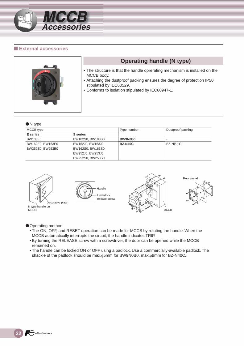
● Operating method• The ON, OFF, and RESET operation can be made for MCCB by rotating the handle. When the
MCCB automatically interrupts the circuit, the handle indicates TRIP.• By turning the RELEASE screw with a screwdriver, the door can be opened while the MCCB
remained on.• The handle can be locked ON or OFF using a padlock. Use a commercially-available padlock. The
shackle of the padlock should be max.φ5mm for BW9N0B0, max.φ8mm for BZ-N40C.
Operating handle (N type)
• The structure is that the handle oprerating mechanism is installed on theMCCB body.
• Attaching the dustproof packing ensures the degree of protection IP50stipulated by IEC60529.
• Conforms to isolation stipulated by IEC60947-1.
● N type
Accessories
MCCB typeE seriesBW103E0BW162E0, BW163E0BW252E0, BW253E0
S seriesBW102S0, BW103S0BW162J0, BW163J0BW162S0, BW163S0BW252J0, BW253J0BW252S0, BW253S0
Dustproof packing
-BZ-NP-1C
Type number
BW9N0B0BZ-N40C
Decorative plateN type handle onMCCB
Handle
Underlockrelease screw
MCCB
Door panel

23MCCBAccessories
A
Operating handle (V type)
• The structure is that the handle oprerating mechanism is installed on thedoor surface.
• The standard V type operating handle ensures the degree of protectionIP54 stipulated by IEC60529.
• The space between the operating handle and the MCCB can be adjustedby using the extension shaft.
• The operating handle mechanism can interlock the switchboard door.• Conforms to isolation stipulated by IEC60947-1.
■ External accessories
● V type
● Operating method• The ON, OFF, and RESET operation can be made for MCCB by rotating the handle. When the
MCCB automatically interrupts the circuit, the handle indicates TRIP.• By turning the RELEASE screw with a screwdriver, the door can be opened while the MCCB
remained on.• The handle can be locked OFF using a padlock. Use a commercially-available padlock. The
shackle of the padlock should be max.φ5mm for BW9N0B0, max.φ8mm for BZ-N40C.
MCCB typeE seriesBW103E0BW162E0, BW163E0BW252E0, BW253E0
S seriesBW102S0, BW103S0BW162J0, BW163J0BW162S0, BW163S0BW252J0, BW253J0BW252S0, BW253S0
Type number
BW9V0B0BZ6V40C
MCCB
V type handle on panel
MCCB
Driving unit
Door panel
Retainer
Packing
Handle unit
24
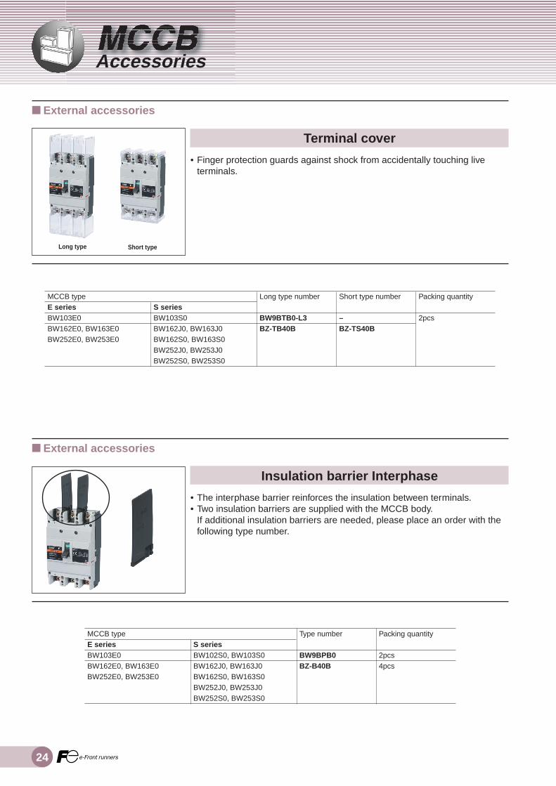
Insulation barrier Interphase
• The interphase barrier reinforces the insulation between terminals.• Two insulation barriers are supplied with the MCCB body.
If additional insulation barriers are needed, please place an order with thefollowing type number.
■ External accessories
Terminal cover
• Finger protection guards against shock from accidentally touching liveterminals.
Long type Short type
■ External accessories
Accessories
MCCB typeE seriesBW103E0BW162E0, BW163E0BW252E0, BW253E0
S seriesBW103S0BW162J0, BW163J0BW162S0, BW163S0BW252J0, BW253J0BW252S0, BW253S0
Long type number
BW9BTB0-L3BZ-TB40B
Short type number
–BZ-TS40B
Packing quantity
2pcs
MCCB typeE seriesBW103E0BW162E0, BW163E0BW252E0, BW253E0
S seriesBW102S0, BW103S0BW162J0, BW163J0BW162S0, BW163S0BW252J0, BW253J0BW252S0, BW253S0
Type number
BW9BPB0BZ-B40B
Packing quantity
2pcs4pcs

25MCCBAccessories
A
Block terminal
This connector screws directly to the standard connectors.
■ External accessories
Flat terminal
• To facilitate connecting work:Additional flat terminals can be attached to 160 to 250A frames.Attach flat terminals according to the screw size and tightening torque asshown in the table below.
MCCB typeE seriesBW162E0BW252E0
BW163E0BW253E0
S seriesBW162J0BW162S0BW252J0BW252S0BW163J0BW163S0BW253J0BW253S0
Type number
BZ-S50B-2252
BZ-S50B-2253
Packing quantity
4pcs
6pcs
MCCB sideScrew SizeM8 × 20
M8 × 20
Torque8 ~ 13N•m
8 ~ 13N•m
Flat Terminal sideScrew SizeM8 × 25
M8 × 25
Torque8 ~ 10N•m
8 ~ 10N•m
■ External accessories
MCCB typeE series–
BW103E0
BW162E0, BW163E0
BW252E0, BW253E0
S seriesBW102S0
BW103S0
BW162J0, BW163J0BW162S0, BW163S0BW252J0, BW253J0BW252S0, BW253S0
Ratedcurrent (A)15 to 5060 to 10015 to 5060 to 100100 to 160
175 to 250
Wiresize (mm2)1.5 to 165.5 to 501.5 to 165.5 to 5042.4 to 1525.5 to 50
TypenumberBW9SSL0B0-052BW9SSL0B0-102BW9SSL0B0-053BW9SSL0B0-103BW9SSL0G0(*)
Packing quantity
3pcs
Note:(*) The Icu decreases to 50% when Block terminals are installed to the power supply side.

26
MCCB typeE seriesBW103E0BW162E0, BW163E0BW252E0, BW253E0
Handle locking device
• This key lock device snaps on to the enable the handle to be locked ineither the OFF position. It can be used either as a handle locking cover or,with the addition of a padlock, as an OFF lock.
• Use a commercially-available padlock. The shackle of the padlock should 4to 8mm diameter.
S seriesBW102S0, BW103S0BW162J0, BW163J0BW162S0, BW163S0BW252J0, BW253J0BW252S0, BW253S0
Type number
BW9Q1B0BW9Q1G0
■ External accessories
Accessories

27MCCBAccessories
A
MCCB typeE seriesBW103E0
S seriesBW102S0, BW103S0
IEC 35mm rail mounting
• Unfication of the external and basic dimensions has expanded the range ofmodels mountable on IEC 35mm rails.
■ External accessories
Type number
BW9PDB0

28
MCCB typeE seriesBW103E0
BW162E0, BW163E0BW252E0, BW253E0
Terminal Connection
Size
Rated current:15 to 50AM5 ×13.5Rated current:60 to 100AM8 ×13.5M8 ×16
Tighteningtorque [N•m]2
5.5
8-13
S seriesBW102S0, BW103S0
BW162J0, BW163J0BW162S0, BW163S0BW252J0, BW253J0BW252S0, BW253S0
Pan-head screw
Hexagonal head bolt
● Terminal Connection/Front mounting, Front Connection• MCCBs and cables according to the screw size and tightening torque as shown in the table below.• To facilitate the connecting work, the following parts are prepared.
Flat terminal : See page 25Block terminal : See page 25
Installation
Screw and Bolt

29MCCBInstallation
I
Arc Space
• When wiring, secure the insulation space as shown in the table below.• To the bare conductors, carry out insulation protection with the insulation taping or the insulation barrier
Interphase in the range as shown in the table below.
MCCB typeE series
BW103E0–
BW162E0BW163E0BW252E0BW253E0
–
–
S series
BW102S0BW103S0
–
BW162J0BW163J0BW252J0BW253J0BW252S0BW253S0
Rated interruptingcapacity (kA)415V AC1530
18
25
36
C1
4040
50
50
50
D1
4545
60
60
60
D2
4545
45
45
45
D1
7575
140
140
140
D2
4595
45
45
45
D1
D2
C1C1
D1
D2
0
Insulation barrierInterphase
Insulation barrierInterphaseInsulation barrier
Interphase
Bare or painted sheet metal insulated bars Bare busbar under voltage
Minimum distance between twoadjacent MCCB
Minimum distance between MCCBand trip, bottom or side panels
Minimum distance between MCCBand front or rear panels

30
Characteristic curves (Line protection)
60A 75A 80A
Multiple of rated current (A)
Op
erat
ing
tim
e (S
)
Multiple of rated current (A)
Op
erat
ing
tim
e (S
)
Multiple of rated current (A)
Op
erat
ing
tim
e (S
)
15A 20A 25A
Multiple of rated current (A)
Op
erat
ing
tim
e (S
)
Multiple of rated current (A)
Op
erat
ing
tim
e (S
)
Multiple of rated current (A)
Op
erat
ing
tim
e (S
)30A 40A 50A
Multiple of rated current (A)
Op
erat
ing
tim
e (S
)
Multiple of rated current (A)
Op
erat
ing
tim
e (S
)
Multiple of rated current (A)
Op
erat
ing
tim
e (S
)
■ E and S series, 2, 3-pole
BW103E0 ,BW102S0 , BW103S0

31MCCBCharacteristic curves (Line protection)
C
100A
Multiple of rated current (A)
Op
erat
ing
tim
e (S
)
.5 .7 1 2 3 4 5 7 10 20 30 50 70100 200300
10 0005 000
2 000
1 000
500
200100
50
20
10
5
2
1.5
.2
.1.05
.02
.01
.005
.002
.001
Multiple of rated current (A)
Op
erat
ing
tim
e (S
)
.5 .7 1 2 3 4 5 7 10 20 30 50 70100 200 300
10 0005 000
2 000
1 000
500
200100
50
20
10
5
2
1.5
.2
.1.05
.02
.01
.005
.002
.001
Multiple of rated current (A)
Op
erat
ing
tim
e (S
)
100A - 125A 150A - 200A 225A - 250A
.5 .7 1 2 3 4 5 7 10 20 30 50 70100 200 300
10 0005 000
2 000
1 000
500
200100
50
20
10
5
2
1.5
.2
.1.05
.02
.01
.005
.002
.001
Multiple of rated current (A)
Op
erat
ing
tim
e (S
)
■ E and S series, 2, 3-pole
BW103E0 ,BW102S0 , BW103S0
BW162E0 , BW163E0 , BW252E0 , BW253E0 ,BW252J0 , BW253J0 , BW162J0 , BW163J0 , BW162S0 , BW163S0 , BW252S0 , BW253S0
32
Dimensions (E and S series)
Ø3.65or M4
2-pole 3-pole
Ø3.65or M4
22
14,5
71
111
55,5
111
55,5
17,5
25
12,5
CLCC
CLCC CLCC CLCC
MCCB MCCB
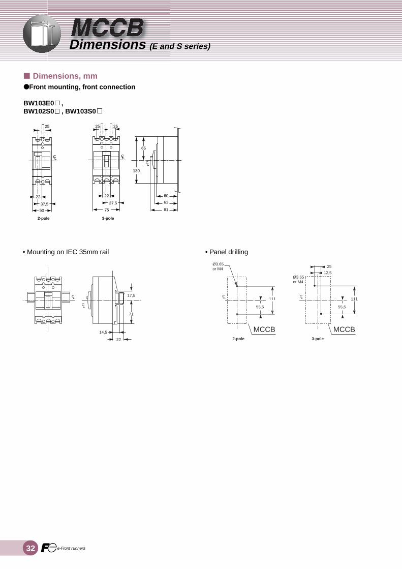
• Mounting on IEC 35mm rail • Panel drilling
■ Dimensions, mm● Front mounting, front connection
BW103E0 ,BW102S0 , BW103S0
25
22
37,5
50
22
37,5
130
65
75 81
63
60
25 25
2-pole 3-pole
CL CLCL
33MCCBDimensions (E and S series)
D
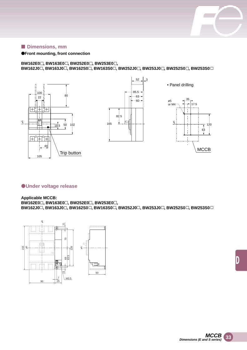
Trip button
5019.5
105
100
2280
44
165
82.5
52 3
85.5
63
60 35
17.5
120
63
MCCB
ø5or M4
102CL CL
• Panel drilling
M3.5
C
C
CL
L
L
725
1111
128
63.5
6970
155
90
60
■ Dimensions, mm● Front mounting, front connection
BW162E0 , BW163E0 , BW252E0 , BW253E0 ,BW162J0 , BW163J0 , BW162S0 , BW163S0 , BW252J0 , BW253J0 , BW252S0 , BW253S0
● Under voltage release
Applicable MCCB:BW162E0 , BW163E0 , BW252E0 , BW253E0 ,BW162J0 , BW163J0 , BW162S0 , BW163S0 , BW252J0 , BW253J0 , BW252S0 , BW253S0

34
Printed in Japan 2005-3 sh 30 FISInformation in this catalog is subject to change without notice.
5-7, Nihonbashi Odemma-cho, Chou-ku, Tokyo, 103-0011, JapanURL http://www.fujielectric.co.jp/fcs/eng
Safety Considerations● For safe operation, before using the product read the instruction manual or user manual that comes with the
product carefully or consult the Fuji sales representative from which you purchased the product.● Products introduced in this catalog have not been designed or manufactured for such applications in a system
or equipment that will affect human bodies or lives.● Customers, who want to use the products introduced in this catalog for special systems or devices such as for
atomic-energy control, aerospace use, medical use, passenger vehicle, and traffic control, are requested to consult the Fuji sales division.
● Customers are requested to prepare safety measures when they apply the products introduced in this catalog to such systems or facilities that will affect human lives or cause severe damage to property if the products become faulty.
● For safe operation, wiring should be conducted only by qualified engineers who have sufficient technicalknowledge about electrical work or wiring.
Printed on 100% recycled paper using soy-based ink