fuji pxf digital temperature controller - coulton temperature controller ... this instrument...
TRANSCRIPT

1
PXF996 × 96 mm PXF5
48 × 96 mmPXF4
48 × 48 mm
Features
21B1-E-0062a
Fast! Compact!
User-friendly!
Digital Temperature ControllerNew-generation PXF Series
Largest bright color LCD in the industry
High speed sampling : 50ms Fast processing : 100ms
Universal input
The best-in-class compact : 58mm depth
Multidrop master fuction (option)

2
Control output indicator Alarm output (DO) indicator
Manual operation indicator
Process value (PV)
Set value (SV)
MV Bar graph
Up key
����Down keyDigit selector
Select key
User key
PID auto tuning indicator
Parameter number
Ramp/soak status
Easy-to-See color LCD! Fast control!
Tallest PV characters in the industry
High contrast, wide viewing
angle
Universal input
15.3 mm
(PXF5: 18.1 mm PXF9: 26 mm)
PXF4
Optimal bright and clear white PV display
������� �� ��
��� �����
��� � � ���������
���������
���������
����������
Multi-zone control��������������
���
���������
Bus-powered USB interface equippedMultidrop master function
Cooperative operation functionSV can be transmitted to multi-PXFs through communication. Synchronous temperature rise control is available in combination with 2-degrees-of-freedom PID.
Directly connectable to PC via USB port with optional cable. No need of power supply to the PXF.
Smart Ramp-Soak up to 64 segments/15 patterns
Simple power monitoring function/preventive maintenance alarm
Position feedback and servo control is available to valve control
Free loader software - user-friendy key operation and easy to � nd parameters.
Parameter copy functionParameter settings can be copied to multi-PXFs simultaneously and easily through communication.
Flow rate 4 to 20 mA DC, etc.
Pressure
1 input
Easy switchover by parameter setting
1 to 5 V DC, etc.
TemperatureThermocoupleRTD
depth:58 mm
���������
���������
���������
������������
����������
3
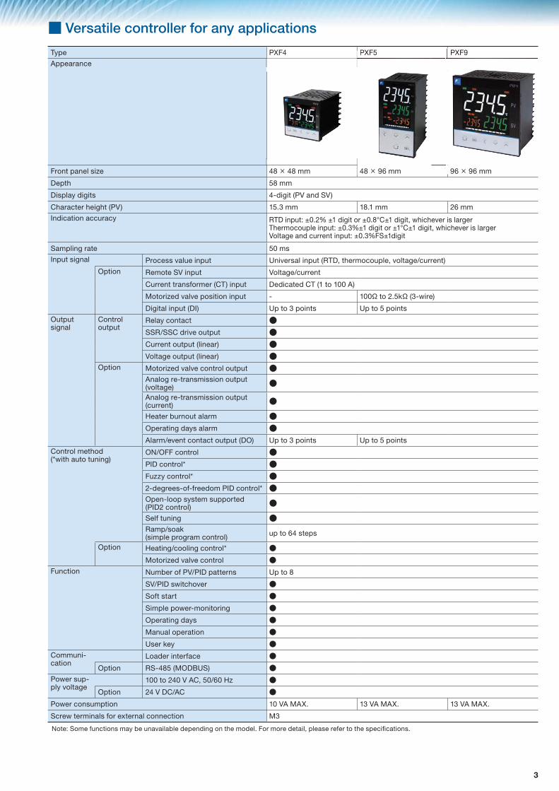
■ Versatile controller for any applications
Type PXF4 PXF5 PXF9
Appearance
PXF5 PXFPXF99
Front panel size 48 × 48 mm 48 × 96 mm 96 × 96 mm
Depth 58 mm
Display digits 4-digit (PV and SV)
Character height (PV) 15.3 mm 18.1 mm 26 mm
Indication accuracy RTD input: ±0.2% ±1 digit or ±0.8°C±1 digit, whichever is largerThermocouple input: ±0.3%±1 digit or ±1°C±1 digit, whichever is largerVoltage and current input: ±0.3%FS±1digit
Sampling rate 50 ms
Input signal Process value input Universal input (RTD, thermocouple, voltage/current)
Option Remote SV input Voltage/current
Current transformer (CT) input Dedicated CT (1 to 100 A)
Motorized valve position input - 100� to 2.5k� (3-wire)
Digital input (DI) Up to 3 points Up to 5 points
Output signal
Control output
Relay contact ●SSR/SSC drive output ●Current output (linear) ●Voltage output (linear) ●
Option Motorized valve control output ●Analog re-transmission output (voltage) ●Analog re-transmission output (current) ●
Heater burnout alarm ●Operating days alarm ●Alarm/event contact output (DO) Up to 3 points Up to 5 points
Control method(*with auto tuning)
ON/OFF control ●PID control* ●Fuzzy control* ●2-degrees-of-freedom PID control* ●Open-loop system supported(PID2 control) ●
Self tuning ●Ramp/soak(simple program control) up to 64 steps
Option Heating/cooling control* ●Motorized valve control ●
Function Number of PV/PID patterns Up to 8
SV/PID switchover ●Soft start ●Simple power-monitoring ●Operating days ●Manual operation ●User key ●
Communi-cation
Loader interface ●Option RS-485 (MODBUS) ●
Power sup-ply voltage
100 to 240 V AC, 50/60 Hz ●Option 24 V DC/AC ●
Power consumption 10 VA MAX. 13 VA MAX. 13 VA MAX.
Screw terminals for external connection M3
Note: Some functions may be unavailable depending on the model. For more detail, please refer to the speci! cations.

4
Parameter setting is available using the front keys or a PC with loader software.
1 On/Off control
3 Fuzzy control with auto tuning
5 Open-loop supported PID2 control
When process value (PV) is below the set value (SV), output is turned on and the heater is energized as shown below. When PV is above SV, output is turned off and the heater is de-energized. In this way, output is turned on/off repeatedly with respect to the SV to keep the temperature constant. This method of control is called “on/off action (2-position action)”* When “0” is assigned to parameter P, the on/off action will be selected.
Fuzzy control is used to suppress overshoot so that the response to external disturbance is improved. By monitoring PV, overshoot is sup-pressed with startup time remaining unchanged. Also, disturbance can be settled quickly.● Comparison between fuzzy control and conventional control
Reduces overshoot in the processes where the control target is turned off and then on again.
Typical PID control.Overshoot may occur due to external disturbance.
This function achieves stable control against external disturbances, while suppressing overshoot and undershoot at startup or at SV change.
At power up, SV change, or during external disturbance, tuning is made automatically so that the PID parameters are re-optimized.
Note: For some objects of control, PID values can not be optimized.
■ Advanced control functions
Standard functions
1 On/Off control
2 PID control with auto tuning
3 Fuzzy control with auto tuning
4 2-degrees-of-freedom PID control with auto tuning
5 Open-loop supported PID2 control
6 Self tuning
7 Ramp soak function (simple program control)
Optional functions
1 Heating/cooling control with auto tuning
2 Motorized valve control
2 PID control with auto tuning
4 2-degrees-of-freedom PID control with auto tuning
6 Self tuning
"#$
&'+��+#+
7;
7��
&���
��������<=���<��#+�#<��>�7;?7����<�#��
��@���
7@�+=������+���+�����#+������<+
���@���
Conventional controlFuzzy control
7@�+=�����E+���+�����������������������#+������<+
7@�+=�����E+���+�����������������������#+������<+
���@������@���
���<++�@���
�G �G
�G
PV
"#$
������������������ ������������������������α�����β)���<++�@���
"#$
������������������ ����������������� ���α�����β)���<++�@���
"#$
�G
�G
������������������
���<++�@���
7@�+=����#+�<��������
�G
�7;
��J��+����'���<�������K�#�$��
7��
���+ ���+
7��
�G
������������
Set value change
External disturbance
Power on

5
M
���+�#��+�$$�Q�����#��J#���
7���#��+�$$�Q�<��+�#��J#���
��$$����+J#�<=
�J#�<=#�Y��$$�Z�;��$����<�#��[#���Z�E@�+��<�#��
G��@�<�������<�$$����������
"$�������+�+��
�����#��@��@ \����#]��@��@
�����J���
&���J���
��$$�����[#���
^#��<���#�#���
�����#��@��@ G��@���+#�#���+#Y����_�+#+���<`
7 Ramp soak function (simple program control)
Energy saving in livestock barns
Heating/cooling control of air conditioner
Function of automatically changing the set point value with the elapsing of time, in accordance with the preset pattern, as shown below. This function is capable of programming 15 pro-gram patterns. Max.64 steps.
PID auto tuning
1 Heating/cooling control (option)
PID parameters are automatically set by the controller's measurement and computation function. This instrument provides 2 types of auto-tuning func-tions; the standard type (auto-tuning with SV used as reference) and the low SV type (auto-tuning with the value 10% below SV used as reference).
Note: For the cooling side proportional band, set a coef! cient with respect to the heating side proportional band. (ON-OFF control if coef! cient is 0.)
(a) Standard type (b) Low-PV type
By a single controller, both heating and cooling control output are obtained.
■OperationStart/stop/suspension can be performed by various ways (a user key, parameter set-ting, digital input, or communication)
■Basic functions① [h · min] or [min · s]② Guarantee soak③ Repeat action④ PV start⑤ Delay start⑥ Power failure recovery
■Number of steps and patterns
Steps Patterns64 132 216 48 8
2 Motorized valve control (option)
· Position feedback control based on motorized valve position signal· Servo control without valve position signal
Temperature control of plastic molding machine Start/stop of auto tuning can be commanded externally.
�G ���$����>���+��+��� �������+ \����� �+��+��+���
+������� Z�������� +���������Z��������� +���������Z��������� +���������Z��������
"\� "\��"\+ "\�+ "\��
"\�+"#$
�G�
�G��
�G��
�G�
�G��
�G��
�G�
�G��
�G��
�G�
�G��
�G��
�G��
�G��
�G��
�G��
+���� +����
�G
�����<
7;Z������7��Z�E+�
��E���#@�������
"$�������#����
"=�$�<����
��E
�G�
�G��
�G���G�
�G��
�G��
�G���G��
"#$
"$��������#+?>�����������#+�<����������'�+��#�Y���=����������=�@#�Y��Y���#�����^<�#���+����?�+�#�Y�<�����<�$$������������'�
[Ramp soak function]
�#Y#����#����E�$��+�����<�#���<�$$���
��
�@��
�
Temperature gradient control of furnaceFor control in a heat pattern
7�� 7��
7; 7;7;����
7�����
"̂�+����"̂�<�$�����#��
"̂����_����+���`
�G�_���<++�@���`
7;�7����<�#������<������
_ ���
����
����
���`
���@����_�G`
7�� 7��
7; 7;
�G����
7;����
7�����
"̂�+����
���@����_�G`
"̂�<�$�����#��"̂����_����+���`
�G�_���<++�@���`
7;�7����<�#������<������
_ ���
����
����
���`
�#Y#����#����^�������#�Y�<�$$���
7;Z����7��Z�+���
"��#�Y
�G
�G
7; 7;��E ��E
"$�������#����
"$�������#����
Heater
"$�����������$
\���#�Y�$�<=#�E�J�$���#��+
Heating side Cooling side
Deviation(-)
Deviation(+)
Coefficient 0.5
Coefficient 1.0
Coefficient 2.0
Output
Set value (SV)Cooling side
proportional bandHeating side
proportional band
Proportional band (P)
Heating side Cooling side
Deviation (-)
Deviation(+)
Output
Set value (SV)
Dead bandOverlap
band
M
Inverter
#��+=�
"��=���
\������>�<���#�Y�>�� �������������
^�E
&������J��+����'
�������������
E��$��$������
"$�������#�����+#Y���
������+=�
● Both heating and cooling are controlled with only one temperature controller utilizing its 2 control outputs.● Power consumption can be curbed by controlling a cooling fan motor with inverter.

6
■ Even more functions which extend the possibilities of temperature controllerStandard functions
1 SV and PID selection
2 Soft start
3 Simple power-monitoring
4 Operating days alarm
Optional functions
1 Re-transmission output
2 Remote SV input
3 Heater burnout alarm
4 Alarm output
5 Digital input
6 RS-485 Communication
1 SV and PID selection
Allows you to register up to 8 sets of SV setting and PID set-ting, and to switch among them, enabling optimum PID set-ting for changing process, materials, or PV. You can perform SV selection only, or PID selection only.
2 Soft start
This function controls the maximum output produced when turning on the equipment (including the temperature controller).This function is useful for effects such as suppressing the heat-er output during equipment startup, or lightening the load.
Calculates the energy consumption by connecting an op-tional current transformer. (See page 10.)
A cost corresponding to one temperature sensor can be re-duced just by connecting a PV transfer signal to a recorder.• Output signal (any one of the followings): 0 to 20 mA DC, 4 to 20 mA DC, 0 to 5 V DC, 1 to 5 V DC, 0 to 10 V DC, 4 to 10 V DC• Output type: process value (PV), set value (SV), control output (MV), or PV-SV (DV)
3 Simple power-monitoring 4 Operating days alarm
1 Re-transmission output (option)
SV can be con! gured externally.• Input signal (any one of the followings): 0 to 5 V DC, 1 to 5 V DC, 0 to 10 V DC, 0 to 20 mA DC, 4 to 20 mA DC• Input impedance: About 1 M�
2 Remote SV input (option)
① Operating days indication
② Operating days alarm output
This function is useful for preven-tive maintenance because it let you know the appropriate time for maintenance work.
���������������_\G` \G�J#�=����+�>��+����
_�#$#��`MV with soft start
��>��+������������+��@���
��J��7;�����#Y#����#�����7;
����>��+�����+���#$
�
&��������
G����YZ�+�#$����@����+���'����������������+��_����G`������Z�@����$�+�����'��"
[#�=��" [#�=�����"
^�
�������$���+��#�Y
�����@����Y�_G`����
��������������
�+�#$����@����Y��
×
�����<�����
0.2����$���+��#�Y
7;��#$�
�+�#$����<������
&���������
���
\�+��+��<�����<�����
�+�#$����@����Y
G����YZ�+�#$����@����+���'����������������+��_����G`������Z�+�#$����@����+���'����������������+��_����^`
�����@����Y�_G`�
�"�#����
��������������
����
�"
���Y'�<��+�$��#���[=
����$���+��#�Y
^�
�����<�����
���Y'�<��+�$��#���[=
×
^���$
^���$�#+���#YY���J=���=����������'+���<=��=�@����'���+��
G����Y?<�����
Recorder PHR
�������<�������+#Y���
^����J���Y�������_^�E`
"$�������#����
��'�
7#�
&���
PV transfer output
����$�������_�G`
"$�������#����
��������������
������G���
�K��<�
����^ ����� ����� ����� �����"=��$��������>��<=�<���#+�+���'��=�+K��<��
��E���#@�������
�G�+J#�<=#�Y
���
����+J#�<=#�Y
�G�+J#�<=#�Y
����+J#�<=#�Y
��
������
����
������
��
�����
��E

7
Up to 3 points
4 Alarm output (option)3 Heater burnout alarm (option)
• A current transformer (CT) is required. (See page 10, optional items).• The power supply voltage and the alarm action point need
to be con! gured beforehand.• Available only for single-phase heater • Not available when using thyristor phase angle control
• Programless communication PXF can be connected with PLC without a program.
• High-speed communication (user address mapping function) You can make a list of your most necessary parameters (max. 32 words) to quickly acquire those data at a time. Communication speed: max. 115.2 kbps
• PXFs can be connected with PC, programmable operation display, or PLC.
6 RS-485 Communication (option)
For SV changeover, AT startup, timer startup, program se-lection, start/stop/reset, PID changeover, etc.
5 Digital input (option)
����
��
��
���� �� ��+ -
_�"`
��J��+����'�������� ��G�^�Q���?���&]
�����������+>��$�
��<��#<�>����<
&���
"=�$�<����
��<���$�Y��#<�+J#�<=
&����������������$�������
��J��+����'
����������������
��
�
[#������=����_�=���Y=�=���#���"`
[#����������_J#�=���������#�'`
[Example of PXF5/PXF9]
^���$��'� ^<�#����#�Y��$
������#$#����+�����@���
��J���#$#����+�����@���
������#$#����+�����@����_J#�=�=���`
��J���#$#����+�����@����_J#�=�=���`
������#$#���@#��#���_J#�=�=���`
��J���#$#���@#��#���_J#�=�=���`
�����������J���#$#�+��@#��#���_J#�=�=���`
E��Y������������J���#$#�+��@#��#���_^�\?��#�������������#��`
������#$#���@#��#��
��J���#$#���@#��#��
�����������J���#$#�+��@#��#��
E��Y������������J���#$#�+���+�����@���
E��Y������������J���#$#�+��@#��#��
E��Y�������#$#����+�����@����������J���#$#���@#��#��
E��Y�������#$#���@#��#���������J���#$#����+�����@���
�G^��
^���G
^���G
^���G
^��
�G�G
^��
�G�G
^��
�G�G
^��
�G�G
�G^�� ^�
�G
^�
�G^��
�G
^��
�G ^�
�G
^�� ^�
�G
^�� ^��
�G�G
^�� ^��
�G�G
�G
^�� ^��
�G
^�
+���
��@
���
����
�$+
Deviation alarms
Range alarms
��E���#@�������
"$�������#����
"$�������#����
7@�
�#Y#����#�����G�<=��Y�<�$$���
Changeover of 4 set values (front SV, SV1 to SV3) can be commanded externally.��E
��E���#@�������
��E
�#Y����<��@���E�� ���_\7����`
�������
\�������<��������+<���<����
������� ��������
���Y��$$���������#����#+���'
���Y��$��++�=�+��<�$$��#<��#��
"$�������<������
E>��J�+����#�Y��@#<
PXF4
PXF5PXF9
30001 PV
30002 SV(Read)
30003 DV
30004 MV1
.
.
.
.
.
.
40003 SV(Write)
40004 STBY
40005 AT
40006 P
40007 I
40008 D
.
.
.
.
.
.
30001 PV
30002 SV(Read)
40003 SV(Write)
30004 MV1
40006 P
40007 I
40008 D
.
.
.
.
.
.
– –
– –
– –
Address Parameter
Address Parameter
Max.32 words

8
■ Speci� cations
■ General speci� cationsPower supply voltage 100 (-15%) V to 240 (+10%) V AC, 50/60Hz
24 V DC/AC (±10%)
Power consumption Type 100 to 240 V AC 24 V DC/AC
PXF4 10 VA MAX. 3 VA MAX.
PXF5 & 9 13 VA MAX. 8 VA MAX.
Insulation resistance 20 M� or more (at 500 V DC)
Withstand voltage Power source ⇔ all terminals: 1500 V AC for 1 minRelay contact output ⇔ all terminals: 1500 V AC for 1 minBetween others: 500 V AC for 1 min
■ Process value inputNumber of input 1
Input setting Programmable scale
Input signal See Table 1(Universal input: thermocouple/RTD/voltage/current)
Standard measurement range and input type
See Table 1
Indication accuracy(at Ta = 23°C)
• Thermocouple input: either ±1°C ±1 digit or ±0.3% ±1 digit of indicated value, whichever is larger*except: Thermocouple B: 0 to 400°C: no accuracy assurance Thermocouple R: 0 to 500°C: ±3°C ±1 digit All thermocouples: -200 to -100°C: ±2°C ±1 digit• RTD input: ±0.8°C ±1 digit or ±0.2% ±1 digit of indicated value, whichever is larger• mV input, voltage input, current input: ±0.3%FS ±1 digit
Temperature effect on sensitivity
±0.3%FS/10°C
Indication resolution See Table 1
Sampling rate 50 ms
Input impedance • Thermocouple, mV input: 1 M� or more• Current input: 150 � or less (built-in diode)• Voltage input: About 1 M�
Variation by signal source resistance
• Thermocouple, mV input: ±0.3%FS ±1 digit per 100 �• Voltage input: ±0.3%FS ±1 digit per 500 �
Allowable wiring resis-tance
• RTD: 10 � MAX. (per wire)
Allowable input voltage: • DC voltage input: within ±35 V• Current input: within ±25 mA• Thermocouple, RTD, mV input: within ±5 V
Noise reduction ratio • Normal mode: 40 dB (50/60 Hz)• Common mode: 120 dB (50/60 Hz)• Between input and power supply: ±1°C at 220 V AC, 50/60 Hz
Input correction: (a) User adjustment: ±50%FS for each of zero and span point(b) Process value shift: ±10%FS(c) Input ! lter: 0.0 to 120.0 s (! lter OFF if set at 0.0)(d) Square root extraction: -0.1 to 105% (OFF if set to -0.1%)
Overrange ·underrange
Out of the range between -5 to 105% of FS(accuracy not guaranteed between -5 and 0, and between 100 and 105%FS)*except: • JPt (-199.9°C to 600.0°C) input: • Pt (-200°C to 850°C) input: • 0 to 10 V DC input: • Thermocouple E: Out of the range between -5 to 102% of FS
■ Remote SV input (option)Number of input 1
Input signal Voltage: 0 to 5 V DC/1 to 5 V DC/0 to 10 V DCCurrent: 0 to 20 mA DC/4 to 20 mA DC (an external 250-ohm resistor is required for current input)
Input impedance Approx. 1 M�
Sampling rate 50 ms
■ Current transformer (CT) input (option)Input type Single phase CT, 1 point
For 1 A to 30 A: CTL-6-S-HFor 20 A to 100 A: CTL-12-S36-8
Range of detected current 1 A to 100A
Detected current accuracy Setpoint ±5%FS
Detected current resolu-tion
0.1 A
ON time necessary for detection
300 ms MIN.
■ Digital input (DI) (option)Number of point up to 5 (PXF4: up to 3)
Speci! cation No-voltage contact or transistor input
Contact capacity: 5 V DC, about 2 mA (per point)
Input judgment: ON voltage: 2 V DC or lowerOFF voltage: 3 V DC or higher
Sampling pulse width 50 ms MIN.
Function Remote mode selection, SV changeover, control standby, AT startup, timer startup, alarm unlatch, program selection, start/stop/reset, PID switching (normal/reverse), etc.
■ Valve position feedback signal (Potentiometer) input (option)Model PXF5 and PXF9 (not available for PXF4)
Resistance range 100 � to 2.5 k� (three-wire)
Resolution 0.5%FS
Accuracy ±1.0%FS
Temperature effect on sensitivity
±0.5%FS/10°C
Burnout function Not provided
■ Control outputNumber of point Up to 2 (2 points: Heating/cooling control)
TypeSelect among ① to ⑥ below
① Relay contact output (SPST) • Proportional cycle: 1 to 150 s • Contact structure: 1 SPST contact *SPST: single pole single throw • Contact capacity: 250 V AC/30 V DC, 3 A (resistive load) • Minimum ON/OFF current: 10 mA (5 V DC) • Mechanical life: 20 million operations MIN. (100 operations/min) • Electrical life: 100,000 operations MIN. (rated load)② Relay contact output (SPDT) • Proportional cycle: 1 to 150 s • Contact structure: 1 SPDT contact *SPDT: single pole double throw • Contact capacity: 250 V AC/30 V DC, 5A (resistive load) • Mechanical life: 50 million operations MIN. (100 operations/min) • Electrical life: 100,000 operations MIN. (rated load)③ SSR/SSC drive output • Proportional cycle: 1 to 150 s • ON voltage: 12 V DC (between 10.7 and 13.2 V DC) • OFF voltage: 0.5 V DC or lower • Maximum current: 20 mA DC • Load resistance: 600 � MIN.④ Current output (0 to 20 mA DC/4 to 20 mA DC) • Accuracy: ±5%FS • Load resistance: 500 � MAX.⑤ Voltage output (0 to 5 V DC/1 to 5 V DC/0 to 10 V DC/2 to 10 V DC) • Accuracy: ±5%FS • Load resistance: 10 k� MIN.⑥ Motorized valve control output • Contact structure: 2 SPST contacts without interlock circuit
*SPST: Single Pole Single Throw • Contact capacity: 250 V AC/30 V DC, 3 A (resistive load) Minimum ON/OFF current: 100 mA (24 V DC) • Mechanical life: 20 million operations MIN. (100 operations/min) • Electrical life: 100,000 operations MIN. (rated load)
■ Alarm output (DO) (option)Number of outputs Relay contact output: up to 5 (shared common) PXF4: up to 3
up to 3 (independent common) PXF4: up to 2
Output speci! cations Relay contact outputContact structure: 1 SPST contact *SPST: single pole single throwContact capacity: 250 V AC/30 V DC, 1A (resistive load)Minimum ON/OFF current: 10 mA (5 V DC)Mechanical life: 20 million operations MIN. (100 operations/min)Electrical life: 100,000 operations MIN. (rated load)
Output functions Alarm output (see "Alarm function"), main unit control mode output, program status output, control output 1 and 2, etc.
Output cycle 100 ms
■ Re-transmission output (option)Number of point 1
Type Current/voltage output (0 to 20 mA DC/4 to 20 mA DC/0 to 5 V DC/ 1 to 5 V DC/0 to 10 V DC/ 2 to 10 V DC)• Guaranteed output range: 0 to 21mA DC/0 to 10.5 V DC• Accuracy: ±0.2%FS (±5%FS at 1 mA or smaller)• Resolution: 10,000 MIN.• Load resistance: 500 � MAX. (current), 10 k� MIN. (voltage)
Output cycle 100 ms
Output contents PV, SV, DV, MV
Additional function Scaling function
■ Display unitType LCD (with backlight)
Indication contents Process value indication: 11-segment, 4-digit [white]Setpoint indication: 11-segment, 4-digit [green]Screen No. indication: 7-segment, 4-digit [orange]Indication status: 42 indicator lamps
Luminance setting possible (4 steps)
■ Setting sectionType and number of keys Sheet type keys (with emboss), 5 keys
■ Control functionsON/OFF control Refer to page 4.
PID control • Dual control (heating/cooling)• PID parameters determination: Auto tuning
Fuzzy PID control • Dual control (heating/cooling)• PID parameters determination: Auto tuning
Self tuning control Refer to page 4.
PID2 control • Dual control (heating/cooling)• PID parameters determination: Auto tuning
2-degrees-of-freedom PID • PID parameters determination: Auto tuning
Position proportional PID (servo) with position feedback
• Full stroke time: 30 seconds MIN. (not available for PXF4)
■ Control parametersProportional band (P) 0.1% to 999.9%
Integration time (I) 0 to 3200 s (invalidated when I = 0)
Differential time (D) 0.0 to 999.9 s (invalidated when D = 0)
Control cycle 100 to 900 ms (in 100 ms), 1 to 99 s (in seconds)
Anti-reset windup 0 to 100% of measurement range
Hysteresis band 50% of measurement range (at 2-position control only)
Number of SV and PID patterns
8: Changed by any of parameter setting, digital input, communica-tion, user function keying, zone change.
Out of the range between -2% to 105% of FS

9
■ StructureMounting method Panel mount
External terminals Screw terminals, M3
Case • Material: ABS, PPO• Non-combustibility grade: UL94V-0 equivalent• Color: Black
Protection structure • Panel front side: IP66, NEMA-4X equivalent(When the panel is mounted using our genuine packing.Not water-proof if mounted closely together.)
• Body: IP20 equivalent (slits on top and bottom)• Terminals: IP00 equivalent. Terminal cover can be provided optionally.
Dimensions Refer to page 14.
Weight PXF4: approx. 100 g, PXF5: approx. 170 g, PXF9: approx. 220 g
■ User customize function and Program (ramp/soak) functionNumber of program steps
64 steps x 1 patterns,32 steps x 2 pattern,16 steps x 4 pattern, or8 steps x 8 patterns(1 step = 2 segments)
Control option: Control by digital inputStatus output by digital output
Basic functions [1] Segment time can be set in "Hour, Minutes" or "Minutes, Seconds"② Guarantee soak③ Repeat action④ PV start⑤ Delay start⑥ Power restoring function
Memory backup EEPROM
■ User functionsUser key assignment Auto/Manual change, Standby ON/OFF change, remote SV
change.
■ Password function3-level password
■ Simple power-monitoring function and operating days alarmSimple power-monitoring function
• By connecting a current transformer (to be prepared sepa-rately), electric power consumption of the heater can be displayed. (Electric power is calculated based on the ! xed voltage value you set.)
• Current detector(CT) is to be prepared separately (see page 10.)• Current detection range: 1 A to 100 A
Operating days alarm • Indicates the number of days the controller has been oper-ated and activates alarm output (optional) when it exceeds the setpoint.
• Useful for preventive maintenance because it let you know the appropriate time for maintenance work.
■ Processing at power failureMemory protection Protect by non-volatile memory
■ Self-diagnosisMethod: Program error supervision by watchdog timer
Table 1 input type and range
Input type Code (PvT)Measurement range
[°C]Minimum input increment [°C]
Pt 100 PT1 0.0 to 150.0 0.1PT2 0.0 to 300.0 0.1PT3 0.0 to 500.0 0.1PT4 0.0 to 600.0 0.1PT5 -50.0 to 100.0 0.1PT6 -100.0 to 200.0 0.1PT7 -199.9 to 600.0 0.1PT8 -200 to 850 1
DC voltage 0 to 5 V DC 0-5V
-1999 to 9999 (Range where scaling is
allowed)-
1 to 5 V DC 1-5V0 to 10V DC 0-102 to 10V DC 2-10
0 to 100mV DC MVDC current 0 to 20mA DC 0-20
4 to 20mA DC 4-20
Input type Code (PvT)Measurement range
[°C]Minimum input increment [°C]
Thermocouple J J1 0.0 to 400.0 0.1J2 -20.0 to 400.0 0.1J3 0.0 to 800.0 0.1J4 -100 to 1000 1
K K1 0 to 400 0.1K2 -20.0 to 500.0 0.1K3 0.0 to 800.0 0.1K4 -200 to 1300 1
R R 0 to 1700 1B B 0 to 1800 1S S 0 to 1700 1T T1 -199.9 to 200.0 0.1
T2 -199.9 to 400.0 0.1E E1 0.0 to 800.0 0.1
E2 -150.0 to 800.0 0.1E3 -200 to 800 1
L L -100 to 850 1U U1 -199.9 to 400.0 0.1
U2 -200 to 400 1N N -200 to 1300 1W W 0 to 2300 1
PL-II PL-2 0 to 1300 1
■ Control modeMode Auto/Manual/Remote
*During 2-position control in Manual mode, 2-position manual operation with MV = 100% or 0% is operated.
Mode changeover: • Auto <=> Manual: Balanceless・bumpless• Auto/Manual→Remote: Balance・bumpless• Auto/Manual→Remote: Balance・bumpless
■ Alarm functionNumber of alarm setting points
Up to 5 (depends on the number of DO)
Alarm type Process value (upper limit/lower limit, absolute/deviation, range), main unit error, etc.(non-excitation, delay, latch, timer function option provided)
Heater current alarm function (optional)
*Current detector(CT) is to be prepared separately (see page 10.)
Detectable range 1 A to 100 A
Detected current reso-lution
0.1 A
Setting resolution 0.1 A
Hysteresis 0.0 to 100.0 A
■ RS-485 communication (option)No. of points 1
Physical speci! cations EIA-485
Protocol Modbus-RTU
Communication method Half-duplex bit serial, asynchronous communication
Code type Data length: 8 data bits. Parity: Odd, even, none.
Baud rate 9600 bps, 19200 bps, 38.4 kbps, 115.2 kbps
Connection Up to 32 units connectable including multidrop master func-tion
Communication distance
Up to 500 m (total connection length)
Additional functions • Cooperative operationThe function in which slave devices can be operated via master device by connecting several temperature control-lers.
• Programless communicationThe function in which a temperature controller can be con-nected to a PLC without program.Supported PLCs: Mitsubishi PLC Q series Siemens PLC S7 series
■ Operation and storage conditionsOperating temperature -10°C to 50°C
Storage temperature -20°C to 60°C
Operating/storage humidity
90%RH or less (Non condensation)
Warm-up time 30 min MIN.
Vibration during transportation: 9.8 m/s2 (1 G) or less
Impact during transportation: 294m/s2 (30 G) or less

10
����<#>#<��#��Z��^�������^��"'�Z��"������&
����<�#���#+��@�#��������'�>���+#�Y���=�+����=���������������+��J=���=�=����#+�<�������������+#�Y��='�#+�����=�+���Y��<�������
����<#>#<��#��Z����^�������^��"'�Z��"����������
15
7.5
30
40
M3, depth 4
409
ø12
30 ø2.36
10
257
2.5
10.5
ø3.5
30
40
2.8
21
15
ø5.8
�����_������$$`
���
\����#�Y�>��$�_���@#���J#�=���� `
\����#�Y����<��
[=���=�������=#<��++�#+���$$
\����#�Y�+<�J+�_ ��<+`
[����#Y=����<�#�Y
��� �����<�����
■ ORDERING CODE
�#Y#�� ��<#>#<��#��+
�� ����������������������������������������!"���������#�$%&'
�
��
�
��
�
��;���Z�;����@�#�����>����=���=�<������Q����Q����Q��E�Q�����;����Z�[=���+#�Y�<������>����=��$����G�#����Q������������=$��+#+��������=�#�������$#����;����Z�[=���+#�Y��=��"�#�����>���=����������������$Q������������$��������>���#��#���=���=�<���
������������+#]�[���&� ��×� ��$$� �����������������E��'�<����<��_���"`�;���E��'�<����<��_���"`�;�����E���#@��������������������G����Y�������������������������;��E��'�<����<��_���"`��E���#@��������������������G����Y�������E�����+$#++#����������_<�����`E�����+$#++#����������_@����Y`�E@#+#���<����^���$��������;�����#������#��+����#��+����#��+�_#��������<�$$��`���J��+����'�@����Y?#�+���<�#���$������������� ��G�^�Q� ����+�¡���Y�#+=�#�+���<�#���$������������ ��G�^�Q���Y�#+=�#�+���<�#���$������������ ��G�^�Q��=#�+�¡���Y�#+=�#�+���<�#���$������ �G�^�?��Q� ����+�¡���Y�#+=�#�+���<�#���$������ �G�^�?��Q���Y�#+=�#�+���<�#���$������ �G�^�?��Q��=#�+�¡���Y�#+=�#�+���<�#���$������7��#���;��E�� �����$$��#<��#���#Y#����#�����_��`E�� ���<�$$��#<��#���¢��#Y#����#�����_��`E�� ���<�$$��#<��#���¢�E$����G�#������;�����E�� �����$$��#<��#���¢��"�#������;�����
��� ^
^����
£^���E��
��\
£G[^��
£\�G¤
��
��� �#Y#�� ��<#>#<��#��+
�� ����������������������������������������!"���������#�$%&'
�
��
�
��
�
��
������������+#]�[���&� ��×� ��$$� �����������������\����#]��@��@�<��������������_J#�=�����#����`������������������;���E@#+#���<����^���$��������;�����#������#��+����#��+�_#��������<�$$��`���J��+����'�@����Y?#�+���<�#���$������������� ��G�^�Q� ����+�¡���Y�#+=�#�+���<�#���$������������ ��G�^�Q���Y�#+=�#�+���<�#���$������������ ��G�^�Q��=#�+�¡���Y�#+=�#�+���<�#���$������ �G�^�?��Q� ����+�¡���Y�#+=�#�+���<�#���$������ �G�^�?��Q���Y�#+=�#�+���<�#���$������ �G�^�?��Q��=#�+�¡���Y�#+=�#�+���<�#���$������7��#���;���#Y#����#�����_���Q��Q��`E�� ���<�$$��#<��#���¢��#Y#����#�����_��`�
��� ^
"
£�
��
£G
[^��
£�G
��
���
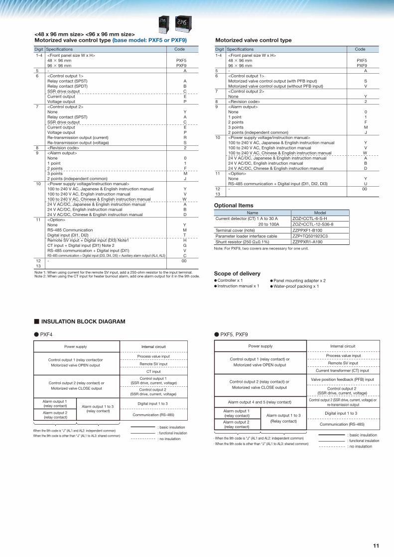
Optional ItemsName ModelCurrent detector (CT) 1 A to 30 A
20 A to 100AZOZ*CCTL-6-S-HZOZ*CCTL-12-S36-8
Terminal cover ZZPPXR1-A230Parameter loader interface cable ZZP*TQ501923C3Shunt resistor (250 �±0.1%) ZZPPXR1-A190Panel mounting adapter for replacement from PXR7 to PXF4 ZZP*TQ502732C1
Panel mounting adapter for replacement from PXR7 to PXF4 (ZZP*TQ502732C1)
Outline diagram of optional items
Panel mounting adapter
Current detector (CT)
How to install PXF4 with the adapter
11
�#Y#�� ��<#>#<��#��+
�� �*+����������*+� �*+��������������������������������������!"���������#�$%&,����$%&*'
�
��
�
��
�
��
;���Z�[=���+#�Y�<������>����=��$����G�#����Q������������=$��+#+��������=�#�������$#����;����Z�[=���+#�Y��=��"�#�����>���=����������������$Q������������$��������>���#��#���=���=�<���
������������+#]�[���&� ��×����$$���×����$$� �����������������E��'�<����<��_���"`E��'�<����<��_���"`��E���#@��������������������G����Y�������������������������;��E��'�<����<��_���"`��E���#@��������������������G����Y�������E�����+$#++#����������_<�����`E�����+$#++#����������_@����Y`�E@#+#���<����^���$��������;�����#������#��+����#��+����#��+�_#��������<�$$��`���J��+����'�@����Y?#�+���<�#���$������������� ��G�^�Q� ����+�¡���Y�#+=�#�+���<�#���$������������ ��G�^�Q���Y�#+=�#�+���<�#���$������������ ��G�^�Q��=#�+�¡���Y�#+=�#�+���<�#���$������ �G�^�?��Q� ����+�¡���Y�#+=�#�+���<�#���$������ �G�^�?��Q���Y�#+=�#�+���<�#���$������ �G�^�?��Q��=#�+�¡���Y�#+=�#�+���<�#���$������7��#���;��E�� �����$$��#<��#���#Y#����#�����_��Q����`E$����G�#�����¢��#Y#����#�����_���`�;���"�#�����¢��#Y#����#�����_��`�;����E�� ���<�$$��#<��#���¢��#Y#����#�����_��`E�� ���<�$$��#<��#���¢��#Y#����#�����_���Q��� Q����`�¢�^��#�#��'�����$��������_^� Q�^��`
�
�#Y#�� ��<#>#<��#��+
����������������������������
�
��
�
��
�
��
������������+#]�[���&� ��×����$$���×����$$� �����������������\����#]��@��@�<��������������_J#�=�����#����`\����#]��@��@�<��������������_J#�=��������#����`������������������;���E@#+#���<����^���$��������;�����#������#��+����#��+����#��+�_#��������<�$$��`���J��+����'�@����Y?#�+���<�#���$������������� ��G�^�Q� ����+�¡���Y�#+=�#�+���<�#���$������������ ��G�^�Q���Y�#+=�#�+���<�#���$������������ ��G�^�Q��=#�+�¡���Y�#+=�#�+���<�#���$������ �G�^�?��Q� ����+�¡���Y�#+=�#�+���<�#���$������ �G�^�?��Q���Y�#+=�#�+���<�#���$������ �G�^�?��Q��=#�+�¡���Y�#+=�#�+���<�#���$������7��#���;��E�� ���<�$$��#<��#���¢��#Y#����#�����_��Q����Q����`�
��������
^
^����
£^���E��
��\
£G
[^��
£\"&¦G�
��
���
��������
^
�G
£�
��\
£G
[^��
£�
��
���
Optional ItemsName Model
Current detector (CT) 1 A to 30 A ZOZ*CCTL-6-S-H 20 to 100A ZOZ*CCTL-12-S36-8
Terminal cover (note) ZZPPXF1-B100Parameter loader interface cable ZZP*TQ501923C3Shunt resistor (250 �±0.1%) ZZPPXR1-A190
Note: For PXF9, two covers are necessary for one unit.
Scope of delivery●Controller x 1● Instruction manual x 1
●Panel mounting adapter x 2●Water-proof packing x 1
■ INSULATION BLOCK DIAGRAM
��J��+����' Internal circuit
����������������_���'�<����<�`��
\����#]��@��@�7��;�������
^���$���������_���'�<����<�` ^���$��������������
_���'�<����<�`^���$����������_���'�<����<�`
�����������������_���'�<����<�`���
\����#]��@��@���7���������
���<++�@����#����
[=���=���=�<���#+�� ��_^������^��Z�#��������<�$$��`Z���+#<�#�+����#��
Z�>��<�#�����#�+����#��
Z����#�+����#��
�#Y#����#����������
��$$��#<��#���_E�� ��`
[=���=���=�<���#+���=���=���� ��_^�����^��Z�+=����<�$$��`
E$����G�#����
�"�#����
����������������_��E���#@Q�<�����Q�@����Y`
�����������������_��E���#@Q�<�����Q�@����Y`
��J��+����' ��������<#�<�#�
����������������_���'�<����<�`���
\����#]��@��@�7��;�������
^���$���������_���'�<����<�` ^���$�������������
_E��'�<����<�`^���$����������_���'�<����<�`
�����������������_���'�<����<�`���
\����#]��@��@���7���������
���<++�@����#����
§�[=���=���=�<���#+�� ��_^������^��Z�#��������<�$$��`Z���+#<�#�+����#��Z�>��<�#�����#�+����#��Z����#�+����#��
�#Y#����#����������
��$$��#<��#���_E�� ��`
§�[=���=���=�<���#+���=���=���� ��_^�����^��Z�+=����<�$$��`
E$����G�#����
�����������+>��$��_�"`�#����
G��@���+#�#���>���<��_���`�#����
^���$�������� �������_���'�<����<�` �����������������_��E���#@Q�<�����Q�@����Y`����������+$#++#���������
�����������������_��E���#@Q�<�����Q�@����Y`
● PXF4 ● PXF5, PXF9

12
48 x 48 mm <PXF4>
■ CONNECTION DIAGRAM
Standard type
Motorized valve control type
5
4
6
2
3
1
11
10
12
8
9
7
17
16
18
14
15
13
���� ��G�^�
��J��+����'
��#@�+���#����
���<++�@����#����
+
–
A
BB
+
–
+
–
^���$�������
7��#��
��������#��+����#��+����#��+�_#��������<�$$��`
4
3
2
1
4
3
2
1
4
3
2
1AL1
AL2AL2 COM
AL1 COMAL1
AL3COM
AL2AL1
AL2COM
Non-C
� �G�^�?� �G����
��?��&] ��?��&]
E$����G�#����
+
–
�#Y#����#����
��
����7\
�"�#����
CT1
E� ��
E�G
+
–E� ��
�������
;���Z���J��+����#+�>���^������^���$�+�����>��=�+�$��'�Q��������������#�=��^��������
E��'��������_>��$�^�<����<�`
14
13
E��'��������_���"`
14
13
15 No.COMNC
������������������������������� ;��
OUT114
13
–
+
COM
OUT1
;�� ;�� ;�� ;��
��E ��E������ G����Y
14
13
+
OUT1COM
–
14
13
–
+
COM
OUT1
E��'��������_>��$�^�<����<�`
12
11
14
13OUT1
OUT212
11OUT2
14
13
15 No.COMNCOUT1
12
11OUT2
–
+
COM
OUT1
12
11OUT2
14
13
14
13
+
OUT1COM
–
12
11OUT2
14
13
–
+
COM
OUT1
14
13
15
14
13
15
14
13
15
14
13
15
14
13
15
14
13
15
14
13
15
14
13
15
14
13
15OUT2COMOUT1–
+
+
OUT2COMOUT1–
+
+
OUT2COMOUT1–
+
+
OUT2COMOUT1–
+
+
OUT2COMOUT1–
+
+
���������+$#++#�� ���������+$#++#��
OUT2COMOUT1–
+
+
���������+$#++#��
OUT2COMOUT1–
+
+
���������+$#++#��
OUT2COMOUT1–
+
+
���������+$#++#��
OUT2COMOUT1–
+
+
���������+$#++#��
OUT1
E��'��������_���"`
E��'��������_���"`
E��'��������_���"`
E��'��������_���"`
E��'��������_���"`
������ G����Y
E��'��������_���"`
���������������
���������������� ��E ��E ��E
G����Y��E ��������E��E������ ������ G����Y
����������������+$#++#����������_<�����`
����������������+$#++#����������_<�����`
����������������+$#++#�����������_<�����`
G����Y����������+$#++#����������_@����Y`
G����Y����������+$#++#����������_@����Y`
G����Y
G����Y����������+$#++#����������_@����Y`
17
16
18
17
16
18
17
18
17
18
"=�$�<���� E"� �������#���� G����Y�#����
6
5
6
5
8
7
10
9
10
9
10
9
\����$#���+
\����$#���+
;���Z���J��+����#+�>���^������^���$�+�����>��=������������� +�$��'�Q�#�=��^��������
5
4
6
2
3
1
11
10
12
16
17
18
8
9
7
14
15
13
��J��+����' ��#@�+���#����
���<++�@����#����
+
–
17
18
16
18
16
+
– 18
+
–
17
18
17
"=�$�<���� E"� �������#���� G����Y�#����
^���$�������
��������#��+����#��+�
_#��������<�$$��`�;����
4
3
2
1
4
3
2
1^�
^��
^�\���7\
^���7\
^�
^��
�7\
;����
��?��&] ��?��&]
�#Y#����#����
8
7
10
���
����7\
9���
��
�#Y#����#����
10
9 ��
����7\
E� ��
7
8
+
–
E� ��
G��@�<��������������
12
11
14
13
���+
�7\
7��
�7\
6
5
6
5
7��#��G��@�<������
G��@�<������
���� ��G�^�� �G�^�?� �G����
17
;���`

13
48 x 96 mm <PXF5> 96 x 96 mm <PXF9>Standard type
Motorized valve control type
\����$#���+
^���$�������
��������#��+����#��+����#��+�
_#��������<�$$��`
9
8
7
6
9
8
7
6
9
8
7
6^�
^��
^����7\
^���7\
^�
^��
�7\
^��
^�
^��
�7\
;����
;���`
;���Z���J��+����#+�>���^������^���$�+�����>��=�+�$��'�Q��������������#�=��^��������
7��#��
�#Y#����#����
���
��
����7\
E�� ��
E$����G�#����
�"�#����
�"E� ��
+
–
�#Y#���������� �#Y#����#����
7��#��
-
+
-
+
–
+
–
+
–
+
–
+
–
+
–
+
-
+
��J��+����'
� �G�^�?� �G����
��#@�+���#����
���<++�@����#����
+
–
^
�
�
+
–
+
–
35
34
36
35
34
36
35
36
35
36
"=�$�<���� E"� �������#���� G����Y�#����
5
4
6
7
8
9
10
11
12
2
3
1
17
16
18
19
20
21
22
23
24
14
15
13
29
28
30
31
32
33
34
35
36
26
27
25
���� ��G�^�
��?��&] ��?��&]
12
11
12
11
26
2528
29
27
32
33
31
��
���
���
����7\
^��
^�
�7\14
15
13
E��'��������_���"`
2
1
5
4
5
4
5
4
5
4
5
4
5
4
E��'��������_���"`
���������������
����������������
��E ������ G����Y
2
1
2
1
2
1
2
3
1
�7\
7�"
�7\
7�"
�7\
7�"
�7\
;�
;��7�"
7�"
COM
OUT2
COM
OUT2
COM
OUT2
COM
OUT2
COM
OUT2OUT2
E��'��������_>��$�^�<����<�` ��E G����Y������ E�����+$#++#���
�������_<�����`E�����+$#++#����������_@����Y`
E�G
17
18
19
20
23
24
\����$#���+
^���$�������
��������#��+����#��+����#��+�_#��������<�$$��`
9
8
7
6
9
8
7
6
9
8
7
6^�
^��
^����7\
^���7\
^�
^��
�7\
^��
^�
^��
�7\
;����
�������
;���Z���J��+����#+�>���^������^���$�+�����>��=�+�$��'�Q� #�=��^��������
�¨
�¢
7��#��
�#Y#����#����
G��@�<��������������
���+
�7\
7��
G��@�<������
G��@�<������
\����#]��@��@�<��������'�
�7\2
1
5
4
��J��+����'
� �G�^�?� �G���� ���� ��G�^�
��?��&] ��?��&]
12
11
12
11
�#Y#����#����
���
��
����7\
E�� �� ����#����
���E� ��
7��#��
–
+
��#@�+���#����
���<++�@����#����
+
–
A
BB
+
–
+
–
35
34
36
35
34
36
35
36
35
36
"=�$�<���� E"� �������#���� G����Y�#����
5
4
6
7
8
9
10
11
12
2
3
1
17
16
18
19
20
21
22
23
24
14
15
13
29
28
30
31
32
33
34
35
36
26
27
25
26
2528
29
2730
31
32
33
���
����7\
17
18

14
PXF4Outer dimensions Panel cutout
PXF5Outer dimensions Panel cutout
PXF9Outer dimensions Panel cutout
■ OUTLINE DIAGRAM
��_������=#<��++`
����
"�$#����<�@��_���#��`
�©���©��
�
��
��� ��
�\����#�Y�>#����
[��������>���<�#�Y
��
��
����
�_��
$#�
���<
�@�
`
�����_��$#����<�@��#�<����`
��� ��
� \����#�Y�>#����
��_������=#<��++`
����
"�$#����<�@��_���#��`
[��������>���<�#�Y
����
�_��
$#�
���<
�@�
`
��
��
�©���©��
��
��
�����_��$#����<�@��#�<����`
* Dimensions include coating thickness.
* Dimensions include coating thickness.
* Dimensions include coating thickness.
��������
"�$#����
���
■ Rear view
�� ��� �����
"�$#����
���
������� ���
"�$#����
���
<PXF9><PXF5><PXF4>
�
�
��� ��
\����#�Y�>#����
��_������=#<��++`�©���©��
����
[��������>��<�#�Y "�$#����<�@��_���#��`
��_�
�$
#���
�<�@
�`
�� ��
�����_#>�J#�=���$#����<�@�`
(48×n-3)0+0.5
45+
0.5
045
+0.
5
73 M
IN.
0+0.5
63 MIN.
45 For mounting “n” units
Panel cutout For close mounting in horizontal direction (“n” units)(Waterproof property is lost in this case)
This mounting does not meet NEMA-4X/IP66 (front waterproof specification). (Because the packing cannot be used in horizontal close mounting.)
0
For mounting “n” units
For close mounting in horizontal direction (“n” units)(Waterproof property is lost in this case)
50 MIN.
4592
+0.60
116
MIN
.
+0.
80
(48×n-3)
+0.
80
+0.80
92
This mounting does not meet NEMA-4X/IP66 (front waterproof specification). (Because the packing cannot be used in horizontal close mounting.)
92 +0.80
92+
0.8
0
116
MIN
.
100 MIN.

15
■ Related products
Module type temperature controllers (PUM)
Socket type Temperature Controller PXR4
24 x 48 mm sized Temperature Controller (PXR3)
Digital Temperature Controller (PXE4)
����������� �������������� ������������
■ Up to 64 control loops
■ Heater break alarm CT (8 points) per module
■ Detachable terminal
■ Bilingual loader
■ Simple loader operation
■ High-speed data communication (RS485/230.4 kbps)
■ High-speed data sampling (200 m/s)
◦ Control Module◦ Event input/output◦ Analog input/output◦ Analog input◦ Analog output◦ CC-LINK communication◦ Mitsubishi PLC communication◦ PROFIBUS◦ Ethernet
Wide selection of modulesWide selection of modules
;������������ ������
Communication Module
Control ModuleProgramlesscommunication
Temperature controlAir fan control
Mitsubishi PLC
Programmable operating display
Reflow soldering device
Optimalcontrol
Serial connection
Programmable operating display
Optimal control simulator
Multistage baking furnace
Oven
Control module, Event I/O Module
Various functions in compact body
■ Front dimension 24×48 mm ■ Multiple input: RTD, thermocouple, voltage/current ■ Heating/cooling control ■ Optional functions: Alarm output, 8-step ramp doak, re-transmission output, RS-485 communication, digital input
Optional DIN rail mounting adapter allows you to mount PXR3 to DIN rail or wall.
■ Fr■ Mu RT vo■ He■ Op Al do RS di
PV transfer output
�!"�#�$
%�&��
���������������'�&�
$���*�����'��&���,$�/:�
�;/�
/����<����%=
�����&��������
=�>��
���
���� ������������������������������
Easy maintenance
Just � tting into a socket
Easy wiring and installation! Detachable structure of
socket and controller enables you to: • Perform wiring on new socket previously• Replace controllers without wiring work
• 48 x 48 mm sized front panel with large display • DIN rail mounting available • PID auto tuning, self tuning, fuzzy control provided as standard• Three type of control output: relay contact, SSR/SSC, current• Two alarm outputs (optional), 8-step ramp soak (optinal)
• Designed for simplicity and ease-of-use• Thin panel: 1.6 mm• Short depth: 62 mm• Alarm output up to 2 points • Standby and soft-start functions• Front water proof structure (IP66)
(Size:48×48mm)
Slim! Easy operation! Compact
Control output 1pointRelay contact output, SSR/SSC drive output, ON/OFF control and Fuzzy control (with auto-tuning)
Input signal 1pointCapable of changing over temperature type (resistance-bulb, 9 types of thermocouples) with front key.
DIN rail mounting

�����<����A&�&���#��B�G�#�=�J�
K�L�Q��������'����<�������T����&&��'U�X�����������&<�T���������������&��&������&<Y&����
�����������"��#
Z�Q���&�������T����&&��'������X[������T&�'��*�T���������
Over-temperature Protection
Any control system design should take into account that any part of the system has the potential to fail.
For temperature control systems, continued heating should be considered the most dangerous condition, and the machine should be designed to automatically stop heating if unregulated due to the failure of the control unit or for any other reason.
The following are the most likely causes of unwanted continued heating:
1) Controller failure with heating output constantly on2) Disengagement of the temperature sensor from the system3) A short circuit in the thermocouple wiring4) A valve or switch contact point outside the system is locked to keep the heat switched on.
In any application where physical injury or destruction of equipment might occur, we recommend the installation of independent safety equipment, with a separate temperature sensor, to disable the heating circuit in case of overheating.
The controller alarm signal is not designed to function as a protective measure in case of controller failure.
SPECIAL ATTENTION NEEDED for all Digital Temperature Controllers(Please read carefully the following instructions.)
Your distributor: Coulton Instrumentation Ltd 17 Somerford Business Park, Christchurch, BH23 3RU, UK Tel: +44 1202 480 303 E-mail: [email protected] Web: www.coulton.com