fuji starting guide g11s-le2 _lift_7
DESCRIPTION
qdwTRANSCRIPT

1
Starting guide for G11S-LE2 Lift inverter software
Date _ revision 02/02/06 _ 7

2
Index Intro .......................................................................................... 3 Section 1 Main terminals ............................................................................ 4 Control terminals ......................................................................... 5 Connection example .................................................................... 8 Use of the control panel .............................................................. 9 Differences between LE1 & LE2 ................................................... 11 Parameter setting example .......................................................... 12 Parameter explanation . ............................................................... 14 Section 2 Functions and parameters for lift control Run and speed settings ................................................... 23 Acceleration/Deceleration ramps and S-curves .................. 24 Speed & Acceleration/Deceleration ramps time selection .... 25 Brake control (BRKS) ....................................................... 26 Contactor control (CTL) ................................................... 29 Start method selection function ........................................ 30 Timing chart (open loop) ................................................. 31 Timing chart (closed loop-I) ............................................. 32 Timing chart (closed loop-II) ............................................ 33 Parameter list for the LE2 firmware ................................... 34 Control block diagrams ( open loop ) ................................. 39 Control block diagrams ( closed loop ) ............................... 40 Section 3 Special functions Auto tuning ..................................................................... 41 UPS / Battery operation .................................................... 43 Starting torque compensation (roll back correction) ............ 45 Section 4 Errors Error code list and possible causes .................................... 47 Symptoms and corrections ................................................ 49
Section 5 Options EMC filters ....................................................................... 50 Brake resistors & braking units .......................................... 51 Encoder option board & encoder set up ............................. 52

3
Intro G11S-LE2 is based on Fuji inverter type “G11S-EN” but with firmware including parameters specific to elevator applications. Apart from these changed parameters the inverter is the same as the “G11S-EN”. For more information about hardware and other parameters look in the FRENIC 5000G11S-EN INSTRUCTION MANUAL, and in the specification for FRENIC5000G11S-LE2 sheet. This starting guide covers basic information about how to install and adjust the Fuji “G11S-4LE2” inverter (400 VAC power supply). In case you use “G11S-2LE2” inverter (230 VAC power supply), please check with Fuji Electric for differences. Section 1 covers information about how to connect and program the inverter, and a quick setup of the parameters. Section 2 contains more detailed information about the most commonly used functions. As a first introduction, it’s very useful to study the chapters regarding “timing chart open loop/closed loop” and “open loop/closed loop start up” chapters. The inverter has vector control and can be operated either in open-loop or closed-loop (with or without encoder). For closed loop operation it is necessary to install a PG-option board in the inverter. Best performance is achieved in closed loop operation. In the parameter list each parameter has the page indicated where a detailed function explanation is given. Please note that the values are just an example and may not match with your application.

4
SECTION 1
Main terminals
Symbol Terminal
function Description
L1/R, L2/S, L3/T Main circuit power input terminals
3 phase power supply connection Input voltage for G11S-4 : 380-460 V 50/60 Hz Input voltage for G11S-2 : 200-230 V 50/60 Hz
U, V, W Motor power output terminals
Connection terminals for motor supply
R0, T0 Auxiliary control power terminals
For normal operation do not connect these terminals!!! When using the “battery operation function” connect a UPS power supply to these terminals
P(+), DB External braking resistor terminals
For inverters up to 7.5 kW !!! Terminals for connecting external braking resistor to the built in “braking chopper” See note below
P(+), N(-) DC bus terminals ( for connecting braking unit )
For inverters above 7.5 kW!!! Terminals for connecting an external braking unit (chopper). See note below Never connect braking resistors directly to these terminals
G Inverter ground terminal
Motor and inverter grounding point
For an overview of these connections please see page 8 “Connection example” Note: To select the correct braking unit (chopper) and braking resistor, see section 5 “Options – brake resistors & braking units”.
5
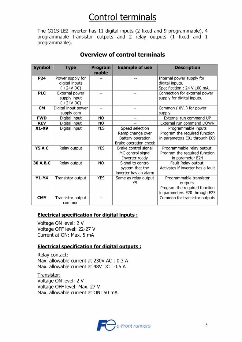
Control terminals The G11S-LE2 inverter has 11 digital inputs (2 fixed and 9 programmable), 4 programmable transistor outputs and 2 relay outputs (1 fixed and 1 programmable).
Overview of control terminals
Symbol Type Programmable
Example of use Description
P24 Power supply for digital inputs ( +24V DC)
-- -- Internal power supply for digital inputs. Specification : 24 V 100 mA.
PLC External power supply input ( +24V DC)
-- -- Connection for external power supply for digital inputs.
CM Digital input power supply com
-- -- Common ( 0V. ) for power supply
FWD Digital input NO -- External run command UP REV Digital input NO -- External run command DOWN
X1-X9 Digital input YES Speed selection Ramp change over Battery operation
Brake operation check
Programmable inputs Program the required function in parameters E01 through E09
Y5 A,C Relay output YES Brake control signal MC control signal
Inverter ready
Programmable relay output. Program the required function
in parameter E24 30 A,B,C Relay output NO Signal to control
system that the inverter has an alarm
Fault Relay output. Activates if inverter has a fault
Y1-Y4 Transistor output YES Same as relay output Y5
Programmable transistor outputs.
Program the required function in parameters E20 through E23
CMY Transistor output common
-- Common for transistor outputs
Electrical specification for digital inputs :
Voltage ON level: 2 V Voltage OFF level: 22-27 V Current at ON: Max. 5 mA Electrical specification for digital outputs :
Relay contact: Max. allowable current at 230V AC : 0.3 A Max. allowable current at 48V DC : 0.5 A
Transistor: Voltage ON level: 2 V Voltage OFF level: Max. 27 V Max. allowable current at ON: 50 mA.
6
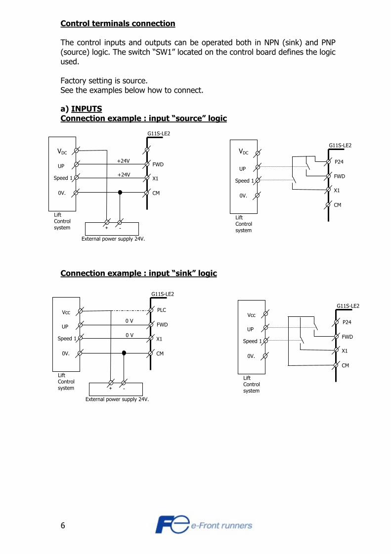
Control terminals connection The control inputs and outputs can be operated both in NPN (sink) and PNP (source) logic. The switch “SW1” located on the control board defines the logic used. Factory setting is source. See the examples below how to connect. a) INPUTS Connection example : input “source” logic
Connection example : input “sink” logic
FWD
X1
CM
External power supply 24V.
Lift Control system
UP
Speed 1
0V.
+ -
G11S-LE2
+24V
+24V FWD
X1
CM
Lift Controlsystem
UP
Speed 1
0V.
G11S-LE2
P24
FWD
X1
CM
External power supply 24V.
Lift Control system
UP
Speed 1
0V.
Vcc
+ -
G11S-LE2
0 V
0 V
PLC
FWD
X1
CM
Lift Controlsystem
UP
Speed 1
0V.
Vcc
G11S-LE2
P24
VDC VDC
7
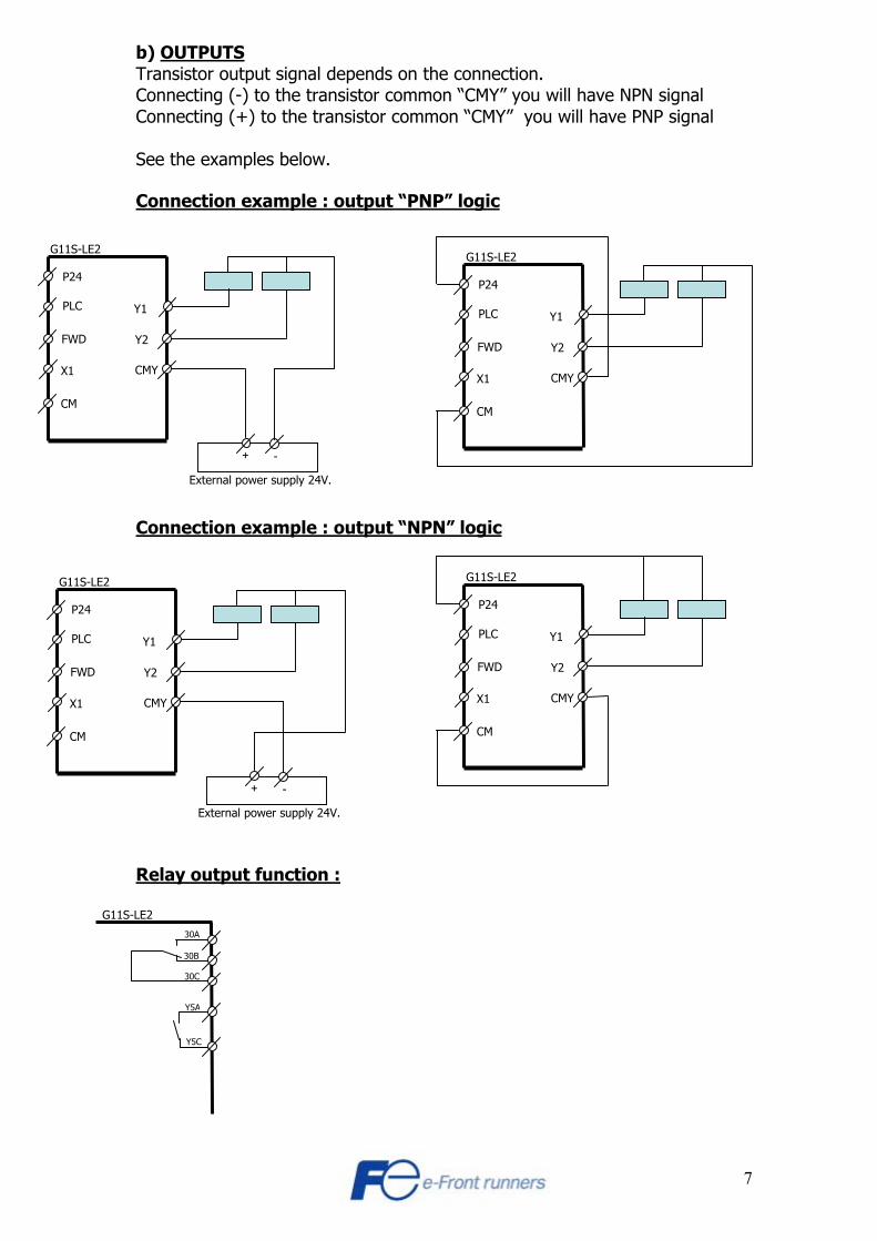
b) OUTPUTS Transistor output signal depends on the connection. Connecting (-) to the transistor common “CMY” you will have NPN signal Connecting (+) to the transistor common “CMY” you will have PNP signal See the examples below. Connection example : output “PNP” logic Connection example : output “NPN” logic Relay output function :
External power supply 24V.
+ -
FWD
X1
CM
G11S-LE2
PLC
P24
Y1
Y2
CMY
FWD
X1
CM
G11S-LE2
PLC
P24
Y1
Y2
CMY
External power supply 24V.
+ -
FWD
X1
CM
G11S-LE2
PLC
P24
Y1
Y2
CMY
FWD
X1
CM
G11S-LE2
PLC
P24
Y1
Y2
CMY
G11S-LE2
Y5A
Y5C
30A
30B
30C

8
Connection example (To select the correct resistor refer to Section 5)
Power supply3 * 400 V.
P(+) DB N(-)
P(+)
N(-)P(+)
DB 1
2
Braking chopper BU3-220-4EN
Braking resistor
Braking resistor
To P24
To an input (X)programmed as“THR” (function 9)
For inverters up to 7,5 kWFor choosing the right resistorrefer to section 5
For inverters over 7,5 kWFor choosing the right resistor refer to section 5
RFI filter
L1/R
L2/S
L3/TL3 L3’
L2 L2’
L1 L1’
Main Circuit
Control Circuit
FRENIC 5000 G11S-4LE_Ext. Power supply
+ 24 V. DC
0 V. DC
Lift control system
CM
X9
X8
X7
X6
X5
X4
X3
REV
X1
X2
PLC
FWD
P24
Vcc
UP
Down
High
Creep
Maintanence
0 V.DC
SW1
Source Sink
Y1
Y2
Y3
Y4
CMYcommen
Transistor outputsBi directional
U
V
W
Relay outputY5C
Y5A
30C
30B
30A
Alarm relay
Motor
To lift control systemGives signal if inverteris in fault mode
Relay for externalbrake control (BRK)See note.
Relay for magnetic contactors MC1 and MC2See note
MC1 MC2
Cable shield
Note : Part of a safety circuit.Refer to diagram for elevator for details
110 Vac.
0 Vac.
BRK
Power supply3 * 400 V.
P(+) DB N(-)
P(+)
N(-)P(+)
DB 1
2
Braking chopper BU3-220-4EN
Braking resistor
Braking resistor
To P24
To an input (X)programmed as“THR” (function 9)
For inverters up to 7,5 kWFor choosing the right resistorrefer to section 5
For inverters over 7,5 kWFor choosing the right resistor refer to section 5
RFI filter
L1/R
L2/S
L3/TL3 L3’
L2 L2’
L1 L1’
Main Circuit
Control Circuit
FRENIC 5000 G11S-4LE_Ext. Power supply
+ 24 V. DC
0 V. DC
Lift control system
CM
X9
X8
X7
X6
X5
X4
X3
REV
X1
X2
PLC
FWD
P24
Vcc
UP
Down
High
Creep
Maintanence
0 V.DC
SW1
Source Sink
SW1
Source Sink
Y1
Y2
Y3
Y4
CMYcommen
Transistor outputsBi directional
U
V
W
Relay outputY5C
Y5A
30C
30B
30A
Alarm relay
Motor
To lift control systemGives signal if inverteris in fault mode
Relay for externalbrake control (BRK)See note.
Relay for magnetic contactors MC1 and MC2See note
MC1 MC2
Cable shield
Note : Part of a safety circuit.Refer to diagram for elevator for details
110 Vac.
0 Vac.
BRK
9
Use of the control panel To program the inverter and to control it manually, the control panel can be used. Here is given a short example how to change parameter values (in program mode) 1) push the PRG button so the menu screen appears. 2) push the up/down arrow to menu 1 (Data Set) or 2 ( Data Check ) 3) push the FUNC/DATA button to enter to the parameter list 4) Push down or up arrow until the parameter you want to modify is highlighted
TIP: To jump between parameter blocks push the SHIFT and arrow button at the same time. 5) push the FUNC/DATA button to enter into the parameter 6) Use the SHIFT button to step to the next digit (for every push it steps one position to the right) 7) Use the up or down arrow to change the value. 8) Push the FUNC/DATA button to save and exit this parameter. If more parameters have to be programmed repeat step 4 to 8 9) Push the PRG button to return to the operating display To control the inverter from the control panel (local mode) refer to the boxes below Use the FWD or REV button to start the inverter in forward or reverse direction and STOP to stop operation Use the ARROW keys to increase or decrease the speed. Use the FUNC/DATA button to select the LED display function. Frequency, amps, line speed etc.
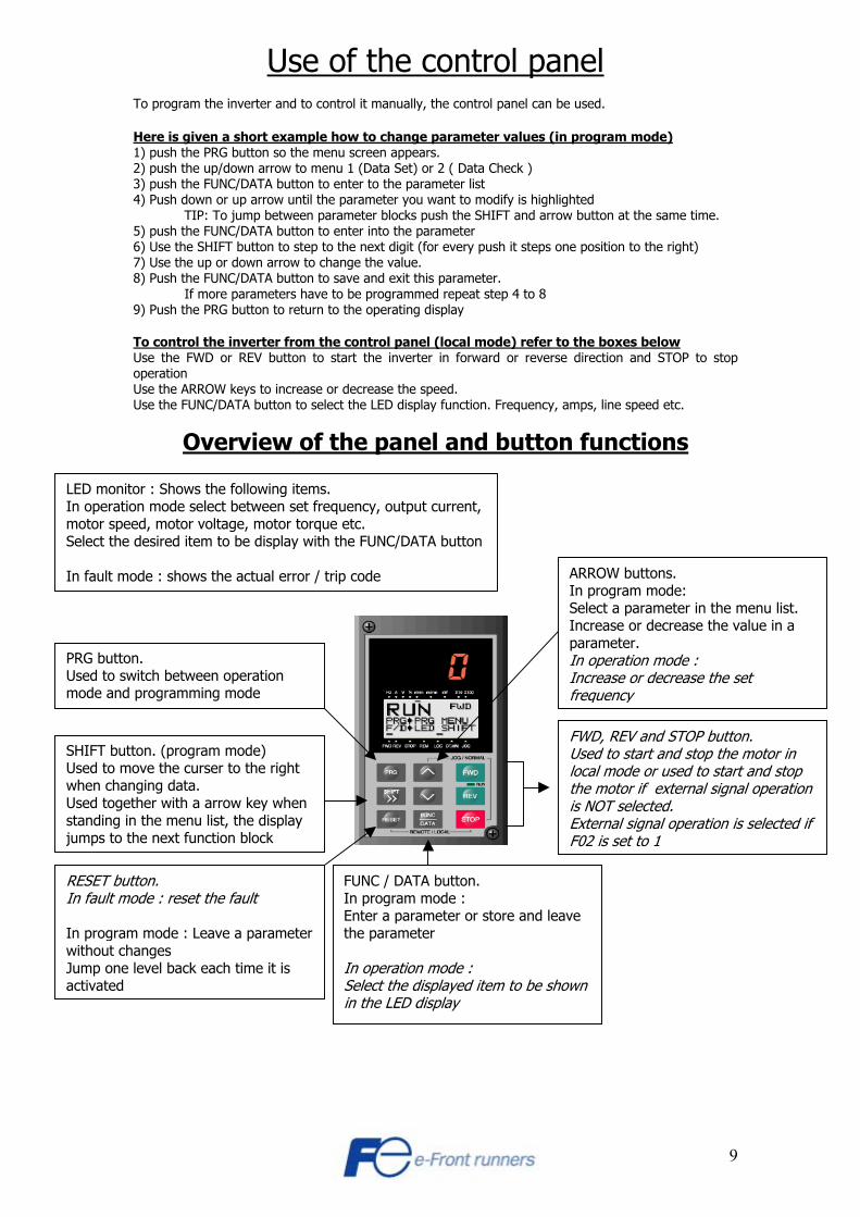
Overview of the panel and button functions
LED monitor : Shows the following items. In operation mode select between set frequency, output current, motor speed, motor voltage, motor torque etc. Select the desired item to be display with the FUNC/DATA button In fault mode : shows the actual error / trip code
PRG button. Used to switch between operation mode and programming mode
SHIFT button. (program mode) Used to move the curser to the right when changing data. Used together with a arrow key when standing in the menu list, the display jumps to the next function block
RESET button. In fault mode : reset the fault In program mode : Leave a parameter without changes Jump one level back each time it is activated
FUNC / DATA button. In program mode : Enter a parameter or store and leave the parameter In operation mode : Select the displayed item to be shown in the LED display
FWD, REV and STOP button. Used to start and stop the motor in local mode or used to start and stop the motor if external signal operation is NOT selected. External signal operation is selected if F02 is set to 1
ARROW buttons. In program mode: Select a parameter in the menu list. Increase or decrease the value in a parameter. In operation mode : Increase or decrease the set frequency

10
Use of the control panel (continuation) Menu 1. Data set. In this menu it is possible to set the parameters. Main programming menu. Menu 2. Data check.
In this menu it is possible to see the parameters and their values when scrolling through them and easily see which parameters have been changed from their default settings. If changed they will appear with a star (asterisk) beside them. Setting parameters is also possible in this mode.
Menu 3. OPR MNTR In this menu it is possible to display various operation data like output frequency, current, voltage and torque, PID values, operation status etc.
Menu 4. I/O check
In this menu you can check the inputs and outputs of the inverter (digital, analog and encoder ) This is useful when checking if the inverter is receiving the signals correctly or if it is activating the control outputs correctly
Menu 5. MAINTENANC
In this menu it is possible to check total operation time for cooling fan and power board capacitor, ROM version etc.
Menu 6. LOAD FCTR
In this menu it is possible to set a time in which the max current, average current and average breaking power will be logged
Set the time in the field “T” and start measuring with the FUNC/DATA button Menu 7. ALM INF
In this menu it is possible to see the latest alarm and various data when this alarm occurred: It is possible to see I/O status, motor output data and operating time, etc.
Menu 8. ALM CAUSE
In this menu it is possible to see the alarm history and also to display troubleshooting for the alarm selected. When an error is selected and the button FUNC/DATA is pushed the troubleshooting information appears.
Menu 9. DATA COPY
There are 3 different screens in this menu: READ, WRITE and VERIFY. Use the arrow keys to select the screen with the function desired. Start the operation by pushing FUNC/DATA key. The READ function reads data from the inverter and saves them into the control panel. The WRITE function writes into the inverter the data previously stored in the control panel. The VERIFY function compares the data stored in the panel with the actual ones of the inverter. Note: It is possible to READ, WRITE or VERIFY only among same capacity and voltage inverters (E.g. it’s not possible to READ data from a 5.5 KW inverter and to use that control panel for COPYing that stored data into a 7.5 KW inverter).

11
Differences between LE1 & LE2
Function Meaning G11S-LE1 G11S-LE2 NEW/MODIFIED Comments F03 Max. Frequency 1 50 to 120Hz 10 to 120Hz Modified Decrement of the Max. Frequency F13 E. T. Overload Relay (B. Resistor) 0 to 2 Not Available Modified Erased function F31 FMA Function 0 to 12 0 to 14 New Feedback Pulses/Torque Current
E01 to E09 X Function 0 to 38 0 to 41 New SRS new table functions C01 Operation Command (Hold Timer) Not Available 0.00 to 5.00s New FWD or REV Holding Timer C02 Deceleration Time (Stopping) Not Available 0.00 to 3600s New New ramp when RUN=0FF C03 Short Foor Operation Freq. Not Available 0.0 to 120.0Hz New Short floor function C04 Short Foor Operation Time Not Available 0.00 to 10.00s New Short floor function C13 Elevator (Speed) Not Available 1 to 500 m/min New Starting Torque Compensation C14 Elevator (Counterweight) Not Available 0 to 65535 Kg New Starting Torque Compensation C15 Elevator (Motor & Machine Inertia) Not Available 0.00 to 500 Kgm2 New Starting Torque Compensation C16 Elevator (Inertia Gain) Not Available 0 to 1000 % New Starting Torque Compensation C17 Elevator (Roping Select) Not Available 0 to 2 New Starting Torque Compensation C18 Elevator (Gear Ratio 1) Not Available 1 to 100 New Starting Torque Compensation C19 Elevator (Gear Ratio 2) Not Available 1 to 100 New Starting Torque Compensation
C21 to C28 Accel/Deceleration Times for SRS Not Available 0.01 to 3600s New Ramps for new speeds table H04/H05 Auto-Reset (New Functions) Not Available 0 to 10 times/2 to 20s Modified OC, OV, OH, dBH, OL1, OLU, LU
H06 Fan Stop Time 0 to 1 30 to 600s Modified Timer for fan stop H12 Instantaneous OC Limiting 0 to 1 0x00 to 0x12 Modified New function for current limit
A01 to A18 Alternative Motor Parameters XXXXXXXXXXXXXXX Not Available Modified Not used o28 ASR P Gain (Zero Speed) Not Available 0.01 to 200.00 New Speed Loop Gain o29 ASR I Gain (Zero Speed) Not Available 0.000 to 5.000s New Speed Loop Gain o30 ASR P Gain (Low Speed) Not Available 0.01 to 200.00 New Speed Loop Gain o31 ASR I Gain (Low Speed) Not Available 0.000 to 5.000s New Speed Loop Gain o32 ASR Switching Frequency (Low) Not Available 0 to 120Hz New Transition in ASR o33 ASR Switching Frequency (High) Not Available 0 to 120Hz New Transition in ASR o53 Starting Torque Comp. (Select) Not Available 0 to 1 New Starting Torque Compensation o54 S.T.C. (Calculation Start Pulse 1) Not Available 0 to 255 New Starting Torque Compensation o55 S.T.C. (Calculation Start Pulse 2) Not Available 0 to 255 New Starting Torque Compensation o56 S.T.C. (Pulse Count) Not Available 0 to 255 New Starting Torque Compensation

12
Parameter setting example Here is a parameter list for typical functions when adjusting an elevation application. Note: Please, the parameters described below, are just an example. The parameter setting could be change according the application.
Function Open loop Value
Closed loop Value
Comment Page
F00 1 1 Data protection 14 F01 2 2 Frequency command 14 F02 1 1 Operation method 14 F03 50 50 Maximum frequency 14 F04 50 50 Base frequency 14 F05 400 400 Rated voltage (at base frequency) 14 F07 2.5 2.5 Acceleration time 14 F08 1.8 1.8 Deceleration time 14 F09 0 0 Torque boost 14 F20 0.5 0 DC brake (Starting frequency) 14 F21 80 0 DC brake (Braking level) 14 F22 1 0 DC brake (Braking time) 15 F23 0.5 0 Starting frequency 15 F24 0.5 1 Starting frequency (Holding time) 15 F25 0.5 0.1 Stop frequency 15 F26 10 10 Motor sound (carrier frequency) 15 F42 1 1 Torque vector control 15 E01 0 0 X1 terminal function (multi speed SS1) Digital input 15,23-25 E02 1 1 X2 terminal function (multi speed SS2) Digital input 15,23-25 E03 2 2 X3 terminal function (multi speed SS4) Digital input 15,23-25 E20 36 36 Y1 terminal function (contactor control, CTL) Transistor output 15 E24 35 35 Y5 A, Y5 C terminal function (brake control, BRKS) Relay output 15 E46 1 1 LCD monitor (language) 16 C01 0 0 Operation command (FWD/REV) holding timer 16 C02 0 0 Deceleration time (stopping) 16 C03 0 0 Short floor operation (Frequency) 17 C04 0 0 Short floor operation (Time) 17 C05 50 50 Multi speed SS1 (high speed) 17 C06 25 25 Multi speed SS2 (inspection speed) 17 C09 5 2 Multi speed SS4 (creep speed) 17 C13 -- application data Elevator speed (parameter for Starting torque compensation) 17,45,46 C14 -- application data Caunter weight (parameter for Starting torque compensation) 17,45,46 C15 -- application data Motor and machine inertia (for Starting torque ompensation) 17,45,46 C16 -- application data Inertia gain (parameter for Starting torque compensation) 17,45,46 C17 -- application data Roping select (parameter for Starting torque compensation) 18,45,46 C18 -- application data Gear ratio 1 (parameter for Starting torque compensation) 18,45,46 C19 -- application data Gear ratio 2 (parameter for Starting torque compensation) 18,45,46 P01 motor data motor data Number of motor poles 18,41,42 P02 motor data motor data Motor capacity (Kw) 18,41,42 P03 motor data motor data Motor rated current 18,41,42 P06 motor data motor data Motor no-load current 18,41,42 P09 motor data motor data Motor slip compensation driving control (look also o43) 18,41,42 H04 1 1 Auto-reset (times) 18 H05 5 5 Auto-reset (reset interval time) 18 H06 999 999 Fan stop time 18 H07 2 2 S-curve function 18,24 H12 00 00 Current limit and short-circuit detection function 19 H18 0 0 Torque control (torque bias function) 19,40
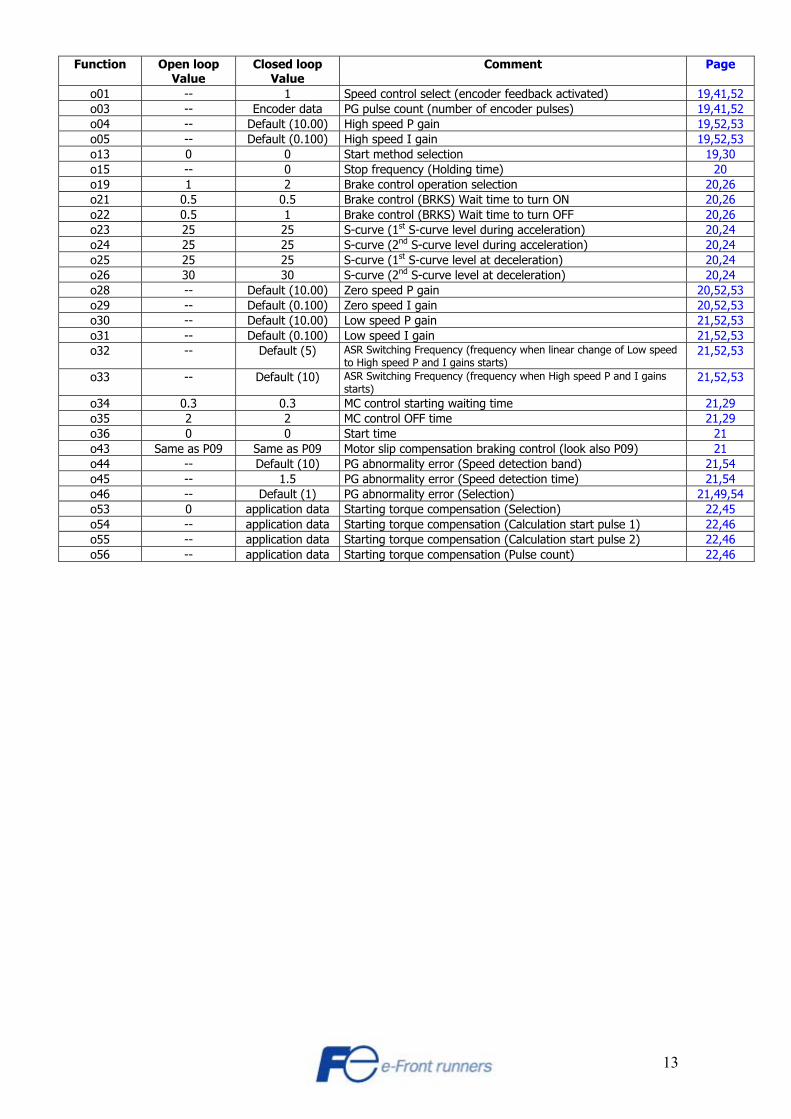
13
Function Open loop Value
Closed loop Value
Comment Page
o01 -- 1 Speed control select (encoder feedback activated) 19,41,52 o03 -- Encoder data PG pulse count (number of encoder pulses) 19,41,52 o04 -- Default (10.00) High speed P gain 19,52,53 o05 -- Default (0.100) High speed I gain 19,52,53 o13 0 0 Start method selection 19,30 o15 -- 0 Stop frequency (Holding time) 20 o19 1 2 Brake control operation selection 20,26 o21 0.5 0.5 Brake control (BRKS) Wait time to turn ON 20,26 o22 0.5 1 Brake control (BRKS) Wait time to turn OFF 20,26 o23 25 25 S-curve (1st S-curve level during acceleration) 20,24 o24 25 25 S-curve (2nd S-curve level during acceleration) 20,24 o25 25 25 S-curve (1st S-curve level at deceleration) 20,24 o26 30 30 S-curve (2nd S-curve level at deceleration) 20,24 o28 -- Default (10.00) Zero speed P gain 20,52,53 o29 -- Default (0.100) Zero speed I gain 20,52,53 o30 -- Default (10.00) Low speed P gain 21,52,53 o31 -- Default (0.100) Low speed I gain 21,52,53 o32 -- Default (5) ASR Switching Frequency (frequency when linear change of Low speed
to High speed P and I gains starts) 21,52,53
o33 -- Default (10) ASR Switching Frequency (frequency when High speed P and I gains starts)
21,52,53
o34 0.3 0.3 MC control starting waiting time 21,29 o35 2 2 MC control OFF time 21,29 o36 0 0 Start time 21 o43 Same as P09 Same as P09 Motor slip compensation braking control (look also P09) 21 o44 -- Default (10) PG abnormality error (Speed detection band) 21,54 o45 -- 1.5 PG abnormality error (Speed detection time) 21,54 o46 -- Default (1) PG abnormality error (Selection) 21,49,54 o53 0 application data Starting torque compensation (Selection) 22,45 o54 -- application data Starting torque compensation (Calculation start pulse 1) 22,46 o55 -- application data Starting torque compensation (Calculation start pulse 2) 22,46 o56 -- application data Starting torque compensation (Pulse count) 22,46

14
Parameter explanation Following there is an explanation of the normally used parameters and setting examples. F00 = 1 DATA PROTECTION 0 = no protection 1 = protection With this parameter it is possible to lock the parameters so they can’t be changed from the panel. Press the STOP and while holding this also press the ARROW key to change the setting. F01 = 2 FREQUENCY COMMAND Frequency reference from the digital inputs (X1 through X9) F02 = 1 OPERATION METHOD
0 = Local control (operator panel) 1 = External RUN signals (FWD = up and REV = down)
F03 = 50 Hz MAXIMUM FREQUENCY This function sets the maximum output frequency. F04 = 50 Hz BASE FREQUENCY This function sets the maximum output frequency in the constant torque range, or the output frequency at the rated output voltage. F05 = 400 V RATED VOLTAGE (at base frequency) This function sets the rated value of the voltage output. F07 = 2.5 sec. ACCELERATION TIME Sets the acceleration time for the output frequency from startup to maximum frequency (F03) F08 = 1.8 sec. DECELERATION TIME Sets the deceleration time for the output frequency from maximum frequency (F03) to operation stop. F09 = 0 TORQUE BOOST This parameter is for V/f mode. Try from 5 to 20 depending on the application. Note: Large torque boost value might cause motor overheating. When using torque vector control mode ([F42=1]), set this parameter to 0. F20 : DC BRAKE (STARTING FREQUENCY)
Open loop = 0.5 Hz closed loop = 0 Hz (not used) Defines at which frequency the DC brake has to activate. DC brake is used to stop and hold the motor before closing the brake F21 : DC BRAKE (BRAKE LEVEL) (injection level in %)
Open loop = 80% closed loop = 0 (not used) Defines the braking level. The higher setting the more holding torque will be applied to the motor. Note: Large DC brake level value could cause motor to overheating.

15
F22 : DC BRAKE (BRAKING TIME)
Open loop = 0.5 sec Closed loop = 0.0 (inactive) Defines the DC brake time. Set so the mechanical brake has time to close within this time. F23 : STARTING FREQUENCY
Open loop = 0.5 Hz Closed loop = 0.0 Hz (*) Starting frequency. Hold the motor while the brake is being released. A small value may not avoid roll back, and a high value may produce a shock. F24 : STARTING FREQUENCY (HOLDING TIME)
Open loop = 0.5 sec. Closed loop = 1 sec. (*) Holding time of the starting frequency. During this period the brake should be released. F25 : STOP FREQUENCY
Open loop = 0.5 Hz Closed loop = 0.1 Hz (*) Stop frequency is related to BRKS (brake control signal). Note: The operation does not start when starting freq. [F23] is < than stop freq. [F25]. (*) Depends on controller signals. See “timing chart (closed loop)” in section 2 for more details. F26 = 10 KHz MOTOR SOUND (CARRIER FREQUENCY) This parameter sets the carrier frequency to the motor. The higher the setting the less acoustic noise from the motor. Setting possible : 0.75 to 15 kHz. (set normally to 10) F42 = 1 TORQUE VECTOR CONTROL 0 = V/f mode
1 = Activation of the torque vector control. See “auto tuning” in section 3.
E01 = 0 MULTI SPEED SS1 Setup of the first digital input as multi speed selection 1 (SS1) E02 = 1 MULTI SPEED SS2 Setup of the first digital input as multi speed selection 2 (SS2) E03 = 2 MULTI SPEED SS4 Setup of the first digital input as multi speed selection 3 (SS4) For a detailed description of the multi speed function see under section 2 “Run and speed settings” E20 = 36 CONTACTOR CONTROL Setup of transistor output Y1 as contactor control signal (CTL) Alternatively set the function “AX”(code 15) to control the contactors. In this case the signal will be on as long as the inverter is in RUN mode. For a detailed description of the contactor control see under section 2 “Contactor control” E24 = 35 BRAKE CONTROL Setup of relay output Y5 as brake control signal (BRKS) For a detailed description of the brake control see under section 2 “Brake control”
16
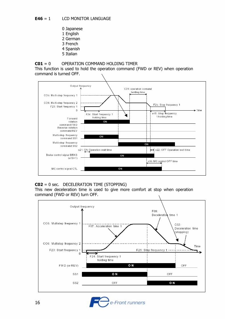
E46 = 1 LCD MONITOR LANGUAGE 0 Japanese 1 English 2 German 3 French 4 Spanish 5 Italian
C01 = 0 OPERATION COMMAND HOLDING TIMER This function is used to hold the operation command (FWD or REV) when operation command is turned OFF. C02 = 0 sec. DECELERATION TIME (STOPPING) This new deceleration time is used to give more comfort at stop when operation command (FWD or REV) turn OFF.

17
C03 = 0 Hz SHORT FLOOR OPERATION (FREQUENCY) This parameter establishes the frequency limit to do effective the short floor function. C04 = 0 sec. SHORT FLOOR OPERATION (TIME) When short floor function starts, this parameter sets the duration. C06 = 50 Hz HIGH SPEED FREQUENCY (when input X1 is activated) C07 = 25 Hz INSPECTION SPEED FREQUENCY (when input X2 is activated) C08 : CREEP SPEED FREQUENCY (when X1 and X3 are activated)
Open loop = 5 Hz Closed loop = 2 Hz For a detailed description of the multi speed function see under section 2 “Run and speed settings” C13 = -- ELEVATOR SPEED (STARTING TORQUE COMPENSATION) For a detailed description of the Starting torque compensation see under section 3 “Starting torque compensation function” C14 = -- COUNTER WEIGHT (STARTING TORQUE COMPENSATION) For a detailed description of the Starting torque compensation see under section 3 “Starting torque compensation function” C15 = -- MOTOR AND MACHINE INERTIA (STARTING TORQUE COMPENSATION) For a detailed description of the Starting torque compensation see under section 3 “Starting torque compensation function” C16 = -- INERTIA GAIN (STARTING TORQUE COMPENSATION) For a detailed description of the Starting torque compensation see under section 3 “Starting torque compensation function”

18
C17 = -- ROPING SELECT (STARTING TORQUE COMPENSATION) For a detailed description of the Starting torque compensation see under section 3 “Starting torque compensation function” C18 = -- GEAR RATIO 1 (STARTING TORQUE COMPENSATION) For a detailed description of the Starting torque compensation see under section 3 “Starting torque compensation function” C19 = -- GEAR RATIO 2 (STARTING TORQUE COMPENSATION) For a detailed description of the Starting torque compensation see under section 3 “Starting torque compensation function” P01 = -- NUMBER OF MOTOR POLES P02 = -- MOTOR CAPACITY P03 = -- MOTOR RATED CURRENT P06 = -- MOTOR NO-LOAD CURRENT (Do not leave this parameter to 0 value) P09 = -- MOTOR SLIP COMPENSATION DRIVING CONTROL For more information look under section 3 “auto tuning” H04 = 1 AUTO RESET (TIMES) If it is wanted that the inverter try to reset an error occurred set the number of tries in this parameter. Choose between 0 and 10 tries. H05 = 5 sec. AUTO RESET (RESET INTERVAL TIME) In this parameter set the interval between each auto reset. When resetting an error and it reoccurs then the inverter tries again after the time set in this parameter. H06 = 999 sec. FAN STOP TIME This parameter selects the method in which the inverter cooling fan operates. 999 = Fan runs always 30 sec. to 600 sec.= Fan operation depends on the heat sink
temperature and RUN signal (i.e.: if set to 300s, after RUN signal is off, and the heat sink temperature is lower of an internal set value, the fan stops in 5 minutes)
H07 = 2 S-CURVE FUNCTION 0 = no S-curve (linear ramps) 2 = Activation of S-curve With above setting value, it is possible to modify each point of the acceleration and deceleration S-curves (o23-o26)

19
H12 = 00 CURRENT LIMIT AND SHORT-CIRCUIT DETECTION FUNCTION The current limit function controls inverter output and cuts the current when above the inverter protection level. Generated motor torque may be reduced when this function is activated (set 00 for elevating applications). The short circuit detection function, could be help with the starting peak current in some motors. o01 : SPEED CONTROL SELECT
closed loop = 1 Activation of encoder feedback, (closed loop operation) Look under section 5 “encoder option board” for more information. o03 : NUMBER OF ENCODER PULSES
closed loop = Check encoder pulses (1024,2048,4096...) Number of encoder feedback pulses. Look under section 5 “encoder option board” for more information. o04 : SPEED LOOP P-GAIN (at High speed)
closed loop = 10 (default) ASR - P gain at High speed. Look under section 5 “encoder option board” for more information. o05 : SPEED LOOP I-GAIN (at High speed)
closed loop = 0.100 (default) ASR - I gain at High speed. Look under section 5 “encoder option board” for more information. o13 : START METHOD SELECTION Look under section 2 “Start method selection function” for more information.
20
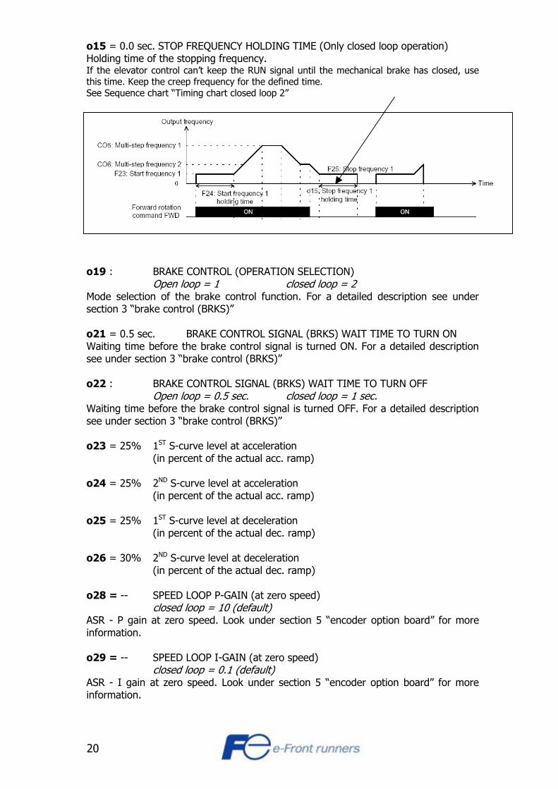
o15 = 0.0 sec. STOP FREQUENCY HOLDING TIME (Only closed loop operation) Holding time of the stopping frequency. If the elevator control can’t keep the RUN signal until the mechanical brake has closed, use this time. Keep the creep frequency for the defined time. See Sequence chart “Timing chart closed loop 2” o19 : BRAKE CONTROL (OPERATION SELECTION)
Open loop = 1 closed loop = 2 Mode selection of the brake control function. For a detailed description see under section 3 “brake control (BRKS)” o21 = 0.5 sec. BRAKE CONTROL SIGNAL (BRKS) WAIT TIME TO TURN ON Waiting time before the brake control signal is turned ON. For a detailed description see under section 3 “brake control (BRKS)” o22 : BRAKE CONTROL SIGNAL (BRKS) WAIT TIME TO TURN OFF
Open loop = 0.5 sec. closed loop = 1 sec. Waiting time before the brake control signal is turned OFF. For a detailed description see under section 3 “brake control (BRKS)” o23 = 25% 1ST S-curve level at acceleration (in percent of the actual acc. ramp) o24 = 25% 2ND S-curve level at acceleration (in percent of the actual acc. ramp) o25 = 25% 1ST S-curve level at deceleration (in percent of the actual dec. ramp) o26 = 30% 2ND S-curve level at deceleration (in percent of the actual dec. ramp) o28 = -- SPEED LOOP P-GAIN (at zero speed)
closed loop = 10 (default) ASR - P gain at zero speed. Look under section 5 “encoder option board” for more information. o29 = -- SPEED LOOP I-GAIN (at zero speed)
closed loop = 0.1 (default) ASR - I gain at zero speed. Look under section 5 “encoder option board” for more information.

21
o30 = -- SPEED LOOP P-GAIN (at low speed) closed loop = 10 (default)
ASR - P gain at low speed. Look under section 5 “encoder option board” for more information. o31 = -- SPEED LOOP I-GAIN (at low speed)
closed loop = 0.1 (default) ASR - I gain at low speed. Look under section 5 “encoder option board” for more information. o32 = -- ASR Switching Frequency (Low)
closed loop = 5 Hz (default) Absolut value of setting frequency. Reached this frequency, linear change of Low speed P and I gains starts to o33 time (when High speed P and I gains are activated). Look under section 5 “encoder option board” for more information. o33 = -- ASR Switching Frequency (High)
closed loop = 10 Hz (default) Absolut value of setting frequency. Reached this frequency, High speed P and I gains are activated. Look under section 5 “encoder option board” for more information. o34 = 0.3 sec. MC CONTROL ON-DELAY TIME The time defines for how long the inverter will wait before starting motor output, after start signal (RUN) is given. The objective is to assure that the contactors are completely closed before the inverter starts outputting frequency. o35 = 2 sec. MC CONTROL OFF-DELAY TIME The time defines when to open the output contactors after the stop signal is given. The objective is to assure that the inverter has no output frequency when the contactors are opened. o36 = 0 sec. START TIME This start time starts after o34 parameter value time. During START TIME the output frequency increases to reach the starting frequency (a slope is created). o43 = -- SLIP COMPENSATION CONTROL (BRAKING SIDE) Set normally as P09 value. For more information look under section 3 “auto tuning” o44 = -- PG ABNORMALITY ERROR (SPEED DETECTION BAND) closed loop = 10% (default) See section 5 “encoder option board” for more information. o45 = -- PG ABNORMALITY ERROR (SPEED DETECTION TIMER) closed loop = 1.5 sec. See section 5 “encoder option board” for more information. o46 = -- PG ABNORMALITY ERROR (SELECTION)
closed loop = 1 (default) See section 5 “encoder option board” for more information.

22
o53 = -- STARTING TORQUE COMPENSATION (Select) NOTE: Only Closed loop !!! Setting this parameter to 1 the Starting torque compensation becomes effective. For a detailed description of the Starting torque compensation see under section 3 “Starting torque compensation function” o54 = -- STARTING TORQUE COMPENSATION (Calculation start pulse 1) For a detailed description of the Starting torque compensation see under section 3 “Starting torque compensation function” o55 = -- STARTING TORQUE COMPENSATION (Calculation start pulse 2) For a detailed description of the Starting torque compensation see under section 3 “Starting torque compensation function” o56 = -- STARTING TORQUE COMPENSATION (Pulse count) For a detailed description of the Starting torque compensation see under section 3 “Starting torque compensation function”

23
SECTION 2
Run and speed settings The RUN command The up and down command (RUN) to the inverter normally comes from a remote signal for elevator applications. Default for the inverter is local (control panel) so therefore a change in parameter F02 has to be made. Setting parameter F02= 1 will result in run command from the terminals FWD and REV placed in the control board of the inverter. The SPEED command The speed selection in elevator applications is normally done via digital inputs. Setting the parameter F01= 2, speed command will come from digital inputs (SS1, SS2, SS4). SS1 to SS4 can be assigned to any of the digital inputs (X1 to X9). Following the “parameter setting example”, high speed, creep speed and maintenance speed are selected through a combination of the inputs X1, X2 and X3. E01 is the parameter for selecting the function of the input X1. Set E01=0 for selecting input X1 as SS1 (Speed Selecting 1). X2 function is selected with the parameter E02. Program E02=1 for selecting input X2 as SS2. X3 function is selected with the parameter E03. Program E03=2 for selecting input X3 as SS4. In the speed selection table 1 you can see that: When X1(SS1) is activated high speed (C05) is selected. When X2 (SS2) is activated inspection speed (C06) is selected. When X1(SS1) and X3 (SS2) are activated, creep speed (C09) is selected. Speed selection table 1
Digital inputs X3
SS4 (code 2) X2
SS2 (code 1) X1
SS1 (code 0)
Frequency selected
ON C05 ON C06 ON ON C07
ON C08 ON ON C09 ON ON C10 ON ON ON C11

24
Acceleration/Deceleration ramps and S-curves Acceleration/Deceleration ramps The inverter has 4 pairs of acceleration and deceleration ramps. Pair no.1 (F07 and F08) is the default one and is active if no other is chosen. To choose another pair of ramps, 1 or 2 digital inputs have to be assigned as “acceleration/deceleration selection”. When parameters E01 to E09 are assigned to code 4 or 5. X1 to X9 function is selected with the parameter E01 to E09. In the following example, input X4 and X5 have been chosen as inputs for acc./dec. ramp selection. Program E04=4 for selecting input X4 as “acceleration/deceleration selection 1”. Program E05=5 for selecting input X5 as “acceleration/deceleration selection 2”. Program desired acceleration and deceleration ramps in parameters E10 to E15. Acc/Dec. setting range is : 0.01 to 3600 s. Acc. 1 ( F07 )
Dec. 1 ( F08 ) Acc. 2 ( E10 ) Dec. 2 ( E11 )
Acc. 3 ( E12 ) Dec. 3 ( E13 )
Acc. 4 ( E14 ) Dec. 4 ( E15 )
Input 4 ( X4 ) ON ON Input 5 ( X5 ) ON ON S-curves To select the S-curve function set H07 = 2 There are 4 ‘jerk’ points in total: 2 jerk points for the acceleration and 2 for the deceleration. Jerk points are determined in % (of the total acceleration or deceleration ramp) Maximum value for the jerk points is 50 % Look at the graph below for reference. It is possible to have linear curve at stop. In this case set parameter o27=1 Please, note that S-curve pattern takes longer time than linear curve. In case linear curve is selected, stopping distance is smaller (leveling distance s smaller) but less comfort is experienced in the car during acceleration and deceleration.
S-curve o24
S-curveo25
S-curveo26
S-curve o23
S-curve o25
S-curveo26

25
Speed and Acceleration/Deceleration time selection New multi speed selection table with the LE2: It is possible to save two digital inputs if next table is used. Now, each speed selected has a associated ramps (acceleration and deceleration). Speed command will come from digital inputs (SRS1, SRS2, SRS4). SRS1 to SRS4 can be assigned to any of the digital inputs (X1 to X9). E01 is the parameter for selecting the function of the input X1. Set E01=39 for selecting input X1 as SRS1 (Speed Selecting 1). X2 function is selected with the parameter E02. Program E02=40 for selecting input X2 as SRS2. X3 function is selected with the parameter E03. Program E03=41 for selecting input X3 as SRS4. In the speed selection table 2 you can see that: When NO digital input is active, speed (C05) is selected with F07 & F08 as a ramps. When only X1(SRS1) is active, speed (C06) is selected with E10 & E11 as a ramps. When only X2 (SRS2) is active, speed (C07) is selected with E12 & E13 as a ramps. When X1(SRS1) and X2 (SRS2) are activated, speed (C08) is selected with E14 & E15. Speed selection table 2
NOTE: If Speed selection table 2 (SRS1, SRS2 and SRS4) is selected, multi speed selection (SS1, SS2 and SS4) and Acceleration/Deceleration time selection (RT1 and RT2) becomes invalid.
Digital inputs X3
SRS4 (code 41) X2
SRS2 (code 40) X1
SRS1 (code 39)
Frequency selected
Acceleration Time
Deceleration Time
OFF OFF OFF C05 F07 F08 OFF OFF ON C06 E10 E11 OFF ON OFF C07 E12 E13 OFF ON ON C08 E14 E15 ON OFF OFF C09 C21 C22 ON OFF ON C10 C23 C24 ON ON OFF C11 C25 C26 ON ON ON C12 C27 C28
26
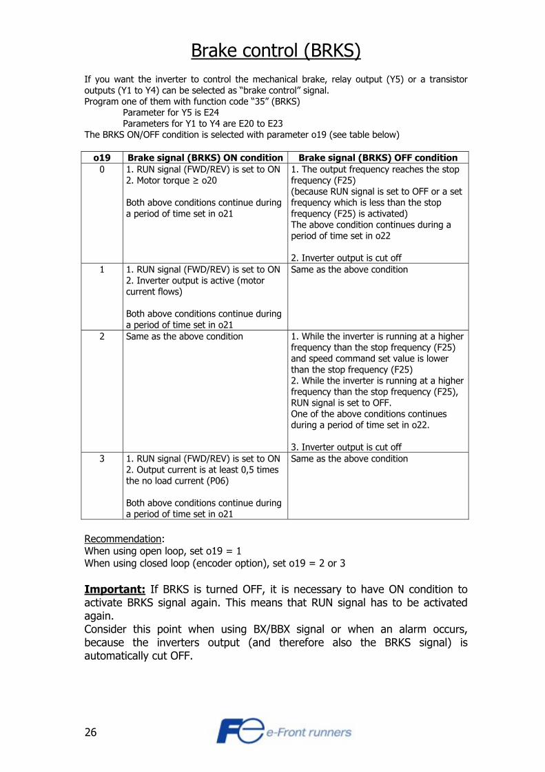
Brake control (BRKS) If you want the inverter to control the mechanical brake, relay output (Y5) or a transistor outputs (Y1 to Y4) can be selected as “brake control” signal. Program one of them with function code “35” (BRKS) Parameter for Y5 is E24 Parameters for Y1 to Y4 are E20 to E23 The BRKS ON/OFF condition is selected with parameter o19 (see table below)
o19 Brake signal (BRKS) ON condition Brake signal (BRKS) OFF condition 0 1. RUN signal (FWD/REV) is set to ON
2. Motor torque ≥ o20 Both above conditions continue during a period of time set in o21
1. The output frequency reaches the stop frequency (F25) (because RUN signal is set to OFF or a set frequency which is less than the stop frequency (F25) is activated) The above condition continues during a period of time set in o22 2. Inverter output is cut off
1 1. RUN signal (FWD/REV) is set to ON 2. Inverter output is active (motor current flows) Both above conditions continue during a period of time set in o21
Same as the above condition
2 Same as the above condition 1. While the inverter is running at a higher frequency than the stop frequency (F25) and speed command set value is lower than the stop frequency (F25) 2. While the inverter is running at a higher frequency than the stop frequency (F25), RUN signal is set to OFF. One of the above conditions continues during a period of time set in o22. 3. Inverter output is cut off
3 1. RUN signal (FWD/REV) is set to ON 2. Output current is at least 0,5 times the no load current (P06) Both above conditions continue during a period of time set in o21
Same as the above condition
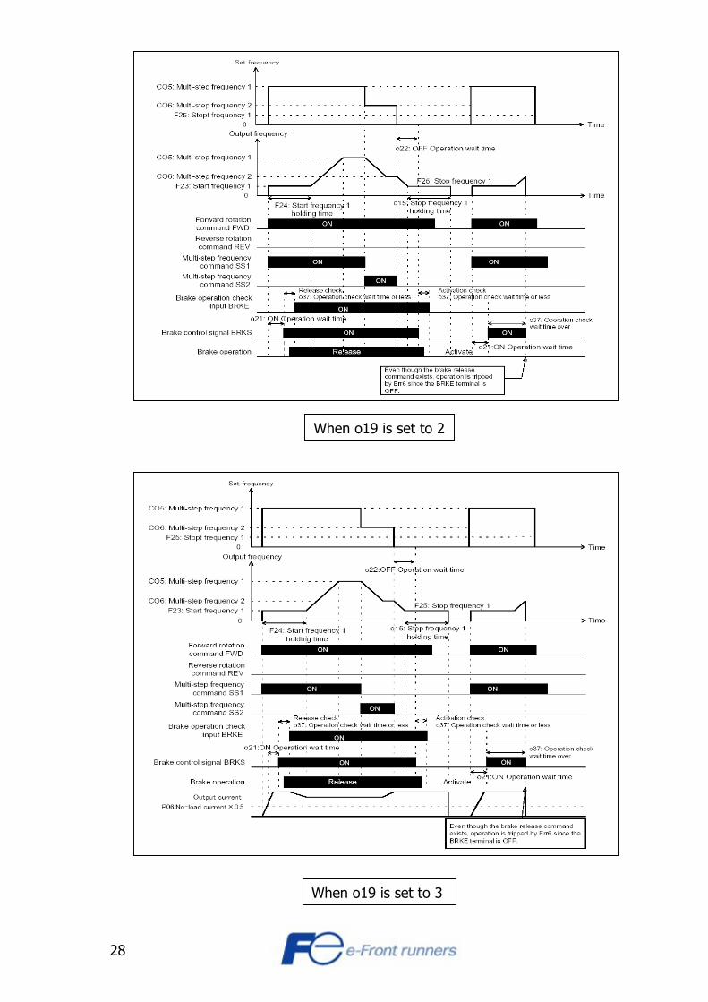
Recommendation: When using open loop, set o19 = 1 When using closed loop (encoder option), set o19 = 2 or 3 Important: If BRKS is turned OFF, it is necessary to have ON condition to activate BRKS signal again. This means that RUN signal has to be activated again. Consider this point when using BX/BBX signal or when an alarm occurs, because the inverters output (and therefore also the BRKS signal) is automatically cut OFF.

27
See operation charts for the brake control signal depending on o19 selection:
When o19 is set to 1
When o19 is set to 0
28
When o19 is set to 2
When o19 is set to 3
29
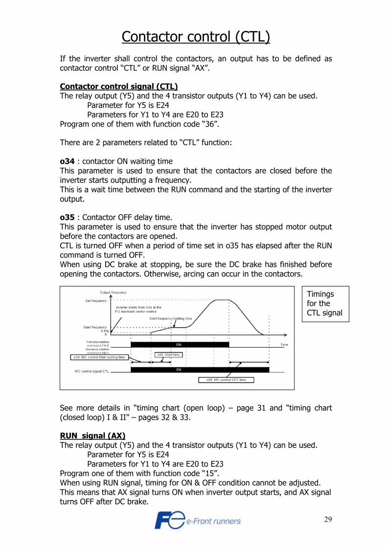
Contactor control (CTL) If the inverter shall control the contactors, an output has to be defined as contactor control “CTL” or RUN signal “AX”. Contactor control signal (CTL) The relay output (Y5) and the 4 transistor outputs (Y1 to Y4) can be used. Parameter for Y5 is E24 Parameters for Y1 to Y4 are E20 to E23 Program one of them with function code “36”. There are 2 parameters related to “CTL” function: o34 : contactor ON waiting time This parameter is used to ensure that the contactors are closed before the inverter starts outputting a frequency. This is a wait time between the RUN command and the starting of the inverter output. o35 : Contactor OFF delay time. This parameter is used to ensure that the inverter has stopped motor output before the contactors are opened. CTL is turned OFF when a period of time set in o35 has elapsed after the RUN command is turned OFF. When using DC brake at stopping, be sure the DC brake has finished before opening the contactors. Otherwise, arcing can occur in the contactors.
See more details in “timing chart (open loop) – page 31 and “timing chart (closed loop) I & II” – pages 32 & 33. RUN signal (AX) The relay output (Y5) and the 4 transistor outputs (Y1 to Y4) can be used. Parameter for Y5 is E24 Parameters for Y1 to Y4 are E20 to E23 Program one of them with function code “15”. When using RUN signal, timing for ON & OFF condition cannot be adjusted. This means that AX signal turns ON when inverter output starts, and AX signal turns OFF after DC brake.
Timings for the CTL signal

30
Start method selection function o13 : Defines if a DC brake (0 Hz) or a starting frequency (>0 Hz) is output at start.
o13 = 0 : Starting frequency (F23) is output. o13 = 1 : DC brake (0 Hz) is output. See the “specifications for FRENIC5000G11S-LE2” sheet for more details
DC brake at start is used (o13 = 1)
DC brake at start is not used (o13=0)
31
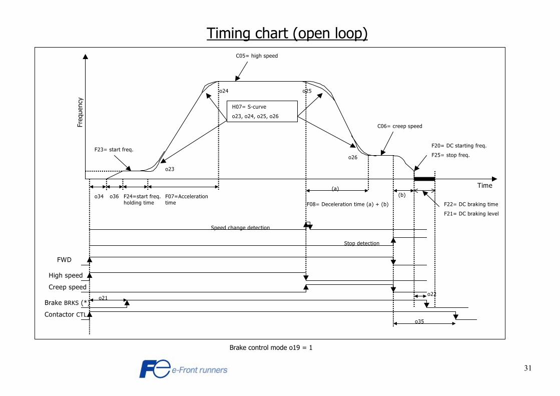
Timing chart (open loop)
Brake control mode o19 = 1
C05= high speed
C06= creep speed
F07=Acceleration time
F24=start freq. holding time
F23= start freq.
F08= Deceleration time (a) + (b)
(a)(b)
H07= S-curve
o23, o24, o25, o26
High speed
Speed change detection
Stop detection
FWD
Creep speed
F20= DC starting freq.
F25= stop freq.
F22= DC braking time
F21= DC braking level
Freq
uenc
y
Time
o36o34
o23
o24 o25
o26
Brake BRKS (*)o22
o21
Contactor CTLo35

32
Timing chart (closed loop - I) UP/DOWN (FWD/REV) is removed after 0 Speed.
C05= high speed
C06= creep speed
F07= Acceleration timeF24= start freq. holding time
F23= start freq.
F08= Deceleration time (a) + (b)
(a) (b)
H07= S-curve
o23, o24, o25, o26
High speed
Speed change detection
Stop detection
FWD
Creep speed
F25= stop freq.
Freq
uenc
y
Time
o34
o23
o24 o25
o26
Brake BRKS (*)o22o21
Contactor CTLo35
Zero speed command
(optionally)
Brake control mode o19 = 2

33
Timing chart (closed loop - II)
UP/DOWN (FWD/REV) is removed at same time as Creep speed.
C05= high speed
C06= creep speed
F07= Acceleration timeF24= start freq. holding time
F23= start freq.
F08= Deceleration time (a) + (b)
(a) (b)
H07= S-curve
o23, o24, o25, o26
High speed
Speed change detection
Stop detection
FWD
Creep speed
F25= stop freq.
Freq
uenc
y
Time
o34
o23
o24 o25
o26
Brake BRKS (*)o22o21
Contactor CTLo35
o15= stop freq. holding time
(optionally)
Brake control mode o19 = 2

34
Parameter list for the LE2 firmware
Fundamental functions

35
Parameter list for the LE2 firmware
Extension terminal functions

36
Parameter list for the LE2 firmware Control functions
Motor parameters

37
High performance functions
38
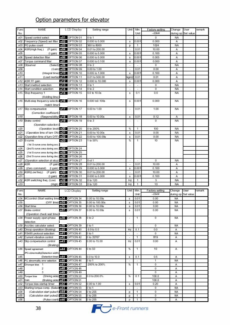
Option parameters for elevator

39
Control block diagram ( open loop )

40
Control block diagram ( closed loop )

41
SECTION 3 Auto tuning
There are 2 different types of auto tuning: Dynamic and static. Dynamic tuning is the most appropriated one, but requires the motor to be free (cabin should be decoupled). If it isn’t possible to decouple the cabin, tune the motor using the static tuning. In this case it is necessary manually to set manually the motor no load current (P06). Note: If encoder is used, it’s necessary to set these parameters before doing the auto tuning: o01: closed loop control Set the value 1 in this parameter to activate the closed loop control. o03: Number of encoder pulses Set the number of encoder pulses per revolution in this parameter. Auto tuning step by step 1) First set manually the following parameters.
F03 : Max. frequency. F04 : Base frequency. F05 : Motor rated voltage. P01 : number of motor poles (2: 3.000 rpm, 4: 1.500 rpm, 6: 1.000
rpm) P02 : Motor rated power (kW). See motor rating plate.
(After above point, the inverter assigns automatically P03, P06,P07 and P08) P03 : Motor rated current (Amps). See motor rating plate.
In case of static tuning, set manually P06 (motor no load current) - see note 1.
P09: slip compensation - see note 2 how to calculate. 2) Now choose the most appropriate type of auto tuning for the lift application.
In case of dynamic auto tuning set P04 to 2 In case of static (no rotating) auto tuning set P04 to 1
3) Now proceed with the auto tuning operation.
Push FWD or REV button on the keypad (if local mode is activated), or active the digital input FWD or REV (if remote mode is chosen)
For changing from remote mode to local mode, see chapter “Overview of the panel and button functions” in Section 1. If error “Er7” appears, it might be necessary to activate the output contactors (MC) manually.
After tuning has stopped (when 3 current pulses have been heard in the motor), press the STOP button or remove FWD or REV input.
4) F42 : Torque vector control. For activation of the torque vector control mode, set F42 to 1.

42
Should a ‘P’ parameter be required to be changed manually after auto tuning, it is will be necessary to do auto tuning again (point 3). Note 1: If the motor no-load current is unknown (P06), set the value so it is between 40 and 60 % of motor rated current (P03). Note 2: To calculate the slip of the motor (P09), motor rated speed (N) has to be known. This value is normally specified on the motor plate. The synchronous speed (Ns) is: 2 poles motor: 3000 rpm 4 poles motor: 1500 rpm 6 poles motor: 1000 rpm Then use this formula to find the slip in Hz. 50 * (Ns-N) / Ns Here an example of a 2 pole motor with a rated speed of 2850 rpm. 50 * (3000-2850) / 3000 = 2,5 Hz Set parameter P09 = 2.5 If value “0.0” is selected, inverter applies standard Fuji motor slip (from an internal table).
43
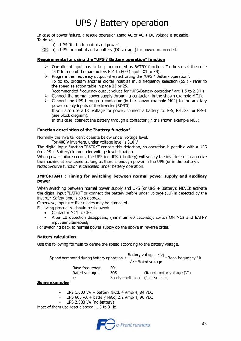
UPS / Battery operation In case of power failure, a rescue operation using AC or AC + DC voltage is possible. To do so,
a) a UPS (for both control and power) OR b) a UPS for control and a battery (DC voltage) for power are needed. Requirements for using the “UPS / Battery operation” function
One digital input has to be programmed as BATRY function. To do so set the code “34” for one of the parameters E01 to E09 (inputs X1 to X9). Program the frequency output when activating the “UPS / Battery operation”.
To do so, program another digital input as multi frequency selection (SSx) - refer to the speed selection table in page 23 or 25. Recommended frequency output values for “UPS/Battery operation” are 1.5 to 2.0 Hz. Connect the normal power supply through a contactor (in the shown example MC1). Connect the UPS through a contactor (in the shown example MC2) to the auxiliary
power supply inputs of the inverter (R0-T0). If you also use a DC voltage for power, connect a battery to: R-S, R-T, S-T or R-S-T (see block diagram). In this case, connect the battery through a contactor (in the shown example MC3).
Function description of the “battery function”
Normally the inverter can’t operate below under voltage level. For 400 V inverters, under voltage level is 310 V.
The digital input function “BATRY” cancels this detection, so operation is possible with a UPS (or UPS + Battery) in an under voltage level situation. When power failure occurs, the UPS (or UPS + battery) will supply the inverter so it can drive the machine at low speed as long as there is enough power in the UPS (or in the battery). Note: S-curve function is cancelled under battery operation. IMPORTANT : Timing for switching between normal power supply and auxiliary power
When switching between normal power supply and UPS (or UPS + Battery): NEVER activate the digital input “BATRY” or connect the battery before under voltage (LU) is detected by the inverter. Safety time is 60 s approx. Otherwise, input rectifier diodes may be damaged. Following procedure should be followed:
• Contactor MC1 to OFF. • After LU detection disappears, (minimum 60 seconds), switch ON MC2 and BATRY
input simultaneously. For switching back to normal power supply do the above in reverse order. Battery calculation
Use the following formula to define the speed according to the battery voltage.
k*frequency Basevoltage Rated
voltageBattery operationbattery during command Speed
2
5[V] - *
*≤
Base frequency: F04 Rated voltage: F05 (Rated motor voltage [V]) k: Safety coefficient (1 or smaller)
Some examples
- UPS 1.000 VA + battery NiCd, 4 Amp/H, 84 VDC - UPS 600 VA + battery NiCd, 2.2 Amp/H, 96 VDC - UPS 2.000 VA (no battery)
Most of them use rescue speed: 1.5 to 3 Hz

44
Block diagram
Timing chart
Input X(2) “SS, speed select”
Main power supply
MC 1
MC 2 / 3
Input X(1) “BATRY”
Inrush resistor
Battery power supply
DC link voltage
FWD/REV input (RUN)
Motor speed
Inrush
Control circuit
Converter
InverterR0
T0
N(-)
L1
L2
L3
U
V
W MotorPowerSupply
Battery
UPS
MC1
MC2
ControlSystem
Battery function
Rescue speedselection
RUN command
X(1) Input configured as “BATRY”
X(2) Input configured as “SS, speed select”
FWD/REW input
Resistor
EMCFilter
MC3
+
-
Inrush
Control circuit
Converter
InverterR0
T0
N(-)
L1
L2
L3
U
V
W MotorPowerSupply
Battery
UPSUPS
MC1
MC2
ControlSystem
Battery function
Rescue speedselection
RUN command
X(1) Input configured as “BATRY”
X(2) Input configured as “SS, speed select”
FWD/REW input
Resistor
EMCFilter
MC3
+
-

45
STARTING TORQUE COMPENSATION FUNCTION
Starting torque compensation Use this function to avoid the “Roll back”effect when the brake is released. The “Roll back” effect is due to that the system has a very reversible machine: i.e.: Gearless motor or geared motor with a high efficiency gear. The starting torque compensation is selected by function code o53. This function calculates the load torque from the acceleration when the brake is released, and compensates the torque output as the torque bias. If you use this function, please set the parameters included in the table below (with application values) When set frequency is 0 and operation command is turned ON, starting torque calculation begins. Parameters o50, o51 and o52 for the torque bias are effective also to this function. If o53=1, Starting torque compensation starts. Please, set the following application parameters so that this function works correctly.
C13: This value should be calculated by the following formula when the inverter rated operating frequency is f [Hz] and the elevator cage speed is v [m/min]. C13 = f / F03 * v C15: If you don’t know this value, please set 0.5 Kgm².

46
C17: See fig.1-1 Composition chat of elevator (below) Parameters o54, o55 and o56: i.e. Fast correction (smaller accuracy) i.e. Slow correction (bigger accuracy) (See below)
o54 = 1 (Calculation start pulse 1) o54 = 4 (Calculation start pulse 1) o55 = 2 (Calculation start pulse 2) o55 = 6 (Calculation start pulse 2) o56 = 2 (Pulse count) o56 = 4 (Pulse count) If these parameters are set as above, the inverter calculates the acceleration and rotor initial movement direction using the first and the second encoder pulses. The pulse count is the number of encoder pulses the inverter is using to do the calculation.
1 2 3 4 1 2 3 4
Calculation start pulse 1 (o54)
Calculation start pulse 2 (o55)
Pulse Count (o56) *
*
*

47
SECTION 4 Error code list
Alarm name Alarm code Alarm cause Possible causes
OC1 Over current during acceleration
To short acceleration time Brake not released Short circuit in the output circuit or ground fault
OC2 Over current during deceleration
Short circuit in the output circuit or ground fault
Over current
OC3 Over current during constant speed
Short circuit in the output circuit or ground fault
Ground fault NOTE : not for personal
protection. This is only for inverter protection
EF Only at inverters more then 22 kW. If ground fault is detected the EF protective function is activated
Fault in the inverter output circuit or fault in the cabling. Disconnect the motor cables and see if fault still is present.
OU1 DC bus over voltage during acceleration
Pulling load Brake resistor defect Contra weight not dimensioned right
OU2 DC bus over voltage during deceleration
To short deceleration time Brake resistor defect
Over voltage
OU3 DC bus over voltage at constant speed
Pulling load Brake resistor defect Contra weight not dimensioned right
Under voltage LU DC bus under voltage. Weak power supply Power failure Heavy acceleration Excessive load
Input open phase Lin Input phase loss Blown fuse in the supply line Loose terminal connection in the supply line
Heat sink overheat OH1 Heat sink to warm Cooling fan defect Installation place of inverter to warm
External alarm OH2 External alarm input off A input set to external fault (code 9) is off
Inverter internal overheat OH3 Inverter internal overheat Bad ventilation High ambient temperature
Braking resistor overheat dbH Calculated resistor overheat
The inverter has calculated that the use of the braking resistor is to high. (When function F13 is selected)
48
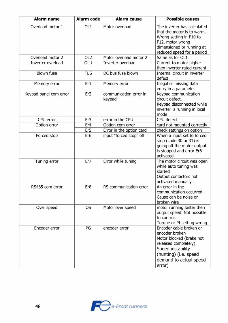
Alarm name Alarm code Alarm cause Possible causes
Overload motor 1 OL1 Motor overload The inverter has calculated that the motor is to warm. Wrong setting in F10 to F12, motor wrong dimensioned or running at reduced speed for a period
Overload motor 2 OL2 Motor overload motor 2 Same as for OL1 Inverter overload OLU Inverter overload Current to motor higher
then inverter rated current Blown fuse FUS DC bus fuse blown Internal circuit in inverter
defect Memory error Er1 Memory error Illegal or missing data
entry in a parameter Keypad panel com error Er2 communication error in
keypad Keypad communication circuit defect. Keypad disconnected while inverter is running in local mode
CPU error Er3 error in the CPU CPU defect Er4 Option com error card not mounted correctly Option error Er5 Error in the option card check settings on option
Forced stop Er6 input “forced stop” off When a input set to forced stop (code 30 or 31) is going off the motor output is stopped and error Er6 activated
Tuning error Er7 Error while tuning The motor circuit was open while auto tuning was started Output contactors not activated manually
RS485 com error Er8 RS communication error An error in the communication occurred. Cause can be noise or broken wire
Over speed OS Motor over speed motor running faster then output speed. Not possible to control. Torque or PI setting wrong
Encoder error PG encoder error Encoder cable broken or encoder broken Motor blocked (brake not released completely) Speed instability (hunting) (i.e. speed demand to actual speed error)
49
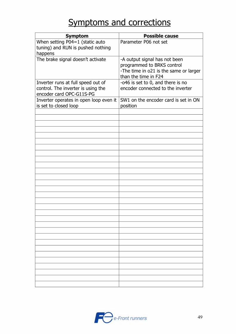
Symptoms and corrections
Symptom Possible cause When setting P04=1 (static auto tuning) and RUN is pushed nothing happens
Parameter P06 not set
The brake signal doesn’t activate -A output signal has not been programmed to BRKS control -The time in o21 is the same or larger than the time in F24
Inverter runs at full speed out of control. The inverter is using the encoder card OPC-G11S-PG
-o46 is set to 0, and there is no encoder connected to the inverter
Inverter operates in open loop even it is set to closed loop
SW1 on the encoder card is set in ON position

50
SECTION 5
Options
EMC filters Use this filter for comply to the EMC directive [400V series]
Inverter Applicable filter
Rated current Max voltage 3 phase
Dimensions L*W*H (mm)
FRN3,7G11S-4LE2 EFL-4,0G11-4 12 A 320*155*45 FRN5,5G11S-4LE2 FRN7,5G11S-4LE2 EFL-7,5G11-4 35 A 341*225*47,5
FRN11G11S-4LE2 FRN15G11S-4LE2 EFL-15G11-4 50 A 500*250*70
FRN18,5G11S-4LE2 FRN22G11S-4LE2 EFL-22G11-4 72 A
480 V
500*250*70
[200V series]
Inverter Applicable filter
Rated current Max voltage 3 phase
Dimensions L*W*H (mm)
FRN3,7G11S-2LE2 EFL-4,0G11-2 25 A 320*155*45 FRN5,5G11S-2LE2 FRN7,5G11S-2LE2 EFL-7,5G11-2 50 A 341*225*47,5
FRN11G11S-2LE2 FRN15G11S-2LE2 EFL-15G11-2 100 A 500*250*70
FRN18,5G11S-2LE2 FRN22G11S-2LE2 EFL-22G11-2 150 A
230 V
500*250*70
51
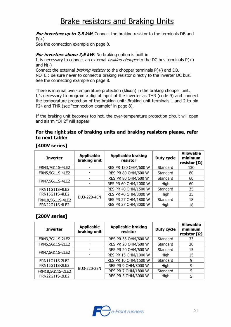
Brake resistors and Braking Units For inverters up to 7,5 kW: Connect the braking resistor to the terminals DB and P(+) See the connection example on page 8. For inverters above 7,5 kW: No braking option is built in. It is necessary to connect an external braking chopper to the DC bus terminals P(+) and N(-) Connect the external braking resistor to the chopper terminals P(+) and DB. NOTE : Be sure never to connect a braking resistor directly to the inverter DC bus. See the connecting example on page 8. There is internal over-temperature protection (klixon) in the braking chopper unit. It’s necessary to program a digital input of the inverter as THR (code 9) and connect the temperature protection of the braking unit: Braking unit terminals 1 and 2 to pin P24 and THR (see “connection example” in page 8). If the braking unit becomes too hot, the over-temperature protection circuit will open and alarm “OH2” will appear. For the right size of braking units and braking resistors please, refer to next table:
[400V series]
Inverter Applicable braking unit
Applicable braking resistor Duty cycle
Allowable minimum
resistor [Ω]FRN3,7G11S-4LE2 - RES PR 130 OHM/600 W Standard 130 FRN5,5G11S-4LE2 - RES PR 80 OHM/600 W Standard 80
- RES PR 80 OHM/600 W Standard 60 FRN7,5G11S-4LE2 - RES PR 60 OHM/1000 W High 60
RES PR 40 OHM/1500 W Standard 35 FRN11G11S-4LE2 FRN15G11S-4LE2 RES PR 40 OHM/3000 W High 35
RES PR 27 OHM/1800 W Standard 18 FRN18,5G11S-4LE2 FRN22G11S-4LE2
BU3-220-4EN
RES PR 27 OHM/3000 W High 18 [200V series]
Inverter Applicable braking unit
Applicable braking resistor Duty cycle
Allowable minimum
resistor [Ω]FRN3,7G11S-2LE2 - RES PR 33 OHM/600 W Standard 33 FRN5,5G11S-2LE2 - RES PR 20 OHM/600 W Standard 20
- RES PR 20 OHM/600 W Standard 15 FRN7,5G11S-2LE2 - RES PR 15 OHM/1000 W High 15
RES PR 10 OHM/1500 W Standard 9 FRN11G11S-2LE2 FRN15G11S-2LE2 RES PR 9 OHM/3000 W High 9
RES PR 7 OHM/1800 W Standard 5 FRN18,5G11S-2LE2 FRN22G11S-2LE2
BU3-220-2EN
RES PR 5 OHM/3000 W High 5
52
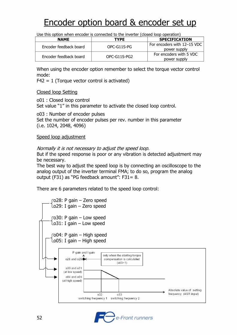
Encoder option board & encoder set up Use this option when encoder is connected to the inverter (closed loop operation)
NAME TYPE SPECIFICATION
Encoder feedback board OPC-G11S-PG For encoders with 12–15 VDC power supply
Encoder feedback board OPC-G11S-PG2 For encoders with 5 VDC power supply
When using the encoder option remember to select the torque vector control mode: F42 = 1 (Torque vector control is activated) Closed loop Setting
o01 : Closed loop control Set value “1” in this parameter to activate the closed loop control.
o03 : Number of encoder pulses Set the number of encoder pulses per rev. number in this parameter (i.e. 1024, 2048, 4096) Speed loop adjustment Normally it is not necessary to adjust the speed loop. But if the speed response is poor or any vibration is detected adjustment may be necessary. The best way to adjust the speed loop is by connecting an oscilloscope to the analog output of the inverter terminal FMA; to do so, program the analog output (F31) as “PG feedback amount”: F31= 8. There are 6 parameters related to the speed loop control:
o28: P gain – Zero speed o29: I gain – Zero speed o30: P gain – Low speed o31: I gain – Low speed o04: P gain – High speed o05: I gain – High speed
53
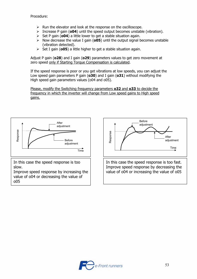
Procedure:
Run the elevator and look at the response on the oscilloscope. Increase P gain (o04) until the speed output becomes unstable (vibration). Set P gain (o04) a little lower to get a stable situation again. Now decrease the value I gain (o05) until the output signal becomes unstable
(vibration detected). Set I gain (o05) a little higher to get a stable situation again.
Adjust P gain (o28) and I gain (o29) parameters values to get zero movement at zero speed only if Starting Torque Compensation is calculated. If the speed response is poor or you get vibrations at low speeds, you can adjust the Low speed gain parameters P gain (o30) and I gain (o31) without modifying the High speed gain parameters values (o04 and o05). Please, modify the Switching frequency parameters o32 and o33 to decide the frequency in which the inverter will change from Low speed gains to High speed gains.
Afteradjustment
Beforeadjustment
Res
pons
e
Time
Res
pons
e
Beforeadjustment
Afteradjustment
Time
In this case the speed response is too slow. Improve speed response by increasing thevalue of o04 or decreasing the value of o05
In this case the speed response is too fast. Improve speed response by decreasing the value of o04 or increasing the value of o05

54
Speed deviation error
o44 and o45: These parameters define the allowed speed difference between commanded speed and actual speed (feedback) before speed error is active (PG error).
o44 : Speed detection width (% of commanded speed) o45 : Detection timer. o46 : Encoder abnormality function (defines what shall happen when speed deviation error is detected) When the relation between the commanded speed and the actual speed is ≥ o44, and this state continues during a period of time ≥ o45, inverter may trip (PG error) depending on o46:
o46=0: No trip (no PG error) Continue but with a warning o46=1: Inverter trips and motor coast to stop (display “PG”)
WARNING: 1. When using the OPC-G11S-PG and no encoder is connected, the inverter will run at full speed without control and with no error. 2. The switch SW1 on the encoder optional card has to be in OFF position. Otherwise the inverter will not detect the encoder pulses and will operate in open loop control.