full interrupt sequence...full interrupt sequence 37th lecture, dr. michael manzke, page: 2 full...
TRANSCRIPT
1
37th Lecture, Dr. Michael Manzke, Page: 1
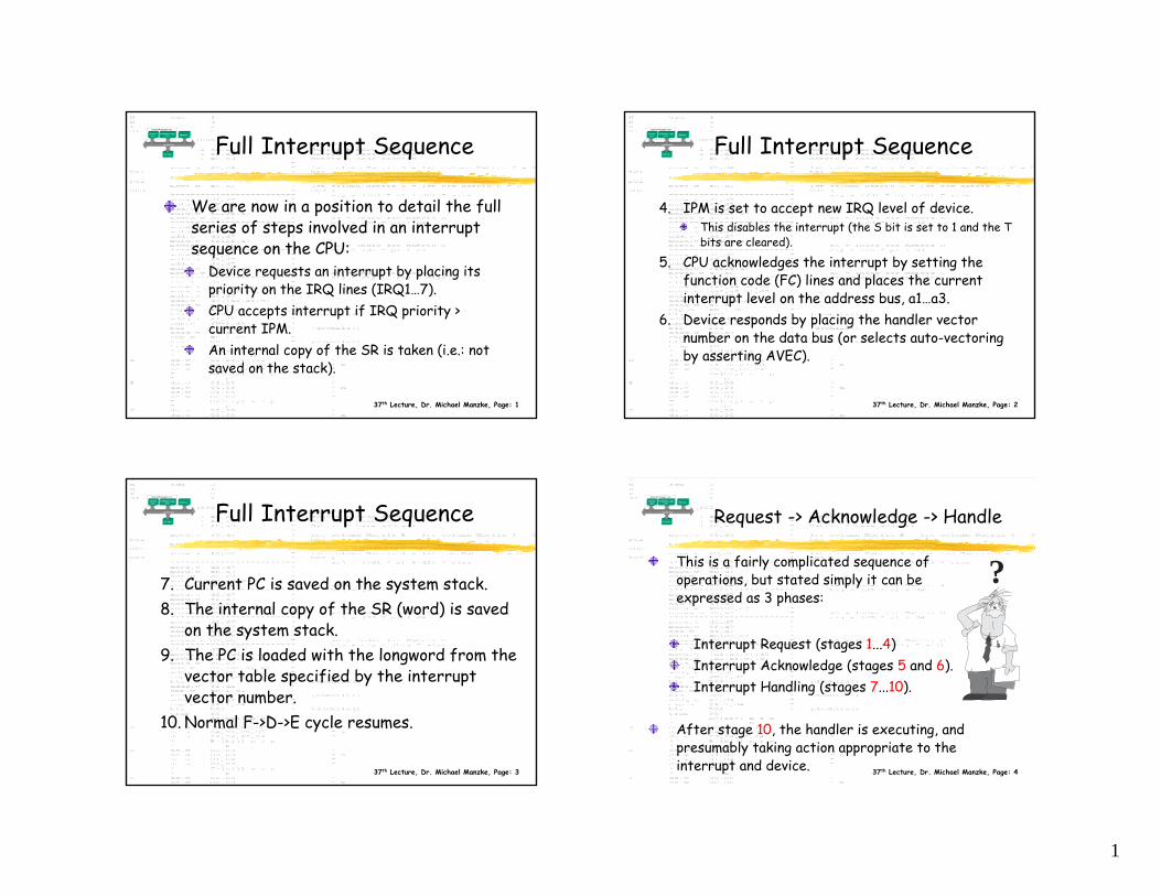
We are now in a position to detail the full series of steps involved in an interrupt sequence on the CPU:
Device requests an interrupt by placing its priority on the IRQ lines (IRQ1…7).CPU accepts interrupt if IRQ priority > current IPM.An internal copy of the SR is taken (i.e.: not saved on the stack).
Full Interrupt Sequence
37th Lecture, Dr. Michael Manzke, Page: 2
Full Interrupt Sequence
4. IPM is set to accept new IRQ level of device.This disables the interrupt (the S bit is set to 1 and the T bits are cleared).
5. CPU acknowledges the interrupt by setting the function code (FC) lines and places the current interrupt level on the address bus, a1…a3.
6. Device responds by placing the handler vector number on the data bus (or selects auto-vectoring by asserting AVEC).
37th Lecture, Dr. Michael Manzke, Page: 3
Full Interrupt Sequence
7. Current PC is saved on the system stack.8. The internal copy of the SR (word) is saved
on the system stack.9. The PC is loaded with the longword from the
vector table specified by the interrupt vector number.
10. Normal F->D->E cycle resumes.
37th Lecture, Dr. Michael Manzke, Page: 4
Request -> Acknowledge -> Handle
This is a fairly complicated sequence of operations, but stated simply it can be expressed as 3 phases:
Interrupt Request (stages 1...4)Interrupt Acknowledge (stages 5 and 6).Interrupt Handling (stages 7...10).
After stage 10, the handler is executing, and presumably taking action appropriate to the interrupt and device.
?
2
37th Lecture, Dr. Michael Manzke, Page: 5
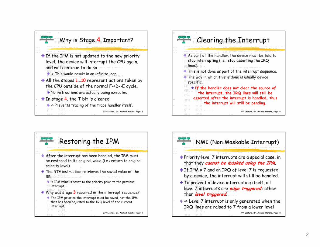
Why is Stage 4 Important?
If the IPM is not updated to the new priority level, the device will interrupt the CPU again, and will continue to do so.
-> This would result in an infinite loop.
All the stages 1...10 represent actions taken by the CPU outside of the normal F->D->E cycle.
No instructions are actually being executed.
In stage 4, the T bit is cleared:-> Prevents tracing of the trace handler itself.
37th Lecture, Dr. Michael Manzke, Page: 6
Clearing the Interrupt
As part of the handler, the device must be told to stop interrupting (i.e.: stop asserting the IRQ lines). This is not done as part of the interrupt sequence. The way in which this is done is usually device specific.
If the handler does not clear the source of the interrupt, the IRQ lines will still be
asserted after the interrupt is handled, thus the interrupt will still be pending.
37th Lecture, Dr. Michael Manzke, Page: 7
Restoring the IPM
After the interrupt has been handled, the IPM must be restored to its original value (i.e.: return to original priority level). The RTE instruction retrieves the saved value of the SR.
-> IPM value is reset to the priority prior to the previous interrupt.
Why was stage 3 required in the interrupt sequence?The IPM prior to the interrupt must be saved, not the IPM that has been adjusted to the IRQ level of the current interrupt.
37th Lecture, Dr. Michael Manzke, Page: 8
NMI (Non Maskable Interrupt)
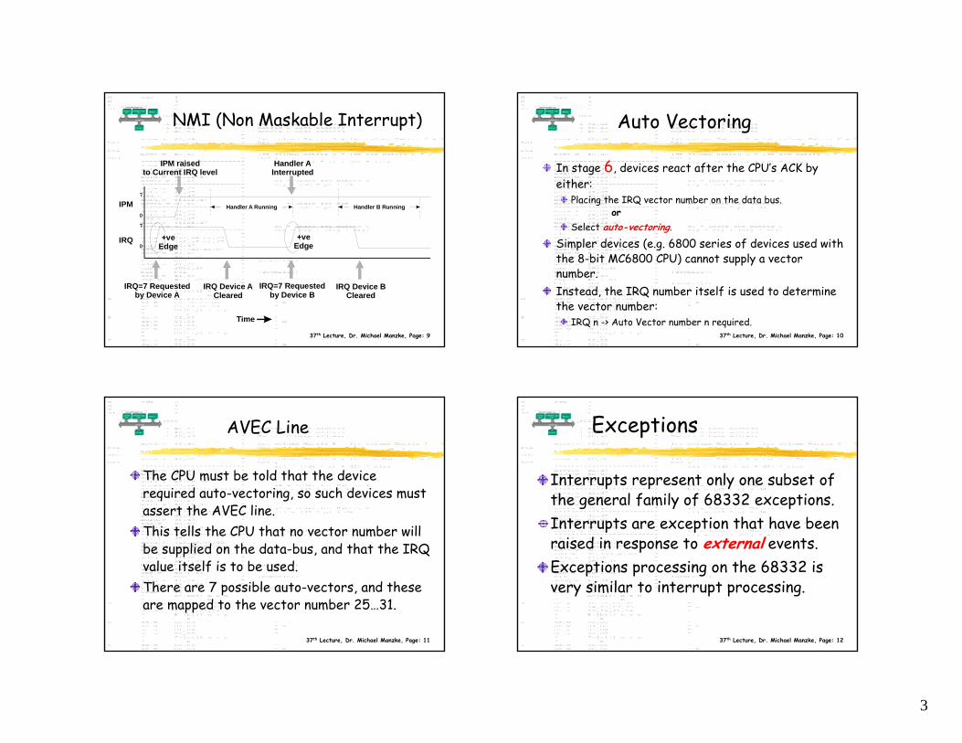
Priority level 7 interrupts are a special case, in that they cannot be masked using the IPM. If IPM = 7 and an IRQ of level 7 is requested by a device, the interrupt will still be handled.To prevent a device interrupting itself, all level 7 interrupts are edge triggered rather then level triggered.-> Level 7 interrupt is only generated when the IRQ lines are raised to 7 from a lower level
3
37th Lecture, Dr. Michael Manzke, Page: 9
NMI (Non Maskable Interrupt)
IPM
IRQ
0
7
0
7
Time
IRQ=7 Requestedby Device A
IRQ=7 Requestedby Device B
IRQ Device ACleared
IRQ Device BCleared
+veEdge
+veEdge
IPM raisedto Current IRQ level
Handler AInterrupted
Handler A Running Handler B Running
37th Lecture, Dr. Michael Manzke, Page: 10
Auto Vectoring
In stage 6, devices react after the CPU’s ACK by either:
Placing the IRQ vector number on the data bus. or
Select auto-vectoring.
Simpler devices (e.g. 6800 series of devices used with the 8-bit MC6800 CPU) cannot supply a vector number.Instead, the IRQ number itself is used to determine the vector number:
IRQ n -> Auto Vector number n required.
37th Lecture, Dr. Michael Manzke, Page: 11
AVEC Line
The CPU must be told that the device required auto-vectoring, so such devices must assert the AVEC line.This tells the CPU that no vector number will be supplied on the data-bus, and that the IRQ value itself is to be used.There are 7 possible auto-vectors, and these are mapped to the vector number 25…31.
37th Lecture, Dr. Michael Manzke, Page: 12
Exceptions
Interrupts represent only one subset of the general family of 68332 exceptions.Interrupts are exception that have been raised in response to external events.Exceptions processing on the 68332 is very similar to interrupt processing.
4
37th Lecture, Dr. Michael Manzke, Page: 13
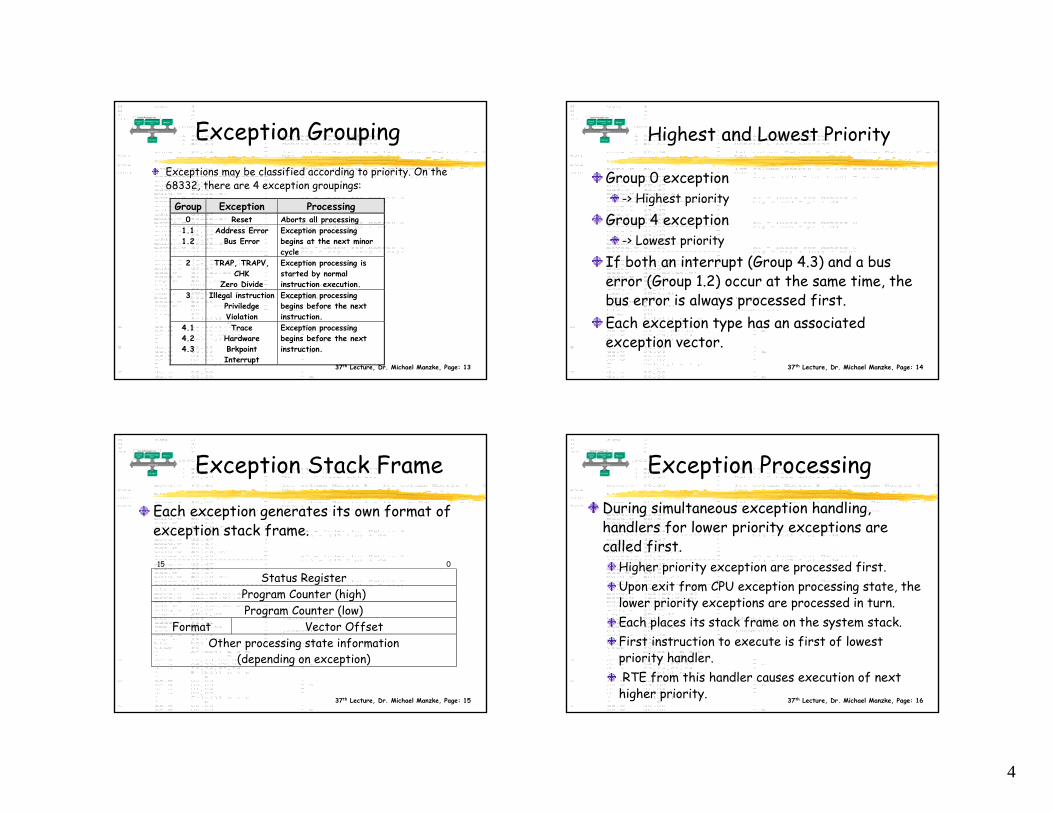
Exception GroupingExceptions may be classified according to priority. On the 68332, there are 4 exception groupings:
Group Exception Processing0 Reset Aborts all processing
1.11.2
Address ErrorBus Error
Exception processingbegins at the next minorcycle
2 TRAP, TRAPV,CHK
Zero Divide
Exception processing isstarted by normalinstruction execution.
3 Illegal instructionPriviledgeViolation
Exception processingbegins before the nextinstruction.
4.14.24.3
TraceHardwareBrkpointInterrupt
Exception processingbegins before the nextinstruction.
37th Lecture, Dr. Michael Manzke, Page: 14
Highest and Lowest Priority
Group 0 exception-> Highest priority
Group 4 exception-> Lowest priority
If both an interrupt (Group 4.3) and a bus error (Group 1.2) occur at the same time, the bus error is always processed first.Each exception type has an associated exception vector.
37th Lecture, Dr. Michael Manzke, Page: 15
Exception Stack Frame
Each exception generates its own format of exception stack frame.
15 0
Status RegisterProgram Counter (high)Program Counter (low)
Format Vector OffsetOther processing state information
(depending on exception)
37th Lecture, Dr. Michael Manzke, Page: 16
Exception ProcessingDuring simultaneous exception handling, handlers for lower priority exceptions are called first.
Higher priority exception are processed first.Upon exit from CPU exception processing state, the lower priority exceptions are processed in turn.Each places its stack frame on the system stack.First instruction to execute is first of lowest priority handler. RTE from this handler causes execution of next
higher priority.
5
37th Lecture, Dr. Michael Manzke, Page: 17
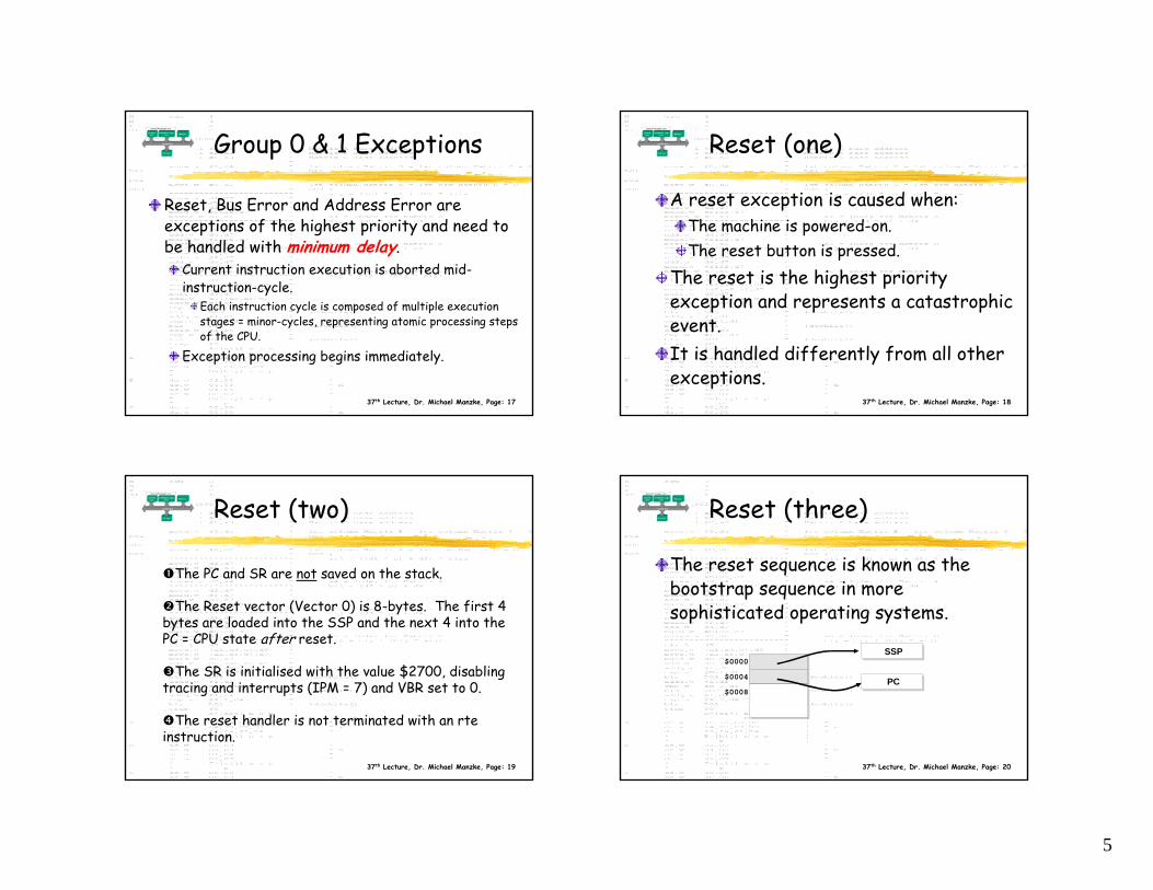
Group 0 & 1 Exceptions
Reset, Bus Error and Address Error are exceptions of the highest priority and need to be handled with minimum delay.
Current instruction execution is aborted mid-instruction-cycle.
Each instruction cycle is composed of multiple execution stages = minor-cycles, representing atomic processing steps of the CPU.
Exception processing begins immediately.
37th Lecture, Dr. Michael Manzke, Page: 18
Reset (one)
A reset exception is caused when:The machine is powered-on.The reset button is pressed.
The reset is the highest priority exception and represents a catastrophic event.It is handled differently from all other exceptions.
37th Lecture, Dr. Michael Manzke, Page: 19
Reset (two)
The PC and SR are not saved on the stack.
The Reset vector (Vector 0) is 8-bytes. The first 4 bytes are loaded into the SSP and the next 4 into the PC = CPU state after reset.
The SR is initialised with the value $2700, disabling tracing and interrupts (IPM = 7) and VBR set to 0.
The reset handler is not terminated with an rte instruction.
37th Lecture, Dr. Michael Manzke, Page: 20
Reset (three)
$0000
$0004
$0008
SSP
PC
The reset sequence is known as the bootstrap sequence in more sophisticated operating systems.
6
37th Lecture, Dr. Michael Manzke, Page: 21
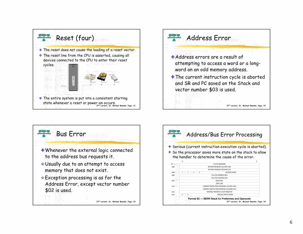
Reset (four)The reset does not cause the loading of a reset vector.The reset line from the CPU is asserted, causing all devices connected to the CPU to enter their reset cycles.
The entire system is put into a consistent starting state whenever a reset or power-on occurs.
MC68
332
Reset
Reset Reset Reset
37th Lecture, Dr. Michael Manzke, Page: 22
Address Error
Address errors are a result of attempting to access a word or a long-word on an odd memory address. The current instruction cycle is aborted and SR and PC saved on the Stack and vector number $03 is used.
37th Lecture, Dr. Michael Manzke, Page: 23
Bus Error
Whenever the external logic connected to the address bus requests it. Usually due to an attempt to access memory that does not exist.Exception processing is as for the Address Error, except vector number $02 is used.
37th Lecture, Dr. Michael Manzke, Page: 24
Address/Bus Error Processing
Serious (current instruction execution cycle is aborted). So the processor saves more state on the stack to allow the handler to determine the cause of the error.
7
37th Lecture, Dr. Michael Manzke, Page: 25
Address/Bus Error Processing
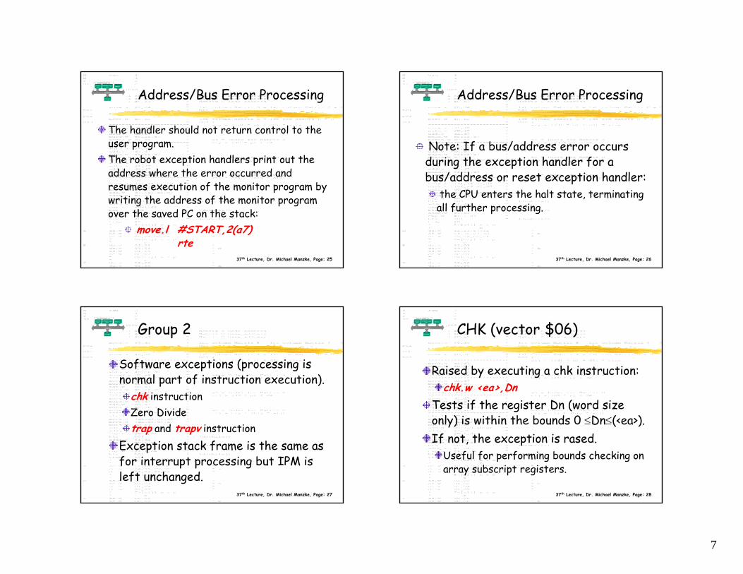
The handler should not return control to the user program.The robot exception handlers print out the address where the error occurred and resumes execution of the monitor program by writing the address of the monitor program over the saved PC on the stack:
move.l #START,2(a7) rte
37th Lecture, Dr. Michael Manzke, Page: 26
Address/Bus Error Processing
Note: If a bus/address error occurs during the exception handler for a bus/address or reset exception handler:
the CPU enters the halt state, terminating all further processing.
37th Lecture, Dr. Michael Manzke, Page: 27
Group 2
Software exceptions (processing is normal part of instruction execution).
chk instructionZero Dividetrap and trapv instruction
Exception stack frame is the same as for interrupt processing but IPM is left unchanged.
37th Lecture, Dr. Michael Manzke, Page: 28
CHK (vector $06)
Raised by executing a chk instruction:chk.w <ea>,Dn
Tests if the register Dn (word size only) is within the bounds 0 ≤Dn≤(<ea>).If not, the exception is rased.
Useful for performing bounds checking on array subscript registers.
8
37th Lecture, Dr. Michael Manzke, Page: 29
Zero Divide (vector $05)
Raised if the divs or divuinstruction are given a divisor
value of 0.
37th Lecture, Dr. Michael Manzke, Page: 30
Trap & Trapv
Certain instructions can only be executed in supervisor mode. Some hardware features may be in accessible in user mode.-> We need to provide a way for users to call routines that operate in supervisor mode, allowing access to all instruction and hardware.Example: Disk I/OA trap is a user generated exception. There are 16 trap vectors (vector 32…47) available for the 68332.
37th Lecture, Dr. Michael Manzke, Page: 31
Example
To raise a trap vector, the trap instruction is used:
move.l #1000,d0trap #13 *Delay, 1sec.trap #0 *Raise TRAP 0
37th Lecture, Dr. Michael Manzke, Page: 32
TRAPV
The trapv instruction is a conditional trap instruction that is raised only if the current overflow flag value is 1.
move.b #$7f,d0move.b #1,d1add.b d0,d1 *Overflowtrapv *trap will be taken
Vector used is number $07.-> Used to provide convenient error handlingduring arithmetic operations
9
37th Lecture, Dr. Michael Manzke, Page: 33
Using Traps
The address of the trap handler need not be known to the calling program/user.-> Address of the trap handler can change (by changing the vector table entry) without having to change the program invoking the trap.The trap handler becomes a numberedsubroutine.
37th Lecture, Dr. Michael Manzke, Page: 34
Protected Subroutines (1)
The address of the trap handler need not be known to the calling program/user.-> Address of the trap handler can change (by changing the vector table entry) without having to change the program invoking the trap.The trap handler becomes a numberedsubroutine.
37th Lecture, Dr. Michael Manzke, Page: 35
Protected Subroutines (2)
Traps allow access to instructions and resources available only in supervisor mode.A trap exception handler executes in supervisor mode, where user subroutines normally execute in user mode.-> Privilege violation whenever privileged instructions are executed.The trap handler is a protected subroutine.
37th Lecture, Dr. Michael Manzke, Page: 36
TRAP - Parameter Passing
Parameters may be passed to and from a trap handler just as you would for a subroutine with one exception:
You cannot pass back results in the CCR in the normal manner.
Why?The trap handler is terminated with an rte and not an rts.
-> The saved value of the SR is popped off the stack, thus destroying any parameter stored in the CCR.
10
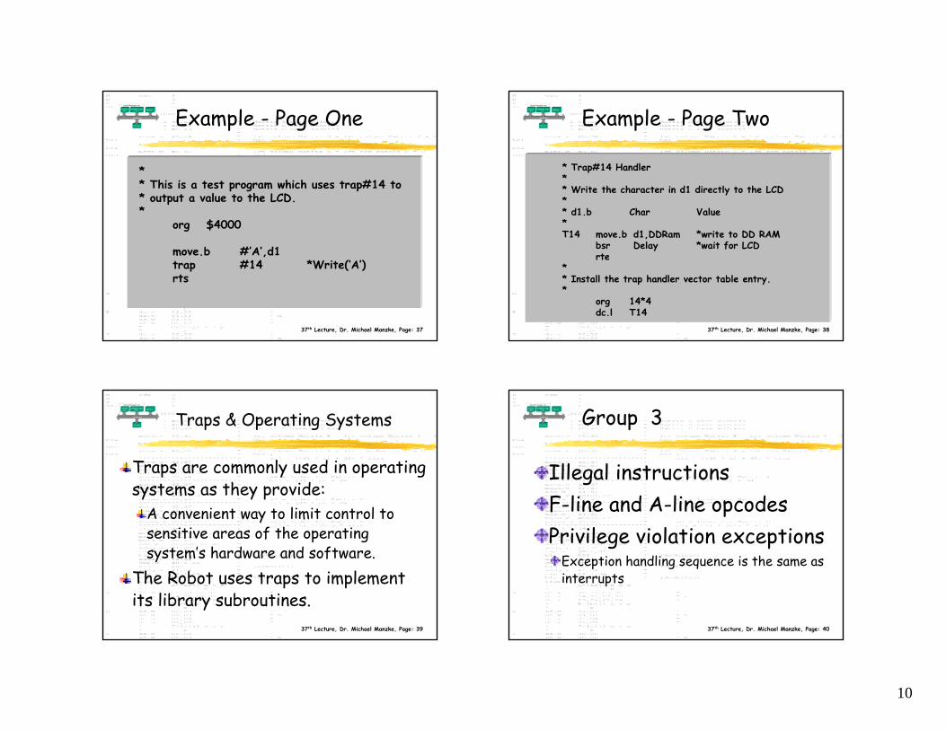
37th Lecture, Dr. Michael Manzke, Page: 37
Example - Page One
** This is a test program which uses trap#14 to* output a value to the LCD.*
org $4000
move.b #’A’,d1trap #14 *Write(‘A’)rts
37th Lecture, Dr. Michael Manzke, Page: 38
Example - Page Two
* Trap#14 Handler** Write the character in d1 directly to the LCD** d1.b Char Value*T14 move.b d1,DDRam *write to DD RAM
bsr Delay *wait for LCD rte
** Install the trap handler vector table entry.*
org 14*4dc.l T14
37th Lecture, Dr. Michael Manzke, Page: 39
Traps & Operating Systems
Traps are commonly used in operating systems as they provide:
A convenient way to limit control to sensitive areas of the operating system’s hardware and software.
The Robot uses traps to implement its library subroutines.
37th Lecture, Dr. Michael Manzke, Page: 40
Group 3
Illegal instructionsF-line and A-line opcodesPrivilege violation exceptions
Exception handling sequence is the same as interrupts
11
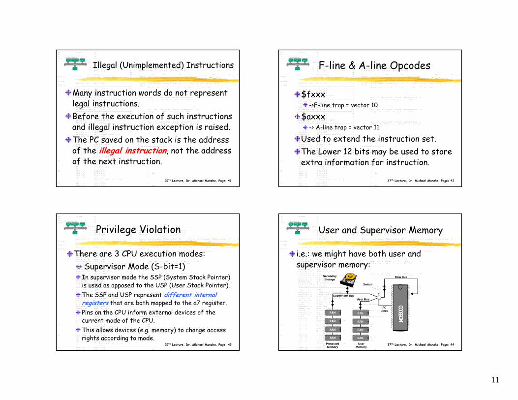
37th Lecture, Dr. Michael Manzke, Page: 41
Illegal (Unimplemented) Instructions
Many instruction words do not represent legal instructions.Before the execution of such instructions and illegal instruction exception is raised.The PC saved on the stack is the address of the illegal instruction, not the address of the next instruction.
37th Lecture, Dr. Michael Manzke, Page: 42
F-line & A-line Opcodes
$fxxx->F-line trap = vector 10
$axxx-> A-line trap = vector 11
Used to extend the instruction set.The Lower 12 bits may be used to store extra information for instruction.
37th Lecture, Dr. Michael Manzke, Page: 43
Privilege Violation
There are 3 CPU execution modes:Supervisor Mode (S-bit=1)
In supervisor mode the SSP (System Stack Pointer) is used as opposed to the USP (User Stack Pointer).The SSP and USP represent different internal registers that are both mapped to the a7 register.Pins on the CPU inform external devices of the current mode of the CPU.This allows devices (e.g. memory) to change access rights according to mode.
37th Lecture, Dr. Michael Manzke, Page: 44
User and Supervisor Memory
i.e.: we might have both user and supervisor memory:
MC68
000FC
Lines
Supervisor BusUser Bus
Data Bus
Switch
SecondayStorage
Protected Memory
UserMemory
RAM
RAM
RAM
RAM RAM
RAM
RAM
RAM
12
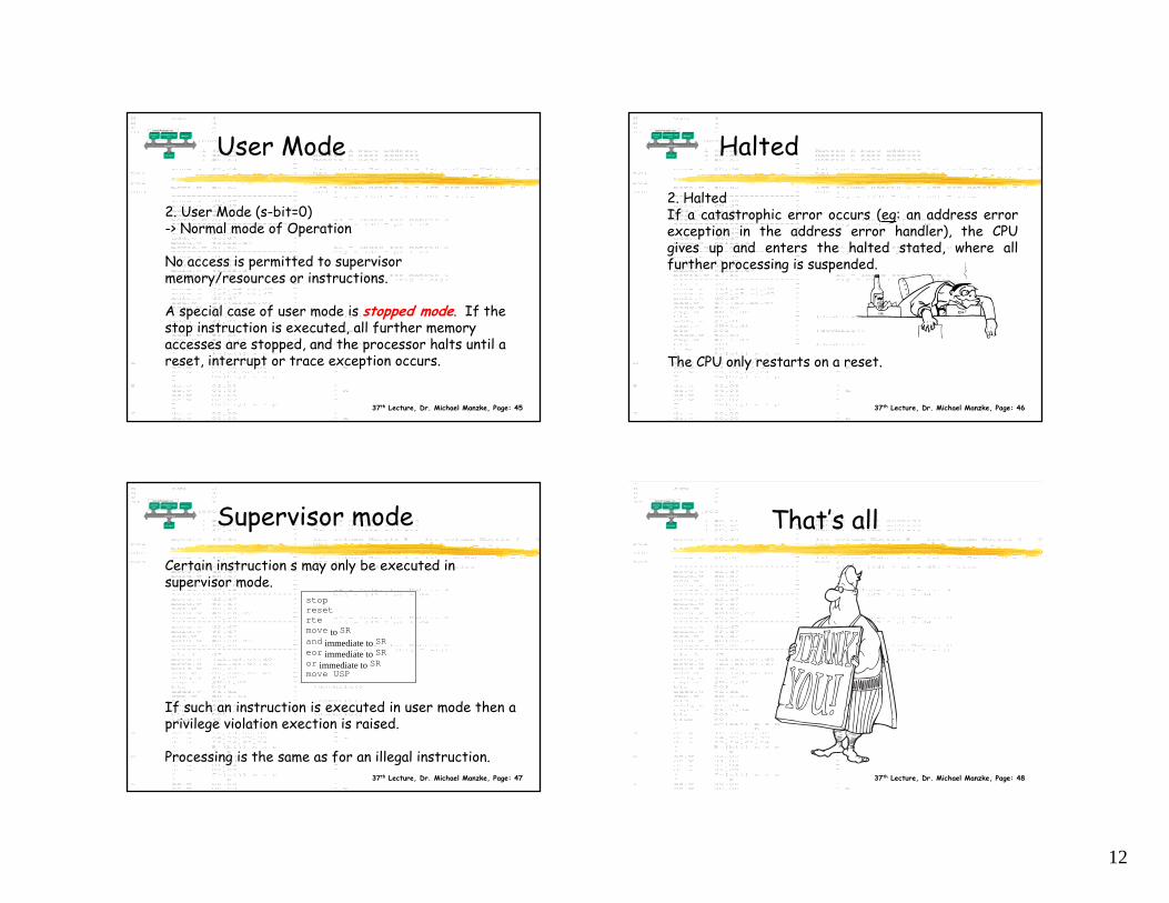
37th Lecture, Dr. Michael Manzke, Page: 45
User Mode
2. User Mode (s-bit=0)-> Normal mode of Operation
No access is permitted to supervisor memory/resources or instructions.
A special case of user mode is stopped mode. If the stop instruction is executed, all further memory accesses are stopped, and the processor halts until a reset, interrupt or trace exception occurs.
37th Lecture, Dr. Michael Manzke, Page: 46
Halted
2. HaltedIf a catastrophic error occurs (eg: an address error exception in the address error handler), the CPU gives up and enters the halted stated, where all further processing is suspended.
The CPU only restarts on a reset.
37th Lecture, Dr. Michael Manzke, Page: 47
Supervisor mode
Certain instruction s may only be executed in supervisor mode.
If such an instruction is executed in user mode then a privilege violation exection is raised.
Processing is the same as for an illegal instruction.
stopresetrtemove to SRand immediate to SReor immediate to SRor immediate to SRmove USP
37th Lecture, Dr. Michael Manzke, Page: 48
That’s all