full rf signal chains from 0hz to 110ghz
TRANSCRIPT

MEL CONWAY
Product Manager, Instrumentation
Full RF Signal Chains
from 0Hz to 110GHz
12/16/15
Agenda:
Antenna to Bits and Back
Spectrum Coverage
Equipment Examples
Signal Chains
Not Just RF
Good RF needs Good Power
More than Silicon
2
Background
►ADI is now #1 in RF world-wide
ADI is already #1 in Converters and #1 in Linear
►ADI acquired Hittite Microwave Corporation for $2B in 2014
►ADI capabilities now include:
the full signal chain, including companion products
full bandwidth from 0Hz (DC matters) to 110GHz
3
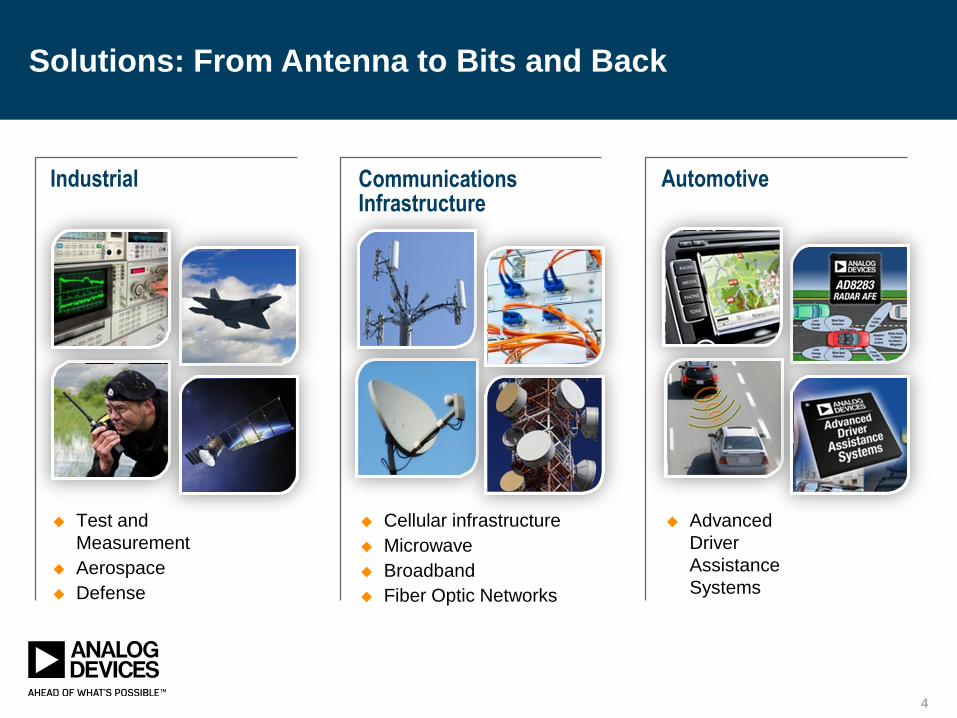
Cellular infrastructure
Microwave
Broadband
Fiber Optic Networks
CommunicationsInfrastructure
Test and
Measurement
Aerospace
Defense
Industrial
Advanced
Driver
Assistance
Systems
Automotive
Solutions: From Antenna to Bits and BackSolutions: From Antenna to Bits and Back
4
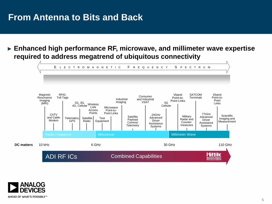
From Antenna to Bits and Back
► Enhanced high performance RF, microwave, and millimeter wave expertise
required to address megatrend of ubiquitous connectivity
E L E C T R O M A G N E T I C F R E Q U E N C Y S P E C T R U M
10 kHz 6 GHz 30 GHz 110 GHz
Magnetic Resonance
Imaging(MRI)
RFID,Toll Tags
2G, 3G, 4G, Cellular
Wireless LAN
Access Points
Microwave Point-to-
Point Links
SatellitePayloadComms/
Telemetry
24GHzAdvanced
DriverAssistance Systems
VbandPoint-to-
Point Links
SATCOMTerminals
Eband Point-to-
PointLinks
CATVand Cable
ModemTelematics,
GPSSatellite Radio
TestEquipment
Industrial Imaging
Consumerand Industrial
VSAT 5GCellular
MilitaryRadar and Counter-measures
77GHzAdvanced
Driver Assistance Systems
ScientificImaging and
Measurement
Combined Capabilities
Radio Frequency Microwave Millimeter Wave
ADI RF ICs
DC matters
5

Complete Signal Chain Solutions
Strategy Spans All Levels of Silicon System Integration
66

Analog Devices Has ALL Signal Processing Functions
7
X
~
X
LNA
RF Switches RF
Attenuators
Frequency
Conversion
Frequency
Conversion
PA
Frequency
Generation
ADC
Drivers ADC
DAC
Timing
Management
► ADI’s RF signal chain coverage has increased from 20% to almost 100%
7

Expanded Portfolio of Components and Solutions
► Switches which are smaller, lower insertion loss, higher isolation
► LNAs which are lower power, lower NF, and have better gain balance
► Passive Mixers – wide selection
► Passive Mixer LO Drivers (RF Gain Blocks)
► Passive Mixer Post Amplifiers (RF Gain Blocks)
► IF amplifiers that are lower power
► RF Gain Blocks
► Digital Step Attenuators
► Fixed Attenuators
► PLLs – World Class Noise Performance
► Passive Filters
► Wideband and Narrowband VCOs
► Doublers and Triplers
8

RF/Comms Test Equipment is a Key Growth Area for ADI
Backhaul Test
Equipment
5G
Standards
Development
Multi-Standard
Radio Test
40G
Short range
Comms
Test
Automotive Radar -> 77GHz
Solutions to Support Different Architectures
9
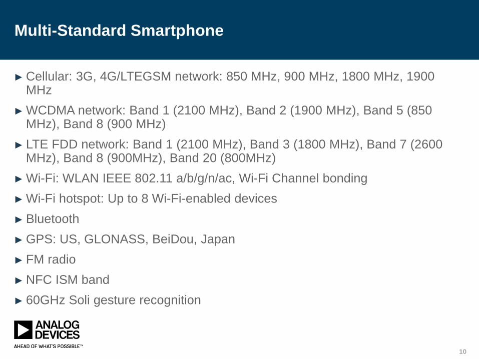
Multi-Standard Smartphone
► Cellular: 3G, 4G/LTEGSM network: 850 MHz, 900 MHz, 1800 MHz, 1900 MHz
► WCDMA network: Band 1 (2100 MHz), Band 2 (1900 MHz), Band 5 (850 MHz), Band 8 (900 MHz)
► LTE FDD network: Band 1 (2100 MHz), Band 3 (1800 MHz), Band 7 (2600 MHz), Band 8 (900MHz), Band 20 (800MHz)
► Wi-Fi: WLAN IEEE 802.11 a/b/g/n/ac, Wi-Fi Channel bonding
► Wi-Fi hotspot: Up to 8 Wi-Fi-enabled devices
► Bluetooth
► GPS: US, GLONASS, BeiDou, Japan
► FM radio
► NFC ISM band
► 60GHz Soli gesture recognition
10
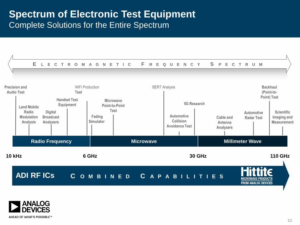
E L E C T R O M A G N E T I C F R E Q U E N C Y S P E C T R U M
10 kHz 6 GHz 30 GHz 110 GHz
Spectrum of Electronic Test EquipmentComplete Solutions for the Entire Spectrum
Precision and
Audio Test
Handset Test
Equipment
WiFi Production
Test
Microwave
Point-to-Point
Test
Automotive
Collision
Avoidance Test
Backhaul
(Point-to-
Point) Test
Land Mobile
Radio
Modulation
Analysis
Digital
Broadcast
Analyzers
Fading
Simulator
BERT Analysis
5G Research
Cable and
Antenna
Analyzers
Automotive
Radar Test
Scientific
Imaging and
Measurement
Radio Frequency Microwave Millimeter Wave
C O M B I N E D C A P A B I L I T I E SADI RF ICs
11
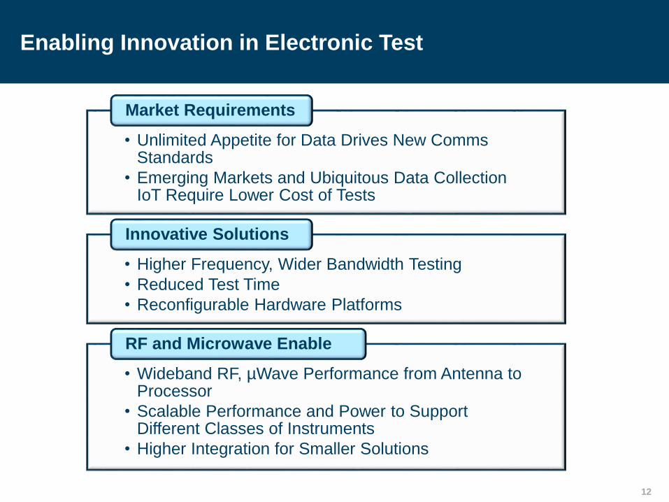
Enabling Innovation in Electronic Test
12
• Unlimited Appetite for Data Drives New Comms Standards
• Emerging Markets and Ubiquitous Data Collection IoT Require Lower Cost of Tests
Market Requirements
• Higher Frequency, Wider Bandwidth Testing
• Reduced Test Time
• Reconfigurable Hardware Platforms
Innovative Solutions
• Wideband RF, µWave Performance from Antenna to Processor
• Scalable Performance and Power to Support Different Classes of Instruments
• Higher Integration for Smaller Solutions
RF and Microwave Enable

HS & RF ETM Products
► Oscilloscope/DSO
► RF Power Meter
► Vector Signal Analyzer
► LCR meter
► Network Analyzer
► Signal and Spectrum Analyzers
► Signal Generators (synthesizers)
► Scanner / Receiver
► Direction Finder
► Modulation, Pulse Analyzer
► RF Source
► Vector Signal Generator
► EMI Test Receiver
► Broadband Amplifier
► EMS Test System
► Cable and Antenna Analyzer
► Simulator for: Bluetooth,
Basestation/BTS, WLAN, Cellular,
etc…
13
Vector Signal Analyzer
14

Vector Signal Analyzer
► A vector signal analyzer is an instrument that measures the magnitude
and phase of the measured signal at a single frequency within the range
of the instrument. Their primary use is to make in-channel measurements
on known signals, such as code domain power, error vector magnitude,
and spectral flatness. They are useful in measuring and demodulating
digitally modulated signals like cellular and wifi.
► ADI strengths here are: ADC drivers and ADCs, DDS, and clock
generation chips; our PLLs and VCOs dominate RF instrumentation and
of course our switches are everywhere.
15
Vector Signal Analyzer
(formerly Spectrum Analyzer)
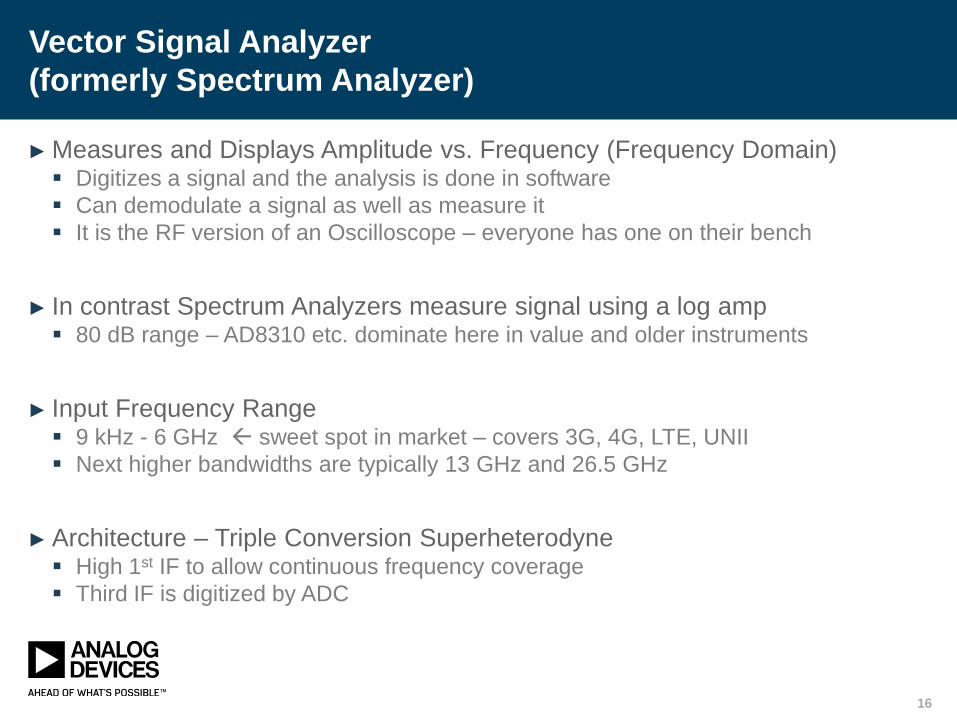
► Measures and Displays Amplitude vs. Frequency (Frequency Domain) Digitizes a signal and the analysis is done in software
Can demodulate a signal as well as measure it
It is the RF version of an Oscilloscope – everyone has one on their bench
► In contrast Spectrum Analyzers measure signal using a log amp 80 dB range – AD8310 etc. dominate here in value and older instruments
► Input Frequency Range 9 kHz - 6 GHz sweet spot in market – covers 3G, 4G, LTE, UNII
Next higher bandwidths are typically 13 GHz and 26.5 GHz
► Architecture – Triple Conversion Superheterodyne High 1st IF to allow continuous frequency coverage
Third IF is digitized by ADC
16

ADF4350/1
ADF5355
HMC832/3Vector Spectrum Analyzer (VSA)
17
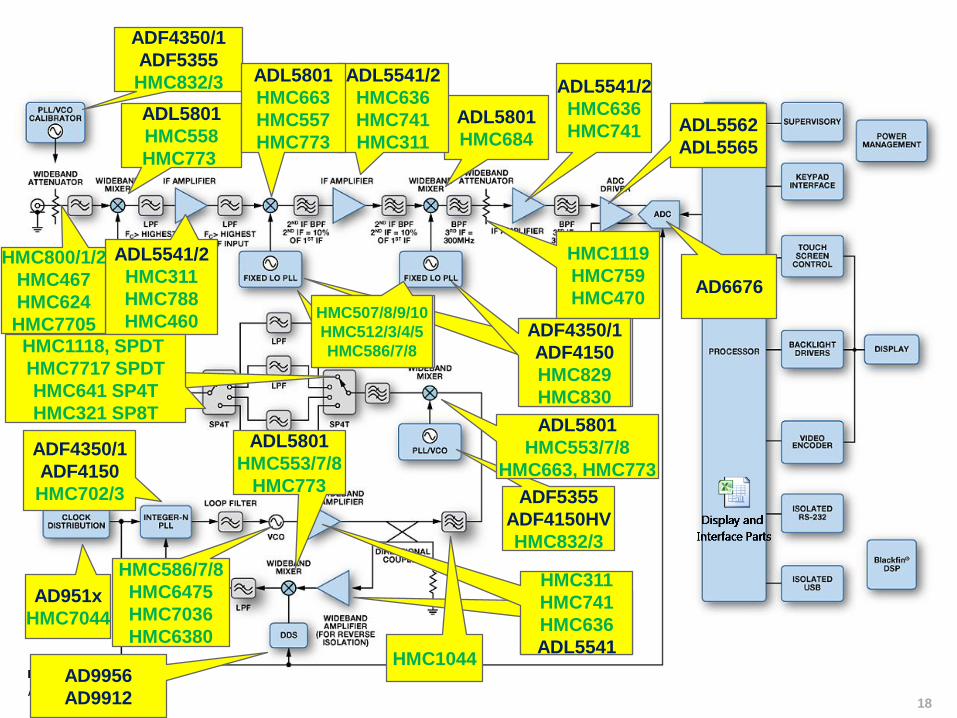
VSA After AcquisitionADF4350/1
ADF5355
HMC832/3
AD951x
HMC7044
AD9956
AD9912
ADF5355
ADF4150HV
HMC832/3
ADL5801
HMC684
ADL5801
HMC558
HMC773
ADL5562
ADL5565
ADL5541/2
HMC636
HMC741
ADF4350/1
ADF4150
HMC829
HMC830
ADF4350/1
ADF4150
HMC702/3
RF Gain
Blocks
HMC311
HMC741
HMC636
ADL5541
HMC321 SP8T
HMC232 SPDT
HMC344 SP4T
ADL5541/2
HMC311
HMC788
HMC460
ADL5541/2
HMC636
HMC741
HMC311
HMC800/1/2
HMC467
HMC624
HMC7705
ADL5801
HMC553/7/8
HMC663, HMC773
HMC1119
HMC759
HMC470
HMC1044
ADL5801
HMC553/7/8
HMC773
HMC586/7/8
HMC6475
HMC7036
HMC6380
HMC1118, SPDT
HMC7717 SPDT
HMC641 SP4T
HMC321 SP8T
HMC507/8/9/10
HMC512/3/4/5
HMC586/7/8
ADL5801
HMC663
HMC557
HMC773
AD6676
HMC507/8/9/10
HMC512/3/4/5
HMC586/7/8
ADF4350/1
ADF4150
HMC829
HMC830
18

VSA Solution Short-list
Product
Category Device Description
ADC AD6676 Wideband IF Receiver Subsystem
Amplifier HMC311 InGaP HBT Gain Block Amplifier, SMT, DC—6 GHz
HMC460 Low noise amplifiers, dc to 20 GHz
Attenuator HMC624A 0.5 dB LSB 6-Bit Digital Attenuator SMT, DC - 6 GHz
Clock AD9510 1.2 GHz Clock Distribution IC, PLL Core, Dividers, Delay Adjust, Eight Outputs
AD9511 1.2 GHz Clock Distribution IC, PLL Core, Dividers, Delay Adjust, Five Outputs
DDS AD9912
AD9956
1 GSPS Direct Digital Synthesizer with 14-Bit DAC
400 MSPS 14-Bit DAC 48-Bit FTW 1.8 V CMOS DDS Based AgileRF™ Synthesizer
Gain Block ADL5541 20 MHz to 6 GHz RF/IF Gain Block, Fixed Gain of 15 dB
MMIC HMC553 GaAsmonolithic microwave integrated circuit (MMIC)
PLL HMC702 14 GHz 16-bit Fractional-N PLL with Sweeper
PLL + VCO HMC829 Fractional-N PLL with Integrated VCO
HMC833 Fractional-N PLL with Integrated VCO, 25 - 6000 MHz
HMC832 Wideband PLL+VCO (3.3V), 25 - 3000 MHz
Switch HMC321 SP8T Positive Control Switch SMT, DC - 8 GHz
Synthesizer PLL ADF4150 Fractional-N/Integer-N PLL Synthesizer
Synthesizer with
VCO
ADF4350 Wideband Synthesizer with Integrated VCO
VCO HMC507 VCO SMT with Fo/2, 6.65 - 7.65 GHz
HMC508 VCO SMT with Fo/2, 7.3 - 8.2 GHz
HMC588 Wideband VCO SMT w/Buffer Amplifier, 8 - 12.5 GHz
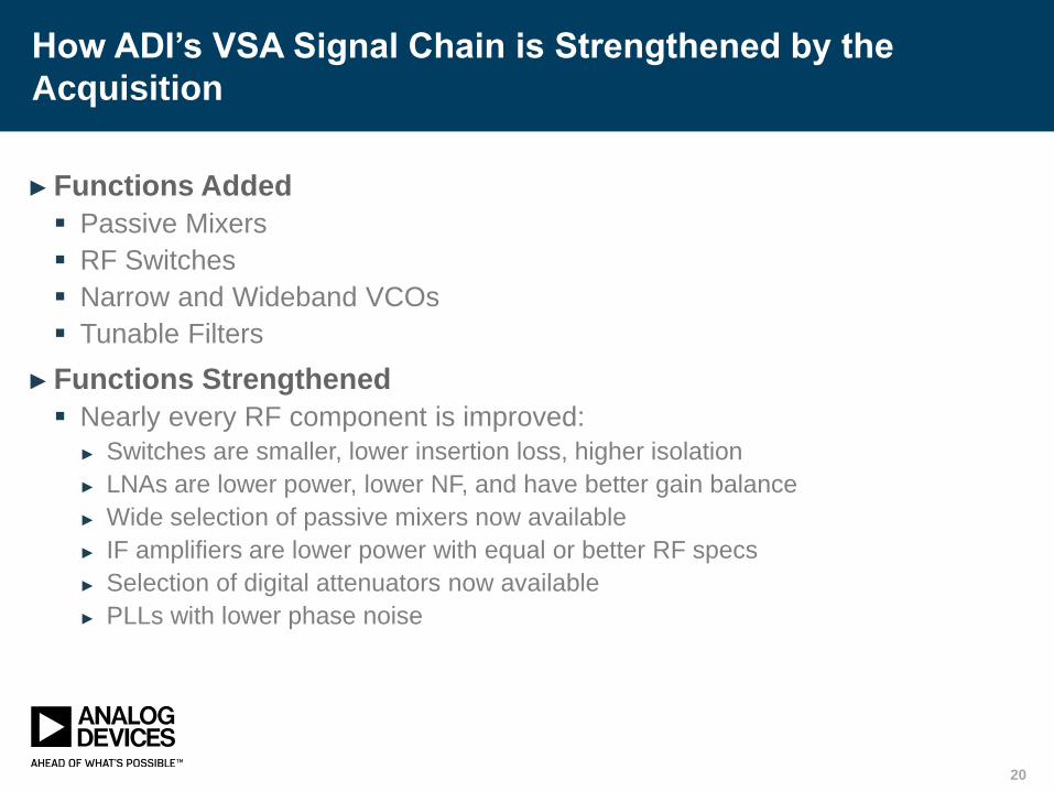
How ADI’s VSA Signal Chain is Strengthened by the
Acquisition
► Functions Added
Passive Mixers
RF Switches
Narrow and Wideband VCOs
Tunable Filters
► Functions Strengthened
Nearly every RF component is improved:
► Switches are smaller, lower insertion loss, higher isolation
► LNAs are lower power, lower NF, and have better gain balance
► Wide selection of passive mixers now available
► IF amplifiers are lower power with equal or better RF specs
► Selection of digital attenuators now available
► PLLs with lower phase noise
20

Synthesizer
► A synthesizer is an instrument to generate reference or comparison
signals to test various types of equipment, a synthesizer is also a common
block which is a very important part of many types of test and
measurement equipment such as: signal analyzers, network analyzers,
and modulated frequency synthesizers (also called vector signal
generators).
► ADI’s broad portfolio of high-speed and RF components includes: a wide
selection of passive mixers; narrow- and wide-band VCOs; tunable filters;
Switches which are smaller, lower insertion loss, higher isolation; power
detectors; doublers and triplers; digital attenuators; and PLLs with lower
phase noise.
21

Synthesizer Signal Chain Before The Acquisition
ADL5801
ADL5350
ADL5541
ADL5542HMC602
HMC611
ADL5519
ADL5902
HMC703
HMC704
HMC983/4
ADF4106
ADF41020
ADF4108
ADL5240
ADL5243
ADL5530/1
AD8353/4
ADC
RF
SWITCHRF
SWITCH
VCO
WIDEBAND
MIXER
RF GAIN
BLOCK
DIRECTIONAL
COUPLER
LOW PASS
FILTER
AMPLIFIER
OR
COMPARATOR
CLOCK
DISTRIBUTION DDSPLL
RF GAIN
BLOCKLOOP
FILTER
PLL
RF GAIN
BLOCKLOOP
FILTER
DIRECTIONAL
COUPLER
VCO
SYSTEM
CLOCK
REF
WIDEBAND
MIXER
PLL
RF GAIN
BLOCKLOOP
FILTER
DIRECTIONAL
COUPLER
VCO
RF GAIN
BLOCK
FILTER
BANKRF GAIN
BLOCK
DATT
RF
GAIN
BLOCK
POWER
DETECTOR
DIRECTIONAL
COUPLER
µC
RF
OUTPUT
RF
SWITCHRF
SWITCH
RF
DOUBLER
RF
POWER
AMPLIFIER
LOW PASS
FILTERRF GAIN
BLOCK
HMC311
HMC318
ADL5541
ADL5542
HMC311
HMC318
ADL5541
ADL5542
HMC311
HMC318
ADL5530/1
ADL5541/2
HMC321 SP8T
HMC232 SPDT
HMC344 SP4T
HMC1118 SPDT
HMC7717 SPDT
HMC321 SP8T
HMC232 SPDT
HMC344 SP4T
HMC1118 SPDT
HMC7717 SPDT
HMC321 SP8T
HMC232 SPDT
HMC344 SP4T
HMC1118 SPDT
HMC7717 SPDT
AD95xx
HMC1034/5
HMC311
HMC318
ADL5541
ADL5542
HMC311
HMC318
ADL5541
ADL5542
HMC
VCOs
HMC586
HMC587
HMC588
HMC586
HMC587
HMC588
HMC797
HMC998
HMC930
HMC994
ADL5801
HMC553
HMC557
HMC787
HMC1048
AD9912
AD9954
AD9956
22
ADF4106
ADF41020
ADF4108
HMC703
HMC704
HMC983/4
ADF4106
ADF41020
ADF4108

Oscilloscope (DSO scope meter)
► The oscilloscope is one of the most useful types of electronic test and
measurement equipment that continuously shows an electrical signal over
time, and which can often provide analysis and display of signal such as
amplitude, frequency, rise time, time interval, distortion, etc.
► ADI provides solutions across the complete oscilloscope from high-speed
converters to clocks, power and digital signal processing; also filters,
VGAs and PLL/VCOs.
23

DSO/Scope Meter
24
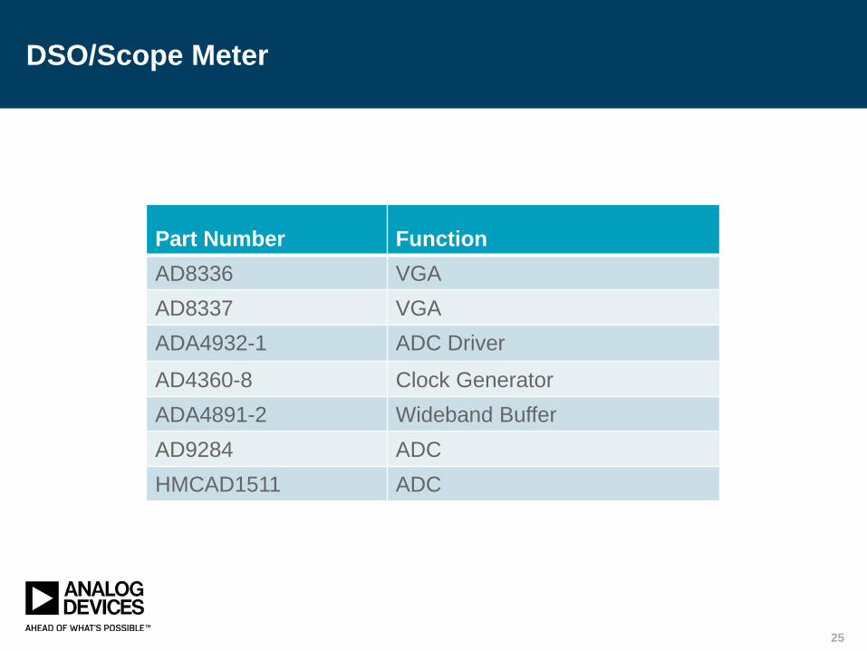
DSO/Scope Meter
Part Number Function
AD8336 VGA
AD8337 VGA
ADA4932-1 ADC Driver
AD4360-8 Clock Generator
ADA4891-2 Wideband Buffer
AD9284 ADC
HMCAD1511 ADC
25

RF&MW Control Products:
RF Switches and Attenuators
► ADI offers more than 1000 RF and MW,
components covering the entire RF and MW
signal chains and applications.
► Complete list of parts can be found on ADI
website www.analog.com
► RF&MW Control Product covers two families:
RF Switch Products
Attenuator Products
► RF switches and attenuators are often used in
the same application and has to comply with
similar system requirements.
26
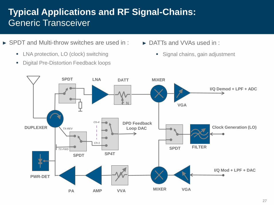
► SPDT and Multi-throw switches are used in :
LNA protection, LO (clock) switching
Digital Pre-Distortion Feedback loops
Typical Applications and RF Signal-Chains:
Generic Transceiver
27
► DATTs and VVAs used in :
Signal chains, gain adjustment
DATT
N
MIXERLNA
SPDT
PWR-DET
PA MIXER
VGA
FILTER
DUPLEXER
I/Q Demod + LPF + ADC
Clock Generation (LO)
I/Q Mod + LPF + DAC
VGAAMP VVA
SPDT
DPD Feedback
Loop DAC
Ch-1
TX-FWD
SPDT
SP4T
TX-REV
Ch-4
27

Low Frequency Operation
28
► GaAs : Limitations due to gate leakage current.
► Silicon : No gate leakage and high value resistors available
► Comparison of typical GaAs switch HMC849ALP4C vs Silicon switch HMC1118LP4ME
► The low frequency end covers 9KHz operation, making it ideal for T&M applications
HMC849ALP4C HMC1118LP4ME
28

Not Just the RF
► Converters – JESD204B
AD9625 12-Bit, 2.6 GSPS/2.5 GSPS/2.0 GSPS, Analog-to-Digital Converter
AD9691 14-Bit, 1.25 GSPS JESD204B, Dual Analog-to-Digital Converter
AD9684 14-Bit, 500 MSPS LVDS, Dual Analog-to-Digital Converter
AD9690 14-Bit, 500 MSPS / 1 GSPS JESD204B, Analog-to-Digital Converter
AD9152 Dual, 16-Bit, 2.25 GSPS, TxDAC+ Digital-to-Analog Converter
AD9154 Quad, 16-Bit, 2.4 GSPS, TxDAC+® Digital-to-Analog Converter
► Control and Biasing
► Power
29
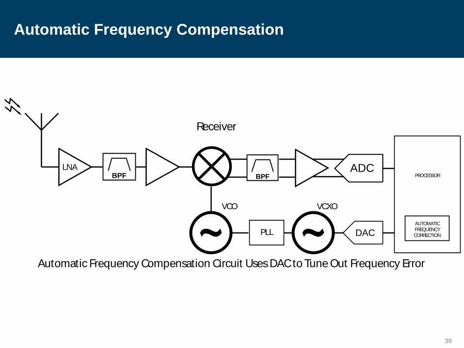
Automatic Frequency Compensation
Receiver
DAC
PROCESSOR
PLL
ADC
VCXO
BPF
VCO
AUTOMATIC
FREQUENCY
CORRECTION
BPF
LNA
Automatic Frequency Compensation Circuit UsesDACto TuneOut Frequency Error
30

VCO Tuning Voltage Start-up Before PLL Locks
LPF
DAC
R
N
PFD
CP
VCXO
DAC start-up tuning voltage for oscillator
before PLL loop locks.
31

Common-Mode Setting Between Stages
DAC
Set common mode voltage for next signal conversion stage.
Additional
RFStage
Requiring
DC BiasUp/Down Convert Stage
32

Adaptive Oscillator Drift Compensation
33
DAC
GPS
RECEIVER
ADAPTIVE
OSCILLATOR
MODEL
ACCOUNTS FOR OCXO
TEMP DRIFT AND AGING
IN ABSENCE OF GPS SIGNAL
CORRECTION
CALCULATOR
TEMP
SENSOR
DIGITAL
PHASE
DETECTOR
GPS
LOCK
DETECT
MUX

Amplifier (PHEMT ) Biasing
ADC
Vdd
Vgg
RFin RFout
DAC
MCU
HPA/LNA
Adjust gate voltage to ensure
correct current flow to amplifier drain
Current sense & ADC
Negative adjustable power supply
34

Good RF needs Good Power
35
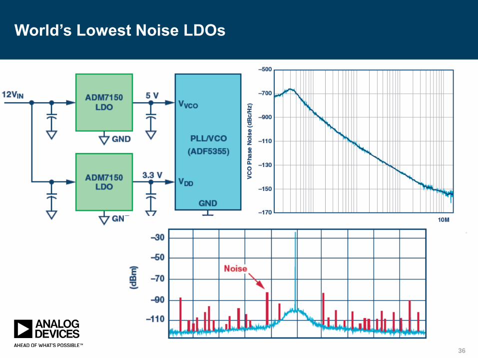
World’s Lowest Noise LDOs
36

Clean Power for Converters = Clean Signals
37

More than Silicon
► ADI supplies a full range of design resources to ease the development of
RF systems, including
free design tools
FMC rapid prototyping platforms
Circuits from the Lab® reference designs
EngineerZone® technical forums.
► Analog Design Tool: ADIsimRF™ is an easy-to-use RF signal chain
calculator.
It calculates Cascaded Gain, Noise Figure, IP3, P1dB and Power Consumption.
The number of stages can be varied up to a maximum of 20. Stages can be
easily inserted, removed or temporarily muted.
38

Summary
► ADI is now #1 in RF semiconductors
ADI acquired Hittite Microwave for $2B in 2014
► ADI can now capture up to 100% of RF signal chains
► ADI covers the complete frequency range from 0Hz to 110GHz
► ADI has more than 1,000 RF and µW parts
► ADI maintains leadership in Converters #1 and Linear #1
39
Thank You For Watching!
View Additional Webcasts at
www.analog.com/webcasts
Ask Questions on EngineerZone
ez.analog.com/community/webcast-qa