full-scale evaluation of ceramic membrane … · performance of the aasi ceramic membrane...
TRANSCRIPT

FULL-SCALE EVALUATION OF CERAMIC MEMBRANE FILTRATION FOR THE CITY OF ASHLAND, OREGON
DRINKING WATER TREATMENT PLANT
PILOT TEST REPORT
March 23, 2018
Testing conducted at:
CITY OF ASHLAND, OREGON WATER TREATMENT PLANT (WTP)
1400 Granite St.
Ashland, OR 97520
August 14, 2017 through December 14, 2017
AASI Project #100752A
© 2018 Aqua-Aerobic Systems, Inc.

Page 2 of 70 Department of Research and Development
Table of Contents 1. Objective ............................................................................................................................................... 6
2. Summary ............................................................................................................................................... 6
3. Background ......................................................................................................................................... 11
Figure 3-1: Simplified Diagram of Pilot Test Site Layout ..................................................................... 11
Table 3-1: Summary of Pilot Test Operating Conditions ..................................................................... 12
3.1 Raw water quality ....................................................................................................................... 13
3.1.1 Run 1 water quality ........................................................................................................................ 13
3.1.2 Run 2 water quality ........................................................................................................................ 13
3.1.3 Run 3 water quality ........................................................................................................................ 13
4. Test Equipment and Material ................................................................................................................. 14
Figure 4-1 Schematic Diagram of the CM-3 Pilot Testing System....................................................... 14
Table 4-1: Specifications of Ceramic Membrane ................................................................................ 15
Picture 4-1: Ceramic Membrane ......................................................................................................... 16
4.1 Operation and Maintenance ....................................................................................................... 19
Picture 4-2: AASI CM-3 Pilot Unit – Front view ................................................................................... 20
Picture 4-3: AASI CM-3 Pilot Unit – Rear View .................................................................................... 20
4.2 Process Description ..................................................................................................................... 21
Figure 4-2: Filtration and Backwash .................................................................................................... 21
Table 4-2: Typical CM-3 Membrane System Pilot Test Parameters ................................................... 22
4.3 System requirements .................................................................................................................. 24
5 Operation and Results......................................................................................................................... 24
Table 5-1: Clean Water Flux Test Results ............................................................................................ 24
Chart 5.1: Flux Comparison Between Design Runs 1-3 ....................................................................... 25
Table 5-1a: TMP Comparison Between CEBs for Design Runs 1-3 ..................................................... 25
5.1 CIP Results ................................................................................................................................... 25
5.1.1 Run 1 CIP results ..................................................................................................................... 26
Chart 5.1a: Run1 CIP Conducted Using TID Water .............................................................................. 26
5.1.2 Run 2 CIP results ..................................................................................................................... 27
Chart 5.1b: Run 2 CIP Conducted Using Reeder Reservoir Water ...................................................... 27
Table 5-2: Run 2 Post Acid CIP Results at Various Fluxes Using Reeder Reservoir Water .................. 27
Table 5-3: Run 2 Post Hypo CIP Results at Various Fluxes Using Reeder Reservoir Water ................ 27

Page 3 of 70 Department of Research and Development
5.1.3 Run 3 CIP results ............................................................................................................................ 28
Chart 5.1c: Run 3 CIP Conducted Using Reeder Reservoir Water ...................................................... 28
Table 5-4: Run 3 Post Acid CIP Results at Various Fluxes on Reeder Reservoir Water ....................... 28
Table 5-5: Run 3 Post Hypo CIP Results at Various Fluxes on Reeder Reservoir Water ..................... 28
Chart 5.1d: Comparison of CIP Results for All Three Runs .................................................................. 29
5.2 Design run 1 ................................................................................................................................ 29
Table 5-6 Operating Conditions Established During Design Run 1 ..................................................... 30
Chart 5.2a: TMP Baseline - Peak Analysis with No ACH Dose ............................................................. 31
Chart 5.2b Baseline and Peak TMP Analysis with 2 ppm ACH Dose After 9/17/2017 ........................ 31
5.2.1 Data Charts for Design Run 1 .................................................................................................. 32
Chart 5.2.1a: TMP Data for Design Run 1 on TID Water (psi) ............................................................ 32
Chart 5.2.1b: Flux and Flow Rate for Design Run 1 ............................................................................. 32
Chart 5.2.1c: Permeability for Design Run 1 (gfd/psi) ........................................................................ 33
Chart 5.2.1d: Feed Turbidity for Design Run 1 (NTU)* ....................................................................... 33
Chart 5.2.1e: Filtrate Turbidity for Design Run 1 (NTU) ...................................................................... 34
Chart 5.2.1f: Feed pH and Temperature for Design Run 1 ................................................................. 34
Chart 5.2.1g: CEB Results for Design Run 1......................................................................................... 35
5.3 Design Run 2 ............................................................................................................................... 35
Table 5-7 Operating Conditions Established During Design Run 2 ..................................................... 35
5.2.1 Data Charts for Design Run 2 ......................................................................................................... 36
Chart 5.3.1a: TMP Data for Design Run 2 (psi) ................................................................................... 36
Chart 5.3.1b: Flow and Flux Data for Design Run 2* .......................................................................... 37
Chart 5.3.1c: Permeability Data for Design Run 2 (gfd/psi)* .............................................................. 38
Chart 5.3.1d: Feed Turbidity Data for Design Run 2 ........................................................................... 38
Chart 5.3.1e: Filtrate Turbidity Data for Design Run 2........................................................................ 39
Chart 5.3.1f: Feed Temperature and pH Data for Design Run 2 ......................................................... 39
Chart 5.3.1g: CEB results for Design Run 2 ......................................................................................... 40
5.4 Design run 3 ................................................................................................................................ 40
Table 5-8 Operating Conditions Established During Design Run 3 ..................................................... 40
5.4.1 Data charts for Design run 3 ................................................................................................... 41
Chart 5.4.1a: TMP Data for Design Run 3 * ........................................................................................ 41
Chart 5.4.1b: Flow and Flux Data for Design Run 3 ............................................................................ 42

Page 4 of 70 Department of Research and Development
Chart 5.4.1c: Permeability Data for Design Run 3 (gfd/psi) ................................................................ 42
Chart 5.4.1d: Feed Turbidity Data for Design Run 3 (NTU) ................................................................. 43
Chart 5.4.1e: Filtrate Turbidity Data for Design Run 3 (NTU) ............................................................. 43
Chart 5.4.1f: Feed Temperature and pH Data for Design Run 3 ......................................................... 44
Chart 5.4.1g: PDT Result Data for Design Run 3 ................................................................................. 44
Chart 5.4.1h: CEB Results Data for Design Run 3 ................................................................................ 45
6. Discussion ............................................................................................................................................ 45
7. Conclusions ......................................................................................................................................... 48
8. 30-Year Life Cycle Cost ........................................................................................................................ 49
Table 8-1: 30-Year Present Worth of 8 MGD Ceramic Membrane System ........................................ 50
APPENDIX A: Clean-in-Place (CIP) Procedure .............................................................................................. 51
Figure A-1: Recirculation Flow Path .................................................................................................... 55
APPENDIX B: Chemically-Enhanced Backwash (CEB) Procedure ................................................................ 56
APPENDIX C: Integrity Test Procedure ........................................................................................................ 56
APPENDIX D: Certifications ......................................................................................................................... 57
APPENDIX E: Instrumentation Calibrations ................................................................................................. 57
APPENDIX F: PDT results and LRV calculations ........................................................................................... 58
Table F-1: Required Testing Pressure for Proper Resolution at Different Temperatures .................. 61
Table F-2: Summary of Testing Result for main skid ........................................................................... 65
Table F-3: Projection of LRV at Different Pressure Decay Rates ......................................................... 66
APPENDIX G: Chemicals used during testing .............................................................................................. 67
APPENDIX H: Equipment Summary for Full-Scale System .......................................................................... 68
APPENDIX I: Compressed Air Calculations for Full-Scale System ................................................................ 69
APPENDIX J: Chemical Calculations for Full-Scale System .......................................................................... 70

Page 5 of 70 Department of Research and Development
Abbreviations
AASI: Aqua-Aerobic Systems Inc.
ACH: Aluminum chlorohydrate
BW: Backwash
CEB: Chemically enhanced backwash
CIP: Clean-in-place
CMF: ceramic membrane filtration
CWFT: Clean water flux test
DOC: Dissolved organic carbon
HMI: Human-machine interface
MFEM: Membrane Filtration Equipment Manufacturer
MWJ: Metawater Japan
PDT: Pressure decay test
PLC: Programmable logic controller
TC: Temperature Corrected
TID: Talent Irrigation District
TMP: Trans-membrane pressure
TOC: Total organic carbon
WTP: Water treatment plant

Page 6 of 70 Department of Research and Development
1. Objective Aqua-Aerobic Systems Inc. (AASI) conducted a pilot test to demonstrate the performance of the AASI Ceramic Membrane Filtration (CMF) CM-3 pilot system in treating surface water for potable use at the CITY OF ASHLAND, OREGON WATER TREATMENT PLANT (WTP). This study was conducted from August to December 2017 and included three design runs. The first design run was conducted using water sourced from the Talent Irrigation District (TID). This water is considered to be difficult based on its higher total organic carbon (TOC) and turbidity. The second and third design runs were conducted using water sourced from the Reeder Reservoir. These two runs were distinguished by the second being a conservative run whereas the third run was conducted with an aggressive flux rate. The recorded data will be useful in projecting the full-scale design requirements to ensure sustained and reliable performance. The data from all three design runs are detailed and discussed in this report.
2. Summary AASI conducted three design run pilot tests at the City of Ashland, OR WTP using the CM-3 ceramic membrane pilot system. This report presents the results from all three design runs conducted at the Ashland WTP. Commissioning began during the week of August 14, 2017, and the first optimization period was conducted during the week of August 21, 2017.
Design run 1 began on August 30, 2017 and was completed on September 27, 2017. Operating conditions established during the optimization period for design run 1 were set at a flux of 50 gallons per ft2 membrane area per day (gfd), 45 minute filtration/backwash (BW) cycle times, and daily chemically-enhanced backwashes (CEBs) with one-hour soak. The starting baseline trans-membrane pressure (TMP) value was 3.5 psi, and ended at a lower TMP value of 2.2 psi (most likely attributed to the 2 ppm coagulant added to the pilot influent toward the end of the run, which was the only coagulant being added during run 1). TMP peaks (i.e., max TMP value between backwash events) ranged from 10-25 psi.

Page 7 of 70 Department of Research and Development
1The turbidity values are filtered to exclude the spiked values which were later determined to be due to air compressor induced vibrations. The filtrate turbidimeter was removed from the skid on 9/15/17. Spiking events were nearly eliminated; the few remaining spiking events were attributed to bubbling from vibrations affecting the filtrate tank. A bubble trap was installed on the feed side of the filtrate turbidimeter unit to minimize bubbling effects. This was done prior to starting design run 3.
A pressure decay test (PDT) was conducted daily; despite having some program issues in the first two weeks, the PDT was functional in the second half of design run 1. Total system recovery was 97%. Total reject rate (i.e., BW and CEB waste volumes as a percentage of feed volume) was 3%. Feed turbidity ranged between 5 and 201 NTU. Filtrate turbidity ranged between 0.01 and 0.091 NTU, and averaged 0.018 NTU. Feed pH remained stable at 7, and feed temperature ranged from 50 to 65 degrees Fahrenheit. Lastly, a clean-in-place (CIP) cleaning was performed prior to starting the 28 day test and directly after the test.
Design run 2 was conducted from October 3 to October 31, 2017. Operating conditions established during the optimization period for design run 2 were set at a flux of 50 gfd, 60-minute filtration/BW cycle time (later changed to 720 min), and daily CEB with one-hour soak. Starting baseline TMP value was 1.8 psi, with peaks ranging from 2–12 psi. Filtration time (i.e., BW frequency) was set at 60-minute intervals from 10/3 to 10/23/2017, but was later changed to 720-minute (12-hour) intervals from 10/23 to 10/31/17. The reasoning for this change was to increase percent recovery. Total system recovery was 98.3%. Total reject rate was 1.7%. Feed turbidity ranged between 0.2 and 21 NTU. Filtrate turbidity ranged between 0.002 and 0.051 NTU, and averaged 0.013 NTU. Feed pH averaged 7.3, and feed temperature ranged from 49–57 degrees Fahrenheit. A CIP was conducted upon completion of this test run.
Design run 3 was conducted from November 14 to December 12, 2017. Operating conditions established during the optimization period for design run 3 were set at a flux of 150 gfd, 90-minute filtration/BW cycle time, and a CEB every 3 days with a one-hour soak. Starting TMP value was 5.4 psi, with peaks ranging from 9.4–17 psi. Filtration time was set at 90-minute intervals. Total system recovery was 99.5%. Total reject rate was 0.5%. Feed turbidity ranged between 0.6 and 31 NTU. Filtrate turbidity ranged between 0.0018 and 0.081 NTU, and averaged 0.010 NTU. Feed pH averaged 7.1, and feed temperature ranged from 38–48 degrees Fahrenheit.

Page 8 of 70 Department of Research and Development
During the last part of run 2 (after 10/11/17) and all of run 3, the Owner was injecting 8 ppm of 50% aluminum chlorohydrate (ACH) coagulant into the raw water upstream of the three MFEM pilot systems. Coagulation enhances ceramic membrane filtration by reducing fouling potential and facilitates operation at a higher flux. In addition, all three runs operated with daily pressure decay tests (PDTs) (refer to Appendix C). Feed and filtrate turbidity data, feed pH, and feed temperature data were collected as well. Operating conditions and performance data from all test runs are detailed in section 5.
An average of 4.28 LRV was achieved during run 3, with a max LRV of 4.73 and a min LRV of 4.00. We encountered many difficulties with the PDT during run 1, both mechanically (i.e., air leaks via piping) as well as programmatically. Eventually, both issues were resolved for part of run 1. However, PDT data collection did not occur until Run 3 due to a program set up issue.
A clean-in-place (CIP) membrane cleaning was performed before and after each design run to demonstrate recovery of permeability, the results of which are presented in Section 5; refer to Appendix A for the CIP procedure used. The CIP consisted of two phases: a) 1% Citric Acid recirculation for 2 hours, followed by a 2 hour soak; and b) 0.03% NaOCl recirculation for 2 hours, followed by a 2 hour soak. The use of these chemicals, and their corresponding concentrations and membrane-exposure durations were established by Metawater as to be the most effective and efficient in restoring membrane baseline / permeability condition.
The chemical solutions for the first and second CIPs were heated to 80 deg Fahrenheit, but the third CIP was not heated.
To mitigate bio-fouling and enhance performance, a chemical-enhanced backwash (CEB) with one-hour soak was conducted daily during design run 1, weekly during part of design run 2, and every 3 days during design run 3; refer to Appendix B for the CEB procedure used. The CEBs alternated between two different sequences: one consisted of a 20-minute soak in hydrochloric acid (HCl, alternatively, H2SO4 can be used) at pH 1-2 followed by a 40-minute soak in sodium hypochlorite (NaOCl) at 0.01-0.03% (100–300 ppm), and the other consisted of a 60-minute soak in 0.01-0.03% NaOCl. Operational data were logged daily and can be provided upon request. A summary of the operating conditions are shown in Table 3-1. CEB

Page 9 of 70 Department of Research and Development
chemicals were not heated at any time throughout testing. The CEB recipe stated above has been established by Metawater on similar water applications. The CEB recipe can be optimized further for higher performance and/or lower consumption.
Based on these results, we recommend the full-scale system consist of (2) 12-row units with (10) modules per row, which will provide a total of 6,000 m2 (64,590 ft2) of membrane area, resulting in a flux of 124 gfd with all rows in service at 8 MGD and a flux of 129 gfd with one row out of service (each row has its own set of valves such that it can be operated totally independently of the other rows). We feel this approach is best for the following reasons:
• During Run 3, the pilot maintained stable operation at 150 gfd even though the Reeder Reservoir water TOC was the same as that of the TID source (2.9 ppm) and the water temperature was as low as 38 degrees Fahrenheit at a time of year when flows are typically less than 30% of design1. It’s expected that even higher fluxes are possible in the summer months at higher water temperatures.
• Even in the drought of 2014, the TID water source made up only 17% of the total supply2, most of it used during the warm summer months when higher fluxes are possible.
• During Run 1, the pilot maintained stable operation at 50 gfd even though the TID water turbidity was as high as 20 NTU at 54 degrees Fahrenheit and there was little to no coagulant addition. This run also demonstrated that operation became much more stable with as little as 2 ppm of 50% ACH (0.25 ppm as Al); we would expect to run at a much higher flux had the coagulant dosage been at the 8 ppm (as 50% ACH) that was used during Run 3 and the end of Run 2.
Based on the conditions used in Run 3 (at the lowest water temperatures), we recommend using the following operating parameters during the 7 colder months. Note that the backwash/filtration and CEB intervals are double those
1 From Figure 4.3 of the City of Ashland Comprehensive Water Master Plan, adopted April 17, 2012. 2 See the data for 2014 on Figure 1 in Appendix A of the WATER QUALITY ANALYSIS AND TREATMENT PROCESS SELECTION, drafted July 2017
Page 10 of 70 Department of Research and Development
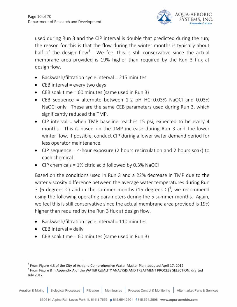
used during Run 3 and the CIP interval is double that predicted during the run; the reason for this is that the flow during the winter months is typically about half of the design flow3. We feel this is still conservative since the actual membrane area provided is 19% higher than required by the Run 3 flux at design flow.
• Backwash/filtration cycle interval = 215 minutes • CEB interval = every two days • CEB soak time = 60 minutes (same used in Run 3) • CEB sequence = alternate between 1-2 pH HCl-0.03% NaOCl and 0.03%
NaOCl only. These are the same CEB parameters used during Run 3, which significantly reduced the TMP.
• CIP interval = when TMP baseline reaches 15 psi, expected to be every 4 months. This is based on the TMP increase during Run 3 and the lower winter flow. If possible, conduct CIP during a lower water demand period for less operator maintenance.
• CIP sequence = 4-hour exposure (2 hours recirculation and 2 hours soak) to each chemical
• CIP chemicals = 1% citric acid followed by 0.3% NaOCl
Based on the conditions used in Run 3 and a 22% decrease in TMP due to the water viscosity difference between the average water temperatures during Run 3 (6 degrees C) and in the summer months (15 degrees C)4, we recommend using the following operating parameters during the 5 summer months. Again, we feel this is still conservative since the actual membrane area provided is 19% higher than required by the Run 3 flux at design flow.
• Backwash/filtration cycle interval = 110 minutes • CEB interval = daily • CEB soak time = 60 minutes (same used in Run 3)
3 From Figure 4.3 of the City of Ashland Comprehensive Water Master Plan, adopted April 17, 2012. 4 From Figure 8 in Appendix A of the WATER QUALITY ANALYSIS AND TREATMENT PROCESS SELECTION, drafted July 2017.

Page 11 of 70 Department of Research and Development
• CEB sequence = alternate between 1-2 pH HCl-0.03% NaOCl and 0.03% NaOCl only. These are the same CEB parameters used during Run 3, which significantly reduced the TMP.
• CIP interval = when TMP baseline reaches 15 psi, expected to be every 90 days. This is based on the TMP increase during Run 3 and the lower baseline TMP expected in the summer months. If possible, conduct CIP during a lower water demand period for less operator maintenance.
• CIP sequence = 4-hour exposure (2 hours recirculation and 2 hours soak) to each chemical
• CIP chemicals = 1% citric acid followed by 0.3% NaOCl
3. Background The pilot test occurred on-site at the City of Ashland, OR water treatment plant (WTP). The purpose of pilot testing was to evaluate the performance of the AASI CM-3 ceramic membrane filtration system which would be integrated into the implementation of a new WTP for The City of Ashland, OR.
The feed supply to the membrane filtration systems was sourced from both the Reeder Reservoir and Talent Irrigation District. The pilot tests were conducted outdoors under a tent at The City of Ashland, OR, WTP, at 1400 Granite St, Ashland, OR. A simplified diagram of the test site layout is shown in Figure 3-1.
Figure 3-1: Simplified Diagram of Pilot Test Site Layout
Coagulant Injection
H2O Pall AASI
Feed flow

Page 12 of 70 Department of Research and Development
Table 3-1: Summary of Pilot Test Operating Conditions
Parameter Design run 1 (8/30/2017 to 9/27/2017)
Design run 2 (10/03/2017 to 10/31/2017)
Design run 3 (11/14/2017 to 12/12/2017)
a) Coagulant injection
2 ppm 50% ACH into CM-3 unit mix tank5 From 9/16 to 9/27/17. Prior to this and during, no other coagulant was dosed
8 ppm 50% ACH(Owner- injected) from 10/ 125 to 10/31; No coagulant was added from 10/03 to 10/12
8 ppm ACH (Owner-injected) – added throughout test run as common to all MFEMs
b) Filtration cycle /Backwash interval
45 minutes 60 minutes (increased to 720 minutes for the last 1/3 of test)
90 minutes
c) Flux (gfd) 50 50 150 d) Feed flow (gpm) 9.3 9.3 28 e) CEB cycle
frequency 1x/day, alternating between acid-oxidant and oxidant only
1x/day Oct 3-22, 1x/week Oct 23-31 (all alternating)
1x/3 days, alternating between acid-oxidant and oxidant only
f) CEB soak time 60 minutes total (split between acid and hypo CEBs) g) Acid CEB HCl to 1-2 pH, 20-minute soak every other CEB; not heated h) Oxidant CEB 0.03% NaOCl , alternating between 40- and 60-minute soak;
not heated i) CIP cycle 28 days j) Acid CIP 1% citric acid for 4 hours (2-hour recirculation, 2-hour soak)
heated to 80° F after test runs 1 and 2, but not after test run 3 k) Oxidant CIP 0.3% NaOCl for 4 hours (2-hour recirculation, 2-hour soak),
heated to 80° F after test runs 1 and 2, but not after test run 3
5 The intent of the WTP was to inject 8 ppm of 50% ACH upstream of the three MFEM pilots, but it was found on October 12 that no coagulant had been injected due to malfunction of the plant’s ACH feed system.
Page 13 of 70 Department of Research and Development
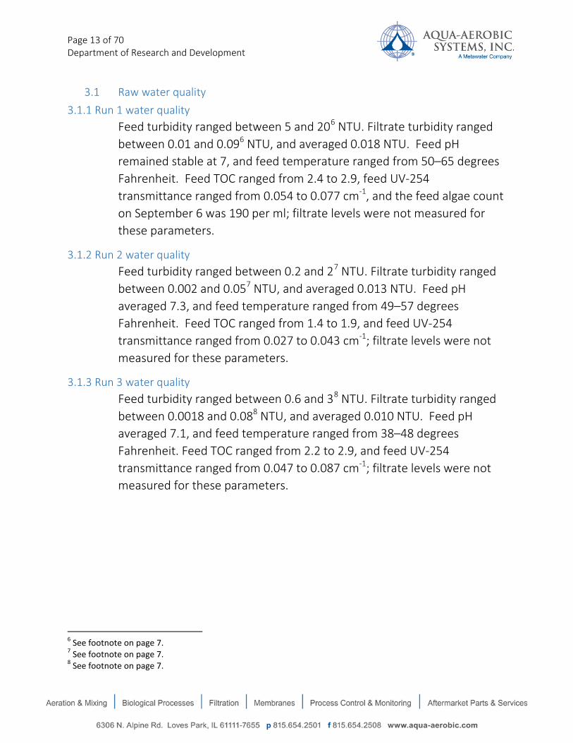
3.1 Raw water quality 3.1.1 Run 1 water quality
Feed turbidity ranged between 5 and 206 NTU. Filtrate turbidity ranged between 0.01 and 0.096 NTU, and averaged 0.018 NTU. Feed pH remained stable at 7, and feed temperature ranged from 50–65 degrees Fahrenheit. Feed TOC ranged from 2.4 to 2.9, feed UV-254 transmittance ranged from 0.054 to 0.077 cm-1, and the feed algae count on September 6 was 190 per ml; filtrate levels were not measured for these parameters.
3.1.2 Run 2 water quality Feed turbidity ranged between 0.2 and 27 NTU. Filtrate turbidity ranged between 0.002 and 0.057 NTU, and averaged 0.013 NTU. Feed pH averaged 7.3, and feed temperature ranged from 49–57 degrees Fahrenheit. Feed TOC ranged from 1.4 to 1.9, and feed UV-254 transmittance ranged from 0.027 to 0.043 cm-1; filtrate levels were not measured for these parameters.
3.1.3 Run 3 water quality Feed turbidity ranged between 0.6 and 38 NTU. Filtrate turbidity ranged between 0.0018 and 0.088 NTU, and averaged 0.010 NTU. Feed pH averaged 7.1, and feed temperature ranged from 38–48 degrees Fahrenheit. Feed TOC ranged from 2.2 to 2.9, and feed UV-254 transmittance ranged from 0.047 to 0.087 cm-1; filtrate levels were not measured for these parameters.
6 See footnote on page 7. 7 See footnote on page 7. 8 See footnote on page 7.

Page 14 of 70 Department of Research and Development
4. Test Equipment and Material Figure 4-1 shows a schematic diagram of the CM-3 pilot system. The pilot system is equipped with a ceramic membrane that was used for the pilot test.
*A strainer was not used on the CM-3 system during testing.
Figure 4-1 Schematic Diagram of the CM-3 Pilot Testing System
The AASI/MWJ ceramic membrane element is made of alumina-based ceramic material. Its robust properties allow it to operate with a longer membrane life than other membrane types due to its high chemical and thermal resistance and mechanical strength. Higher concentrations of chemical are applicable for cleaning which permits consistent permeability recovery over extended operational periods. Due to a tight pore size distribution, the AASI/MWJ ceramic membranes have higher permeability and less pressure loss across each membrane unit in comparison to polymeric membrane media.
The specifications of the ceramic membrane element used in the study are presented in Table 4-1, and are further illustrated in Picture 4-1. The monolith body of each ceramic membrane measures about 7.1 inches diameter and 59.1 inches long. The nominal pore size is 0.1 micron with a total of 269 ft2 membrane
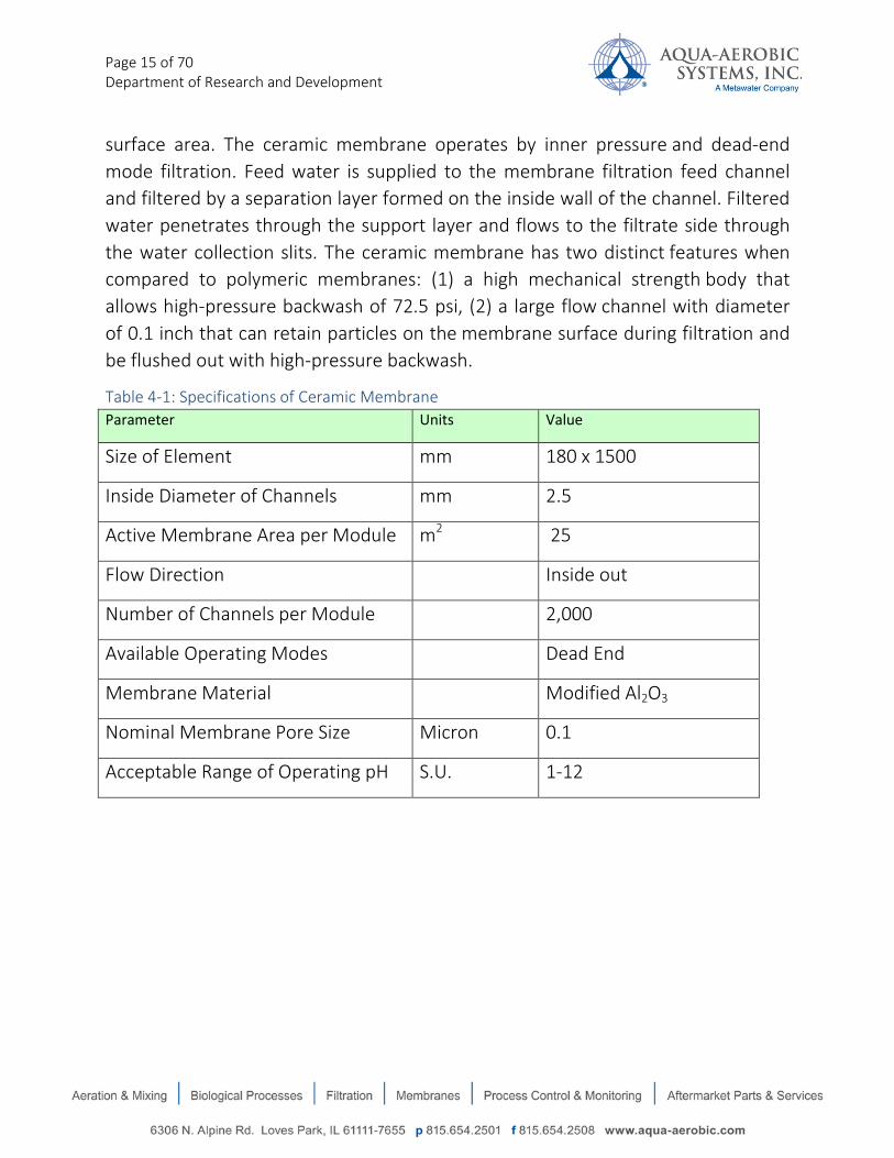
Page 15 of 70 Department of Research and Development
surface area. The ceramic membrane operates by inner pressure and dead-end mode filtration. Feed water is supplied to the membrane filtration feed channel and filtered by a separation layer formed on the inside wall of the channel. Filtered water penetrates through the support layer and flows to the filtrate side through the water collection slits. The ceramic membrane has two distinct features when compared to polymeric membranes: (1) a high mechanical strength body that allows high-pressure backwash of 72.5 psi, (2) a large flow channel with diameter of 0.1 inch that can retain particles on the membrane surface during filtration and be flushed out with high-pressure backwash.
Table 4-1: Specifications of Ceramic Membrane Parameter Units Value
Size of Element mm 180 x 1500
Inside Diameter of Channels mm 2.5
Active Membrane Area per Module m2 25
Flow Direction Inside out
Number of Channels per Module 2,000
Available Operating Modes Dead End
Membrane Material Modified Al2O3
Nominal Membrane Pore Size Micron 0.1
Acceptable Range of Operating pH S.U. 1-12

Page 16 of 70 Department of Research and Development
Picture 4-1: Ceramic Membrane
A variety of pretreatment options are available to enhance membrane performance and water quality. Applicable pretreatment includes: coagulant (e.g., alum, polyaluminum chloride [PACl], ACH, Ferric Chloride, polymer, etc.), ozone, pre-chlorine, Powdered Activated Carbon (PAC), pH control, etc. Although PACl and ACH have been thoroughly evaluated and established by Metawater to be the most effective coagulants for ceramic membrane in these applications, other coagulant types could have been tested if given more time.
Each ceramic membrane element is installed in a dedicated, stainless steel housing collectively identified as a membrane module. The ceramic membrane module is compliant with NSF/ANSI 61 health effects criteria for drinking water system components. Every single membrane is integrity tested (by bubble point) before shipping, conducted by AASI/MWJ/NGK Quality Assurance/Quality Control (QA/QC). The following outlines the MWJ QA/QC process:
AASI/MWJ/NGK QA/QC process:
Check points:
• Dimensions are measured for every single membrane element. • Specific flux is measured for every membrane and is calculated by flow rate
and trans-membrane pressure.

Page 17 of 70 Department of Research and Development
• Membrane integrity testing is performed via Bubble Testing (visual observation of bubble formation). Each membrane is pressurized at 135 kPa (19.6 psi) and inspected for absence of air leakage.
• Visual inspection is conducted on every single module. Items include color, seal defect, crack, and chipping.
Module and rack (at membrane module fabricator site)
Defined:
• Module: ceramic membrane and housing • Rack: Module and manifold piping
Check points:
• Material confirmation to mill sheet. • Visual inspection of items includes standardized evaluation of welding and
surface quality. • Each module and rack assembly is measured for conformance to AASI / MWR
quality control specifications. • Pressurized testing is performed on the rack system to confirm the integrity
of air- water surfaces. Each rack system is pressurized with water including module housing and manifold piping. The membrane is not installed at the time of pressurized testing. The system is pressurized up to 750 kPa (108 psi) for 30 minutes and no water leak allowed.
• Air tight testing is conducted on each module to confirm integrity of seal material. Module is hydraulically pressurized to 120 kPa (17.4 psi) from filtrate side in the same way as integrity testing and visually inspected for air leak from seal.
• Completed rack assembly is then leak tested using pressurized by water up to 500 kPa (72 psi).
QA/QC for Membrane filtration skid (at skid fabrication site)
Defined:
• Membrane filtration skid includes: valve unit, interconnection piping.

Page 18 of 70 Department of Research and Development
Check point:
• Air tight testing is conducted on each skid to confirm integrity of seal material all connections. Skid is pressurized up to 300 kPa (44psi) with air. Leak monitoring and visual inspections are conducted as well.
Reporting
AASI / MWJ generates an inspection report identifying the following:
• Rack dimensions • Membrane specification (visual inspection, dimension, permeability [i.e., clean
water specific flux]) • Pressurized and air-tightness testing • Mill sheet (Rack, skid interconnection piping)

Page 19 of 70 Department of Research and Development
4.1 Operation and Maintenance When installed in their stainless steel housings, ceramic membranes are extremely durable, difficult to damage, and can maintain stable operation despite fluctuations in water quality. As a result, operation and maintenance of the ceramic membrane system is quite simple and generally easy. For example, unmanned operation has been achieved in many municipal water treatment plants, including WADASHIMA WTP (2.64 MGD) in Japan because of proven reliability over extended operational periods.
The AASI/MWJ ceramic membrane CM-3 pilot system includes the following components:
• Feed pump • Pre-treatment process tank (coagulation and flocculation) • Ceramic membrane module • Filtrate storage tank • Backwash water tank • Backwash waste neutralization tank • Chemical addition systems for both sodium hypochlorite and acid • Automated operation: filtration, backwash, CEB, PDT • Touch-screen user interface • Air compressor for backwash and pneumatic valve control • Data logging and remote access capability
The main pilot system is skid-mounted and is equipped with a commercialized ceramic membrane module, as shown in Pictures 4-2 and 4-3.
The AASI / MWR ceramic membrane CM-3 pilot system is a compact, single module unit which is fully functional and representative of a full scale, commercial installation. It is automated for backwashing, chemical enhanced backwashing (CEB), and pressure decay testing (PDT). System operation is controlled by an Allen-Bradley PLC and is interfaced with a HMI (human-machine interface) and remote access capability. All processes and valve operation can be controlled manually and or automatically (with the exception of the CIP process, which is conducted manually). The complete pilot system consists of the main membrane skid, a feed pump and mix tank skid, and a chemical skid.

Page 20 of 70 Department of Research and Development
Picture 4-2: AASI CM-3 Pilot Unit – Front view
Picture 4-3: AASI CM-3 Pilot Unit – Rear View

Page 21 of 70 Department of Research and Development
4.2 Process Description
The CM-3 pilot system has two operational sequences: filtration and backwash. Raw water flows into a receiving part of the coagulation tank consisting of two mixing tanks in series: rapid mixing and slow mixing tank. A measured amount of coagulant is dosed at the rapid mixing tank injection port. Total detention time at 18.6 gpm is 12 minutes. During the filtration process, feed water is pumped to the bottom of the membrane module and enters the membrane channels through inside to out flow path as shown in Figure 4-2 (filtration stage).
Figure 4-2: Filtration and Backwash At completion of the filtration process, the backwash (BW) process is initiated to recover membrane permeability. The backwash tank is filled to a prescribed volume with filtrate prior to the backwash process. Prior to backwash initiation, approximately 72.5 psi of air pressure is applied to the backwash tank. This high pressure creates reverse water flow which dislodges accumulated solids from the membrane surface. An immediate air flush step discharges the solid material outside of the membrane channels. Reverse flow and air flush operations occur within 10-20 seconds. Total down-time associated with the backwash process is about 1-3 minutes and permits a very high membrane recovery. The filtration, backwash and air-flushing processes are shown in Figure 4-2. The backwash process can prevent blockage of the membrane to ensure stable operation over an
Compressed Air
Backw
ash Water
Backw
ash Water
Backw
ash Water
Backw
ash Water
Filtrate
Filtrate
B.W. WasteB.W. WasteRaw Water
Filtration Stage Backwash Stage Air Flushing Stage

Page 22 of 70 Department of Research and Development
extended period of time. During the filtration process, a cake layer is formed on the membrane surface that results in reduction of specific flux (pressure normalized flux). After backwashing, the specific flux is recovered to the initial specific flux level. For general maintenance washing, either chlorine or acid can be injected into the backwash tank when a CEB (chemically enhanced backwash) is required. A CEB is conducted when required depending on the membranes’ fouling condition based on prevailing water quality characteristics. The typical frequency for this operation is once a day to once a week. CEB involves soaking the membranes in solutions of sodium hypochlorite or acid for a desired period of time. The soaking times are typically 15 to 45 minutes per chemical and are operator adjustable. CEB can enhance the permeability recovery and extend the time interval between full chemical cleanings. If foulant has accumulated and TMP baseline reaches approximately 15 psi, a CIP process (full chemical cleaning) is recommended in order to restore the membrane permeability. The CIP process consists of recirculation and soaking by two different chemicals: citric acid followed by sodium hypochlorite. A typical procedure is one hour circulation followed by 4 to 8 hours soaking. Those times vary depending on the membranes’ fouling condition.
Typical parameters for the CM-3 ceramic membrane pilot are given in Table 4-2.
Table 4-2: Typical CM-3 Membrane System Pilot Test Parameters
Parameter Value
Number of Modules 1
Filtration Period, minutes 30-90
Filtrate Flux, gfd 50-200
Maximum Trans-Membrane Pressure (psi) 35
Backwash Process Reverse flow/ flushing
Backwash Cycle Time, minutes 1
Backwash Flow, gpm/module 50-250 gpm

Page 23 of 70 Department of Research and Development
Table 4-2: Typical CM-3 Membrane System Pilot Test Parameters (cont’d)
Parameter Value
Filtrate Waste due to Backwash, gal/module 13
Backwash Frequency (# per day) 16-48
Total Waste Volume, gpd 200-625 CIP Procedure (Sodium Hypochlorite)
Recirculation Duration, minutes 120-240
Recirculation Flow, gallons/minute per module 3-5 gpm
No. of Backwashes Before Filtration Resumes 1-2
Total Duration (with Backwashes), minutes 300
Total (CIP) Waste Volume, gallons per module 25
Concentration, ppm 1000-3000
Temperature, °F (°C) 80-100 (27-38)
CIP Procedure (Citric Acid)
Recirculation Duration, minutes 120
Recirculation Flow, gallons/minute per module 3-5 gpm
No. of Backwashes Before Filtration Resumes 1-2
Total Duration(Including Backwashes), minutes 300
Total Waste Volume, gallons per module 25
Concentration, % on weight-to-weight basis 1
Temperature, °F (°C) 80-100 (27-38) Integrity Test
Frequency Subject to local requirements
Purge Duration, minutes 2
Pressure Hold Time, minutes 10
Decay Duration, minutes 10
Page 24 of 70 Department of Research and Development
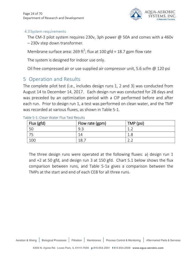
4.3 System requirements The CM-3 pilot system requires 230v, 3ph power @ 50A and comes with a 460v – 230v step down transformer.
Membrane surface area: 269 ft2; flux at 100 gfd = 18.7 gpm flow rate
The system is designed for indoor use only.
Oil free compressed air or use supplied air compressor unit, 5.6 scfm @ 120 psi
5 Operation and Results The complete pilot test (i.e., includes design runs 1, 2 and 3) was conducted from August 14 to December 14, 2017. Each design run was conducted for 28 days and was preceded by an optimization period with a CIP performed before and after each run. Prior to design run 1, a test was performed on clean water, and the TMP was recorded at various fluxes, as shown in Table 5-1.
Table 5-1: Clean Water Flux Test Results
Flux (gfd) Flow rate (gpm) TMP (psi) 50 9.3 1.2 75 14 1.8 100 18.7 2.2
The three design runs were operated at the following fluxes: a) design run 1 and +2 at 50 gfd, and design run 3 at 150 gfd. Chart 5.1 below shows the flux comparison between runs, and Table 5-1a gives a comparison between the TMPs at the start and end of each CEB for all three runs.

Page 25 of 70 Department of Research and Development
Chart 5.1: Flux Comparison Between Design Runs 1-3
Table 5-1a: TMP Comparison Between CEBs for Design Runs 1-3
Design Run 1 Design Run 2 Design Run 3 Average TMP After CEB 3.1 psi 2.3 psi 6.9 psi Average TMP Prior to Next CEB 11.7 psi 4.4 psi 12.0 psi Average TMP Rise Between CEBs 8.6 psi 2.1 psi 5.1 psi
5.1 CIP Results
A CIP was conducted at the end of each design run. The CIP recipe used for all three runs is as follows (more details in Appendix A):
• solutions of 1% citric acid and 3000 ppm of sodium hypochlorite were used independently for cleaning;
• The chemical solution was prepared at ambient temperature before recirculation.
• Each chemical was recirculated for 2 hours followed by 2 hours of soaking.
• The Acid CIP solution was heated to approximately 80 deg. F for design runs 1 and 2
0 20 40 60 80
100 120 140 160 180 200
0 500 1000 1500 2000 2500 3000 3500
gfd/
psi
28 day test period
Flux Comparison for Design Runs 1 -3
run1
run2
run3

Page 26 of 70 Department of Research and Development
• The Hypochlorite CIP solution was heated to approximately 80 degrees Farenheit for design runs 1 and 2.
Following each chemical, the unit was placed back into service at various fluxes and the TMPs were recorded and compared to verify that this cleaning regime was indeed removing all of the foulant material from the membrane. The following charts and tables show the results of these tests; note that source water – not clean water – was used for each of these tests, so the resultant TMPs are 33-36% higher than the Clean Water Flux Test Results recorded in Table 5-1.
5.1.1 Run 1 CIP results
Chart 5.1a: Run1 CIP Conducted Using TID Water
0 1 2 3 4 5 6 7 8 9
10
TMP bef TMP aft TMP bef TMP aft
Acid CIP Hypo CIP
psi
Run 1 CIP Conducted on 9/27/2017 at 50 gfd Flux
Run 1

Page 27 of 70 Department of Research and Development
5.1.2 Run 2 CIP results
Chart 5.1b: Run 2 CIP Conducted Using Reeder Reservoir Water
Table 5-2: Run 2 Post Acid CIP Results at Various Fluxes Using Reeder Reservoir Water
Flux (gfd) Flow rate (gpm) TMP (psi) 50 9.3 2.0 75 14 2.7 100 18.7 3.6 125 23.3 4.3
Table 5-3: Run 2 Post Hypo CIP Results at Various Fluxes Using Reeder Reservoir Water
Flux (gfd) Flow rate (gpm) TMP (psi) 50 9.3 1.6 75 14 2.4 100 18.7 3 125 23.3 3.9
0 1 2 3 4 5 6 7 8 9
10
TMP bef TMP aft TMP bef TMP aft
Acid CIP Hypo CIP
psi
Run 2 CIP Conducted on 10/31/2017 at 50 gfd Flux
Run 2

Page 28 of 70 Department of Research and Development
5.1.3 Run 3 CIP results
Chart 5.1c: Run 3 CIP Conducted Using Reeder Reservoir Water
Table 5-4: Run 3 Post Acid CIP Results at Various Fluxes on Reeder Reservoir Water
Flux (gfd) Flow rate (gpm) TMP (psi) 50 9.3 2 75 14 2.7 100 18.7 3.6 125 23.3 4.3 150 28 7.2
Table 5-5: Run 3 Post Hypo CIP Results at Various Fluxes on Reeder Reservoir Water
Flux (gfd) Flow rate (gpm) TMP (psi) 50 9.3 1.6 75 14 2.4 100 18.7 3 125 23.3 3.9 150 28 5.8
0 1 2 3 4 5 6 7 8 9
10
TMP bef TMP aft TMP bef TMP aft
Acid CIP Hypo CIP
psi
Run 3 CIP Conducted on 12/12/17 at 150 gfd Flux
Run 3

Page 29 of 70 Department of Research and Development
Chart 5.1d: Comparison of CIP Results for All Three Runs
Since there are no test results following the initial CIP (prior to run 1) – only a clean water test – the 1.4 psi TMP after the hypochlorite CIP following run 1 (shown as the blue bar on the right in Chart 5.1d above) must be compared to the 2.0 psi TMP baseline recorded during run 1. The CIP after run 1 actually lowered the TMP. Chart 5.1d also shows that the TMPs following runs 2 and 3 – both on Reeder Reservoir water – were exactly the same (1.6 psi), indicating that the CIPs were able to remove all of the foulant on the membrane.
5.2 Design run 1 Design run 1 was conducted from 08/30/17 to 9/27/17. This run was conducted to evaluate the ceramic membrane performance using water from the Talent Irrigation District (TID). The operational settings established during the optimization period prior to starting design run 1 are shown in Table 5-6 below.
0
1
2
3
4
5
6
7
8
TMP bef TMP aft TMP bef TMP aft
Acid CIP Hypo CIP
psi
CIP Results Comparing All Three Test Runs - All at 50 gfd Flux
Run 1
Run 2
Run 3

Page 30 of 70 Department of Research and Development
Table 5-6 Operating Conditions Established During Design Run 1
Parameter Value Flux 50 gfd Flow rate 9.3 gpm Filtration / Backwash (BW) cycle 45 minutes CEB cycle 1x /day CEB soak time 60 minutes Coagulant dose (ppm 50% ACH) 2 ppm to CM3 unit, starting 9/17/17
Feed water was fed into the CM3 unit’s mix tank and kept at a low tank volume (i.e., approximately 50 gallons). An overflow was installed on the tank to ensure this level was maintained. Coagulant at 8 ppm (as 50% ACH) was intended to be injected by the Owner into the raw feed supply at the start of the test run (common for all MFEMS), but it was later discovered during design run 2 that no ACH had been injected during run 1 or during run 2 prior to 10/11/2017. However, due to elevated TMP levels observed during run 1, , AASI began the injection of 2 ppm coagulant (as 50% ACH) into the CM-3 pilot mix tank to help control TMP levels; this can be observed in the data on Chart 5.2.1a.
Starting TMP value was 3.5 psi (at 50 gfd flux) with peaks (i.e., highest TMP value between backwash or CEB events) ranging from 10 psi to 20 psi (avg) at the end of the 45-minute BW cycle and baseline TMP 2-4 psi. After adding the 2 ppm ACH dose, TMP peaks were reduced to 10–15 psi with baseline (i.e., post-backwash) TMP between 2-3 psi, recovered after CEB events. The following charts, 5.2a and 5.2b, show the impact of adding the 2 ppm ACH dose. The general trend shown in chart 5.2a for TMP peaks is sharply upward with slope of 1.1 (roughly) whereas, with the 2 ppm ACH dose (refer to Chart 5.2b), the general trend for TMP peaks is moderately upward with slope of 0.13 (roughly).

Page 31 of 70 Department of Research and Development
Chart 5.2a: TMP Baseline - Peak Analysis with No ACH Dose
Chart 5.2b Baseline and Peak TMP Analysis with 2 ppm ACH Dose After 9/17/2017
Backwash events numbered 896 throughout the 28 day test which amounted to 11,827 gallons of backwash waste (this accounts for CEB waste volume as well). CEB events occurred 28 times (60 min total soak time / event) in total. Total filtrate volume (i.e., minus BW and CEB waste volumes) was 346,744 gallons. Total feed to system volume was 358,571 gallons. Total system recovery was 96.7 %.
y = 1.1054x - 47908 R² = 0.5678
0
5
10
15
20
25
30 4-
Sep
5-Se
p 6-
Sep
7-Se
p 8-
Sep
9-Se
p 10
-Sep
11
-Sep
12
-Sep
13
-Sep
14
-Sep
15
-Sep
16
-Sep
psi
Run 1 - No ACH Dose (08/30 to 9/17/17)
baseline
peak
Linear (baseline)
Linear (peak)
y = 0.1313x - 5685.2 R² = 0.0156 0
2
4
6
8
10
12
14
16
17-S
ep
18-S
ep
19-S
ep
20-S
ep
21-S
ep
22-S
ep
23-S
ep
24-S
ep
25-S
ep
26-S
ep
psi
Run 1 - With 2 ppm ACH Dose (after 9/17/17)
baseline
peak
Linear (baseline)
Linear (peak)

Page 32 of 70 Department of Research and Development
Total reject rate (i.e., as a percentage of feed, BW+ CEB waste volumes) was 3.3 %. Lastly, a CIP was performed prior to starting and directly after the 30 day test. The results from the CIP following this test run are shown in section 5.1 on chart 5.1a.
5.2.1 Data Charts for Design Run 1
Chart 5.2.1a: TMP Data for Design Run 1 on TID Water (psi)
Chart 5.2.1b: Flux and Flow Rate for Design Run 1
0
2
4
6
8
10
12
14
16
18
20
22
24
26
28
30
8/26/2017 0:00 8/31/2017 0:00 9/5/2017 0:00 9/10/2017 0:00 9/15/2017 0:00 9/20/2017 0:00 9/25/2017 0:00 9/30/2017 0:00
psi
TMP (psi) from Design Run 1 (08/30 to 09/27/2017)
E
A
B C
D
0
5
10
15
20
25
30
35
40
45
50
0
50
100
150
200
250
300
8/26/2017 0:00 8/31/2017 0:00 9/5/2017 0:00 9/10/2017 0:00 9/15/2017 0:00 9/20/2017 0:00 9/25/2017 0:00 9/30/2017 0:00
gpmgfd
Flux (gfd) and Flow Rate (gpm) from Design Run 1 (8/30 to 9/27/2017)
flux (gfd, primary axis)
Temp corrected flux (gfd @ 20 deg. C, primary axis)
Feed pump flow rate (gpm, secondary axis)
A
A Missing data due to data storage rollover (from 08/30 to 09/03/2017) B Downtime due to troubleshooting for (PDT) air leak ~10hours C CEB was ineffective here. This is indicative of a dosing problem (i.e., airlock or prime loss) D Corrected CEB (hypo) dosing pump problem. Seems to have been air locked E Started 2 ppm ACH supplement to feed at this point forward

Page 33 of 70 Department of Research and Development
Chart 5.2.1c: Permeability for Design Run 1 (gfd/psi)
Chart 5.2.1d: Feed Turbidity for Design Run 1 (NTU)*
*Note: the drop off from 9/22 to 9/27 is a period where feed turbidity readings reached maximum range (i.e., 100 NTU) on the turbidimeter – due to solids buildup in measurement chamber. This was cleaned at end of run (9/27/2017).
0
5
10
15
20
25
30
35
40
45
50
8/26/2017 0:00 8/31/2017 0:00 9/5/2017 0:00 9/10/2017 0:00 9/15/2017 0:00 9/20/2017 0:00 9/25/2017 0:00
gfd/
psi
Permeability (gfd/psi) from Design Run 1 (8/30 to 9/27/2017)
Permeability (gfd/psi)
Temperature Corrected Permeability (gfd/psi @ 20 deg. C, in shadow)
AB
C
D
E
0
20
40
60
80
100
8/26/2017 0:00 8/31/2017 0:00 9/5/2017 0:00 9/10/2017 0:00 9/15/2017 0:00 9/20/2017 0:00 9/25/2017 0:00 9/30/2017 0:00
NTU
Feed Turbidity (NTU) from Design Run 1 (8/30 to 9/27/2017)
Turbidity readings off scale (ie, >100NTU) due to solids buildup in measurement chamber)
Changed scale to show max range where turbidityreadings went off scale from 9/22 to 9/27)
Spiking due to vibrations from compressor pump mounted on skid
A
A Missing data due to data storage rollover (from 08/30 to 09/03/2017) B Downtime due to troubleshooting for (PDT) air leak ~10hours C CEB was ineffective here. This is indicative of a dosing problem (i.e., airlock or prime loss) D Corrected CEB (hypo) dosing pump problem. Seems to have been air locked E Started 2 ppm ACH supplement to feed at this point forward

Page 34 of 70 Department of Research and Development
Chart 5.2.1e: Filtrate Turbidity for Design Run 1 (NTU)
Chart 5.2.1f: Feed pH and Temperature for Design Run 1
0
1
2
3
4
5
6
8/26/2017 0:00 8/31/2017 0:00 9/5/2017 0:00 9/10/2017 0:00 9/15/2017 0:00 9/20/2017 0:00 9/25/2017 0:00
NTU
Filtrate turbidity (NTU) from Design Run 1 (8/30 to 9/27/2017)
Filtrate turbidity measurements were impacted by vibrations from the air compressor pump (which is also mounted on skid), causing spiking at levels greater than expected filtrate turbidity for this membrane. The filtrate turbidimeter was later relocated offskid to minimize the impact.
Changed scale to show max range where turbidityspiking event readings went off scale from 9/03 to 9/14)
A
0
1
2
3
4
5
6
7
8
9
10
0
5
10
15
20
25
30
8/26/2017 0:00 8/31/2017 0:00 9/5/2017 0:00 9/10/2017 0:00 9/15/2017 0:00 9/20/2017 0:00 9/25/2017 0:00 9/30/2017 0:00
pH
Degr
ees C
Feed Temperature (deg C) and pH from Design Run 1 (8/30 to 9/27/2017)
Feed Temperature (deg C, primary axis)
Raw water pH (secondary axis)
A

Page 35 of 70 Department of Research and Development
Chart 5.2.1g: CEB Results for Design Run 1
5.3 Design Run 2
Design run 2 was conducted from 10/03/17 to 10/31/17. This run was conducted to evaluate the ceramic membrane performance with a conservative flux using water from the Reeder Reservoir. The operational settings established during the optimization period prior to starting design run 2 are shown in Table 5-7.
Table 5-7 Operating Conditions Established During Design Run 2
Parameter Value Flux 50 gfd Flow rate 9.3 gpm Filtration / Backwash (BW) cycle 60 minutes* CEB cycle 1x /day** CEB soak time 60 minutes Coagulant dose (as 50% ACH) 8 ppm in common feed, started on 10/11
*Increased filtration /BW cycle time from 60 to 720 (12 hr) minutes on 10/23/17 to increase recovery **Decreased CEB frequency from 1x/day to 1x/week on 10/23/17
Pretreated feed water was fed into the CM3 unit’s mix tank in the same way as done for design run 1. However, the feed water source for design run 2 was changed to the Reeder Reservoir. On 10/11/17, it was discovered that the
0
5
10
15
20
25
30
psi
Run 1 CEB start and end TMP (psi) 9/03 to 9/27/2017
Start TMP
End TMP
Linear (Start TMP)
Linear (End TMP)

Page 36 of 70 Department of Research and Development
coagulant was not being injected into the raw feed supply; following this date, 8 ppm (as 50% ACH) was injected in the feed line common to all pilots.
Starting baseline TMP value was 1.8 psi (at 50 gfd flux). TMP peaks ranged from 2 – 12 psi. Backwash events numbered 496 throughout the 28 day test, which amounted to 6,547 gallons of backwash waste (this accounts for CEB waste volume as well). CEB events occurred 21 times (60 min total soak time / event) in total. Total filtrate volume (i.e., minus BW and CEB waste volumes) was 355,846 gallons. Total feed to system volume was 362,393 gallons. Total system recovery was 98.1%. Total reject rate was 1.8%. A CIP was conducted upon completion of this test run; the results are given in section 5.1.
5.2.1 Data Charts for Design Run 2
Chart 5.3.1a: TMP Data for Design Run 2 (psi)
Notes to Key Box: (B) - We noticed that Hypo CEB was not cleaning effectively as shown by baseline TMP (i.e., post backwash TMP) between (A) and (B) points on chart 5.3.1a. TMP was climbing and not returning close to baseline as expected. After increasing to 300 ppm (from 100), we found the post BW TMP returning close to baseline as shown directly after point (B) on chart 5.3.1a. We believe the dose can be further optimized.
0
2
4
6
8
10
12
14
16
18
20
22
24
26
28
30
10/2/2017 0:00 10/7/2017 0:00 10/12/2017 0:00 10/17/2017 0:00 10/22/2017 0:00 10/27/2017 0:00 11/1/2017 0:00
psi
TMP (psi) from Design Run 2 (10/3 to 10/31/2017)
F
A
B C
DE
(A) Test phase 2 start at 50 gfd flux (9.3 gpm flow rate). 60 min BW cycle, 1x/day CEB (B) Increased Hypochlorite CEB dose from 100 ppm to 300 ppm (C) Starting point at which 8 ppm ACH was injected to raw feed water (D) Increased flux to 75 gfd, directly after phone meeting with Keller. This was started at 10:30 am and
ended later in the same day at 6:30pm, where flux was returned to 50 gfd per Keller’s request. (E) System shutdown due to apparent program hang-up at time of a CEB event. Start at 9:20 am and ended
at 3:30pm (F) Increased filtration time (BW cycle) from 60 to 720 minutes and decreased CEB from 1x/day to 1x/week

Page 37 of 70 Department of Research and Development
(C) The 8 ppm dose was Owner fed/supplied as common to all MFEM systems. We did not add any supplemental coagulant during Run 2.
(D) During regular phone call with Bryan Phinney (Keller and Associates), it was discussed that since we started Run 2 expecting the Owner to inject the common 8 ppm ACH dose , and later discovered it hadn’t been dosed at all until 10/11/17, we would be permitted to increase flux to 75 gfd (i.e., from 50 gfd). It was increased on 10/12 at 10:30am. The driver for this request was the performance increase as shown on chart 5.2.1a from 10/11 – 10/31/17. Later the same day, I received a call from Bryan notifying that the flux change cannot occur and to revert back to the original starting flux of 50 gfd, which was promptly done on 10/12 at 8:20pm
(F) The changes made during this time period were done to decrease operating costs, in lieu of increasing flux, which was not permitted. Instead, we maximized operating conditions – i.e., increased filtration time / decreased BW frequency and decreased CEB frequency to cut waste and associated costs. The two changes (i.e., filtration time and CEB frequency) did not occur at the same time. A full day of data transpired before finding that decreasing CEB frequency from 1x/day to 1x/week was effective.
Chart 5.3.1b: Flow and Flux Data for Design Run 2* *Note: refer to key box notes from chart 5.3.1a
0
5
10
15
20
25
30
35
40
45
50
0
50
100
150
200
250
300
10/2/2017 0:00 10/7/2017 0:00 10/12/2017 0:00 10/17/2017 0:00 10/22/2017 0:00 10/27/2017 0:00 11/1/2017 0:00
gpm
gfd
Flow and Flux data from Design Run 2 (10/3 to 10/31/2017)
Flux (gfd, primary axis)
Temperature corrected flux (gfd/psi, primary axis)
Feed pump flow rate (gpm, secondary axis)
D
A

Page 38 of 70 Department of Research and Development
Chart 5.3.1c: Permeability Data for Design Run 2 (gfd/psi)* *Note: refer to key box notes from chart 5.3.1a
Chart 5.3.1d: Feed Turbidity Data for Design Run 2
0
5
10
15
20
25
30
35
40
45
50
10/2/2017 0:00 10/7/2017 0:00 10/12/2017 0:00 10/17/2017 0:00 10/22/2017 0:00 10/27/2017 0:00 11/1/2017 0:00
gfd/
psi
Permeability (gfd/psi) from Design Run 2 (10/3 to 10/31/2017)
Permeability (gfd/psi)
Temperature corrected Permeability (gfd/psi @20 deg. C, in shadow)A
B C
D E F
0
0.5
1
1.5
2
2.5
3
3.5
4
10/2/2017 0:00 10/7/2017 0:00 10/12/2017 0:00 10/17/2017 0:00 10/22/2017 0:00 10/27/2017 0:00 11/1/2017 0:00
NTU
Feed turbidity (NTU) from Design Run 2 (103 to 10/31/2017)
Spiking due to vibrations from compressor pump mounted on skid causing bubbling inmeasurement chamber

Page 39 of 70 Department of Research and Development
Chart 5.3.1e: Filtrate Turbidity Data for Design Run 2
Chart 5.3.1f: Feed Temperature and pH Data for Design Run 2
0
0.01
0.02
0.03
0.04
0.05
0.06
0.07
0.08
0.09
0.1
10/2/2017 0:00 10/7/2017 0:00 10/12/2017 0:00 10/17/2017 0:00 10/22/2017 0:00 10/27/2017 0:00 11/1/2017 0:00
NTU
Filtrate turbidity (NTU) from Design Run 2 (10/3 to 10/31/2017)
Excessive spiking due to vibration induced bubbling in turbidimeter unit - coming from filtrate water tank (as it is located on the same skid as compressor pump which causes the vibrations). A bubble trap was installed later which controlled the bubbling impacts
0
1
2
3
4
5
6
7
8
9
10
0
5
10
15
20
25
30
10/2/2017 0:00 10/7/2017 0:00 10/12/2017 0:00 10/17/2017 0:00 10/22/2017 0:00 10/27/2017 0:00 11/1/2017 0:00
pH
Degr
ees C
Feed Temperature and pH from Design Run 2 (10/3 to 10/31/2017)
Feed Temperature (deg. C, primary axis)
Feed water pH (secondary axis)

Page 40 of 70 Department of Research and Development
Chart 5.3.1g: CEB results for Design Run 2
5.4 Design run 3 Design run 3 was conducted from November 14 to December 12, 2017. Feed water from the Reeder Reservoir was fed into the CM3 unit mix tank and then pumped into the ceramic membrane system at a flow rate of 28 gpm (150 gfd). Operating conditions established during the optimization period for design run 3 are summarized below in Table 5-8.
Table 5-8 Operating Conditions Established During Design Run 3 Parameter Value Flux 150 gfd Flow rate 28 gpm Filtration / Backwash (BW) cycle 90 minutes CEB cycle 1x /3days CEB soak time 60 minutes Coagulant dose (as 50% ACH) 8 ppm in common feed
Starting TMP baseline was 4.9 psi, and ending TMP baseline was 8.3 psi. TMP baseline (i.e., Post backwash TMP) average rate of increase / day was 0.15 psi. TMP peaks ranged from 9.4–17 psi (peaks greater than 15 psi spiked briefly when coagulant feed was stopped from 11/25 to 11/27/2017). Total system recovery
0
5
10
15
20
25
30 4-
Oct
5-O
ct
6-O
ct
7-O
ct
8-O
ct
9-O
ct
10-O
ct
11-O
ct
12-O
ct
13-O
ct
14-O
ct
15-O
ct
16-O
ct
17-O
ct
18-O
ct
19-O
ct
20-O
ct
21-O
ct
22-O
ct
23-O
ct
psi
Run 2 CEB start and end TMP (psi) from 10/03 to 10/23/2017
Start TMP
End TMP
Linear (Start TMP)
Linear (End TMP)

Page 41 of 70 Department of Research and Development
was 99.5%. Total Feed flow was 1,076,740 gallons. Total waste volume (i.e., from BW and CEB events) was 5,913.6 gallons. Total filtrate volume (i.e., minus waste volume) was 1,070,826 gallons. Total reject rate was 0.5%. A CIP was performed after this run; the results are given in Tables 5-4 and 5-5.
5.4.1 Data charts for Design run 3
Chart 5.4.1a: TMP Data for Design Run 3 * *Note: The TMP range between backwashing and CEB is higher on this run due to the higher flux /feed flow rate, and longer filtration time (i.e., 90 minutes) and as a result, higher solids loading.
y = 0.1901x - 8178.3R² = 0.1861
0
5
10
15
20
25
30
11/11/2017 0:00 11/16/2017 0:00 11/21/2017 0:00 11/26/2017 0:00 12/1/2017 0:00 12/6/2017 0:00 12/11/2017 0:00 12/16/2017 0:00
psi
TMP (psi) data for Design run 3 from 11/14 to 12/12/2017
= CEB

Page 42 of 70 Department of Research and Development
Chart 5.4.1b: Flow and Flux Data for Design Run 3
Chart 5.4.1c: Permeability Data for Design Run 3 (gfd/psi)
0
5
10
15
20
25
30
35
40
45
50
0
50
100
150
200
250
300
11/11/2017 0:00 11/16/2017 0:00 11/21/2017 0:00 11/26/2017 0:00 12/1/2017 0:00 12/6/2017 0:00 12/11/2017 0:00 12/16/2017 0:00
gpm
gfd
Flow and Flux data chart for Design run 3 (11/14 to 12/12/17)
flux (gfd)
Temp Corr Flux (gfd)
Feed pump flow (gpm) -secondary axis
0
5
10
15
20
25
30
35
40
45
50
11/11/2017 0:00 11/16/2017 0:00 11/21/2017 0:00 11/26/2017 0:00 12/1/2017 0:00 12/6/2017 0:00 12/11/2017 0:00 12/16/2017 0:00
gfd/
psi
Permeability data chart for Design run 3 (11/14 to 12/12/17)
Permeability (gfd/psi)
Norm Perm (gfd/psi at 20 deg. C)

Page 43 of 70 Department of Research and Development
Chart 5.4.1d: Feed Turbidity Data for Design Run 3 (NTU)
Chart 5.4.1e: Filtrate Turbidity Data for Design Run 3 (NTU)
0
0.5
1
1.5
2
2.5
3
3.5
4
11/11/2017 0:00 11/16/2017 0:00 11/21/2017 0:00 11/26/2017 0:00 12/1/2017 0:00 12/6/2017 0:00 12/11/2017 0:00 12/16/2017 0:00
NTU
Feed turbidity (NTU) data chart for Design run 3 (11/14 to 12/12/17)
0
0.01
0.02
0.03
0.04
0.05
0.06
0.07
0.08
0.09
0.1
11/11/2017 0:00 11/16/2017 0:00 11/21/2017 0:00 11/26/2017 0:00 12/1/2017 0:00 12/6/2017 0:00 12/11/2017 0:00 12/16/2017 0:00
NTU
Filtrate turbidity (NTU) data chart for Design run 3 (11/14 to 12/12/17)

Page 44 of 70 Department of Research and Development
Chart 5.4.1f: Feed Temperature and pH Data for Design Run 3
Note: A PDT result of <1.0 psi drop over 10 minutes assures a 4-log removal of 3 micron sized particles.
Chart 5.4.1g: PDT Result Data for Design Run 3
0
1
2
3
4
5
6
7
8
9
10
0
5
10
15
20
25
30
11/11/2017 0:00 11/16/2017 0:00 11/21/2017 0:00 11/26/2017 0:00 12/1/2017 0:00 12/6/2017 0:00 12/11/2017 0:00 12/16/2017 0:00
pH
Deg.
CFeed Temperature and pH data chart for Design run 3 (11/14 to 12/12/17)
Feed Temp (deg C)
Feed pH (secondary axis)
0
1
2
3
4
5
6
-1
1
3
5
7
9
11
13
15
17
19
21
23
25
11/11/2017 0:00 11/16/2017 0:00 11/21/2017 0:00 11/26/2017 0:00 12/1/2017 0:00 12/6/2017 0:00 12/11/2017 0:00 12/16/2017 0:00
LRV
psi
PDT Result data chart for Design run 3 (11/14 to 12/12/17)
PDT decay
PDT_Filtrate Press PIR1_Begin (psi)
PDT_Feed press PIR2Begin (psi)
PDT Feed press PIR2 END (psi)
LRV (secondary axis)

Page 45 of 70 Department of Research and Development
Chart 5.4.1h: CEB Results Data for Design Run 3
6. Discussion AASI conducted three design run pilot tests at the City of Ashland, OR WTP from August to December 2017. Design run 1 was conducted on TID water source, whereas design runs 2 and 3 were conducted using water from the Reeder Reservoir. Feed water for part of design run 2 and all of design run 3 was pretreated with 8 ppm of coagulant (as 50% ACH), which was injected upstream of all three pilots. Based on data where coagulant feed was consistently dosed, the 8 ppm ACH permitted higher flux operation and with controlled TMP. Lower doses can/should be evaluated.
Design run 1 was a challenging run, with relatively high TOC and turbidity levels found in the TID water source. Feed TOC ranged from 2.4 to 2.9, and feed turbidity ranged from 5 to 20 NTU. By contrast, design run 2 - using the Reeder Reservoir as feed source - had about half the feed TOC levels (1.4 to 1.9 mg/l) and a fraction of the feed turbidity levels (ranging from 0.2 to 2 NTU). During design run 3, however, the Reeder Reservoir TOC level was nearly identical to that of the TID source (ranging from 2.2 to 2.9 mg/l), and the turbidity more than doubled that seen during run 2 (ranging from 0.6 to 3 NTU).
0
5
10
15
20
25
30
psi
Run3 CEB start and end TMP (psi) from 11/14 to 12/10/2017
Start TMP
End TMP
Linear (Start TMP)
Linear (End TMP)

Page 46 of 70 Department of Research and Development
Baseline TMP (i.e., post-backwash TMP) was maintained (average of 3 psi) throughout test run 1, providing a near zero TMP average rate increase / day. However, TMP peaks between CEB events spiked as high as 25 – 30 psi (between 9/14 – 9/16/2017). This may be due to higher feed TOC levels during this period with no coagulant addition. To mitigate more frequent TMP spiking, a dose of 2 ppm of coagulant (as 50% ACH) was injected into the CM3 unit’s mix tank on the evening of 9/16/2017. As seen on the TMP chart for design run 1, TMP became more stable soon after the 2 ppm ACH dose started. In general, water with high TOC requires well-controlled pretreatment for stable membrane operation. When operated without coagulant or with insufficient coagulant dosage, the results show faster membrane clogging will occur, requiring a more frequent CIP or more aggressive CEBs.
This run experienced some mechanical and PLC program issues. At the start, we lost data from 8/30 to 9/03/2017 due to data collection rollover. The data cache was full and, to make space for new data, erased previous data in the process. Next, the systems’ PDT was not functioning properly and required a PLC program change as well as repair of air leaks around mechanical seals. Also, CEB functionality was impaired at a couple points throughout the test (noted as point C on the TMP chart for design run 1). This problem was found to be a priming issue with the hypochlorite dosing pump. Last, for more than half of the test, filtrate turbidity was experiencing spiking beyond the expected maximum of 0.1 NTU. Turbidity spikes higher than 5 NTU were recorded until it was discovered that the turbidimeter unit was impacted by vibrations from the air compressor pump, which was mounted on the skid along with the turbidimeter. To correct the problem, the turbidimeter unit was relocated off-skid where it was isolated from any vibrations. This modification was made on 9/14/2017 and the resultant stable filtrate turbidity is shown on the filtrate turbidity chart, averaging around 0.015 NTU.
This run shows that despite some problems along the way, and with inconsistent pretreatment, baseline TMP was moderately stable at 50 gfd. The data suggests there is great potential for a higher flux with a controlled and optimally dosed coagulant – the 8 ppm of coagulant (as 50% ACH) injected by the Owner during the last part of run 2 and during run 3 may be higher than necessary. For run 2, when

Page 47 of 70 Department of Research and Development
8 ppm ACH was dosed, we saw a nearly flat TMP response at 50 gfd flux (i.e., from 10/11/17 to 10/31/17). For this flux, coagulant dose could be reduced, or alternatively, a higher flux with the 8 ppm ACH could be achieved, as shown in run 3 TMP data.
Design run 2 was planned as a moderate flux run using the Reeder Reservoir water source. For this run, we decided on a conservative flux of 50 gfd, since coagulant injection was inconsistently applied during this run. Later into the test run, when the coagulant injection was started (on 10/11/2017); we found the flux of 50 gfd to be too conservative and not challenging to the system. This can be seen on the TMP chart from 10/13 to 10/23/2017. To maximize the CM3 performance during this run, we increased the recovery by increasing the filtration / BW cycle time from 60 to 720 minutes. Also, CEB frequency was reduced from 1x/day to 1x/week. The change from 60 to 720 minutes increased percent recovery from 97% to 98.1%.
Starting baseline TMP was at 1.8 psi and ending baseline TMP was 2.19 psi. TMP spiked to 12 psi on 10/06/2017. This event appeared to be due to both no coagulant injection and a weak CEB (i.e., possibly due to pump prime loss). As a result, CEB hypochlorite dosage was increased from 100 to 300 ppm. Later, on 10/11/2017, 8 ppm 50% ACH coagulant was injected into the common feed stream. This change dramatically improved TMP performance and stability, as seen on the TMP data chart for design run 2. CEB frequency was decreased on 10/11/2017 as well – from 1x/day to 1x/week. This reduced the chemical consumption by roughly 30%. Whereas this run has shown TMP to be very stable (i.e., with consistent coagulation), the system was under-challenged. The evidence for this is seen in design run 3, as the system flux was pushed to 150 gfd. A more appropriate “conservative / moderate” flux for design run 2 should have been at least 100 gfd. Filtrate turbidity was recorded between 0 and 0.02 NTU, with average at 0.01 NTU. Permeability appears to have stabilized on 10/13/2017 from 29 to 22 gfd/psi in roughly 18 days.
Design run 3 was planned as the more aggressive flux test. This run also used the Reeder Reservoir water as its feed water source. Coagulant was injected from the start of this test at 8 ppm (as 50% ACH) into the common feed line. Flux was 150

Page 48 of 70 Department of Research and Development
gfd (28 gpm), which was an aggressive flux but with stable TMP. Starting baseline TMP was at 4.9 psi, and ending baseline TMP was 8.3 psi. TMP average rate of increase was 0.15 psi/day. There was a brief period from 11/25 to 11/27/2017 where the coagulant injection was stopped, this caused TMP spiking during this period as shown on the TMP chart. Later on 11/27/2017, coagulant injection was restarted and stable TMP quickly recovered. Permeability at the start of test was 39 gfd/psi and ended at 18 gfd/psi. Based on these results, a 30 day CIP would be recommended, but possibly could go to 60 days (more data would be necessary for more accuracy). Filtrate turbidity was measured below 0.02 NTU throughout the test, except for a brief period of spiking to 0.09 NTU between 1/21 and 1/23/2017. This was a result of the turbidimeter being bumped while doing work nearby. Thereafter, filtrate turbidity stabilized below 0.02 NTU with an average around 0.01 NTU. The PDT chart shows that all PDTs passed. Average decay rate was 0.28 psi /10 mins (i.e., well below the 0.99 psi threshold, where it would fail PDT (Refer to Appendix F). The maximum PDT decay was 0.39 psi, and the minimum PDT decay was 0.14 psi.
7. Conclusions In conclusion, the series of pilot tests revealed the following optimal operating conditions for the AASI ceramic membrane system under the given conditions and with two different feed water sources:
1) For TID water source • 50 gfd flux (Note: based on the data, we believe a higher flux can be
achieved on this water with consistent and optimal coagulant dosing) • CEB @ 1x/day, alternating between a) 1-2 pH for 20 minutes followed by
300 ppm NaOCl for 40 minutes, and b) 300 ppm NaOCl for 60 minutes • 45 minute Backwash / Filtration cycle • 30 day CIP (or longer – based on when 15 psi baseline TMP is reached,
which wasn’t reached during the test) • For this water, Sodium hypochlorite was found to be most effective at
cleaning during CIP and CEB
2) For Reeder Reservoir water source

Page 49 of 70 Department of Research and Development
• 50 gfd flux was the conservative flux. This flux performed very well for this water. Based on the data, we believe a higher conservative flux can perform very well with consistent and optimal coagulant dosing.
• 150 gfd flux was the aggressive flux. This flux performed very well for this water, even with a significantly higher feed TOC and turbidity than seen during the lower flux (design run 2). Based on the slow rate of TMP increase, we believe a higher aggressive flux could be used and still have runs longer than 30 days between CIPs.
• CEB @ 1x/3 days when at 150 gfd, whereas 1x/week can be achieved at the conservative flux. CEB was also alternated between a) 1-2 pH for 20 minutes followed by 300 ppm NaOCl for 40 minutes, and b) 300 ppm NaOCl for 60 minutes.
• 720 minute Backwash / Filtration cycle for the conservative flux; whereas 90 minutes Backwash / Filtration cycle for the aggressive flux was ideal.
• CIP cycle for conservative flux can, when extrapolated out, be up to 6 months. CIP cycle for the aggressive flux can be up to 2 months. This is an estimate as this wasn’t the focus of the testing. To provide a more accurate frequency would require a longer test period.
8. 30-Year Life Cycle Cost As noted in the Section 2: Summary, we recommend the full-scale system consist of (2) 12-row units with (10) modules per row, which will provide a total of 6,000 m2 (64,590 ft2) of membrane area. A summary of the system’s equipment is given in Appendix H.
Based on this approach, the 30-year life cycle costs are shown in Table 8-1. Power and chemical calculations that were used to determine these costs are given in Appendices I and J. Because the same membrane has been installed at over 175 drinking water installations beginning in 1998, with only one membrane element replaced during that time, it’s likely that the membrane will not require replacement during the 30-year life of the plant; therefore, no membrane replacement cost has been factored in.
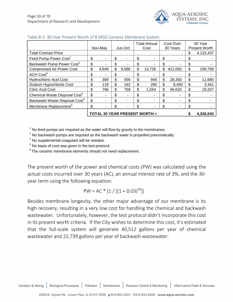
Page 50 of 70 Department of Research and Development
Table 8-1: 30-Year Present Worth of 8 MGD Ceramic Membrane System
Nov-May Jun-Oct Total Annual
Cost Cost Over 30 Years
30 Year Present Worth
Total Contract Price $ 4,122,437 Feed Pump Power Cost1 $ - $ - $ - $ - $ - Backwash Pump Power Cost2 $ - $ - $ - $ - $ - Compressed Air Power Cost $ 4,649 $ 9,086 $ 13,735 $ 412,050 $ 169,759 ACH Cost3 $ - $ - $ - $ - $ - Hydrochloric Acid Cost $ 389 $ 556 $ 945 $ 28,350 $ 11,680 Sodium Hypochlorite Cost $ 118 $ 162 $ 280 $ 8,400 $ 3,461 Citric Acid Cost $ 796 $ 758 $ 1,554 $ 46,620 $ 19,207 Chemical Waste Disposal Cost4 $ - $ - $ - $ - $ - Backwash Waste Disposal Cost4 $ - $ - $ - $ - $ - Membrane Replacement5 $ - $ - $ - $ - $ -
TOTAL 30 YEAR PRESENT WORTH = $ 4,326,543
1 No feed pumps are required as the water will flow by gravity to the membranes. 2 No backwash pumps are required as the backwash water is propelled pneumatically. 3 No supplemental coagulant will be needed.
4 No basis of cost was given in the test protocol. 5 The ceramic membrane elements should not need replacement.
The present worth of the power and chemical costs (PW) was calculated using the actual costs incurred over 30 years (AC), an annual interest rate of 3%, and the 30-year term using the following equation:
PW = AC * (1 / [(1 + 0.03)30])
Besides membrane longevity, the other major advantage of our membrane is its high recovery, resulting in a very low cost for handling the chemical and backwash wastewater. Unfortunately, however, the test protocol didn’t incorporate this cost in its present worth criteria. If the City wishes to determine this cost, it’s estimated that the full-scale system will generate 40,512 gallons per year of chemical wastewater and 22,739 gallons per year of backwash wastewater.

Page 51 of 70 Department of Research and Development
APPENDIX A: Clean-in-Place (CIP) Procedure As operation proceeds, foulant material will accumulate on the membrane surface which results in low permeability. To recover permeability, a Clean-in-Place (CIP) procedure is required. The following steps detail the procedure.
Clean-in-Place (CIP) Procedure
The objective of a CIP is to restore the baseline permeability of the membrane. The CIP procedure requires a 25 gallon tank, pump and tubing. The chemicals required are: 1% citric acid, 1000-3000 ppm sodium hypochlorite, (sodium bisulfite and sodium hydroxide, for neutralization, if required). The CIP process for pilot systems is prepared and operated manually, and includes two separate steps: (step 1) 1% citric acid CIP followed by (step 2) a 3000 ppm sodium hypochlorite CIP. For both steps, the chemical solution is mixed to 94 L of heated (80 to 100 deg. F, if necessary for deeper cleaning) filtrate in a tank. To make the 1% citric acid solution, measured 1.88L of 50% liquid citric acid and mix it to 94 liters of (heated, in cold temperatures) filtrate water. To make the 3000 ppm sodium hypochlorite solution, measure 2.25 liters of 12.5% sodium hypochlorite stock solution and mix it to 94 liters of (heated, in cold temperatures) filtrate water. A pump then transfers the solution into the membrane module feed side which is recirculated through to the top of the module and returns to the tank. Recirculation occurs for 2 hours in cross-flow mode. After 2 hours, the pump is stopped and a valve is closed on top of the module to allow for a 2 hour static soak for both the acid and hypochlorite, separately. Between each CIP step, a rinse cycle occurs for 10-30 minutes to ensure no chemical mixture occurs. At the end of the (step 2) hypochlorite CIP step, system operation proceeds to filtration mode where TMP can be observed / recorded and permeability is calculated. At the end of each CIP step, drain the module contents to the sewer.

Page 52 of 70 Department of Research and Development
The procedure: 1. Prepare the step 1 CIP acid solution to make 94 liters total volume. Use the tank
provided.
2. Set up pump and tubing. Connect tubing to bottom drain of CIP tank and opposite end to pump. Use smaller diameter tubing (with two small valves) in “tee” flow path, to connect to pump output and feed inlet of filter module. Refer to Figure A-1 for flow path to feed the module.
3. Stop process operation. 4. Drain BW tank: open AV3, AV7 and AV12 (low pressure air) to pressurize and push all
fluids to drain. Then close the same valves in reverse sequence (i.e., AV12, AV7, and AV3) when all water has evacuated from the BW tank. For valve locations, refer to the pilot’s Process and Instrumentation Drawing, #PID-001.
5. Drain Membrane module: open AV3, AV4, AV6 and AV12. 6. Knock on the module housing to know when the contents have drained (i.e., hear a
hollow sound). 7. Close all valves. Press “All Auto” button on lower right side of HMI screen in
“Operation” page 8. Release air pressure from module: Open ball valve “V34” on filtrate side of the
module. This valve is located on the left side of the module, labeled as filtrate sample port (about waist high). There should be black tubing connected to it. Place the tubing into a bucket and slowly open the valve by hand. The air should be released. Be careful.

Page 53 of 70 Department of Research and Development
9. Close valve. The module is now ready to be filled.
10. Open valve “V15” on top of module. This is a small, ½” or 3/8” valve with clear tubing connected to it. Place the end of this tube into a bucket.

Page 54 of 70 Department of Research and Development
11. Open the module feed sample port valve, “V20” (on right side of module, just below waist high). You should have the output tubing from the pump connected to here.
12. Open CIP tank valve (located at bottom of CIP tank). Tubing should be connected to here that feeds the suction end of the pump. There are two valves on this tubing. One should be between the pump and the CIP tank, whereas the other is between the pump and to drain.
13. Turn on the pump. The solution should now flow into the module feed side. When you see fluid come out from the top (via the clear tubing), allow some fluid to drain into the bucket (this is to displace any non CIP fluid). Relocate clear tubing (from top of module) to the CIP tank and allow the solution to circulate for 30 minutes to 1 hour (depending on fouling condition).
14. After the circulation period, stop pump, close valves “V15” on top of module (with
clear tubing) and “V20” (on bottom feed side of module). This is to allow a static soak for 4-8 for acid cleaning and 8-12 hours for hypochlorite cleaning.
15. At the end of the soak period, drain the module (repeat steps 4-8 above).
16. Prepare “rinse” step: go to “Process” page on the HMI. On the first page, find “Raw
Water Feed side”, which should be set to 60 seconds. Change this to 600 seconds.

Page 55 of 70 Department of Research and Development
This is to allow 10 minutes of rinse time to ensure minimal chemical mixing. 17. Go back to “Run/Stop” screen on HMI and press “On” button to start filtration
process. This will now fill the feed side for 10 minutes. Afterwards, press “Off” to stop the process.
18. Drain module again, repeat steps 4-8. Remember to release air pressure on the filtrate side valve (step 8).
19. The module is now ready for the second CIP step: Hypochlorite 20. Rinse the CIP tank thoroughly with clean water to remove all acid solution. Also be
sure to rinse the pump and tubing with clean water as well. 21. Add your hypochlorite solution to 94 L water into the CIP tank 22. Repeat steps 4 – 16 23. After completing CIP and final rinse step, the system is now ready to check for
permeability and/or for operator to conduct a clean water flux test.
Figure A-1: Recirculation Flow Path
To waste
94 liters of CIP chemical solution into CIP tank
Close valve when feeding module. Only open AV4 to drain module (step 5)
Filter module
V15
V20
AV4

Page 56 of 70 Department of Research and Development
APPENDIX B: Chemically-Enhanced Backwash (CEB) Procedure The CEB process for the CM-3 pilot system was operated automatically through HMI settings. For this pilot test, the CEB was conducted with various frequencies depending on the Design run. CEB frequency ranged from 1x/day, 1x/3 days, to 1x/ week for both acid (1-2 pH) and hypochlorite (100-300 ppm). In all three design runs, the CEBs alternated between a) a 20-minute soak at 1-2 pH followed by a 40-minute hypochlorite soak, and b) a 60-minute hypochlorite soak.
For the acid CEB, diluted hydrochloric (muriatic) acid was pumped into the backwash tank to make a 1-2 pH solution with filtrate. The CEB process then occurs automatically per the settings from the HMI panel. After the BW tank is filled with filtrate and acid solution, it is then pressurized to 20 psi. When the module is filled with the CEB solution, the pH is measured to ensure the correct dosage was achieved. After the 20-minute soak time, the system proceeds to normal backwash mode (i.e., pressurized to 72.5 psi). After finishing a backwash the system proceeds to the hypochlorite CEB (see below).
For the hypochlorite CEB, diluted sodium hypochlorite was pumped into the backwash tank to make a 100-300 ppm concentration with filtrate. The CEB process then occurs automatically per the settings from the HMI panel. After the BW tank is filled with filtrate and sodium hypochlorite solution, it is then pressurized to 20 psi. When the module is filled with the CEB solution, we measured pH and free chlorine to ensure the correct dosages were achieved. After 40 minutes soak time, the system proceeds to normal backwash mode (i.e., pressurized to 72.5 psi). After finishing a backwash the system proceeds to filtration mode.
The waste from the CEB process is discharged to the BW waste collection tank (on the skid), where it can be neutralized or simply drained out (as it was done during the pilot test at Ashland).
APPENDIX C: Integrity Test Procedure Membrane integrity was monitored daily to ensure an integral barrier is consistently provided by the membrane surface. Pressure Decay Testing (PDT) is applied as the direct integrity testing method. The process: After backwashing, compressed air enters the filtrate side of the membrane module. After all water is purged by pressurized air, pressure drop is monitored over 10 minutes from an applied air pressure of 20 psi. Results less than 1 psi drop over 10 minutes assures a 4-log removal of 3 micron sized particles.
Procedure:
1) After backwashing, Stop system 2) Adjust AR2 regulator valve to 20 psi 3) Pressurize the filtrate side by opening AV11, AV3, and AV4 4) Ensure that no more water is evacuating from AV4 5) Close AV4, AV3 and AV11 6) Record start pressure, PT2 (filtrate pressure) 7) Set timer to 10 minutes 8) Record end pressure after 10 minutes has expired, PT2 (filtrate pressure)

Page 57 of 70 Department of Research and Development
APPENDIX D: Certifications • NSF/ANSI 61 certified: for 1 element and 12 element modules. 1 element to minimum flow of
10,000 L /day. 12 modules to min of 120,000 L/day • California Department of Public Health (CDPH)
Flux 175gfd, LRV4 Cryptosporidium, LRV1 Virus • CDPH Title 22 for wastewater treatment • Colorado Department of Public Health and Environment
APPENDIX E: Instrumentation Calibrations 1. Turbidimeters
a. Feed (Hach ultraturb): via Hach SC1000 controller i. Hach StablCal method, 20NTU standard solution
ii. Time and date of calibration: 08/24/2017 @ 09:31 iii. Value: 20 NTU iv. Gain: 1.61
b. Filtrate (Hach Ultraturb): via Hach SC1000 controller
i. Hach StablCal method, 809.0 +/- 10.0 mNTU Standard solution (lot#A6242, exp. Aug. 2018)
ii. Time and date of Calibration: 08/24/2017 @ 10:11:26 iii. Value: 0.809mNTU iv. Gain: 0.98
2. pH probe: via Hach SC1000 controller
a. 2 point Calibration to pH7 and pH 10 b. Time and date of calibration: 08/30/2017 @ 7am

Page 58 of 70 Department of Research and Development
APPENDIX F: PDT results and LRV calculations Membrane integrity was monitored to ensure an integral barrier was consistently provided by the membrane surface. Pressure Decay Testing (PDT) was applied as the direct integrity testing method.
The process: After backwashing, compressed air enters the filtrate side of the membrane module. After all water is purged by pressurized air, the pressure drop is monitored over 10 minutes from an applied air pressure of 20 psi. Results less than 1 psi drop over 10 minutes assures a 4-log removal of 3 micron sized particles.
Pressure proof and airtight inspection conditions (per manufacturing facility, NGK)
a. Sub-module (without membrane) i. Water to 0.75 MPa (108.77psi) / 30 minutes
b. Housing (with membrane) i. Air to 0.12 MPa (17.4psi) / 1 min
c. Sub-module (with membrane) i. Water to 0.5 MPa (72.5psi) / 30 minutes
LRV Challenge Test
Testing was conducted by MWH to establish and confirm the 4-log Cryptosporidium removal ability of the AASI / MWR (NGK) ceramic membrane (all virus challenge tests were conducted without pretreatment using coagulant in order to conservatively evaluate the virus rejection ability of the ceramic membrane, alone) by the calculation method, as specified in the Long-Term 2 Enhanced Surface Water Treatment Rule (LT2ESWTR) and Environmental Protection Agency (EPA) Membrane Guidance Manual. Results successfully demonstrated that the AASI / MWR (NGK) ceramic membrane could reliably achieve at least 4-log removal for Cryptosporidium (without coagulant) based on the DIT.
LRV Test objectives:
a) Giardia Removal: Demonstrate a minimum of 2-log removal of Giardia sized particles (e.g., 5-15 µm)
b) Cryptosporidium Removal: Demonstrate removal of Cryptosporidium sized particles (e.g., 2-5 µm).
c) Virus Removal: Demonstrate a minimum 1-log removal d) Operations Reliability: Develop data for demonstrating the reliability of various
membrane filtration technologies e) Quality Control: Document a procedure for quality assurance and quality control
sufficient to ensure the integrity of the data collection and process.

Page 59 of 70 Department of Research and Development
Challenge test results and calculations
Testing Approach
NGK pressure-driven ceramic membrane pilot unit is operated in a deposition (i.e., dead-end) mode hydraulic configuration. A pressure decay test with an initial pressure of 20 psi was applied to the pilot unit. The operating parameters are listed in Table 5.1 of the MWH report (2005) and detailed in the “Sample Calculation” section below. With the DIT parameters established, the removal of Cryptosporidium was calculated and compared using the following models:
• Hagan-Poiseuille model: Flat sheet / hollow fiber module, laminar flow through the breach.
• Orifice model: Flat sheet module, turbulent flow through the breach.
Main skid calculations (these were test conditions used to determine LRV as conducted by third party testing organization, MWH)
Assumptions:
Operational parameters
• The design capacity of the pilot membrane unit is 36.6 gpm.
• The design flux of the pilot membrane unit is 200 gfd.
• The maximum anticipated water temperature is 77 oF (25 oC).
• The minimum anticipated water temperature is 41 oF (5 oC).
• The maximum anticipated backpressure (BPmax) that might be exerted on the units during direct integrity testing is 78 inches of water.
• The backpressure measured prior to the most recent pressure decay test was 78 inches of water.
• The filtrate flow measured prior to the most recent pressure decay test was 36.6 gpm.
Direct integrity test parameters
• The volume of pressurized piping during the test is 22 L.
• The initial applied test pressure of most recent pressure decay test is 20 psi.
• The duration of the pressure decay test is 10 minutes.
• Baseline (i.e., diffusive) decay is negligible over the duration of the test.

Page 60 of 70 Department of Research and Development
• The smallest verifiable rate of pressure decay under known compromised conditions is 0.10 psi/min.
• The most recent pressure decay test yielded a result of less than 0.10 psi/min.
• The temperature of both the water and the applied air were 74 oF (23 oC) during the most recent pressure decay tests.
Unit and membrane characteristics
• The maximum operating TMP is 55 psi.
• The pore shape correction factor (κ) for the membrane material was not determined experimentally, and thus a conservative value of 1 is assumed.
• The liquid-membrane contact angle (θ) was not determined experimentally, and thus a conservative value of 0 is assumed.
Calculate:
1. The minimum direct integrity test pressure commensurate with the required resolution of 3 µm for the removal of Cryptosporidium
2. The sensitivity of the direct integrity test
3. The UCL (Upper Control Limit) for the system to achieve a minimum removal of 4 log
4. The LRV verified by the most recent direct integrity test
Solution:
1. Calculate the Minimum Direct Integrity Test Pressure (Ptest) Commensurate with the Required Resolution of 3 µm for the Removal of Cryptosporidium
Ptest = (0.193 • κ • σ • cosθ) + BPmax Equation 4.1
κ = 1 most conservative value (from given information)
σ = surface tension at the air-liquid interface = 74.9 dynes/cm (the surface tension of water at 5 oC)
θ = 0o most conservative value from given information)
BPmax = 78 inches (of water column) from given information
Ptest=��0.193𝑝𝑠𝑖 ∙ 𝑐𝑚𝑑𝑦𝑛𝑒
� ∗ 1.0 ∙ 74.9 �𝑑𝑦𝑛𝑒𝑠𝑐𝑚
� ∙ cos(0°)� + �78𝑖𝑛𝑐ℎ𝑒𝑠∙𝐻2𝑂27.7𝑖𝑛𝑐ℎ𝑒𝑠∙𝐻2𝑂
/𝑝𝑠𝑖�

Page 61 of 70 Department of Research and Development
∴Ptest=17.3psi
The pressure calculated above is the lowest permissible initial pressure to apply for the proper test resolution, assuming the minimum anticipated temperature is 5oC. Table 7-1 lists the Ptest for required resolution at different minimum anticipated temperatures.
Table F-1: Required Testing Pressure for Proper Resolution at Different Temperatures Minimum anticipated temperature (oC) Ptest (psi) 2 17.4 5 17.3 10 17.1 15 17.0
In the most recent integrity test, since the applied test pressure was 20 psi, the resolution requirement of the LT2ESWTR is satisfied.
2. Calculate the Sensitivity of the Direct Integrity Test
LRVDIT=𝑙𝑜𝑔 �𝑄𝑝∙𝐴𝐿𝐶𝑅∙𝑃𝑎𝑡𝑚∆𝑃𝑡𝑒𝑠𝑡∙𝑉𝑠𝑦𝑠∙𝑉𝐶𝐹
� Equation 4.9
Qp = permeate flow = 36.6 gpm (design capacity filtrate flow per membrane)
Patm = atmospheric pressure = 14.7 psi (atmospheric pressure at sea level)
∆Ptest = change in test pressure = 0.10 psi/min (smallest verifiable decay rate)
Vsys = system volume = 22 L (from given information)
VCF = volumetric concentration factor = 1 (standard for deposition mode {i.e. dead-end filtration] configuration)
ALCR = air-liquid conversion ratio = To be determined
First, Hagan-Poiseuille flow model is used to calculate ALCR. This model is commonly applied to laminar flow breach condition in flat sheet or hollow fiber membrane filtration systems.

Page 62 of 70 Department of Research and Development
ALCR=527∙∆𝑃𝑒𝑓𝑓∙(175−2.71∙𝑇+0.0137∙𝑇2
𝑇𝑀𝑃∙(460+𝑇)
Equation C.15
TMP = 55 psi maximum TMP
T = 77 oF maximum temperature
∆Peff = effective integrity test pressure = To be determined
∆𝑃𝑒𝑓𝑓 = [(𝑃𝑡𝑒𝑠𝑡 − 𝐵𝑃)] ∗ �(𝑃𝑡𝑒𝑠𝑡 + 𝑃𝑎𝑡𝑚) + (𝐵𝑃 + 𝑃𝑎𝑡𝑚)
2 ∙ (𝐵𝑃 + 𝑃𝑎𝑡𝑚)� ∗ �
(𝐵𝑃 + 𝑃𝑎𝑡𝑚)𝑃𝑎𝑡𝑚
�
Equation C.12
P test = 20 psi initial test pressure
Patm = 14.7 psi atmospheric pressure at sea level
BP = 78 inches (of water column) from given information
Substituting values into Equation C.12 yields ∆Peff = 30.5 psi
The ALCR can be calculated follows:
𝐴𝐿𝐶𝑅 =527 ∙ 30.5𝑝𝑠𝑖 ∙ (175 − 2.71 ∙ 0.0137 ∙ 772)
55𝑝𝑠𝑖 ∙ (460℉ + 77℉)
∴ALCR =25.9
Substituting values into Equation 4.9 for sensitivity:
𝐿𝑅𝑉𝐷𝐼𝑇 = log �(36.6𝑔𝑝𝑚 ∙ 3.785 𝐿
𝑔𝑎𝑙) ∙ 25.9 ∙ (14.7𝑝𝑠𝑖)
0.1 𝑝𝑠𝑖𝑚𝑖𝑛 ∙ 22𝐿 ∙ 1
�
∴ 𝐿𝑅𝑉𝐷𝐼𝑇 = 4.4

Page 63 of 70 Department of Research and Development
Moreover, if a breach is specified as turbulence flow, Orifice flow model is used for the flat sheet system. This generates an even more conservative value of ALCR, which is shown as follows:
Equation C.9
𝐴𝐿𝐶𝑅 = 170 ∙ 𝑌 ∙ �(𝑃𝑡𝑒𝑠𝑡 − 𝐵𝑃) ∙ (𝑃𝑡𝑒𝑠𝑡 + 𝑃𝑎𝑡𝑚)
(460 + 𝑇) ∙ 𝑇𝑀𝑃
TMP = 55 psi maximum TMP
T = 77 oF maximum temperature
Ptest = 20 psi initial test pressure for Run-1
Patm = 14.7 psi atmospheric pressure
BP = 78 inches (of water column) from given information
Y = net expansion factor = To be determined
Equation C.10
𝑌 = 1 − �0.293 ∗ (1 − 𝐵𝑃+𝑃𝑎𝑡𝑚𝑃𝑡𝑒𝑠𝑡+𝑃𝑎𝑡𝑚
)�
Substituting values into Equation C.10 yields Y = 0.85
The ALCR can be calculated follows:
𝐴𝐿𝐶𝑅 = 170 ∙ 0.85 ∙�
(20𝑝𝑠𝑖 − 78𝑖𝑛𝑐ℎ𝑒𝑠 ∙ 𝐻2𝑂
27.7 𝑖𝑛𝑐ℎ𝑒𝑠 ∙ 𝐻2𝑂𝑝𝑠𝑖
) ∙ (20𝑝𝑠𝑖 + 14.7𝑝𝑠𝑖)
(460℉ + 77℉) ∙ 55𝑝𝑠𝑖
∴ 𝐴𝐿𝐶𝑅 = 20.6

Page 64 of 70 Department of Research and Development
3. Substituting values into Equation 4.9 for sensitivity:
𝐿𝑅𝑉𝐷𝐼𝑇 = log �(36.6𝑔𝑝𝑚 ∙ 3.785 𝐿
𝑔𝑎𝑙) ∙ 20.6 ∙ (14.7𝑝𝑠𝑖)
0.1 𝑝𝑠𝑖𝑚𝑖𝑛 ∙ 22𝐿 ∙ 1
�
∴ 𝐿𝑅𝑉𝐷𝐼𝑇 = 4.3
Therefore, at an initial test pressure of 20 psi, the maximum removal value that this membrane filtration system is capable of verifying is 4.4 log using Hagan-Poiseuille model and 4.3 log using Orifice model.
4. Calculate the Upper Control Limit (UCL) For This System
𝑈𝐶𝐿 =𝑄𝑝 ∙ 𝐴𝐿𝐶𝑅 ∙ 𝑃𝑎𝑡𝑚10𝐿𝑅𝐶 ∙ 𝑉𝑠𝑦𝑠 ∙ 𝑉𝐶𝐹
Equation 4.17
Qp = 36.6 gpm design capacity filtrate flow
ALCR = 25.9 using Hagan-Poiseuille mode
ALCR = 20.6 using Orifice model as determined in part 2, above
Patm = 14.7 psi atmospheric pressure at sea level
Vsys = 22 L from given information
LRC = log removal credit = 4 to achieve a minimum removal value of 4 log.
VCF = 1 standard for deposition mode (i.e. dead-end filtration) configuration
𝑈𝐶𝐿𝐻𝑎𝑔𝑎𝑛−𝑃𝑜𝑖𝑠 =(36.6𝑔𝑝𝑚 ∙ 3.785 𝐿
𝑔𝑎𝑙) ∙ 25.9 ∙ 14.7𝑝𝑠𝑖
104 ∙ 22𝐿 ∙ 1 ∙= 0.26𝑝𝑠𝑖/𝑚𝑖𝑛

Page 65 of 70 Department of Research and Development
𝑈𝐶𝐿𝑜𝑟𝑖𝑓𝑖𝑐𝑒 =(36.6𝑔𝑝𝑚 ∙ 3.785 𝐿
𝑔𝑎𝑙) ∙ 20.6 ∙ 14.7𝑝𝑠𝑖
104 ∙ 22𝐿 ∙ 1 ∙= 0.20𝑝𝑠𝑖/𝑚𝑖𝑛
Therefore, to demonstrate a LRV greater than 4, the pressure decay rate from the integrity test should be less than 0.26 psi/min according to the Hagan-Poiseuille model, and less than 0.20 psi/min according to the Orifice model.
5. Calculate The LRV Verified By The Most Recent Integrity Test.
Equation 4.9 can be used to determine the LRV verified by the most recent integrity test by applying values for the variables specific to the test events.
For the most recent integrity test at an initial testing pressure of 20 psi, the measured test decay rate is less than the smallest verifiable decay rate (0.10 psi/min). Therefore, the membrane unit demonstrates a removal value of 4.4 log using Hagan-Poiseuille model and 4.3 log using Orifice model.
Integrity Test Conclusions
The following conclusions can be made from the testing:
Table F-2 summarizes results from the direct integrity test. NGK established 20 psi as the standard applied pressure for pressure decay DITs. The high mechanic strength of ceramic membrane allows the use of higher pressure (20 psi) with the pressure decay testing, providing the benefit of demonstrating higher LRV.
Table F-2: Summary of Testing Result for main skid Ptest (psi) Model Module and
Defect Flow Sensitivity of DIT (LRVmax)
Verified LRV by DIT
20
Hagan-Poiseuille Flat sheet/ hollow fiber laminar
4.4 4.4
Orifice Flat sheet/ turbulent
4.3 4.3
It is important to note that Table F-2 presents conservative values of LRV since the most conservative membrane parameters are used in the calculation. For example, the maximum rated TMP of 55 psi (Colorado Department of Human Services testing condition) was used although the manufacturer

Page 66 of 70 Department of Research and Development
typically suggests operating the ceramic membrane up to 29 psi, under normal operating conditions. As 55 psi generates a lower LRV (4.4-log compared to 4.7-log at 29 psi using the Hagan-Poiseuille model), it is chosen as a more conservative value in the calculation. Moreover, a conservative value is assumed for the pore shape correction factor (κ) and the liquid-membrane contact angle (θ) as they were not determined experimentally.
Table F-3 shows the UCL (Upper Control Limit) values under different conditions to provide a minimum 4-log Cryptosporidium removal. Based on the calculation, the allowable pressure decay rate should be less than 0.20 psi/min to demonstrate a minimum removal of 4-log, when a DIT is performed at 20 psi. The manufacturer establishes 0.10 psi/min as their quality control release value (QCRV), which is an even more conservative requirement to ensure that LRV4 can be achieved.
Table F-3: Projection of LRV at Different Pressure Decay Rates Ptest (psi) Model ∆Ptest (psi/min) LRV UCL for LRV
greater than 4 (psi/min)
20
Hagan-Poiseuille
0.1 4.4 0.26 0.2 4.1
0.3 3.9 Orifice
0.1 4.3 0.2 0.2 4.0
0.3 3.8

Page 67 of 70 Department of Research and Development
APPENDIX G: Chemicals used during testing 1) Aluminum Chlorohydrate (ACH): 50% stock. 2 ppm to CM-3 influent during design run 1 from
Sept 17-27, 8 ppm to common raw water during design run 2 from Oct 12-31 and during all of design run 3
2) Hydrochloric (Muriatic) Acid: 32% (20 Bé) stock. To 1-2 pH for CEB. 3) Citric Acid: 50% stock. 1% concentration for CIP 4) Sodium Hypochlorite: 12.5% stock. 100-300 ppm concentration for CEB / 3000 ppm
concentration for CIP Chemical consumption for all three Design runs A) CEB chemical consumption (28 CEBs for design run 1; 21 CEBs for design run 2; 9 CEBs for
design run 3; 58 total CEBs )
1) Muriatic acid: consumption = 1.6 L / CEB; total = 93 L 2) 100-300ppm (0.01-0.03%) Sodium Hypochlorite: consumption is 0.12 L / CEB; total = 7 L
B) CIP chemical consumption (4 CIPs were performed throughout the three pilot tests)
1) 1% Citric Acid = 1.88L / 94L water (per CIP) = 7.52 L total consumed 2) 3000ppm Sodium Hypochlorite = 2.25 L / 94L water (per CIP) = 9 L total consumed
Note: All Chemicals were provided by the City of Ashland, OR

Page 68 of 70 Department of Research and Development
APPENDIX H: Equipment Summary for Full-Scale System

Equipment Summary
Compressed Air System
1 Valve Actuation Compressed Air System(s) will be provided as follows:
- (2) compressor pumps rated for 15 hp each pump with a 240-gallon receiver tank, 2 after coolers, alternating
control panel, and wide range pressure switches.
- (1) Coalescing, oil removing filter
- (1) Set of 4 machine vibration isolators
- (1) Adjustable pressure regulator
- (1) Air dryer
Membranes
240 Membrane Modules, each consisting of:
- 25 square meter ceramic membrane modules encased in 304 stainless steel housing.
24 Membrane Module Rack(s), each consisting of:
- Carbon steel structural framework, painted for corrosion protection.
- Piping within the membrane system skid, required for interconnection of skid mounted membrane system
components. Piping will be schedule 40 PVC, socket welded or threaded. Air piping will be stainless steel tubing
and schedule 10 stainless steel piping.
- Wiring of valves and instruments to skid panel.
- 1/2" full port, three piece, stainless steel body ball valve(s), grooved end connections with single phase electric
actuator(s). Valve / actuator combination shall be manufactured by TCI / Nibco or equal.
- 1" full port, three piece, stainless steel body ball valve(s), grooved end connections with single phase electric
actuator(s). Valve / actuator combination shall be manufactured by TCI / Nibco or equal.
- 2.5 inch pneumatically operated wafer style butterfly valve(s).
- 3 inch pneumatically operated wafer style butterfly valve(s).
- 1.5" full port, three piece, stainless steel body ball valve(s), grooved end connections with single phase electric
actuator(s). Valve / actuator combination shall be manufactured by TCI / Nibco or equal.
- 4 inch pneumatically operated wafer style butterfly valve(s).
- 8 inch pneumatically operated wafer style butterfly valve(s).
- 12 inch pneumatically operated wafer style butterfly valve(s).
- 1/2" stainless steel manual ball valves.
- 1.5" stainless steel check valve.
2 Remote I/O Panel(s) consisting of:
- NEMA 4X fiberglass enclosure(s).
- Fuses and fuse blocks.
- GFI convenience outlet(s).
- Control relay(s).
- Selector switch(es).
- Indicating pilot light(s).
- Ethernet switch(es).
- Power supply(ies).
- Terminal blocks.
- Ethernet adapter module(s).
- Input card(s).
- Output module(s).
- Analog output card(s).
- Terminal base(s).
- UL label(s).
- Disconnect switch(es).
1 Control Panel(s) consisting of:
- NEMA 12 panel enclosure suitable for indoor installation and constructed of painted steel.
03/26/2018 7:30:24AM Page 1 of 3Aqua-Aerobic Systems, Inc CONFIDENTIAL
ASHLAND WWTP OR / Design#: 151566

- Fuses and fuse blocks.
- GFI convenience outlet(s).
- Control relay(s).
- Selector switch(es).
- Indicating pilot light(s).
- Ethernet switch(es).
- Hubbell Cat 6 Ethernet Cable.
- Power supply(ies).
- Terminal blocks.
- Allen Bradley 1769-L33ER Compactlogix integral programmable controller.
- Compactflash.
- End cap(s).
- Power supply(s).
- Input card(s)
- Relay output(s).
- Analog input(s).
- Analog output(s).
- Panelview plus 6 1250 operator interface(s).
- UL label(s).
1 CIP System(s) will be provided as follows:
- 500-gallon polyethylene tank.
- (2) Centrifugal pump with 1.5 HP, 3 ph. motor.
- 1/2" full port, three piece, stainless steel body ball valve(s), grooved end connections with single phase electric
actuator(s). Valve / actuator combination shall be manufactured by TCI / Nibco or equal.
- 1" full port, three piece, stainless steel body ball valve(s), grooved end connections with single phase electric
actuator(s). Valve / actuator combination shall be manufactured by TCI / Nibco or equal.
- 1 1/2" full port, three piece, stainless steel body ball valve(s), grooved end connections with single phase electric
actuator(s). Valve / actuator combination shall be manufactured by TCI / Nibco or equal.
- 3" manual butterfly valve(s).
- pH/ORP sensor(s).
- Pressure transducer(s).
- Temperature transmitter(s).
- Hach CL17 total chlorine process analyzer(s).
2 Strainer(s) will be provided as follows:
- 18 inch automatic backwashable strainer with NSF-approved epoxy lining and 60 mesh 304 stainless steel screen.
Membrane Accessories
2 Common Skid Valves and Instrumentation, including the folllowing:
- 1/2" full port, three piece, stainless steel body ball valve(s), grooved end connections with single phase electric
actuator(s). Valve / actuator combination shall be manufactured by TCI / Nibco or equal.
- 1" full port, three piece, stainless steel body ball valve(s), grooved end connections with single phase electric
actuator(s). Valve / actuator combination shall be manufactured by TCI / Nibco or equal.
- 2.5 inch pneumatically operated wafer style butterfly valve(s).
- 3 inch pneumatically operated wafer style butterfly valve(s).
- 1/4" Threaded bronze ball valve.
- 1/2" stainless steel manual ball valves.
- 3/4" globe valve.
- 1" stainless steel manual ball valves.
- 1.5" stainless steel manual ball valves.
- 2.5" manual butterfly valve(s).
- 3" manual butterfly valve(s).
- 3" Magnetic flow meter(s).
- 8" Magnetic flow meter(s).
- 3/4" check valve.
- 1.5" check valve(s).
- 2.5" check valve(s).
- Pressure control valves.
03/26/2018 7:30:24AM Page 2 of 3Aqua-Aerobic Systems, Inc CONFIDENTIAL
ASHLAND WWTP OR / Design#: 151566

- 1.5" pressure control valve.
- 1/2" air pressure regulator.
- Pressure transducer(s).
- Air release valve.
- Pressure switches.
- Level transmitter.
2 Backwash System Tank(s) consisting of:
- Painted carbon steel backwash water tank(s).
- Painted steel air receiver tank(s).
Permeate Discharge Components
2 Turbidity Meter Assembly(ies) consisting of:
- Turbidity sensor(s).
- Hach SC200 controller and display module(s).
- Calibration start-up kit(s).
- Turbidity mounting plate(s).
Chemical Feed Systems
3 Chemical Feed Systems for hydrochloric acid, sodium hypochlorite, and citric acid, each system consisting of the following:
- UHMW backing panel(s).
- Calibration columns.
- Chemical feed pumps.
- Pressure relief valves.
- GFI outlet(s).
- Ball valves.
- 316 stainless steel shelf weldments.
- Polypropylene utility trays.
03/26/2018 7:30:24AM Page 3 of 3Aqua-Aerobic Systems, Inc CONFIDENTIAL
ASHLAND WWTP OR / Design#: 151566

Page 69 of 70 Department of Research and Development
APPENDIX I: Compressed Air Calculations for Full-Scale System

Compressor Calculations for the 7 Winter Months
Valves Feed Valves (Top and Bottom) Filtrate Valves Backwash Inlet Valves
Drain Valves (Top and Bottom)
Row Isolation Valves
Backwash Pump
Discharge Valves
Cycles per hour 0.28 0.28 0.28 0.28 0.28 0.28Total Qty 4 26 96 0 48 48Valve Selected (same size as pipe) 2.5 3 4 6 8 12
(N=1.25 above catalog values) Double Acting Actuators/ Reduced Disc Dia Valves (Fail in Position)Actuator (N=1.25 above catalog torque req'd) 92-0630 92-0830 92-0830 92-0830 92-1180 92-1270Basic Size Number 63 83 83 83 118 127 Backwash Compressor CalculationsAir req'd for full forward stroke (in3) 9.6 24.8 24.8 24.8 73.8 96.7 32 L/m2 @ 14.7 psia requiredAir req'd for full return stroke (in3) 13.4 32.6 32.6 32.6 95.5 130.8 17.9166667 min fill timeHourly Air Requirement (in3) 26 416 1538 0 2268 3047 447 L/min @ 14.7 psia totalTotal Air Requirement(including 10% for leakage, acfm) 0.08 Valve Compressor Calculations 15.8 cfm @ 14.7 psia totalTotal Std Air Requirement(including 10% for leakage, scfm) @ 80 psig 0.55 14.2097386 psia compressor inlet 14.2 psia compressor inlet
default values 0.59 icfm compressor inlet total 16.3 icfm compressor inletCompressed Air Pressure (High) 90 psig 90 70% compressor efficiency 70% compressor efficiency
0.15900983 bhp total 4.4 bhp per trainTANK VOLUME 2.84576719 kwh/day total 156.4 kwh/day total all trains
Rest Time = 30 Min 30
Cut out PSI standard Switch = 110 PSI 110Cut out PSI high capacity switch = 130 PSI 130 Cost of Energy (EC) = $0.08 /kwhCut in PSI = 80 PSI 80 105 psi average in receiver Total Compressor Power Cost = $4,648.74 per year
page 1 of 13/26/2018
5:30 AMpage 1 of 13/26/2018
5:30 AM

Compressor Calculations for the 5 Summer Months
Valves Feed Valves (Top and Bottom) Filtrate Valves Backwash Inlet Valves
Drain Valves (Top and Bottom)
Row Isolation Valves
Backwash Pump
Discharge Valves
Cycles per hour 0.55 0.55 0.55 0.55 0.55 0.55Total Qty 4 26 96 0 48 48Valve Selected (same size as pipe) 2.5 3 4 6 8 12
(N=1.25 above catalog values) Double Acting Actuators/ Reduced Disc Dia Valves (Fail in Position)Actuator (N=1.25 above catalog torque req'd) 92-0630 92-0830 92-0830 92-0830 92-1180 92-1270Basic Size Number 63 83 83 83 118 127 Backwash Compressor CalculationsAir req'd for full forward stroke (in3) 9.6 24.8 24.8 24.8 73.8 96.7 32 L/m2 @ 14.7 psia requiredAir req'd for full return stroke (in3) 13.4 32.6 32.6 32.6 95.5 130.8 9.16666667 min fill timeHourly Air Requirement (in3) 50 814 3006 0 4433 5956 873 L/min @ 14.7 psia totalTotal Air Requirement(including 10% for leakage, acfm) 0.15 Valve Compressor Calculations 30.8 cfm @ 14.7 psia totalTotal Std Air Requirement(including 10% for leakage, scfm) @ 80 psig 1.08 14.2097386 psia compressor inlet 14.2 psia compressor inlet
default values 1.16 icfm compressor inlet total 31.9 icfm compressor inletCompressed Air Pressure (High) 90 psig 90 70% compressor efficiency 70% compressor efficiency
0.31079195 bhp total 8.5 bhp per trainTANK VOLUME 5.56218132 kwh/day total 305.6 kwh/day total all trains
Rest Time = 30 Min 30
Cut out PSI standard Switch = 110 PSI 110Cut out PSI high capacity switch = 130 PSI 130 Cost of Energy (EC) = $0.08 /kwhCut in PSI = 80 PSI 80 105 psi average in receiver Total Compressor Power Cost = $9,086.16 per year
page 1 of 13/26/2018
5:32 AMpage 1 of 13/26/2018
5:32 AM

Page 70 of 70 Department of Research and Development
APPENDIX J: Chemical Calculations for Full-Scale System

CEB Calculations ‐ NaOCl
Project: Ashland, OR ‐ 7 Winter Months
A. Fixed Conditions
Number of trains: 2
Number of modules/train: 120
Module area: 25 m2/module
Total Filtration Area/train: 3000 m2 per train
Chemically Enhanced Backwash (CEB) Flux: 246 L/m2‐hour
CEB Flow rate/train: 12,300 L/min (3249 gpm) per train
B. Chemical Requirements and Assumptions
Targeted NaOCl concentration for CEB3: 300 mg/L
NaOCl dosage: 3690.0 g NaOCl/min per train
C. Dosing Requirements for Selected Chemicals:
Purchased or Targeted Concentration NaOCl: 12.5%
Weight of NaOCl required: 29,520.0 g of 12.5% NaOCl/min per train
Specific Gravity of NaOCl 1.210 g/mL
12.5% NaOCl dosage Requirement 24397 mL/min (386.7 gal/hour) per train
CEB3
CEB3 Dosing Time: 1.00 minutes/event
CEB3 Frequency: 0.50 per day per train
CEB3 Consumption: 12.20 liters/day per train
D. Summary Requirements:
Chemical Feed Pumping Rate: 24,397 mL/min (386.7 gal/hour) per train
Chemical Consumption per train: 12.20 liters/day (3.22 gal/day) per train
Total Daily System Consumption: 24.40 liters/day (6.44 gal/day)
Refill time desired: 9 days
Volume of container required: 208 liters (55 gal) or larger
Annual Average Rate of Consumption (7 months): 5,194 L/year (1372 gal/year)
Chlorine Cost: $0.125 per pound Cl2
Total annual cost: $103 per year
3/26/2018 Page 1 of 1

CEB Calculations ‐ NaOCl
Project: Ashland, OR ‐ 5 summer months
A. Fixed Conditions
Number of trains: 2
Number of modules/train: 120
Module area: 25 m2/module
Total Filtration Area/train: 3000 m2 per train
Chemically Enhanced Backwash (CEB) Flux: 246 L/m2‐hour
CEB Flow rate/train: 12,300 L/min (3249 gpm) per train
B. Chemical Requirements and Assumptions
Targeted NaOCl concentration for CEB3: 300 mg/L
NaOCl dosage: 3690.0 g NaOCl/min per train
C. Dosing Requirements for Selected Chemicals:
Purchased or Targeted Concentration NaOCl: 12.5%
Weight of NaOCl required: 29,520.0 g of 12.5% NaOCl/min per train
Specific Gravity of NaOCl 1.210 g/mL
12.5% NaOCl dosage Requirement 24397 mL/min (386.7 gal/hour) per train
CEB3
CEB3 Dosing Time: 1.00 minutes/event
CEB3 Frequency: 1.00 per day per train
CEB3 Consumption: 24.40 liters/day per train
D. Summary Requirements:
Chemical Feed Pumping Rate: 24,397 mL/min (386.7 gal/hour) per train
Chemical Consumption per train: 24.40 liters/day (6.44 gal/day) per train
Total Daily System Consumption: 48.79 liters/day (12.89 gal/day)
Refill time desired: 26 days
Volume of container required: 1249 liters (330 gal) or larger
Annual Average Rate of Consumption (5 months): 7,421 L/year (1960 gal/year)
Chlorine Cost: $0.125 per pound Cl2
Total annual cost: $147 per year
3/26/2018 Page 1 of 1

C‐Series CEB Calculations ‐ HCl
Project: Ashland, OR ‐ 7 Winter Months
A. Fixed Conditions
Number of trains: 2
Number of modules/train: 120
Module area: 25 m2/module
Total Filtration Area/train: 3000 m2 per train
Chemically Enhanced Backwash (CEB) Flux: 246 L/m2‐hour
CEB Flow Rate/train: 12,300 L/min (3249 gpm) per train
B. Chemical Requirements and Assumptions
Targeted pH during CEB1/2 (Acid): 2.0 range is 2 ‐ 2.5 pH
H+ Concentration is then: 0.010 M/L
Molecular Weight of H+: 1.0 g H+/M
Required H+: 0.010 g H+/L
Molecular Weight of HCL: 36.45 g HCl/M
Theoretical Requirement of HCl: 0.365 g HCl/L
Actual Requirement of HCl: 0.365 g HCl/L
The unit rate of HCl addition: 4483 g HCl/minute per train
C. Dosing Requirements for Selected Chemicals:
Purchased or Targeted Concentration HCl: 32%
Specific Gravity of HCl 20 Be (Baume')
1.16 g/mL of 32% HCl
32% HCl dosage requirement: 12,078 mL/min (191.5 gal/hr) per train
CEB2CEB2 Dosing Time 1.00 minutes/event
CEB2 Frequency: 0.25 per day per train
CEB2 Consumption: 3.02 liters/day per train
D. Summary Requirements:
Chemical Feed Pumping Rate: 12,078 mL/min (191.5 gal/hr) per train
Chemical Consumption per train: 3.0 liters/day (0.8 gal/day) per train
Total Daily System Consumption: 6.0 liters/day (1.6 gal/day) Total
Refill time desired: 34 days
Volume of container required: 208 liters (55 gal) or larger
Annual Average Rate of Consumption (7 months): 1,286 L/year (340 gal/year)
Acid Cost: $0.37 per pound 100% HCl
Total annual cost: $389 per year
Note: Preferrably, the amount of HCl (i.e. g/L needed to lower the pH to 2) is performed by titration. In this
case, enter the titrated quantity in the following 'Actual Requirement' cell.
3/26/2018 Page 1 of 1

CEB Calculations ‐ HCl
Project: Ashland, OR ‐ 5 summer months
A. Fixed Conditions
Number of trains: 2
Number of modules/train: 120
Module area: 25 m2/module
Total Filtration Area/train: 3000 m2 per train
Chemically Enhanced Backwash (CEB) Flux: 246 L/m2‐hour
CEB Flow Rate/train: 12,300 L/min (3249 gpm) per train
B. Chemical Requirements and Assumptions
Targeted pH during CEB1/2 (Acid): 2.0 range is 2 ‐ 2.5 pH
H+ Concentration is then: 0.010 M/L
Molecular Weight of H+: 1.0 g H+/M
Required H+: 0.010 g H+/L
Molecular Weight of HCL: 36.45 g HCl/M
Theoretical Requirement of HCl: 0.365 g HCl/L
Actual Requirement of HCl: 0.365 g HCl/L
The unit rate of HCl addition: 4483 g HCl/minute per train
C. Dosing Requirements for Selected Chemicals:
Purchased or Targeted Concentration HCl: 32%
Specific Gravity of HCl 20 Be (Baume')
1.16 g/mL of 32% HCl
32% HCl dosage requirement: 12,078 mL/min (191.5 gal/hr) per train
CEB2CEB2 Dosing Time 1.00 minutes/event
CEB2 Frequency: 0.50 per day per train
CEB2 Consumption: 6.04 liters/day per train
D. Summary Requirements:
Chemical Feed Pumping Rate: 12,078 mL/min (191.5 gal/hr) per train
Chemical Consumption per train: 6.0 liters/day (1.6 gal/day) per train
Total Daily System Consumption: 12.1 liters/day (3.2 gal/day) Total
Refill time desired: 17 days
Volume of container required: 208 liters (55 gal) or larger
Annual Average Rate of Consumption (5 months): 1,837 L/year (485 gal/year)
Acid Cost: $0.37 per pound 100% HCl
Total annual cost: $556 per year
Note: Preferrably, the amount of HCl (i.e. g/L needed to lower the pH to 2) is performed by titration. In this
case, enter the titrated quantity in the following 'Actual Requirement' cell.
3/26/2018 Page 1 of 1

CIP Calculations ‐ NaOCl
Project: Ashland, OR ‐ 7 Winter Months
A. Fixed Conditions
Number of trains: 2
Number of modules/train: 120
Module area: 25 m2/module
Total Filtration Area/train: 3000 m2 per train
Volume per Element: 85 L/element
Volume per Train: 11,220 L/train includes 10% extra for piping
B. Chemical Requirements and Assumptions
Targeted NaOCl concentration for CIP: 3,000 mg/L
NaOCl dosage: 33660.0 g NaOCl per train
C. Dosing Requirements for Selected Chemicals:
Purchased or Targeted Concentration NaOCl: 12.5%
Weight of NaOCl required: 269,280.0 g of 12.5% NaOCl per train
Specific Gravity of NaOCl 1.210 g/mL
12.5% NaOCl dosage Requirement 222545 mL/train = ( ### gallons/train)
CIP
CIP Makeup Time: 10.00 minutes/event
CIP Frequency: 3.00 per year per train
CIP Consumption: 667.64 liters/year per train
D. Summary Requirements:
Chemical Feed Pumping Rate: 22,255 mL/min per train
Chemical Consumption per train: 667.64 liters/year (176.37 gal/year) per train
Total Yearly System Consumption: 1335.27 liters/year (352.74 gal/year)
Refill time desired: 0.9 years
Volume of container required: 1249 liters (330 gal) or larger
Annual Average Rate of Consumption (7 months): 779 L/year (206 gal/year)
Chlorine Cost: $0.125 per pound Cl2
Total annual cost: $15 per year
3/26/2018 Page 1 of 1

CIP Calculations ‐ NaOCl
Project: Ashland, OR ‐ 5 summer months
A. Fixed Conditions
Number of trains: 2
Number of modules/train: 120
Module area: 25 m2/module
Total Filtration Area/train: 3000 m2 per train
Volume per Element: 85 L/element
Volume per Train: 11,220 L/train includes 10% extra for piping
B. Chemical Requirements and Assumptions
Targeted NaOCl concentration for CIP: 3,000 mg/L
NaOCl dosage: 33660.0 g NaOCl per train
C. Dosing Requirements for Selected Chemicals:
Purchased or Targeted Concentration NaOCl: 12.5%
Weight of NaOCl required: 269,280.0 g of 12.5% NaOCl per train
Specific Gravity of NaOCl 1.210 g/mL
12.5% NaOCl dosage Requirement 222545 mL/train = ( ### gallons/train)
CIP
CIP Makeup Time: 10.00 minutes/event
CIP Frequency: 4.00 per year per train
CIP Consumption: 890.18 liters/year per train
D. Summary Requirements:
Chemical Feed Pumping Rate: 22,255 mL/min per train
Chemical Consumption per train: 890.18 liters/year (235.16 gal/year) per train
Total Yearly System Consumption: 1780.36 liters/year (470.32 gal/year)
Refill time desired: 0.7 years
Volume of container required: 1249 liters (330 gal) or larger
Annual Average Rate of Consumption (5 months): 742 L/year (196 gal/year)
Chlorine Cost: $0.125 per pound Cl2
Total annual cost: $15 per year
3/26/2018 Page 1 of 1

CIP Calculations ‐ Citric Acid
Project: Ashland, OR ‐ 7 Winter Months
A. Fixed Conditions
Number of trains: 2
Number of modules/train: 120
Module area: 25 m2/module
Total Filtration Area/train: 3000 m2 per train
Volume per Element: 85 L/element
Volume per Train: 11,220 L/train includes 10% extra for piping
B. Chemical Requirements and Assumptions
Targeted acid concentration for CIP: 10,000 mg/L
Citric acid dosage: 112200.0 g C6H8O7 per train
C. Dosing Requirements for Selected Chemicals:
Purchased Concentration: 50.0%
Weight of citric acid required: 224,400.0 g of 50% citric acid per train
Specific Gravity of citric acid: 1.250 g/mL
50% citric acid dosage requiremen:t 179520 mL/train = ( ### gallons/train)
CIP
CIP Makeup Time: 10.00 minutes/event
CIP Frequency: 3.00 per year per train
CIP Consumption: 538.56 liters/year per train
D. Summary Requirements:
Chemical Feed Pumping Rate: 17,952 mL/min per train
Chemical Consumption per train: 538.56 liters/year (142.27 gal/year) per train
Total Yearly System Consumption: 1077.12 liters/year (284.55 gal/year)
Refill time desired: 0.87 years
Volume of container required: 937 liters (247.5 gal) or larger
Annual Average Rate of Consumption (7 months): 628 L/year (166 gal/year)
Chlorine Cost: $0.92 per lb 100% citric acid
Total annual cost: $796 per year
3/26/2018 Page 1 of 1

CIP Calculations ‐ Citric Acid
Project: Ashland, OR ‐ 5 summer months
A. Fixed Conditions
Number of trains: 2
Number of modules/train: 120
Module area: 25 m2/module
Total Filtration Area/train: 3000 m2 per train
Volume per Element: 85 L/element
Volume per Train: 11,220 L/train includes 10% extra for piping
B. Chemical Requirements and Assumptions
Targeted acid concentration for CIP: 10,000 mg/L
Citric acid dosage: 112200.0 g C6H8O7 per train
C. Dosing Requirements for Selected Chemicals:
Purchased Concentration: 50.0%
Weight of citric acid required: 224,400.0 g of 50% citric acid per train
Specific Gravity of citric acid: 1.250 g/mL
50% citric acid dosage requiremen:t 179520 mL/train = ( ### gallons/train)
CIP
CIP Makeup Time: 10.00 minutes/event
CIP Frequency: 4.00 per year per train
CIP Consumption: 718.08 liters/year per train
D. Summary Requirements:
Chemical Feed Pumping Rate: 17,952 mL/min per train
Chemical Consumption per train: 718.08 liters/year (189.7 gal/year) per train
Total Yearly System Consumption: 1436.16 liters/year (379.39 gal/year)
Refill time desired: 0.87 years
Volume of container required: 1249 liters (330 gal) or larger
Annual Average Rate of Consumption (5 months): 598 L/year (158 gal/year)
Chlorine Cost: $0.92 per lb 100% citric acid
Total annual cost: $758 per year
3/26/2018 Page 1 of 1