fulltext01 (1).pdf
TRANSCRIPT

IV
FE analysis of interlocking C3C solid concrete
blocks without casting
Växjö June 2011
Damir Sadic & Emina Deumic Department of Civil Engineering

I
Organisation/ Organization Författare/Author(s) Linnaeus University Damir Sadic, Emina Deumic School of Engineering Department of Civil Engineering Dokumenttyp/Type of document Handledare/tutor Examinator/examiner Examensaebete/Master Thesis Martin Karlsson Hamid Movaffaghi Hamid Movaffaghi Titel och undertitel/Title and subtitle Finita element analysen av sammankopplade C3C solida betongblock utan fog / FE analysis of interlocking C3C solid concrete blocks without casting Sammanfattning (på svenska) Massiva Lego betongblock kan ändvänds som tillfälliga stödmurar eller vägg avskiljare för olika material som salt, kompost, sand mm. Fördelen med betongblocken är att man kan skapa tillfälliga konstruktioner. Det är lätt att flytta eller bygga ut konstruktionen när ingen fog krävs mellan blocken. Syftet med denna studie är att skapa modeller i Finita Element (FE) programmet Abaqus/CAE som kan senare användas för beräkning av kapaciteten för sammankopplade block. FE Metoden är en approximativ metod för att lösa differential ekvationer. Eftersom betongblocken är staplade på varandra utan fog är det viktigt att ta reda på konstruktionens lastupptagnings förmåga när den är belastade med horisontalkrafter. Flera typer av konstruktioner har modellerats i FE programmet Abaqus/CAE. Dessa FE modeller har skapats med randvillkor som består av fjädrar och fasta lager som tillåter rotation. Utvärderingen har gjorts med fokus på vältningen i betongblocken. Med hjälp av dessa FE modeller har reaktionskraften tagits fram. FE resultaten i form av reaktionskrafter har sedan jämförts med handberäkningar gjorda för samma modeller. Vidare har en vägg och en vägg med sidostöd FE modellerats för att utvärdera horisontala deformationsegenskaper. Nyckelord Betongblock, Stödmur, Tillfälliga konstruktioner, Vältning, Finita Element Modell Abstract (in English) Solid concrete Lego blocks can be used as temporary retaining wall systems or as wall separators between different materials such as sand, salt, compost, etc. The advantage of concrete blocks is that you can create temporary constructions. It is easy to move or expand the constructions when no casting is required between the blocks. The purpose of this study is to make models in the Finite Element (FE) software Abaqus/CAE that can be used for calculations of the capacity for interlocking blocks. FE method is an approximate method for solving differential equations. As the concrete blocks are stacked without casting, it is important to find out the construction’s load capacity when it is subjected to a horizontal load. Several types of structures have been modeled in the FE program Abaqus/CAE. These FE models were created with boundary conditions consisting of springs and a pinned connection that allows rotation. The evaluation has been focused on rotating the interlocking blocks. With the help of the FE models, reaction forces have been calculated. The FE results in term of reaction forces have been compared with hand calculations made for the same models. Moreover, a wall and a wall with lateral supports have been simulated to determine the horizontal reaction force for the interlocking concrete blocks. Key Words Concrete blocks, Retaining wall, Temporary construction, Overturning, Finite Element Model
Utgivningsår/Year of issue Språk/Language Antal sidor/Number of pages 2011 English 40
Internet/WWW http://www.lnu.se
II
Abstract
Solid concrete Lego blocks can be used as a temporary retaining wall system or as a wall separator between different materials such as sand, salt, compost, etc. The benefit of using the interlocking blocks is that they can function as a temporary solution for constructions, as it is possible to move or expand the construction when no casting is required between the blocks.
The purpose of this study is to create Finite Element (FE) models in FE program Abaqus/CAE that can be used for a design of the interlocking concrete block walls. The software uses FE Method which is an approximate method for solving engineering problems.
To evaluate the rotation capacity of the blocks several FE models have been created. Springs and pinned connections were used as boundary conditions that allow rotations. The evaluation was focused on overturning of the interlocking blocks. FE results in terms of reaction forces were calculated. FE results were verified by hand calculations made for the same models. Moreover, a wall and a wall with lateral supports were evaluated using Abaqus/CAE.

III
Acknowledgment
We would like to thank our supervisor Hamid Movaffaghi who helped us during this work. He provided us with knowledge of Abaqus/CAE software that helped us to complete the thesis.
Special thanks to the companies Martin & Co AB, and C3C Engineering who helped us with questions and problems we encountered during the work. They provided us with technical information and practical knowledge by gaining access to their work and sending us any information we needed.
We would also like to thank the academic staff at the Linnaeus University and others who kindly helped us with useful information.
Växjö June 2011
Damir Sadic & Emina Deumic
IV
Table of contents
Abstract ..................................................................................................................................... II
Acknowledgment .................................................................................................................... III
Table of contents ..................................................................................................................... IV
1. Introduction ........................................................................................................................... 1
1.1 Background ................................................................................................................................. 1
1.2 Purpose & aim ............................................................................................................................. 2
1.3 Hypothesis and Limitations ........................................................................................................ 2
1.4 Literature review......................................................................................................................... 2
2. Theory .................................................................................................................................... 3
2.1 Concrete ....................................................................................................................................... 3
2.2 Interlocking concrete blocks ...................................................................................................... 4 2.2.1 Knobs on the blocks and the lateral support ......................................................................................... 5
2.3 Finite element method in general............................................................................................... 6
3. Method ................................................................................................................................... 7
3.1 Hand calculations ........................................................................................................................ 7
3.2 FE model of interlocking concrete block .................................................................................. 8
3.2.1 Different FE models ................................................................................................................. 9
4. Results .................................................................................................................................. 13
4.1 Hand calculations ...................................................................................................................... 13 4.1.1 Rotation .............................................................................................................................................. 13 4.1.2 Maximum shear force in the knobs .................................................................................................... 14
4.2 FE results ................................................................................................................................... 15 4.2.1 Rotation simulations ........................................................................................................................... 15 4.2.2 Wall construction results .................................................................................................................... 21
5. Discussion & conclusions ................................................................................................... 23
6. References ............................................................................................................................ 24
7. Appendix .............................................................................................................................. 25
Appendix A ...................................................................................................................................... 26
Appendix B ...................................................................................................................................... 27
1
1. Introduction
1.1 Background
Today, there are many initiatives to increase efficiency in the construction industry. This thesis work was done in collaboration with the company C3C Engineering in Växjö, Sweden. C3C engineering builds fast and efficient storage rooms and walls for a variety of cases. These walls are used for e.g. separating different materials such as sand, metal waste, grain stores, waste and recycling stations, soundproofing etc. These walls are made of concrete blocks without casting which have a similar shape to children’s building blocks Lego.
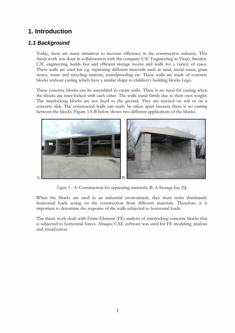
These concrete blocks can be assembled to create walls. There is no need for casting when the blocks are inter-locked with each other. The walls stand firmly due to their own weight. The interlocking blocks are not fixed to the ground. They are stacked on soil or on a concrete slab. The constructed walls can easily be taken apart because there is no casting between the blocks. Figure 1A-B below shows two different applications of the blocks.
A: B:
Figure 1 - A: Construction for separating materials, B: A Storage bay [5].
When the blocks are used in an industrial environment, they must resist dominantly horizontal loads acting on the construction from different materials. Therefore, it is important to determine the response of the walls subjected to horizontal loads.
The thesis work deals with Finite Element (FE) analysis of interlocking concrete blocks that is subjected to horizontal forces. Abaqus/CAE software was used for FE modeling, analysis and visualization.
2
1.2 Purpose & aim
The purpose of this study is to create Finite Element (FE) models that can be used for calculations of the capacity for the interlocking blocks.
1.3 Hypothesis and Limitations
The block in this study has the dimension 1600 x 800 x 800 mm and a weight of 2.4 ton. The interlocking geometry will be limited to C3C Engineering’s design. The concrete quality that is used for the blocks is C20/25.
The FE models will be limited to a maximum height of 2.4 m.
The boundary conditions consist of a pinned connection and springs introduced to the bottom of concrete blocks.
1.4 Literature review
There is no literature dealing with the interlocking concrete blocks even though the building system is common and used in Europe. There are only some web sites from different companies that produce the interlocking concrete blocks.
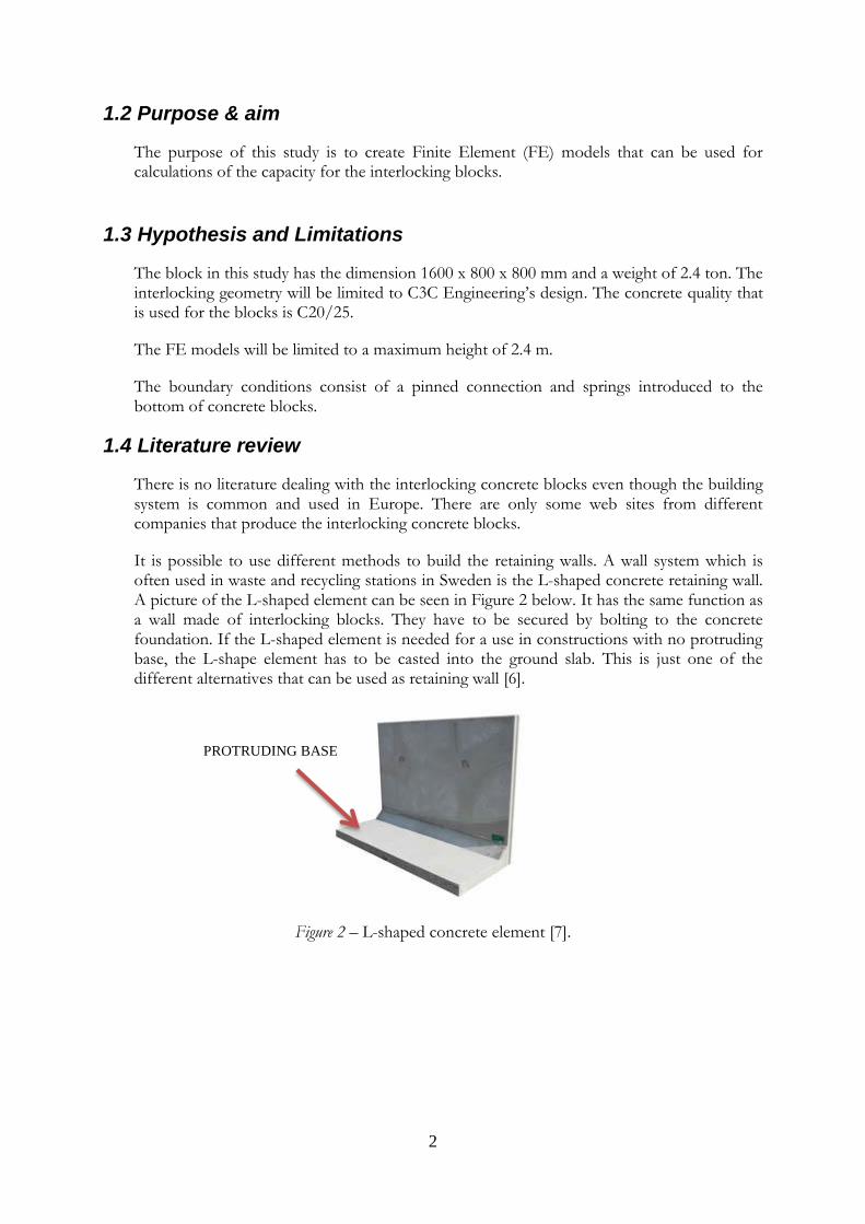
It is possible to use different methods to build the retaining walls. A wall system which is often used in waste and recycling stations in Sweden is the L-shaped concrete retaining wall. A picture of the L-shaped element can be seen in Figure 2 below. It has the same function as a wall made of interlocking blocks. They have to be secured by bolting to the concrete foundation. If the L-shaped element is needed for a use in constructions with no protruding base, the L-shape element has to be casted into the ground slab. This is just one of the different alternatives that can be used as retaining wall [6].
Figure 2 – L-shaped concrete element [7].
PROTRUDING BASE
3
2. Theory
2.1 Concrete
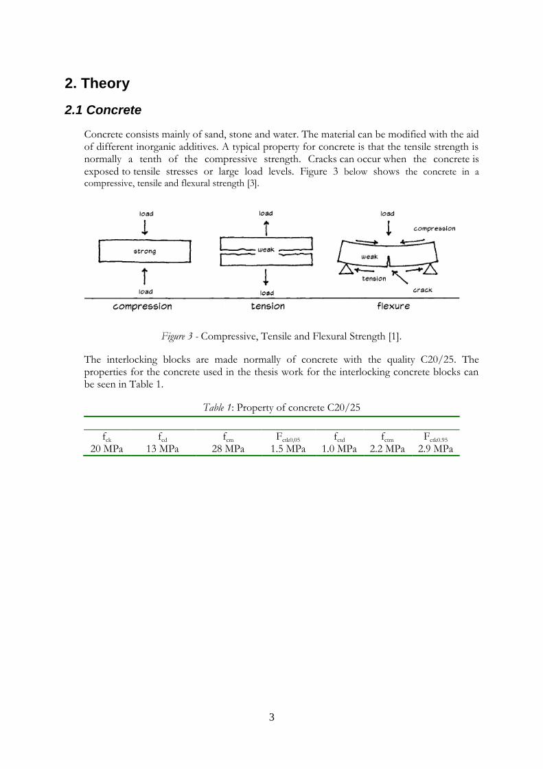
Concrete consists mainly of sand, stone and water. The material can be modified with the aid of different inorganic additives. A typical property for concrete is that the tensile strength is normally a tenth of the compressive strength. Cracks can occur when the concrete is exposed to tensile stresses or large load levels. Figure 3 below shows the concrete in a compressive, tensile and flexural strength [3].
Figure 3 - Compressive, Tensile and Flexural Strength [1].
The interlocking blocks are made normally of concrete with the quality C20/25. The properties for the concrete used in the thesis work for the interlocking concrete blocks can be seen in Table 1.
Table 1: Property of concrete C20/25
fck fcd fcm Fctk0,05 fctd fctm Fctk0.95 20 MPa 13 MPa 28 MPa 1.5 MPa 1.0 MPa 2.2 MPa 2.9 MPa

4
2.2 Interlocking concrete blocks
Interlocking blocks have a lot of use in constructions; for example retaining walls, industrial buildings, erosion control, grain stores, fire-resistant walls and soundproofing.
This type of a building system has a lot of advantages, because it is fast and flexible. It gives a temporary solution that is easily transferable to different places, to remove some parts of it or to expand the constructions. There is no need for a foundation. A stable ground is enough, and this enables fast installation [5].
The block can be made with various knob shapes and sizes for different types of applications.
Dimension and weight of two standard blocks are:
Width: 600 mm Height: 600 mm Length: 1200 mm Weight: 1 ton (not modeled in this thesis)
Width: 800 mm Height: 800 mm Length: 1600 mm Weight: 2.4 ton

5
2.2.1 Knobs on the blocks and the lateral support
The interlocking concrete blocks consist of 8 knobs. These knobs work as an interlocking mechanism in wall constructions. The detailed dimensions of the block and knobs can be seen in Figure 4 below. A picture of how these knobs looks like in reality can be seen in Figure 5-A.
Figure 4 - Block knob dimensions and their displacement.
A lateral support is used to strengthen a wall construction by preventing it against rotation. The wall construction can also be supported by other crossway walls. A picture of a wall support can be seen in Figure 5-B.
A: B:
Figure 5 - A: The knobs of a block, B: A wall with lateral support.

6
2.3 Finite element method in general
The FEM can be used to solve a complicated problem by classical analytical method. It has a numerical approach to the problem by which the general differential equations can be solved in an approximated manner. This is assumed over a certain region that can be one, two or three dimensional. Simplified steps of FEM can be seen in Figure 6 bellow [3].
Figure 6 - Steps in engineering mechanics analysis [4].
The finite element method simplifies the geometry of the model by dividing it into small parts, called finite elements, see Figure 7 below. Every element is represented by an element stiffness matrix. These elements are assembled together into a system of equations that represent the entire model. A more accurate solution can be found if a denser mesh were to be used [4].
Figure 7 - Illustration of modeling steps [4].

7
3. Method
3.1 Hand calculations
Hand calculations have been done to determine which type of failure will occur in a straight wall built by interlocking concrete blocks. Two different failures will be evaluated, 1) the stability against rotation and 2) the shear force failure.
Concrete blocks are dry-stacked on the ground and they resist overturning by their own weight. Two different failure types may occur if a horizontal force is applied to the top block. The first failure type can occur when the top block rotates when enough force is applied, as it can be seen in Figure 8-A below. The second type is shear failure, see Figure 8-B.
A: B:
Figure 8 A: Rotation failure type. B: Shear failure type.
8
3.2 FE model of interlocking concrete block
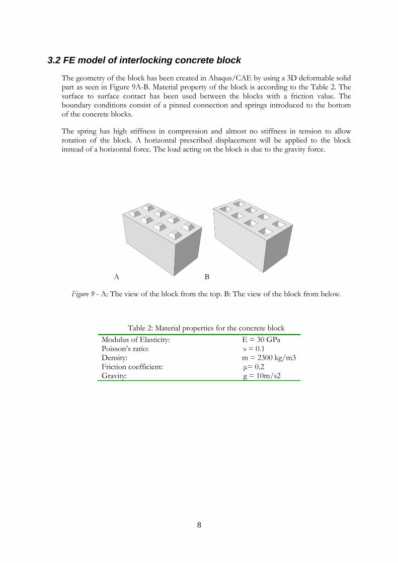
The geometry of the block has been created in Abaqus/CAE by using a 3D deformable solid part as seen in Figure 9A-B. Material property of the block is according to the Table 2. The surface to surface contact has been used between the blocks with a friction value. The boundary conditions consist of a pinned connection and springs introduced to the bottom of the concrete blocks.
The spring has high stiffness in compression and almost no stiffness in tension to allow rotation of the block. A horizontal prescribed displacement will be applied to the block instead of a horizontal force. The load acting on the block is due to the gravity force.
A B
Figure 9 - A: The view of the block from the top. B: The view of the block from below.
Table 2: Material properties for the concrete block
Modulus of Elasticity: E = 30 GPa Poisson’s ratio: ν = 0.1 Density: m = 2300 kg/m3 Friction coefficient: μ= 0.2 Gravity: g = 10m/s2
9
3.2.1 Different FE models
It can be concluded that the rotation failure will occur first according to the results from hand calculations. These results can be seen in chapter 4.1. Hence the thesis will focus only on a rotation failure. Thus different FE model has been created in Abaqus/CAE to simulate the rotation failure.
3.2.1.1 Rotation failure simulation
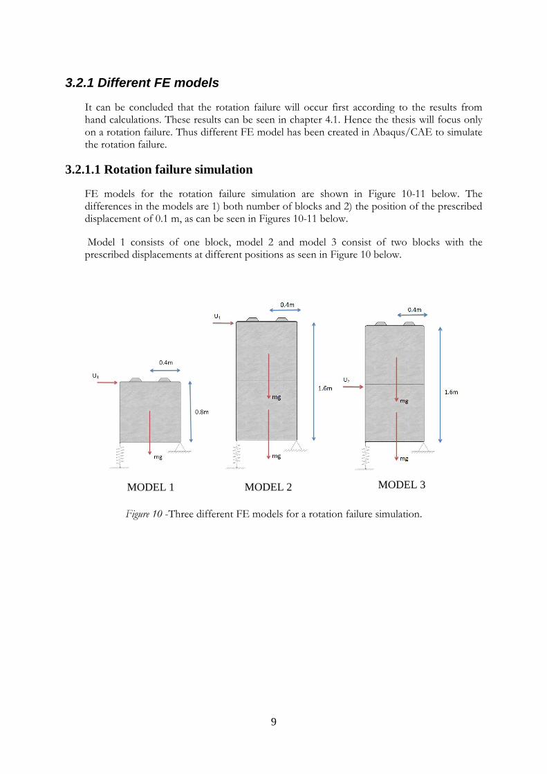
FE models for the rotation failure simulation are shown in Figure 10-11 below. The differences in the models are 1) both number of blocks and 2) the position of the prescribed displacement of 0.1 m, as can be seen in Figures 10-11 below.
Model 1 consists of one block, model 2 and model 3 consist of two blocks with the prescribed displacements at different positions as seen in Figure 10 below.
Figure 10 -Three different FE models for a rotation failure simulation.
MODEL 1 MODEL 2 MODEL 3
10
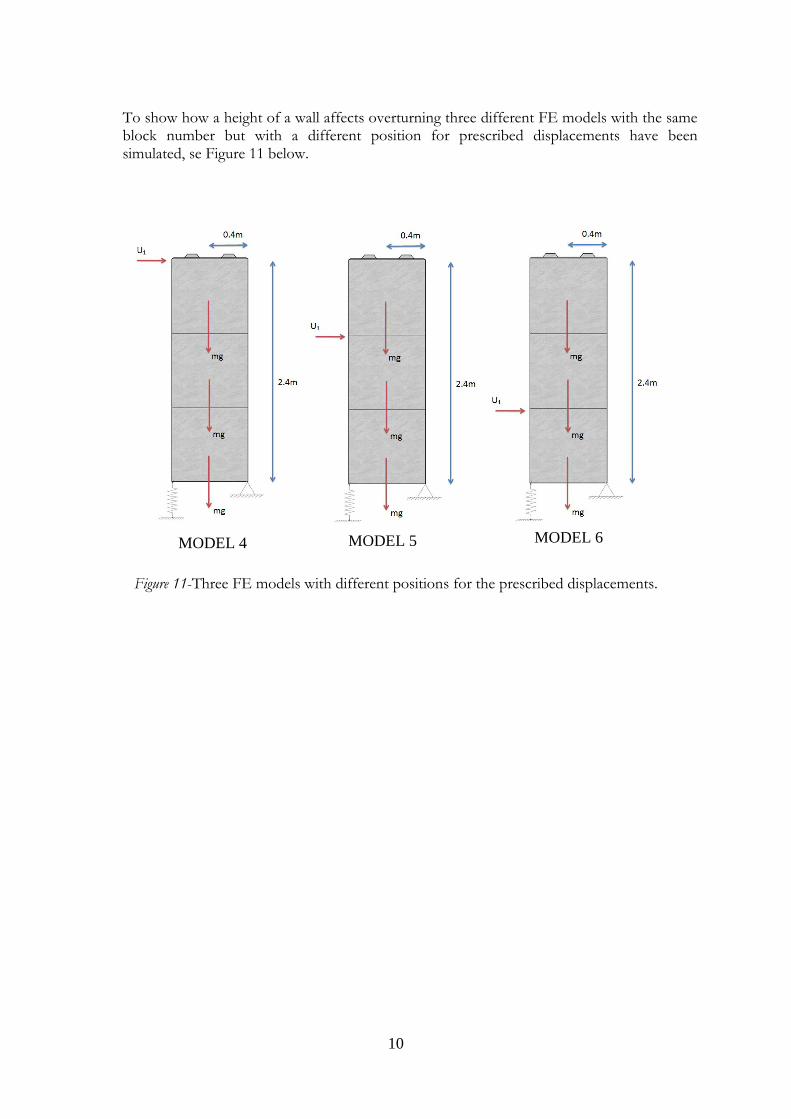
To show how a height of a wall affects overturning three different FE models with the same block number but with a different position for prescribed displacements have been simulated, se Figure 11 below.
Figure 11-Three FE models with different positions for the prescribed displacements.
MODEL 4 MODEL 5 MODEL 6

11
3.2.1.2 FE models of a wall with and without lateral supports
FE model 7 consists of a straight wall without a lateral support. A prescribed displacement has been applied for two positions as can be seen in Figure 12-13 below. The wall dimension is 12 x 2.4 meters.
Figure 12- Side view of the FE model without the lateral supports.
Figure 13 – Top view of the FE model.

12
FE model 8 consists of a wall with lateral supports. The dimension of the wall is 12 x 2.4 m Pinned connections have been applied to model lateral support as seen in Figure 14.
The FE model will be subjected to prescribed displacements as seen in Figure 14-15 below.
Figure 14- Side view of the FE model with lateral supports.
Figure15 - Top view of the FE model with lateral supports.
13
4. Results
4.1 Hand calculations
4.1.1 Rotation
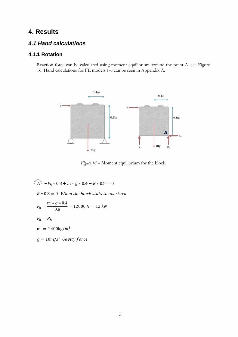
Reaction force can be calculated using moment equilibrium around the point A, see Figure 16. Hand calculations for FE models 1-6 can be seen in Appendix A.
Figure 16 – Moment equilibrium for the block.
A
14
4.1.2 Maximum shear force in the knobs
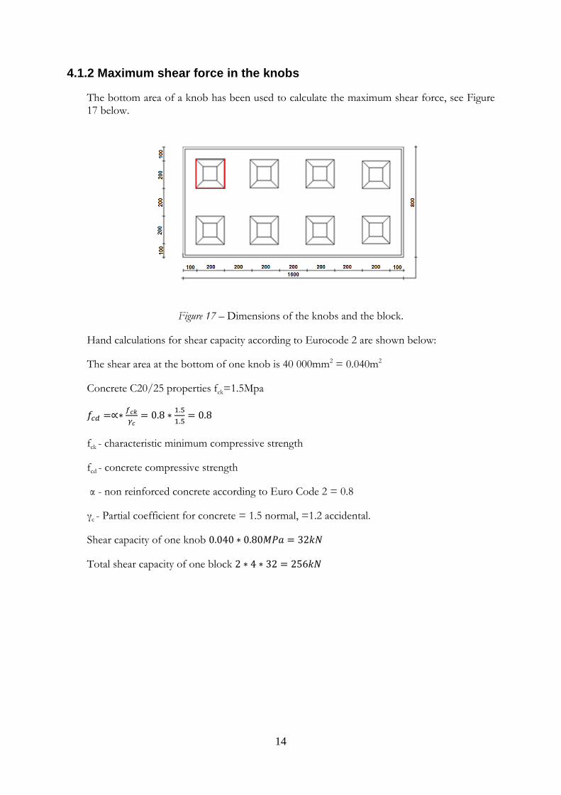
The bottom area of a knob has been used to calculate the maximum shear force, see Figure 17 below.
Figure 17 – Dimensions of the knobs and the block.
Hand calculations for shear capacity according to Eurocode 2 are shown below:
The shear area at the bottom of one knob is 40 000mm2 = 0.040m2
Concrete C20/25 properties fck=1.5Mpa
fck - characteristic minimum compressive strength
fcd - concrete compressive strength
α - non reinforced concrete according to Euro Code 2 = 0.8
γc - Partial coefficient for concrete = 1.5 normal, =1.2 accidental.
Shear capacity of one knob
Total shear capacity of one block
15
4.2 FE results
FE results for eight different models are shown below. The scale factor for contour plots has been chosen to 1. The diagrams consist of two axes. The time axes shows what percentage of the loads is applied in FE analysis. For example when the time is 0.5, 50% of the load has been applied. The values that are used for the diagrams can be seen in Appendix B.
4.2.1 Rotation simulations
4.2.1.1 FE model 1
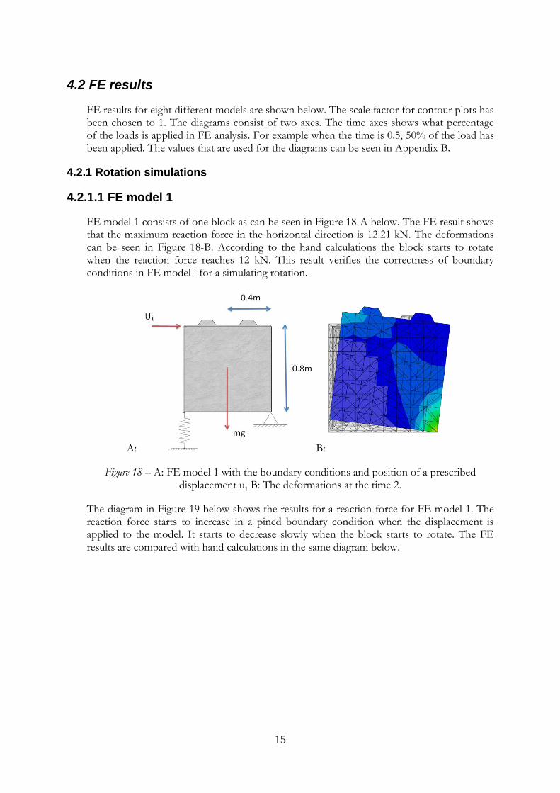
FE model 1 consists of one block as can be seen in Figure 18-A below. The FE result shows that the maximum reaction force in the horizontal direction is 12.21 kN. The deformations can be seen in Figure 18-B. According to the hand calculations the block starts to rotate when the reaction force reaches 12 kN. This result verifies the correctness of boundary conditions in FE model l for a simulating rotation.
A: B:
Figure 18 – A: FE model 1 with the boundary conditions and position of a prescribed displacement u1 B: The deformations at the time 2.
The diagram in Figure 19 below shows the results for a reaction force for FE model 1. The reaction force starts to increase in a pined boundary condition when the displacement is applied to the model. It starts to decrease slowly when the block starts to rotate. The FE results are compared with hand calculations in the same diagram below.

16
Figure 19 –Maximum value of the reaction force for one block. Gravity load is applied during the time interval 0.0-1.0 and a prescribed displacement is applied during the time interval
1.0-2.0.
4.2.1.2 FE models 2 and 3
FE model 2 consists of two blocks stacked on top of each other as can be seen in Figure 20-A. The FE result shows that the maximum horizontal reaction force is 10.64 kN. The deformations can be seen in Figure 21-B. According to the hand calculations the block starts to rotate when the reaction force reaches 12 kN. The reaction forces from the FE analysis are lower compared with the reaction force from the hand calculations. One reason could be that the reaction force is taken in the bottom block. In Abaqus, the top block starts to overturn which affects the results. Overturning of the top block has not been taken in consideration in the hand calculations.
A: B:
Figure 20 – A: FE model 2 with boundary conditions and a prescribed displacement u1. B: The deformations at the time 2 with a scale factor 1.
0
5000
10000
15000
20000
25000
30000
35000
40000
0,0 0,5 1,0 1,5 2,0
Forc
e (
N)
Time
Model 1 horizontal reaction forces
Model 1
Hand calculationsmodel 1

17
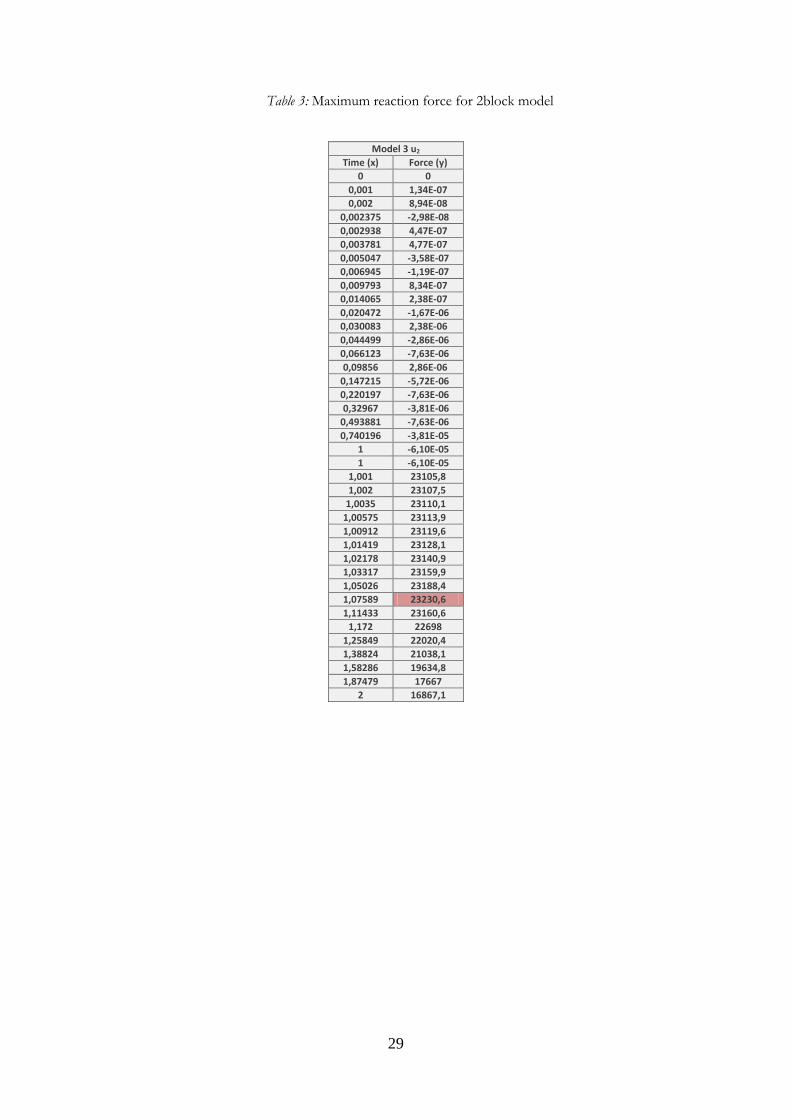
FE model 3 consists of two blocks with the displacement at the bottom block as can be seen in Figure 21-A. The FE result from the model gave a horizontal reaction force of 23.30 kN. The deformations can be seen in Figure 21-B. According to the hand calculations the blocks start to rotate when the reaction force reaches 24 kN. The reason why the reaction forces from the FE analysis are lower compared to the hand calculations may depend on the springs or on the weight from the block above the displacement.
A:
Figure 21 – FE Model 3 with the boundary conditions and the displacement u2. B: The deformations at the time 2 with a scale factor of 1.

18
The reaction forces were collected to the Figure 22 below to compare the models with hand calculations. Abaqus models had slightly minor reaction forces than the hand calculations.
Figure 22- Maximum value of the reaction force for one block. Gravity load is applied during the time interval 0.0-1.0 and a prescribed displacement is applied during the time interval
1.0-2.0
4.2.1.3 FE Models 4, 5 and 6
FE model 4 consists of three blocks with a displacement at the top block as can be seen in Figure 23-A. The FE results from the model shows that the top block turns over at a reaction force of 10.62 kN. The deformations can be seen in Figure 23-B. According to the hand calculations the block starts to rotate when the reaction force reaches 12 kN. The reaction values are the same as for the model 2, therefore the conclusion is the same as for the model 2.
A: B:
Figure 23- A: FE Model 4 with the boundary conditions and the displacement u1. B: The deformations at the time 2 with a scale factor of 1.
0
5000
10000
15000
20000
25000
30000
35000
40000
0 0,5 1 1,5 2
Forc
e (
N)
Time
Model 2 and 3 horizontal reaction forces
Model 2
Model 3
Model 2 handcalculations
Model 3 Handcalculations

19
FE model 5 consists of three blocks with the displacement at the middle block as can be seen in Figure 24-A. The FE results show that the horizontal reaction force is 17.33 kN. The deformations can be seen in Figure 24-B. According to the hand calculations the blocks start to rotate when the reaction force reaches 18 kN. The two top blocks do not start to overturn, as could be assumed because of the previous models. The interlocking works well as the whole construction starts to overturn together.
A: B:
Figure 24 – A: Model 5 with the boundary conditions and the displacement u2. B: The deformations at the time 2 with a scale factor of 1.
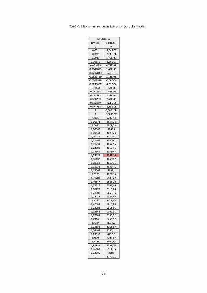
FE model 6 consists of three blocks with the displacement at the bottom block as can be seen in Figure 25-A. The FE result shows that the horizontal reaction force is 34.64 kN. The deformations can be seen in Figure 25-B. According to the hand calculations the block starts to rotate when the reaction force reaches 36 kN. The reaction force seems to differ more from the hand calculations when there are several blocks stacked above the displacement, and as the displacement gets closer to the bottom block. One explanation can be the weight of the blocks from above pushing the construction downwards which in turn affects the reaction forces in the horizontal direction.
A: B:
Figure 25- A: Model 6 with the boundary conditions and the displacement u3. B: The deformations at the time 2 with a scale factor of 1.

20
The diagram in Figure 26 below shows the collected reaction forces compared with the hand
calculations from the different three block models above.
Figure 26 - Maximum value of the reaction force for one block. Gravity load is applied during the time interval 0.0-1.0 and a prescribed displacement is applied during the time interval
1.0-2.0
The summarized results from the hand calculations and the Abaqus model results can be seen in Table 3 below. This shows that the FE models work well as a simulation tool to determine the overturning capacity of the blocks.
Table 3- Summarized results from hand- and Abaqus calculations.
Model type Handcalculations result Abaqus result
Model 1 12 kN 12.21 kN
Model 2
Model 3
Model 4
Model 5
Model 6
12 kN
24 kN
12 kN
18 kN
36 kN
10.64 kN
23.30 kN
10.62 kN
17.33 kN
34.64 kN
0
5000
10000
15000
20000
25000
30000
35000
40000
0,0 0,5 1,0 1,5 2,0
Forc
e (
N)
Time
Model 4,5 and 6 horizontal reaction forces
Model 4
Model 5
Model 6
Model 4 hand calculations
Model 5 hand calculations
Model 6 hand calculations

21
4.2.2 Wall construction results
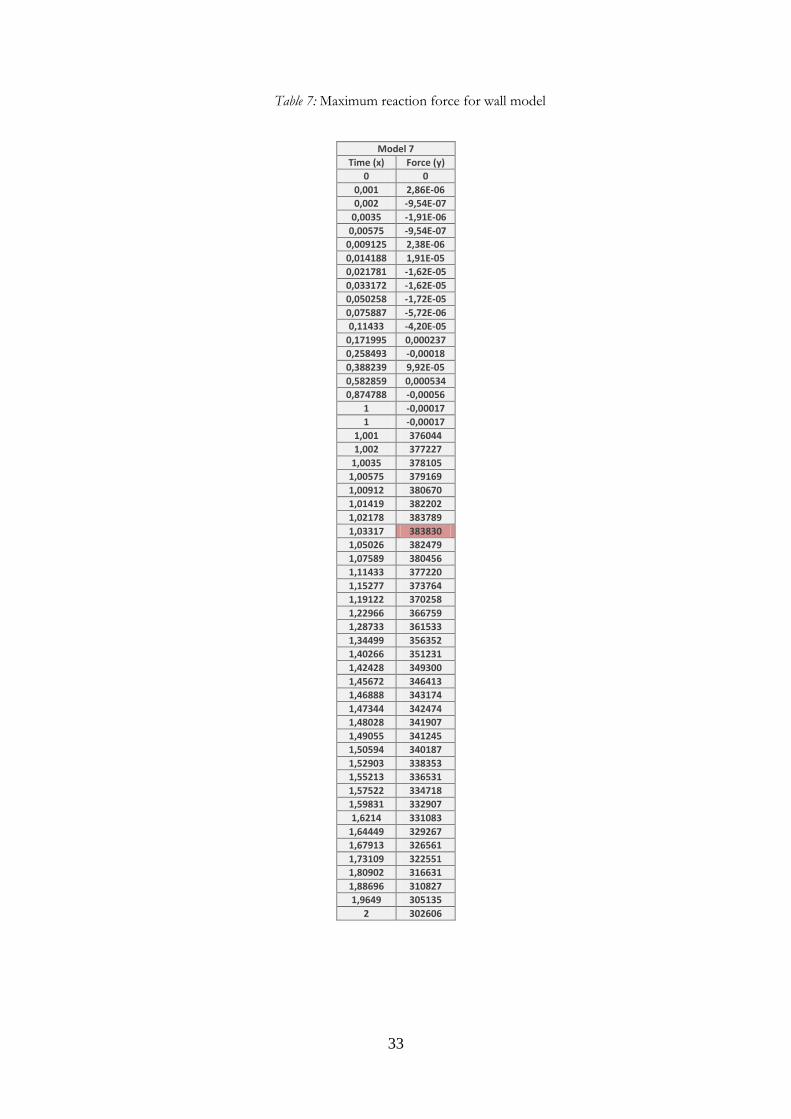
The FE results from model 7 show that the maximum reaction force in the horizontal direction is 383.83 kN, with the displacements u2 and u3 as seen in Figure 27-A. The deformation can be seen in Figure 27-B
Figure 27 – A: Wall model with the boundary conditions and B: The deformations at the time 2 with a scale factor of 1.
The FE results from model 8 show that the maximum reaction force in the horizontal direction is 720kN, with the displacements u2 and u3 as seen in Figure 28-A. The deformations can be seen in Figure 28-B.
A: B:
Figure 28 - Wall model with lateral support and boundary conditions. The deformations at the time 2 with a scale factor of 1.

22
A diagram of the reaction forces in the horizontal direction can be seen in Figure 29. The reaction forces are calculated at the pinned connection when the displacement u2 and u3 are applied.
Figure 29- Maximum value of the reaction force for one block. Gravity load is applied during the time interval 0.0-1.0 and a prescribed displacement is applied during the time
interval 1.0-2.0
If the reaction forces are divided by the length of the wall, a reaction force per meter will be obtained. A wall with dimensions of 12 x 3.2m can withstand the force of 32 kN/m. And a wall with lateral support can withstand a force of 60 kN/m. It is almost twice as much compared with the wall model 7. Adding lateral supports to a construction will in turn increase the horizontal capacity but at the same time increase the risk of shear failure.
0
100000
200000
300000
400000
500000
600000
700000
800000
0,0 0,5 1,0 1,5 2,0
Forc
e (
N)
Time
Model 7 and 8 horizontal reaction forces
Model 7
Model 8
23
5. Discussion & conclusions
By the thesis we have created FE models that can predict rotation failure of the concrete block walls. FE models have been verified through hand calculations. The small differences between the results can be caused by the boundary conditions or the value for the friction coefficient.
Future studies can deal with shear capacity of the walls with supports and corner constructions. Because friction has an influence on the results, future studies can deal with finding the correct value by another experiment.
A second alternative is to make explicit models where it is possible to follow the rotation of the blocks until they fall of, and get a more real behavior on how the blocks overturn in reality.
The FE models that we have created can be used for the design of interlocking concrete block walls.

24
6. References
Literature:
[1] Beall Christine, Rochelle Jaffe, Concrete and Masonry Databook, ISBN: 0071361545
[2] Engström, B. Beräkning av betongkonstruktioner, rapport 2007:13, rev. 2008, Chalmers
tekniska högskola. [3] Lawrence Taylor Richard , Leroy Taylor Robert , O. C. Zienkiewicz, , The finite element
method for solid and structural mechanics, 2005, ISBN-13: 9780750663229
[4] Ottosen N.S., H. Petersson; Introduction to the Finite Element, Prentice Hall, 1992. 410pages, ISBN 0-13-473877-2
Word Wide Web:
[5] Interlocking concrete blocks, 2011-02-20, 10:42 http://www.c3c.se/pdf/c3c_folder.pdf
[6] Retaining wall systems 2010-05-12, 15:12 http://www.jpconcrete.co.uk/heavy-duty-retaining-wall.htm
[7] Retaining wall element L-shape 2010-05-12, 16:02 http://www.starka.se/index_grupper.asp?grpid=4&menu=on

25
7. Appendix
Appendix A- Hand calculations Appendix B- Maximum reaction forces

26
Appendix A
In the hand calculations the displacement value u has been changed to force Fh.
Model 1
Model 2
Model 3
Model 4
Model 5
Model 6

27
Appendix B
Diagram input:
Table 1: Maximum reaction force for 1block Model 1 u1
Time (x) Force (y)
0 0
0,001 1,04E-07
0,002 5,96E-08
0,0035 -5,96E-08
0,00575 0
0,009125 1,79E-07
0,0141875 -3,58E-07
0,0217813 -2,38E-07
0,0331719 -2,38E-07
0,0502578 -9,54E-07
0,0758867 9,54E-07
0,11433 9,54E-07
0,171995 9,54E-07
0,258493 0
0,388239 -9,54E-06
0,582859 2,29E-05
0,874788 -2,29E-05
1 2,29E-05
1 2,29E-05
1,001 11559,2
1,002 11566,5
1,0035 11577,5
1,00575 11593,8
1,00912 11618,4
1,01419 11655,1
1,02178 11710,1
1,03317 11792,3
1,05026 11914,9
1,07589 12097,4
1,11433 12235,1
1,172 12079,9
1,25849 11852,7
1,38824 11523,7
1,58286 11054,5
1,87479 10397,6
2 10131,3

28
Table 2: Maximum reaction force for 2block model
Model 2 u 1
Time (x) Force (y)
0 0
0,001 1,34E-07
0,002 8,94E-08
0,002375 -2,98E-08
0,0029375 4,47E-07
0,00378125 4,77E-07
0,00504688 -3,58E-07
0,00694531 -1,19E-07
0,00979297 8,34E-07
0,0140645 2,38E-07
0,0204717 -1,67E-06
0,0300825 2,38E-06
0,0444988 -2,86E-06
0,0661232 -7,63E-06
0,0985598 2,86E-06
0,147215 -5,72E-06
0,220197 -7,63E-06
0,32967 -3,81E-06
0,493881 -7,63E-06
0,740196 -3,81E-05
1 -6,10E-05
1 -6,10E-05
1,001 9863,91
1,00175 9956,71
1,0025 10041,5
1,00363 10134,6
1,00531 10257,8
1,00784 10432,5
1,01164 10607,3
1,01734 10620,7
1,02588 10641,6
1,03869 10647,7
1,05151 10617,6
1,06432 10587,3
1,07714 10556,9
1,09636 10511,1
1,12519 10442,5
1,16844 10339,3
1,23331 10183,6
1,33062 9954,91
1,42793 9730,11
1,52524 9499,46
1,62255 9262,03
1,71986 9027,8
1,72594 9014,45
1,72746 9011,14
1,72898 8406,05
1,7305 8466,94
1,73203 8526,48
1,73431 8612,93
1,73773 8736,99
1,74286 8753,41
1,74799 8742,63
1,75312 8731,87
1,76082 8715,88
1,77237 8692,29
1,78968 8657,79
1,81566 8606,86
1,85463 8532,84
1,91308 8426,6
2 8269,82
29
Table 3: Maximum reaction force for 2block model
Model 3 u2
Time (x) Force (y)
0 0
0,001 1,34E-07
0,002 8,94E-08
0,002375 -2,98E-08
0,002938 4,47E-07
0,003781 4,77E-07
0,005047 -3,58E-07
0,006945 -1,19E-07
0,009793 8,34E-07
0,014065 2,38E-07
0,020472 -1,67E-06
0,030083 2,38E-06
0,044499 -2,86E-06
0,066123 -7,63E-06
0,09856 2,86E-06
0,147215 -5,72E-06
0,220197 -7,63E-06
0,32967 -3,81E-06
0,493881 -7,63E-06
0,740196 -3,81E-05
1 -6,10E-05
1 -6,10E-05
1,001 23105,8
1,002 23107,5
1,0035 23110,1
1,00575 23113,9
1,00912 23119,6
1,01419 23128,1
1,02178 23140,9
1,03317 23159,9
1,05026 23188,4
1,07589 23230,6
1,11433 23160,6
1,172 22698
1,25849 22020,4
1,38824 21038,1
1,58286 19634,8
1,87479 17667
2 16867,1

30
Table 4: Maximum reaction force for 3blocks model
Model 4 u3
Time (x) Force (y)
0 0
0,001 -1,04E-07
0,002 -2,98E-08
0,0035 1,79E-07
0,00575 -3,58E-07
0,009125 4,77E-07
0,0141875 1,43E-06
0,0217813 -9,54E-07
0,0331719 2,86E-06
0,0502578 -6,68E-06
0,0758867 -7,63E-06
0,11433 1,53E-05
0,171995 1,53E-05
0,258493 3,81E-05
0,388239 7,63E-05
0,582859 -4,58E-05
0,874788 -6,10E-05
1 -0,00012207
1 -0,00012207
1,001 34642,7
1,002 34626,9
1,0035 34603,2
1,00575 34567,8
1,00912 34514,6
1,01419 34435
1,02178 34315,9
1,03317 34137,8
1,05026 33871,9
1,07589 33475,4
1,11433 32888,4
1,172 32021
1,25849 30749,7
1,38824 28905,5
1,58286 26267,4
1,87479 22560,7
2 21051,2

31
Table 5: Maximum reaction force for 3blocks model
Model 5 u2
Time (x) Force (y)
0 0
0,001 -1,04E-07
0,002 -2,98E-08
0,0035 1,79E-07
0,00575 -3,58E-07
0,009125 4,77E-07
0,0141875 1,43E-06
0,0217813 -9,54E-07
0,0331719 2,86E-06
0,0502578 -6,68E-06
0,0758867 -7,63E-06
0,11433 1,53E-05
0,171995 1,53E-05
0,258493 3,81E-05
0,388239 7,63E-05
0,582859 -4,58E-05
0,874788 -6,10E-05
1 -0,00012207
1 -0,00012207
1,001 17325,3
1,002 17321,7
1,0035 17316,4
1,00575 17308,3
1,00912 17296,3
1,01419 17278,2
1,02178 17251,1
1,03317 17210,5
1,05026 17149,7
1,07589 17058,6
1,11433 16922,4
1,172 16719,2
1,25849 16416,2
1,38824 15966,1
1,58286 15300,3
1,87479 14321,3
2 13908,5
32
Table 6: Maximum reaction force for 3blocks model
Model 6 u1
Time (x) Force (y)
0 0
0,001 -1,04E-07
0,002 -2,98E-08
0,0035 1,79E-07
0,00575 -3,58E-07
0,009125 4,77E-07
0,0141875 1,43E-06
0,0217813 -9,54E-07
0,0331719 2,86E-06
0,0502578 -6,68E-06
0,0758867 -7,63E-06
0,11433 1,53E-05
0,171995 1,53E-05
0,258493 3,81E-05
0,388239 7,63E-05
0,582859 -4,58E-05
0,874788 -6,10E-05
1 -0,0001221
1 -0,0001221
1,001 9785,44
1,00175 9884,78
1,0025 9972,78
1,00363 10085
1,00531 10206,3
1,00784 10304,1
1,01164 10400,1
1,01734 10527,6
1,02588 10604,1
1,03869 10630,3
1,05151 10633,6
1,06432 10602,7
1,08354 10556,1
1,11238 10486,1
1,15563 10381
1,2205 10222,6
1,31781 9988,22
1,46377 9646,76
1,57325 9384,45
1,68272 9115,26
1,71009 9050,36
1,72035 9027,46
1,7242 9018,88
1,72564 9015,84
1,72781 9011,06
1,72862 9009,31
1,72984 8396,52
1,73166 8469,12
1,7344 8574,3
1,73851 8723,59
1,74468 8750,12
1,75393 8730,8
1,7678 8702,07
1,7886 8660,38
1,81981 8599,24
1,86663 8511,35
1,93685 8384
2 8270,21
33
Table 7: Maximum reaction force for wall model
Model 7
Time (x) Force (y)
0 0
0,001 2,86E-06
0,002 -9,54E-07
0,0035 -1,91E-06
0,00575 -9,54E-07
0,009125 2,38E-06
0,014188 1,91E-05
0,021781 -1,62E-05
0,033172 -1,62E-05
0,050258 -1,72E-05
0,075887 -5,72E-06
0,11433 -4,20E-05
0,171995 0,000237
0,258493 -0,00018
0,388239 9,92E-05
0,582859 0,000534
0,874788 -0,00056
1 -0,00017
1 -0,00017
1,001 376044
1,002 377227
1,0035 378105
1,00575 379169
1,00912 380670
1,01419 382202
1,02178 383789
1,03317 383830
1,05026 382479
1,07589 380456
1,11433 377220
1,15277 373764
1,19122 370258
1,22966 366759
1,28733 361533
1,34499 356352
1,40266 351231
1,42428 349300
1,45672 346413
1,46888 343174
1,47344 342474
1,48028 341907
1,49055 341245
1,50594 340187
1,52903 338353
1,55213 336531
1,57522 334718
1,59831 332907
1,6214 331083
1,64449 329267
1,67913 326561
1,73109 322551
1,80902 316631
1,88696 310827
1,9649 305135
2 302606

34
Table 8: Maximum reaction force for wall with support model
Model 8
Time (x) Force (y)
0 0
0,001 22,7897
0,00125 22,1886
0,001344 22,3385
0,001484 23,0624
0,001695 24,4528
0,002012 26,527
0,002486 29,3911
0,003198 33,0894
0,004266 38,0166
0,005868 44,8686
0,008271 55,2817
0,011875 71,1873
0,017281 95,8587
0,02539 132,47
0,037554 185,366
0,055799 264,345
0,083168 382,806
0,12422 561,343
0,185799 830,607
0,278167 1235,74
0,41672 1845,13
0,624548 2760,65
0,936291 4135,1
1 4416,08
1 4416,08
1,001 73552,1
1,002 154362
1,0035 278350
1,00575 442481
1,00912 519701
1,01419 575526
1,02178 624206
1,03317 660566
1,03744 669991
1,04385 682002
1,05346 691679
1,06788 701937
1,0895 713643
1,09761 714656
1,10977 715874
1,12802 716852
1,15539 717762
1,19644 718664
1,25802 719715
1,35039 720331
1,48894 719089
1,69677 716210
1,77258 715085
1,88629 712948
1,91472 712400
1,95736 711564
2 710730

35
School of Technology and Design
SE- 351 95 Växjö Sweden
Tel: +46 470-70 80 00, Fax +46 470-76 85 40 www.lnu.se