fulltext01_2
TRANSCRIPT

June 2009Robert Nilssen, ELKRAFT
Master of Science in Energy and EnvironmentSubmission date:Supervisor:
Norwegian University of Science and TechnologyDepartment of Electrical Power Engineering
Design and testing of Flux SwitchedPermanent Magnet (FSPM) Machines
Njål Rotevatn


Problem DescriptionThe novel Flux Switching concepts for Permanent Magnet machines are to be investigated interms of a theoretical survey of relevant literature and by building a prototype for practicalevaluation of the concepts. The main academic focus of the work is the planning of the machineand laboratory instrumentation setup and the testing/evaluation of relevant parameters. Themachine is to be tested as a generator with a passive load.
The student must choose a prototype design and order parts such as magnets and lamination incooperation with the Workshop at NTNU. Planning of the assembly and the building of a labtesting jig is also a part of this work.
In order to give a good validation of the machine, the student must present analysis resultsfocusing on flux densities and flux switching sequences. These theoretical results are expected tobe the basis for laboratory oriented experiments with resistive and capacitive loading of themachine, where machine parameters such as induced voltage, inductances, losses and efficiencyare determined.
Assignment given: 02. February 2009Supervisor: Robert Nilssen, ELKRAFT


1
Design and testing of Flux Switched PermanentMagnet (FSPM) Machines
Njål Rotevatn
Abstract—This thesis offers a short overview of the mostimportant stator mounted permanent magnet machines, with acloser look on the FSPM design. A FSPM machine have beenbuilt and tested as a generator, to get a better understanding ofthe machine concept.
The focus of the work have been on the well documented12/10 (Stator teeth/ Rotor teeth) design while the novel 12/14pole design have also been tested, as a rotor change is the onlydifference between the two designs.
The machine have been simulated in COMSOL, where induc-tances, back emf and cogging have been found and comparedwith the measured results.
Index Terms—FSPM, Electrical machine, PM.
I. INTRODUCTION
BRUSHLESS permanent magnet machines are usuallydesigned with magnets in the rotor, rotor-PM machines.
In recent years there have however been much research onmachines with the magnets mounted in the stator, stator-PMmachines.
Stator mounting of the PMs mainly give two advantages:The heat sensitive magnets can more easily be cooled, andthe magnets will not be subjected to the centrifugal forces of aspinning rotor. Several designs exists for stator-PM machines,where the DSPM (Doubly salient permanent magnet) and theFRM (Flux reversal machine) are the most noteworthy togetherwith the FSPM. They are all doubly salient machines wherethe rotor position determines the path of the stator magnetflux, and hence the stator coil flux coupling.
DSPM: The DSPM machine, Figure (2) have magnetsmounted tangentially in the stator, with a phase numberdependent set of stator teeth between them. This configurationgive a trapezoidal back emf and have unipolar flux couplingin the stator coils. A comparison between FSPM and DSPMmachines done in [1], concludes that the DSPM is inferior tothe FSPM in terms of torque density, but have better coggingperformance and higher torque per magnet volume.
FRM: The three phase FRM machine, Figure (3), was intro-duced in [2]. It has two surface mounted magnets at each statortooth, a configuration that give a bipolar flux coupling, and atrapezoidal or sinusoidal back emf depending on the machinedesign. The FRM have magnets in the air gap, magneticallyin series with the coils. This design give problems related tothe fastening of the magnets as well as magnet eddy currentlosses. The series placement of the magnets will additionallycontribute to higher air gap reluctance, and hence lower themachine inductances.
Figure 1. The 12/10 FSPM machine built for the thesis
Figure 2. A 12/8 DSPM machine
FSPM: The FSPM principle was first proposed as a singlephase machine [3], Figure (4), and have recently gained muchinterest with the polyphase designs introduced in [4], similarto the. The winding configuration of the 3-phase machines,Figure (1), is seen to have changed from that of the 1955proposal, but the flux switching principle remains the same.
The FSPM machine is very similar to the DSPM machinein that it has tangentially placed magnets in the stator. Theunique feature of the FSPM is that each winding is placedaround a set of two stator teeth, with one tangentially placedmagnet between them, this give bipolar flux linkage in thecoils, similar to the FRM machine, but without the drawback

2
Figure 3. A 8/12 FRM machine
Figure 4. The first FSPM machine as introduced in 4
of surface mounted magnets. The back-emf of the three phasemachines to be examined in this thesis is naturally sinusoidal,making them suitable for brushless AC.
A wide variety of alternative flux switching designs arepresented in literature, they can not all be thoroughly presentedin this paper, but a few examples are still presented, to showsome of the possibilities of flux switching machines:
-Multi tooth FSPM machines, as they are presented in [5],[6], claims to both give higher torque and lower magnet thanthe conventional FSPM machine, at least at low current levels.
-Parallel Path Magnetic Technology (PPMT). [7] presentswhat appears to be FSPM machines with a winding layoutsimilar to that of [3] under the name PPMT. These machines
claim to be superior to most other machines, but the amountof advertisement in these claims are uncertain
-The FSPM design is proposed as an linear actuator in [8],an interesting design where the advantages of convectionallinear tubular machines are combined with that of the FSPMdesign; No end windings and no magnets on the moving part,this facilitates easier magnet cooling and decouples the magnetvolume from stroke length of the machine.
-Current exited flux switching machines for use in powertools are presented in [9]. The design removes the needfor brushes used in the common universal machines, and isclaimed to be very cost effective. Black and Decker haveaccording to the paper actually launched a flux switching basedtabled saw on the design.
II. FSPM OPERATING PRINCIPLES AND IMPORTANTPARAMETERS
A. The flux switching sequence
Figure 5. The flux switching principle
The flux switching sequence of a FSPM machine can beseen in Figure (5). It is seen how the flux in each statortooth is unipolar, while the combination of two stator teethin each stator pole give a bipolar coil flux coupling, switchingdirection with rotor position. The figure explains the principlebehind flux switching well, but in practice with the number ofstator poles 6= the number of rotor poles it is fairly complicatedto determine the exact flux switching sequence, as it is aninterplay between all the stator rotor air gaps. It should alsobe observed that there will be some leakage flux betweenthe stator teeth inside each pole, this will obviously be moresignificant if the rotor poles are wide, and if the number ofrotor poles> the number of stator poles.
B. Number of stator polesA simple but important factor of rotating FSPM machines
are that the number of stator teeth must always be an evennumber, as stator magnets must alternate in magnetizationdirection. In a circular setup in a rotating machine this requiresan even number of poles.
C. Fundamental frequencyOne electrical period of an FSPM machine is equal to the
time it takes for the position of a rotor tooth at the startof a period to be filled by the next tooth, thus putting themachine into the same magnetic state as it was at the beginningof the period, similar to a rotor-PM machine, but withoutpole polarity. The number of electrical periods per mechanicalrevolution of the machine is therefore equal to the number ofrotor teeth, giving the electrical frequency fe = Nr×rpm
60 .

3
D. Radial forces
The magnetically forces in a FSPM machine will alwayspull radially on the rotor teeth. The sum of these forces aredesired to be as low as possible, and at particularly to notoscillate in direction or strength, as this will induce vibrationswith negative effects on machine durability, in particularlybearing life. A simple way of removing the radial forces ischoose a machine where Nr (number of rotor teeth) and Ns(number of stator teeth) have a common factor larger than one.Such machines will have comparatively higher fundamentalfrequencies, making them less suited for high speed operation,as the fundamental frequency is an important part of the lossesin an electrical machine, [10] examines a 5/6 FSPM machinewith particular focus on radial forces.
E. Cogging torque and skewing
The cogging torque in a rotating electrical machine can beexpressed as T (θ) = dW (θ)
dφ(θ) where W is the magnetic energyin the machine, and φ is the angular position of the rotor. Thecalculation of these forces requires detailed modeling of themachine. The number of cogging periods per electrical periodis however easy to find and is equal Ns/HCF (Ns &Nr)where HCF is the highest common factor. This give a cog-ging frequency fc = Nr×Ns
HCF (Ns &Nr)rpm60 . These relations are
easily verified by observing how each electrical period of themachine give the specified number of equal magnetic energystates.
The rotor of an FSPM machine are usually made of steellaminations, this means that it can easily be skewed by angu-lary displacing the lamination sheets. The effect of skewingis that of an moving average filter, and can generally beexpressed as g(x) = 1
Y
∫ Y0f(x + y)dy, where f(x) is the
function of the variable is question before skewing, x is theposition, Y is the skewing and g(x) is the resulting functionafter skewing. For f(x) = sin(x), such as the fundamentalcomponent of the back emf, this can be shown to becomeg(x)= cos(x+0)−cos(x+Y )
Y . From this it can be seen that skewingequal to the length of one cogging period will completely re-move cogging, while the effect on the fundamental componentof the back emf will be small if fc sufficiently much largerthan fe. [11] Examines the effect of skewing for a 6/5 and6/4 FSPM, skewing apparently shows favorable results for theharmonics content of the back emf as well as for the cogging.
F. Torque equations
The torque equations of 3-phase synchronous machines arebest described by examining the machine in a dq referenceframe. Phase values are transformed to dq values by Equations(1-3).
W =23
1/√
3 1/√
3 1/√
3cos(φ) cos(φ− 2π
3 ) cos(φ− 4π3 )
sin(φ) sin(φ− 2π3 ) sin(φ− 4π
3 )
(1)
i0idiq
= W ×
iaibic
(2)
v0vdvq
= W ×
vavbvc
(3)
Machine torque can than be found by Equation (4), where
T =32Nr(λpmiq + (Ld − Lq)idiq) (4)
Where λpm is the PM flux linkage. Reluctance torquein FSPM machines are negligible, and the equation can bereduced to:
T = kT iq (5)
where kT is the torque constant kT = 32Nrλpm, alternatively
kT = 3vq
2ωm, at an unloaded machine, where vq equals the peak
value of the per phase back emf Ef , easily measured at theterminals of an unloaded machine.
III. CHOICE OF FSPM GEOMETRY
Several geometries where examined such as 5/6, 11/12and 13/12 layout. The 11/12 and 13/12 layout was found topromising for a setup with only every other stator pole woundas covered in [12], [13]. The 5/6 machine would be fairlysimple to make with only 6 stator teeth, and would be suitedfor high speed, as it have a low fundamental frequency. All thethese designs are however magnetically unbalanced, an extrafactor that would have had to be considered if one of thesemachines where built.
The geometry finally chosen for the prototype machine is a12 pole stator with a changeable rotor of 10 or 14 poles.
The 12/10 configuration is well covered in literature suchas [14], [15], [10], [1], [16], [4] and more. It has balancedradial magnet forces from symmetry, thus making it a suitableintroduction to FSPM machine design.
The 12/14 was chosen in order run an initial test on thispromising geometry. The idea is that the relatively higherfundamental frequency of a 14 pole rotor will give 40% highertorque than a 10 pole rotor at the same λpm (Equation (4)).
The 12/10 and 12/14 machines have similar stator layoutwith the only difference being that the 14 pole machine havenegative phase sequence when compared with the 10 polemachine. The only major operation in changing from the 12/10to the 12/14 layout is therefore the rotor change.
A. Machine optimization theory
The main focus of the thesis was to build and test a FSPMmachine prototype, the time spent optimizing the design wouldtherefore have to be limited. The principles of [15], [14], aswell as some qualitative results from the lumped parametermodel developed was used to decide the layout of the machine.With fem analysis used mainly to confirm that the chosendesign was reasonable with respect to cogging torque andvoltage waveforms. Only the 12/10 machine was consideredin the optimization, as time was limited.
FSPM optimization as covered in literature, and used in thisthesis, is based on what might be called the reference design

4
where magnets, stator teeth, winding slots as well as rotorteeth and back iron that are all of the same width1.
The relationship between these variables as well as theair gap length and inner-/outer stator diameter fully definesthe machine 2D layout (as long as alternative magnet androtor-/stator teeth shapes are disregarded). The main geometricrelations important for FSPM machine performance are:
-Magnet-/Slot width vs stator tooth width. The magnets,winding slots and stator teeth in an FSPM machine are evenlyspaced to achieve symmetry, this means that a increase instator tooth width, means an equal decrease in magnet- andwinding slot width. Changes in this variable is a trade offbetween flux path reluctance and magnet-/copper volume. [15]say that the stator teeth should be equal to that of the magnetwidth, while [14] concludes that the stator teeth should bewidened approximately 10% when the rotor tooth with areexamined together with the rotor tooth width.
-Back iron width. Leakage flux as well as the fact that theflux in the stator teeth have two back iron paths, one formeach neighboring pole, to divide into. Back iron flux densityis therefore lower that that in the stator teeth, a decrease inback iron width, bringing the back iron closer to saturation willallow for more copper at the same outer diameter. A reductionto 70% of the original value is prescribed in [15]
-Magnet back iron bridge. It is possible to have a smallbridge between the stator segments, allowing the stator to beproduced in one piece easing the production of the machine.This will have a negative effect on machine performance, thisis covered in [15].
-Split ratio, outer/inner stator diameter. As with all machinesthere is a balancing between inner stator diameter, as thesedecide the torque arm and the torque producing area of amachine, as well as the copper volume, and in FSPM machinesalso the magnet area.
-Rotor teeth width. The rotor tooth width is important inthe determination of the machine back emf, as it influencesthe flux switching timing and the reluctance of the flux path.1.46 times the base value is prescribed in [15].
1) Final 12/10 Design: The final design specifications islisted in Table (I). The chosen machine design have rotor-/stator diameters of a little more than twice that of themachines in [15], [14], but the air gap in the chosen machinedesign is doubled as well, meaning that flux density and theshape of the back emf should be similar to that of the men-tioned papers. The split have also been chosen to be similarto the smaller machines, this choice is however somewhatquestionable. A machine whose diameter is doubled, with allother parameters kept the same, as is approximately the casewith the machine in question, will need double the numberof ampere turns to keep the flux density contribution fromthe windings at the same level. The copper area in the samemachine will however grow with the square of the diameter,giving ~twice the flux contribution from the windings perAmpere than that of the smaller machine.
1This is a small lie since the stator teeth are not pointing directly towardsthe center of the machine, they are instead in parallel with the magnets. Thestator teeth are hence cut at an angle in the air gap, giving a stator tooth airgap width that is different (1% in 12 poled stator) from the stator tooth width.
Table IMACHINE SPECIFICATIONS
Number of phases 3Number of stator teeth 12Number of rotor poles 10/14Outer diameter of stator 210mmInner diameter of stator 129.87mmAir gap length 1mmActive axial length 50mmNumber of turns per pole 174Magnet remanence 1.16TMagnet relative permeability 1.05Copper fill factor 0.5Rated Torque 28Rated speed 400rpmRotor tooth width top/bottom 13/18mmStator back iron width 6.3mmStator tooth width 8.91mmMagnet width 8mmRotor tooth height 18.3mmStator support bridge 1.5mm
Machine volume and mass are listed in Table (II). Themachine volume is somewhat difficult to determine becauseof the end windings, and have been calculated as 1.2πR2
sLa,where Rs is outer stator diameter, La is the active length ofthe machine, giving the active volume of the machine plus20% for end windings.
Table IIMASS AND VOLUME OF THE MACHINE
Volume MassSheet steel 10 pole 0.94dm3 7.2kgSheet steel 14 pole 1.00dm3 7.7kg
Magnets 0.175dm3 1.3kgCopper 0.33dm3 2.9kg
Total 10 pole 2.1dm3 11.9kgTotal 14 pole 2.1dm3 11.5kg
2) Final 12/14 Design: The 14 tooth rotor was made withthe same dimensions as the 10 tooth rotor, as no optimizationcalculations had been performed on the 14 pole rotor. Thisdesign is however unlikely to be the best for the 14 pole rotor.One factor in particular is the leakage flux depicted in the lastpart, Figure (5), as this will lead to increased iron losses andprobably lower back emf than the optimum rotor pole width.
IV. CONSTRUCTION
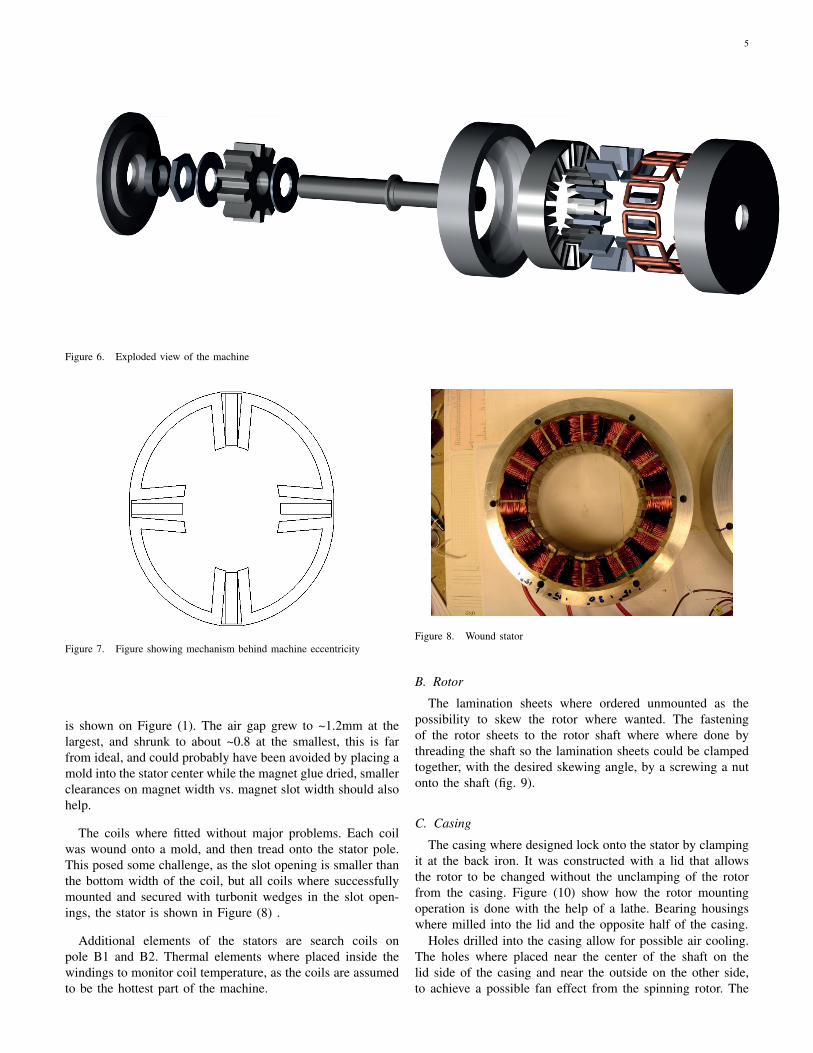
All parts where drawn in Solid Works, to get drawings forproduction purposes as well as visualization of the machine.Solid Works drawings are seen in Figure (6) and on the frontpage.
A. Stator
The stator stack where ordered fully assembled, leaving onlythe mounting of winding and magnets. The magnets whereeasily glued into their slots, but the stator became eccentricbecause the magnetic forces caused stator to shift so that allthe clearance between magnets and the magnet slots ended upin two opposite stator slots. The general principle behind thisis shown in Figure (7), while the orientation of this eccentricity
5
Figure 6. Exploded view of the machine
Figure 7. Figure showing mechanism behind machine eccentricity
is shown on Figure (1). The air gap grew to ~1.2mm at thelargest, and shrunk to about ~0.8 at the smallest, this is farfrom ideal, and could probably have been avoided by placing amold into the stator center while the magnet glue dried, smallerclearances on magnet width vs. magnet slot width should alsohelp.
The coils where fitted without major problems. Each coilwas wound onto a mold, and then tread onto the stator pole.This posed some challenge, as the slot opening is smaller thanthe bottom width of the coil, but all coils where successfullymounted and secured with turbonit wedges in the slot open-ings, the stator is shown in Figure (8) .
Additional elements of the stators are search coils onpole B1 and B2. Thermal elements where placed inside thewindings to monitor coil temperature, as the coils are assumedto be the hottest part of the machine.
Figure 8. Wound stator
B. Rotor
The lamination sheets where ordered unmounted as thepossibility to skew the rotor where wanted. The fasteningof the rotor sheets to the rotor shaft where where done bythreading the shaft so the lamination sheets could be clampedtogether, with the desired skewing angle, by a screwing a nutonto the shaft (fig. 9).
C. Casing
The casing where designed lock onto the stator by clampingit at the back iron. It was constructed with a lid that allowsthe rotor to be changed without the unclamping of the rotorfrom the casing. Figure (10) show how the rotor mountingoperation is done with the help of a lathe. Bearing housingswhere milled into the lid and the opposite half of the casing.
Holes drilled into the casing allow for possible air cooling.The holes where placed near the center of the shaft on thelid side of the casing and near the outside on the other side,to achieve a possible fan effect from the spinning rotor. The

6
Figure 9. Picture of 10 pole rotor
holes where however closed up during testing, as the machinewhere not run long enough to get any significant temperaturerise during testing.
Figure 10. Mounting of rotor
D. Test rigDynamic test setup: The FSPM machine where mounted in
a rig with a DC motor, while a torque sensor and a tachometerwhere used to get measurements of the generator input.
Locked rotor test setup: Locked rotor tests where performedby mounting a lever to the rotor shaft and controlling this lever,and thereby the rotor position, by turning a threaded rod fixedto the machine foundation and the lever Figure (11).
A removable brass rod where fixed to the rotor in the sameposition as a one of the rotor teeth, this enabled the rotorposition to be read off a paper protractor fixed to the machine.A position encoder could have been used, but the solutionwith the protractor where thought to be accurate enough, whilebeing much simpler to set up.
V. SIMULATION MODELS
All electric machine design involves the determination ofa great many largely interdependent variables. In the FSPM
Figure 11. The setup for locked rotor testing
machine this is less intuitive than in a more conventionalmachine, as its the interplay of the varying reluctance of allthe stator teeth air gaps that determines the flux path, andhence the back emf. The design process was therefore startedwith the development of a simple lumped parameter modelof a general FSPM machine (Appendix I), a great tool in theunderstanding of the FSPM machine works. Comsol was usedfor further analysis of the machine, as further developmentof the lumped parameter model with inclusion of nonlinearmagnetization parameters in the magnetic steel, fringing andleakage fluxes as is done in [14] would be beyond the scopeof this thesis.
A. Lumped parameter model
A very simple approach was chosen for the model, namelyair gaps modeled without fringing effects, and an infinitelypermeable rotor. This give a machine model, as shown inFigure (12), where φs1 and Zm1 models the magnet, and Zs11and Zs12 models the air gap permeance of the stator teeth instator coil 1 etc. The model is easily scaled for any numberof stator and rotor poles, simply by the input parameters ofthe simulations. By calculating the air gap permeances forthe different rotor positions of a electrical period and solvingthe resulting matrix equations, the individual coil flux linkagewaveforms is acquired and can be analyzed.
The lack of saturation modeling resulted in magnetic fluxdensities of several Tesla for otherwise reasonable models, the

7
Figure 12. Lumped parameter model of FSPM with 2 stator teeth
model was however found to be very useful for qualitativeexamination of the FSPM concept, as parameters such as statorpole number, rotor pole number, rotor tooth width, stator toothwith etc. can all be easily varied by simply changing the inputof the program . Figure (13) show coil flux linkages for a
0 0.1 0.2 0.3 0.4 0.5 0.6 0.7 0.8 0.9 1−0.01
−0.008
−0.006
−0.004
−0.002
0
0.002
0.004
0.006
0.008
0.01
Coi
l flu
x co
upel
ing
#Electical periodes
Figure 13. Coil flux coupling from 12/10 lumped parameter model
12/10 machine with rotor teeth 1.4 times stator teeth width.
B. FEM simulations
The importance of saturation- and fringing effects limitedthe usefulness of the lumped parameter model developed in theearly phase of the project. COMSOL 3.5a have therefore beenused for 2D FEM simulations of the machine, with main focuson back emf, inductances and cogging torque calculations.
Saturation effects are important in the FSPM machine, a H-B curve obtained from the producer of the sheet laminations,material M330-35A, have therefore been used. The drawingsproduced in Solid Works for the ordering of the machine steellaminations was exported to COMSOL, ensuring an accuratemodel. The entire machine have been simulated, although itshould be possible to simulate only half the machine, as themachine is symmetric about a cut through the center. Work washowever not put into this, as computing time and a computerwith sufficient power and memory where available.
1) Back emf: The COMSOL - AC/DC unit for rotatingmachinery where used to simulate the machines with therotor moving at 400 rpm. The back emf was calculatedby integrating the induced voltage over the area of each
conductor, dividing this value by the area, multiplying with theactive machine length, and adding all these voltages together.Phase voltage per turn is obtained and multiplied with thenumber of turns to get the back emf.
2) Cogging: COMSOL contains functions for the calcu-lation of torques and forces in a rotating machine, initialtrials did however give strange results, an alternative approachexamining the total magnetic energy of the machine, wastherefore used.
The magnetic energy for the machine can easily be obtainedfrom the simulations done for the back emf. A numericalderivation can then be done in Matlab, finding the coggingpower, finally the cogging torque is found by the well knownT = P/ωm. Some smoothing filters to fix up numerical noisewas used before the results where plotted.
3) Inductances: The inductances in the machine wherecalculated by adding currents to the windings, and varyingthese sinusoidally in a transient simulation. The voltagesinduced in the windings where than calculated by the samemethod used for the back emf. The inductances varies withthe rotor position, a Matlab script was therefore written to runthe Comsol simulation for different rotor angles, recordingapplied currents and induced voltages for each step.
Self and Mutual inductances: Self and mutual inductanceswhere calculated by adding a current to phase A, and recordingthe induced voltages for all the phases. The model doesnot include resistances, this give an inductive circuit wherethe inductances can easily be calculated by the frequencyand peak-peak values of the voltage and current, as donein Equation (11) and (7). Fairly linear magnetic materialsgiving smooth symmetrical induced voltages are required touse the peak-peak values, this appears to be the case with the1e6A/mm current value used in the simulations.
Ha =vaPk−Pk
ia Pk − Pk × 2πfe(6)
Mab =−vb Pk−Pk
iaPk−Pk × 2πfe(7)
d- and q axis inductances: The FSPM machine are designedto run as an ac machine, the d- and q axis inductances aretherefore interesting to calculate. This can be done by applying3-phase currents to the machine for different positions, andthan finding the dq currents and voltages through Equation(2) and (3).
Inductances are then fund as the same way as the self- andmutual inductances, by using Equations (8) and (9).
Ld =vdPk−Pk
idPk−Pk × 2πfe(8)
Lq =vq Pk−Pk
iq Pk − Pk × 2πfe(9)
4) Simulation of an eccentric stator: The stator eccentric-ity that occurred during the building of the machine whereincluded in some of the FEM simulation, as especially thecogging where a factor of concern. These inclusion of eccen-tricity where performed by compressing the stator 0.3% alongthe axis shown as stator compression on Figure(1) , while

8
the stator where stretched 0.3% along the perpendicular axis.The thought is that 0.3% compression and stretching shouldhave little effect on the simulation results, other than the 20%change in the air gap length.
VI. MACHINE TEST SETUP
A. Dynamic testing
Dynamic testing where done with the machine and loads allwye connected, with mutually isolated neutral points.
Power from the drive motor where read off the torquetransducer and the tachometer. Current and voltage outputswhere measured with a Fluke 434 power quality analyzer. TheFluke measures currents and voltages in all 3 phases as wellas the neutral, and give voltages, currents, power factor, andharmonics for each phase.
The initial plan was to run both the 10- and 14 polemachines at 400 rpm, to compare the machines under similaroperation. The availability of the Fluke 434 changed this plansomewhat, as it is designed to operate from 40- to 70Hz, wellbelow the electrical frequency of the 14 pole rotor at 400 rpm.The Fluke 434 can function at higher frequencies than 70Hz,but the harmonics calculation and frequency measurementsgive strange values if this is done.
B. Locked rotor testing
Locked rotor testing were performed to find the self andmutual inductances in much the same manner as for the FEMsimulations. A signal generator where used to apply a currentto one of the phases, while an oscilloscope where used tomeasure the current, as well as all the phase voltages. Themeasurements where done for all 3 phases for different 25rotor positions through one full electrical rotation of the rotor.The mutual inductances could be calculated using Equation(7) as done in the FEM simulations, while the self inductanceequation must be modified. The resistance in the winding givean angle between the current and voltage that is not 90o. Thisis solved by including the angle of the current, giving Equation(11) and (10) for resistance and self inductance respectively.dq axis inductances can than be calculated from the self andmutual inductances by formula (12).
Ha = imag
(vaPk Pk
iaPk Pk × ei∠ia × 2πfe
)(10)
Ra = real
(vaPk Pk
ia Pk Pk × ei∠Ia
)(11)
L0
LdLq
= W
LA MAB MAC
MBA LB MBC
MCA MCB LC
W 1
(12)The initial measurements gave very strange results with resis-tances up to 3 times the expected values as well as strangeinductance results at certain rotor positions. The problem wasmainly at lower frequencies such as 50-60Hz, disappearing athigher frequencies. The problems disappeared when the rotorwhere properly fastened, Figure (11), leading to the conclusion
that mechanical resonance in the rotor can affect locked rotormeasurements in a negative way if the rotor is insufficientlyfastened, a strong elastic band where therefore used on thelever controlling the rotor position, to better lock the rotor intothe desired position, this worked well on the 10 pole rotor, butvibrations where still present in the 14 pole setup.
VII. RESULTS 10 POLE ROTOR
A. Flux densities from FEM simulationsFigure (14) show the flux density of the 10 pole machine
with the d axis lined up with phase a. Flux densities reach closeto 3 Teslas in the pointy edges of the stator and rotor teeth,but generally co not exceed 2 Teslas except for the bridgesconnecting the stator segments together where an average of2.5 Teslas are found.
Figure 14. FEM plot of flux densities for 10-pole rotor
B. Back emfThe back emf waveforms from the 10 pole rotor no load
test is seen Figure (15), with key characteristics listed in Table(III).
The average measured back emf is 11.3% lower than theFEM simulated value, this difference is expected since thesimulation have been performed in 2-D, and correspondswith the ~10% difference between measurements and 2Dsimulations reported in [14].
Some voltage unbalance is present. with Vb being ~1.8%larger than Va. This is likely to be caused by the statoreccentricity and possibly other differences between the coils.It can be observed that the voltage of phase b appears to havea phase angle 6=120 degrees to the neighboring phases, thismight also be caused by the stator eccentricity, or simply ameasurement error. More detailed measurements of the air gapand the emf waveforms will be needed if this is to be examinedfurther.

9
0 9 18 27 36−250
−200
−150
−100
−50
0
50
100
150
200
250
Rotor position (deg)
Pha
se b
ack
emf (
V)
FEM AFEM BFEM Cmeasured Ameasured Bmeasured C
Figure 15. Comparison of FEM and measured results for 10 pole rotor at67.7 Hz
Table IIIKEY RESULTS FROM 10 POLE ROTOR AT 67.7 HZ
Parameter FEM MeasuredVa peak 218.7 192.3Vb peak 218.7 195.7Vc peak 218.7 194.1THD a 1.5% 1.2%THD b 1.5% 1.3%THD c 1.5% 1.4%
Individual stator pole back-emf: Figure (16 ) show the back
0 9 18 27 36
−0.6
−0.4
−0.2
0
0.2
0.4
0.6
Rotor position (deg)
back
em
f per
turn
(V)
pole B1pole B4pole B1 & B4
Figure 16. FEM simulations of induced voltages for pole B1 and B4, with10 poled rotor at 67.7 Hz
emf waveform of the to different stator teeth in the 12/10FSPM machine, as well as the smooth sinusoidal back emfthat the combined waveforms give, this is well covered in[16]. The measurement results from Figure (17 ) coincidesfairly well with the general waveform of the FEM results, butthe back emf of pole (B1) is seen to be larger than that ofpole (B4), this is natural as the eccentricity of the stator givean air gap of ~0.8mm at pole (B1) while pole (B4) have anair gap of ~1.2mm.
0 9 18 27 36
−0.5
−0.4
−0.3
−0.2
−0.1
0
0.1
0.2
0.3
0.4
0.5
Mechanical angle
Vol
t per
turn
Pole B1pole B4pole B1 + pole B4
Figure 17. Measurements of induced voltages for pole B1 and B4, with 10poled rotor at 67.7 Hz
C. Inductances from locked rotor test
The inductances as found in the FEM simulation and bylocked rotor testing are shown in Figure (18), (19) and (20),and are listed in Appendix (IV and V). Both self and mutualinductance measurements are seen to be close to equal withthe FEM values, but to vary less with position. The loweredposition dependency is probably due to end effects that areneglected in the 2D simulations, and perhaps measurementinaccuracies.
Low ripple is seen i both the FEM- and measured results,and should give low ripple in the machine torque.
0 6 12 18 24 30 360
10
20
30
40
50
60
position in deg
Indu
ctan
ce m
H
FEM LaFEM LbFEM Lcmeasured Lameasured Lbmeasured Lc
Figure 18. Self inductances for 10 pole rotor
D. Cogging
The cogging torque FEM simulation results for the roundstator 10 pole machine is shown in Figure (21) , 6 identicalcogging periods with a maximum torque of ~0.7Nm areobserved, as expected from theory. Figure (22), shows howthis changes dramatically if the simulation is conducted withan eccentric stator .

10
0 6 12 18 24 30 36−30
−25
−20
−15
−10
−5
0
position in deg
Indu
ctan
ce m
H
Mab FEMMac FEMMbc FEMMab measuredMac measuredMbc measured
Figure 19. Mutual inductances for 10 pole rotor
0 6 12 18 24 30 360
10
20
30
40
50
60
70
80
90
position in deg
Indu
ctan
ce m
H
Ld FEMLq FEMLd measuredLq measured
Figure 20. d- and q axis inductances for 10 pole rotor
6 12 18 24 30 36−0.8
−0.6
−0.4
−0.2
0
0.2
0.4
0.6
0.8
Rotor position (deg)
Torq
ue N
m
Figure 21. Cogging torque from round stator FEM simulation of 10 polerotor
6 12 18 24 30 36−1
−0.8
−0.6
−0.4
−0.2
0
0.2
0.4
0.6
0.8
1
Rotor position (deg)
Torq
ue N
m
Figure 22. Cogging torque from eccentric stator FEM simulation of 10 polerotor
Measurements where difficult to perform accurately, as thetorque sensor only gave feedback of in a resolution of 0.1Nm with a measurement uncertainty of 0.2 Nm. Some testswhere still performed by turning the shaft on the motor side ofthe generator manually and reading off a peak torque coggingof ±1.7Nm. The cogging torque have not been plotted as afunction of position, but the tests confirmed that the machinecogging did not repeat with the pattern predicted for a roundstator. This is ~5.7% of the maximum load torque found forthe machine, but should improve well with a round stator.
E. Loaded machine performance
The machine was tested with a combination of resistive,capacitive loading, as well as short circuit testing, at bothrated- and double speed. A summary is listed in Table (IV),with more information listed in Appendix (II).
Table IVAVERAGE VALUES FOR 10 POLE MACHINE IN V, A AND W
Wye connected load Vrms Irms cos(φ) Pel Pshaft ηno load 400rpm 136.3 0 _ - 33.5 -
40Ω 400rpm 93.17 2.23 1 623 708 0.8840Ω||40µF 400rpm 118 3.44 0.823 994 1167 0.85
40µF 400rpm 214.1 3.52 0 - 201 _80||40µFΩ 400rpm 172.89 3.6 0.613 1129 1340 0.84shorted 400rpm _ 3.24 _ - 117 _no load 800rpm 267.27 _ _ - 33.5 _
80Ω 800rpm 182.8 2.33 1 1279 1407 0.91
The machine is seen to give an electrical power of 1129Wwith cos(φ) = 0.61 at 400 rpm, this is a power density of538kW/m3, which is quite satisfactory for a machine whosespecifications certainly could have been optimized more, andwhose power factor are decided by the available loads.
Torque density the machine run as a motor is perhaps justas interesting as the power density in generator mode. Thisin somewhat difficult to calculated from generator tests as theresistive losses in the machine will have to be added to thepower output to find the power and hence torque in motoringmode of the machine. A simple way to calculate the motoring
11
torque is to assume that resistive losses are equal to total lossesminus no load losses, theoretical motoring torque are thancalculated from generator tests as shaft power minus no loadtorque. This give a theoretical motoring torque of 31.2 Nmfor the cos(φ) = 0.61 case, a torque density of 15.3 Nm/m3.
Some attempts on calculation of idand iqcould of coursehave been done, but the results would end up as mostlyguesswork as the inductances changes with loading, at leastwith current in the d axis, as this can be calculated fromthe short a short circuit test as by disregarding the windingresistance. The machine will than run with a power angle of~90 degrees giving current along the negative d-axis, reducingthe saturation in machine. Ld = Vno load
Ishort ciurcuit×2πfe= 9.6H ,
almost 40% more than the value form the locked rotor testing.A positive d-axis current should than give a decreased induc-tance, as this would increase saturation. An positional encoderwould have given the power angle, and thereby the ability tofind more detailed information about the machine inductancesand performance.
F. LossesLosses can generally be divided into friction and windage,
iron losses and resistive losses. Friction, windage and ironlosses are hard to separate in a PM machine, but are easilyfound collectively as the no load shaft power, 33.4- and 67 Win the 10 pole machine at 400 and 800 rpm respectively.
A loaded machine will additionally have current losses, P =3I2R. The resistances of the machine where measured withan RLC-meter before the rotor where mounted with resultsshown in Table (V). Measurements where performed with therotor as well, but theory did not differ significantly except forthe fact that they appeared to increase if the rotor where notlocked tight into position. In examining the loaded machineperformance it was found that the summation of no load lossesand P = 3I2R gave close to the measured losses.
Table VNO ROTOR RESISTANCE TESTS
frequency\pole A B C0Hz 2.98 2.99 3.0060Hz 3.30 3.30 3.32
100Hz 3.51 3.51 3.53
VIII. RESULTS 14 POLE ROTOR
The test setup of the 14 pole rotor are equal to that of the 10pole rotor with the exception that phase B and C have beenchanged to be able to use the same dq equations. The coilnames for the examination of the individual stator teeth havehowever been kept the same.
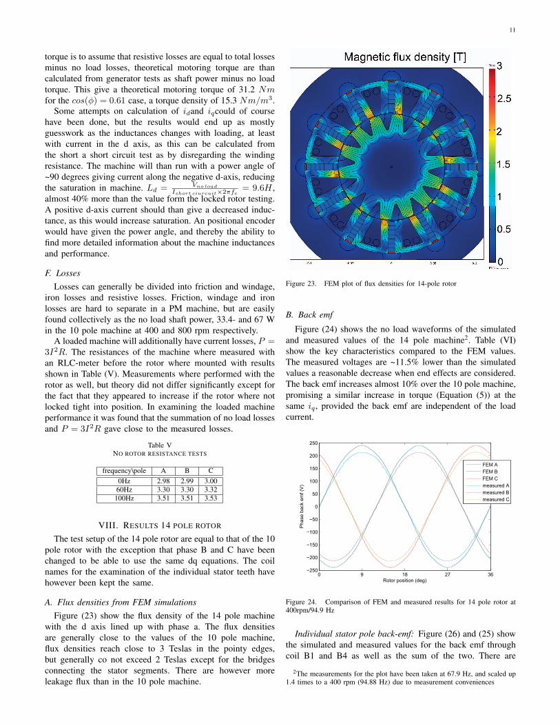
A. Flux densities from FEM simulationsFigure (23) show the flux density of the 14 pole machine
with the d axis lined up with phase a. The flux densitiesare generally close to the values of the 10 pole machine,flux densities reach close to 3 Teslas in the pointy edges,but generally co not exceed 2 Teslas except for the bridgesconnecting the stator segments. There are however moreleakage flux than in the 10 pole machine.
Figure 23. FEM plot of flux densities for 14-pole rotor
B. Back emf
Figure (24) shows the no load waveforms of the simulatedand measured values of the 14 pole machine2. Table (VI)show the key characteristics compared to the FEM values.The measured voltages are ~11.5% lower than the simulatedvalues a reasonable decrease when end effects are considered.The back emf increases almost 10% over the 10 pole machine,promising a similar increase in torque (Equation (5)) at thesame iq , provided the back emf are independent of the loadcurrent.
0 9 18 27 36−250
−200
−150
−100
−50
0
50
100
150
200
250
Rotor position (deg)
Pha
se b
ack
emf (
V)
FEM AFEM BFEM Cmeasured Ameasured Bmeasured C
Figure 24. Comparison of FEM and measured results for 14 pole rotor at400rpm/94.9 Hz
Individual stator pole back-emf: Figure (26) and (25) showthe simulated and measured values for the back emf throughcoil B1 and B4 as well as the sum of the two. There are
2The measurements for the plot have been taken at 67.9 Hz, and scaled up1.4 times to a 400 rpm (94.88 Hz) due to measurement conveniences

12
Table VIKEY RESULTS FROM 14 POLE ROTOR AT 94.9 HZ
Parameter FEM MeasuredVa peak 239.5 212.2Vb peak 239.5 210.9Vc peak 239.5 212.8THD a 1.1% 1.1%THD b 1.1% 0.9%THD c 1.1% 1.1%
apparently less difference between the back emf of coils herethan the case is for the 10 pole machine, the effect of thisdifference on machine performance would be interesting toexamine more closely. The back emf of the B1 measurementsis seen to be larger than that of B4 just as the case was withthe 10 pole machine, as expected from the air gap differences.
0 6.42857 12.8571 19.2857 25.7143
−0.6
−0.4
−0.2
0
0.2
0.4
0.6
Mechanical angle
Vol
t per
turn
Pole B1pole B4pole B1 + pole B4
Figure 25. Measurements of induced voltages for pole B1 and B4, with 14poled rotor at 400 rpm
0 6.42857 12.8571 19.2857 25.7143−0.8
−0.6
−0.4
−0.2
0
0.2
0.4
0.6
0.8
Rotor position (deg)
back
em
f per
turn
(V)
pole B1pole B4pole B1 & B4
Figure 26. FEM simulation of induced voltages for pole B1 and B4, with14 poled rotor at 400 rpm
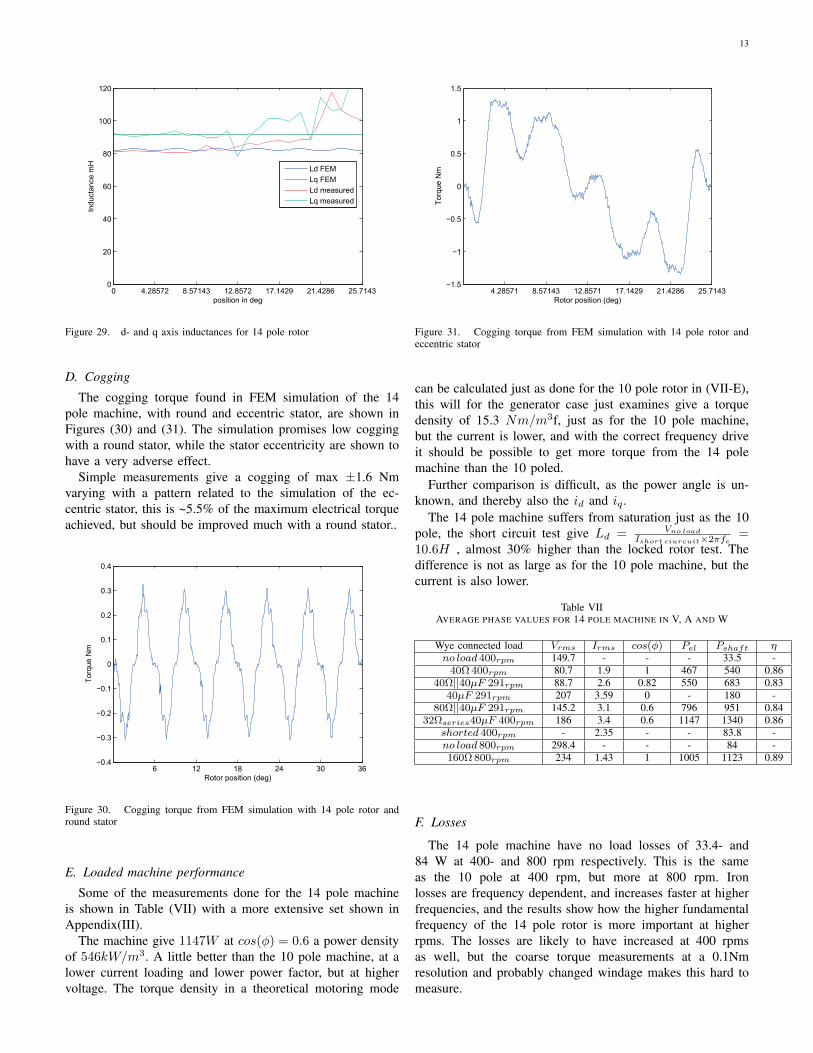
C. Inductances from locked rotor test
Figure (27) (28) and (29), with numbers listed in Appendix(VI and VII), show the self-, mutual- and dq inductances fromthe locked rotor testing of the machine. The measurementscoincide very well at first, but are seen to get weary strange asthe rotor angle increases. This have been identified as a currentclamp that gradually ran out of battery giving lower and lowercurrent measurements and hence higher inductance values arecalculated, there where not time to repeat the measurements,but the first part of the measurements are assumed to be correctand representative for the machine.
The inductances are seen ~15% larger than those of the 10pole machine, as should be expected with more steel in therotor. A much more important difference between the 10 and14 pole machine is that fe/rpm and thereby the reactanceper inductance is effectively 40% higher in the than in the 10pole machine. This is factor is important in the dimensioningof possible frequency drives and for the possibility of drivingthe machine in field weakening mode.
0 4.28572 8.57143 12.8572 17.1429 21.4286 25.71430
10
20
30
40
50
60
70
80
position in deg
Indu
ctan
ce m
H
FEM LaFEM LbFEM Lcmeasured Lameasured Lbmeasured Lc
Figure 27. Self inductances for 14 pole rotor
0 4.28572 8.57143 12.8572 17.1429 21.4286 25.7143−40
−35
−30
−25
−20
−15
−10
−5
0
position in deg
Indu
ctan
ce m
H
Mab FEMMac FEMMbc FEMMab measuredMac measuredMbc measured
Figure 28. Mutual inductances for 14 pole rotor
13
0 4.28572 8.57143 12.8572 17.1429 21.4286 25.71430
20
40
60
80
100
120
position in deg
Indu
ctan
ce m
H
Ld FEMLq FEMLd measuredLq measured
Figure 29. d- and q axis inductances for 14 pole rotor
D. Cogging
The cogging torque found in FEM simulation of the 14pole machine, with round and eccentric stator, are shown inFigures (30) and (31). The simulation promises low coggingwith a round stator, while the stator eccentricity are shown tohave a very adverse effect.
Simple measurements give a cogging of max ±1.6 Nmvarying with a pattern related to the simulation of the ec-centric stator, this is ~5.5% of the maximum electrical torqueachieved, but should be improved much with a round stator..
6 12 18 24 30 36−0.4
−0.3
−0.2
−0.1
0
0.1
0.2
0.3
0.4
Rotor position (deg)
Torq
ue N
m
Figure 30. Cogging torque from FEM simulation with 14 pole rotor andround stator
E. Loaded machine performance
Some of the measurements done for the 14 pole machineis shown in Table (VII) with a more extensive set shown inAppendix(III).
The machine give 1147W at cos(φ) = 0.6 a power densityof 546kW/m3. A little better than the 10 pole machine, at alower current loading and lower power factor, but at highervoltage. The torque density in a theoretical motoring mode
4.28571 8.57143 12.8571 17.1429 21.4286 25.7143−1.5
−1
−0.5
0
0.5
1
1.5
Rotor position (deg)
Torq
ue N
m
Figure 31. Cogging torque from FEM simulation with 14 pole rotor andeccentric stator
can be calculated just as done for the 10 pole rotor in (VII-E),this will for the generator case just examines give a torquedensity of 15.3 Nm/m3f, just as for the 10 pole machine,but the current is lower, and with the correct frequency driveit should be possible to get more torque from the 14 polemachine than the 10 poled.
Further comparison is difficult, as the power angle is un-known, and thereby also the id and iq .
The 14 pole machine suffers from saturation just as the 10pole, the short circuit test give Ld = Vno load
Ishort ciurcuit×2πfe=
10.6H , almost 30% higher than the locked rotor test. Thedifference is not as large as for the 10 pole machine, but thecurrent is also lower.
Table VIIAVERAGE PHASE VALUES FOR 14 POLE MACHINE IN V, A AND W
Wye connected load Vrms Irms cos(φ) Pel Pshaft ηno load 400rpm 149.7 - - - 33.5 -
40Ω 400rpm 80.7 1.9 1 467 540 0.8640Ω||40µF 291rpm 88.7 2.6 0.82 550 683 0.83
40µF 291rpm 207 3.59 0 - 180 -80Ω||40µF 291rpm 145.2 3.1 0.6 796 951 0.84
32Ωseries40µF 400rpm 186 3.4 0.6 1147 1340 0.86shorted 400rpm - 2.35 - - 83.8 -no load 800rpm 298.4 - - - 84 -160Ω 800rpm 234 1.43 1 1005 1123 0.89
F. Losses
The 14 pole machine have no load losses of 33.4- and84 W at 400- and 800 rpm respectively. This is the sameas the 10 pole at 400 rpm, but more at 800 rpm. Ironlosses are frequency dependent, and increases faster at higherfrequencies, and the results show how the higher fundamentalfrequency of the 14 pole rotor is more important at higherrpms. The losses are likely to have increased at 400 rpmsas well, but the coarse torque measurements at a 0.1Nmresolution and probably changed windage makes this hard tomeasure.

14
Resistance values from no rotor measurements are of coursethe same as for the 10 pole rotor, shown in Table (V). Mea-surements where performed with the rotor mounted, givingsimilar values as the no rotor case, but these where just as forthe 10 pole very dependent on how the rotor where lockedinto place. The summation of no load losses and P = 3I2Rgave close to the measured losses for the 14 pole machine,just as for the 10 pole, but this field needs to be examinedmore closely.
IX. FURTHER WORK
The machine should be tested with a frequency converterand a positional encoder. This would give the opportunity torun a pure q-axis current, giving a much better platform foran evaluation of the machine performance, both in terms oftorque density and in examining the saturation issues presentin the machine. A frequency converter would of course givethe opportunity to run the machine as a motor as well as agenerator.
Further work should also be put into the examination oflosses and resistances, with more detailed measurements ofthe torque, to get better values for both the generator inputpower and hence the losses, and the cogging torque.
The stator eccentricity show little effect on the phase volt-ages, but some work should still be put into the examinationof possible power fluctuation caused by this.
Still another task that can be performed are the testing ofalternative rotors, such as skewing the rotors already made andtesting of a more optimized 14 pole rotor
X. CONCLUSION
The FSPM machine concept have been studied, and a FSPMmachine with a 12 pole stator and an interchangeable rotorof 10 and 14 poles have been built. The machine have beentested as a generator, with various resistive and capacitiveloads, while locked rotor tests have been performed to plotthe machine inductances as a function of rotor position, givingresults close to the values found by FEM analysis. Both rotorconfigurations run smoothly with THD of less than 1.4% inno load and little more while loaded.
The 10- and 14 pole rotor have a measured 400 rpm phaseback emf, of 136.3V and 149.7V rms respectively, giving the14 pole a torque constant approximately 10% higher than thatof the 10 pole. The load tests of both machines show a peakelectrical power at 400rpm of ~1150W with a power densityof ~540kW/m3 at η~85%. The 14 pole rotor seems to bebetter than the 10 pole rotor, but comparison of the loadedmachine performance is difficult without better control the thed- and q axis currents, especially as saturation issues causesthe machine inductances to vary much with machine loading.
The machine stator where made with a slight eccentricitycausing the air gap to vary from 0.8mm to 1.2mm, This isbelieved to have increased cogging, but does not seem to haveeffected the machine phase- voltages and currents much, asthese keep within 2-3% each other at the tested loads.
ACKNOWLEDGMENTS
I would like to thank my supervisor Robert Nilssen for theopportunity to design and build a my own electric machine,Anyuan Chen for always taking time to answer my questionsand Oddvar Landrø at the workshop, for great help with thepractical building of the machine.
REFERENCES
[1] W. Hua, M. Cheng, H. Jia, and X. Fu, “Comparative Study of Flux-Switching and Doubly-Salient PM Machines Particularly on TorqueCapability,” in IEEE Industry Applications Society Annual Meeting,2008. IAS’08, 2008, pp. 1–8.
[2] C. Wang, S. Nasar, and I. Boldea, “Three-phase flux reversal machine(FRM),” IEE Proceedings-Electric Power Applications, vol. 146, p. 139,1999.
[3] S. Rauch, L. Johnson, N. AIEE, and C. Santa Barbara, “"Designprinciples of flux-switch alternators",” Power Apparatus and Systems,Part III. Transactions of the American Institute of Electrical Engineers,vol. 74, no. 3 Part III, pp. 1261–1268, 1955.
[4] E. Hoang, A. Ben Ahmed, and J. Lucidarme, “Switching flux per-manent magnet polyphased synchronous machines,” in EUROPEANCONFERENCE ON POWER ELECTRONICS AND APPLICATIONS,vol. 3. PROCEEDINGS PUBLISHED BY VARIOUS PUBLISHERS,1997, pp. 3–3.
[5] J. Chen, Z. Zhu, and D. Howe, “Stator and Rotor Pole Combinationsfor Multi-Tooth Flux-Switching Permanent-Magnet Brushless AC Ma-chines,” IEEE Transactions on Magnetics, vol. 44, no. 12, pp. 4659–4667, 2008.
[6] Z. Zhu, J. Chen, Y. Pang, D. Howe, S. Iwasaki, and R. Deodhar,“Analysis of a Novel Multi-Tooth Flux-Switching PM Brushless ACMachine for High Torque Direct-Drive Applications,” IEEE Transactionson Magnetics, vol. 44, no. 11 Part 2, pp. 4313–4316, 2008.
[7] “Parallel path magnetic technology for high efficiency power genera-tors and motor drives,” http://www.flynnresearch.net/technology/PPMTtechnology white paper.pdf.
[8] J. Wang, W. Wang, K. Atallah, and D. Howe, “Design Considerationsfor Tubular Flux-Switching Permanent Magnet Machines,” IEEE Trans-actions on Magnetics, vol. 44, no. 11 Part 2, pp. 4026–4032, 2008.
[9] H. Pollock, C. Pollock, R. Walter, and B. Gorti, “Low cost, high powerdensity, flux switching machines and drives for power tools,” in IndustryApplications Conference, 2003. 38th IAS Annual Meeting. ConferenceRecord of the, vol. 3, 2003.
[10] A. Thomas, Z. Zhu, G. Jewell, and D. Howe, “Flux-switching PMbrushless machines with alternative stator and rotor pole combinations,”in Electrical Machines and Systems, 2008. ICEMS 2008. InternationalConference on, 2008, pp. 2986–2991.
[11] W. Fei and J. Shen, “Comparative Study and Optimal Design of PMSwitching Flux Motors,” in Universities Power Engineering Conference,2006. UPEC’06. Proceedings of the 41st International, vol. 2, 2006.
[12] J. Chen, Z. Zhu, A. Thomas, and D. Howe, “Optimal combinationof stator and rotor pole numbers in flux-switching PM brushless ACmachines,” in Electrical Machines and Systems, 2008. ICEMS 2008.International Conference on, 2008, pp. 2905–2910.
[13] W. Fei and J. Shen, “Comparative study and optimal design of pmswitching flux motors,” vol. 2, Sept. 2006, pp. 695–699.
[14] Z. Zhu, Y. Pang, D. Howe, S. Iwasaki, R. Deodhar, and A. Pride,“Analysis of electromagnetic performance of flux-switching permanent-magnet machines by nonlinear adaptive lumped parameter magneticcircuit model,” IEEE Transactions on magnetics, vol. 41, no. 11, pp.4277–4287, 2005.
[15] Z. Zhu, Y. Pang, J. Chen, Z. Xia, and D. Howe, “Influence of de-sign parameters on output torque of flux-switching permanent magnetmachines,” in IEEE Vehicle Power and Propulsion Conference, 2008.VPPC’08, 2008, pp. 1–6.
[16] W. Hua, M. Cheng, Z. Zhu, and D. Howe, “Analysis and Optimizationof Back-EMF Waveform of a Novel Flux-Switching Permanent MagnetMotor,” in IEEE International Electric Machines & Drives Conference,2007. IEMDC’07, vol. 2, 2007.

Appendix I Lumped parameter model %Function modeling FSPM machines of any rotor/stator tooth combination by the %use of air gap permeances. %The machines are modelled with infinitely permeable stator- and rotor steel %while air gap permeances are modelled withour any fringing effects. %s_teeth=12; %number of stator poles %s_scaling=1.0; %scaling factor of stator teeth vs base tooth width % %r_teeth=10; %number of rotor teeth %r_scaling=1.4; %scaling factor of rotor teeth vs base tooth width % %base=15e-3; %base tooth with (width of rotor and stator teeth, magnets and winding slots) %m_length=2; %machine length in #base %airgap=1e-3; %air gap length %magnet_length=base*3; %length of magnets radially %Br=1.2; %magnent remanance flux %tann %avreage flux density in stator tooth number one %coil %coil(#,x)= flux in tooth # for step number x; function [coil tann] = fluxs2... (s_teeth,r_teeth,s_scaling,r_scaling,airgap,base,m_length,magnet_length,Br) my_0=4*pi*1e-7; %my0 Am=(magnet_length)*(base*m_length);%magnet area lm=base*(2-s_scaling); %magnet length Ym=my_0*Am/lm; %magnet permeability phi_r=Br*Am; stator=0:base*2:base*(4*(s_teeth)-1); %middle of stator teeth O=base*4*s_teeth; base_rotor=-O/r_teeth:O/r_teeth:O/r_teeth*r_teeth; %middle if rotor teeth min_slot=min(base*[r_scaling s_scaling]); %the smallest tooth width step=0;

for displasement=0:0.02*base:O/r_teeth-0.02*base %moving the rotor step=step+1; rotor=base_rotor+displasement; i=0; Y=inf(1,length(stator)); for s_tooth=stator i=i+1; gap_w=0; for r_tooth=rotor %calculation of stator/rotor air gap width for use in reluctance calculations tmp=abs(s_tooth-r_tooth)-base*abs(r_scaling-s_scaling)/2; if tmp<0 gap_w=min_slot; elseif tmp<min_slot gap_w=min_slot-tmp; end end R_air=airgap/(gap_w*base*m_length*my_0); Y(i)=1/R_air; %admittance of different stator/rotor air gaps end %setting up Y matrix for counter=2:(length(Y)/2-1) Ymat(counter,counter)=Y(2*counter-1)+Y(2*counter)+2*Ym; Ymat(counter,counter+1)=-Ym; Ymat(counter,counter-1)=-Ym; end Ymat(1,1)=Y(2*1-1)+Y(2*1)+2*Ym; Ymat(1,1+1)=-Ym; Ymat(length(Y)/2,length(Y)/2)=Y(length(Y)-1)+Y(length(Y))+2*Ym; Ymat(length(Y)/2,length(Y)/2-1)=-Ym; Ymat(1,length(Y)/2)=-Ym; Ymat(length(Y)/2,1)=-Ym; %setting up magnet flux sources for counter=1:length(Ymat) phi(counter,1)=-(-1)^counter*2*phi_r; end %solving the matix equations equations: Um=inv(Ymat)*phi; %Um=magnetisk potensiale; for i=1:length(Ymat)-1 %calculating coil flux linkeages coil(i,step)=Um(i)*Y(i*2)+Um(i+1)*Y(i*2+1); end coil(length(Ymat),step)=Um(length(Ymat))*Y(length(Ymat)*2)+Y(1)*Um(1); tann(step)=Um(1)*Y(1)/(base^2*m_length*s_scaling); % avreage flux density in stator tooth number one end
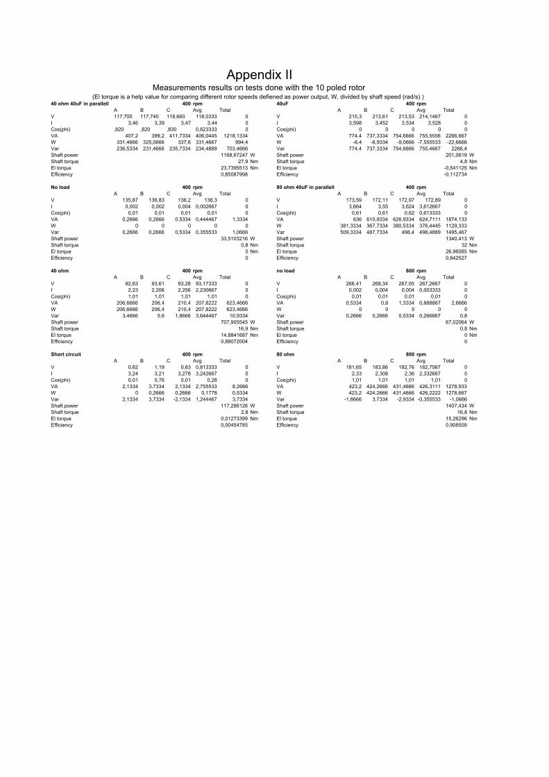
40 ohm 40uF in parallell 27,9 Nm 400 rpm 40uF 4,8 Nm 400 rpmA B C Avg Total A B C Avg Total
V 117,700 117,740 118,660 118,0333 0 V 215,3 213,61 213,53 214,1467 0I 3,46 3,39 3,47 3,44 0 I 3,598 3,452 3,534 3,528 0Cos(phi) ,820 ,820 ,830 0,823333 0 Cos(phi) 0 0 0 0 0VA 407,2 399,2 411,7334 406,0445 1218,1334 VA 774,4 737,3334 754,6666 755,5556 2266,667W 331,4666 325,0666 337,6 331,4667 994,4 W -6,4 -6,9334 -9,0666 -7,555533 -22,6666Var 236,5334 231,4666 235,7334 234,4889 703,4666 Var 774,4 737,3334 754,6666 755,4667 2266,4Shaft power 1168,67247 W Shaft power 201,0619 WShaft torque 27,9 Nm Shaft torque 4,8 NmEl torque 23,7395513 Nm El torque -0,541125 NmEfficiency 0,85087998 Efficiency -0,112734
No load 0,8 Nm 400 rpm 80 ohm 40uF in parallell 32 Nm 400 rpmA B C Avg Total A B C Avg Total
V 135,87 136,83 136,2 136,3 0 V 173,59 172,11 172,97 172,89 0I 0,002 0,002 0,004 0,002667 0 I 3,664 3,55 3,624 3,612667 0Cos(phi) 0,01 0,01 0,01 0,01 0 Cos(phi) 0,61 0,61 0,62 0,613333 0VA 0,2666 0,2666 0,5334 0,444467 1,3334 VA 636 610,9334 626,9334 624,7111 1874,133W 0 0 0 0 0 W 381,3334 367,7334 380,5334 376,4445 1129,333Var 0,2666 0,2666 0,5334 0,355533 1,0666 Var 509,3334 487,7334 498,4 498,4889 1495,467Shaft power 33,5103216 W Shaft power 1340,413 WShaft torque 0,8 Nm Shaft torque 32 NmEl torque 0 Nm El torque 26,96085 NmEfficiency 0 Efficiency 0,842527
40 ohm 16,9 Nm 400 rpm no load 0,8 Nm 800 rpmA B C Avg Total A B C Avg Total
V 92,63 93,61 93,28 93,17333 0 V 266,41 268,34 267,05 267,2667 0I 2,23 2,206 2,256 2,230667 0 I 0,002 0,004 0,004 0,003333 0Cos(phi) 1,01 1,01 1,01 1,01 0 Cos(phi) 0,01 0,01 0,01 0,01 0VA 206,6666 206,4 210,4 207,8222 623,4666 VA 0,5334 0,8 1,3334 0,888867 2,6666W 206,6666 206,4 210,4 207,8222 623,4666 W 0 0 0 0 0Var 3,4666 5,6 1,8666 3,644467 10,9334 Var 0,2666 0,2666 0,5334 0,266667 0,8Shaft power 707,905545 W Shaft power 67,02064 WShaft torque 16,9 Nm Shaft torque 0,8 NmEl torque 14,8841687 Nm El torque 0 NmEfficiency 0,88072004 Efficiency 0
Short circuit 2,8 Nm 400 rpm 80 ohm 16,8 Nm 800 rpmA B C Avg Total A B C Avg Total
V 0,62 1,19 0,63 0,813333 0 V 181,65 183,86 182,76 182,7567 0I 3,24 3,21 3,278 3,242667 0 I 2,33 2,308 2,36 2,332667 0Cos(phi) 0,01 0,76 0,01 0,26 0 Cos(phi) 1,01 1,01 1,01 1,01 0VA 2,1334 3,7334 2,1334 2,755533 8,2666 VA 423,2 424,2666 431,4666 426,3111 1278,933W 0 0,2666 0,2666 0,1778 0,5334 W 423,2 424,2666 431,4666 426,2222 1278,667Var 2,1334 3,7334 -2,1334 1,244467 3,7334 Var -1,8666 3,7334 -2,9334 -0,355533 -1,0666Shaft power 117,286126 W Shaft power 1407,434 WShaft torque 2,8 Nm Shaft torque 16,8 NmEl torque 0,01273399 Nm El torque 15,26296 NmEfficiency 0,00454785 Efficiency 0,908509
Appendix IIMeasurements results on tests done with the 10 poled rotor
(El torque is a help value for comparing different rotor speeds defiened as power output, W, divided by shaft speed (rad/s) )
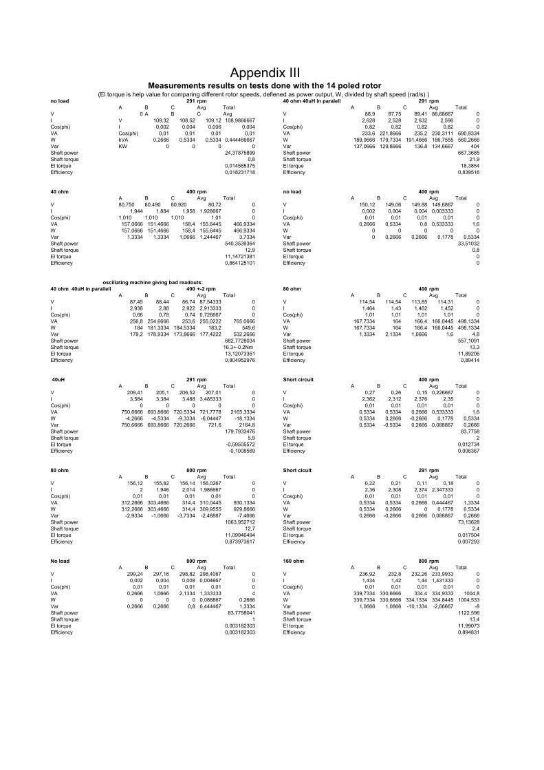
no load 0,8 Nm 291 rpm 40 ohm 40uH in paralell 21,9 Nm 291 rpmA B C Avg Total A B C Avg Total
V 0 A B C Avg V 88,9 87,75 89,41 88,68667 0I V 109,32 108,52 109,12 108,9866667 I 2,628 2,528 2,632 2,596 0Cos(phi) I 0,002 0,004 0,006 0,004 Cos(phi) 0,82 0,82 0,82 0,82 0VA Cos(phi) 0,01 0,01 0,01 0,01 VA 233,6 221,8666 235,2 230,3111 690,9334W kVA 0,2666 0,5334 0,5334 0,444466667 W 189,0666 179,7334 191,4666 186,7555 560,2666Var KW 0 0 0 0 Var 137,0666 129,8666 136,8 134,6667 404Shaft power 24,37875899 Shaft power 667,3685Shaft torque 0,8 Shaft torque 21,9El torque 0,014585375 El torque 18,3854Efficiency 0,018231718 Efficiency 0,839516
40 ohm 12,9 Nm 400 rpm no load 0,8 Nm 400 rpmA B C Avg Total A B C Avg Total
V 80,750 80,490 80,920 80,72 0 V 150,12 149,06 149,88 149,6867 0I 1,944 1,884 1,958 1,928667 0 I 0,002 0,004 0,004 0,003333 0Cos(phi) 1,010 1,010 1,010 1,01 0 Cos(phi) 0,01 0,01 0,01 0,01 0VA 157,0666 151,4666 158,4 155,6445 466,9334 VA 0,2666 0,5334 0,8 0,533333 1,6W 157,0666 151,4666 158,4 155,6445 466,9334 W 0 0 0 0 0Var 1,3334 1,3334 1,0666 1,244467 3,7334 Var 0 0,2666 0,2666 0,1778 0,5334Shaft power 540,3539364 Shaft power 33,51032Shaft torque 12,9 Shaft torque 0,8El torque 11,14721381 El torque 0Efficiency 0,864125101 Efficiency 0
40 ohm 40uH in parallell 16,3 +- 0.2 Nm 400 +-2 rpm 80 ohm 13,3 Nm 400 rpmA B C Avg Total A B C Avg Total
V 87,45 88,44 86,74 87,54333 0 V 114,54 114,54 113,85 114,31 0I 2,938 2,88 2,922 2,913333 0 I 1,464 1,43 1,462 1,452 0Cos(phi) 0,66 0,78 0,74 0,726667 0 Cos(phi) 1,01 1,01 1,01 1,01 0VA 256,8 254,6666 253,6 255,0222 765,0666 VA 167,7334 164 166,4 166,0445 498,1334W 184 181,3334 184,5334 183,2 549,6 W 167,7334 164 166,4 166,0445 498,1334Var 179,2 178,9334 173,8666 177,4222 532,2666 Var 1,3334 2,1334 1,0666 1,6 4,8Shaft power 682,7728034 Shaft power 557,1091Shaft torque 16.3+-0.2Nm Shaft torque 13,3El torque 13,12073351 El torque 11,89206Efficiency 0,804952976 Efficiency 0,89414
40uH 5,9 Nm 291 rpm Short circuit 2 Nm 400 rpmA B C Avg Total A B C Avg Total
V 209,41 205,1 206,52 207,01 0 V 0,27 0,26 0,15 0,226667 0I 3,584 3,384 3,488 3,485333 0 I 2,362 2,312 2,376 2,35 0Cos(phi) 0 0 0 0 0 Cos(phi) 0,01 0,01 0,01 0,01 0VA 750,6666 693,8666 720,5334 721,7778 2165,3334 VA 0,5334 0,5334 0,2666 0,533333 1,6W -4,2666 -4,5334 -9,3334 -6,04447 -18,1334 W 0,5334 0,2666 -0,2666 0,1778 0,5334Var 750,6666 693,8666 720,2666 721,6 2164,8 Var 0,5334 -0,5334 0,2666 0,088867 0,2666Shaft power 179,7933476 Shaft power 83,7758Shaft torque 5,9 Shaft torque 2El torque -0,59505572 El torque 0,012734Efficiency -0,1008569 Efficiency 0,006367
80 ohm 12,7 Nm 800 rpm Short cicuit 2,4 Nm 291 rpmA B C Avg Total A B C Avg Total
V 156,12 155,82 156,14 156,0267 0 V 0,22 0,21 0,11 0,18 0I 2 1,946 2,014 1,986667 0 I 2,36 2,308 2,374 2,347333 0Cos(phi) 0,01 0,01 0,01 0,01 0 Cos(phi) 0,01 0,01 0,01 0,01 0VA 312,2666 303,4666 314,4 310,0445 930,1334 VA 0,5334 0,5334 0,2666 0,444467 1,3334W 312,2666 303,4666 314,4 309,9555 929,8666 W 0,5334 0,2666 0 0,1778 0,5334Var -2,9334 -1,0666 -3,7334 -2,48887 -7,4666 Var 0,2666 -0,2666 0,2666 0,088867 0,2666Shaft power 1063,952712 Shaft power 73,13628Shaft torque 12,7 Shaft torque 2,4El torque 11,09946494 El torque 0,017504Efficiency 0,873973617 Efficiency 0,007293
No load 1 Nm 800 rpm 160 ohm 13,4 Nm 800 rpmA B C Avg Total A B C Avg Total
V 299,24 297,16 298,82 298,4067 0 V 236,92 232,8 232,26 233,9933 0I 0,002 0,004 0,008 0,004667 0 I 1,434 1,42 1,44 1,431333 0Cos(phi) 0,01 0,01 0,01 0,01 0 Cos(phi) 0,01 0,01 0,01 0,01 0VA 0,2666 1,0666 2,1334 1,333333 4 VA 339,7334 330,6666 334,4 334,9333 1004,8W 0 0 0 0,088867 0,2666 W 339,7334 330,6666 334,1334 334,8445 1004,533Var 0,2666 0,2666 0,8 0,444467 1,3334 Var 1,0666 1,0666 -10,1334 -2,66667 -8Shaft power 83,7758041 Shaft power 1122,596Shaft torque 1 Shaft torque 13,4El torque 0,003182303 El torque 11,99073Efficiency 0,003182303 Efficiency 0,894831
oscillating machine giving bad readouts:
Appendix IIIMeasurements results on tests done with the 14 poled rotor
(El torque is help value for comparing different rotor speeds, defiened as power output, W, divided by shaft speed (rad/s) )

80 ohm 40uH in paralell 31,2 Nm 291 rpm 32 ohm 40uH in series 32 Nm 400 rpmA B C Avg Total A B C Avg Total
V 146,48 143 146,22 145,2333 0 V 184,6 185,69 188,02 186,1033 0I 3,134 2,976 3,1 3,07 0 I 3,398 3,328 3,468 3,398 0Cos(phi) 0,6 0,61 0,61 0,606667 0 Cos(phi) 0,6 0,6 0,59 0,596667 0VA 458,9334 425,6 453,0666 445,8667 1337,6 VA 627,4666 617,8666 652 632,5333 1897,6W 272,2666 253,3334 270,6666 265,3333 796 W 382,9334 372,2666 392,5334 382,5778 1147,733Var 369,3334 342,1334 363,4666 358,2222 1074,6666 Var 496,8 493,0666 520,8 503,5555 1510,667Shaft power 950,7716007 Shaft power 1340,413Shaft torque 31,2 Shaft torque 32El torque 26,12109994 El torque 27,40012Efficiency 0,837214742 Efficiency 0,856254
40 ohm 40uH in series 28,7 Nm 400 rpm 80 ohm 40uH in series 18,9 Nm 400 rpmA B C Avg Total A B C Avg Total
V 174,15 174,43 177,06 175,2133 0 V 156,22 155,74 157,07 156,3433 0I 2,914 2,836 2,962 2,904 0 I 1,752 1,704 1,768 1,741333 0Cos(phi) 0,69 0,68 0,68 0,683333 0 Cos(phi) 0,88 0,87 0,87 0,873333 0VA 507,2 494,6666 524,2666 508,8 1526,4 VA 273,6 265,3334 277,8666 272,2667 816,8W 352,5334 340,8 360,2666 351,1111 1053,3334 W 239,2 230,6666 241,8666 237,2445 711,7334Var 364,8 358,4 381,0666 368,1778 1104,5334 Var 132,8 131,2 136,5334 133,6 400,8Shaft power 1202,182789 Shaft power 791,6813Shaft torque 28,7 Shaft torque 18,9El torque 25,1464826 El torque 16,99138Efficiency 0,876184063 Efficiency 0,899015
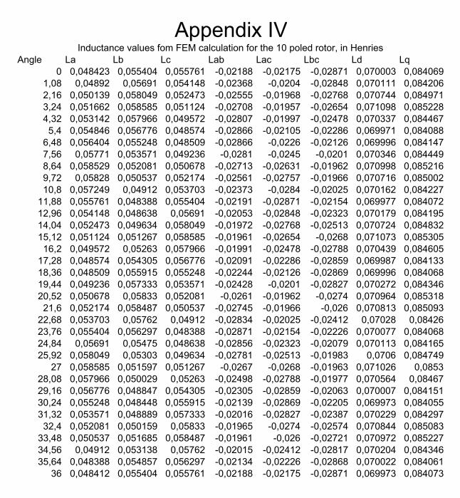
Angle La Lb Lc Lab Lac Lbc Ld Lq0 0,048423 0,055404 0,055761 -0,02188 -0,02175 -0,02871 0,070003 0,084069
1,08 0,04892 0,05691 0,054148 -0,02368 -0,0204 -0,02848 0,070111 0,0842062,16 0,050139 0,058049 0,052473 -0,02555 -0,01968 -0,02768 0,070744 0,0849713,24 0,051662 0,058585 0,051124 -0,02708 -0,01957 -0,02654 0,071098 0,0852284,32 0,053142 0,057966 0,049572 -0,02807 -0,01997 -0,02478 0,070337 0,0844675,4 0,054846 0,056776 0,048574 -0,02866 -0,02105 -0,02286 0,069971 0,084088
6,48 0,056404 0,055248 0,048509 -0,02866 -0,0226 -0,02126 0,069996 0,0841477,56 0,05771 0,053571 0,049236 -0,0281 -0,0245 -0,0201 0,070346 0,0844498,64 0,058529 0,052081 0,050678 -0,02713 -0,02631 -0,01962 0,070998 0,0852169,72 0,05828 0,050537 0,052174 -0,02561 -0,02757 -0,01966 0,070716 0,08500210,8 0,057249 0,04912 0,053703 -0,02373 -0,0284 -0,02025 0,070162 0,084227
11,88 0,055761 0,048388 0,055404 -0,02191 -0,02871 -0,02154 0,069977 0,08407212,96 0,054148 0,048638 0,05691 -0,02053 -0,02848 -0,02323 0,070179 0,08419514,04 0,052473 0,049634 0,058049 -0,01972 -0,02768 -0,02513 0,070724 0,08483215,12 0,051124 0,051267 0,058585 -0,01961 -0,02654 -0,0268 0,071073 0,08530516,2 0,049572 0,05263 0,057966 -0,01991 -0,02478 -0,02788 0,070439 0,084605
17,28 0,048574 0,054305 0,056776 -0,02091 -0,02286 -0,02859 0,069987 0,08413318,36 0,048509 0,055915 0,055248 -0,02244 -0,02126 -0,02869 0,069996 0,08406819,44 0,049236 0,057333 0,053571 -0,02428 -0,0201 -0,02827 0,070272 0,08434620,52 0,050678 0,05833 0,052081 -0,0261 -0,01962 -0,0274 0,070964 0,08531821,6 0,052174 0,058487 0,050537 -0,02745 -0,01966 -0,026 0,070813 0,085093
22,68 0,053703 0,05762 0,04912 -0,02834 -0,02025 -0,02412 0,07028 0,0842623,76 0,055404 0,056297 0,048388 -0,02871 -0,02154 -0,02226 0,070077 0,08406824,84 0,05691 0,05475 0,048638 -0,02856 -0,02323 -0,02079 0,070113 0,08416525,92 0,058049 0,05303 0,049634 -0,02781 -0,02513 -0,01983 0,0706 0,084749
27 0,058585 0,051597 0,051267 -0,0267 -0,0268 -0,01963 0,071026 0,085328,08 0,057966 0,050029 0,05263 -0,02498 -0,02788 -0,01977 0,070564 0,0846729,16 0,056776 0,048847 0,054305 -0,02305 -0,02859 -0,02063 0,070007 0,08415130,24 0,055248 0,048448 0,055915 -0,02139 -0,02869 -0,02205 0,069973 0,08405531,32 0,053571 0,048889 0,057333 -0,02016 -0,02827 -0,02387 0,070229 0,08429732,4 0,052081 0,050159 0,05833 -0,01965 -0,0274 -0,02574 0,070844 0,085083
33,48 0,050537 0,051685 0,058487 -0,01961 -0,026 -0,02721 0,070972 0,08522734,56 0,04912 0,053138 0,05762 -0,02015 -0,02412 -0,02817 0,070204 0,08434635,64 0,048388 0,054857 0,056297 -0,02134 -0,02226 -0,02868 0,070022 0,084061
36 0,048412 0,055404 0,055761 -0,02188 -0,02175 -0,02871 0,069973 0,084073
Appendix IVInductance values fom FEM calculation for the 10 poled rotor, in Henries

Angle Ra Rb Rc La Lb Lc Lab Lac Lba Lbc Lca Lcb Ld Lq0 3,546456 3,91056 3,91056 0,047893 0,05281 0,05281 -0,02116 -0,02134 -0,02095 -0,02592 -0,02112 -0,02592 0,06908 0,07873
1,5 3,597485 4,065946 3,858764 0,048582 0,054908 0,05211 -0,02309 -0,01994 -0,0229 -0,02556 -0,02006 -0,02592 0,06964 0,079923 3,699541 4,117741 3,674027 0,049908 0,055517 0,049535 -0,02481 -0,01939 -0,02447 -0,02447 -0,01939 -0,02481 0,06911 0,07997
4,5 3,829967 4,065946 3,57197 0,051599 0,054778 0,048123 -0,02566 -0,01986 -0,02568 -0,02285 -0,01989 -0,02303 0,06906 0,07966 3,962355 3,962355 3,546456 0,053351 0,053422 0,047815 -0,0262 -0,02089 -0,02602 -0,02106 -0,02075 -0,02127 0,06896 0,07949
7,5 4,01415 3,829967 3,597485 0,054008 0,051568 0,048402 -0,02565 -0,02246 -0,02563 -0,02001 -0,02265 -0,02004 0,06921 0,078929 4,065946 3,699541 3,699541 0,054746 0,049775 0,049775 -0,02443 -0,02425 -0,02441 -0,0197 -0,02441 -0,01988 0,06957 0,07899
10,5 4,065946 3,597485 3,829967 0,054705 0,048402 0,05153 -0,02282 -0,02565 -0,023 -0,02021 -0,02563 -0,02001 0,06942 0,0794412 3,988253 3,597485 3,962355 0,05366 0,048374 0,053311 -0,0214 -0,02618 -0,02126 -0,02126 -0,02618 -0,02122 0,06973 0,07966
13,5 3,91056 3,648513 4,01415 0,052583 0,049089 0,054008 -0,0205 -0,02563 -0,02055 -0,02299 -0,02545 -0,02298 0,07059 0,0792315 3,750569 3,750569 4,065946 0,050395 0,050432 0,054632 -0,02001 -0,02436 -0,02001 -0,02471 -0,02455 -0,0242 0,07042 0,07916
16,5 3,648513 3,91056 4,01415 0,049024 0,052545 0,053937 -0,02053 -0,02262 -0,02084 -0,02579 -0,02278 -0,02561 0,07055 0,0791818 3,648513 4,01415 3,962355 0,049024 0,053976 0,053241 -0,02193 -0,02123 -0,02173 -0,02596 -0,02137 -0,02614 0,07062 0,07966
19,5 3,699541 4,065946 3,829967 0,049709 0,054632 0,051462 -0,02332 -0,02053 -0,02331 -0,02596 -0,02069 -0,02542 0,07079 0,079521 3,829967 4,065946 3,699541 0,051462 0,054632 0,049709 -0,02507 -0,02034 -0,0249 -0,02384 -0,02019 -0,02401 0,07085 0,07914
22,5 3,962355 4,01415 3,597485 0,053241 0,053937 0,048302 -0,02596 -0,02084 -0,02579 -0,0219 -0,02106 -0,0221 0,0703 0,0792424 4,01415 3,962355 3,57197 0,053937 0,053241 0,047995 -0,02614 -0,02137 -0,02614 -0,02102 -0,02123 -0,02123 0,06943 0,07973
25,5 4,065946 3,829967 3,597485 0,054592 0,051462 0,048302 -0,02559 -0,02277 -0,02575 -0,01997 -0,02295 -0,02 0,06919 0,0793927 4,091844 3,699541 3,674027 0,05494 0,049673 0,04933 -0,02453 -0,02418 -0,02469 -0,0193 -0,02434 -0,01947 0,06889 0,07925
28,5 4,065946 3,597485 3,778558 0,054592 0,048302 0,050704 -0,02294 -0,02524 -0,02313 -0,01982 -0,0254 -0,0198 0,06892 0,0789230 3,988253 3,546456 3,962355 0,053549 0,047617 0,053201 -0,02136 -0,02612 -0,02139 -0,02069 -0,02612 -0,02083 0,06892 0,0795
31,5 3,91056 3,597485 4,01415 0,052506 0,048302 0,053897 -0,02012 -0,02612 -0,02 -0,02243 -0,02577 -0,02224 0,06933 0,0793633 3,750569 3,674027 4,091844 0,050358 0,04933 0,05494 -0,01982 -0,02469 -0,01965 -0,024 -0,02471 -0,02418 0,06958 0,07919
34,5 3,648513 3,829967 4,065946 0,048987 0,051424 0,054592 -0,02 -0,02347 -0,01997 -0,0254 -0,0233 -0,02506 0,06989 0,0791836 3,597485 3,962355 3,962355 0,048302 0,053201 0,053201 -0,02121 -0,02121 -0,02118 -0,02612 -0,02136 -0,02612 0,06955 0,07932
Locked rotor measurement results for 10 poled rotor, results in ohm and Henries
Appendix V
Angle La Lb Lc Lab Lac Lbc Ld Lq0 0,056047 0,061087 0,061043 -0,0255 -0,025483 -0,030482 0,081722 0,091752
0,714286 0,056382 0,061878 0,060395 -0,026426 -0,024883 -0,030424 0,082111 0,0919231,428571 0,057254 0,062597 0,05972 -0,027545 -0,024641 -0,029986 0,082773 0,0919472,142857 0,058591 0,062839 0,058676 -0,028885 -0,024646 -0,028937 0,083204 0,0918012,857143 0,059732 0,062554 0,057302 -0,029987 -0,024659 -0,027556 0,082727 0,0919373,571429 0,060375 0,061959 0,05631 -0,030422 -0,024865 -0,026386 0,082062 0,0918444,285714 0,061024 0,061032 0,056059 -0,030448 -0,0255 -0,025494 0,081739 0,091716
5 0,061949 0,060326 0,056352 -0,030432 -0,026438 -0,024884 0,082107 0,091895,714286 0,062628 0,05975 0,05726 -0,029994 -0,027552 -0,024645 0,082793 0,0919416,428571 0,062829 0,058704 0,0586 -0,028896 -0,028881 -0,024656 0,083365 0,091877,142857 0,062557 0,057282 0,059788 -0,027523 -0,029962 -0,024674 0,082879 0,0920517,857143 0,061876 0,05636 0,060403 -0,0264 -0,030399 -0,02488 0,082048 0,0918228,571429 0,061043 0,056047 0,061087 -0,025492 -0,030482 -0,025503 0,081768 0,0916699,285714 0,060395 0,056382 0,061878 -0,02488 -0,030424 -0,026393 0,081998 0,091907
10 0,05972 0,057254 0,062597 -0,024653 -0,029986 -0,027551 0,082888 0,09193810,71429 0,058676 0,058591 0,062839 -0,024659 -0,028937 -0,028886 0,083273 0,09180611,42857 0,057302 0,059732 0,062554 -0,024672 -0,027556 -0,029967 0,082734 0,09194912,14286 0,05631 0,060375 0,061959 -0,024867 -0,026386 -0,03045 0,082085 0,09190812,85714 0,056059 0,061024 0,061032 -0,0255 -0,025494 -0,030463 0,081746 0,09175913,57143 0,056352 0,061949 0,060326 -0,026409 -0,024884 -0,030403 0,082177 0,09191714,28571 0,05726 0,062628 0,05975 -0,027549 -0,024645 -0,030007 0,082895 0,091911
15 0,0586 0,062829 0,058704 -0,028895 -0,024656 -0,028936 0,083305 0,09174115,71429 0,059788 0,062557 0,057282 -0,030024 -0,024674 -0,027549 0,082787 0,09190316,42857 0,060403 0,061876 0,05636 -0,030433 -0,02488 -0,026402 0,082014 0,09185117,14286 0,061087 0,061043 0,056047 -0,030492 -0,025503 -0,025483 0,081748 0,09170817,85714 0,061878 0,060395 0,056382 -0,0304 -0,026393 -0,024883 0,082281 0,09187818,57143 0,062597 0,05972 0,057254 -0,029972 -0,027551 -0,024641 0,082869 0,09196619,28571 0,062839 0,058676 0,058591 -0,028901 -0,028886 -0,024646 0,083431 0,091839
20 0,062554 0,057302 0,059732 -0,027523 -0,029967 -0,024659 0,082785 0,09191420,71429 0,061959 0,05631 0,060375 -0,026415 -0,03045 -0,024865 0,082066 0,09181921,42857 0,061032 0,056059 0,061024 -0,025488 -0,030463 -0,0255 0,081658 0,09172822,14286 0,060326 0,056352 0,061949 -0,024864 -0,030403 -0,026438 0,081974 0,09190422,85714 0,05975 0,05726 0,062628 -0,024657 -0,030007 -0,027552 0,082758 0,09192423,57143 0,058704 0,0586 0,062829 -0,024686 -0,028936 -0,028881 0,083262 0,09177624,28571 0,057282 0,059788 0,062557 -0,024658 -0,027549 -0,029962 0,082773 0,091941
25 0,05636 0,060403 0,061876 -0,024884 -0,026402 -0,030399 0,082126 0,09190825,71429 0,056136 0,061087 0,061043 -0,025541 -0,025523 -0,030482 0,08188 0,091825
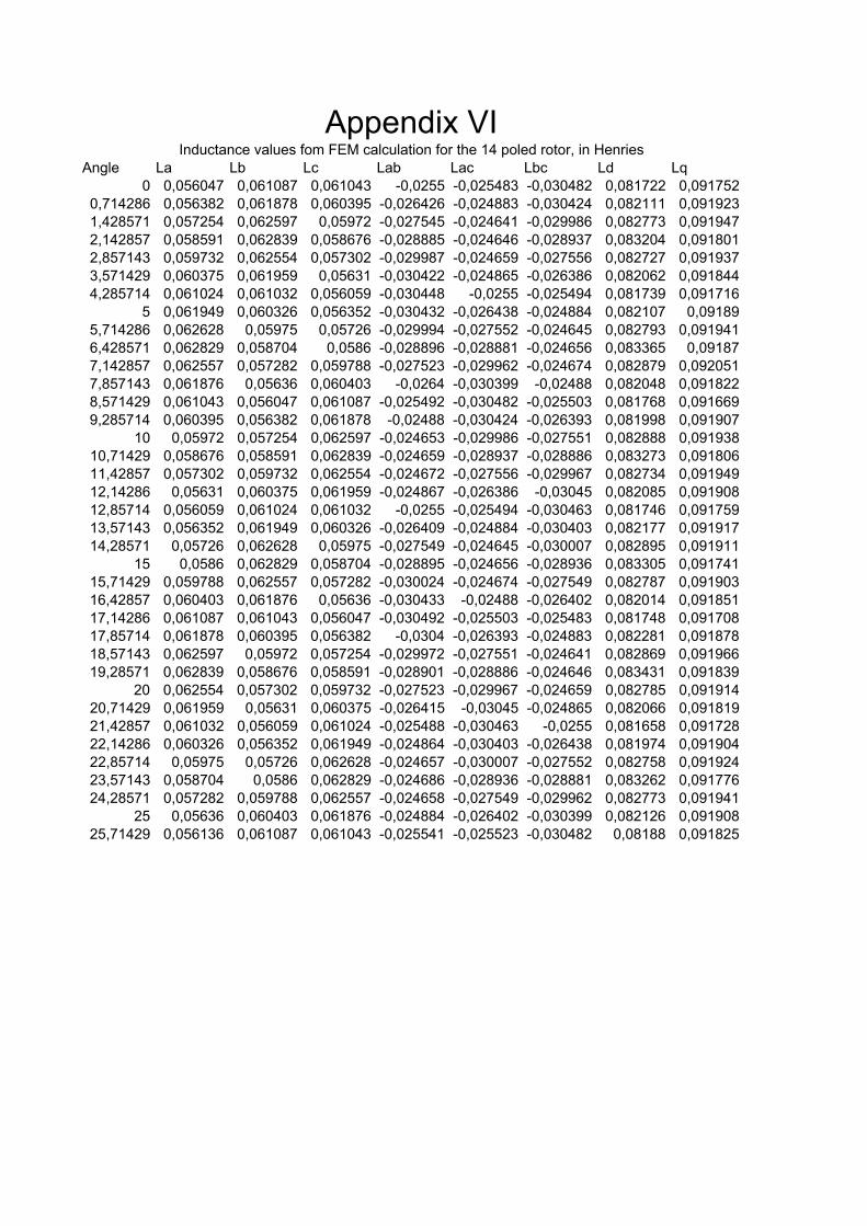
Appendix VIInductance values fom FEM calculation for the 14 poled rotor, in Henries

Angle Ra Rb Rc La Lb Lc Lab Lac Lba Lbc Lca Lcb Ld Lq0,00 6,29324 6,86981 6,93851151 0,055878 0,06123 0,061862 -0,02574 -0,02574 -0,02514 -0,03104 -0,02545 -0,03073 0,081496 0,0924281,07 6,29324 6,93851 6,6774586 0,056049 0,061809 0,059465 -0,02672 -0,02462 -0,02677 -0,0302 -0,02476 -0,03026 0,081466 0,0911922,14 6,47511 6,93851 6,48361846 0,057651 0,06177 0,057733 -0,02872 -0,02445 -0,02832 -0,02894 -0,02423 -0,02877 0,082027 0,0905513,21 6,67746 6,93851 6,29323976 0,059415 0,061738 0,056002 -0,02993 -0,02443 -0,03017 -0,02737 -0,02459 -0,02729 0,081497 0,0912014,29 6,80679 6,93851 6,29323976 0,060553 0,061725 0,055978 -0,0305 -0,02527 -0,03079 -0,02612 -0,02549 -0,02549 0,081606 0,0917825,36 7,07591 6,67746 6,29323976 0,062927 0,059377 0,055978 -0,03078 -0,02673 -0,03083 -0,02411 -0,02668 -0,02428 0,080844 0,0924816,43 7,27941 6,54256 6,41677704 0,06473 0,058178 0,057053 -0,03009 -0,02914 -0,03021 -0,0235 -0,02903 -0,02329 0,081009 0,094057,50 7,00721 6,29324 6,54256045 0,062296 0,055943 0,058165 -0,02766 -0,02952 -0,02757 -0,02397 -0,0299 -0,0241 0,080814 0,0910338,57 6,93851 6,29324 6,81235676 0,061673 0,055937 0,060545 -0,02579 -0,03107 -0,02577 -0,02547 -0,03051 -0,02501 0,08141 0,0918979,64 6,6173 6,81236 6,81235676 0,058805 0,060532 0,060539 -0,02448 -0,02962 -0,02592 -0,02958 -0,02928 -0,02623 0,085026 0,08993
10,71 6,54256 6,41678 6,93851151 0,058116 0,056987 0,061614 -0,02469 -0,02866 -0,02447 -0,0284 -0,02857 -0,02826 0,082133 0,09002611,79 6,40766 6,80112 7,27807657 0,056894 0,060381 0,064616 -0,02468 -0,02804 -0,02483 -0,03073 -0,02809 -0,03129 0,082736 0,0944112,86 6,52632 6,07042 6,18283204 0,058144 0,053894 0,055084 -0,02678 -0,02647 -0,02599 -0,02324 -0,02638 -0,02407 0,084249 0,07814313,93 6,64946 6,85411 6,92943817 0,059222 0,061051 0,061729 -0,02823 -0,02601 -0,03074 -0,02562 -0,02538 -0,03077 0,086486 0,0904315,00 6,78945 7,3452 6,78944952 0,060469 0,065425 0,060475 -0,03013 -0,02538 -0,02992 -0,02959 -0,02538 -0,03013 0,085848 0,09524316,07 7,34666 7,64198 6,77733512 0,065431 0,068069 0,060361 -0,03428 -0,02571 -0,0343 -0,02959 -0,02586 -0,02974 0,087402 0,10166717,14 7,56779 7,49359 6,77733512 0,067401 0,06674 0,060361 -0,0343 -0,02791 -0,0343 -0,02757 -0,0278 -0,02716 0,087979 0,10136518,21 7,58246 7,12556 6,76474564 0,067532 0,063462 0,060249 -0,03325 -0,02919 -0,03329 -0,02597 -0,02967 -0,02538 0,086717 0,09969419,29 8,2087 7,19682 6,98296325 0,073109 0,064097 0,062192 -0,03362 -0,03362 -0,03329 -0,02555 -0,03099 -0,02538 0,088615 0,10513520,36 6,75826 6,76475 6,90004056 0,060191 0,060249 0,061454 -0,02763 -0,0273 -0,03066 -0,02571 -0,0269 -0,02858 0,088472 0,08838221,43 8,04419 8,12977 8,66985886 0,071644 0,072406 0,077208 -0,02796 -0,03822 -0,02897 -0,03827 -0,04231 -0,02909 0,101085 0,11469722,50 7,49511 7,80583 8,05083662 0,066739 0,10174 0,071695 -0,0271 -0,03362 -0,03081 -0,03362 -0,03469 -0,03147 0,117616 0,10626923,57 7,26798 7,19227 7,88311085 0,064717 0,093743 0,070194 -0,0271 -0,03224 -0,0271 -0,03224 -0,03222 -0,03222 0,106334 0,1071424,64 7,19227 7,57397 9,09759572 0,064043 0,098718 0,081009 -0,02641 -0,03224 -0,02766 -0,03502 -0,03402 -0,04082 0,102784 0,12511925,71 7,18993 8,49109 8,49108934 0,064022 0,110671 0,075608 -0,02946 -0,02911 -0,03025 -0,03959 -0,03025 -0,03922 0,100307 0,132524
Locked rotor measurement results for 14 poled rotor, results in ohm and Henries
Appendix VII