fully automated shotcrete robot for rock support · fully automated shotcrete robot for rock...
TRANSCRIPT

Computer-Aided Civil and Infrastructure Engineering 16 (2001) 200–215
INDUSTRIAL APPLICATION
Fully Automated Shotcrete Robot forRock Support
G. Girmscheid & S. Moser*
Institute for Construction Engineering and Management, Swiss Federal Institute of Technology,ETH Zurich-Honggerberg, 8093 Zurich, Switzerland
Abstract: Optimized shotcrete application techniquesare required in particular tunneling projects. Today, anyspraying can be done by hand or by manipulator. Withthe development in the material technologies, the range ofpossible operation was enlarged. With automation of theapplication, an important contribution to improve perfor-mance and quality and to reduce rebound may be achieved.At the Swiss Federal Institute of Technology, Zurich, sys-tematic research is done to develop the fully automatedprocess control, focusing on the wet shotcrete method. Withthe development of the fully automated shotcrete robot, theuser will have a very effective tool at his or her disposal tospray concrete shells (fully automated). With the new robot,the user may choose from three different modes: manual,semiautomated, and fully automated spraying. Especiallythe fully automated mode facilitates higher performancewith less danger to the worker’s health. Quality control isinherent in the application process in regard to layer thick-ness, compaction, and homogeneity.
1 INTRODUCTION
1.1 Shotcrete application on site
Shotcrete is used worldwide as temporary or final lining in
tunnels or in building pits. The application of shotcrete is
strenuous and, because of this, tiring if it is done manually
by a nozzle operator. This holds especially for the use of
wet shotcrete. The capacity that may be handled is less
than 5 to 8 m3/h when spraying manually and normally up
to 20 m3/h by using manipulators (30 m3/h were already
applied).
*To whom correspondence should be addressed. E-mail:
Shotcrete application as the first step of rock support
often has to be done in a zone of danger (rock fall). With
use of the robot, the safety of the worker can be improved.
The handling of the robot is easier and less strenuous than
steering a manipulator. A basic difference between common
manipulators and the new robot is that the user steers the
movements of the nozzle directly. He or she does not have
to take care of the different boom joints. In the manual
and semi-automated mode, the nozzle operator judges the
surface himself or herself to get the required application.
In the fully automated mode, total control is by the robot.
1.2 Delimitation from industrial fabrication robots
The handling of the robot tool, the spraying nozzle, is robo-
tized according to industrial fabrication.21 Different are the
positioning of the carrier vehicle and the recording of the
geometric dimensions. In a spraying cell, the manufactur-
ing area is fenced off clearly. The carrier drives in corridors
and always repeats the same pattern of motion. The dimen-
sion data are transmitted out of CAD drawings.
Blasted tunnel excavation means varying sections that
are not constant not even in a round. The theoretical tun-
nel section is given, and the excavated sections have to be
measured every round. While measuring a round, the self-
positioning of the robot carrier is effected (these data are
stored and available at any time). Any shotcrete application
with a specified layer thickness (effective, theoretical) is a
prototype. The path planning of the vehicle is no topic for
the automation for safety reasons.
2 STATE OF THE ART
Worldwide, much research on shotcrete and application
machines was done in the last 15 years. The new devel-
© 2001 Computer-Aided Civil and Infrastructure Engineering. Published by Blackwell Publishers, 350 Main Street, Malden, MA 02148, USA,
and 108 Cowley Road, Oxford OX4 1JF, UK.
Fully automated shotcrete robot for rock support 201
opments involve the chemical products—water-reducing
admixtures and pumping aids, plasticizers, set accelera-
tors, hydration control, and concrete improver and cur-
ing agents14—and the equipment as well—shotcreting
machines, dosage units, and new nozzle systems—but not
many application techniques. In Germany4,6,8,9,19,26 and
Austria,28 investigation mainly is oriented toward the dry
shotcrete method. In Switzerland, the research is focused
on the wet shotcrete method.3,24,25
2.1 Spraying by hand
Shotcrete is in most cases still applied by nozzle operators
wielding tube and nozzle. The strain on the worker lim-
its the quantity of concrete that can be handled. The tech-
nique of application has to be learned and requires a lot
of experience. The work demands high concentration even
from experienced nozzle operators. To get optimal qual-
ity and a minimum of rebound, the nozzle operator has to
keep the right distance from and angle to the rock surface.
In large tunneling sections, the nozzle operator must apply
the shotcrete from a lifting platform to maintain an optimal
spraying position. If the spraying angle is not perpendic-
ular to the rock surface, the rebound and losses increase
greatly. The right spraying distance depends on the velocity
of the shotcrete at the nozzle. Typical nozzle distances are
between 1 and 2 m. Experience on the sites shows that, due
to human influence, it is not possible to keep all the main
parameters in the best possible combination, especially in
large tunnel sections or high-cut linings.
2.2 Spraying by manipulator
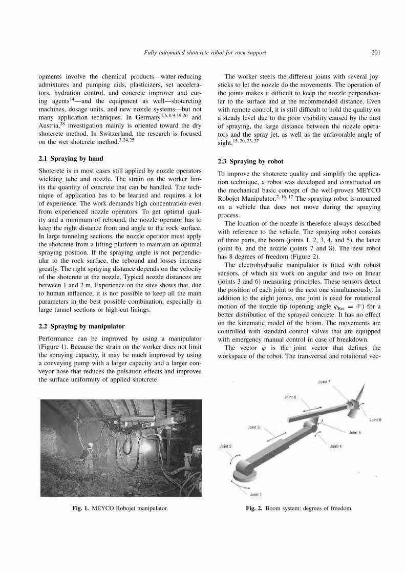
Performance can be improved by using a manipulator
(Figure 1). Because the strain on the worker does not limit
the spraying capacity, it may be much improved by using
a conveying pump with a larger capacity and a larger con-
veyor hose that reduces the pulsation effects and improves
the surface uniformity of applied shotcrete.
Fig. 1. MEYCO Robojet manipulator.
The worker steers the different joints with several joy-
sticks to let the nozzle do the movements. The operation of
the joints makes it difficult to keep the nozzle perpendicu-
lar to the surface and at the recommended distance. Even
with remote control, it is still difficult to hold the quality on
a steady level due to the poor visibility caused by the dust
of spraying, the large distance between the nozzle opera-
tors and the spray jet, as well as the unfavorable angle of
sight.15, 20, 23, 27
2.3 Spraying by robot
To improve the shotcrete quality and simplify the applica-
tion technique, a robot was developed and constructed on
the mechanical basic concept of the well-proven MEYCO
Robojet Manipulator.2, 16, 17 The spraying robot is mounted
on a vehicle that does not move during the spraying
process.
The location of the nozzle is therefore always described
with reference to the vehicle. The spraying robot consists
of three parts, the boom (joints 1, 2, 3, 4, and 5), the lance
(joint 6), and the nozzle (joints 7 and 8). The new robot
has 8 degrees of freedom (Figure 2).
The electrohydraulic manipulator is fitted with robust
sensors, of which six work on angular and two on linear
(joints 3 and 6) measuring principles. These sensors detect
the position of each joint to the next one simultaneously. In
addition to the eight joints, one joint is used for rotational
motion of the nozzle tip (opening angle ϕRot = 4◦) for abetter distribution of the sprayed concrete. It has no effect
on the kinematic model of the boom. The movements are
controlled with standard control valves that are equipped
with emergency manual control in case of breakdown.
The vector ϕ is the joint vector that defines the
workspace of the robot. The transversal and rotational vec-
Fig. 2. Boom system: degrees of freedom.

202 Girmscheid & Moser
1
0ϕ1
ϕ2
2
ϕ3ϕ4
ϕ5
3
4
5 6
7 8ϕ6 ϕ7
ϕ8
NCP9
ϕ9
x
z
y
Fig. 3. Definition of the angles of calculation.
1
5
1
5
ϕ5
ϕ1
Fig. 4. Illustration constraint 1.
tors at the joints involved in the calculation are
ϕT = [ϕ1, ϕ2, ϕ3, ϕ4, ϕ5, ϕ6, ϕ7, ϕ8]T
The task requires the control of 5 degrees of freedom of
the spraying robot, i.e., the position of the nozzle center
point NCP (x, y, z) and two angles for the orientation of
the nozzle (ϕ7, ϕ8). To solve the problem of redundancy,
three constraints are required:
1.
ϕ5 = −ϕ1
3
This condition limits the angle at the nozzle so that
perpendicularity of the nozzle to the rock surface is
possible at any time (Figure 4).
2.
ϕ4 =1+ ϕ2
6
This condition rules out the possibility of a collision
of parts 3 and 6 (Figure 5).
3.
ϕ3 =1.85
3ϕ6
This condition optimizes the workspace of the robot.
These equations guarantee a large workspace and mini-
mize the consumption of oil. The computing is based on the
inverse kinematics principle, which means that for a given
movement of the nozzle, a pattern of motion for each indi-
vidual joint is computed by the mechanical process control.
Due to the complicated kinematic structure of the robot, no
closed-form solution for the inverse kinematic model exists.
ϕ2ϕ4
1 3
ϕ4
1 ϕ2
3
Fig. 5. Illustration constraint 2.
Fig. 6. Remote control (twin bright buttons) with a 6D-joystick.
The joint angles are thus calculated numerically with the
Newton-Raphson method.
The nozzle operator uses a remote control with a six-
dimensional (6D) joystick (Figure 6) to steer directly the
movement of the nozzle, due to the inverse kinematic
mechanical process control, which gives a much higher per-
formance than using common manipulators. The 6D joy-
stick is a large handle with integrated “dead man switch”
and guarantees water and dust resistance. The heart of the
6D joystick is a modified piece of equipment that is used
as a standard in industrial robotics.13, 29, 30
The new robot provides the possibility to choose three
different modes of spraying: fully automated, semiauto-
mated, or manual. The advantages are as follows:
• Very easy, ergonomic control
• Reduced training time

Fully automated shotcrete robot for rock support 203
• Shotcrete quality and performance that are independent
of the nozzle operator’s qualification (semiautomatic and
fully automated mode)
• Tunnel profile measuring and shotcrete application with
one machine
• Possibility to measure sprayed layer thickness
• Saving of time for setup, spraying, and profile control
process
Manual spraying. The worker uses the robot as a manip-
ulator to apply shotcrete manually. Application control is
not supported by application process control, but the move-
ments of the manipulator (boom, lance, nozzle) are con-
trolled by the mechanical control system. This mode is
thought to be appropriate for irregular conditions, where a
description of every movement is too difficult to be imple-
mented into an operational program due to its complexity
or for economic reasons. Such conditions typically could
include
• Extreme irregular local overprofile
• Local covering of drainage half-shells and anchor plates
• Fast repair work with limited extension
• Filling of holes caused by rock fall
After the machine has been positioned, the user oper-
ates the application with the 6D joystick. He or she does
not have to take care of the individual boom joints but
guides only the movement of the nozzle (Figure 7). All
joint movements are process controlled by the mechanical
control system.
The 6D joystick steers
• Angle of the nozzle to the rock surface
• Path line and velocity of the nozzle vn
• Distance dvp from the nozzle tip to the tunnel wall
Semiautomated spraying. The user has the freedom to
choose the path line; all other process functions of the
application are controlled by application process control
and internal mechanical process control. The semiauto-
mated mode is an optional mode that can be used in
areas where neither manual application nor fully auto-
mated mode is economically or technically useful. The
dvp
vnozzle
Fig. 7. Manual spraying mode.
distinguishing difference from manual application mode
is that application process control is generating, in addi-
tion to process control of the mechanical system, a virtual
plane congruent to the scanned wall surface out of laser-
controlled measurements. On this plane, nozzle movement
is computer-controlled with regard to wall distance as well
as to the perpendicularity of the nozzle to the scanned wall
surface. The path of motion is on this virtual plane; it is,
however, manually controlled via the 6D joystick by the
nozzle operator.
The sequence of the application process is as follows:
To give the necessary data to the robot application system,
the tunnel profile has to be measured. Therefore, the user
first marks the required spraying range with a laser device.
The program calculates, out of the automatically measured
data, a virtual plane congruent to the scanned surface in
the distance dvp, and the nozzle tip is automatically guided
perpendicularly to the virtual plane. The spraying distance
dvp (distance from the virtual plane to the rock surface)
has to be specified by the user. In the generated congruent
plane, the driving of the nozzle tip is done by the user
manually with the 6D joystick (Figure 8).
The 6D joystick steers
• The path line of the nozzle on the virtual plane
• The velocity of the nozzle vn
The semiautomated mode avoids increasing rebound,
particularly in ranges that are poorly visible or overhead
and far away from the user, due to optimized nozzle con-
trol with respect to the wall surface. This mode allows full
manual application freedom with regard to layer thickness
or shape of any surface, but the nozzle operator has to judge
the surface by sight to check the layers applied.
Fully automated spraying. In comparison with the other
two modes, the system has to take over the nozzle opera-
tor’s experience and supervision functions with the result-
ing actions. The robot assumes full control of the shotcrete
application process. This mode is in development for the
following conditions:
• Smooth blasted excavations
• Drilled profiles by TBM
dvpvnozzle
Fig. 8. Semiautomated mode.

204 Girmscheid & Moser
dvp
vnozzle
dst
Fig. 9. Fully automated mode.
Measurement is done in the same way as in the semiau-
tomated mode by defining the points where the automated
spraying starts and ends. Depending on the input given by
the user (spraying distance dvp, layer thickness, sprayed
concrete capacity per time unit) the application process
control program calculates the necessary application con-
trol data based on the measured tunnel section data and
the final profile required. The movements are controlled by
the application process control that drives the nozzle auto-
matically in the path line, with the velocity and path line
distance to achieve the required layers or the final profile
by always keeping the nozzle perpendicular to the surface
(Figure 9).
The user only has to specify the requested layer thickness
as well as the capacity of spraying. The path motion of the
nozzle is described in the computer program of application
process control. The distance between the path lines, to
achieve the required layer thickness, is calculated on the
basis of the results of the experiments described later on.
The 6D joystick is locked; but for safety reasons, though,
the user still has to press the dead-man’s switch. This mode
enables the highest average performance over time.
2.4 Control components
Using bus cables, all electrical components of the robot are
connected with the control box. Based on the data from
any single sensor, the computer calculates, depending on
the application task, the appropriate pattern of motion. The
joints are controlled in such a way that none of them are
operated at the limit of their range of movement or exten-
sion and that a minimum of oil volume in the pistons is
used for joint movements to ensure a fast interactive reac-
tion between steering action and process-controlled boom
reaction.
The robot system contains the following main
components:
• Mechanical structure. Boom, lance, nozzle, and sensors
for movement control
• Mechanical process control. Computer (following indus-
trial standards) with flash-EPROM memory and neces-
sary interfaces to connect the system with ethernet to
Internet for remote diagnostics and service, remote con-
trol with 6D joystick, and touch screen with input possi-
bilities and visualization function
• Application process control. Laser measurement system,
application process control program
2.5 Profile measurement in the semiautomated andfully automated modes
Except when using the manual mode, the rock section
under consideration has to be measured as a first step.
The measurement is done by a laser measurement system.
The laser device is located at the head of the lance of
the manipulator (inbetween joints 6 and 7). The range of
measurement along the tunnel axis is limited to 3.00 m
by the mechanical structure of the boom and lance. The
measuring principle is a reflector-less transit-time measure-
ment in the infrared range. The computer program elimi-
nates faulty measurements by an integrated filter function.
The measuring grid is defined by the user. As more mea-
suring points are taken, the real condition is recorded more
exactly. The criteria for choosing the distances of the grid
notches depend on the evenness of the rock surface.
In the fully automated mode, measurement is carried out
twice with the same grid pattern, before and after shotcret-
ing. The computer calculates the layer thickness achieved
at any point on the scanned surface by comparing the zero
measurement of the excavation line with the surface of the
applied shotcrete lining. Joining the profile measurement
with the global tunnel coordinates (allocation of the station-
ing with the corresponding theoretical profile to the profile
measurement of the robot), the final profile control in the
future will be completed as follows:
• Measurement of the excavated tunnel profile by the laser
measurement system
• Feeding of the theoretical profiles into the application
control computer
• Calculation of the necessary shotcrete layer thickness out
of the difference between the excavated and theoretical
profiles of every grid field by the application process con-
trol program
• Calculation of the application velocity between each grid
point out of the interpolated thickness along the grid
path by the application process program (the velocity is
a function of the conveying capacity and the shotcrete
layer thickness).
The layer thickness of each shotcrete application is lim-
ited by the adhesiveness of the concrete and the accelerator
dosage. If the calculated layer thickness exceeds the limit,
the robot decides to apply shotcrete in several layers.

Fully automated shotcrete robot for rock support 205
Fig. 10. Touch screen.
In the other two modes, the thickness must be controlled
manually. The system does not support the computer-
controlled application thickness.
2.6 Application control in the semiautomated andfully automated modes
The computation of any movement is based on inverse
kinematics, which means that for a given path of the
spray jet on the rock surface a regulation for the different
joints is defined. By defining constraints for selected joints,
the redundancies of the kinematic degrees of freedom are
eliminated.11, 12
To arrange the handling as simply as possible, the remote
control alerts the user by twin brightly lighted buttons
(green buttons are used; red ones indicate function in opera-
tion, and unlit buttons are not active) clearly to the selected
operation mode (see Figure 6).
The basic principle of automation is the computation of
a virtual polygonal 3D plane parallel in distance dvp to the
rock surface measured previously. Depending on the mode
chosen for the spraying process, some parameters have to
be given to the system as manual input by touch screen
(Figure 10).
The specified functions are taken over by application pro-
cess control while reducing the nozzle operator’s freedom
of action: full robot control in the fully automated mode
and no application process control in the manual mode.10, 19
The unspecified functions are steered manually by the 6D
joystick. The 6D joystick enables a user-friendly handling.
3 SYSTEM INTELLIGENCE FORAUTOMATED SPRAYING
If knowledge of the independent relations of some spraying
parameters is sufficient for spraying by hand or manipula-
tor, it is not for fully automated spraying by the robot. The
different influences have to be quantified to be put into the
relation. All these dependent and independent factors have
to be programmed in the application process computer pro-
gram (application process control).
Important for the research is the adaptability of any
experiments to site conditions because only this demand
ensures that the results can be implemented usefully in the
robot application system (application program). Because so
many facts cannot be influenced on site, the experimental
data shall not be taken to the last two digits after the dec-
imal point. Much more important is consideration of the
interaction of the material and the application parameters.
3.1 Objectives
Two main fields have to be investigated: the application and
the conveying systems. Application technique, done by a
nozzle operator, includes judging of the profile by sight and
knowledge of the systematic spraying. For fully automated
applications, the operational skills have to be transformed
into “artificial application intelligence.” This means that
all important parameters of the application process have
to be analyzed and optimized in their interrelation, and
then they must be described in an operational application
process control program. This will allow high-performance
shotcrete application in a defined constant layer thickness
or in layers to equalize irregularly blasted profiles (hole fill-
ing) to achieve the theoretical final lining profile with high
quality, an even surface, and minimal rebound. By adher-
ing to these demands, the costs can be reduced effectively.
The basis for reaching this goal is quantification of the dis-
tribution of the spray jet as a single shotcrete strip and the
overlap.
The rebound and the surface evenness of spraying
depend on the acceleration of the concrete by the com-
pressed air at the nozzle, i.e., from the exit velocity of the
concrete, as well as the nozzle distance to the wall. The
relation between the quantity of concrete conveyed and the
pressure of the compressed air must be described in such a
way that in the future the control of concrete capacity and
air pressure will be effected automatically by the system.31
3.2 Research method
For the fully automated application of shotcrete, the texture
uniformity of the surface is very important with regard to
appearance, strength, and water permeability. For the appli-
cation process system of the robot, three types of initial sur-
faces have been defined: smooth surfaces (drilled profiles
by TBM, smooth-blasted regular profiles), rough surfaces
(blasted excavation with overprofile), and surfaces with
steel girder and reinforcement installations. To gain the pro-
cess knowledge for each type of surface, the research at the

206 Girmscheid & Moser
Swiss Federal Institute of Technology Zurich is structured
in five phases:
1. Preliminary tests (only on smooth surfaces)
2. Basic experiments
3. Specific application experiments
4. Creation of calibration tests
5. Validation of the laboratory experiments by site
conditions
With the preliminary tests, the suitability of the devel-
oped robot was checked as well as the recording of
the basic data. Consequently, some adaptation for further
research was done, on the one hand, by modifying the
robot (manipulator, software, laser device) and, on the other
hand, by adaptation of the test program. The basic experi-
ments collected data on the distribution of single-spray-jet
strips. By assessing the results, a hypothesis about the full
range of applications was drawn up. By varying the most
relevant parameters of the basic experiments, the boundary
conditions for useful field employment of the robot (fully
automated mode) were determined in phase 3. With a sim-
ulation, the hypothesis about the full range of applications
was confirmed. The stage of laboratory tests is completed
and supplemented by ongoing experiments on site. In phase
4, specific calibration tests (status of work) will be devel-
oped to transfer the results from the basic and specific
experiments to potential material properties of the specific
mix design as well as the required application technique.
In the last phase, the functionality of the fully automated
mode will be checked on site.
For the complexity of rough surfaces and surfaces with
steel girder and reinforcement installations, the definition
of different zones is necessary. The conditions in each
zone can be treated similarly, e.g., the transition region
between adjoining ranges or the backfilling of girder instal-
lations (pretending the shadowing effect). The systematical
shotcrete application of these zones will be examined by
the research phases 3 to 5.
The test arrangement must ensure the repeatability of any
experiment. This is achieved by
• Controlling the adhesiveness of the fresh concrete
• Using the robot in the semiautomated mode for constant
spraying distance, perpendicular nozzle, constant nozzle
velocity, and constant nozzle rotation
• Measuring from a fixed point for identical measurement
in any experiment1
The first step of the specific application experiments is to
quantify the distribution of the shotcrete by the spray jet in
one layer along the path line. The research has to optimize
a variety of parameter combinations that include distance
of the nozzle to the surface, nozzle moving velocity, noz-
zle motion, quantity of concrete per hour, and quantity
and pressure of air. Different from spraying by hand or by
manipulator, only some system adjustments can be done
while spraying automatically. The reason for this is that
once having left the finished part of the spraying range that
cannot be reached by the spray jet in the same spraying
pass, the evenness of the sprayed surface has to be final.
The quantified distribution curve rectangular to the path
of the spray strip is the basis for the full-range applica-
tion. To spray a homogeneous range, the nozzle path has
to be developed out of the distribution curve of one path.
Depending on the layer thickness required, the spray layers
(distribution curves) have to be overlapped. For this reason,
the distance between nozzle path lines has to be calculated
by an evaluation program.
The operation program with the generated application
intelligence (input is only the layer thickness) calculates the
necessary concrete capacity and compressed air as well as
the pressure and movement parameters of the nozzle path
line, distance, rotation, and velocity.
3.3 Experiments
The following concrete conveying and application system
was used in the experiments:
• Meyco Robojet shotcreting machine, Meyco Suprema
0–20 m3/h, standard spraying nozzle
• Twin air supply, dense conveying, adding accelerator at
the nozzle
Further, the following concrete was used for the
experiments:
• Mix design: CEM I 42.5 450 kg/m3 (Normo 4),22 aggre-
gates 0/8 mm 1736 kg/m3, Delvo stabilizer 1.1 percent,
Rheobuild T3 plasticizer 1.1 percent
• Characteristics: water-cement ratio ≈ 0.47, spread ≈50 cm5, 18
Several series of experiments have been executed with the
following parameters:
• Distance from the nozzle point to the surface dvp: 1.0,
1.5, 2.0 m
• Nozzle moving velocity vn: 10, 15, 20 cm/s
• Nozzle rotation Rn: fix, 1, 2 rps
The parameters were varied in all possible combina-
tions. The concrete conveyance was kept constantly at
10 m3/h. The experiments without nozzle rotation have
been excluded from further tests because of the insuffi-
ciently uniform structure of the sprayed surface.
Basic experiments. The basic experiments were carried out
on a vertical wall with a smooth surface. The shotcrete was
sprayed in single strips on two different and independent
paths that were repeated for statistical reasons. The distri-
bution was measured by laser device on both independent
paths in five parallel profiles. Measurement was done, for

Fully automated shotcrete robot for rock support 207
all experiments, from the same survey point. To eliminate
the pulsation of concrete flow at the beginning and end of
each experiment, the concrete was sprayed into a box until
a homogeneous application was possible. Besides measure-
ment of the distribution perpendicular to the path and the
maximum layer thickness, rebound was registered at the
same time.
The distribution curve of shotcrete dosing at the wall
(design profile) did not vary over the accelerator range of 4
to 8 percent of cement content. For practical experimental
reasons, the dosage was fixed at 4 percent.
Specific application experiments. In phase 3, two test series
with the appropriate parameter sets out of phase 2 that had
the highest evaluation scores with regard to the specified
quality requirements have been selected for further testing
with a conveyed concrete capacity of 15 and 20 m3/h. With
the enlarged capacity, a higher dose of cement was neces-
sary to prevent plugging of the conveyor hose and closing
of the nozzle (CEM I 42.5 500 kg/m3).
The sequence of every experiment was as follows: posi-
tioning of the laser device, quality control of the fresh con-
crete, application with constant conveyance, measurement
of the sprayed strips, weighing of rebound and the totally
sprayed shotcrete, removal of any concrete, and preparation
for the next application.
Besides recording data on shotcrete distribution anal-
ogous to the basic experiments, the theoretical full-
range application was confirmed by laboratory and site
experiments.
3.4 Results of the basic experiments
To give an idea of the results of a single experiment
(concrete conveyance = 10 m3/h, distance of nozzle from
surface dvp = 1.5 m; nozzle velocity vn = 15 cm/s; noz-
zle rotation Rn = 2 rps), the superelevated representation
of four path lines, each measured by five profiles that are
taken along the path lines, is shown in Figure 11 (on the
y axis, every mark means 10 mm; on the x axis, 50 mm).
The maximum thickness of this sprayed strip (single layer)
is between 3.5 and 4.0 cm. The width of the spray strip
(cross-distribution) at the wall is about 1.10 m.
The concrete maximum grain size is 8 mm, which gives
a roughness of the shotcrete at the wall of about 10 mm.
By increasing the dosage of the accelerator, the roughness
may be improved.
The design profile (Figure 12), which is implemented as
a standard strip-distribution profile in the application pro-
cess control program, is determined from the family of dis-
tribution profiles of one path line. It shows that gravity has
a very limited influence even if the spraying is done against
a vertical wall.
The basic requirement for a layer-wise application is the
need for a constant cross-distribution along a path line. For
this reason, the spraying distance dvp for robotic application
has to be kept between 1.50 and 2.00 m. Using a spraying
distance of 2.00 m, nozzle velocities vn between 10 and 20
cm/s and nozzle rotations Rn of 1 or 2 rounds per second
(rps) are possible. Using a spraying distance of 1.50 m, a
nozzle velocity of 10 cm/s and a nozzle rotation of 2 rps
have to be maintained. These parameter combinations result
in a very small standard deviation in design profile.
3.5 Design of the system intelligence
Investigation of the meander-wise path planning of nozzle
motion revealed that the orientation (horizontal, vertical, or
any other orientation in between) of the path lines did not
influence concrete quality with regard to homogeneity and
compressive strength. Rebound of the applied shotcrete did
not vary significantly. These investigations are based on
the dry shotcrete method. The shotcrete is applied with a
modified industrial robot.8
To prevent sagging of the applied shotcrete layers, the
application has to be carried out from the bottom to the
top. Path planning (vertical or horizontal) is technically
determined by the kinematics of the boom and the lance.
Because of the orientation of the lance, application in hor-
izontal meander-wise path lines is predominant.
3.5.1 Hypothesis. Based on the design profile (Figure 12),
which serves as a basis for systematic shotcrete application,
the best application parameter will be filtered with an algo-
rithmic simulation of full-range application, as described
later. Application on a smooth vertical experimental wall is
quite different from application on a rock surface on site
because holes and peaks influence the distribution of the
shotcrete. In a first step, the application is optimized for
smooth surfaces.
The application is executed from the bottom to the top
of the side wall in parallel horizontal path lines. The setup
of every parameter combination remains constant for the
whole spraying process. The design profile is overlapped
in parallel horizontal path lines to build up the final layer
thickness, as shown in Figure 13. The basic design profile
has an extension of 95 cm and a maximum thickness of
0.05 m. With a spraying path line distance of d = 15 cm,
the required total lining thickness of 22 cm is achieved.
The precision of boom, lance, and nozzle movements
limits the path line distance to 0.05 m, with a resulting
maximum theoretical layer thickness of 0.80 m (concrete
capacity 20 m3/h). In practice, the thickness of the sprayed
shotcrete layers will be less than 0.40 m due to insufficient
bond strength. To achieve a uniform distribution along the
path line, the upper limit of the path line distance is equal
to the cone diameter of the nozzle rotation angle. With a
nozzle rotation angle ϕRot of 4 degrees, a path line distance
lower than 21 cm for a spraying distance of 1.50 m and 28
cm for 2.00 m results.

208 Girmscheid & Moser
Distribution profile of single spray-strips
0.050
0.040
0.030
0.020
0.010
0.000
Cross distribution of spray-strips at the wall [mm]
Laye
r thi
ckne
ss m
ax. [
m]
Fig. 11. Concrete cross-distribution curves sprayed in single strips.
Design profile
0.000
0.010
0.020
0.030
0.040
0.050
Cross distribution of spray-strips at the wall [mm]
Laye
r thi
ckne
ss [m
]
Fig. 12. Design profile.
Structure of final layer thickness
Build up of final layer thickness [m]
Laye
r thi
ckne
ss [m
]
0.000
0.050
0.100
0.150
0.200
0.250
0.0 0.3 0.6 0.9 1.2 1.5 1.8 2.1 2.4 2.7 3.0
d
d
dd d d
Fig. 13. Structure of final layer thickness.
3.5.2 Simulation. The experimental data (design pro-
files, rebound, application parameters, water permeability,
compressive strength, air pressure, and concrete character-
istics) are summarized in a database. A programmed algo-
rithm runs through the database, searches for the required
parameter combination, and suggests the optimized adjust-
ment for process control.
The only quality criterion that may be specified by the
user is the evenness of the final shotcrete lining. The even-
ness (Figure 14) specifies the difference between the max-
imal and reduced layer thicknesses applied to the distance
dm of two adjoining maxima:
Evenness = �
dm
� = �m − �r
Three types of evenness have been defined:
• Smooth: � ≤ 10 mm
• Medium: � ≤ 20 mm
• Rough: � ≥ 20 mm

Fully automated shotcrete robot for rock support 209
Δ
d m d m
lm lm lmlr lrLa
yer t
hick
ness
Definition of shotcrete evenness
Fig. 14. Shotcrete application evenness.
Fig. 15. Input mask: evaluation process control.
Changing layer thickness with increasing path distance
0.00
0.05
0.10
0.15
0.20
0.25
0.30
Surface structure: smooth, medium and rough
laye
r th
ickn
ess
[cm
]
Fig. 16. Evenness of different final layer thicknesses.
With algorithmic simulation of the spraying process, the
parameter sets that fit the requirements of a smooth surface
structure (evenness) have been evaluated. The increase in
layer thickness was realized in steps of 0.01 m.
Specifying the evenness of the surface to be sprayed—
smooth, medium, or rough—and classifying the relevance
of rebound to time of spraying, the best process control
parameter set is evaluated automatically for the required
layer thickness (Figure 15). The path line distance is
assigned according to the required layer thickness. These
were simulated for each parameter set out of the whole
database collected from the preliminary and basic experi-
ments.
The simulation of different lining thicknesses for one
chosen parameter set (concrete conveyance = 10 m3/h, dis-
tance nozzle surface dvp = 1.0 m, nozzle velocity vn =10 cm/s, nozzle rotation Rn = 1 rps) is summarized in
Figure 16.
Depending on the path line distance (5–30 cm) and the
parameter set, described above, layer thicknesses of 25 to
5 cm were achieved. The quality of the evenness of the
simulated surface is very different. Application with the
represented parameter set of a layer thickness less than 10
cm, as shown in Figure 16, does not fit the requirement of
a smooth structure of the surface.
A visualization of the fully automated shotcrete appli-
cation (Figure 17) shows two different regions, the tran-

210 Girmscheid & Moser
Fig. 17. Visualization of output parameter set.
sition region where the layer thickness increases and the
constant region. The transition region results from the first
single strip application and the following path line appli-
cation until the layer thickness stays constant as required
(treatment of the transition region will be analyzed in the
next step of research). The stretch of the transition region
depends on the layer thickness and varies between 0.50 and
1.00 m.
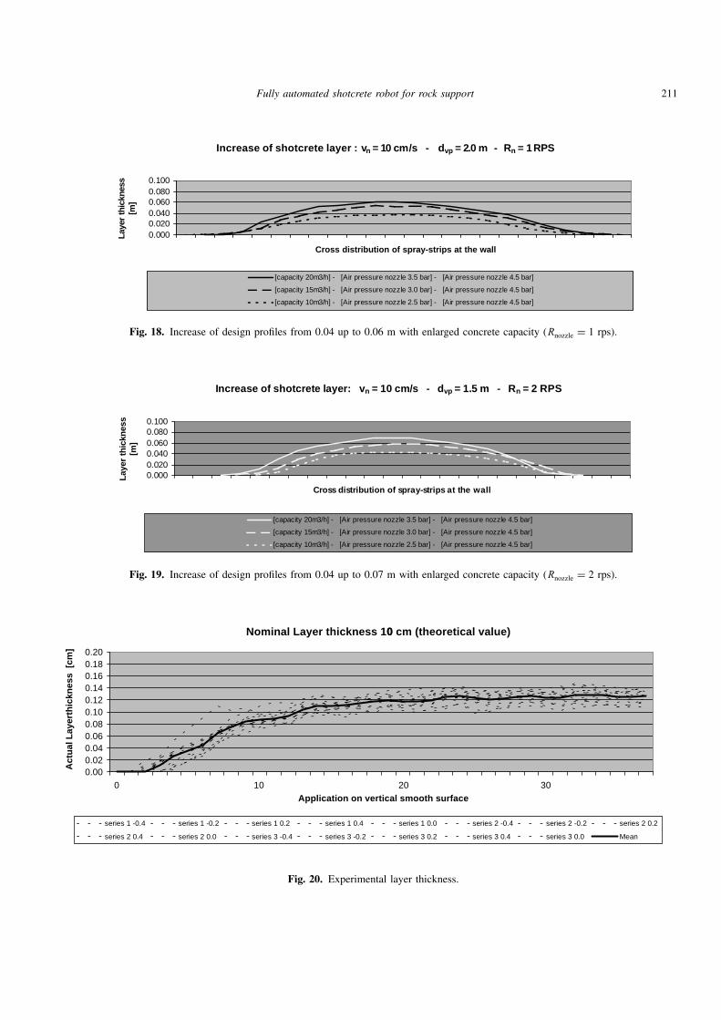
3.6 Results of specific application
The parameter sets that turned out to fulfill the quality
requirements in the simulation were used to enlarge the
spraying capacity to 15 and 20 m3/h. The maximal design
profile thickness that may be achieved varies between 0.02
and 0.07 m depending on the parameter set chosen and
the concrete conveying capacity of 10, 15, or 20 m3/h
(Figures 18 and 19).
Figure 20 shows a verification test. The following find-
ings have been made in comparison with the theoretical
buildup of the layer thickness (constant region):
1. The surface appears scaly (the scaly appearance
depends on the accelerator dosage; with increasing
dosage up to 8 percent of cement content, homogene-
ity improves.
2. The layer thickness is enlarged.
3. The standard deviation of different sections is maxi-
mal and equal to 1.2 times grain size max.
The experiments showed that the layer thickness of
the design profile increases with application on setting
shotcrete instead on rock. Due to the overlapping of the
different spray strips to achieve the theoretical layer thick-
ness, the rebound is decreasing, and therefore, the design
profile is enlarged. The value of the increase is proportional
to the gradient of the design profile (application on rock).
A quantified increase of 0.001 to 0.003 m is reverse pro-
portional to the thickness of the design profile.
The practical application thickness is increased in rela-
tion to the theoretical layer thickness. This phenomenon
was studied in several experiments and quantified by the
following correction functions:
y = −0.1357x + 2.0291 (R2 = 0.93)
for layer thickness up to 0.05 m and
y = −0.0189x + 1.4242 (R2 = 0.98)
for layer thickness above 0.05 m.
The recommended parameter sets of the simulation have
been verified for layer thicknesses of 0.05 to 0.11 m and
0.15 m and 0.20 m at laboratory conditions. The standard
deviation of the measured shotcrete linings generally was
less than ±1 cm.
3.7 Summary of laboratory experiments
All applications of the laboratory experiments were exe-
cuted with the semiautomated or the fully automated mode
of the Meyco Robojet. The spraying distance dvp, the noz-
zle velocity vn, and the perpendicularity of the nozzle to
the rock surface were controlled by the application control
system and at all times maintained precisely. Besides regis-
tration of surface evenness and rebound, the strength after
7 and 28 days, as well as the water permeability, has been
examined. The water permeability is an effective criterion
for a check of the bond between the sprayed layers and
separation of the concrete texture. The water permeabil-
ity correlates with the compressive strength. The increase
Fully automated shotcrete robot for rock support 211
Increase of shotcrete layer : v n = 10 cm/s - dvp = 2.0 m - Rn = 1 RPS
0.0000.0200.0400.0600.0800.100
Cross distribution of spray-strips at the wall
Laye
r thi
ckne
ss[m
]
[capacity 20m3/h] - [Air pressure nozzle 3.5 bar] - [Air pressure nozzle 4.5 bar]
[capacity 15m3/h] - [Air pressure nozzle 3.0 bar] - [Air pressure nozzle 4.5 bar]
[capacity 10m3/h] - [Air pressure nozzle 2.5 bar] - [Air pressure nozzle 4.5 bar]
Fig. 18. Increase of design profiles from 0.04 up to 0.06 m with enlarged concrete capacity (Rnozzle = 1 rps).
Increase of shotcrete layer: vn = 10 cm/s - dvp = 1.5 m - Rn = 2 RPS
0.0000.0200.0400.0600.0800.100
Cross distribution of spray-strips at the wall
Laye
r thi
ckne
ss[m
]
[capacity 20m3/h] - [Air pressure nozzle 3.5 bar] - [Air pressure nozzle 4.5 bar]
[capacity 15m3/h] - [Air pressure nozzle 3.0 bar] - [Air pressure nozzle 4.5 bar]
[capacity 10m3/h] - [Air pressure nozzle 2.5 bar] - [Air pressure nozzle 4.5 bar]
Fig. 19. Increase of design profiles from 0.04 up to 0.07 m with enlarged concrete capacity (Rnozzle = 2 rps).
Nominal Layer thickness 10 cm (theoretical value)0
0.000.020.040.060.080.100.120.140.160.180.20
0 10 20 30Application on vertical smooth surface
Act
ual L
ayer
thic
knes
s [c
m]
series 1 -0.4 series 1 -0.2 series 1 0.2 series 1 0.4 series 1 0.0 series 2 -0.4 series 2 -0.2 series 2 0.2
series 2 0.4 series 2 0.0 series 3 -0.4 series 3 -0.2 series 3 0.2 series 3 0.4 series 3 0.0 Mean
Fig. 20. Experimental layer thickness.
212 Girmscheid & Moser
in compressive strength between the seventh and twenty-
eighth days is, for the experimental parameter sets, very
similar.
The laboratory experiments resulted in the following
findings: Nozzle rotations of 1 or 2 rounds per second (rps)
reduce the pulsation effect, which gives a better evenness.
With nozzle velocities of less than or equal to 20 cm/s, the
uniformity improves. With increasing distance (1.5–2.0 m)
from the nozzle tip to the rock surface, the spraying figure
gets more homogeneous. With distances between 1.5 and
2.0 m from the nozzle point to the rock surface, the rebound
changes for the given concrete conveyance as follows: It
increases greatly for 10 m3/h, increases little for 15 m3/h,
and decreases for 20 m3/h. The compressive strength for
all parameter combinations (smooth surface) is higher for
a spraying distance of 2.0 m than for a spraying distance
of 1.5 m. These trends have become more or less apparent,
depending on the air pressure at the nozzle (2.25, 2.75, or
3.5 bar). The air pressure at the compressor was constantly
4.5 bar. This indicates that not only the air consumption but
also and even more the effective air pressure at the nozzle
are key factors for the rebound.
3.8 Application on site
Considering the correction functions (Figures 21 and 22),
the transition from laboratory experiment to application on
site was achieved. Shotcrete application was carried out
with an accelerator dosage of 4, 6, and 8 percent. Shotcrete
was applied on presprayed rock and on blasted rock both
washed previously with water.
For any application, the excavation line is evened out
by the shotcreting, holes are partially filled, and peaks are
covered less.27 The overlaying of several spraying paths
(design profile) has a balancing effect that optimizes the
homogeneity of the final surface. With the following lower
limits of accelerator dosages, sagging and falling in the
crown were avoided: 4 percent for a layer thickness of 0.05
m on presprayed rock, 6 percent for a layer thickness of
0.12 m on presprayed rock and 0.08 m on blasted rock,
and 8 percent for a layer thickness of 0.15 m on presprayed
rock and 0.12 m on blasted rock.
The application was executed from the bottom of the
side wall to the center of the crown (smooth-blasted exca-
vation). In each of these sections, several profiles have
been measured. In Figure 23, the developed length, from
the side wall to the crown, is shown (three profiles mea-
sured). The required layer thickness (theoretical profile)
is 0.10 m. According to reference 23, the tolerances of
excavation support for shotcrete shells less than or equal
to 15 cm is −0.01 m. With the simulated and corrected
parameter combination, the fully automated shotcrete appli-
cation achieves very easily the required shotcrete lining
of 0.10 m.
The effective lining (mean) does not fall below the tol-
erance of 0.09 m. A few points, measured on peaks, do
not achieve the limit. Measured points at holes, caused by
overbreak, give a lining thickness of 0.11 to 0.12 m. While
spraying shotcrete meander-wise in path lines, peaks are
covered less and holes are filled. To guarantee at any point
the theoretical layer thickness, too much shotcrete would
be applied. The profile shown (Figure 24) represents the
situation locally in detail.
The basic requirement of fully automated application
(quality control is inherent in the application process) is to
rule out that the sprayed layer thickness falls below toler-
ance. The fully automated shotcrete application guarantees
the best, precise layer thickness possible, fulfilling the stan-
dard of underground work.23
3.9 Recommendations for shotcrete application
The smaller the layer thickness of the design profile and
the smaller the path line distance, the better is the evenness
of the final layer thickness. Conveying capacities of 10 to
20 m3/h are mainly suitable for preapplication (filling of
cracks and holes) or for layer thicknesses larger than 0.20
m. To prevent sagging of the fresh concrete and a scaly
appearance, the shotcrete layers should be 5 to 15 cm thick.
The evenness gets better with a higher dosage of accelera-
tor; dosages lower than 5 to 6 percent should be avoided.
4 CONCLUSION
Different boundary conditions on site require different
application modes. The manual mode of the robot is mainly
for shotcrete application on extraordinary surface irregu-
larities, e.g., local overbreaks. The semiautomated mode
improves the quality of the shotcrete by taking over some
functions from the nozzle operator. The fully automated
mode guarantees high performance, quality, and a constant
layer thickness at the same time. With regard to the situ-
ation on site, the user may select the most efficient mode
for the application process.
A single formula that describes all parameters in gen-
eral does not exist. It is not difficult to make suggestions
regarding the right application technique for any single
parameter (nozzle distance, nozzle velocity, concrete capac-
ity, air pressure, rebound, etc.). Some important system
parameters have to be interrelated because of their inter-
dependence with reference to application intelligence to
control the entire automated application process. The user
may select some important parameters to set priorities
between rebound, evenness, and performance of spraying;
i.e., doing the application without the best possible even-
ness, the concrete conveying capacity may be enlarged,
which reduces the time of spraying, or if high performance
does not matter, a parameter set is chosen that minimizes

Fully automated shotcrete robot for rock support 213
Linear correction function: layer thickness up to 0.05 m
y = -0.1357x + 2.0291R2 = 0.93
0
5
10
15
3.5 4 5
theoretical layer thickness [cm]s
nom
inal
laye
rth
ickn
ess
[cm
]
theoretical layer thickness nominal layer thickness proportionality function linear trend
Fig. 21. Correction function theoretical-nominal layer thickness (layer thickness up to 0.05 m).
Linear correction function: layer thickness >0.05 m
y = -0.0189x + 1.4242R2 = 0.98
0
5
10
15
20
25
6 7 8 9 10 11 12 13 14 15 16 17 18 19 20
theoretical layer thickness [cm]
nom
inal
laye
rth
ickn
ess
[cm
]i
lr
theoretical layer thickness nominal layer thickness proportionality function exponential trend
Fig. 22. Correction function theoretical-nominal layer thickness (layer thickness > 0.05 m).
Fully automated spraying: standard mix design, 8% alkalifree accelerator
0.00
0.02
0.04
0.06
0.08
0.10
0.12
0.14
0.16
0 1 2 3 4
Developed section length: side wall (left)- crown (right) [m]
Laye
r thi
ckne
ss [m
]
Measured profile Measured profile Measured profile
Theoretical profile Tolerance (Standard: CH-SIA 198) Effective profile (mean)
Fig. 23. Layer control of fully automated shotcrete application.

214 Girmscheid & Moser
Deviation actual - nominal lining
-2
-1
0
1
2
3
4
5
0 1 2 3 4 5 6 7
width [m]
heig
ht
[m
]
2
2.5
5.5 6
Rock section
Sprayed layer thickness
Theoretical shotcrete thickness
Tolerance actual - nominal lining
Fig. 24. Shotcrete application in a blasted tunnel section.
rebound. With calibration tests (in development), the differ-
ent concrete mixes as well as the conditions on site can be
adopted to transfer the basic process data (gained out of the
experiments) into the adjusted requirements for any site.
The fully automated shotcrete process has high potential
for application in areas with quite uniform site conditions
to step up the performance and overall quality of shotcrete.
In combination with other high-performance equipment in
the construction process chain for drill and blast as well
as TBM advancing, the shotcrete robot is one element to
improve the profitability of tunnel construction.
REFERENCES
1. Amberg Messtechnik AG, Profiler 4000, Regensdorf,
Switzerland, 1997.
2. Bock, T., Moglichkeiten und Beispiele fur Robotereinsatze im
Bauwesen, VDI-Berichte Nr. 800, 1990, pp. 137–58.
3. Cornejo-Malm, G., Schwinden von Spritzbeton, Eidge-
nossische Technische Hochschule Zurich, Institut fur Baupla-
nung und Baubetrieb, Zurich, Switzerland, 1995.
4. Diecken, U. v., Moglichkeit zur Reduzierung des Ruckpralls
von Spritzbeton aus verfahrenstechnischer und betontech-
nologischer Sicht, technical report 89-2, Ruhr Universitat
Bochum, Institut fur konstruktiven Ingenieurbau, Bochum,
Germany, 1989.
5. Garshold, K. & Melbye, T., Practical experience with alkali-
free, non-caustic liquid accelerators for sprayed concrete,
in Second International Symposium on Sprayed Concrete,September 23–26, Gol, Norway, 1996.
6. Gipperich, Ch., Verfahrenstechnische Ursachen richtung-
sorientierter Inhomogenitaten bei der Herstellung von
Spritzbeton, technical report 94-5, Ruhr Universitat Bochum,
Institut fur konstruktiven Ingenieurbau, Bochum, Germany,
1994.
7. Girmscheid, G., Rationalisierung und Kosteneffizienz beim
Sprengvortrieb durch Teil-Roboterisierung und Innovatio-
nen, Soderdruck anlasslich des 40 jahrigen Firmenjubilaums,
MEYCO Equipment, MBT (Schweiz) AG, Winterthur,
Switzerland, 1997.
8. Guthoff, K., Einflusse automatischer Dusenfuhrung auf die
Herstellung von Spritzbeton, technical report 91-7, Ruhr
Universitat Bochum, Institut fur konstruktiven Ingenieurbau,
Bochum, Germany, 1991.
9. Handke, D., Kriterien zur Beurteilung und Verminderung
der Staubentwicklung bei Spritzbetonarbeiten im Tunnelbau,
technical report 87-3, Ruhr Universitat Bochum, Institut fur
konstruktiven Ingenieurbau, Bochum, Germany, 1987.
10. Hess, A. & Trigo, M., Bahnplanung fur den MEYCO-Robo-
jet. Semesterarbeit, Eidgenossische Technische Hochschule
Zurich, Institut fur Robotik, Zurich, Switzerland, 1997.
11. Honegger, M., Steuerung fur den Betonspritzroboter Robo-
jet SC-30, Interner Bericht, Eidgenossische Technische
Hochschule Zurich, Institut fur Robotik, Zurich, Switzerland,
1996.
12. Honegger, M. & Codourey, A., Redundancy resolution of
a cartesian space operated, heavy industrial manipulator,
in Proceedings of ICRA’98, International Conference onRobotics and Automation, Leuven, Belgium, May 16–21,
1998.
13. Honegger, M., Schweitzer, G., Tschumi, O. & Amberg,
F., Vision supported operation of a concrete spraying
robot for tunneling work, in Fachvortrag an “Mechatron-ics and Machine Vision in Practice,” Toowoomba, Australia,
September 23–25, 1997.
14. Jobsite Manager, MBT Underground Construction, Zurich,
Switzerland, 1996.

Fully automated shotcrete robot for rock support 215
15. Laich SA, 6. Spritzbetonkolloqium, TFB Wildegg, Wildegg,
Switzerland, September 26, 1997.
16. Maidl, B., Spritzbetonroboter im Tunnelbau, VDI-Berichte
Nr. 800, 1990, pp. 207–36.
17. Meierhofer, L., Marktstudie “Programmgesteuerter Spritz-
roboter (Projekt SC-30),” Internes Papier Meynadier AG,
Zurich, Switzerland, 1993.
18. Melbye, T., Sprayed concrete for rock support, MBT Interna-
tional Underground Construction Group, Zurich, Switzerland,
1994.
19. Ngamani, G. S., Die Automatisierung der Dusenfuhrung
zur Auftragung von Spritzbeton, technical report 96-8, Ruhr
Universitat Bochum, Institut fur konstruktiven Ingenieurbau,
Bochum, Germany, 1996.
20. Osterreichischer Betonverein, Richtlinie Spritzbeton—Grun-
druck, Wien, Austria, 1997.
21. Penin, L. F., Balaguer, C., Pastor, J. M., Rodriguez, F. J.,
Barrientos, A. & Aracil, R., Robotized spraying of prefabri-
cated panels, IEEE Robotics & Automation Magazine, 5 (3)
(1998), 18–29.
22. Schweizerischer Ingenieur- und Architekten-Verein, Beton-
bauten SIA 162, Zurich, Switzerland, 1993.
23. Schweizerischer Ingenieur- und Architekten-Verein, Unter-
tagebau SIA 198, Zurich, Switzerland, 1993.
24. Seith, O., Spritzbeton bei hohen Temperaturen, Eidge-
nossische Technische Hochschule Zurich, Institut fur Baupla-
nung und Baubetrieb, Zurich, Switzerland, 1995.
25. SUVA, Forschungsprojekt ALPTRANSIT “Das Nass-Spritz-
verfahren als Alternative zum Trocken-Spritzen mit che-
mischen Zusatzen,” Luzern, Switzerland, 1992.
26. TBG, Ruhr-Universitat Bochum “Arbeits- und Gesund-
heitsschutz durch die Reduzierung der Staubentwick-
lung im Dusenbereich,” Schlussbericht, Bochum, Germany,
1995.
27. Teichert, P., Spritzbeton, Laich SA, Avegno, Schweiz, 1991.
28. Testor, M., Vergleich umweltneutraler Spritzbetontech-
nologien im Baustellenversuch, Schlussbericht, Leopold-
Franzens-Universitat Innsbruck, Institut fur Baustofflehre und
Materialprufung, Innsbruck, Austria, 1996.
29. Tschumi, O., MEYCO Robojet Logica, presentation at CIM
Conference 1998, Montreal, Canada, Internes Papier MEYCO
Equipment MBT (Schweiz) AG, Winterthur, Switzerland,
1998.
30. Tschumi, O., Fully automated shotcrete robot—Machine
design, in Third International Symposium on Sprayed Con-crete, Gol, Norway, September 26–29, 1999.
31. Wijnhoff, M., Moser, S. & Girmscheid, G., Forschungs-
beitrag Spritzbeton, Diplomarbeit, Eidgenossische Technische
Hochschule Zurich, Institut fur Bauplanung und Baubetrieb,
Zurich, Switzerland, 1999.