fulton pulse vlp vertical low pressure steam boilers · fulton pulse vlp vertical low pressure...
TRANSCRIPT
Fulton Heating Solutions, Inc. PVLP-IOM-2011-0617
Page 1
Fulton Pulse VLP Vertical Low Pressure
Steam Boilers
Installation, Operation and Maintenance Manual
Fulton Heating Solutions, Inc. 972 Centerville Road Pulaski, NY 13142 Telephone: (315) 298-5121 Facsimile: (315) 298-6390 www.fulton.com
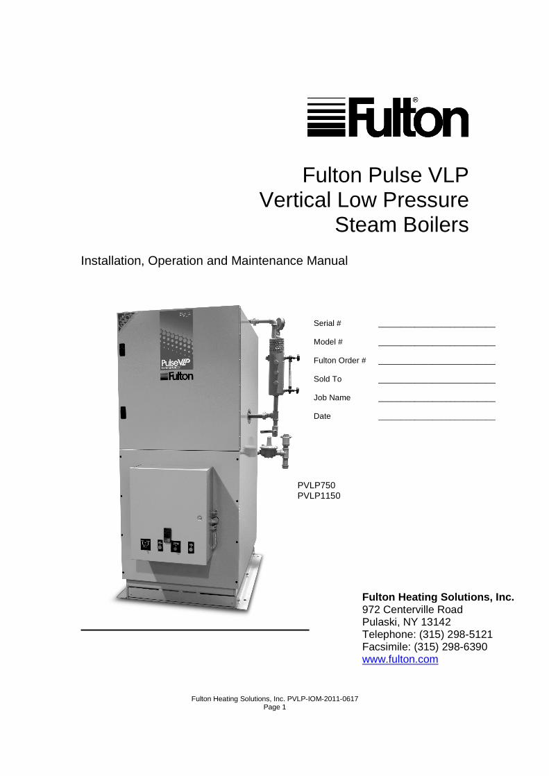
PVLP750 PVLP1150
Serial # __________________________ Model # __________________________ Fulton Order # __________________________ Sold To __________________________ Job Name __________________________ Date __________________________

Fulton Heating Solutions, Inc. PVLP-IOM-2011-0617
Page 2
Fulton Heating Solutions, Inc. PVLP-IOM-2011-0617
Page 3
Fulton Pulse VLP Vertical Low Pressure Steam Boilers
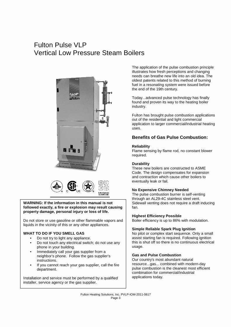
The application of the pulse combustion principle illustrates how fresh perceptions and changing needs can breathe new life into an old idea. The oldest patents related to this method of burning fuel in a resonating system were issued before the end of the 19th century. Today...advanced pulse technology has finally found and proven its way to the heating boiler industry. Fulton has brought pulse combustion applications out of the residential and light commercial application to larger commercial/industrial heating uses. Benefits of Gas Pulse Combustion: Reliability Flame sensing by flame rod, no constant blower required. Durability These new boilers are constructed to ASME Code. The design compensates for expansion and contraction which cause other boilers to eventually leak or fail. No Expensive Chimney Needed The pulse combustion burner is self-venting through an AL29-4C stainless steel vent. Sidewall venting does not require a draft inducing fan. Highest Efficiency Possible Boiler efficiency is up to 86% with modulation. Simple Reliable Spark Plug Ignition No pilot or complex start sequence. Only a small assist starting fan is required. Following ignition this is shut off so there is no continuous electrical usage. Gas and Pulse Combustion Our country's most abundant natural resource...gas... combined with modern-day pulse combustion is the cleanest most efficient combination for commercial/industrial applications today.
WARNING: If the information in this manual is not followed exactly, a fire or explosion may result ca using property damage, personal injury or loss of life. Do not store or use gasoline or other flammable vapors and liquids in the vicinity of this or any other appliances. WHAT TO DO IF YOU SMELL GAS
• Do not try to light any appliance. • Do not touch any electrical switch; do not use any
phone in your building. • Immediately call your gas supplier from a
neighbor’s phone. Follow the gas supplier’s instructions.
• If you cannot reach your gas supplier, call the fire department.
Installation and service must be performed by a qualified installer, service agency or the gas supplier.

Fulton Heating Solutions, Inc. PVLP-IOM-2011-0617
Page 4
Fulton Heating Solutions, Inc. PVLP-IOM-2011-0617
Page 5
Table of Contents
Section 1 – Safety Warnings &
Precautions
Section 2 – Installation
1. General Specifications
2. Introduction
3. Standard Trim
4. Recommended Water Conditions
5. Water Supply
6. Glossary of Water Supply Terms
7. Locating the Boiler
8. Installing Spring Isolation Mounts
9. Installing Seismic Spring Isolation
Mounts
10. Installing Boiler Trim
11. Installing Feed Water Piping
12. Installing Condensate Drain Piping
13. Installing Steam Pressure Gauge
Assembly
14. Installing Water Level Control
Assembly
15. Installing Gas Piping
16. Installing Field Wiring
17. Air Intake Supply Piping Installation
Preparation
18. Intake Muffler Installation
19. Exhaust Vent Piping Installation
Preparation
20. Exhaust Muffler Installation
21. Air Intake Supply & Exhaust Vent
Installation
22. Vertical Vent Flashing & Installation
23. Vertical Vent Termination
24. Horizontal Installation Wall
Penetrations
25. Wall Thimble Installation
26. Horizontal Vent Termination
27. Installation Checkpoints
28. Testing Ignition Safety Shutoff
29. Measure Gas Flow Rate
30. To Correct Input-Adjust Gas
Pressure Regulator
31. To Check for High Gas Pressure
32. For High Gas Pressure Installations
33. Cleaning the Pressure Vessel
34. Before Leaving the Installation
Section 3 – Operation
1. Instructions
2. Start-Up Preparation
3. Starting the Fulton Pulse
Combustion Boiler
4. If The Boiler Does Not Start
5. Sequence of Operation
6. Sequence of Operation for
Modulated Pulse Steam Boilers
7. Programming Instructions for
Yokogawa UT320 Standard
Program
8. Worksheets
9. Advanced Programming Features
10. Standard Program for UT350
11. Linkage Adjustment for Pulse
Modulated Boilers
12. Prior to Start-Up
13. Setting High Fire
14. Linkage Relationships
Fulton Heating Solutions, Inc. PVLP-IOM-2011-0617
Page 6
15. Gas Butterfly Valve
16. Exhaust Butterfly Valve
17. Low Fire Settings
18. Procedure to Zero and Span the
Modulation Motor
Section 4 – Maintenance
1. Before Each Heating Season
2. Recommended Weekly
Maintenance
3. Procedure for Cleaning Water
Probes
4. Recommended Monthly
Maintenance
5. Recommended Quarterly
Maintenance
6. Recommended Six Month
Maintenance
7. Recommended Annual Maintenance
8. Troubleshooting
Section 5 – Parts & Warranty

Fulton Heating Solutions, Inc. PVLP-IOM-2011-0617
Page 7
Section 1

Fulton Heating Solutions, Inc. PVLP-IOM-2011-0617
Page 8
Fulton Heating Solutions, Inc. PVLP-IOM-2011-0617
Page 9
Section 1 – Safety Warnings & Precautions
For Your Safety
The following WARNINGS, CAUTIONS and NOTES appear in various chapters of this manual.
They are repeated on these safety summary pages as an example and for emphasis.
• WARNINGS must be observed to prevent serious injury or death to personnel.
• CAUTIONS must be observed to prevent damage or destruction of equipment or loss of
operating effectiveness.
• NOTES must be observed for essential and effective operating procedures, conditions, and
as a statement to be highlighted.
It is the responsibility and duty of all personnel involved in the operating and maintenance of this
equipment to fully understand the WARNINGS, CAUTIONS and NOTES by which hazards are to
be eliminated or reduced. Personnel must become familiar with all aspects of safety and equipment
prior to operation or maintenance of the equipment.
Note
The boiler must not be installed on carpeting. Sect ion 2.
Warning
The boiler shall be installed such that the gas ign ition system components are protected
from water (dripping, spraying, rain, etc.) during boiler operation and service. Section 2.
Note
All pulse combustion boilers must be installed with vibration isolators. No pulse combustion
boiler shall be lagged directly to the concrete flo or due to the transfer of vibration. In the box
of trim shipped with each pulse boiler, Fulton supp lies 4 elastomer coated fiberglass cubes
used for vibration isolation. For all non-critical installations these 3" x 3" x 2" cubes must be
under each foot of the boiler. Flex connectors must be installed on the water inlet and outlet
lines. For installations near “sensitive” areas suc h as offices, classrooms, or hospital
rooms, spring mounts-which fit under the corner of each boiler-must be used instead of the
cubes, and flex connectors must be installed on the water inlet and steam outlet lines. Flex
connectors may be installed on the gas inlet if nec essary. Spring loaded pipe hangers may
be used on the air inlet, water inlet and outlet, a nd the flue gas outlet pipes, Contact your
Fulton Representative for vibration isolation packa ges designed specifically for your
Fulton Heating Solutions, Inc. PVLP-IOM-2011-0617
Page 10
application. Section 2.
Warning
The discharge from safety relief valve shall be so arranged that there will be no danger of
scalding of personnel. Section 2.
Note
No shutoff of any kind shall be placed between the safety relief valve and the boiler or on the
discharge pipe between such valve and the atmospher e. Doing so can cause an accidental
explosion from over-pressure. Section 2.
Note
Intake PVC piping must be assembled using cement. T his will ensure that the intake is
airtight and will not allow contaminates from the b oiler room into the boiler. Section 2.
Note
See table on Page 15 for required pipe size, based on overall length of pipe from meter plus
equivalent length of all fittings. Approximate sizi ng may be based on 1 cubic foot of natural
gas per 1,000 BTU/Hr. input. Section 2.
Note
Piping schematic consistent with the ANSI/ASME Boil er & Pressure Vessel Code Section IV.
Section 2.
Caution
Some soaps used for leak testing are corrosive to c ertain types of metals. Rinse all piping
thoroughly with clean water after leak check has be en completed. Section 2.
Note
Do not use matches, candles, flame or other sources of ignition to check for gas leaks.
Section 2.
Note
The vent line connection on the gas pressure regula tor and the low and high gas pressure
switches must be piped to outdoor air by installer in accordance with the National Fuel Gas
Code. Section 2.
Fulton Heating Solutions, Inc. PVLP-IOM-2011-0617
Page 11
Warning
Do not attempt to start boiler to test wiring befor e filling and purging the boiler. A dry-fire
will seriously damage the boiler and may result in property damage or personnel injury and
is not covered by warranty. Section 2.
Warning
Solvent cements for plastic pipe are flammable liqu ids and should be kept away from all
sources of ignition. Proper ventilation should be m aintained to reduce the hazard and to
minimize breathing of solvent vapors. Avoid contact of cement with skin and eyes. Section
2.
Note
It is recommended that an authorized Fulton Pulse s tart up agent or your gas utility make
any required gas input adjustments. Section 2.
Warning
If you do not follow these instructions exactly a f ire or explosion may result causing
property damage, personnel injury, or loss of life. Section 3.
Note
Do not use this boiler if any part has been under w ater. Immediately call a qualified service
technician to inspect the boiler and to replace any part of the control system and/or gas
control(s), which have been under water. Section 3.
Caution
Should overheating occur or the gas supply fails to shut off, shut off the gas supply at a
location external to the boiler. Section 3.
Caution
The flame safety pressure switch in this unit has b een pre-set at the factory. Do not attempt
to change any settings. Section 3.
Fulton Heating Solutions, Inc. PVLP-IOM-2011-0617
Page 12
Caution
If the boiler is being operated automatically on a time clock, the blow down operation may
be done at the end of the day. Section 4.
Note
If for any reason, the air intake or exhaust vent p iping is disassembled, re-assemble the
piping in accordance with the installation procedur e outlined in the installation section of
this manual. Section 4.
Note
Your Fulton Pulse Combustion Boiler has been design ed for years of trouble-free
performance. To ensure the continued safety and eff iciency of the boiler, the schedule of
maintenance outlined in this section should be adhe red to. The boiler should be inspected
annually. All service should be performed by a cert ified contractor. Section 4.
Warning
Keep boiler area clear and free from combustible ma terials, gasoline and other flammable
vapors and liquids. Section 4.
Fulton Heating Solutions, Inc. PVLP-IOM-2011-0617
Page 13
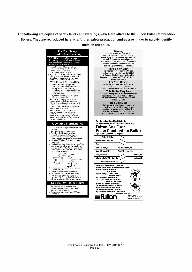
The following a re copies of safety labels and warnings, which are affixed to the Fulton Pulse Combustion
Boilers. They are reproduced here as a further safe ty precaution and as a reminder to quickly identify
them on the boiler.

Fulton Heating Solutions, Inc. PVLP-IOM-2011-0617
Page 14

Fulton Heating Solutions, Inc. PVLP-IOM-2011-0617
Page 15
Section 2

Fulton Heating Solutions, Inc. PVLP-IOM-2011-0617
Page 16
Fulton Heating Solutions, Inc. PVLP-IOM-2011-0617
Page 17
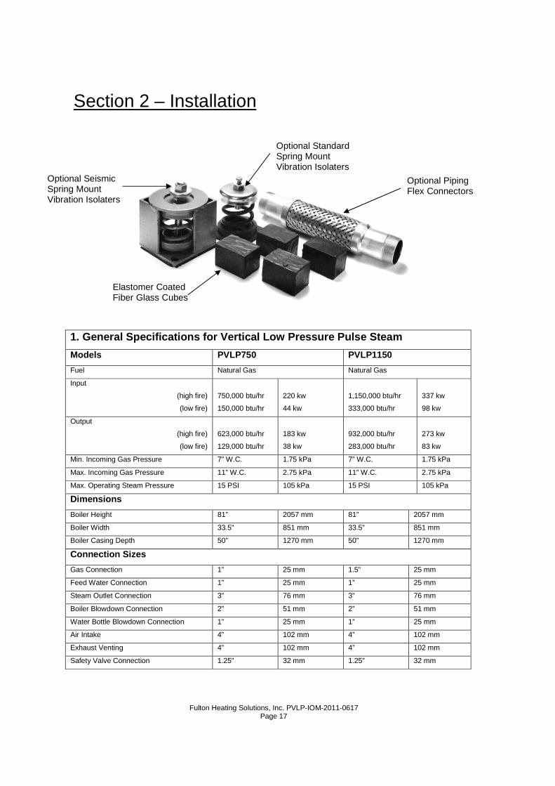
Section 2 – Installation
1. General Specifications for Vertical Low Pressure Pulse Steam
Models PVLP750 PVLP1150
Fuel Natural Gas Natural Gas
Input
(high fire)
(low fire)
750,000 btu/hr
150,000 btu/hr
220 kw
44 kw
1,150,000 btu/hr
333,000 btu/hr
337 kw
98 kw
Output
(high fire)
(low fire)
623,000 btu/hr
129,000 btu/hr
183 kw
38 kw
932,000 btu/hr
283,000 btu/hr
273 kw
83 kw
Min. Incoming Gas Pressure 7” W.C. 1.75 kPa 7” W.C. 1.75 kPa
Max. Incoming Gas Pressure 11” W.C. 2.75 kPa 11” W.C. 2.75 kPa
Max. Operating Steam Pressure 15 PSI 105 kPa 15 PSI 105 kPa
Dimensions
Boiler Height 81” 2057 mm 81” 2057 mm
Boiler Width 33.5” 851 mm 33.5” 851 mm
Boiler Casing Depth 50” 1270 mm 50” 1270 mm
Connection Sizes
Gas Connection 1” 25 mm 1.5” 25 mm
Feed Water Connection 1” 25 mm 1” 25 mm
Steam Outlet Connection 3” 76 mm 3” 76 mm
Boiler Blowdown Connection 2” 51 mm 2” 51 mm
Water Bottle Blowdown Connection 1” 25 mm 1” 25 mm
Air Intake 4” 102 mm 4” 102 mm
Exhaust Venting 4” 102 mm 4” 102 mm
Safety Valve Connection 1.25” 32 mm 1.25” 32 mm
Optional Seismic Spring Mount Vibration Isolaters
Optional Standard Spring Mount Vibration Isolaters
Optional Piping Flex Connectors
Elastomer Coated Fiber Glass Cubes
Fulton Heating Solutions, Inc. PVLP-IOM-2011-0617
Page 18
Approximate Weight
Shipping Weight 2660 lbs 1209 kg 2660 lbs 1209 kg
Operating Weight 3195 lbs 1452 kg 3195 lbs 1452 kg
Floor Load 246 lb/ft2 10.4kg/m2 246 lb/ft2 10.4 kg/m2
Electrical Requirements 4A 120/60/1 4A 120/60/1
Air Intake Piping
Type PVC PVC
Diameter 4” 4"
Length
(min) (max)
10’ 35’
3.05 m 10.67 m
10’ 35’
3.05 m 10.67 m
90 Degree Elbows
(min length) (max length)
0 4
0 4
Clearances
Front 36” 914 mm 36” 914 mm
Left (as viewed from front) 1” 25.5 mm 1” 25.5 mm
Right (as viewed from front) 24” 610 mm 24” 610 mm
Rear 24” 610 mm 24” 610 mm
Clearance Required Above Boiler 24” 610 mm 24” 610 mm
2. Introduction
a) The Fulton pulse combustion low pressure steam boiler is an automatic gas fired,
direct vent boiler. This boiler utilizes the pulse combustion principle. It requires no
conventional burner controls, no pilot and no chimney. The combustion
components are of integral design with the heat exchanger. For combustion, the
boiler uses 100% outside air supplied through schedule 40 PVC pipe. The products
of combustion are vented outdoors through non-corrosive venting materials, which
will withstand 480°F (249°C) temperatures. These pi pes can be routed either
through a roof or through the side wall of a building.
b) The Fulton PVLP Steam Boiler is designed for use in a closed loop (>75%
condensate return) steam application.
c) Each boiler is built to ASME and CSD-1 Codes, hydrostatically tested, test fired,
and shipped as a complete packaged unit. Gas, water, and electrical connections
are similar to conventional boilers.
d) All installations must be in accordance with the American National Standard
“National Fuel Gas Code,” latest edition, and with the requirements of local utilities
or other authorities having jurisdiction. Such applicable requirements take
precedence over the general instructions herein.
e) Since an external electrical source is utilized, the boiler, when installed, must be
electrically grounded in accordance with the National Electrical Code, ANSI/NFPA
70-latest edition.
Fulton Heating Solutions, Inc. PVLP-IOM-2011-0617
Page 19
f) In some cases the approval authority may insist that the installation conform to the
American Society of Mechanical Engineers ASME safety standard for controls and
safety devices for automatically fired boilers, or CSD-1.
g) In Canada, gas installations must be in accordance with the current CAN/CGA
B149.1 and .2 and/or local codes. Electrical installations must be installed in
accordance with the current CSA C22.1 Canadian Electrical Code and/or local
codes.
3. The following items are standard trim for Fulton Pulse Combustion
Low Pressure Steam Boilers:
a) Fully Insulated
b) Microprocessor Based Control - 120 volt
c) Water Level Probes
d) Control Panel Completely Wired with Diagram
e) Operating Pressure Control
f) Hi-Limit Pressure Control w/ Manual Reset
g) Air Pressure Switch
h) Spark Ignition
i) Main Motorized Gas Valve
j) Main Gas Pressure Regulator
k) Manual Lubricated Gas Cock
l) Second Gas Valve (Solenoid)
m) Pump Water Level Relay
1. (Probe Type) with Starter Relay
2. (Single Phase)
4. Recommended Water Conditions
a) Following are recommendations for feed water and boiler water. Contact your local
water treatment professional for testing and treatment recommendations. It is very
important that a strict water treatment program be followed.
b) It is critical that the boiler pH follow the attached schedule whenever water is in the
boiler. Solids that enter in with the feed water will concentrate in the boiler. A
regular schedule of boiler blowdown must be maintained to prevent high solid
concentrations from corroding the vessel or forming deposits.
Fulton Heating Solutions, Inc. PVLP-IOM-2011-0617
Page 20
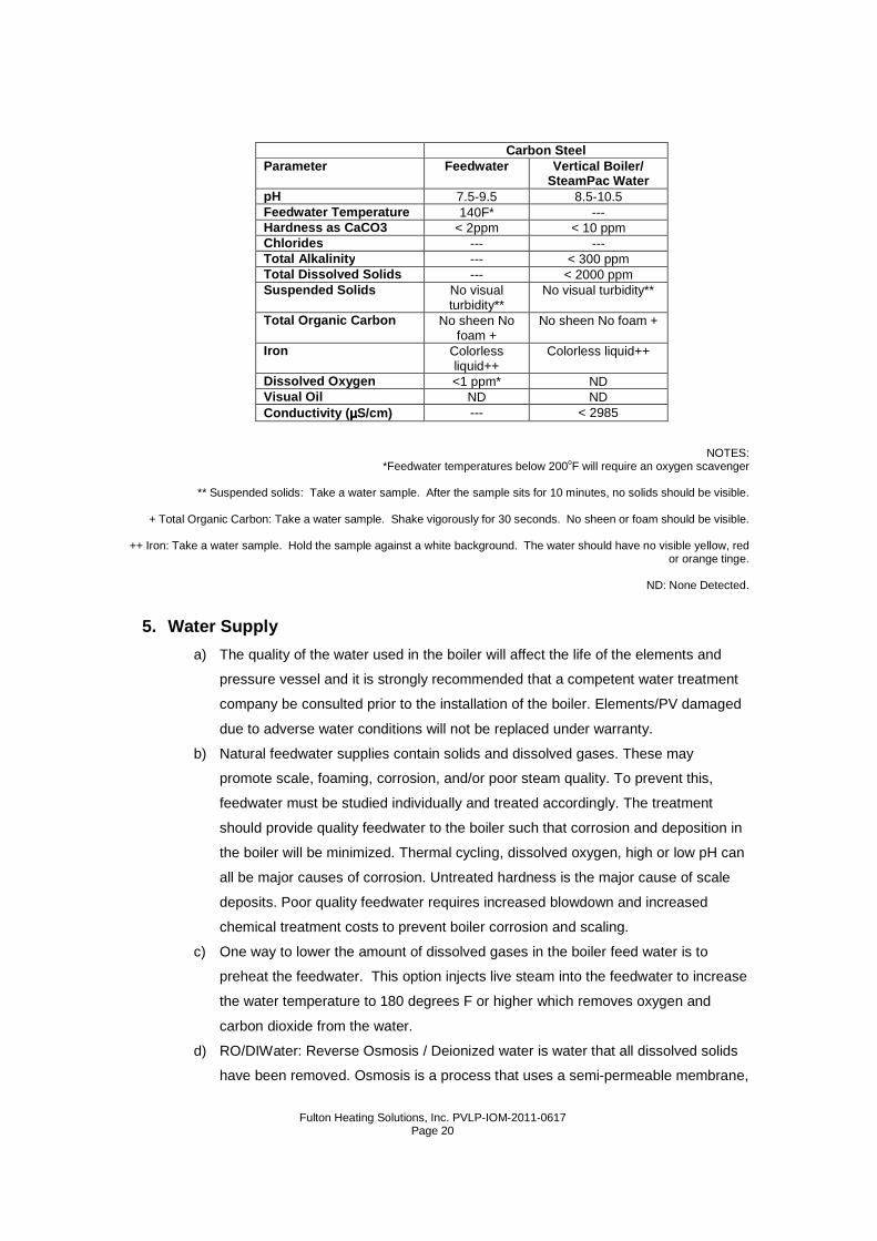
Carbon Steel Parameter Feedwater Vertical Boiler/
SteamPac Water pH 7.5-9.5 8.5-10.5 Feedwater Temperature 140F* --- Hardness as CaCO3 < 2ppm < 10 ppm Chlorides --- --- Total Alkalinity --- < 300 ppm Total Dissolved Solids --- < 2000 ppm Suspended Solids No visual
turbidity** No visual turbidity**
Total Organic Carbon No sheen No foam +
No sheen No foam +
Iron Colorless liquid++
Colorless liquid++
Dissolved Oxygen <1 ppm* ND Visual Oil ND ND Conductivity ( µµµµS/cm) --- < 2985
NOTES: *Feedwater temperatures below 200oF will require an oxygen scavenger
** Suspended solids: Take a water sample. After the sample sits for 10 minutes, no solids should be visible.
+ Total Organic Carbon: Take a water sample. Shake vigorously for 30 seconds. No sheen or foam should be visible.
++ Iron: Take a water sample. Hold the sample against a white background. The water should have no visible yellow, red
or orange tinge.
ND: None Detected.
5. Water Supply
a) The quality of the water used in the boiler will affect the life of the elements and
pressure vessel and it is strongly recommended that a competent water treatment
company be consulted prior to the installation of the boiler. Elements/PV damaged
due to adverse water conditions will not be replaced under warranty.
b) Natural feedwater supplies contain solids and dissolved gases. These may
promote scale, foaming, corrosion, and/or poor steam quality. To prevent this,
feedwater must be studied individually and treated accordingly. The treatment
should provide quality feedwater to the boiler such that corrosion and deposition in
the boiler will be minimized. Thermal cycling, dissolved oxygen, high or low pH can
all be major causes of corrosion. Untreated hardness is the major cause of scale
deposits. Poor quality feedwater requires increased blowdown and increased
chemical treatment costs to prevent boiler corrosion and scaling.
c) One way to lower the amount of dissolved gases in the boiler feed water is to
preheat the feedwater. This option injects live steam into the feedwater to increase
the water temperature to 180 degrees F or higher which removes oxygen and
carbon dioxide from the water.
d) RO/DIWater: Reverse Osmosis / Deionized water is water that all dissolved solids
have been removed. Osmosis is a process that uses a semi-permeable membrane,
Fulton Heating Solutions, Inc. PVLP-IOM-2011-0617
Page 21
under pressure, to reject dissolved salts and allow water to pass through. When a
solution of salt and water is separated by a membrane, the osmotic pressure forces
the water through the membrane, diluting the salt solution. When pressure greater
than osmotic pressure is applied to the salt solution, the membrane allows the
water from the salt solution to pass into the water solution and rejects the dissolved
salts. The osmotic process is reversed, hence, reverse osmosis. RO/DI water has
no buffering capacity and a pH of <6.5. It is corrosive to carbon steel, however, not
to stainless steel. Very high purity steam quality can be obtained with RO/DI water.
e) Electric boiler and unfired steam generators’ pressure vessels made from carbon
steel that use RO/DI water for the supply water will require pH neutralization for
vessel longevity. Electric boilers and unfired steam generators with stainless steel
pressure vessels do not require pH neutralization. ASME Code allows electric
boilers to be manufactured with stainless steel pressure vessels provided RO/DI
water is used as the water supply.
f) The Fulton Warranty does not cover damage or failure that can be attributed to
corrosion, scale or fouling.
6. Glossary of Water Supply Terms
a) Dissolved Oxygen : Oxygen that is dissolved in the feedwater will cause the steel
in the boiler and the feedwater system to be attacked by the water in a manner
described as “pitting”. The pits that are produced can vary from tiny depressions to
holes large enough to penetrate the boiler metal and are usually covered with
tubercles of iron oxide. Once pitting starts, it may be extremely hard to arrest.
Pitting can proceed at a surprisingly rapid rate and can occur not only in the boiler
proper, but also in pre-boiler equipment such as ecomomizers, feedwater tanks,
and feedwater lines.
b) Sodium Sulfite : Its purpose is to chemically remove the dissolved oxygen left in
the feedwater after the feedwater has been mechanically deareated. Sodium
Sulfite reacts chemically with dissolved oxygen, producing sodium sulfate. Since it
is desirable to remove dissolved oxygen from the feedwater before it reaches a
boiler. Sodium sulfite is best introduced continuously at some suitable point in the
feedwater system (the storage section of the feedwater heater or deareator, six
inches below the water line). Chemical residual control is based on the
maintenance of a specific excess of sodium sulfite in the boiler water. The essential
requirement being to maintain in the feedwater at all times slightly more than
enough sodium sulfite to consume all of the dissolved oxygen that slips through the
deareating equipment. Sulfite as a treatment represents the second line of defense
against oxygen corrosion. Primary protection against this type of attack requires
Fulton Heating Solutions, Inc. PVLP-IOM-2011-0617
Page 22
adequate facilities for mechanical deareation of the feed-water plus a vigorous
maintenance program to safe guard against oxygen leakage into the pre-boiler
system.
c) Suspended Solids : Suspended solids are the undissolved matter in water, inc-
luding dirt, silt, vegetation, iron oxides, and any other insoluble matter. Normally
suspended solids are expressed in terms of turbidity. Suspended solids may also
deposit in low velocity areas and create fouling. In line filters, or various types of
pretreatment can be used to lower the suspended solids level. Various polymers
assist in holding solids in suspension. Periodic blowdowns will eliminate
suspended solids.
d) Alkalinity : Alkalinity is the capacity of a water to neutralize acids. Common water
alkalinities consist of bicarbonate, carbonates, hydroxide, phosphate, and silicate.
These alkalinities, especially bicarbonates and carbonates, break down to form
carbon dioxide in steam, which is a major factor in the corrosion on condensate
lines. High alkalinity also causes foaming and carry over in boilers. Both foaming
and carry over cause erratic boiler operation. When foaming occurs an antifoam
should be added or increased. The reason for the high alkalinity should be
determined. It may result from lack of sufficient blow off. Quite often the source of
alkalinity is an overdose of alkaline internal water treatment chemical.
e) pH: pH is a measure of the degree of acid or base of solution. pH ranges of 8.0-
10.5 will have little influence on the corrosion rate of carbon steel. A low pH can
result in corrosion of metals, while a high pH can result in scale formation or
caustic embrittlement. In order to control boilers and equipment used for the
external treatment of make up water, it is essential that reliable pH measurements
be made. RO/DI water will have a pH of 6.0 - 6.5 and will require neutralization if
used in a carbon steel vessel.
f) Chlorides : If chloride levels are high enough to cause severe corrosion, they can
be controlled by limiting the cycles of concentration and increasing boiler
blowdowns. Corrosion from chlorides can also be controlled by increasing the
amount of corrosion inhibitor or changing to a more effective inhibitor. Reverse
osmosis is another method of pretreatment to reduce chlorides. Chlorides are a
major concern in a stainless steel vessel.
g) Oil : Oil is not a natural constituent of boiler water; still it can frequently enter a
system through leaks in a condenser or other heat exchanger. Oil can also enter a
system through the lubrication of steam driven reciprocating equipment. Whatever
the source, the presence of oil in boiler water is undesirable. Oil can act as a binder
to form scale. In high heat-transfer areas oil can carbonize and further contribute
to the formation of scale and low pH. Foaming is one indication of oil in boiler
Fulton Heating Solutions, Inc. PVLP-IOM-2011-0617
Page 23
water. Its presence can also be confirmed by first shaking a bottle containing boiler
water. If oil is present foam will result. Often oil in boiler water will originate in the
condensate. This contaminated condensate should be directed to the sewer until
the source of the oil is determined and corrective steps taken.
h) Iron (oxides): Iron in any of its oxide or complex forms is undesirable in boiler
water. Iron in its various forms can originate in the raw water makeup, condensate
return water, or form directly in the boiler as a result of corrosion. It can
concentrate in the boiler and it tends to collect in stagnant areas. If a boiler is
using raw water makeup, iron is almost certain to be a major component of
developing scale or create fouling.
i) Water Hardness : Water hardness is the measure of calcium and magnesium
content as calcium carbonate equivalents. Water hardness is a primary source of
scale in boiler equipment. Hardness is removed by softening.
j) Feedwater : Feedwater is the combination of fresh makeup and returning
condensate that is pumped to the boiler.
k) Condensate: Condensate is condensed steam that is normally low in dissolved
solids. Hence, it does not contribute to the dissolved solid content of the
feedwater. In addition, condensate is very expensive to waste. It's been
chemically treated, heated, pumped, converted to steam, and condensed. This
costs money and when condensate is returned to the boiler, money is saved.
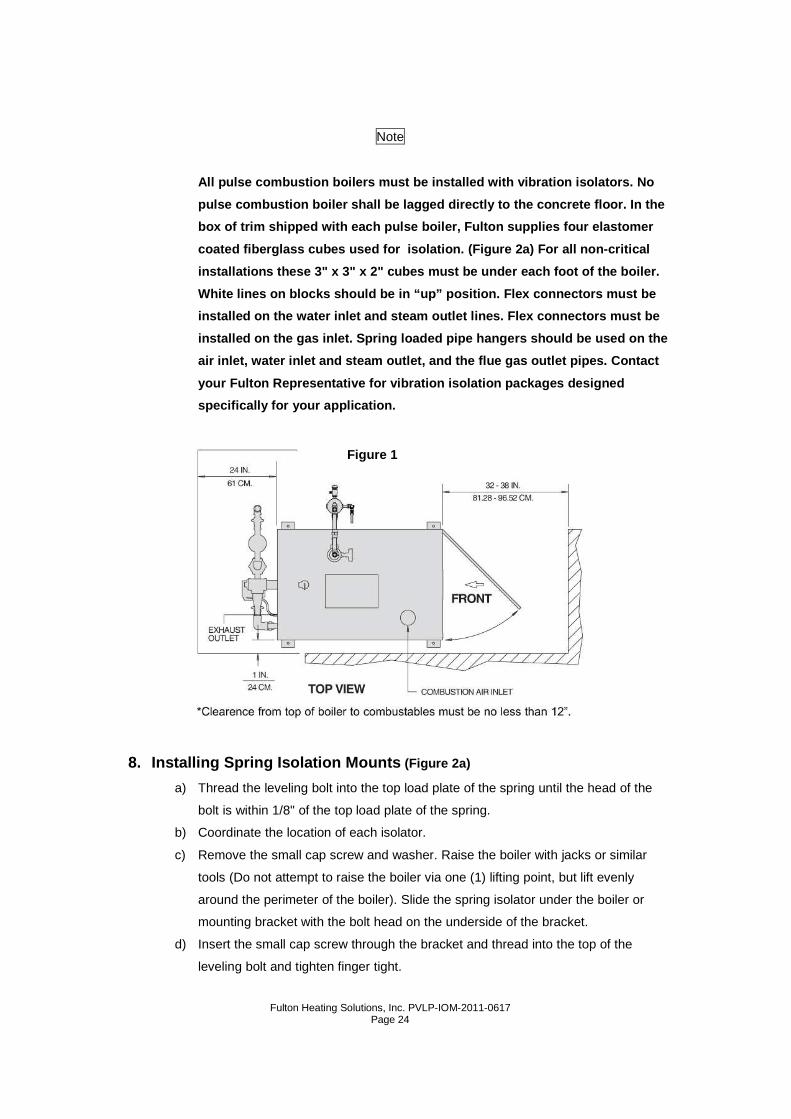
7. Locating the Boiler
a) The boiler shall be located so that the air supply and exhaust piping between the
boiler and outside wall/roof are within the minimum and maximum lengths for
horizontal or vertical venting. See Figure 1 for minimum clearances between the
boiler and any combustible surfaces.
Note
The boiler must not be installed on carpeting.
Note
The boiler shall be installed such that the gas ign ition system components
are protected from water (dripping, spraying, rain, etc.) during boiler
operation and service.
Fulton Heating Solutions, Inc. PVLP-IOM-2011-0617
Page 24
Note
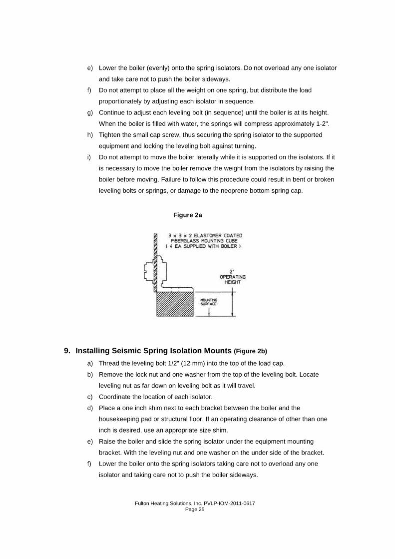
All pulse combustion boilers must be installed with vibration isolators. No
pulse combustion boiler shall be lagged directly to the concrete floor. In the
box of trim shipped with each pulse boiler, Fulton supplies four elastomer
coated fiberglass cubes used for isolation. (Figur e 2a) For all non-critical
installations these 3" x 3" x 2" cubes must be unde r each foot of the boiler.
White lines on blocks should be in “up” position. F lex connectors must be
installed on the water inlet and steam outlet lines . Flex connectors must be
installed on the gas inlet. Spring loaded pipe hang ers should be used on the
air inlet, water inlet and steam outlet, and the fl ue gas outlet pipes. Contact
your Fulton Representative for vibration isolation packages designed
specifically for your application.
8. Installing Spring Isolation Mounts (Figure 2a)
a) Thread the leveling bolt into the top load plate of the spring until the head of the
bolt is within 1/8" of the top load plate of the spring.
b) Coordinate the location of each isolator.
c) Remove the small cap screw and washer. Raise the boiler with jacks or similar
tools (Do not attempt to raise the boiler via one (1) lifting point, but lift evenly
around the perimeter of the boiler). Slide the spring isolator under the boiler or
mounting bracket with the bolt head on the underside of the bracket.
d) Insert the small cap screw through the bracket and thread into the top of the
leveling bolt and tighten finger tight.
Figure 1
Fulton Heating Solutions, Inc. PVLP-IOM-2011-0617
Page 25
e) Lower the boiler (evenly) onto the spring isolators. Do not overload any one isolator
and take care not to push the boiler sideways.
f) Do not attempt to place all the weight on one spring, but distribute the load
proportionately by adjusting each isolator in sequence.
g) Continue to adjust each leveling bolt (in sequence) until the boiler is at its height.
When the boiler is filled with water, the springs will compress approximately 1-2".
h) Tighten the small cap screw, thus securing the spring isolator to the supported
equipment and locking the leveling bolt against turning.
i) Do not attempt to move the boiler laterally while it is supported on the isolators. If it
is necessary to move the boiler remove the weight from the isolators by raising the
boiler before moving. Failure to follow this procedure could result in bent or broken
leveling bolts or springs, or damage to the neoprene bottom spring cap.
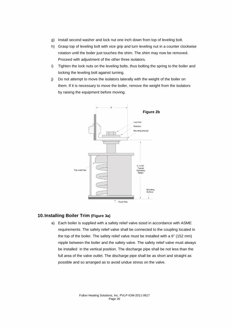
9. Installing Seismic Spring Isolation Mounts (Figure 2b)
a) Thread the leveling bolt 1/2" (12 mm) into the top of the load cap.
b) Remove the lock nut and one washer from the top of the leveling bolt. Locate
leveling nut as far down on leveling bolt as it will travel.
c) Coordinate the location of each isolator.
d) Place a one inch shim next to each bracket between the boiler and the
housekeeping pad or structural floor. If an operating clearance of other than one
inch is desired, use an appropriate size shim.
e) Raise the boiler and slide the spring isolator under the equipment mounting
bracket. With the leveling nut and one washer on the under side of the bracket.
f) Lower the boiler onto the spring isolators taking care not to overload any one
isolator and taking care not to push the boiler sideways.
Figure 2a
Fulton Heating Solutions, Inc. PVLP-IOM-2011-0617
Page 26
g) Install second washer and lock nut one inch down from top of leveling bolt.
h) Grasp top of leveling bolt with vice grip and turn leveling nut in a counter clockwise
rotation until the boiler just touches the shim. The shim may now be removed.
Proceed with adjustment of the other three isolators.
i) Tighten the lock nuts on the leveling bolts, thus bolting the spring to the boiler and
locking the leveling bolt against turning.
j) Do not attempt to move the isolators laterally with the weight of the boiler on
them. If it is necessary to move the boiler, remove the weight from the isolators
by raising the equipment before moving.
10. Installing Boiler Trim (Figure 3a)
a) Each boiler is supplied with a safety relief valve sized in accordance with ASME
requirements. The safety relief valve shall be connected to the coupling located in
the top of the boiler. The safety relief valve must be installed with a 6" (152 mm)
nipple between the boiler and the safety valve. The safety relief valve must always
be installed in the vertical position. The discharge pipe shall be not less than the
full area of the valve outlet. The discharge pipe shall be as short and straight as
possible and so arranged as to avoid undue stress on the valve.
Figure 2b
Fulton Heating Solutions, Inc. PVLP-IOM-2011-0617
Page 27
Warning
The discharge from safety relief valve shall be so arranged that there will be
no danger of scalding of personnel.
When the safety relief valve discharge is piped awa y from the boiler to the
point of discharge, there shall be provisions made for properly draining the
piping.
Warning
No shutoff of any kind shall be placed between the safety relief valve and the
boiler or on the discharge pipe between such valve and the atmosphere.
Doing so can cause an accidental explosion from ove r-pressure.
b) Each boiler is supplied with a pressure-temperature gauge. A nipple is installed in
the boiler water outlet. A tee is installed on the nipple. In the side port of the tee the
temperature gauge is installed.
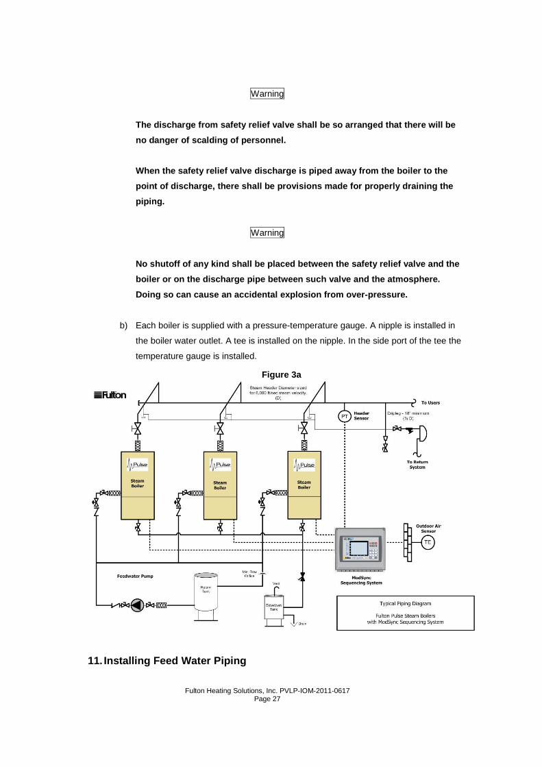
11. Installing Feed Water Piping
Figure 3a
Fulton Heating Solutions, Inc. PVLP-IOM-2011-0617
Page 28
a) Connect the factory supplied feedwater stop valve to the feed water inlet
connection at the boiler as shown on the rear of boiler and then connect the factory
supplied check valve (upstream) to the stop valve. A second check valve is
recommended (supplied by others).
b) Installing steam piping, pipe the steam supply away from the steam outlet
connection. There should be a 2” (51 mm) clearance around all steam piping.
Steam pipes should be insulated to minimize system losses.
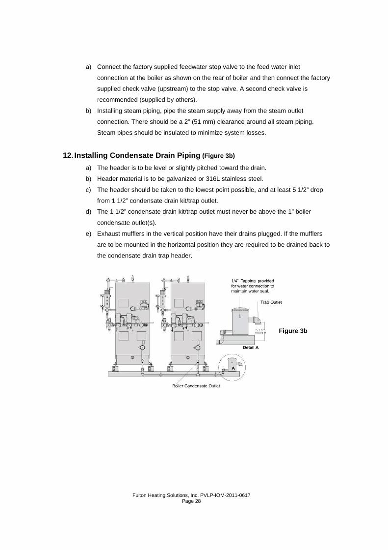
12. Installing Condensate Drain Piping (Figure 3b)
a) The header is to be level or slightly pitched toward the drain.
b) Header material is to be galvanized or 316L stainless steel.
c) The header should be taken to the lowest point possible, and at least 5 1/2” drop
from 1 1/2” condensate drain kit/trap outlet.
d) The 1 1/2” condensate drain kit/trap outlet must never be above the 1” boiler
condensate outlet(s).
e) Exhaust mufflers in the vertical position have their drains plugged. If the mufflers
are to be mounted in the horizontal position they are required to be drained back to
the condensate drain trap header.
Figure 3b
Fulton Heating Solutions, Inc. PVLP-IOM-2011-0617
Page 29
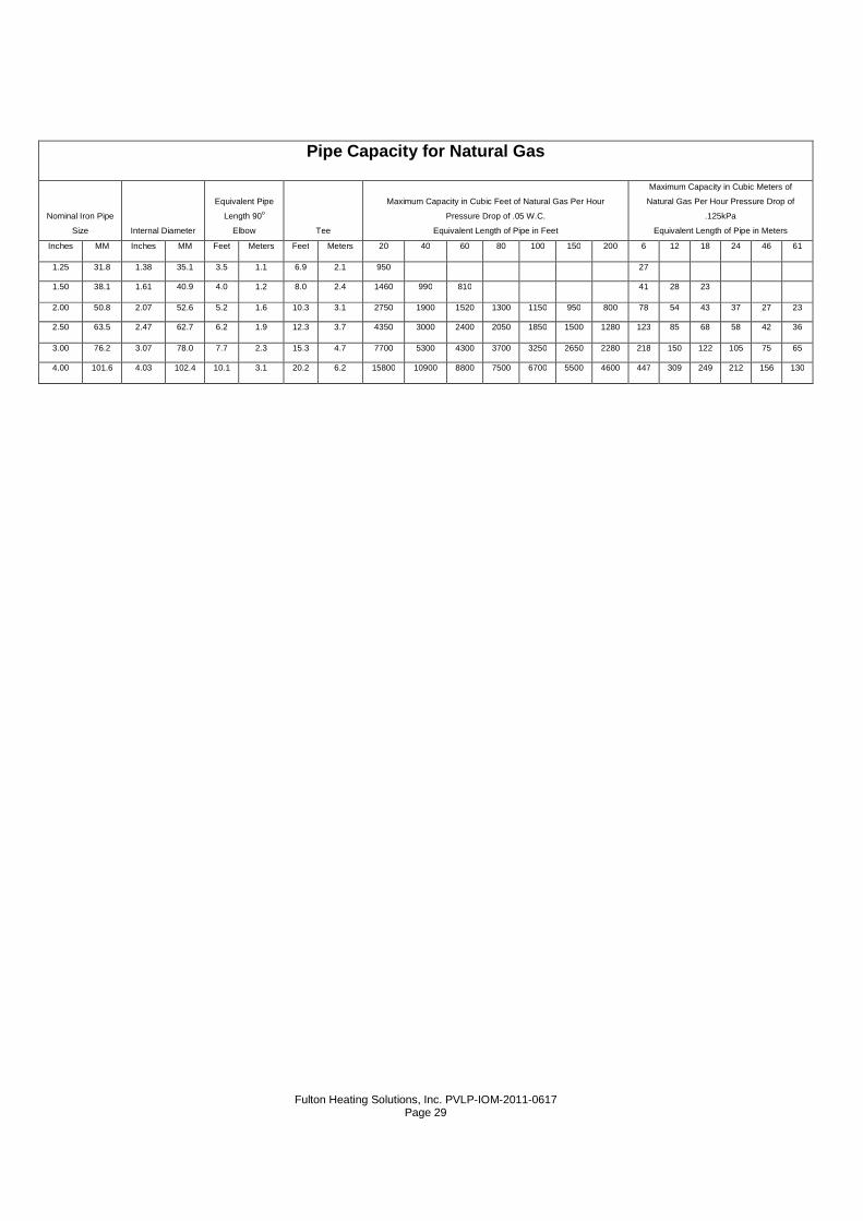
Pipe Capacity for Natural Gas
Nominal Iron Pipe
Size Internal Diameter
Equivalent Pipe
Length 90o
Elbow Tee
Maximum Capacity in Cubic Feet of Natural Gas Per Hour
Pressure Drop of .05 W.C.
Equivalent Length of Pipe in Feet
Maximum Capacity in Cubic Meters of
Natural Gas Per Hour Pressure Drop of
.125kPa
Equivalent Length of Pipe in Meters
Inches MM Inches MM Feet Meters Feet Meters 20 40 60 80 100 150 200 6 12 18 24 46 61
1.25 31.8 1.38 35.1 3.5 1.1 6.9 2.1 950 27
1.50 38.1 1.61 40.9 4.0 1.2 8.0 2.4 1460 990 810 41 28 23
2.00 50.8 2.07 52.6 5.2 1.6 10.3 3.1 2750 1900 1520 1300 1150 950 800 78 54 43 37 27 23
2.50 63.5 2.47 62.7 6.2 1.9 12.3 3.7 4350 3000 2400 2050 1850 1500 1280 123 85 68 58 42 36
3.00 76.2 3.07 78.0 7.7 2.3 15.3 4.7 7700 5300 4300 3700 3250 2650 2280 218 150 122 105 75 65
4.00 101.6 4.03 102.4 10.1 3.1 20.2 6.2 15800 10900 8800 7500 6700 5500 4600 447 309 249 212 156 130
Fulton Heating Solutions, Inc. PVLP-IOM-2011-0617
Page 30
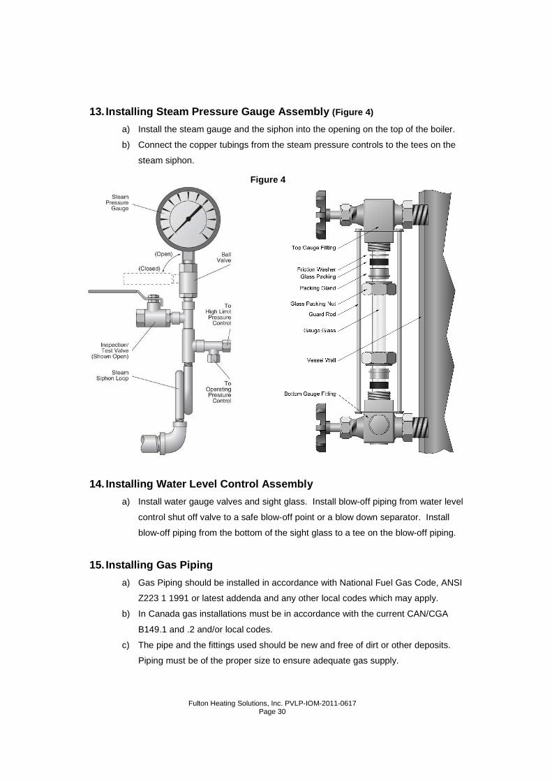
13. Installing Steam Pressure Gauge Assembly (Figure 4)
a) Install the steam gauge and the siphon into the opening on the top of the boiler.
b) Connect the copper tubings from the steam pressure controls to the tees on the
steam siphon.
14. Installing Water Level Control Assembly
a) Install water gauge valves and sight glass. Install blow-off piping from water level
control shut off valve to a safe blow-off point or a blow down separator. Install
blow-off piping from the bottom of the sight glass to a tee on the blow-off piping.
15. Installing Gas Piping
a) Gas Piping should be installed in accordance with National Fuel Gas Code, ANSI
Z223 1 1991 or latest addenda and any other local codes which may apply.
b) In Canada gas installations must be in accordance with the current CAN/CGA
B149.1 and .2 and/or local codes.
c) The pipe and the fittings used should be new and free of dirt or other deposits.
Piping must be of the proper size to ensure adequate gas supply.
Figure 4
Fulton Heating Solutions, Inc. PVLP-IOM-2011-0617
Page 31
d) Gas pressure to inlet of gas train should be 7"-11” WC. (1.75-2.75 kPa) for natural
gas. Connect gas supply line to the open end of the tee on which the drip leg is
installed.
e) When making gas piping joints, use a sealing compound resistant to the action of
liquefied petroleum gases. Do not use Teflon tape on gas line threads.
f) After gas piping is completed and before wiring installation is started, carefully
check all piping connections, (factory and field), for gas leaks. Use a soap and
water solution.
Caution
Some soaps used for leak testing are corrosive to c ertain types of metals.
Rinse all piping thoroughly with clean water after leak check has been
completed.
g) The boiler must be disconnected at the boiler shut off valve from the gas supply
piping system during any pressure testing of the system at pressure in excess of
1/2 psig (14" WC) (3.5 kPa).
h) The boiler must be isolated from the gas supply piping system by closing its
individual manual shut off valve during any pressure testing of the gas supply
system at test pressures equal or less than 1/2psi (3.5kPa).
i) Gas vents to outdoor air must be provided for the pressure regulator and gas
pressure switches. Restricting orifices or bleed orifices should not be used at
anytime.
Warning
Do not use matches, candles, flame or other sources of ignition to check for
gas Ieaks.
Note
The vent line connection on the gas pressure regula tor and the low and high
gas pressure switches must be piped to outdoor air by installer in
accordance with the National Fuel Gas Code, ANSI Z 223 1 1991 or latest
addenda.
In Canada gas installations must be in accordance w ith the current CAN/CGA
Fulton Heating Solutions, Inc. PVLP-IOM-2011-0617
Page 32
B149.1 and .2 and/or local codes.
Please refer to the drawings in the back of this manual.
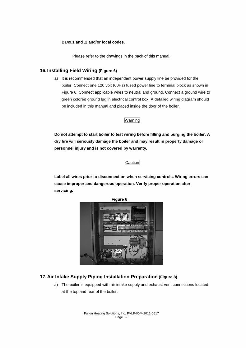
16. Installing Field Wiring (Figure 6)
a) It is recommended that an independent power supply line be provided for the
boiler. Connect one 120 volt (60Hz) fused power line to terminal block as shown in
Figure 6. Connect applicable wires to neutral and ground. Connect a ground wire to
green colored ground lug in electrical control box. A detailed wiring diagram should
be included in this manual and placed inside the door of the boiler.
Warning
Do not attempt to start boiler to test wiring befor e filling and purging the boiler. A
dry fire will seriously damage the boiler and may r esult in property damage or
personnel injury and is not covered by warranty.
Caution
Label all wires prior to disconnection when servici ng controls. Wiring errors can
cause improper and dangerous operation. Verify prop er operation after
servicing.
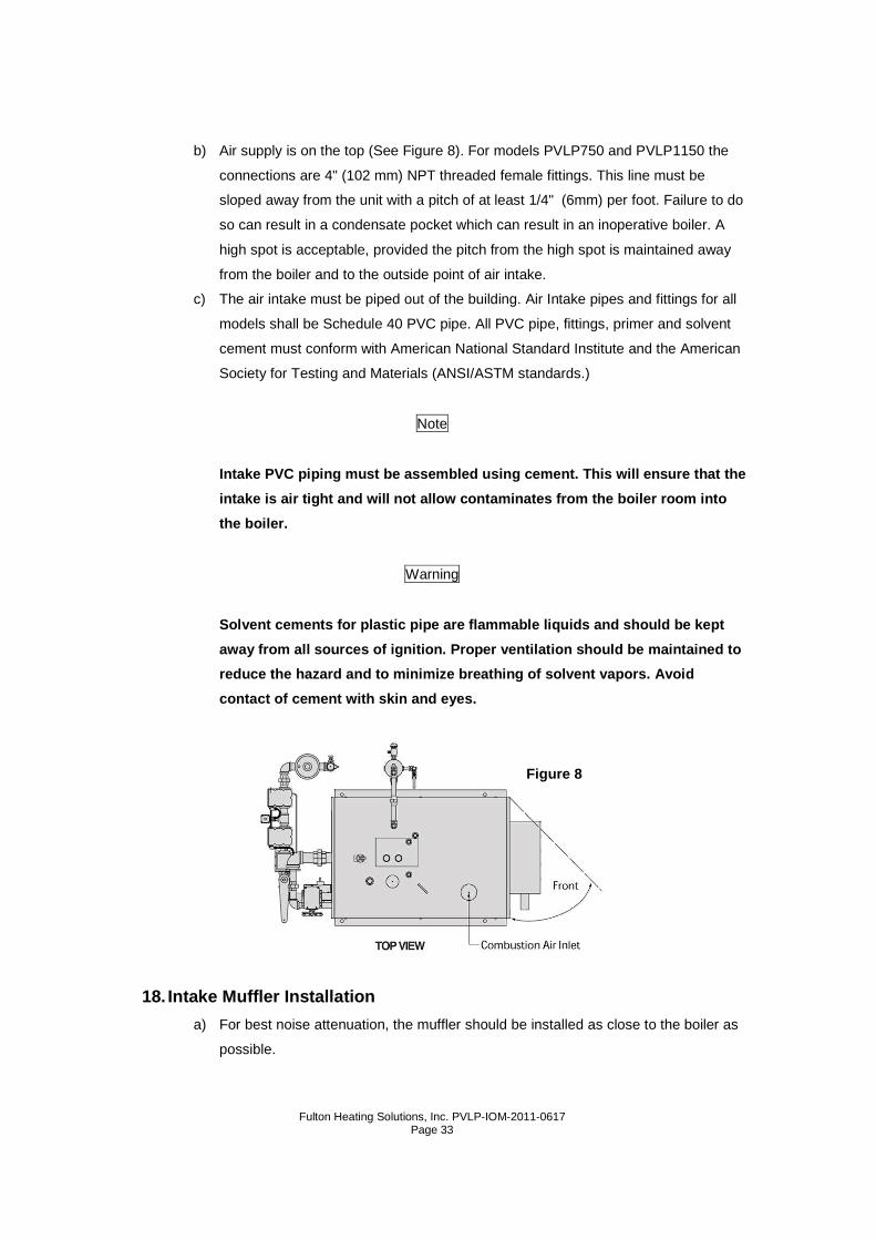
17. Air Intake Supply Piping Installation Preparati on (Figure 8)
a) The boiler is equipped with air intake supply and exhaust vent connections located
at the top and rear of the boiler.
Figure 6
Fulton Heating Solutions, Inc. PVLP-IOM-2011-0617
Page 33
b) Air supply is on the top (See Figure 8). For models PVLP750 and PVLP1150 the
connections are 4" (102 mm) NPT threaded female fittings. This line must be
sloped away from the unit with a pitch of at least 1/4" (6mm) per foot. Failure to do
so can result in a condensate pocket which can result in an inoperative boiler. A
high spot is acceptable, provided the pitch from the high spot is maintained away
from the boiler and to the outside point of air intake.
c) The air intake must be piped out of the building. Air Intake pipes and fittings for all
models shall be Schedule 40 PVC pipe. All PVC pipe, fittings, primer and solvent
cement must conform with American National Standard Institute and the American
Society for Testing and Materials (ANSI/ASTM standards.)
Note
Intake PVC piping must be assembled using cement. T his will ensure that the
intake is air tight and will not allow contaminates from the boiler room into
the boiler.
Warning
Solvent cements for plastic pipe are flammable liqu ids and should be kept
away from all sources of ignition. Proper ventilati on should be maintained to
reduce the hazard and to minimize breathing of solv ent vapors. Avoid
contact of cement with skin and eyes.
18. Intake Muffler Installation
a) For best noise attenuation, the muffler should be installed as close to the boiler as
possible.
Figure 8
Fulton Heating Solutions, Inc. PVLP-IOM-2011-0617
Page 34
19. Exhaust Vent Piping Installation Preparation
Note
A Fulton PVLP boiler should not be connected to a c ommon venting system
with other types of gas appliances.
a) The boiler is equipped with an exhaust vent connection located at the rear of the
boiler. (Figure 10) For models PVLP750 and PVLP1150 the connections are 4"
(102mm) NPT threaded female fittings.
b) The exhaust line must be sloped down toward the unit with a pitch of at least 1/4"
(6mm) per foot. Failure to do so can result in a condensate pocket which can result
in an inoperative boiler. There must be no low spots in the exhaust pipe, as this
can also result in a condensate pocket. A high spot is acceptable, provided the
pitch from the high spot is maintained back to the boiler to the outside point of the
exhaust.
c) In supporting piping, or routing it through a rafter or wall, always use vibration
eliminating hangers around the piping to prevent transmission of pulsations.
Always avoid rigid connections between piping and structural members of the
building. Flue exhaust pipes and fittings for all models shall be stainless steel. The
stainless steel shall be UL temperature rated at minimum air clearance to
combustibles. At 480°F (249°C) temperature rating, a 5" (127mm) minimum air
space clearance to combustibles is required. Fulton pulse combustion boilers
require a special venting system. Applicable Federal Codes are NFPA 54/ANSI
Z223.1 National Fuel Gas Code and NFPA/ANSI 211 Chimneys, Fireplaces, Vents,
and Solid Fuel Burning Appliances. In Canada refer to the venting section of
CAN/CGA B149.1 and .2. These codes contain information on special gas vents.
The gas vent installer should be familiar with these Federal Codes as well as local
codes and regulations.
20. Exhaust Muffler Installation
a) For mufflers installed in the vertical configuration the drain can be plugged.
b) For mufflers installed in the horizontal configuration, the drain should be piped to
the drain line between the boiler and the liquid drainer. For best noise attenuation,
the muffler should be installed as close to the boiler as possible.
Fulton Heating Solutions, Inc. PVLP-IOM-2011-0617
Page 35
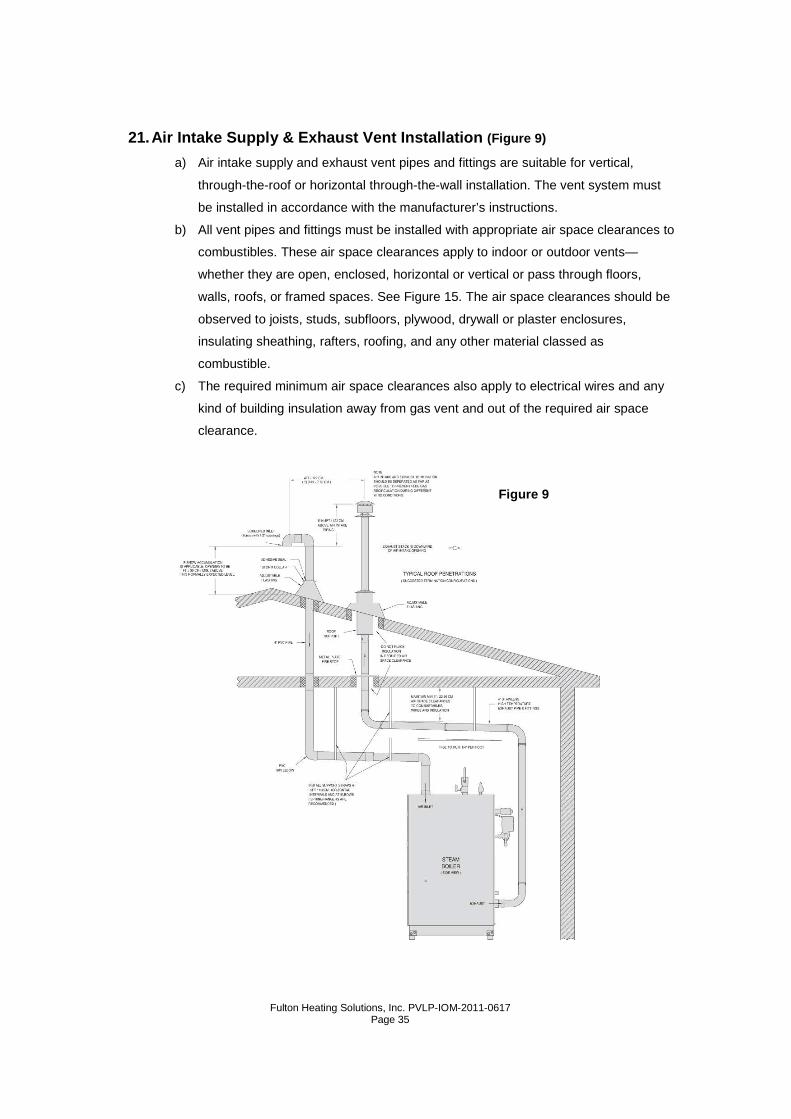
21. Air Intake Supply & Exhaust Vent Installation (Figure 9)
a) Air intake supply and exhaust vent pipes and fittings are suitable for vertical,
through-the-roof or horizontal through-the-wall installation. The vent system must
be installed in accordance with the manufacturer’s instructions.
b) All vent pipes and fittings must be installed with appropriate air space clearances to
combustibles. These air space clearances apply to indoor or outdoor vents—
whether they are open, enclosed, horizontal or vertical or pass through floors,
walls, roofs, or framed spaces. See Figure 15. The air space clearances should be
observed to joists, studs, subfloors, plywood, drywall or plaster enclosures,
insulating sheathing, rafters, roofing, and any other material classed as
combustible.
c) The required minimum air space clearances also apply to electrical wires and any
kind of building insulation away from gas vent and out of the required air space
clearance.
Figure 9
Fulton Heating Solutions, Inc. PVLP-IOM-2011-0617
Page 36
d) Vertical runs or vent pipes and fittings passing through floors, ceilings, or in framed
walls must be fire stopped at floors and ceilings. The fire stop must close in the
area between the outside of the vent and the opening in the structure.
e) Figure 11: When passing through a floor or ceiling, frame in an opening providing
5" (127 mm) or 9" (229 mm) air space clearance to vent pipe as applicable. The fire
stop fits to the bottom of a framed opening 13 1/4 " (337 mm) square. Nail into the
inside of the framed opening through the four holes in the ring. The fire stop is
placed on top of a framed opening 14 1/4 " (362 mm) square with the dished
position down. Nail the flange to the top of the framing. For pitched roofs refer to
Figure 13.
f) Pass the vent pipe through the opening in the fire stop. If used as a support, install
the support ring around the vent pipe above the fire stop. Slide the support ring
down to the top of the fire stop and tighten it securely to the vent pipe. Firestop
supports can support up to 10 feet (3 meters) of vent pipes and are recommended
at all floor and ceiling penetrations.
Figure 11: Air intake supply and exhaust vent pipes and fittings must be securely
supported. For pitched roofs refer to Figure 13.
g) Horizontal sections require supports every 5 feet (15 meters) and at elbows. From
the boiler, all horizontal sections must rise at least 1/4 " per foot (2 cm per meter),
and there must be no sags or dips where condensate could collect. The upward
pitch is required so condensate will run back to the boiler for collection and
disposal.
h) For vertical through the roof installations all gas vents extending above the roof by
more than 2 1/2 feet (0.76 m) must be securely guyed or braced—inside and
outside wall—2 clamps. Use a support ring to attach guys or braces to the vent
pipe.
Figure 10
Figure 11
Fulton Heating Solutions, Inc. PVLP-IOM-2011-0617
Page 37
22. Vertical Vent Flashing & Installation (Figure 12)
a) The roof opening should be located and sized such that the vent is vertical and has
the required air space clearance. The roof flashing is positioned with the lower
portion of the base flange over roofing material.
b) Nail through the upper portion and sides of the base flange. Use nails with
neoprene washers or cover the nail heads with a neoprene plastic. Finish roofing
around that flashing, covering the sides and upper flange with roofing material.
23. Vertical Vent Termination
a) The vent pipe must extend through the flashing to a height above the roof as
required in Figure 13.
b) A storm collar is installed on the vent pipe over the opening between pipe and
flashing. Adhesive material is used over the joint between the vent pipe and the
storm collar.
c) Figure 13: The vent termination is joined to the end of the vent pipe.
d) Termination height for the vent pipe must be such that no discharge opening is less
than 2 feet horizontally from the roof surface, and no discharge opening shall be
lower than the minimum height specified in Figure 13. These minimum heights may
be used provided the vent is not less than 8 feet (2-44m) from any vertical wall.
Figure 12
Fulton Heating Solutions, Inc. PVLP-IOM-2011-0617
Page 38
Figure 13
Fulton Heating Solutions, Inc. PVLP-IOM-2011-0617
Page 39
24. Horizontal Installation Wall Penetrations (Figure 14)
a) Select the point of penetration where a minimum of 1/4" per foot (2 cm per meter)
upward pitch can be maintained.
b) When penetrating a non-combustible wall, the hole through the wall must be large
enough to maintain the pitch of the vent and provide sealing. Use adhesive
material to seal around the vent on both sides of the wall.
c) When penetrating a combustible wall, a wall thimble must be used. See next page
Figure 15 for installation instructions.
d) Minimum wall thickness through which vent system may be installed is 31/4" (83
mm). Maximum wall thickness through which vent system may be installed is 20
inches (508 mm).
Figure 14
Fulton Heating Solutions, Inc. PVLP-IOM-2011-0617
Page 40
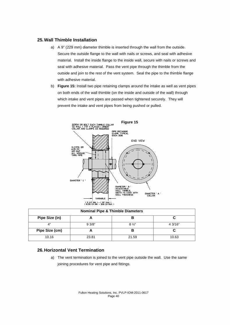
25. Wall Thimble Installation
a) A 9” (229 mm) diameter thimble is inserted through the wall from the outside.
Secure the outside flange to the wall with nails or screws, and seal with adhesive
material. Install the inside flange to the inside wall, secure with nails or screws and
seal with adhesive material. Pass the vent pipe through the thimble from the
outside and join to the rest of the vent system. Seal the pipe to the thimble flange
with adhesive material.
b) Figure 15: Install two pipe retaining clamps around the intake as well as vent pipes
on both ends of the wall thimble (on the inside and outside of the wall) through
which intake and vent pipes are passed when tightened securely. They will
prevent the intake and vent pipes from being pushed or pulled.
Nominal Pipe & Thimble Diameters
Pipe Size (in) A B C
4” 9 3/8” 8 ½” 4 3/16”
Pipe Size (cm) A B C
10.16 23.81 21.59 10.63
26. Horizontal Vent Termination
a) The vent termination is joined to the vent pipe outside the wall. Use the same
joining procedures for vent pipe and fittings.
Figure 15
Fulton Heating Solutions, Inc. PVLP-IOM-2011-0617
Page 41
b) The termination of the vent system must be at least 12” (305mm) above the
finished grade, or at least 12” (305mm) above normal snow accumulation level (for
applicable geographical regions).
c) Refer back to Figure 14: The termination of the vent system shall not be located in
traffic areas such as walk-ways, adjacent buildings, openable windows and building
openings unless the venting system is at least 7 feet (2.1m) above finished grade
(National Fuel Gas Code, ANSI Z223.1)
d) The vent termination must be at least 4 feet (1.22m) horizontally from, and in no
case above or below--unless a 4 foot (1.22m) horizontal distance is maintained
from-- electric meters, gas meters, regulators, and relief equipment.
e) The air supply inlet and exhaust outlet must be separated by a distance ranging
from 3ft. (0.91m) (minimum) to 10ft. (3.05m) (maximum) on the same wall. The
exhaust outlet must be installed a minimum of 2ft. (610mm) above and downwind
from air supply inlet to prevent exhaust recirculation. Under certain wind conditions
some building materials may be affected by flue products expelled in close
proximity to unprotected surfaces. Sealing or shielding of the exposed surfaces
with a corrosion resistant material (such as aluminum sheet) may be required to
prevent staining or deterioration.
f) Do not locate the vent termination too close to shrubbery as flue products may
stunt or kill them.
27. Installation Checkpoints
a) Before Starting The Boiler: Do not turn on the boiler unless it is filled with water to
the correct level (may be seen through gauge glass).
b) Check that the front door of the air decoupler is closed.
c) Check pressure setting.
d) Open the manual shutoff gas valve.
e) Close the circuit breaker or the fuse disconnect.
f) Turn the on-off switch to “ON”.
28. Testing Ignition Safety Shut Off
a) Open gas shut off valve, allowing gas to flow to boiler. Close gas shut off valve.
Reset low gas pressure switch. Turn on the boiler. The boiler will run through its
purge and trial for ignition cycle. After 6 seconds of ignition trial, the boiler will
recycle. Switch the boiler off. Open the gas shut off valve. Restart the boiler.
29. Measure Gas Flow Rate
Fulton Heating Solutions, Inc. PVLP-IOM-2011-0617
Page 42
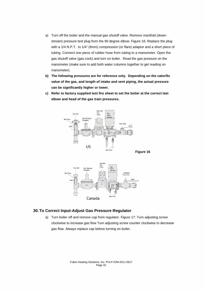
a) Turn off the boiler and the manual gas shutoff valve. Remove manifold (down-
stream) pressure test plug from the 90 degree elbow. Figure 16: Replace the plug
with a 1/4 N.P.T. to 1/4" (6mm) compression (or flare) adaptor and a short piece of
tubing. Connect one piece of rubber hose from tubing to a manometer. Open the
gas shutoff valve (gas cock) and turn on boiler. Read the gas pressure on the
manometer (make sure to add both water columns together to get reading on
manometer).
b) The following pressures are for reference only. Depending on the calorific
value of the gas, and length of intake and vent pip ing, the actual pressure
can be significantly higher or lower.
c) Refer to factory supplied test fire sheet to set the boiler at the correct last
elbow and head of the gas train pressures.
30. To Correct Input-Adjust Gas Pressure Regulator
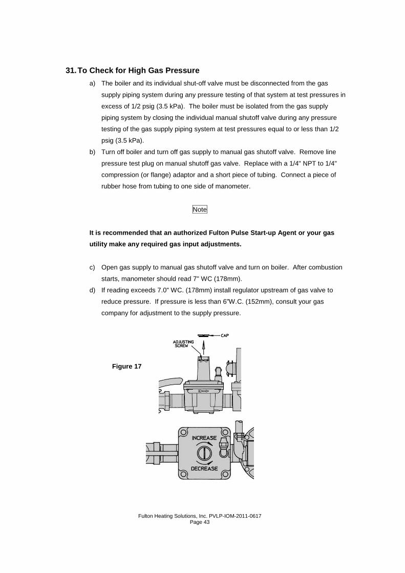
a) Turn boiler off and remove cap from regulator. Figure 17: Turn adjusting screw
clockwise to increase gas flow Turn adjusting screw counter clockwise to decrease
gas flow. Always replace cap before turning on boiler.
Figure 16
Fulton Heating Solutions, Inc. PVLP-IOM-2011-0617
Page 43
31. To Check for High Gas Pressure
a) The boiler and its individual shut-off valve must be disconnected from the gas
supply piping system during any pressure testing of that system at test pressures in
excess of 1/2 psig (3.5 kPa). The boiler must be isolated from the gas supply
piping system by closing the individual manual shutoff valve during any pressure
testing of the gas supply piping system at test pressures equal to or less than 1/2
psig (3.5 kPa).
b) Turn off boiler and turn off gas supply to manual gas shutoff valve. Remove line
pressure test plug on manual shutoff gas valve. Replace with a 1/4" NPT to 1/4"
compression (or flange) adaptor and a short piece of tubing. Connect a piece of
rubber hose from tubing to one side of manometer.
Note
It is recommended that an authorized Fulton Pulse S tart-up Agent or your gas
utility make any required gas input adjustments.
c) Open gas supply to manual gas shutoff valve and turn on boiler. After combustion
starts, manometer should read 7" WC (178mm).
d) If reading exceeds 7.0" WC. (178mm) install regulator upstream of gas valve to
reduce pressure. If pressure is less than 6”W.C. (152mm), consult your gas
company for adjustment to the supply pressure.
Figure 17
Fulton Heating Solutions, Inc. PVLP-IOM-2011-0617
Page 44
32. For High Gas Pressure Installations
a) In high gas pressure areas, it is good practice to step the pressure down as
described below.
1. Locate the stepdown regulator as far away from the pulse boiler as
possible.
2. When stepping down from more than 2 psig to 7" WC (14 kPa to
1.75 kPa), the stepdown should be done in two steps:
a. Reduce the pressure to 2 psig (14 kPa).
b. Reduce the pressure from 2 psig to 7" WC (14 kPa to 1.75
kPa).
3. The preferred regulator for this application is the Fisher S Series
with lock up capability with booster cartridge.
4. Consult your Authorized Fulton Representative for selection.
b) This recommendation is made to avoid the regulators chattering. It is also
recommended to avoid high lockup pressures which can cause light off
reliability problems.
c) Regulators, other than specified, may be acceptable, but it has been our
experience that the above listed regulators operate the best.
Note
After installation is complete and prior to operati on, the pressure vessel
should be cleaned.
33. Cleaning the Pressure Vessel
a) After the boiler has been installed and before it is placed in service, it is advisable
to purge the pressure vessel of any oil film, dirt, or other impurities. Clean the
pressure vessel as follows:
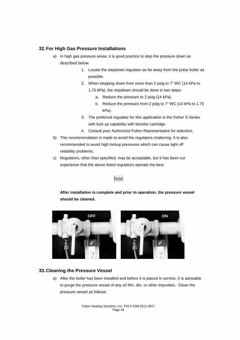
OFF ON
Fulton Heating Solutions, Inc. PVLP-IOM-2011-0617
Page 45
1. Isolate the boiler from the system by shutting off the main steam
valve.
2. Remove the steam safety valve.
3. Mix Oxiclean (commercially available fabric cleaner) with water in a
one-gallon container and pour it into the boiler through the steam
safety valve opening.
4. The mixture of Oxiclean to water is as follows:
Boiler Size Oxiclean
18-30 2 lb (908 g)
5. Replace the steam safety valve.
6. Fill the boiler with water. Water level is about center in the water
gauge glass.
7. Generate 5 PSI (0.352 kg/cm2) of steam and shut off the boiler.
Allow this hot solution to remain in the boiler for 10 minutes.
8. Drain and flush the boiler twice with fresh water.
9. To remove all the oil and dirt from the main steam and the
condensate return lines, allow the returns to go into a floor drain or
a safe discharge point for the first week of operation.
Note
An alternate method of boiling out the boiler can b e used. Mix the Oxiclean
solution and put the slurry into the feed tank dire ctly. Allow feedwater pumps
to pump the treated water into the boiler.
34. Before Leaving the Installation
a) Check all controls to insure they are operating properly. Cycle boiler several times
by raising and lowering operating pressure.
b) Make sure installation complies with all applicable codes.

Fulton Heating Solutions, Inc. PVLP-IOM-2011-0617
Page 46

Fulton Heating Solutions, Inc. PVLP-IOM-2011-0617
Page 47
Section 3

Fulton Heating Solutions, Inc. PVLP-IOM-2011-0617
Page 48
Fulton Heating Solutions, Inc. PVLP-IOM-2011-0617
Page 49
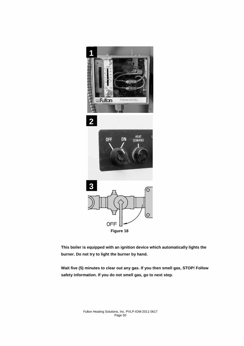
Section 3 – Operation 1. Instructions
a) Post these instructions in an appropriate place near the boiler and maintain in good
legible condition.
Warning
If you do not follow these instructions exactly, a fire or explosion may result
causing property damage, personal injury, or loss o f life.
b) Fulton low pressure steam pulse combustion boilers do not have a pilot. They are
equipped with an ignition device which automatically lights the boiler. Do not try to
light the boiler by hand. BEFORE OPERATING smell all around the boiler area for
gas. Be sure to smell next to the floor as some gas is heavier than air and will
settle. IF YOU SMELL GAS : Do not light any appliance. Do not touch any electric
switch. Do not use any phone in your building. Immediately call your gas supplier
from a neighbor’s phone, and then follow your gas supplier’s instructions. If you
cannot reach your gas supplier, call the fire department. Use only your hand to
turn the gas cock knob. Never use tools. If the knob will not turn by hand, don’t try
to repair it. Call a qualified service technician. FORCE OR ATTEMPTED REPAIR
MAY RESULT IN A FIRE OR EXPLOSION.
Note
DO NOT use this boiler if any part has been under w ater. Immediately call a
qualified service technician to inspect the boiler and to replace any part of
the control system and/or gas control(s) which has been under water.
c) Shut off the main manual supply valve when the equipment is closed down for an
extended period of time.
d) Before operating your Fulton Pulse Combustion Lo w Pressure Heating
Boiler: STOP! Make sure you have read and followed all previous safety
information.
1. Set the pressure control to lowest setting.
2. Turn off all electric power to the boiler.
3. Turn gas cock knob clockwise to “OFF”.
Figure 18. (This gas cock knob is also the emergency shut-off
device.)
Fulton Heating Solutions, Inc. PVLP-IOM-2011-0617
Page 50
This boiler is equipped with an ignition device whi ch automatically lights the
burner. Do not try to light the burner by hand.
Wait five (5) minutes to clear out any gas. If you then smell gas, STOP! Follow
safety information. If you do not smell gas, go to next step.
Figure 18
1
2
3
Fulton Heating Solutions, Inc. PVLP-IOM-2011-0617
Page 51
2. Start-Up Preparation
a) Check with local authorities where approval for start-up is required. In some
localities, final inspection of services may be required.
b) Refer to the following instructions on the initial start-up of the pulse boiler and on
every subsequent occasion when restarting boiler after shut down:
1. Open the steam stop valve at the top of the boiler.
2. Open all valves in the water feed line.
3. Open the water column isolation valves.
4. Open the water gauge valves.
5. Close the blow down valves on the boiler and on the water column.
6. Switch on the feedwater pump motor.
Note
The pump will continue to operate until the water r eaches the correct level in
the boiler. This level is approximately the center of the water gauge.
3. Starting the Fulton Pulse Combustion Boiler
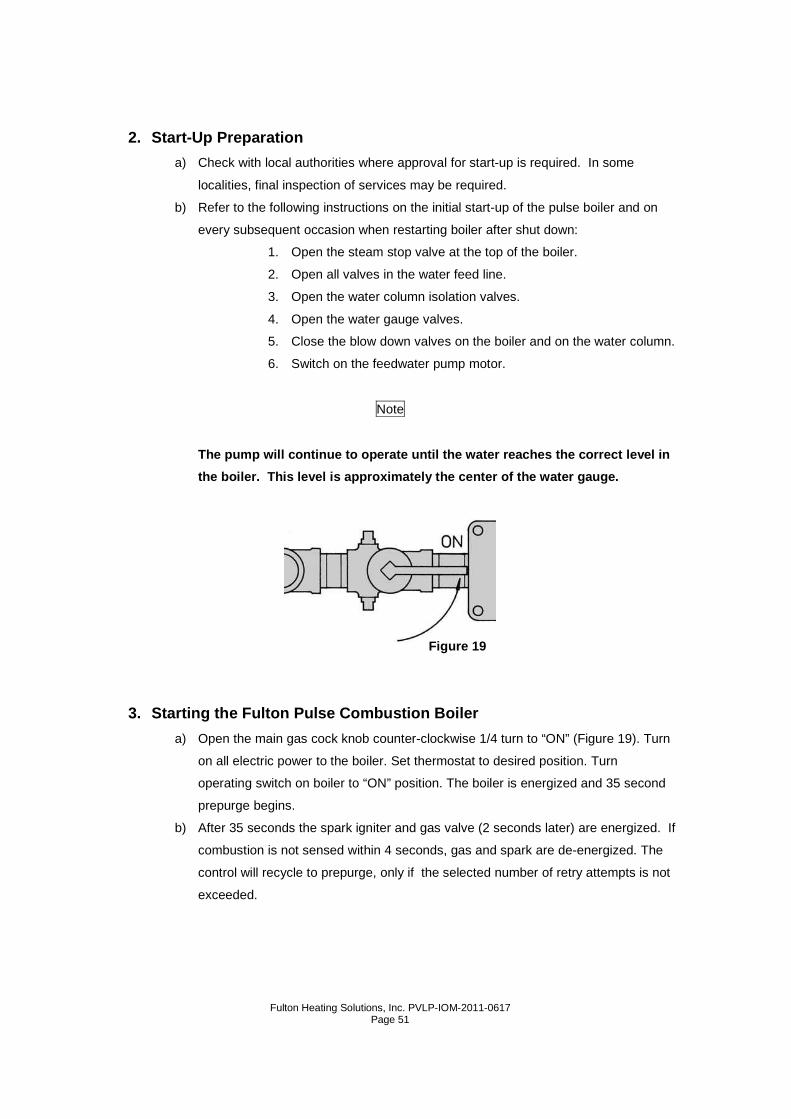
a) Open the main gas cock knob counter-clockwise 1/4 turn to “ON” (Figure 19). Turn
on all electric power to the boiler. Set thermostat to desired position. Turn
operating switch on boiler to “ON” position. The boiler is energized and 35 second
prepurge begins.
b) After 35 seconds the spark igniter and gas valve (2 seconds later) are energized. If
combustion is not sensed within 4 seconds, gas and spark are de-energized. The
control will recycle to prepurge, only if the selected number of retry attempts is not
exceeded.
Figure 19
Fulton Heating Solutions, Inc. PVLP-IOM-2011-0617
Page 52
c) If after 37 seconds the gas valve opens but the boiler does not start, check the
spark plug to be sure it is working properly.
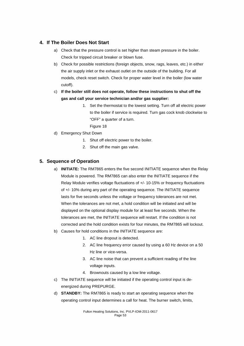
d) The plug may be bad or the plug wire may be loose. Check gap of plug It should be
.050" to .060". When replacing plug be sure to use anti-seize compound on threads
of plug. When the unit fires and flame is sensed in the combustion chamber, the
unit will continue to operate until main power is shut off to the controller either
through the temperature switch or main power switch. Once the flame is sensed
the blower and spark will turn off.
Caution
Should overheating occur or the gas supply fail to shut off, do not turn off or
disconnect the electrical supply to the pump. Inst ead, shut off the gas
supply at a location external to the boiler.
.050” - .060”
Fulton Heating Solutions, Inc. PVLP-IOM-2011-0617
Page 53
4. If The Boiler Does Not Start
a) Check that the pressure control is set higher than steam pressure in the boiler.
Check for tripped circuit breaker or blown fuse.
b) Check for possible restrictions (foreign objects, snow, rags, leaves, etc.) in either
the air supply inlet or the exhaust outlet on the outside of the building. For all
models, check reset switch. Check for proper water level in the boiler (low water
cutoff).
c) If the boiler still does not operate, follow these instructions to shut off the
gas and call your service technician and/or gas sup plier:
1. Set the thermostat to the lowest setting. Turn off all electric power
to the boiler if service is required. Turn gas cock knob clockwise to
“OFF” a quarter of a turn.
Figure 18
d) Emergency Shut Down
1. Shut off electric power to the boiler.
2. Shut off the main gas valve.
5. Sequence of Operation
a) INITIATE: The RM7865 enters the five second INITIATE sequence when the Relay
Module is powered. The RM7865 can also enter the INITIATE sequence if the
Relay Module verifies voltage fluctuations of +/- 10-15% or frequency fluctuations
of +/- 10% during any part of the operating sequence. The INITIATE sequence
lasts for five seconds unless the voltage or frequency tolerances are not met.
When the tolerances are not met, a hold condition will be initiated and will be
displayed on the optional display module for at least five seconds. When the
tolerances are met, the INITIATE sequence will restart. If the condition is not
corrected and the hold condition exists for four minutes, the RM7865 will lockout.
b) Causes for hold conditions in the INITIATE sequence are:
1. AC line dropout is detected.
2. AC line frequency error caused by using a 60 Hz device on a 50
Hz line or vice-versa.
3. AC line noise that can prevent a sufficient reading of the line
voltage inputs.
4. Brownouts caused by a low line voltage.
c) The INITIATE sequence will be initiated if the operating control input is de-
energized during PREPURGE.
d) STANDBY: The RM7865 is ready to start an operating sequence when the
operating control input determines a call for heat. The burner switch, limits,
Fulton Heating Solutions, Inc. PVLP-IOM-2011-0617
Page 54
operating control, inter-locks, critical loads and all microcomputer monitored circuits
must be in the correct state for the RM7865 to continue into the PREPURGE
sequence.
e) NORMAL START-UP PREPURGE: The RM7865 provides a PREPURGE timing of
35 seconds with power applied and the RM7865 operating control indicating a call
for heat.
1. Combustion pressure switch, purge fan switch ILK, burner switch,
limits, operating control and all microcomputer
monitored circuits must be in the correct operating state.
2. The fan motor output, terminal 5, is powered to start the
PREPURGE sequence.
3. The purge fan switch ILK input must close within three seconds to
start the 35 second PRE-PURGE; otherwise, lockout occurs.
f) IGNITION TRIALS:
1. Combustion Pressure Establishing Period (CPEP):
a. The ignition transformer, terminal 10, is energized
two seconds prior to opening of the main fuel
valve.
b. The Main fuel valve, terminal 8 is energized for
four seconds. Combustion pressure must be
proven by the end of the six seconds of CPEP to
allow the sequence to continue to the combustion
pressure Stabilization Period. If combustion
pressure is not proven by the end of CPEP, the
RM7865 will recycle to PREPURGE.
2. Combustion Pressure Stabilization Period (CPSP):
a. If the Combustion Pressure Switch is energized at
the end of CPEP, the RM7865 enters an eight
second Combustion Pressure Stabilization Period.
If the Combustion Pressure Switch ILK opens, the
RM7865 will recycle to PREPURGE if the selected
number of retry attempts is not exceeded. After
the eight seconds, the RM7865 will enter the RUN
period.
g) RUN
1. After the CPSP/MFSP, the RM7865 will enter into the RUN
sequence. The RM7865 will remain in RUN until the controller
input, terminal 6, opens indicating that the demand is satisfied or
Fulton Heating Solutions, Inc. PVLP-IOM-2011-0617
Page 55
that the limit has opened. If the Combustion Pressure Switch
Interlock opens or the flame signal is lost (RM7865B), the RM7865
will enter the POSTPURGE period. The fan motor is de-energized
during RUN.
h) POSTPURGE
1. The RM7865 provides a 35 seconds POSTPURGE following the
completion of the RUN period; and the fan motor output is powered
to drive all products of combustion and any unburned fuel from the
combustion chamber. The RM7865 will also enter POSTPURGE if
the operating control input is de-energized during CPEP, CPSP or
RUN.
a. The main fuel valve and ignition, terminals 8 and
10, are de-energized. The purge fan switch is
energized and the POSTPURGE period begins.
b. After the 35 second POSTPURGE period is
completed, the RM7865 returns to STANDBY.
6. Sequence of Operation for Modulated Pulse Steam Boilers
a) When the boiler receives a call for heat, the prepurge cycle is initiated.
b) The mod motor is driven to high fire.
c) After the high fire switch in the mod motor is closed, the prepurge count
begins.
d) Following prepurge, the spark generator energizes and the gas valves open.
e) Upon proof of flame, the fan and spark are turned off.
f) At this point, the modulation pressure controller controls the mod motor and
firing rate of the boiler.
g) When the boiler outlet pressure reaches set point, the boiler is turned off and
prepurge begins.
h) The boiler control then monitors the boiler pressure and waits for the next call
for heat.
Note
A series of relays are used in the above sequence o f operation. Please refer
to the wiring diagram for details.
7. Programming Instructions for Yokogawa UT320 Stan dard Program
a) Hold SET/ENT key until control is in Operator mode. PV display will show oppa.
Fulton Heating Solutions, Inc. PVLP-IOM-2011-0617
Page 56
b) Press Down Arrow key until control is in Set Up mode. PV display will show stup.
c) Press SET/ENT key twice until control is in Function mode. PV display will show
func.
d) Press Down Arrow key until control is in Input/Output mode. PV display will show
I/o.
e) Press SET/ENT key to bring you to the first parameter in the Input/Output mode.
f) Parameter Setting Procedure: The values for each parameter that are shown in
the PV display should match the values entered at the factory. If they differ, press
the Up Arrow key or Down Arrow key until the factory value is displayed. Some
values, such as High Pressure Range (rh) , can be adjusted according to system
design. Once the desired value is displayed, press the SET/ENT key to maintain it
in the control’s memory.
g) Only those values that are Shaded with Bold & Italic values in the menu pertain
to the program constructed for Fulton pulse boilers.
Note
It is important to know that if the following param eters are altered, the entire
set of factory values will be altered: (In) or (UNI T) located in the Input/Output
Menu; (AL1) in the Functional Parameters Menu; (A1) in the Operating
Parameters Menu.
h) After the Input/Output values have been confirmed or entered, return to Function
mode by holding the SET/ENT key until the PV display shows func.
i) Repeat Parameter Setting Procedure.
j) The HY1 parameter or Hysteresis may be adjusted to overshoot the setpoint
temperature by half the value of A1 entered. The unit will also start again only after
the supply temperature decreases half the value entered below setpoint.
k) After the Function values have been confirmed or entered, hold the SET/ENT key
until the Setpoint Temperature appears in the PV Display.
l) Repeat the last step until the control is in Operator mode. The PV Display will show
oppa. Repeat Parameter Setting Procedure.
m) When the PID parameter appears in the PV Display, press one of the Arrow keys
until (1) appears in the SP Display, press SET/ENT--this will take you to a subset
of parameters. Repeat Parameter Setting Procedure.
n) After confirming or entering the PID value (1.MR), the control automatically
returns to the remaining Operating parameters. Repeat Parameter Setting
Procedure.
Fulton Heating Solutions, Inc. PVLP-IOM-2011-0617
Page 57
o) When finished, hold SET/ENT key to return to Setpoint Temperature. Boiler is
ready for operation.
Note
If the rh (Range High) value has been changed in th e Input/Output Menu, the
Setpoint pressure will read zero (0) after return f rom the menus. Simply press
the Up Arrow key until the desired setpoint value i s shown. Hit SET/ENT once
to store and begin operation.
8. Worksheets
a) Use the worksheets to record the values set at site under Customer Value . If the
unit is not operating correctly, call your Fulton representative. Have your customer
values handy for trouble shooting.
9. Advanced Programming Features
a) The Yokogawa UT320 is a sophisticated temperature control with “smart” features
that internally calculates how close the appliance is to setpoint and adjusts it
proportionally to arrive without overshooting. The smart logic must be initiated in
the Operating parameters by setting the following values:
1. Under the Functional Parameters menu, scroll to HY1 and set the
value to 20.
2. When the process temperature is within 10oF of the setpoint
temperature, scroll to AT in the Operating Parameters menu
and set the value to 1.
3. AT or Auto-Tune will increase the modulation (mod) motor output
to 100% until the process temperature is 2% of input span above
setpoint. The output will go to 0% until the process temperature
decreases to 2% of input span below setpoint.
4. The control will increase the mod motor again to 100% until the
process temperature is 2% of input span above setpoint. During
this time the manual mode light on the temperature control will
be flashing until completed.
5. If the three samples are not the same, an error message will be
displayed and the temperature will drop out of Auto-Tune mode.
Reset the zero and span adjustments on the mod motor and/or
adjust modulation linkage accordingly.

Fulton Heating Solutions, Inc. PVLP-IOM-2011-0617
Page 58
6. PID values will be set when this procedure is successfully
completed.
7. Repeat Step 1 and change the HY1 value back to 10 (standard).
8. Return to Auto mode.
Fulton Heating Solutions, Inc. PVLP-IOM-2011-0617
Page 59
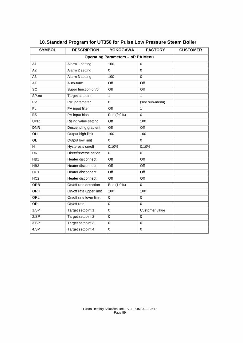
10. Standard Program for UT350 for Pulse Low Pressu re Steam Boiler
SYMBOL DESCRIPTION YOKOGAWA FACTORY CUSTOMER
Operating Parameters – oP.PA Menu
A1 Alarm 1 setting 100 0
A2 Alarm 2 setting 0 0
A3 Alarm 3 setting 100 0
AT Auto-tune Off Off
SC Super function on/off Off Off
SP.no Target setpoint 1 1
Pld PID parameter 0 (see sub-menu)
FL PV input filter Off 1
BS PV input bias Eus (0.0%) 0
UPR Rising value setting Off 100
DNR Descending gradient Off Off
OH Output high limit 100 100
OL Output low limit 0 0
H Hysteresis on/off 0.10% 0.10%
DR Direct/reverse action 0 0
HB1 Heater disconnect Off Off
HB2 Heater disconnect Off Off
HC1 Heater disconnect Off Off
HC2 Heater disconnect Off Off
ORB On/off rate detection Eus (1.0%) 0
ORH On/off rate upper limit 100 100
ORL On/off rate lover limit 0 0
OR On/off rate 0 0
1.SP Target setpoint 1 0 Customer value
2.SP Target setpoint 2 0 0
3.SP Target setpoint 3 0 0
4.SP Target setpoint 4 0 0
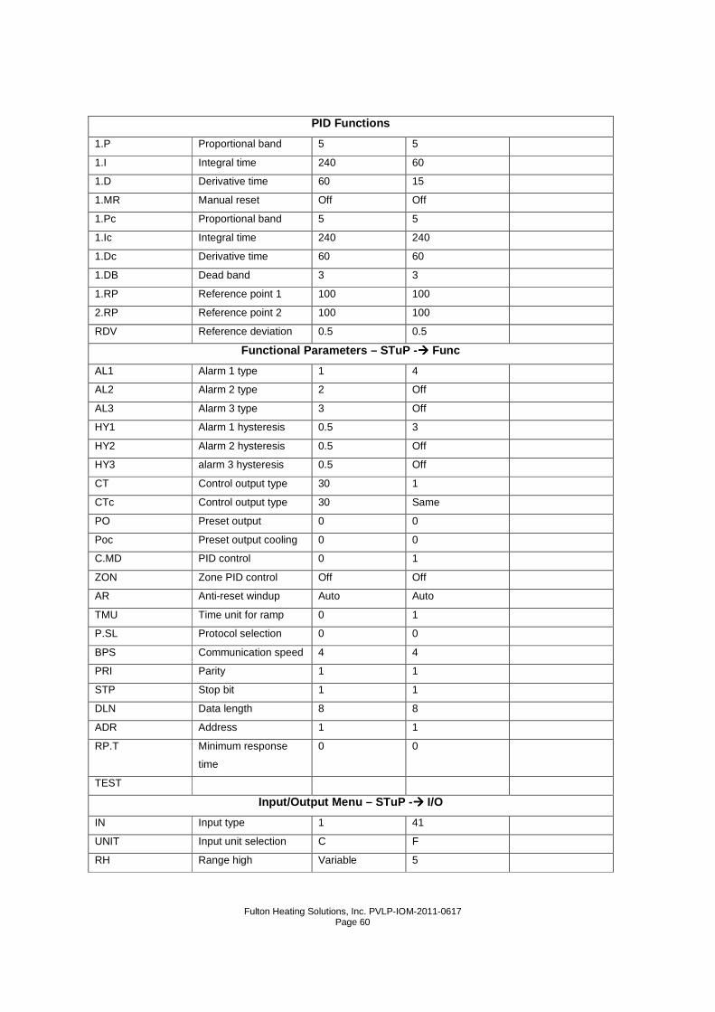
Fulton Heating Solutions, Inc. PVLP-IOM-2011-0617
Page 60
PID Functions
1.P Proportional band 5 5
1.I Integral time 240 60
1.D Derivative time 60 15
1.MR Manual reset Off Off
1.Pc Proportional band 5 5
1.Ic Integral time 240 240
1.Dc Derivative time 60 60
1.DB Dead band 3 3
1.RP Reference point 1 100 100
2.RP Reference point 2 100 100
RDV Reference deviation 0.5 0.5
Functional Parameters – STuP -���� Func
AL1 Alarm 1 type 1 4
AL2 Alarm 2 type 2 Off
AL3 Alarm 3 type 3 Off
HY1 Alarm 1 hysteresis 0.5 3
HY2 Alarm 2 hysteresis 0.5 Off
HY3 alarm 3 hysteresis 0.5 Off
CT Control output type 30 1
CTc Control output type 30 Same
PO Preset output 0 0
Poc Preset output cooling 0 0
C.MD PID control 0 1
ZON Zone PID control Off Off
AR Anti-reset windup Auto Auto
TMU Time unit for ramp 0 1
P.SL Protocol selection 0 0
BPS Communication speed 4 4
PRI Parity 1 1
STP Stop bit 1 1
DLN Data length 8 8
ADR Address 1 1
RP.T Minimum response
time
0 0
TEST
Input/Output Menu – STuP -���� I/O
IN Input type 1 41
UNIT Input unit selection C F
RH Range high Variable 5
Fulton Heating Solutions, Inc. PVLP-IOM-2011-0617
Page 61
RL Range low Variable 1
SDP Scale decimal point 1 0
SH Scale high 100 30 or variable
SL Scale low 0 0
RJC On/off On On
BSL Burnerout selection 1 1
OT Output type 0 2
RET Retransmission 1 1
RTH Retransmission high Variable Variable
RTL Retransmission low Variable 0
DIS Digital input Off 1
C.S1 Custom select Off Off
C.S2 Custom select Off Off
C.S3 Custom select Off Off
C.S4 Custom select Off Off
LOCK Key lock Off Off
PWD password 0 0
11. Linkage Adjustment for Pulse Modulated Boilers
a) This instruction covers the adjustment of the linkage arms and rods between the
modulation (mod) motor and gas butterfly valve and also between the mod motor
and exhaust butterfly valve.
12. Prior to Start-Up
a) With the boiler off, both the gas and exhaust butterfly valves will be in the closed
position.
13. Setting High Fire
a) When the boiler is energized the mod motor will be driven to High Fire driving the
gas and exhaust butterfly valves to the open position.
b) At High Fire the slot in the shaft of the mod motor should be horizontal in
orientation.
c) At this point it is important to note that the mod motor and gas butterfly valve
linkage arms are as close to parallel as possible. Also note that the mod motor and
exhaust butterfly valve linkage arms should be parallel.
d) Location of the lock nuts on the linkage rods is not important.
Fulton Heating Solutions, Inc. PVLP-IOM-2011-0617
Page 62
14. Linkage Relationships
a) The location of the linkage rods and the speed at which the butterfly gas valve and
butterfly exhaust valve opens or closes will determine whether the unit operates
smoothly or not.
15. Gas Butterfly Valve
a) The longer the radius on the mod motor pivot arm, the quicker the gas butterfly
valve closes. Conversely, the shorter the radius the slower the gas butterfly valve
closes.
b) The longer the radius on the gas valve pivot arm, the slower the gas butterfly valve
closes. Conversely, the shorter the radius the quicker the gas butterfly valve
closes.
16. Exhaust Butterfly Valve
a) The longer the radius on the mod motor pivot arm, the quicker the exhaust butterfly
valve closes. Conversely, the shorter the radius the slower the exhaust butterfly
valve closes.
b) The longer the radius on the exhaust valve pivot arm, the slower the exhaust
butterfly valve closes. Conversely, the shorter the radius the quicker the exhaust
butterfly valve closes.
c) At High Fire the linkage arms should NOT begin or finish travel in the vertical
position. If this occurs there is a possibility that the gears will bind and cause
damage to the mod motor.
d) The gas pressure regulator is the only means for adjusting High Fire input to the
factory test fire values.
e) After the boiler is operated at High Fire to the desired settings, proceed to operate
at Low Fire.
17. Low Fire Settings
a) Manually adjust the temperature controller on the front of the boiler to read 50%
input. At 50% check to see if the unit is within test fire values. Proceed to step the
boiler down to 40%, 30%, 20% 10% and 0% each time checking to see if the unit is
within test fire values. 0% represents low fire and 100% represents high fire.
b) If you are unable to reach 0%, you will need to make adjustments on the gas valve
to either increase or decrease fuel input. The exhaust butterfly valve may also
need adjustment. Start by adjusting one valve at a time.
Fulton Heating Solutions, Inc. PVLP-IOM-2011-0617
Page 63
c) The gas butterfly valve should be used to adjust Low Fire input. The exhaust
butterfly valve should be adjusted to set proper combustion. Closing the exhaust
butterfly valve will also decrease input slightly.
d) At Low Fire the linkage arms should NOT begin or finish travel in the vertical
position. If this occurs there is a possibility that the gears will bind and cause
damage to the mod motor.
18. Procedure to Zero and Span the Modulation Motor
a) The following procedure is done on each modulation (mod) motor at the factory. It
may be necessary to do in the field in the event the mod motor requires
replacement or the mod motor linkage is moving up or down the range when there
is no change in the operating or setpoint temperature difference.
1. Turn boiler OFF.
2. Put the temperature control in manual mode (press the A/M key
once – the SP display will show a value between 0 and 100).
3. Follow the electrical drawing and remove the connection between
(F) and (-) on the mod motor. Disconnect relay CR3
for safety.
4. Contact point 16(+) on the temperature control is wired through
CR1 normally closed to contact point (+) on the mod motor.
Contact point 17(-) on the temperature control must be
disconnected. Install a jumper from 17(-) to contact point (-) on
the mod motor. This will provide a direct connection between (+)
and (-) on the temperature control to (+) and (-) on the mod motor.
5. Refer to the zero and span adjustment information for the mod
motor (Pages 5 and 10). Follow steps 1 through 8 on page 10 of
the mod motor brochure included in the Pulse Operation and
Maintenance manual.
6. Be sure the linkage does not bend or catch in any position during
travel.
7. When zero and span are complete, scroll the input rate to 100% -
this will drive the burner to high fire and purge any left over
combustibles- and adjust the blue cam, if necessary, until the high
edge of the cam pushes against the end switch.
8. Remove the jumper and install the wire on contact point 17(+) of
the temperature control. Connect relay CR3.
9. Test the mod motor signal by manually setting the output signal
from zero (low fire – 4 mA) to 100 (high fire – 20 mA). At high fire,
Fulton Heating Solutions, Inc. PVLP-IOM-2011-0617
Page 64
the slot in the shaft of the mod motor should be horizontal in
orientation.
Note
The unit will still shut off at setpoint plus HY1 ( standard settings). Also, being
in manual mode, the temperature control ignores any PID or auto tune
settings.
10. Set the temperature back to the Auto setting by pressing the A/M
key – the operating and setpoint temperatures will be displayed in
the PV and SP displays, respectively.

Fulton Heating Solutions, Inc. PVLP-IOM-2011-0617
Page 65
Section 4

Fulton Heating Solutions, Inc. PVLP-IOM-2011-0617
Page 66
Fulton Heating Solutions, Inc. PVLP-IOM-2011-0617
Page 67
Section 4 – Maintenance Note
Your Fulton Pulse Combustion Low Pressure Steam Boi ler has been
designed for years of trouble-free performance. To ensure the continued
safety and efficiency of the boiler, the schedule o f maintenance outlined in
this section should be adhered to. The boiler shoul d be inspected annually.
All service should be performed by a certified cont ractor.
1. Before Each Heating Season
a) Check air intake and exhaust vent outlet for any blockage or restrictions.
b) Check the air intake and exhaust vent piping for sagging.
c) Check the water level in the sight glass (water level should be about halfway in the
sight glass) to prevent dry fire condition.
Warning
Keep boiler area clear and free from combustible ma terials, gasoline and
other flammable vapors and liquids.
For Typical heating applications (closed loop syste m) feedwater treatment
may not be necessary.
2. Recommended Weekly Maintenance
a) Make inspection of boiler and system for leaks or any unusual condition in the
operation of the controls and feed pump.
b) To assure safe operation, the boiler power should be left on during daily blow down
so that correct operation of the low water relay may be checked. While blowing
down boiler, the pressure will drop significantly. While blowing down with power on,
it is normal to hear boiler feed pump come on.
c) Combustion should not occur. If combustion does occur, turn boiler off and contact
your local service representative or our factory immediately.
d) Blow down weekly by starting the boiler and generating not more than 3 PSI
(.25KG/CM2) of steam. Then shut off the boiler. Turn on tap water to blow-off
separator. Open the boiler blow off valve for approximately 10 seconds. Close the
valve. Shut off tap water to blow-off separator. Blow down water level control each
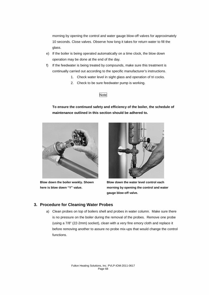
Fulton Heating Solutions, Inc. PVLP-IOM-2011-0617
Page 68
morning by opening the control and water gauge blow-off valves for approximately
10 seconds. Close valves. Observe how long it takes for return water to fill the
glass.
e) If the boiler is being operated automatically on a time clock, the blow down
operation may be done at the end of the day.
f) If the feedwater is being treated by compounds, make sure this treatment is
continually carried out according to the specific manufacturer’s instructions.
1. Check water level in sight glass and operation of tri cocks.
2. Check to be sure feedwater pump is working.
Note
To ensure the continued safety and efficiency of th e boiler, the schedule of
maintenance outlined in this section should be adhe red to.
Blow down the boiler weekly. Shown Blow down the water level control each
here is blow down “Y” value. morning by op ening the control and water
gauge blow-off valve.
3. Procedure for Cleaning Water Probes
a) Clean probes on top of boilers shell and probes in water column. Make sure there
is no pressure on the boiler during the removal of the probes. Remove one probe
(using a 7/8” (22-2mm) socket), clean with a very fine emory cloth and replace it
before removing another to assure no probe mix-ups that would change the control
functions.

Fulton Heating Solutions, Inc. PVLP-IOM-2011-0617
Page 69
b) For replacement purposes, installed probe lengths are indicated in the chart below.
For a universally adaptable plug and probe which can be cut to length in the field to
fit all boilers, order Part No. 2-20-017.
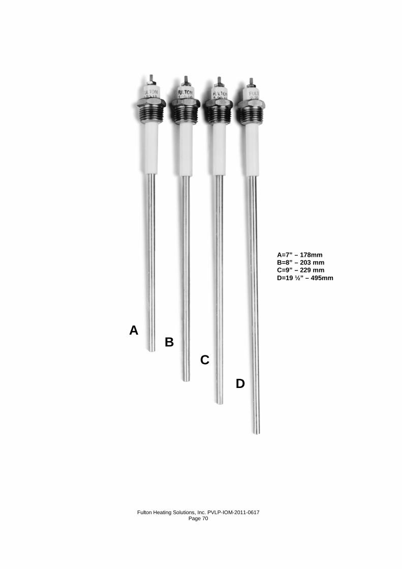
Fulton Heating Solutions, Inc. PVLP-IOM-2011-0617
Page 70
A=7” – 178mm B=8” – 203 mm C=9” – 229 mm D=19 ½” – 495mm
A B
C
D
Fulton Heating Solutions, Inc. PVLP-IOM-2011-0617
Page 71
4. Recommended Monthly Maintenance
a) Check that the low water cut-off relay is operating correctly in the following manner:
With the boiler operating, open the boiler blow down valve. When the water drops
below the required level (note the level in the water gauge glass) the pulse boiler
should shut off. This is when the water level falls below the float in the water level
control assembly and/or the boiler shell.
5. Recommended Quarterly Maintenance
a) With the boiler under no more than 10 PSI (70 kPa) pressure, check that the steam
safety valve is operating by lifting the lever. Shut off the boiler completely and
drain.
b) Remove the handholes and inspect the interior of the vessel for scale or sludge
deposits. The amount of deposits will indicate the efficiency of the water treatment
being used. The frequency of this inspection will be dependent on the condition of
the water side boiler.
c) Inspect the air intake and exhaust vent pipes for cracked or broken seals at the
joints.
d) Inspect the screens on the air intake and exhaust vent terminal and make sure they
are free of dirt or any foreign matter which may block terminals.
e) Blow down the boiler and the water level control completely as described
recommended daily maintenance.
f) Clean the water gauge glass. If any leakage is evident replace the gaskets. Always
replace the high impact plastic gauge glass protector which is standard on all
Fulton Boilers.
g) Clean water pump strainers.
6. Recommended Six Month Maintenance
a) With the boiler off and no pressure in the boiler, drain the water from the boiler
below the sight glass level.
b) Remove the float from the water level control by removing the bolts from the flange.
Clean any dirt or sediment from the bowl and glass.
c) Remove the sight glass. Inspect the glass for any chips, steam cuts or cracks.
Replace the glass if found.
d) Always install new gaskets on the sight glass.
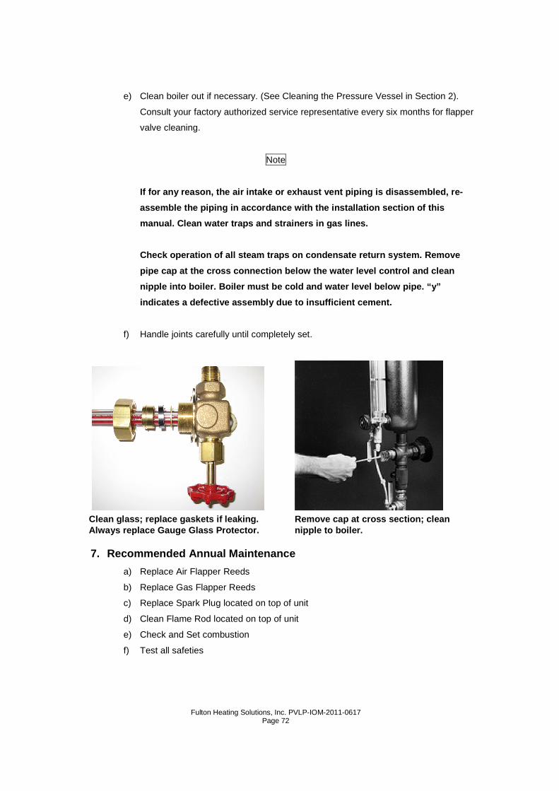
Fulton Heating Solutions, Inc. PVLP-IOM-2011-0617
Page 72
e) Clean boiler out if necessary. (See Cleaning the Pressure Vessel in Section 2).
Consult your factory authorized service representative every six months for flapper
valve cleaning.
Note
If for any reason, the air intake or exhaust vent p iping is disassembled, re-
assemble the piping in accordance with the installa tion section of this
manual. Clean water traps and strainers in gas line s.
Check operation of all steam traps on condensate re turn system. Remove
pipe cap at the cross connection below the water le vel control and clean
nipple into boiler. Boiler must be cold and water l evel below pipe. “y”
indicates a defective assembly due to insufficient cement.
f) Handle joints carefully until completely set.
7. Recommended Annual Maintenance
a) Replace Air Flapper Reeds
b) Replace Gas Flapper Reeds
c) Replace Spark Plug located on top of unit
d) Clean Flame Rod located on top of unit
e) Check and Set combustion
f) Test all safeties
Remove cap at cross section; clean nipple to boiler.
Clean glass; replace gaskets if leaking. Always replace Gauge Glass Protector.
Fulton Heating Solutions, Inc. PVLP-IOM-2011-0617
Page 73
8. Troubleshooting
The following troubleshooting guide will assist in the diagnosis and correction of minor field
problems. It should be used in conjunction with the unit wiring diagram. In any case
requiring additional assistance, the Fulton Service Department should be contacted.
Fault Code Diagnosis
Fault Code System Failure Recommended Troubleshooting
Fault 02
*AC Frequen/Noise*
Excess noise or device
running on slow AC
1. Check the relay module and display
module connections.
2. Reset and sequence the 7800.
3. Check the 7800 power supply to assure
that both frequency and voltage meet
specifications.
4. Check the backup power supply as
appropriate.
Fault 03
AC Line Dropout AC line dropout detected
1. Check the relay module and display
module connections.
2. Reset and sequence the 7800.
3.Check the 7800 power supply to assure that
both Frequency and voltage meet
specifications.
4. Check the backup power supply as
appropriate.
Fault 04
AC Frequency Device running on fast AC
1. Check the relay module and display
module connections.
2. Reset and sequence the 7800.
3.Check the 7800 power supply to assure that
both Frequency and voltage meet
specifications.
4. Check the backup power supply as
appropriate.
Fault 05
Low Line Voltage Low AC line detected
1. Check the relay module and display
module connections.
2. Reset and sequence the 7800.
3.Check the 7800 power supply to assure that
both Frequency and voltage meet
specifications.
4. Check the backup power supply as
appropriate.
Fault 32
Airflow Switch
Combustion airflow interlock
fault
1.Check wiring—correct any errors
2.inspect the fan, assure that there is no
Fulton Heating Solutions, Inc. PVLP-IOM-2011-0617
Page 74
blockage of the air intake and that it is
supplying air.
3.Assure that the airflow interlock switches
are functioning properly and that their
contacts are free from contaminants.
4.Reset and sequence the 7800 to prepurge.
Measure the voltage between terminal 7 and
G (ground). 120Vac should be present.
Fault 47
Jumpers Changed
The configuration jumpers
differ from the sample taken at
startup.
1.Inspect the jumper connections. Assure that
clipped jumpers have been completely
removed.
2.Reset and sequence the 7800.
3.If fault persists, replace the relay module.
Fault 54
Comb. Pressure
Combustion pressure switch
fault
1.Check wiring; correct any errors.
2.Inspect the combustion pressure switch to
assure that it is functioning properly.
3.Reset and sequence the 7865. During
standby or prepurge, measure the voltage
between terminal 20 and G (ground). 120
Vac should be present. If not, the combustion
pressure switch may be defective and need
replacement.
4.If fault persists, replace the relay module.
Fault 55
Purge Fan Sw. On
Purge fan switch is on when it
should be off
1.Check wiring; correct any errors.
2.Inspect the purge fan switch terminal 18
and connections. Assure that the switch is
functioning correctly and is not jumpered or
welded.
3.Reset and sequence the 7865.
4.If fault persists, replace the relay module.
Fault 57
Purge Fan Sw. Off
Purge fan switch is off when it
should be on
1.Inspect the purge fan switch terminal 18
and connections. Assure that the switch is
functioning correctly.
2.Reset and sequence the 7865.
3.If the fault persists, replace the relay
module.
Faults 105-127 Call Service 1.Replace 7865 controller.
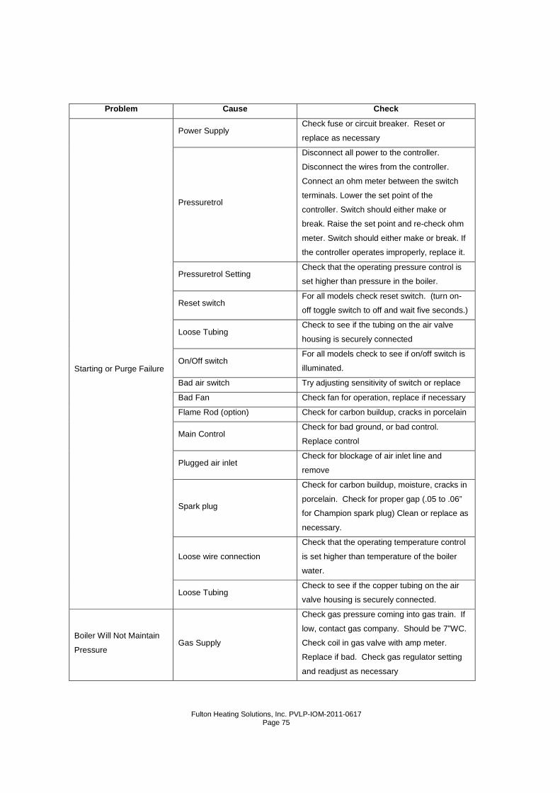
Fulton Heating Solutions, Inc. PVLP-IOM-2011-0617
Page 75
Problem Cause Check
Starting or Purge Failure
Power Supply Check fuse or circuit breaker. Reset or
replace as necessary
Pressuretrol
Disconnect all power to the controller.
Disconnect the wires from the controller.
Connect an ohm meter between the switch
terminals. Lower the set point of the
controller. Switch should either make or
break. Raise the set point and re-check ohm
meter. Switch should either make or break. If
the controller operates improperly, replace it.
Pressuretrol Setting Check that the operating pressure control is
set higher than pressure in the boiler.
Reset switch For all models check reset switch. (turn on-
off toggle switch to off and wait five seconds.)
Loose Tubing Check to see if the tubing on the air valve
housing is securely connected
On/Off switch For all models check to see if on/off switch is
illuminated.
Bad air switch Try adjusting sensitivity of switch or replace
Bad Fan Check fan for operation, replace if necessary
Flame Rod (option) Check for carbon buildup, cracks in porcelain
Main Control Check for bad ground, or bad control.
Replace control
Plugged air inlet Check for blockage of air inlet line and
remove
Spark plug
Check for carbon buildup, moisture, cracks in
porcelain. Check for proper gap (.05 to .06”
for Champion spark plug) Clean or replace as
necessary.
Loose wire connection
Check that the operating temperature control
is set higher than temperature of the boiler
water.
Loose Tubing Check to see if the copper tubing on the air
valve housing is securely connected.
Boiler Will Not Maintain
Pressure Gas Supply
Check gas pressure coming into gas train. If
low, contact gas company. Should be 7”WC.
Check coil in gas valve with amp meter.
Replace if bad. Check gas regulator setting
and readjust as necessary
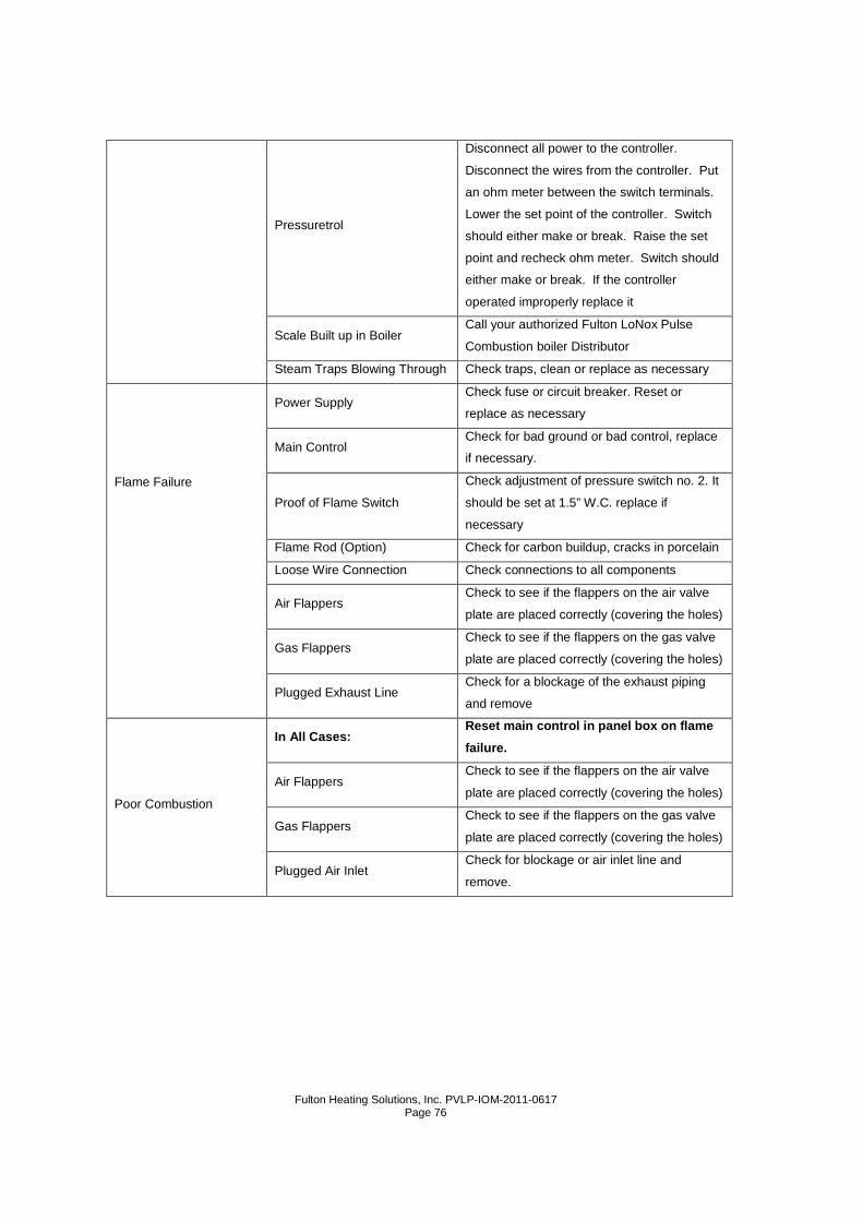
Fulton Heating Solutions, Inc. PVLP-IOM-2011-0617
Page 76
Pressuretrol
Disconnect all power to the controller.
Disconnect the wires from the controller. Put
an ohm meter between the switch terminals.
Lower the set point of the controller. Switch
should either make or break. Raise the set
point and recheck ohm meter. Switch should
either make or break. If the controller
operated improperly replace it
Scale Built up in Boiler Call your authorized Fulton LoNox Pulse
Combustion boiler Distributor
Steam Traps Blowing Through Check traps, clean or replace as necessary
Flame Failure
Power Supply Check fuse or circuit breaker. Reset or
replace as necessary
Main Control Check for bad ground or bad control, replace
if necessary.
Proof of Flame Switch
Check adjustment of pressure switch no. 2. It
should be set at 1.5” W.C. replace if
necessary
Flame Rod (Option) Check for carbon buildup, cracks in porcelain
Loose Wire Connection Check connections to all components
Air Flappers Check to see if the flappers on the air valve
plate are placed correctly (covering the holes)
Gas Flappers Check to see if the flappers on the gas valve
plate are placed correctly (covering the holes)
Plugged Exhaust Line Check for a blockage of the exhaust piping
and remove
Poor Combustion
In All Cases: Reset main control in panel box on flame
failure.
Air Flappers Check to see if the flappers on the air valve
plate are placed correctly (covering the holes)
Gas Flappers Check to see if the flappers on the gas valve
plate are placed correctly (covering the holes)
Plugged Air Inlet Check for blockage or air inlet line and
remove.

Fulton Heating Solutions, Inc. PVLP-IOM-2011-0617
Page 77
Section 5

Fulton Heating Solutions, Inc. PVLP-IOM-2011-0617
Page 78
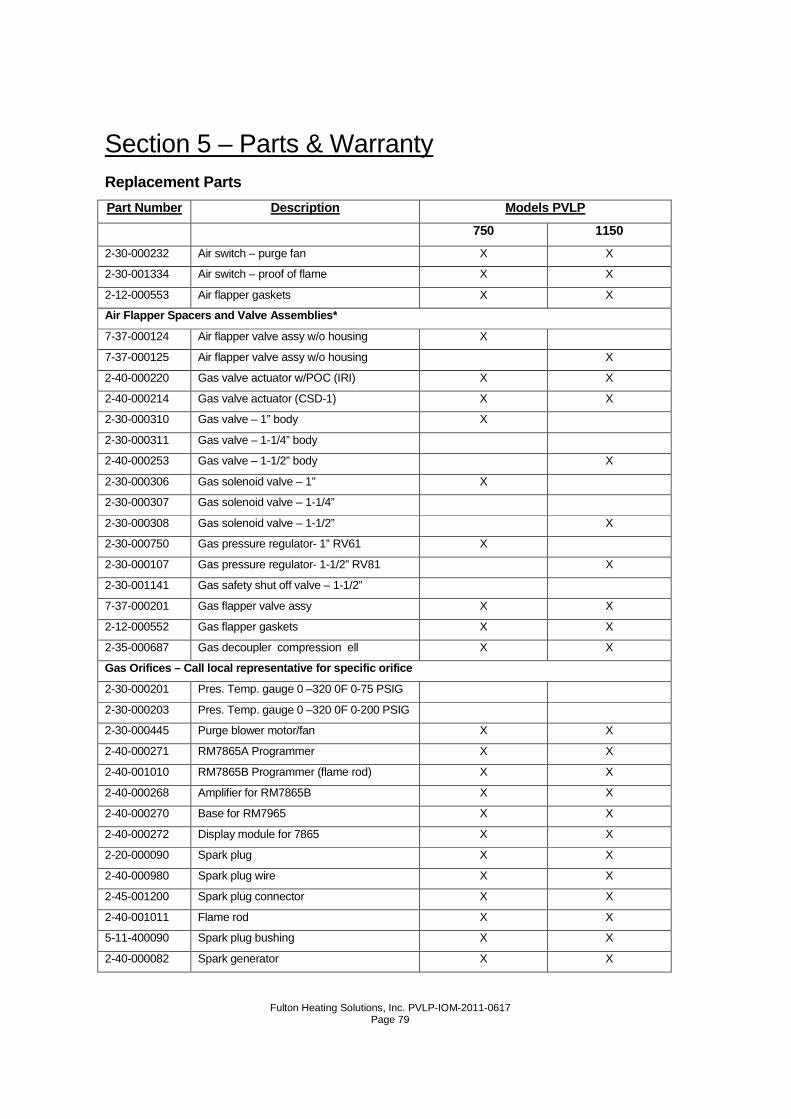
Fulton Heating Solutions, Inc. PVLP-IOM-2011-0617
Page 79
Section 5 – Parts & Warranty Replacement Parts
Part Number Description Models PVLP
750 1150
2-30-000232 Air switch – purge fan X X
2-30-001334 Air switch – proof of flame X X
2-12-000553 Air flapper gaskets X X
Air Flapper Spacers and Valve Assemblies*
7-37-000124 Air flapper valve assy w/o housing X
7-37-000125 Air flapper valve assy w/o housing X
2-40-000220 Gas valve actuator w/POC (IRI) X X
2-40-000214 Gas valve actuator (CSD-1) X X
2-30-000310 Gas valve – 1” body X
2-30-000311 Gas valve – 1-1/4” body
2-40-000253 Gas valve – 1-1/2” body X
2-30-000306 Gas solenoid valve – 1” X
2-30-000307 Gas solenoid valve – 1-1/4”
2-30-000308 Gas solenoid valve – 1-1/2” X
2-30-000750 Gas pressure regulator- 1” RV61 X
2-30-000107 Gas pressure regulator- 1-1/2” RV81 X
2-30-001141 Gas safety shut off valve – 1-1/2”
7-37-000201 Gas flapper valve assy X X
2-12-000552 Gas flapper gaskets X X
2-35-000687 Gas decoupler compression ell X X
Gas Orifices – Call local representative for specific orifice
2-30-000201 Pres. Temp. gauge 0 –320 0F 0-75 PSIG
2-30-000203 Pres. Temp. gauge 0 –320 0F 0-200 PSIG
2-30-000445 Purge blower motor/fan X X
2-40-000271 RM7865A Programmer X X
2-40-001010 RM7865B Programmer (flame rod) X X
2-40-000268 Amplifier for RM7865B X X
2-40-000270 Base for RM7965 X X
2-40-000272 Display module for 7865 X X
2-20-000090 Spark plug X X
2-40-000980 Spark plug wire X X
2-45-001200 Spark plug connector X X
2-40-001011 Flame rod X X
5-11-400090 Spark plug bushing X X
2-40-000082 Spark generator X X
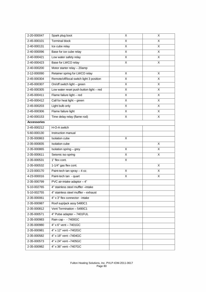
Fulton Heating Solutions, Inc. PVLP-IOM-2011-0617
Page 80
2-20-000047 Spark plug boot X X
2-45-000101 Terminal block X X
2-40-000131 Ice cube relay X X
2-40-000096 Base for ice cube relay X X
2-40-000421 Low water safety relay X X
2-40-000423 Base for LWCO relay X X
2-40-000200 Motor starter relay – 20amp
2-12-000090 Retainer spring for LWCO relay X X
2-45-000304 Remote/off/local switch light 3 position X X
2-45-000307 On/off switch light – green X X
2-45-000305 Low water reset push button light – red X X
2-45-000411 Flame failure light – red X X
2-45-000412 Call for heat light – green X X
2-45-000203 Light bulb only X X
2-45-000306 Flame failure light X X
2-40-000153 Time delay relay (flame rod) X X
Accessories
2-45-000212 H-O-A switch
5-60-000130 Instruction manual
2-35-000863 Isolation cube X
2-35-000835 Isolation cube X
2-35-000865 Isolation spring – grey X X
2-35-000611 Seismic iso spring X X
2-35-000531 1” flex cont. X
2-35-000532 1-1/4” gas flex cont. X
2-23-000170 Paint-tech tan spray – 4 oz. X X
4-23-000016 Paint-tech tan - quart X X
2-35-000799 PVC air-intake adaptor – 4”
5-10-002765 4” stainless steel muffler –intake
5-10-002755 4” stainless steel muffler – exhaust
2-35-000061 4” x 3” flex connector - intake
2-35-000987 Roof sup/jack assy 5480C1
2-35-000812 Vent Termination – 5490C1
2-35-000571 4” Pulse adapter – 7401FUL
2-35-000983 Rain cap - - 7400GC
2-35-000980 4” x 6” vent – 7401GC
2-35-000981 4” x 12” vent –7402GC
2-35-000582 4” x 18” vent –7404GC
2-35-000573 4” x 24” vent –7405GC
2-35-000982 4” x 36” vent –7407GC
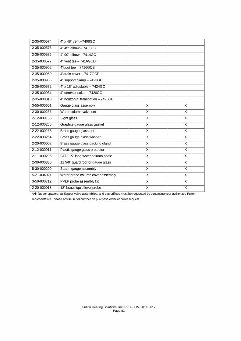
Fulton Heating Solutions, Inc. PVLP-IOM-2011-0617
Page 81
2-35-000574 4” x 48” vent –7408GC
2-35-000575 4” 45° elbow – 7411GC
2-35-000576 4” 90° elbow – 7414GC
2-35-000577 4” vent tee – 7416GCD
2-35-000962 4”boot tee – 7416GCB
2-35-000960 4”drain cover – 7417GCD
2-35-000985 4” support clamp – 7423GC
2-35-000572 4” x 18” adjustable – 7424GC
2-35-000984 4” strm/spt collar – 7426GC
2-35-000813 4” horizontal termination – 7490GC
3-55-000601 Gauge glass assembly X X
2-30-000255 Water column valve set X X
2-12-000185 Sight glass X X
2-12-000256 Graphite gauge glass gasket X X
2-22-000263 Brass gauge glass nut X X
2-22-000264 Brass gauge glass washer X X
2-20-000002 Brass gauge glass packing gland X X
2-12-000911 Plastic gauge glass protector X X
2-11-000206 STD. 15” long water column bottle X X
2-30-000330 11 5/8” guard rod for gauge glass X X
5-30-000200 Steam gauge assembly X X
5-21-004021 Water probe column cover assembly X X
3-50-000712 PVLP probe assembly kit X X
2-20-000013 18” brass liquid level probe X X
*Air flapper spacers, air flapper valve assemblies, and gas orifices must be requested by contacting your authorized Fulton
representative. Please advise serial number on purchase order or quote request.

Fulton Heating Solutions, Inc. PVLP-IOM-2011-0617
Page 82
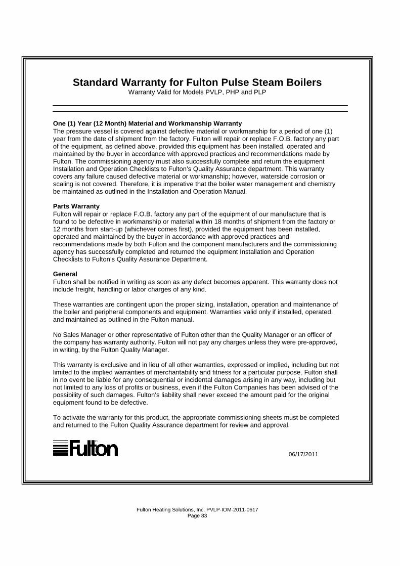
Fulton Heating Solutions, Inc. PVLP-IOM-2011-0617
Page 83
Standard Warranty for Fulton Pulse Steam Boilers Warranty Valid for Models PVLP, PHP and PLP
One (1) Year (12 Month) Material and Workmanship Wa rranty The pressure vessel is covered against defective material or workmanship for a period of one (1) year from the date of shipment from the factory. Fulton will repair or replace F.O.B. factory any part of the equipment, as defined above, provided this equipment has been installed, operated and maintained by the buyer in accordance with approved practices and recommendations made by Fulton. The commissioning agency must also successfully complete and return the equipment Installation and Operation Checklists to Fulton’s Quality Assurance department. This warranty covers any failure caused defective material or workmanship; however, waterside corrosion or scaling is not covered. Therefore, it is imperative that the boiler water management and chemistry be maintained as outlined in the Installation and Operation Manual. Parts Warranty Fulton will repair or replace F.O.B. factory any part of the equipment of our manufacture that is found to be defective in workmanship or material within 18 months of shipment from the factory or 12 months from start-up (whichever comes first), provided the equipment has been installed, operated and maintained by the buyer in accordance with approved practices and recommendations made by both Fulton and the component manufacturers and the commissioning agency has successfully completed and returned the equipment Installation and Operation Checklists to Fulton’s Quality Assurance Department. General Fulton shall be notified in writing as soon as any defect becomes apparent. This warranty does not include freight, handling or labor charges of any kind. These warranties are contingent upon the proper sizing, installation, operation and maintenance of the boiler and peripheral components and equipment. Warranties valid only if installed, operated, and maintained as outlined in the Fulton manual. No Sales Manager or other representative of Fulton other than the Quality Manager or an officer of the company has warranty authority. Fulton will not pay any charges unless they were pre-approved, in writing, by the Fulton Quality Manager. This warranty is exclusive and in lieu of all other warranties, expressed or implied, including but not limited to the implied warranties of merchantability and fitness for a particular purpose. Fulton shall in no event be liable for any consequential or incidental damages arising in any way, including but not limited to any loss of profits or business, even if the Fulton Companies has been advised of the possibility of such damages. Fulton’s liability shall never exceed the amount paid for the original equipment found to be defective. To activate the warranty for this product, the appropriate commissioning sheets must be completed and returned to the Fulton Quality Assurance department for review and approval.
06/17/2011

Fulton Heating Solutions, Inc. PVLP-IOM-2011-0617
Page 84

Fulton Heating Solutions, Inc. PVLP-IOM-2011-0617
Page 85

Fulton Heating Solutions, Inc. PVLP-IOM-2011-0617
Page 86

Fulton Heating Solutions, Inc. PVLP-IOM-2011-0617
Page 87

Fulton Heating Solutions, Inc. PVLP-IOM-2011-0617
Page 88
No part of this Installation, Operation, and Mainte nance manual may be reproduced in any form
or by any means without permission in writing from the Fulton Companies.
Fulton Boiler Works, Inc., Fulton Heating Solutions, Inc. & Fulton Thermal Corporation are part of the Fulton Group
of Companies, a global manufacturer of steam, hot water and thermal fluid heat transfer systems.
For more of the following patents apply to this unit: U.S. Patent Numbers 4856558, 4884963, 926789, 4951706 and 5, 145, 345.
Swiss Registration Numbers 119122 and 119243. Swedish Registration Numbers 51873 and 51874. German Patent Number
M9104923.7. Benelux Registration Numbers 21548-01/02, 03/04 and 21548-05/06. French Registration Numbers 0304011,
0304015, and 0304016. Other patents pending.