function sequence table (fst) user manual
TRANSCRIPT
Form Number A4625 Part Number D301058X012 September 2010
Function Sequence Table (FST) User Manual
Remote Automation Solutions

Function Sequence Table (FST) User Manual
ii Revised Sep-10
Revision Tracking Sheet
September 2010
This manual may be revised periodically to incorporate new or updated information. The revision date of each page appears at the bottom of the page opposite the page number. A change in revision date to any page also changes the date of the manual that appears on the front cover. Listed below is the revision date of each page (if applicable):
Page Revision All pages Sep-10 Initial issue Jan-04
NOTICE Remote Automation Solutions (“RAS”), division of Emerson Process Management shall not be liable for technical or editorial errors in this manual or omissions from this manual. RAS MAKES NO WARRANTIES, EXPRESSED OR IMPLIED, INCLUDING THE IMPLIED WARRANTIES OF MERCHANTABILITY AND FITNESS FOR A PARTICULAR PURPOSE WITH RESPECT TO THIS MANUAL AND, IN NO EVENT SHALL RAS BE LIABLE FOR ANY INCIDENTAL, PUNITIVE, SPECIAL OR CONSEQUENTIAL DAMAGES INCLUDING, BUT NOT LIMITED TO, LOSS OF PRODUCTION, LOSS OF PROFITS, LOSS OF REVENUE OR USE AND COSTS INCURRED INCLUDING WITHOUT LIMITATION FOR CAPITAL, FUEL AND POWER, AND CLAIMS OF THIRD PARTIES.
Bristol, Inc., Bristol Canada, BBI SA de CV and Emerson Process Management Ltd, Remote Automation Solutions division (UK), are wholly owned subsidiaries of Emerson Electric Co. doing business as Remote Automation Solutions (“RAS”), a division of Emerson Process Management. FloBoss, ROCLINK, Bristol, Bristol Babcock, ControlWave, TeleFlow and Helicoid are trademarks of RAS. AMS, PlantWeb and the PlantWeb logo are marks of Emerson Electric Co. The Emerson logo is a trademark and service mark of the Emerson Electric Co. All other trademarks are property of their respective owners.
The contents of this publication are presented for informational purposes only. While every effort has been made to ensure informational accuracy, they are not to be construed as warranties or guarantees, express or implied, regarding the products or services described herein or their use or applicability. RAS reserves the right to modify or improve the designs or specifications of such products at any time without notice. All sales are governed by RAS’ terms and conditions which are available upon request.
RAS does not assume responsibility for the selection, use or maintenance of any product. Responsibility for proper selection, use and maintenance of any RAS product remains solely with the purchaser and end-user.
© 2004-2010 Remote Automation Solutions, division of Emerson Process Management. All rights reserved.

Function Sequence Table (FST) User Manual
Contents
Chapter 1 – Introduction 1-1
1.1 FST Editor Overview ...................................................................................................................... 1-1 1.1.1 Device-specific Processing Considerations..................................................................... 1-2 1.1.2 The FST Results Register................................................................................................ 1-4
Chapter 2 – The FST Editor 2-1
2.1.1 Guidelines for Creating FSTs........................................................................................... 2-3 2.1.2 FSTs During Storage and Restart ................................................................................... 2-3 2.1.3 Label Field........................................................................................................................ 2-5 2.1.4 Command Field................................................................................................................ 2-6 2.1.5 Argument Fields............................................................................................................... 2-6 2.1.6 Comment Field................................................................................................................. 2-6
2.2 Creating an FST............................................................................................................................. 2-7 2.2.1 Creating an FST from an Existing File.............................................................................2-7
2.3 Managing FSTs.............................................................................................................................. 2-8 2.3.1 Compiling an FST ............................................................................................................ 2-8 2.3.2 Downloading an FST .......................................................................................................2-9 2.3.3 Saving an FST ...............................................................................................................2-11 2.3.4 Starting an FST..............................................................................................................2-11 2.3.5 Stopping an FST ............................................................................................................2-12 2.3.6 Clearing an FST.............................................................................................................2-13 2.3.7 Reading an FST from a Device......................................................................................2-13 2.3.8 Reading an FST from a File...........................................................................................2-13 2.3.9 Closing an FST ..............................................................................................................2-14 2.3.10 Printing an FST ..............................................................................................................2-14 2.3.11 Editing an FST ...............................................................................................................2-15
2.4 Troubleshooting an FST...............................................................................................................2-15 2.4.1 Monitoring an FST .........................................................................................................2-16 2.4.2 Tracing an FST ..............................................................................................................2-20
Chapter 3 – Command Library 3-1
3.1.1 Command Descriptions.................................................................................................... 3-3 3.1.2 Defining a FST History Point..........................................................................................3-11
Chapter 4 – Example FSTs 4-1
4.1 Implementing Specific Commands................................................................................................. 4-1 4.1.1 Mathematical Commands ................................................................................................ 4-1 4.1.2 Logical Commands .......................................................................................................... 4-4 4.1.3 Comparison Commands .................................................................................................. 4-5 4.1.4 Time-Related Commands ................................................................................................ 4-5 4.1.5 Control-Related Commands ............................................................................................ 4-7 4.1.6 Database Commands ...................................................................................................... 4-9 4.1.7 Miscellaneous Commands............................................................................................... 4-9
4.2 Application-based Examples........................................................................................................4-10 4.2.1 Writing Data to a History Point.......................................................................................4-10
Revised Sep-10 iii

Function Sequence Table (FST) User Manual
4.2.2 Stopping an FST............................................................................................................ 4-12 4.2.3 Cycling an FST on a Periodic Basis .............................................................................. 4-13 4.2.4 Calculating an Approximate Execution Rate ................................................................. 4-13 4.2.5 Submitting Data to the Historical Database................................................................... 4-14
Index I-1
iv Revised Sep-10

FST User Manual
Chapter 1 – Introduction
ROCLINK 800’s Function Sequence Table (FST) utility provides a command-based programming language that enables you to define a set of actions that the system performs when a set of specific conditions occurs.
You can write FSTs specifically for applications that require special control features, such as logic sequencing. For example, an FST can initiate emergency shutdown control when a parameter exceeds a low or high limit. You program and configure FSTs using the FST Editor, which is included in ROCLINK 800 (Utilities > FST Editor).
An FST defines the input-to-output (I/O) relationships in the device through a set of user-selected instructions, called functions. Functions define the specific actions to be performed in a specific sequence. Functions normally execute in top-to-bottom order. However, you can alter the execution sequence using decision-making functions.
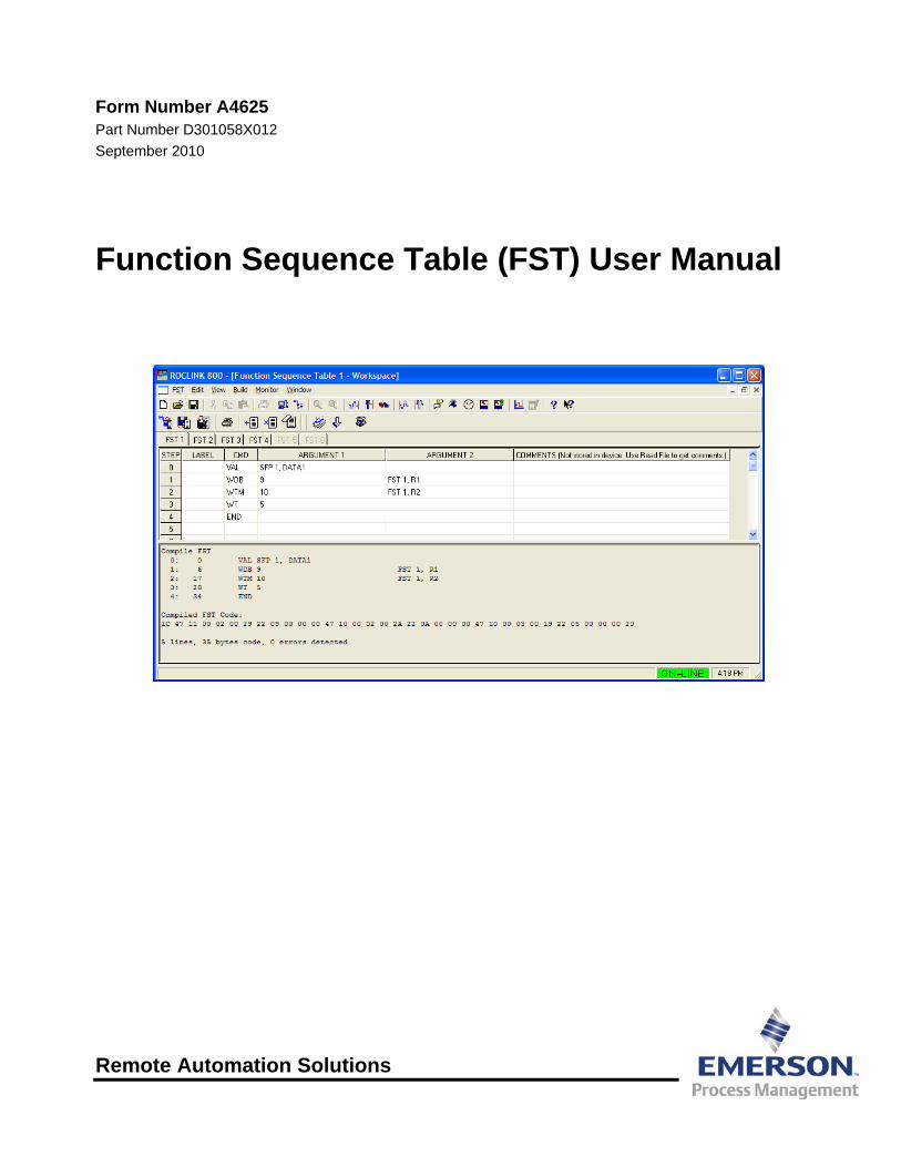
Functions consist of an optional label, a command, and one or two arguments. Figure 1-1 shows several functions on a FST editing workspace:
Figure 1-1. FST Functions
1.1 FST Editor Overview You build an FST from a library of commands that provide mathematical and logical operations, database access operations, historical commands, testing, branching operations, and control-related operations. Table 1-1 displays FST capabilities.
Table 1-1. FST Functionality
Device
Maximum Number of FSTs
Maximum Byte Size per FST
Maximum Line Length1
FloBoss 107 4 3000 400 ROC800-Series 6 3000 500
FloBoss 100-Series 2 3000 300 FloBoss 407 4 80002 300
Revised Sep-10 Introduction 1-1

FST User Manual
Device
Maximum Number of FSTs
Maximum Byte Size per FST
Maximum Line Length1
ROC300-Series 4 80002 300 FloBoss 500-Series 2 4000 300
1Maximum Line Length is a limit of the FST Editor. 2Total FST space in ROC300-Series and FloBoss 407 devices is 8000 bytes. Individual FST size is not limited, but the sum of all FSTs cannot exceed 8000 bytes.
Each FST may consist of as many functions as you can fit into the memory reserved for FSTs in the device. Reserved memory is pre-determined by the device with a set amount of steps allocated for each FST. The byte size of an FST displays in the Code Size field on the Advanced tab of the FST Registers screen (Configure > Control > FST Registers):
Figure 1-2. FST Registers screen
Note: Byte size also displays when you compile a project.
Caution Because of the potential loading increase on the system, we recommend that you monitor the Master Processor Unit (MPU) loading value (as displayed on the Other Information tab on the Device Information screen [ROC > Information]) to ensure that the FST is not consuming too much of the MPU’s resources.
1.1.1 Device-specific Processing Considerations ROCLINK 800 processes FSTs differently for each device:
FloBoss 107 By default, each FST executes 20 instructions in any 50-millisecond cycle. You can configure both the number of instructions (between 1 and 250 per cycle) as well as the length of a cycle (100 ms, 50, or 1 second). Factors affecting this performance include processor load (during the interval), instruction, and argument type.
1-2 Introduction Revised Sep-10

FST User Manual
Revised Sep-10 Introduction 1-3
To configure the number of instructions executed, select ROC > Information. On the Device Information screen, complete the FST Execution field with a value between 1 and 250 to indicate the number of executions per cycle (a cycle being the execution period, which is 1 second). Click Apply.
To configure the length of a cycle (which corresponds to the CPU scan rate), click on the CPU module in the FB107’s dynamic interface. Select the Advanced tab on the screen that appears below the FB107 graphic, and select a Scan Rate.
ROC800-Series Each FST executes up to ten instructions in any given 100-millisecond interval. However, this does not guarantee that 10 instructions execute for a given FST within a given 100 millisecond interval. Factors affecting this performance include processor load (during the interval), instruction, and argument type (constant or value from other tasks, such as meter runs). When six FSTs are running, a maximum of 60 steps execute.
FloBoss 100-Series Each FST executes a configurable number of instructions per second. By default, the FST executes 20 instructions per execution period. If an FST has 30 sequential instructions, the first 20 instructions execute during the current execution period and remaining 10 instructions execute during the next execution period. To configure the number of instructions executed, select ROC > Information. On the Device Information screen, complete the FST Execution field with a value between 1 and 100 to indicate the number of executions per cycle (a cycle being the execution period, which is 1 second). Click Apply.
The new number of instructions to execute takes effect in the next execution period. Restart is not required.
FloBoss 407 and
ROC300-Series
Each FST executes as many instructions of FST code as processor free time allows every 100 milliseconds. When a time slice completes, another task is given the opportunity to execute. If the FST task does not complete in the allotted time, the FST task uses whatever time is left over from other tasks to attempt to complete the sequence of functions. If the FST task executes in less than the allotted time, the operating system uses the remaining time to perform other tasks.
FloBoss 500-Series Each FST executes up to ten instructions in any given 100 millisecond interval. That does not guarantee that 10 instructions execute for a given FST within a 100 millisecond interval. Factors affecting this performance include processor load (during the interval), instruction, and argument type (constant or value from other tasks, such as meter runs). When two FSTs are running, a maximum of 20 steps execute.

FST User Manual
Note: To reduce processor loading, use WAIT (WT) commands. To prevent an endless loop, include an END command at the end of your FST.
As the sequence of functions executes, two memory locations store intermediate results from one function to the next. The Results Register (RR) stores a floating-point value referred to
as the Signal Value Analog (SVA). The Compare Flag (CF) stores a discrete value called the Signal
Value Discrete (SVD).
Depending on the command, the Results Register (RR) and the Compare Flag (CF) may be loaded, stored, tested, modified, or left unchanged.
Note: Since a Restart always clears FST registers (including the Run Flag), use softpoints (or any other valid TPL) to load initial values for the FST.
1.1.2 The FST Results Register The FST Editor uses special softpoints called registers to store FST-related information such as calculated values. You use the SAV (Save) command to write a value to a register and the VAL (Value) command to read a value from a register. These registers also enable different FSTs to share information.
Note: Using the Results Register (RR) is optional. An FST can run without pre-defining register values through these screens.
To access the registers:
1. Select Configure > Control > FST Registers from the ROCLINK 800 menu bar. The FST Registers screen displays.
Figure 1-3. FST Registers, General tab (ROC800-Series)
Figure 1-4. FST Registers, General tab
1-4 Introduction Revised Sep-10
FST User Manual
Revised Sep-10 Introduction 1-5
Note: The format for the ROC800-Series FST Registers screen (for both the General and Advanced tabs) differs slightly from the format for other devices.
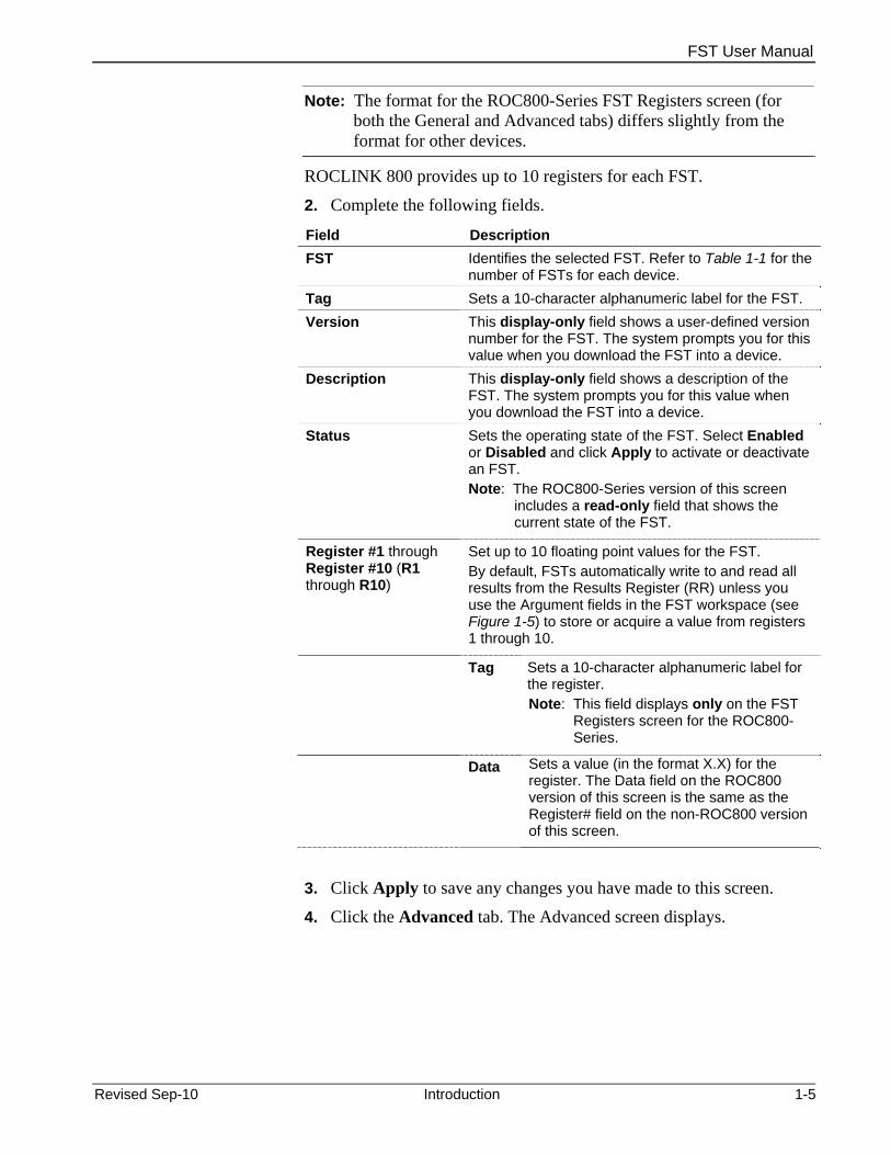
ROCLINK 800 provides up to 10 registers for each FST.
2. Complete the following fields.
Field Description FST Identifies the selected FST. Refer to Table 1-1 for the
number of FSTs for each device. Tag Sets a 10-character alphanumeric label for the FST. Version This display-only field shows a user-defined version
number for the FST. The system prompts you for this value when you download the FST into a device.
Description This display-only field shows a description of the FST. The system prompts you for this value when you download the FST into a device.
Status Sets the operating state of the FST. Select Enabled or Disabled and click Apply to activate or deactivate an FST. Note: The ROC800-Series version of this screen
includes a read-only field that shows the current state of the FST.
Register #1 through Register #10 (R1 through R10)
Set up to 10 floating point values for the FST. By default, FSTs automatically write to and read all results from the Results Register (RR) unless you use the Argument fields in the FST workspace (see Figure 1-5) to store or acquire a value from registers 1 through 10.
Tag Sets a 10-character alphanumeric label for the register. Note: This field displays only on the FST
Registers screen for the ROC800-Series.
Data Sets a value (in the format X.X) for the register. The Data field on the ROC800 version of this screen is the same as the Register# field on the non-ROC800 version of this screen.
3. Click Apply to save any changes you have made to this screen.
4. Click the Advanced tab. The Advanced screen displays.

FST User Manual
Figure 1-5. FST Registers, Advanced tab (ROC800-Series)
Figure 1-6. FST Registers, Advanced tab
5. Complete the following fields.
Field Description Timer #1 through Timer #4
Sets up to four timers an FST can use to control processing. The FST automatically updates the value in these fields, decrementing it by 1 every 100 milliseconds. For example, if you set a field to 100, it reaches 0 after 1 minute. Typically, you use the Check Timer (CT) function (refer to Section 1.4, Command Library) with the Timer fields to perform branching.
Misc #1 through Misc #4
Sets up to four fields which contain unsigned 8-bit integers (with valid decimal values of 0 to 255) the FST can use for global storage.
Mesg #1 and Mesg #2 Defines two 30-character alphanumeric messages that display in the FST message area
Msg Data #1 and #2 These read-only fields show any values associated with the messages.
Code Size This read-only field shows the total bytes the FST uses.
Code Pointer Byte This read-only field shows the offset of the next function queued for execution from the beginning of its memory segment. Since this value changes very rapidly unless the FST is at a Wait (WT) command, it is typically used for debugging FSTs. Note: This field is called Code Pointer in the
ROC800-Series version of this screen.
Execution Delay Sets the amount of time between the execution of successive command steps in an FST. The default value is 0; the minimum delay you can set is 0.1 seconds.
1-6 Introduction Revised Sep-10

FST User Manual
Revised Sep-10 Introduction 1-7
Field Description Result Register Contains the floating point result from the most
current executed command. This field is also called the Signal Value Analog (SVA). Typically the FST completes this field; it is user-defined usually in Trace mode (see Section 1.3, FST Trace Mode).
Compare Flag Contains an 8-bit integer between 0 and 255 that is manipulated by the FST logic functions (see Section B.4, Command Library). Typically the FST completes this field; it is user-defined usually in Trace mode (see Section 1.3, FST Trace Mode).
Steps/Task Cycle Sets the number of steps per task cycle. Note: This field appears only on the ROC800-
Series version of this screen.
FST Cycle Time This read-only field shows, in seconds, the currently defined cycle time. Note: This field appears only on the ROC800-
Series version of this screen.
As noted, using the Results Register (RR) is optional. You can create and run an FST without pre-defining register values through these screens.

FST User Manual
1-8 Introduction Revised Sep-10
[This page is intentionally left blank.]
FST User Manual
Chapter 2 – The FST Editor
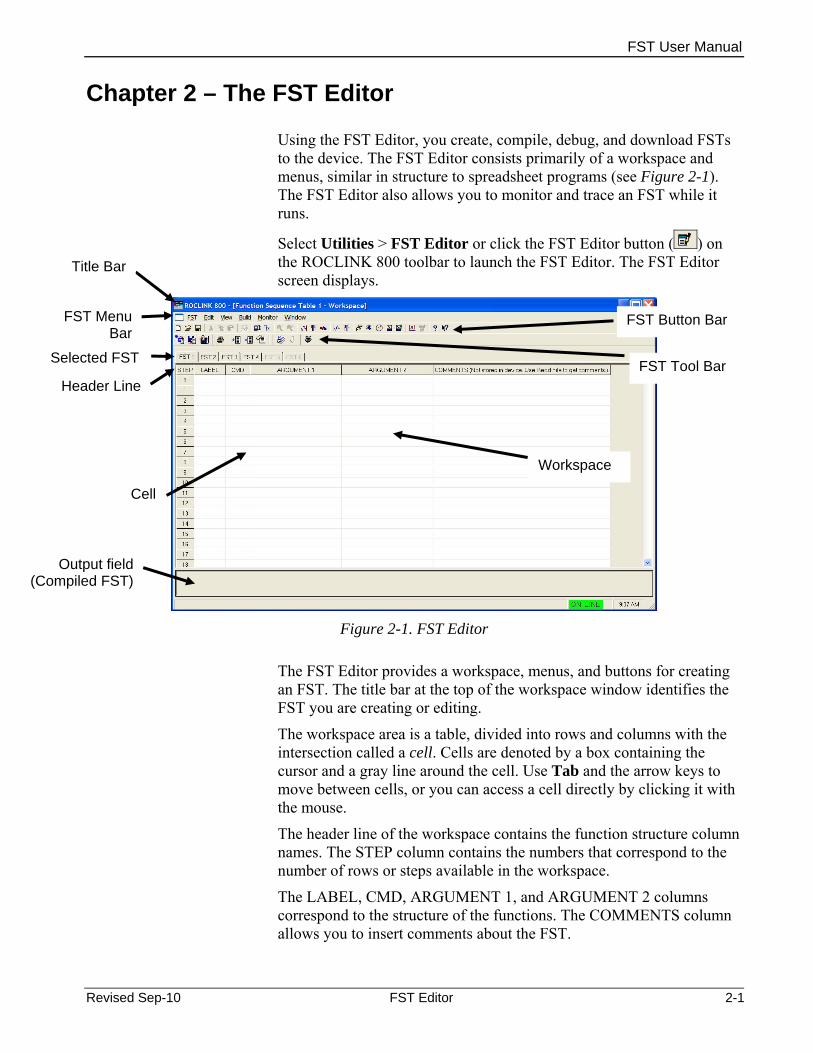
Using the FST Editor, you create, compile, debug, and download FSTs to the device. The FST Editor consists primarily of a workspace and menus, similar in structure to spreadsheet programs (see Figure 2-1). The FST Editor also allows you to monitor and trace an FST while it runs.
Select Utilities > FST Editor or click the FST Editor button ( ) on the ROCLINK 800 toolbar to launch the FST Editor. The FST Editor screen displays.
Title Bar
Selected FST
FST Menu Bar
FST Tool Bar
FST Button Bar
Header Line
Workspace
Cell
Output field (Compiled FST)
Figure 2-1. FST Editor
The FST Editor provides a workspace, menus, and buttons for creating an FST. The title bar at the top of the workspace window identifies the FST you are creating or editing.
The workspace area is a table, divided into rows and columns with the intersection called a cell. Cells are denoted by a box containing the cursor and a gray line around the cell. Use Tab and the arrow keys to move between cells, or you can access a cell directly by clicking it with the mouse.
The header line of the workspace contains the function structure column names. The STEP column contains the numbers that correspond to the number of rows or steps available in the workspace.
The LABEL, CMD, ARGUMENT 1, and ARGUMENT 2 columns correspond to the structure of the functions. The COMMENTS column allows you to insert comments about the FST.
Revised Sep-10 FST Editor 2-1

FST User Manual
2-2 FST Editor Revised Sep-10
Note: Comments do not download; they are only included in the FST when you save it to a file.
Table 2-1 shows keys and commands you can use to manipulate and move around the FST workspace.
Table 2-1. Workspace and Output Keystrokes
Key Action → Move cursor to the right cell or character.
← Move cursor to the left cell or character.
↑ Move cursor to the cell above it.
↓ Move cursor to the cell below it. Backspace Delete the previous character. Ctrl + Home Move cursor to top left cell of Workspace. Ctrl + End Move cursor to bottom right cell of Workspace.
Delete Delete character in front of the cursor position. End Within a cell, move cursor to the right-most position within the cell.
Within a row, move cursor to the right-most position in the row Enter Process saves contents of cell entry and moves to the next cell. Esc Undo entry and display original or prior contents of the cell. F1 Help.
Home Within a cell, move cursor to the left-most position within the cell. Within a row, move cursor to the left-most position within the row.
Page Down Display next page of Workspace. Page Up Display previous page of Workspace
Tab Move to the next cell.
FST Function Structure
Each function consists of a STEP number, an optional LABEL, a command (CMD), and up to two arguments (ARGUMENT 1 and ARGUMENT 2). See Table 2-2.
Table 2-2. FST Function Structure
STEP LABEL CMD ARGUMENT 1 ARGUMENT 2 0
The FST program automatically provides the step numbers for each FST. You complete the other fields in the structure to build a function.
Note: Do not skip any steps. The FST program treats a blank step as the end of a program and does not compile correctly.

FST User Manual
Revised Sep-10 FST Editor 2-3
2.1.1 Guidelines for Creating FSTs When you create FSTs, note the following guidelines:
Every FST requires one and only one END command. The END command tells the FST to return to the first step and to run either from the first line (step 0) or from the step where the FST begins.
Note: When you compile, the FST Editor automatically converts the first blank line it finds to an END command. Any commands after that blank line are lost and the FST may not compile correctly. Do not skip any steps in an FST.
To prevent overloading the MPU processor, structure your FST to avoid “infinite loops” (where the FST runs without successfully ending). Direct the program flow to the END command. You can use a branching function to force the FST to immediately return to step 0 if you do not want to wait for the next execution cycle to begin.
Use Wait states (WT command) to suspend operation of the FST whenever possible to reduce MPU processor overload, especially in an intentional loop in which a condition is being repeatedly checked.
Configure I/O parameters before you reference them in an FST. If you use any branching commands (GO, <, >, <=, >=, ==), make
sure that you first define the label that the command references. An FST will not compile if it attempts to write to a read-only (R/O)
field. However, if the field switches between read-write (R/W) and R/O, the FST will initially compile but will halt and fail if the field becomes R/O and the FST attempts to write to it.
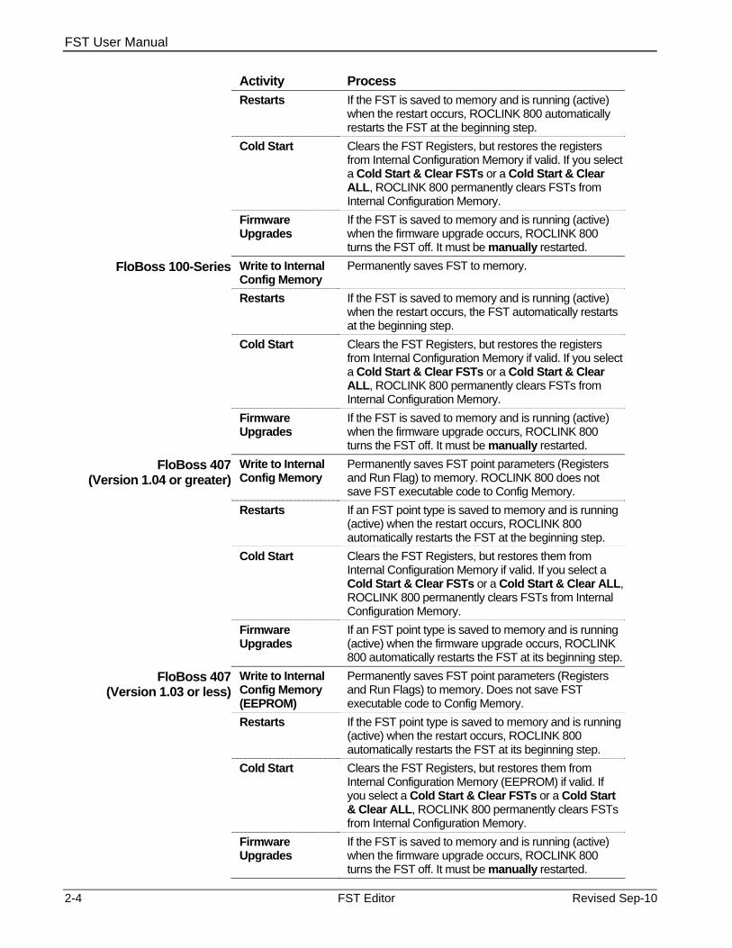
2.1.2 FSTs During Storage and Restart During storage and restart procedures, ROCLINK 800 handles FST information differently for each device.
Activity Process FloBoss 107 Write to Internal
Config Memory Permanently saves FST to memory.
Restart If the FST is saved to memory and is running (active) when the restart occurs, ROCLINK 800 automatically restarts the FST at the beginning step.
Cold Start Clears the FST Registers, but restores the registers from Internal Configuration Memory if valid. If you select a Cold Start & Clear FSTs or a Cold Start & Clear ALL, ROCLINK 800 permanently clears FSTs from Internal Configuration Memory.
Firmware Upgrades
If the FST is saved to memory and is running (active) when the firmware upgrade occurs, ROCLINK 800 turns the FST off. It must be manually restarted.
ROC800-Series Write to Internal Config Memory
Permanently saves FST to memory.
FST User Manual
2-4 FST Editor Revised Sep-10
Activity Process Restarts If the FST is saved to memory and is running (active)
when the restart occurs, ROCLINK 800 automatically restarts the FST at the beginning step.
Cold Start Clears the FST Registers, but restores the registers from Internal Configuration Memory if valid. If you select a Cold Start & Clear FSTs or a Cold Start & Clear ALL, ROCLINK 800 permanently clears FSTs from Internal Configuration Memory.
Firmware Upgrades
If the FST is saved to memory and is running (active) when the firmware upgrade occurs, ROCLINK 800 turns the FST off. It must be manually restarted.
FloBoss 100-Series Write to Internal Config Memory
Permanently saves FST to memory.
Restarts If the FST is saved to memory and is running (active) when the restart occurs, the FST automatically restarts at the beginning step.
Cold Start Clears the FST Registers, but restores the registers from Internal Configuration Memory if valid. If you select a Cold Start & Clear FSTs or a Cold Start & Clear ALL, ROCLINK 800 permanently clears FSTs from Internal Configuration Memory.
Firmware Upgrades
If the FST is saved to memory and is running (active) when the firmware upgrade occurs, ROCLINK 800 turns the FST off. It must be manually restarted.
FloBoss 407 (Version 1.04 or greater)
Write to Internal Config Memory
Permanently saves FST point parameters (Registers and Run Flag) to memory. ROCLINK 800 does not save FST executable code to Config Memory.
Restarts If an FST point type is saved to memory and is running (active) when the restart occurs, ROCLINK 800 automatically restarts the FST at the beginning step.
Cold Start Clears the FST Registers, but restores them from Internal Configuration Memory if valid. If you select a Cold Start & Clear FSTs or a Cold Start & Clear ALL, ROCLINK 800 permanently clears FSTs from Internal Configuration Memory.
Firmware Upgrades
If an FST point type is saved to memory and is running (active) when the firmware upgrade occurs, ROCLINK 800 automatically restarts the FST at its beginning step.
FloBoss 407 (Version 1.03 or less)
Write to Internal Config Memory (EEPROM)
Permanently saves FST point parameters (Registers and Run Flags) to memory. Does not save FST executable code to Config Memory.
Restarts If the FST point type is saved to memory and is running (active) when the restart occurs, ROCLINK 800 automatically restarts the FST at its beginning step.
Cold Start Clears the FST Registers, but restores them from Internal Configuration Memory (EEPROM) if valid. If you select a Cold Start & Clear FSTs or a Cold Start & Clear ALL, ROCLINK 800 permanently clears FSTs from Internal Configuration Memory.
Firmware Upgrades
If the FST is saved to memory and is running (active) when the firmware upgrade occurs, ROCLINK 800 turns the FST off. It must be manually restarted.

FST User Manual
Revised Sep-10 FST Editor 2-5
Activity Process ROC300-Series Write to Internal
Config Memory (EEPROM)
Permanently saves FST point parameters (Registers and Run Flags) to memory. Does not save FST executable code to Config Memory.
Restarts If the FST point type is saved to memory and is running (active) when the restart occurs, ROCLINK 800 automatically restarts the FST at its beginning step.
Cold Start Clears the FST Registers, but restores them from Internal Configuration Memory (EEPROM) if valid. If you select a Cold Start & Clear FSTs or a Cold Start & Clear ALL, ROCLINK 800 permanently clears FSTs from Internal Configuration Memory.
Firmware Upgrades
If an FST point type is saved to memory and is running (active) when the firmware upgrade occurs, ROCLINK 800 automatically restarts the FST at its beginning step.
FloBoss 500-Series Write to Internal Config Memory
Permanently saves FST to memory.
Restarts If the FST is saved to memory and is running (active) when the restart occurs, ROCLINK 800 automatically restarts the FST at its beginning step.
Cold Start Clears the FST Registers, but restores them from Internal Configuration Memory if valid. If you select a Cold Start & Clear FSTs or a Cold Start & Clear ALL, ROCLINK 800 permanently clears FSTs from Internal Configuration Memory.
Firmware Upgrades
If the FST is saved to memory and is running (active) when the firmware upgrade occurs, ROCLINK 800 automatically restarts the FST at its beginning step.
2.1.3 Label Field The optional Label field allows you to uniquely identify a function. A label consists of up to six alphanumeric characters in any combination. A common practice is to use the label to identify the action the function performs. For example, the label “PUMPON” describes a function that activates a pump.
Note: Do not use the names of commands as labels.
Labels enable branching, the ability to direct the execution to a function other than the next function in the sequence. Table 2-1 shows an example of branching. Step 0 instructs the program to GO to the label PMPOFF, as established by Argument 1 in step 0. The program then branches to step 2, where the LABEL PMPOFF is located, and performs that function.
Table 2-3. FST Label Field
STEP LABEL CMD ARGUMENT 1 ARGUMENT 20 GO PMPOFF 1 PUMPON DO DOU 4-1 1

FST User Manual
2-6 FST Editor Revised Sep-10
STEP LABEL CMD ARGUMENT 1 ARGUMENT 22 PMPOFF DO DOU 4-2 0
2.1.4 Command Field The FST command (CMD) field specifies the action a function takes. Each command cell provides a drop-down list that shows the function commands and provides a brief description of how they operate on the RR, CF, and Argument values. You can also type commands directly. Table 2-2 shows the use of the GO command. Refer to Chapter 3 for a summary of each command.
Table 2-4. FST Command Field
STEP LABEL CMD ARGUMENT 1 ARGUMENT 2 0 GO PMPOFF . .
12 PMPOFF VAL 3
2.1.5 Argument Fields Depending on the command, arguments can be unused, references to parameters in the FloBoss (TLPs), numerical constants, or ASCII characters. Once you select a command, the argument cell requires that you either type in a numerical constant or ASCII text or click the TLP button for data selection. Depending on whether you have selected TLPs to display as numbers or as text (via Tools > Options in ROCLINK 800), the TLP appears in the argument cells as a number sequence or as a text abbreviation of the Type, Point number and Parameter. For example, the text abbreviation of the status parameter of discrete input module 4 channel 1 would be DIN4-1,STATUS. The Data #3 parameter for softpoint 3 would be SFP 3,DATA3.
2.1.6 Comment Field Use the Comment field to enhance readability and provide a place to document the purpose of an FST, Step, group of Steps, and save information within the FST. Comments are discarded when an FST is compiled and downloaded to the device. Comments remain with the FST when it is saved to a disk file.
Note: When you download or print an FST, the FST removes comments. Comments exist only in the electronic file.
FST Function Examples
A function consists of a command, its associated arguments, and an optional label. In the example shown in Table B-6, the Value (VAL) command in Step 0 writes the current process value of analog input

FST User Manual
(module 3, channel 1) in EUs to the Result Register (RR), which is implied. The label in this example (CKHIAL) serves only as a comment, since no other function branches to it.
Table 2-5. FST Function Examples
STEP LABEL CMD ARGUMENT1 ARGUMENT2 0 CKHIAL VAL AIN 3-1,EU 1 >= AIN 3-1,HIAL PUMPON
In this example, when the RR value from step 1 equals or exceeds (>=) the High Alarm value (VAL) in step 2 and the High Alarm limit (HIAL) condition is met, the FST branches to the PUMPON label to turn the pump on.
2.2 Creating an FST You can create an FST either by entering the steps in a blank workspace or by editing an existing file from a device or from a disk file.
To create an FST while on-line with a device:
1. Start the ROCLINK 800 software and connect to the device.
2. Select Utilities > FST Editor.
3. Select the tab of the FST (FST 1 through FST 6, depending on the device).
4. Fill in each step with the appropriate labels, commands, tags, and arguments.
When you select the Command field, the button appears. Click this button to display a list of commands from which to choose. Alternately, you can type the three-character command in the Command field.
Depending upon which command you choose, the argument fields prompt you to type in a label, choose a TLP, or enter some other data.
The Label field is optional, but are may be required if you are using a label within a command. Enter all required labels to prevent a compile error.
Place an End command at the end of your FST.
2.2.1 Creating an FST from an Existing File Use the following steps to create an FST by editing an existing FST. You may use either a FST from the device or a FST file on your PC.
If you are using a file from the device, connect the device to the computer running ROCLINK 800 software.
1. Select Utilities > FST Editor.
Revised Sep-10 FST Editor 2-7

FST User Manual
2. Select File > Read > From File or File > Read > From Device.
3. Open an existing FST file with the .FST extension.
4. Edit each step with the appropriate command, label, and arguments.
The Label field is optional, but may be required if you are using the label within a command. Enter all required labels to prevent a compile error.
When you select the Command field, the button appears. Click this button to display a list of commands from which to choose. Alternately, you can type the three-character command in the Command field.
Depending upon which command you choose, the Argument fields prompt you to type in a label, choose a TLP, or enter some other data.
Place an End command at the end of your FST.
2.3 Managing FSTs Once you create an FST, you must compile it into a machine-readable format, which also verifies its functionality. If the compile is successful, you can then download the FST to the intended device. Once you’ve loaded the FST to the device, you can start it, stop it, and clear (delete) it. You can also “read” (copy) an FST from a device into the FST workspace and print an FST (minus its comments).
Note: You cannot load an FST into a device that is already running an FST. You must first stop the current FST.
2.3.1 Compiling an FST To compile an FST:
Select Build > Compile or click Compile FST on the FST Editor toolbar (see Figure 2-2).
Figure 2-2. FST Editor Toolbar: Compile FST
The compiled file displays in the Output FST field (see Figure 2-3).
2-8 FST Editor Revised Sep-10

FST User Manual
Figure 2-3. Compiled FST
If invalid points exist in the FST during compilation, you receive an error indicating which point number is missing.
Note: If an error occurs during the compile process, the Output field lists the error type and the cell in question turns red. Correct all errors and recompile.
Compile errors may occur when you: Enter invalid arguments or commands in the FST. Perform a compile. The error displays in the Output field (at the
bottom of the FST workspace). Open an FST from a device or disk file.
2.3.2 Downloading an FST Once you have successfully compiled an FST, you can download it to the device’s memory:
1. Select File > Download or click Download on the FST Editor toolbar (see Figure 2-4).
Compiled version of FST in Output field
Revised Sep-10 FST Editor 2-9

FST User Manual
Figure 2-4. FST Editor Toolbar: Download
Note: The Download button activates only after you successfully compile an FST.
2. If the device already has a running FST, the FST Editor prompts you either to stop the FST and continue with the download or to stop the FST without downloading.
Figure 2-5. FST Details Dialog
Note: This prompt appears only if the device is currently running an FST.
3. Click Yes to stop the running FST and replace it. (If you click No the download ends.) The FST Details screen displays.
4. Enter a version number and description of the FST, for later identification, and click OK.
Figure 2-6. FST Details Dialog
Note: This step is not required, but is extremely helpful when you need to identify or debug your FST.
A verification dialog displays indicating that the download was successful.
2-10 FST Editor Revised Sep-10

FST User Manual
5. Click Yes to start the FST.
How Many FSTs?
The number of FSTs a device can manage depends on the device and the complexity (line length and byte size) of the FST. Refer to Table 1-1 for device and FST capacities.
2.3.3 Saving an FST To save the FST as an individual disk file:
1. Select FST > Save To .FST File or click Save to .FST File on the FST Editor toolbar (see Figure 2-7).
Figure 2-7. FST Editor Toolbar
A Save As dialog displays.
2. Enter a file name and click Save. The FST Editor saves the file in
the location you specify with an .fst extension.
2.3.4 Starting an FST Once your FST compiles successfully and you download it to the device, you have to start the FST before it can run. Depending on your device, you can have up to six FSTs running at one time. See Table 1-1 for the device-specific FST availabilities.
Using the FST Registers screen, you select a one of the device’s available FST “slots.” For example, a ROC800-Series allows you to define and run six FSTs at one time; an FB107 only allows you to define and run 4 FSTs at one time).
Revised Sep-10 FST Editor 2-11
FST User Manual
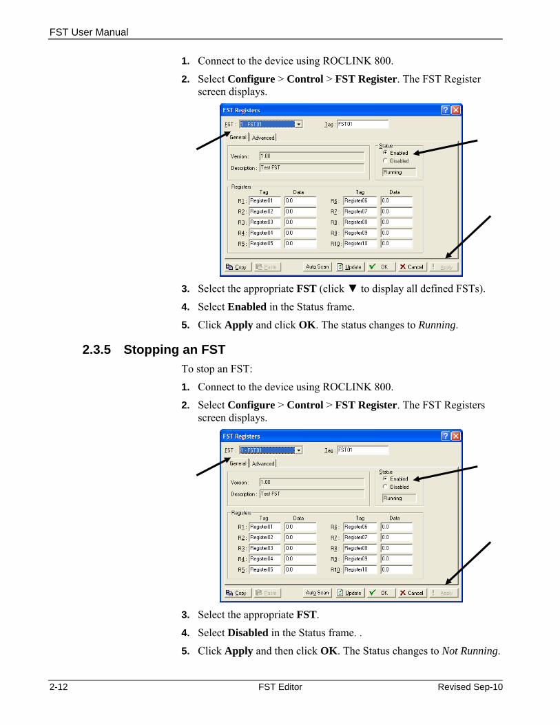
1. Connect to the device using ROCLINK 800.
2. Select Configure > Control > FST Register. The FST Register screen displays.
3. Select the appropriate FST (click ▼ to display all defined FSTs).
4. Select Enabled in the Status frame.
5. Click Apply and click OK. The status changes to Running.
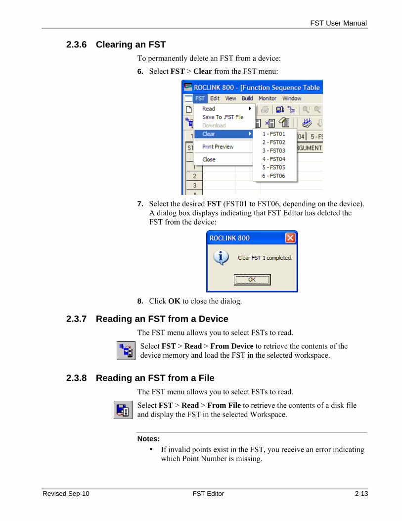
2.3.5 Stopping an FST To stop an FST:
1. Connect to the device using ROCLINK 800.
2. Select Configure > Control > FST Register. The FST Registers screen displays.
3. Select the appropriate FST.
4. Select Disabled in the Status frame. .
5. Click Apply and then click OK. The Status changes to Not Running.
2-12 FST Editor Revised Sep-10
FST User Manual
2.3.6 Clearing an FST To permanently delete an FST from a device:
6. Select FST > Clear from the FST menu:
7. Select the desired FST (FST01 to FST06, depending on the device).
A dialog box displays indicating that FST Editor has deleted the FST from the device:
8. Click OK to close the dialog.
2.3.7 Reading an FST from a Device The FST menu allows you to select FSTs to read.
Select FST > Read > From Device to retrieve the contents of the device memory and load the FST in the selected workspace.
2.3.8 Reading an FST from a File The FST menu allows you to select FSTs to read.
Select FST > Read > From File to retrieve the contents of a disk file and display the FST in the selected Workspace.
Notes:
If invalid points exist in the FST, you receive an error indicating which Point Number is missing.
Revised Sep-10 FST Editor 2-13

FST User Manual
The FST Editor populated the Output view with data either when you compile or when you read an FST from the device.
2.3.9 Closing an FST To exit the FST Editor:
Select FST > Close from the FST menu. The FST Editor closes, displaying the device’s ROCLINK 800 home screen.
Note: Use this same process to exit the Monitor FST, in which case you return to the FST Editor workspace.
2.3.10 Printing an FST A printed FST can help you in troubleshooting. To print an FST or export it to one of several file formats:
1. Select FST > Print Preview on the FST menu. The Print Preview screen displays:
2. Select one of several print or export options:
Click… To… Print Print the FST to a printer you select. PDF Save the FST as an Adobe® Acrobat® .PDF file to a name and
location you select. Excel Save the FST as a Windows® Microsoft® Excel® spreadsheet to
a name and location you select. RTF Save the FST as a Microsoft Word® Rich Text Format file to a
name and location you select. TXT Save the FST as an ASCII text file to a name and location you
select.
2-14 FST Editor Revised Sep-10
HTML Save the FST as a Hypertext Markup Language file to a name and location you select.
3. The FST Editor displays a verification dialog when the export completes:
FST User Manual
4. Click OK to close the dialog. To exit the Print Preview???…
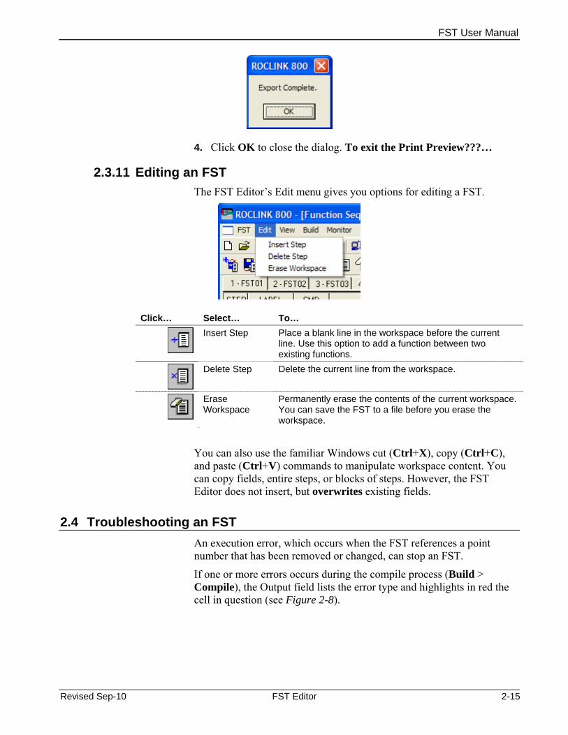
2.3.11 Editing an FST The FST Editor’s Edit menu gives you options for editing a FST.
Click… Select… To…
Insert Step Place a blank line in the workspace before the current line. Use this option to add a function between two existing functions.
Delete Step Delete the current line from the workspace.
Erase Workspace
Permanently erase the contents of the current workspace. You can save the FST to a file before you erase the workspace.
You can also use the familiar Windows cut (Ctrl+X), copy (Ctrl+C), and paste (Ctrl+V) commands to manipulate workspace content. You can copy fields, entire steps, or blocks of steps. However, the FST Editor does not insert, but overwrites existing fields.
2.4 Troubleshooting an FST An execution error, which occurs when the FST references a point number that has been removed or changed, can stop an FST.
If one or more errors occurs during the compile process (Build > Compile), the Output field lists the error type and highlights in red the cell in question (see Figure 2-8).
Revised Sep-10 FST Editor 2-15

FST User Manual
2-16 FST Editor Revised Sep-10
Figure 2-8. Compile Errors
Execution errors are caused by changes in the device configuration after the download of an FST. This may include removal of I/O or other logical points the FST uses.
In Monitor mode, the Run Flag Status (RF) indicates execution errors: RF Meaning 0 Indicates the FST is not running. 1 Indicates the FST is running.
5 Indicates the FST has shut down due to an invalid point reference (usually an out-of-place or unexpected I/O).
8 Indicates the FST Editor has initiated Trace mode. When an FST fails (as indicated by an RF value of 5), you can view the specific IP at which the FST failed.
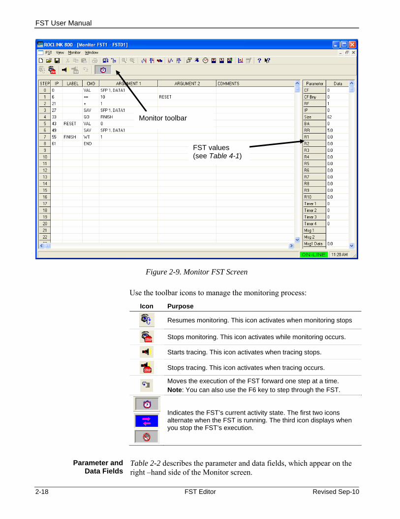
2.4.1 Monitoring an FST Monitoring an FST is an online function that enables you to watch the components of an FST change as the FST executes.
Use the FST Monitor menu to select which FST to monitor; turn Trace mode on and off; close the FST; pause or resume an FST; monitor

FST User Manual
registers, timers, miscellaneous registers, and messages; and compare flag options.
Note: Tracing an FST is another technique for troubleshooting. You active tracing from the Monitor screen. Refer to Section 2.4.2, Tracing an FST, for detailed instructions.
To start Monitor mode, either:
Select Monitor from the FST menu bar and then select an FST:
Click the Monitor icon ( )on the FST toolbar.
Note: This option starts Monitor mode only for the currently selected FST.
The Monitor FST screen displays and begins monitoring the selected FST.
Revised Sep-10 FST Editor 2-17
FST User Manual
2-18 FST Editor Revised Sep-10
Monitor toolbar
FST values (see Table 4-1)
Figure 2-9. Monitor FST Screen
Use the toolbar icons to manage the monitoring process:
Icon Purpose
Resumes monitoring. This icon activates when monitoring stops
Stops monitoring. This icon activates while monitoring occurs.
Starts tracing. This icon activates when tracing stops.
Stops tracing. This icon activates when tracing occurs.
Moves the execution of the FST forward one step at a time. Note: You can also use the F6 key to step through the FST.
Indicates the FST’s current activity state. The first two icons alternate when the FST is running. The third icon displays when you stop the FST’s execution.
Parameter and
Data Fields Table 2-2 describes the parameter and data fields, which appear on the right –hand side of the Monitor screen.

FST User Manual
Note: You can modify the content of the Data fields located on the right side of the Monitor screen. Highlight the field, type a value, and press Enter. The new value writes to the FST and is read back on the next update. This is useful when troubleshooting or debugging an FST: you can change the value stored in a register to purposely send the FST into a loop or to pass/fail a comparison.
Table 2-6. Parameter and Data Fields
Field Description CF Compare Flag, an 8-bit integer representing the
numbers 0 through 255. Often referred to as the Signal Value Discrete (SVD).
CF Bny The Compare Flag displays as both the integer value and the binary value (bit 7 to the left and bit 0 to the right).
RF Run Flag. Valid values are:
0 Indicates the FST is not running. 1 Indicates the FST is running. 5 Indicates FST has shut down due to an invalid
point reference (usually an out-of-place or unexpected I/O).
8 Indicates the FST Editor has initiated Trace mode.
When an FST fails (as indicated by an RF value of 5), you can view at which Instruction Pointer (IP) the FST failed.
IP Instruction Pointer. Indicates the storage location in the FST of the next function to be executed. One storage location is used for each byte that stores the function.
Size The number of bytes reserved for the FST program in bytes. Equivalent to the end pointer value minus the start pointer value.
Brk The delay, in 100 millisecond intervals, between the execution of successive FST Commands or functions.
RR The Results Register or accumulator, sometimes referred to as the Signal Value Analog (SVA), is a floating-point value passed between functions or FSTs.
R1 through R10 Ten floating-point registers for each FST. The floating-point registers are used for global storage, and register contents can be called into any of the FSTs configured for a device.
Revised Sep-10 FST Editor 2-19

FST User Manual
2-20 FST Editor Revised Sep-10
Field Description Timer 1 through Timer 4
Four timers. When set greater than “0”, they decrement by “1” every 100 milliseconds. A timer can be set using the Set Timer (ST) Command or by saving the RR (Results Register) directly to the timer parameter using the SAV Command. The Check Timer (CT) Command is used to compare the timer to “0”. When greater than “0”, it branches to the desired LABEL.
MSG1 Character field for storing a message. MSG2 Not used by the FST. A value can be written to
MSG2 using the FST Registers point or a ROC Display field and viewed while monitoring or tracing the FST.
MSG Data Displays any values associated with MSG1. MISC 1 through MISC 4
Single-byte registers that can be written to and the value can be used by the FST. Valid value is 0 to 255.
Table 2-7. Monitor and Trace Mode Keystrokes
Key Action Key Action ↑ Move cursor to the cell above it. End Move cursor to the right-most cell.
↓ Move cursor to the cell below it. F1 Help. Ctrl + End Display last entry in Workspace. F6 Execute current FST command.
Ctrl + Home Display beginning of Workspace. Home Move cursor to the left-most cell. Page Down Display next page of Workspace. Page Up Display previous page of Workspace.
2.4.2 Tracing an FST
Using the FST Editor’s Trace mode, you can view at which Instruction Pointer (IP) the FST failed. Print the FST to assist in troubleshooting.
Tracing an FST enables you to examine the execution of an FST one step at a time. This is very useful when debugging FSTs.
When online, the FST Editor uses a trace mechanism that gives you the ability to debug FST program logic. Trace executes the FST function indicated by the Instruction Pointer (IP), moves the IP to the next FST function to be executed, and then stops. You can then examine the results of the FST function and determine the next FST function to be executed. The location of the action depends on the nature of the command. You can trace the action to the history log, I/O value, Point Numbers, softpoint, and so on (see Figure 2-10).

FST User Manual
Revised Sep-10 FST Editor 2-21
Figure 2-10. Trace Mode
You determine the executed command by comparing the IP shown on the Monitor screen to a list of all IPs and their corresponding commands. Trace thereby verifies proper execution and sequencing of the FST functions.
Note: Before you enter Trace mode, print out an IP listing of the FST.
If you enter Trace mode from a newly compiled FST, the FST starts at the first step. If you enter Trace mode from an executing FST, the FST starts at the step being executed.
Note: When you attempt to trace an FST that contains WT, BRK, ST, or CT commands, a pause in the sequencing can occur until the command conditions are met.
Other Trace commands include: Select Monitor > Trace On to turn on Trace mode. Select Monitor > Pause to stop the FST at the current command. Select Monitor > Resume to start the FST at the current command. Select Monitor > Trace Off to turn off Trace mode. Select Monitor > Next Step to turn off Trace mode.

FST User Manual
[This page is intentionally left blank.]
2-22 FST Editor Revised Sep-10
FST User Manual
Chapter 3 – Command Library
FST commands are characterized by a name that consists of one or more characters or mathematical symbols. In the FST Editor, select the CMD field and enter a command.
You can also click the button at the right of the field to open a list of commands, the command names, and their descriptions (actions). See Table 3-1, which describes the terms RR and CF used in the command descriptions (actions).
Table 3-2 presents each command name along with a brief description (action), the arguments (ARGUMENT1 or ARGUMENT2) required, and the effect each operation has on the RR and CF. If the RR or CF is not mentioned in the operation’s explanation, then the current content is not affected and remains unchanged. In general, only logical commands affect the CF. Refer to Section 3.1.1. for detailed descriptions of each command.
Table 3-1. Command Library Conventions
Convention Description RR (in) The value or contents of the Results Register (RR), Signal Value Analog (SVA) prior to
execution of the function (command). RR (out) Output value from Results Register (RR). CF (in) The value or contents of the Compare Flag (CF), Signal Value Discrete (SVD), prior to
execution of a function (command). CF (out) The contents of the Compare Flag (CF), following execution of the function (command).
Table 3-2. Command Summary
Category Command Action Math + RR = RR + ARGUMENT1 (add) – RR = RR – ARGUMENT1 (subtract) * RR = RR * ARGUMENT1 (multiply) / RR = RR / ARGUMENT1 (divide) ** RR = RR raised to power of ARGUMENT1 ABS RR = Absolute value of RR EXP RR = “e” (2.71828) raised to power of RR INT RR = Integer value of RR LOG RR = Log (base 10) of RR LN RR = Natural Log of RR SQR RR = Square root of RR P3 RR = 3rd-order polynomial (R1, R2, R3, R4) Logical NOT SVD = NOT SVD (0 ≥ 1; > 0 ≥ 0) AND SVD = SVD AND ARGUMENT1 OR SVD = SVD OR ARGUMENT1 XOR SVD = SVD XOR ARGUMENT1 Comparison == If RR = ARGUMENT1, go to ARGUMENT2 LABEL
Revised Sep-10 Command Library 3-1

FST User Manual
3-2 Command Library Revised Sep-10
Category Command Action != If RR <> ARGUMENT1, go to ARGUMENT2 LABEL < If RR < ARGUMENT1, go to ARGUMENT2 LABEL <= If RR <= ARGUMENT1, go to ARGUMENT2 LABEL > If RR > ARGUMENT1, go to ARGUMENT2 LABEL >= If RR >= ARGUMENT1, go to ARGUMENT2 LABEL Time ST Set Timer # ARGUMENT1 to ARGUMENT2 100 mSec intervals CT If Timer # ARGUMENT1 > 0, go to LABEL ARGUMENT2 WT Suspend FST execution for ARGUMENT1 sec DWK RR = Day of Week (1=Sunday, 7=Saturday) MND RR = Minutes since midnight Control AO Set AO# ARGUMENT1 output = ARGUMENT2 EUs DO Set DO# ARGUMENT1 status = ARGUMENT2 TDO Force discrete output Recalculation Database VAL RR = Value specified in ARGUMENT1 SAV Write RR to variable specified in ARGUMENT1 RDB Read History Value into RR WDB Write RR Value to History WTM Write Current Time to History DHV1 Read Daily History Value into RR DHT1 Read Daily History Time Stamp into RR PHV1 Read Periodic History Value into RR PHT1 Read Periodic History Time Stamp into MHV1 Read Minute History Value into RR DIS1 Read Starting Daily History Index into RR DIN1 Read Number of Daily History Indexes into RR PIS1 Read Starting Periodic History Index into RR PIN1 Read Number of Periodic History Indexes into RR GTE1 Extract Time Element from Time Stamp into RR Miscellaneous GO Jump to STEP pointed to by ARGUMENT1 LABEL MSG2 MSG String #1 = ARG1; MSG Data = ARG2 MSG1 Write ARGUMENT 1 to the FST message area END End of FST...restart at beginning BRK Delay ARGUMENT1 100 mSec intervals ALM Log 10-character message and a current value EVT Log 10-character message and a current value MS21 MSG String #2 = ARG1; MSG Data #2 = ARG2
1 Valid only in the FB100-Series, FB500-Series, FB407, and ROC300-Series 2 Valid only in the ROC800-Series and DL8000
3.1.1 Command Descriptions This section provides additional detailed descriptions of each command.
Control-related Commands
Use analog output (AO), discrete output (DO), and Timed Duration Output (TDO) control-related commands to control outputs.

FST User Manual
Revised Sep-10 Command Library 3-3
Table 3-3. Control-Related Commands
Name Description Arguments Results AO Analog output. Sets the analog output
point EUs to the argument value. If the analog output is in Manual, no output is sent.
1. Output: AO Point Database Value
2. Input: Database or Constant Value
AO Output (ARG1) = ARG2 RR(out) = RR(in) SVD(out) = SVD(in)
DO Discrete output. Sets the discrete output point status to the argument value. If the discrete output is in Manual, no output is sent.
1. Output: DO Point Database Value
2. Input: Database or Constant Value
DO Output (ARG1) = ARG2 RR(out) = RR(in) SVD(out) = SVD(in)
TDO Timed duration output: Activates a DO port configured as a TDO or TDO toggle. This command requires that you write a value to the EU Value parameter prior to the DO command.
1. DO Point Database Value
DO Output(ARG1) RR(out) = RR(in) SVD(out) = SVD(in)
Note: To trigger outputs, use the corresponding output command (see Table 3-2). These commands trigger the mechanism that changes the output value.
The analog output (AO) command sends the analog value specified in ARGUMENT2 to the analog Point Number specified in ARGUMENT1. The analog value is not sent if the analog Point Number is in Manual Mode. The check for Manual Mode is included as a safety feature and permits the FST to continue operation if the device connected to the analog output is being serviced.
If a PID loop is controlling the analog output, placing the PID loop into Manual Tracking Mode allows the FST to send a value to the output parameter of the PID. For other active PID modes, the FST and PID will be in conflict.
Mathematical Commands
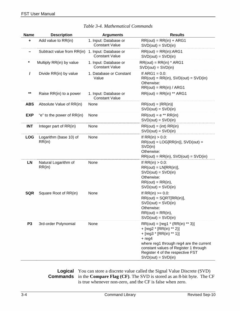
The mathematical commands provide simple arithmetic or mathematical operations. Such operations include addition (+), subtraction (–), multiplication (*), division (/), raise to power (**), absolute value (ABS), “e” raised to a power (EXP), truncate to integer (INT), base 10 logarithm (LOG), natural logarithm (LN), square root (SQR), and 3rd-order polynomial (P3).
Note: No operation occurs with the LOG, LN, power (**), and SQR commands if the Results Register is less than or equal to zero.
FST User Manual
3-4 Command Library Revised Sep-10
Table 3-4. Mathematical Commands
Name Description Arguments Results + Add value to RR(in) 1. Input: Database or
Constant Value RR(out) = RR(in) + ARG1 SVD(out) = SVD(in)
– Subtract value from RR(in) 1. Input: Database or Constant Value
RR(out) = RR(in):ARG1 SVD(out) = SVD(in)
* Multiply RR(in) by value 1. Input: Database or Constant Value
RR(out) = RR(in) * ARG1 SVD(out) = SVD(in)
/ Divide RR(in) by value 1. Database or Constant Value
If ARG1 = 0.0: RR(out) = RR(in), SVD(out) = SVD(in) Otherwise: RR(out) = RR(in) / ARG1
** Raise RR(in) to a power 1. Input: Database or Constant Value
RR(out) = RR(in) ** ARG1
ABS Absolute Value of RR(in) None RR(out) = |RR(in)| SVD(out) = SVD(in)
EXP “e” to the power of RR(in) None RR(out) = e ** RR(in) SVD(out) = SVD(in)
INT Integer part of RR(in) None RR(out) = (int) RR(in) SVD(out) = SVD(in)
LOG Logarithm (base 10) of RR(in)
None If RR(in) > 0.0: RR(out) = LOG[RR(in)], SVD(out) = SVD(in) Otherwise: RR(out) = RR(in), SVD(out) = SVD(in)
LN Natural Logarithm of RR(in)
None If RR(in) > 0.0: RR(out) = LN[RR(in)], SVD(out) = SVD(in) Otherwise: RR(out) = RR(in), SVD(out) = SVD(in)
SQR Square Root of RR(in) None If RR(in) >= 0.0: RR(out) = SQRT[RR(in)], SVD(out) = SVD(in) Otherwise: RR(out) = RR(in), SVD(out) = SVD(in)
P3 3rd-order Polynomial None RR(out) = [reg1 * (RR(in) ** 3)] + [reg2 * [RR(in) ** 2)] + [reg3 * [RR(in) ** 1)] + reg4 where reg1 through reg4 are the current constant values of Register 1 through Register 4 of the respective FST SVD(out) = SVD(in)
Logical Commands
You can store a discrete value called the Signal Value Discrete (SVD) in the Compare Flag (CF). The SVD is stored as an 8-bit byte. The CF is true whenever non-zero, and the CF is false when zero.

FST User Manual
Revised Sep-10 Command Library 3-5
Logical commands operate upon the Compare Flag (CF). Prior to execution of a logical command, the CF must be loaded with an 8-bit value by using the SAV command.
The bit-wise logical commands (AND, OR, NOT, and XOR) apply Boolean operations on two 8-bit integers, bit-by-bit. The two 8-bit integers are the CF and the value defined by ARGUMENT1 of the logical command. Note that this value is then converted by the software into an 8-bit unsigned integer. This value is used as a binary number 8 bits long as described next.
Each bit is weighted as a power of two, and the bit position determines which power of two. The bit, either 0 or 1, is multiplied by the respective bit weight. The resulting binary number is read from right to left, with the right-most bit representing bit 0, and the left-most bit representing bit 7.
For example, the integer 42 is equivalent to the binary number 00101010 as shown next, where bit 0 is the right-most bit:
Bit Binary # * Weight = Bit 7 = 0 * 27 = 0 * 128 = 0 Bit 6 = 0 * 26 = 0 * 64 = 0 Bit 5 = 1 * 25 = 1 * 32 = 32 Bit 4 = 0 * 24 = 0 * 16 = 0 Bit 3 = 1 * 23 = 1 * 8 = 8 Bit 2 = 0 * 22 = 0 * 4 = 0 Bit 1 = 1 * 21 = 1 * 2 = 2 Bit 0 = 0 * 20 = 0 * 1 = 0
Total = 42
Table 3-5. Logical Commands
Name Description Arguments Results NOT Logical NOT of SVD(in) None If SVD(in) > 0, SVD(out) = 0
Otherwise: SVD(out) = 1 RR(out) = RR(in)
AND Logical AND ARG1 with SVD(in) 1. Input: Database or Constant Value
RR(out) = RR(in),
RR(out) = RR(in), OR Logical OR ARG1 with SVD(in) 1. Input: Database or Constant Value SVD(out) = [SVD(in) OR ARG1]
RR(out) = RR(in), XOR Logical XOR ARG1 with SVD(in) 1. Input: Database or Constant Value SVD(out) = [SVD(in) XOR ARG1]
Comparison Commands
Use comparison commands to compare values. Comparison commands conditionally compare two values, and branch to a different sequence of commands if the comparison is determined to be true.

FST User Manual
3-6 Command Library Revised Sep-10
Otherwise, if the comparison is determined to be false, no branching occurs and the next command in sequence is executed. Comparison commands test values for equivalence (==), non-equivalence (!=), less than (<), less than or equal to (<=), greater than (>) , and greater than or equal to (>=).
Table 3-6. Comparison Commands
Name Description Arguments Results == Test If RR(in) equals ARG1.
Note that this command performs in a bit-wise fashion, so two floating Point Numbers displayed as equal may not match.
1. Input: Database or Constant Value 2. LABEL
If RR(in) = ARG1, Goto ARG2 Otherwise: continue to next command SVD(out) = SVD(in)
!= Test If RR(in) Not Equal to ARG1.
1. Input: Database or Constant Value 2. LABEL
If RR(in) != ARG1, Goto ARG2 Otherwise: continue to next command RR(out) = RR(in) SVD(out) = SVD(in)
< Test If RR(in) less than ARG1. 1. Input: Database or Constant Value 2. LABEL
If RR(in) < ARG1, Go to ARG2 Otherwise: continue to next command RR(out) = RR(in) SVD(out) = SVD(in)
<= Test If RR(in) less than or equal to ARG1.
1. Input: Database or Constant Value 2. LABEL
If RR(in) <= ARG1, Go to ARG2 Otherwise: continue to next command RR(out) = RR(in) SVD(out) = SVD(in)
> Test If RR(in) greater than ARG1.
1. Input: Database or Constant Value 2. LABEL
If RR(in) > ARG1, Go to ARG2 Otherwise: continue to next command RR(out) = RR(in) SVD(out) = SVD(in)
>= Test if RR(in) greater than or equal to ARG1.
1. Input: Database or Constant Value 2. LABEL
If RR(in) >= ARG1, go to ARG2 Otherwise: continue to next command RR(out) = RR(in) SVD(out) = SVD(in)
Time-Related Commands
Use time-related commands (FST Timers) to implement simple time-related operations, such as setting timers, checking timers, determining if timers have elapsed, wait time before continuing, and imposing a delay upon each command executed.
Use timers to branch the FST to a specific label after a specified period of time following an action. Each FST can support up to four timers and

FST User Manual
Revised Sep-10 Command Library 3-7
each timer has a time interval of 100 milliseconds. Each FST timer decreases by 1 interval if the timer value is greater than 0.
Command Description Set Timer (ST) The ST command sets any one of the four available
Timers for any of the available FSTs. ARGUMENT1 specifies the number of the timer to set and ARGUMENT2 specifies the number of intervals to which the timer is set.
Check Timer (CT) When executing a loop repeatedly in an FST, we recommend that you include a check timer (CT) command so the loop executes only once every time interval. This prevents the loop from executing several times within the allotted task period, eliminating unnecessary calculations that could deprive time from other tasks.
Wait (WT) The Wait (WT) command imposes a delay, entered in seconds and tenths of seconds, before executing the next command. For example, entering a value of 0.1 implies a 100-millisecond delay and a value of 1.0 implies a one-second delay.
Day of Week (DWK) and Minutes Since Midnight (MND)
These commands are written to the Results Register. For DWK, 1=Sunday through 7=Saturday.
Table 3-7. Time-Related Commands
Name Description Arguments Results ST Set Timer for specified FST with
value in 100 mSec intervals. 1. Output: FST Point Database Value 2. Input: Database or
Constant Value
FST Timer (ARG1) = ARG2 RR(out) = RR(in) SVD(out) = SVD(in)
CT Check Timer for specified FST with value in 100 mSec intervals.
1. Input: FST Point Database Value 2. LABEL
If FST Timer (ARG1) = 0, continue to next command. Otherwise, Goto ARG2. RR(out) = RR(in) SVD(out) = SVD(in)
WT Wait – suspend FST until specified number of seconds (ARG1) have elapsed. The number of seconds can be from 0.1 to 999,999.
1. Input: Database or Constant Value
Delay ARG1 seconds RR(out) = RR(in) SVD(out) = SVD(in)
DWK Day of Week – sets RR (out) to the day of the week (1=Sunday, 7=Saturday). Note: The DWK function requires
that you correctly set the real-time clock.
None RR(out) = Day of Week SVD(out) = SVD(in)
MND Minutes Since Midnight – sets RR (out) to the number of minutes past midnight.
None RR(out) = Minutes SVD(out) = SVD(in)

FST User Manual
3-8 Command Library Revised Sep-10
Miscellaneous Commands
Use the miscellaneous commands to move around FSTs and end FSTs. Miscellaneous commands provide operations, such as an unconditional go to (GO), message to local display panel (MSG), alarms (ALM), and event (EVT) generation, end of the FST (END), and delay (BRK).
Command Description GO Executes an unconditional branch to the label
specified in ARGUMENT1. Branching can direct the FST to a step before or after the current step.
MSG Provides a 30-character message and value that appears on the local display panel.
MS2 Provides an additional 30-character message and value that appears on the local display panel.
BRK Imposes a delay (break period), in 100-millisecond intervals, before executing the next command. Once you set the break period to a non-zero value, a delay in 100-millisecond or 1 second intervals occurs between the executions of each subsequent command.
END Completes execution of the FST and waits for the next FST execution cycle before returning to the first STEP of the FST. The END command can only be used once in an FST. If omitted, End is appended to the FST by the FST Editor at compile time following the first empty Command field.
ALM Logs a 10-character message and the current value of the selected parameter to the Alarm log.
EVT Logs a 10-character message and the current value of the selected parameter to the Events log.
Table 3-8. Miscellaneous Commands
Name Description Arguments Results GO Go to specified LABEL. 1. LABEL Goto ARG1
RR(out) = RR(in) SVD(out) = SVD(in)
BRK Break delays execution of each command after this one for the number of 100 millisecond intervals defined by ARGUMENT1.
1. Input: Database or Constant Value
FST break time = ARG1 RR(out) = RR(in) SVD(out) = SVD(in)
END End of FST returns to first command.
None Execute FST starting with first command. RR(out) = RR(in) SVD(out) = SVD(in)

FST User Manual
Revised Sep-10 Command Library 3-9
Name Description Arguments Results MSG LCD Message sends message
(ARGUMENT1) and value (ARGUMENT2) to local display panel. One 30 character message can be sent by each FST as shown next: xxxxxxxxxxxxxxxxxx xxxxxxxx ARG2 VAL yyyyyyyy zzzzz.zz SCAN NEXT PREV MENU xxxx ...message yyyy ...FST Tag name zzzz ...ARGUMENT2 value
1. Input: Message 2. Input: Database or Constant Value
FST Message String(ARG1) FST Message Value(ARG2) RR(out) = RR(in) SVD(out) = SVD(in)
ALM Log Alarm records message (ARGUMENT1) and value (ARGUMENT2) in the Alarm Log. Only the first 10 characters of the 30 character messages are used.
1 .Input: Message 2. Input: Database or Constant Value
Log Alarm(ARG1, ARG2) RR(out) = RR(in) SVD(out) = SVD(in)
EVT Log Event records message (ARGUMENT1) and value (ARGUMENT2) in the Event Log. Only the first 10 characters of the 30 character message are used.
1. Input: Message 2. Input: Database or Constant Value
Log Event(ARG1,ARG2) RR(out) = RR(in) SVD(out) = SVD(in)
Note: The ALM and EVT functions can quickly overfill the allotted log space of alarms and events. It is important to assure that these two functions do not operate continuously.
Database Commands
Database commands provide access to the configuration and historical databases. Operations include reading and writing configuration parameters and reading, writing, storing values from historical databases, and time stamping values to a History Point.
Command Description VAL Loads the Results Register (RR) with the value
defined in ARGUMENT1. ARGUMENT1 can be a constant or any database parameter available to the FST. The system converts the value defined in ARGUMENT1 to floating point data type and writes it to the Results Register.
SAV Writes the Results Register (RR) value to any database parameter available to the FST as defined in ARGUMENT1.
WDB, WTM, and RDB These historical database commands, Write to Historical Database (WDB), Write Time to Historical Database (WTM), and Read Historical Database (RDB), allow you to establish a non-periodic history database (one that has no specific time interval), a periodic history database (one that has a specific

FST User Manual
3-10 Command Library Revised Sep-10
Command Description time interval), or a storage array for data (similar to a softpoint). For the FST historical database commands to work, you have to correctly configure a history point as either an FST Time Archive Type or an FST Data Archive Type. Refer to Section 3.1.2, Defining a FST History Point. The FST for a history point uses one of the historical database commands and two arguments. ARGUMENT1 contains the history database point number. ARGUMENT1 can be a constant or a parameter with a value between 1 through 87.
ARGUMENT2 Provides an index or pointer to the history storage array. The history storage array holds entries taken at either set intervals (typically daily, hourly, and each minute) or user-configurable intervals. For information on the intervals and number of entries, refer to the history database specifications instruction manual. ARGUMENT2 should be a soft point or an FST register. The history point ARGUMENT 1 defines logs to the index location ARGUMENT 2 defines.
Table 3-9. Database Commands
Name Description Arguments Results VAL Load RR sets the RR(out) to the argument
value. 1. Input: Database
or Constant Value
RR(out) = ARG1 SVD(out) = SVD(in)
SAV Store RR sets the argument to the RR(in). 1. Output: Database Value
ARG1 = RR(in) RR(out) = RR(in) SVD(out) = SVD(in)
RDB Read Historical Database sets the RR(out) to the historical database value of the specified database point (ARGUMENT1) and the specified pointer (ARGUMENT2) to the historical database value. Applies to historical database points defined for the FST only. If ARGUMENT2* is a floating database value (such as FST1, R8), the command increments ARGUMENT2 to the next historical database value and sets it to 0 when the number of archived historical periods are exceeded. Otherwise, no effect occurs to ARGUMENT2. Note: Each ARGUMENT2 must be
unique.
1. Input: Database or Constant Value
2. Output: Database or Constant Value
For FST History Point: RR(out) = History Value(ARG1,ARG2)For floating database value ARG2: If ARG1 >= No. of archived periods (ARG1), then ARG2 = 0 Otherwise, ARG2 = ARG2 + 1 For all other cases: RR(out) = RR(in) SVD(out) = SVD(in)

FST User Manual
Revised Sep-10 Command Library 3-11
Name Description Arguments Results WDB Write To Historical Database sets the
RR(in) to the value of the database point (ARGUMENT1) and the pointer (ARGUMENT2). Applies to historical database points defined for the FST only. If ARGUMENT2* is a floating database value (such as FST1, R8), the command increments ARGUMENT2 to the next historical database value and sets it to 0 when the number of archived historical periods are exceeded. Otherwise, no effect occurs to ARGUMENT2. Note: Each ARGUMENT2 must be
unique.
1. Output: Database or Constant Value
2. Output: Database or Constant Value
For FST History Point: History Value (ARG1, ARG2) = RR(in). For floating database value ARG2: If ARG2 >= No. of archived periods (ARG1), then ARG2 = 0. Otherwise, ARG2 = ARG2 + 1. For all other cases: RR(out) = RR(in) SVD(out) = SVD(in)
WTM Write Time To Historical Database sets the value of the database point (ARGUMENT1) and the pointer (ARGUMENT2) to the historical database time string with either minutes or seconds resolution. The time format for minute's resolution is [min,hr,day,mon] and for seconds resolution is [sec,min,hr,day]. Applies to historical database points defined for the FST only. If ARGUMENT2* is a floating database value (such as FST1, R8), the command increments ARGUMENT2 to the next historical database value and sets it to 0 when the number of archived historical periods are exceeded. Otherwise, no effect occurs to ARGUMENT2. Note: Each ARGUMENT2 must be
unique.
1. Output: Database or Constant Value
2. Output: Database or Constant Value
For FST History Point: If minute resolution, then History Value (ARG1, ARG2 = minute format. Otherwise: History Value (ARG1,ARG2) = second format. For floating database value ARG2: If ARG2 >= number of archived periods (ARG1), then ARG2 = 0. Otherwise: ARG2 = ARG2 + 1. For all other cases: RR(out) = RR(in) SVD(out) = SVD(in)
3.1.2 Defining a FST History Point When defining history database points for WDB, WTM, and RDB, you must define at least one history point as an FST Time type (minute or second) to provide a time stamp for the values logged. The time stamps represent what time each portion of the accumulated data was logged.
To define an FST history point:
1. Select Configure > History Points.
2. Select the desired History Point.
3. Click the Archive Type TLP button and select FST Time or FST Data.
4. Click the Archive Point TLP button and select any TLP, such as FST Register 2 to contain the data or time stamp. The Archive Point selection is ignored by the FST.
5. Click OK.
FST User Manual
3-12 Command Library Revised Sep-10
Historical Commands
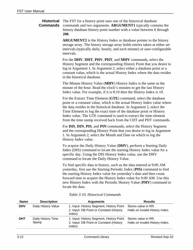
The FST for a history point uses one of the historical database commands and two arguments. ARGUMENT1 typically contains the history database history point number with a value between 1 through 200.
ARGUMENT2 is the History Index or database pointer to the history storage array. The history storage array holds entries taken at either set intervals (typically daily, hourly, and each minute) or user-configurable intervals.
For the DHV, DHT, PHV, PHT, and MHV commands, select the History Segment and the corresponding History Point that you desire to log in Argument 1. In Argument 2, select either a database point or a constant value, which is the actual History Index where the data resides in the historical database.
The Minute History Value (MHV) History Index is the same as the minute of the hour. Read the clock’s minutes to get the last History Index value. For example, if it is 8:10 then the History Index is 10.
For the Extract Time Element (GTE) command, select the database point or a constant value, which is the actual History Index value where the data resides in the historical database. In Argument 2, select the Time Element to log the exact time of the database point or History Index value. The GTE command is used to extract the time element from the time stamp received back from the CHT and PHT commands.
For DIS, DIN, PIS, and PIN commands, select the History Segment and the corresponding History Point that you desire to log in Argument 1. In Argument 2, select the Month and Date on which to log the History Index value.
To acquire the Daily History Value (DHV), perform a Starting Daily Index (DIS) command to locate the starting History Index value for a specific day. Using the DIS History Index value, use the DHV command to locate the Daily History Value.
To find specific data in history, such as the data entered at 9:00 AM yesterday, first use the Starting Periodic Index (PIS) command to find the starting History Index value for yesterday’s date and then count forward nine to acquire the History Index value for 9:00 AM. Use this new History Index with the Periodic History Value (PHV) command to locate the data.
Table 3-10. Historical Commands
Name Description Arguments Results DHV Daily History Value 1. Input: History Segment, History Point
2. Input: DB Point or Constant (History Index)
Stores value in RR. Halts on invalid History Index.
DHT Daily History Time Stamp
1. Input: History Segment, History Point2. Input: DB Point or Constant (History Index)
Stores value in RR. Halts on invalid History Index.
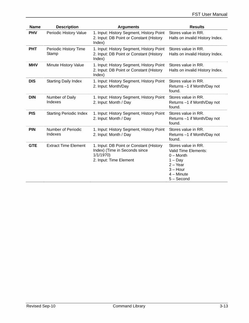
FST User Manual
Revised Sep-10 Command Library 3-13
Name Description Arguments Results PHV Periodic History Value 1. Input: History Segment, History Point
2. Input: DB Point or Constant (History Index)
Stores value in RR. Halts on invalid History Index.
PHT Periodic History Time Stamp
1. Input: History Segment, History Point2. Input: DB Point or Constant (History Index)
Stores value in RR. Halts on invalid History Index.
MHV Minute History Value 1. Input: History Segment, History Point2. Input: DB Point or Constant (History Index)
Stores value in RR. Halts on invalid History Index.
DIS Starting Daily Index 1. Input: History Segment, History Point2. Input: Month/Day
Stores value in RR. Returns –1 if Month/Day not found.
DIN Number of Daily Indexes
1. Input: History Segment, History Point2. Input: Month / Day
Stores value in RR. Returns –1 if Month/Day not found.
PIS Starting Periodic Index 1. Input: History Segment, History Point2. Input: Month / Day
Stores value in RR. Returns –1 if Month/Day not found.
PIN Number of Periodic Indexes
1. Input: History Segment, History Point2. Input: Month / Day
Stores value in RR. Returns –1 if Month/Day not found.
GTE Extract Time Element 1. Input: DB Point or Constant (History Index) (Time in Seconds since 1/1/1970) 2. Input: Time Element
Stores value in RR. Valid Time Elements: 0 – Month 1 – Day 2 – Year 3 – Hour 4 – Minute 5 – Second

FST User Manual
3-14 Command Library Revised Sep-10
[This page is intentionally left blank.]
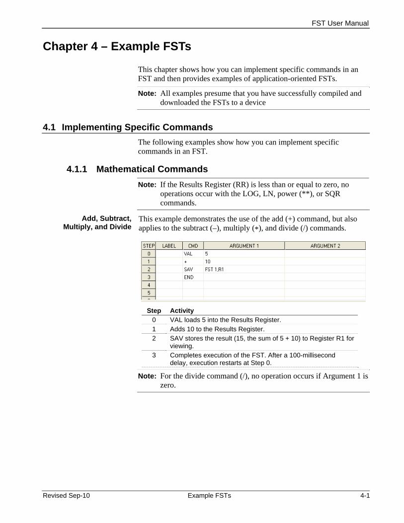
FST User Manual
Chapter 4 – Example FSTs
This chapter shows how you can implement specific commands in an FST and then provides examples of application-oriented FSTs.
Note: All examples presume that you have successfully compiled and downloaded the FSTs to a device
4.1 Implementing Specific Commands The following examples show how you can implement specific commands in an FST.
4.1.1 Mathematical Commands Note: If the Results Register (RR) is less than or equal to zero, no
operations occur with the LOG, LN, power (**), or SQR commands.
Add, Subtract, Multiply, and Divide
This example demonstrates the use of the add (+) command, but also applies to the subtract (–), multiply (*), and divide (/) commands.
Step Activity
0 VAL loads 5 into the Results Register. 1 Adds 10 to the Results Register. 2 SAV stores the result (15, the sum of 5 + 10) to Register R1 for
viewing. 3 Completes execution of the FST. After a 100-millisecond
delay, execution restarts at Step 0.
Note: For the divide command (/), no operation occurs if Argument 1 is zero.
Revised Sep-10 Example FSTs 4-1

FST User Manual
Power and Exponent
This example demonstrates the use of the power (**) command.
Step Activity
0 VAL loads the value in Register R1 into the Results Register. 1 Raises the value in the Results Register to the power (**) of
Argument 1, which is 10. 2 SAV stores the value in the Results Register to Register R2 for
viewing. 3 Completes execution of the FST. After a 100-millisecond
delay, execution restarts at Step 0.
Note: If the Results Register (RR) is less than or equal to zero, no operation occurs with the LOG, LN, ** (power), or SQR commands.
This example demonstrates the use of the exponent (EXP) command.
Step Activity
0 VAL loads the value of Register R1 into the Results Register. 1 Updates the value in the Results Register with the value of “e”
(2.718). 2 SAV stores the value in the Results Register to Register R2 for
viewing. 3 Completes execution of the FST. After a 100-millisecond
delay, execution restarts at Step 0.
Absolute Value, Integer, Logarithm, and
Square Root
This example demonstrates the use of the absolute value (ABS) command, but also applies to the integer (INT), base 10 logarithm (LOG), natural logarithm (LN), and square root (SQR) commands.
Note: If the Results Register (RR) is less than or equal to zero, no operation occurs with the LOG, LN, ** (power), or SQR commands.
4-2 Example FSTs Revised Sep-10

FST User Manual
Step Activity
0 VAL loads the value of Register R1 into the Results Register. 1 Updates the value in the Results Register with the absolute
value. 2 SAV stores the value in the Results Register to Register R2 for
viewing. 3 Completes execution of the FST. After a 100-millisecond
delay, execution restarts at Step 0.
Polynomials This example demonstrates the use of the polynomial (P3) command. This command performs a 3rd-order polynomial calculation of the following form:
Y = AX3 + BX2 + CX + D Where: X = Results Register before the polynomial calculation. Y = Results Register after the polynomial calculation. A, B, C, and D = Coefficients for the polynomial calculation.
In this example, the 3rd-order polynomial calculates the decimal equivalent of a 4-bit binary number. The coefficients from the above equation (A, B, C, and D) represent the individual bit values (0 or 1) of the 4-bit binary number. You enter the coefficients manually as either 0 or 1 into FST Registers R1 through R4. The decimal equivalent of the 4-bit binary number displays in FST Register R5.
Step Activity
0 VAL loads the value for A into the Results Register. 1 SAV stores the value from Step 0 into R1 for use in the
calculation. 2 VAL loads the value for B into the Results Register.
Revised Sep-10 Example FSTs 4-3

FST User Manual
Step Activity 3 SAV stores the value from Step 2 in R2 for use in the
calculation. 4 VAL loads the value for C into the Results Register. 5 SAV stores the value from Step 4 into R3 for use in the
calculation. 6 VAL loads the value for D into the Results Register. 7 SAVE stores the value from Step 6 into R4 for use in the
calculation. 8 VAL loads the value for E into the Results Register. 9 P3 calculates the third-order polynominal.
10 SAV stores the result from Step 9 to Softpoint 1 Data 6. 11 Completes execution of the FST..
4.1.2 Logical Commands The following example demonstrates the use of the OR command to set the Disabled/Remote SP Mode bit of a PID point to Remote SP, but the principles apply to the use of the other logical commands.
Step Activity
0 VAL loads the Results Register (SVA) with the value of the PID mode parameter from PID point number 1.
1 SAV stores the value of the PID mode parameter (now contained in the Results Register) into the Compare Flag parameter of FST1. The contents of the Results Register and the Compare Flag (CF) are not the same. Because there is no single command to directly load a value into the Compare Flag, the VAL and SAV commands are used. Likewise, it takes both commands to save a value from the Compare Flag (shown in Steps 3 and 4).
2 OR takes the logical “OR” between the Compare Flag and the value of the integer 1 (binary 0001) and writes the result into the Compare Flag, overwriting the contents (the previous PID mode value). The OR operation effectively sets the right-most bit (Bit 0) to a logical 1, leaving the other bits unaffected. Because Bit 0 of the PID mode parameter controls the Disable/Remote SP Mode, only this bit is set to 1, which the system interprets as the Remote SP mode.
3 VAL loads the contents of the Compare Flag back into the Results Register.
4-4 Example FSTs Revised Sep-10

FST User Manual
Step Activity 4 SAV copies the value in the Results Register into the PID
mode parameter (setting the Disabled/Remote SP to Auto). 5 END completes execution of the FST. After a 100-millisecond
delay, execution restarts at Step 0.
4.1.3 Comparison Commands This example demonstrates the use of the equal command, but the principles also apply to the not equal (!=), less than (<), less than or equal to (<=), greater than (>), and greater than or equal to (>=) commands.
The example compares a user-entered value R1 to the value 10 and the logical result true (1) or false (0) is reflected in R5.
Step Activity
0 VAL reads the contents of Register R1 and load the value in the Results Register.
1 Compares (= =) the value in the Results Register to the value 10. If the value in the Results Register equals 10, then branch to the label (TRUE) in Argument 2. In this case, the branch would go to Step 4 and continue execution. If the value in the Results Register is not 10, execution continues with Step 2.
2 If the comparison in Step 1 is FALSO, VAL loads the Results Register with value 0 (FALSE) to be saved in Step 5.
3 Moves the FST to the label SAVE (Step 5). This step branches past Step 4, which is executed only for TRUE comparisons.
4 If the comparison in Step 1 is TRUE, VAL loads the Results Register with the value 1 (TRUE) to be saved in Step 5.
5 SAV stores the value in the Results Register to Register R5. 6 END completes execution of the FST. After a 100-millisecond
delay, execution restarts at Step 0.
4.1.4 Time-Related Commands The following example demonstrates the use of timers. In this example, this portion of an FST opens a valve allowing a fluid to flow. After an elapsed period, the valve closes when the flow falls below a pre-determined level.
Revised Sep-10 Example FSTs 4-5

FST User Manual
Step Activity
0 AO opens the control valve to 100 percent flow. 1 ST sets Timer 1 (TMR1) for 600 100-mSec periods (1 minute).
The flow rate should be at least 25 of maximum after 1 minute. 2 WT waits 5 seconds. This delay helps control the rate of the
FST’s execution, freeing time for other tasks. Not using a delay can cause unnecessary repetitive executions. This step also has a label (AGAIN).
3 VAL reads the instantaneous substance flow rate as measured by the analog input (module 4, channel 2).
4 The Greater Than Compare command (>) compares the measured flow rate to 25 percent.
5 The flow is expected to be at least 25 percent after 1 minute. If the Check Timer (CT) has not expired and flow is less than 25 percent, the FST remains in the loop either until the timer expires or flow reaches 25 percent. If the 1-minute span expires and flow has not reached 25 percent, the control valve closes.
6 AO closes the control valve to 0 percent flow. 7 After the control valve closes, wait 1 hour (3600 seconds)
before attempting to re-open the valve. 8 GO restarts the FST at Step 0 (START).
33 A step that monitors the flowing conditions determining shutdown.
54 END completes execution of the FST. After a 100-millisecond delay, execution restarts at Step 0.
Monitor flowing conditions determining shutdown
4-6 Example FSTs Revised Sep-10

FST User Manual
FST Timers The FST Timer is an unsigned long data type (32 bit integer) and
supports numbers up to 4,294,967,295. However, when writing an FST that sets the timer (as shown in the following example), limit the number to no more than 8,388,608. Any number larger than this value can lose significance when the FST Editor converts it to a single precision number.
4.1.5 Control-Related Commands Analog Output Following is an example of an Analog Output (AO) control command in
an FST.
Step Activity
0 VAL loads the Results Register with the value 100. 1 GO moves the FST to the step labeled OUTPUT (Step 8). 4 VAL loads the Results Register with the value 0. 5 GO moves the FST to the step labeled OUTPUT (Step 8). 8 AO operates the control (or equivalent device) to the value
indicated by Argument 1 (here, the value of the Results Register).
9 END completes execution of the FST. After a 100-millisecond delay, execution restarts at Step 0.
Note: The FB407 and ROC300-Series devices must use the AO, DO,
and TDO commands to drive outputs from an FST. SAV and other commands doe not affect the output.
Revised Sep-10 Example FSTs 4-7

FST User Manual
Discrete Output Following is an example of a Discrete Output (DO) control command in an FST.
Step Activity
0 DO activates output to the ON (or equivalent) state. 10 DO activates output to the OFF (or equivalent) state. 20 DO activates output to the ON state. 21 WT delays 2 seconds. This allows the output to be on for a
minimum of 2 seconds. 22 DO activates output to the OFF state.
Steps 20, 21, and 22 are equivalent to a Timed Duration Output pulse with a duration of 2 seconds.
Note: The FB407 and ROC300-Series devices must use the AO, DO, and TDO commands to drive outputs from an FST. SAV and other commands doe not affect the output.
Timed Duration Output
Following is an example of a Timed Duration Output (TDO) control command in an FST.
Step Activity
0 VAL loads the Results Register with the value 2 (percent or seconds output, depending on the configuration).
1 SAV stores the value in the Results Register to the EU parameter for the DO point number 1.
2 TDO pulses the DO point number 2 for 2 (percent or seconds). 3 END completes execution of the FST. After a 100-millisecond
delay, execution restarts at Step 0. Note: The FB407 and ROC300-Series devices must use the AO, DO,
and TDO commands to drive outputs from an FST. SAV and other commands doe not affect the output.
4-8 Example FSTs Revised Sep-10

FST User Manual
4.1.6 Database Commands Database commands provide access to the device’s configuration and historical databases. Operations include reading and writing configuration parameters; and reading, writing, and time stamping values to a history point.
The following examples show the use of the value (VAL) and save (SAV) commands. In this example, the values from Register 1 of FST 1 and the user-defined value 5 are saved to the Results Register. The SAV command then saves the value from the Results Register to Register 2 of FST 1.
The following example shows the RR and R1 values before and after the WDB command executes.
Before execution, RR = 50.00 and R1= 25 (floating point value)
After execution, the system sets the History database segment 1 point 9 to 50.00 and the R1 to 26. This increments the history pointer for the next value.
4.1.7 Miscellaneous Commands The following example demonstrates the use of the Message (MSG) and GO commands. Enter a value in Register R1 that is compared to the value 10. Depending upon the result of the comparison, a message is sent to the display panel indicating that the value in R1 is either less than, greater than, or equal to 10. The value of R1 also displays.
Step Activity
Revised Sep-10 Example FSTs 4-9

FST User Manual
Step Activity 0 VAL loads the Results Register with the R1. 1 If the Results Register value equals 10, branch to the step
labeled EQUAL (Step 5). Otherwise, continue to Step 3. 2 If the Results Register value is less than 10, branch to the step
labeled LESS (Step 7). 3 If the value in the Results Register is greater than (>) 10, send
the message (MSG) in Argument 1 and the value (R1) in Argument 2 to the local display panel.
4 GO moves the FST to the step labeled FINISH (Step 8), which ends the FST.
5 If the value in the Results Register equals 10, send the message (MSG) in Argument 1 and the value in Argument 2 to the local display panel.
6 GO moves the FST to the step labeled FINISH (Step 8), which ends the FST.
7 If the value in the Results Register is less than 10, send the message (MSG) in Argument 1 and the value in Argument 2 to the local display panel.
8 END completes execution of the FST. After a 100-millisecond delay, execution restarts at Step 0.
4.2 Application-based Examples This section provides examples of application-focused FSTs.
4.2.1 Writing Data to a History Point This example defines two historical database points to demonstrate how to use an FST to create a 7-minute-based “history log.” The first part of the process defines historical database points; the second part creates the FST.
1. Select Configure > History Segments. The History Segments screen displays.
2. Enter 10 in the Number of Points field for Segment 01 to define 10 points of history. Click Apply to save your changes and click OK to close the screen.
3. Select Configure > History Points. The History Segment Point Configuration screen displays.
4. Click the Seg 1 tab.
5. Click in the Archive Type field for Point 9. Select FST Data from the drop-down menu.
6. Click in the Archive Point field for Point 9 and click the … button. On the Select TLP screen that displays select FST Parameters as the Point Type, FST 1 as the Logical Number, and 1 Result Register as the Parameter.
7. Click OK to close the Select TLP screen.
4-10 Example FSTs Revised Sep-10

FST User Manual
8. Click in the Archive Type field for Point 10. Select FST Time from the drop-down menu.
9. Click in the Archive Point field for Point 10 and click the … button. On the Select TLP screen that displays select FST Parameters as the Point Type, FST 1 as the Logical Number, and 2 Register 1 as the Parameter.
10. Click OK to close the Select TLP screen. The History Segment Point Configuration screen should look like Figure 4-1:
Figure 4-1. History Segment Point Configuration
Defining a history database history point as either an FST data or FST time archival point allows the WDB, WTM, and RDB commands to work. You must also supply a history point number (in this example, 9 and 10) as ARGUMENT1 for these commands. Although points 9 and 10 are used in this example, you could use any available history database points.
Note: The point and parameter definitions for this history point only provide descriptive text used when you select history points for viewing.
With the history database points defined, we can build the FST.
11. Click Apply to save your changes and click OK to close the History Segment Point Configuration screen.
12. Select Utilities > FST Editor. The FST Editor screen displays.
13. Complete the FST Editor screen as shown in Figure 4-2.
Revised Sep-10 Example FSTs 4-11
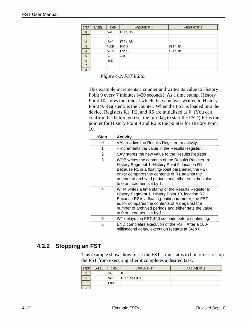
FST User Manual
Figure 4-2. FST Editor
This example increments a counter and writes its value to History Point 9 every 7 minutes (420 seconds). As a time stamp, History Point 10 stores the time at which the value was written to History Point 9. Register 5 is the counter. When the FST is loaded into the device, Registers R1, R2, and R5 are initialized as 0. (You can confirm this before you set the run flag to start the FST.) R1 is the pointer for History Point 9 and R2 is the pointer for History Point 10.
Step Activity 0 VAL readies the Results Register for activity. 1 + increments the value in the Results Register. 2 SAV stores the new value to the Results Register. 3 WDB writes the contents of the Results Register to
History Segment 1, History Point 9, location R1. Because R1 is a floating-point parameter, the FST editor compares the contents of R1 against the number of archived periods and either sets the value to 0 or increments it by 1.
4 WTM writes a time stamp of the Results Register to History Segment 1, History Point 10, location R2. Because R2 is a floating-point parameter, the FST editor compares the contents of R2 against the number of archived periods and either sets the value to 0 or increments it by 1.
5 WT delays the FST 420 seconds before continuing. 6 END completes execution of the FST. After a 100-
millisecond delay, execution restarts at Step 0.
4.2.2 Stopping an FST This example shows how to set the FST’s run status to 0 in order to stop the FST from executing after it completes a desired task.
4-12 Example FSTs Revised Sep-10

FST User Manual
Step Activity 0 VAL loads the Results Register with the value 0. 1 SAV stores the value in the Results Register to the
FST Run Status. 2 END completes execution of the FST.
Note: In this case, the FST does not automatically restart because STEP 0 halts execution of the FST.
4.2.3 Cycling an FST on a Periodic Basis This example sets an FST to run on a 10-second cycle. It uses a timer to determine how much, if any, of the 10 seconds remain after the FST executes. The timer indicates the amount of time required to wait before the cycle is repeated.
Step Activity
0 Set Timer (ST) specified in Argument 1 to the number of 100-millisecond intervals specified in Argument 2. Note: Steps 1-3, omitted from this example,
represent the steps you want to recycle every 10 seconds.
4 VAL reads the timer to see if any time from the cycle remains. ROCLINK 800 uses this value to calculate the amount of time that must be delayed before the cycle can be repeated. If the timer has expired (0), then the FST did not complete within 10 seconds. If the timer has not expired, then a delay is required before the FST can repeat the cycle. To calculate the necessary delay in seconds, multiply the Timer by 0.1.
5 * (multiply) the value by 0.1. 6 Wait (WT) 7 END completes execution of the FST. After a 100-
millisecond delay, execution restarts at Step 0.
4.2.4 Calculating an Approximate Execution Rate This example uses a portion of an FST to determine the average time required to execute the FST. Again, a timer determines the number of 100-millisecond intervals that have elapsed while a sequence of functions executes.
Revised Sep-10 Example FSTs 4-13

FST User Manual
Note: ROCLINK 800 can perform the FST execution at the same time as other tasks.
Step Activity
0 Set Timer (ST) sets the timer specified in Argument 1 to the number of 100-millisecond intervals specified in Argument 2. Note: Steps 1-19, omitted from this example,
represent any FST steps. 20 VAL reads the timer to establish the reference time for
the beginning of the sequence. 21 SAV stores the value of the timer to Register R6.
Note: Steps 22-39, omitted from this example,
represent any FST steps.
40 VAL reads the timer at the end of the sequence. 41 SAV stores the value of the timer to Register R7.
To calculate the execution rate, take the difference between register values R7 and R6 and multiply that result by 0.1 to arrive at an execution rate in seconds (rounded to the nearest 100-milliseconds).
Note: You can also use the device’s alarm functions to determine the execution rate. For example, to determine the execution rate of a meter run’s instantaneous flow rate, you can first enable the alarms for the meter run. Then you change the inputs forcing the flow rate into and out of the alarm conditions. Finally, examine the Alarm Log to determine the execution rate of the instantaneous flow calculation to the nearest second.
4.2.5 Submitting Data to the Historical Database This example shows how to configure history and then write an FST to submit data to the historical database.
Note: This example is for a FB107.
1. Access the History Setup screen (Configure > History Points). The History Setup screen displays.
4-14 Example FSTs Revised Sep-10

FST User Manual
Figure 4-3. History Setup
2. Add two new definitions, one for point 9 (FST Data at FST 1, R1) and one for point 10 (FST Time – Second at FST 1, R2). You use these points when you define the FST.
3. Access the FST Editor (Utilities > FST Editor). A blank FST Editor workspace screen displays.
Revised Sep-10 Example FSTs 4-15

FST User Manual
Figure 4-4. Blank FST Workspace
4. Complete steps 0 through 4 with the commands and arguments as shown in Figure 4-5:
Figure 4-5 Sample FST
a. Get the value (VAL) from softpoint 1, data 1, and save it to the first results register.
4-16 Example FSTs Revised Sep-10
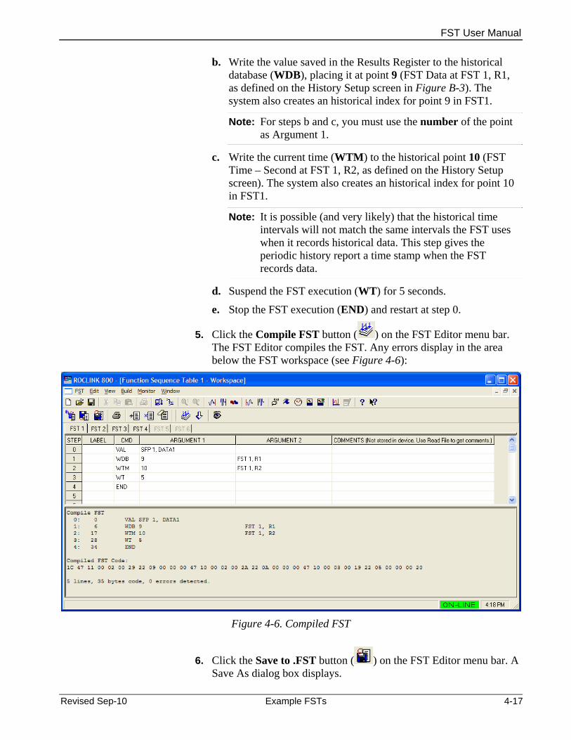
FST User Manual
b. Write the value saved in the Results Register to the historical database (WDB), placing it at point 9 (FST Data at FST 1, R1, as defined on the History Setup screen in Figure B-3). The system also creates an historical index for point 9 in FST1.
Note: For steps b and c, you must use the number of the point as Argument 1.
c. Write the current time (WTM) to the historical point 10 (FST Time – Second at FST 1, R2, as defined on the History Setup screen). The system also creates an historical index for point 10 in FST1.
Note: It is possible (and very likely) that the historical time intervals will not match the same intervals the FST uses when it records historical data. This step gives the periodic history report a time stamp when the FST records data.
d. Suspend the FST execution (WT) for 5 seconds.
e. Stop the FST execution (END) and restart at step 0.
5. Click the Compile FST button ( ) on the FST Editor menu bar. The FST Editor compiles the FST. Any errors display in the area below the FST workspace (see Figure 4-6):
Figure 4-6. Compiled FST
6. Click the Save to .FST button ( ) on the FST Editor menu bar. A Save As dialog box displays.
Revised Sep-10 Example FSTs 4-17

FST User Manual
Figure 4-7. Save As
7. Use this screen to name and save your FST. When you click Save, the FST Editor displays.
Finally, you have to download the FST to the FB107 to make it active.
8. Click the Download button ( ) on the FST Editor menu bar. An FST Details dialog box displays.
Figure 4-8. FST Details
9. Complete at very least the Description field, providing a brief (up to 40 characters) description of the FST.
Note: If you anticipate developing several versions of an FST, complete the Version field so you can easily tell one version from another.
10. Click OK. When the download completes, ROCLINK 800 prompts you to start the FST.
4-18 Example FSTs Revised Sep-10

FST User Manual
Figure 4-9. FST Download completed
At this point the FST is stored in one of the four FST “slots” in the FB107. Click Yes to start the FST or No to return to the FST Editor.
Revised Sep-10 Example FSTs 4-19

FST User Manual
4-20 Example FSTs Revised Sep-10
[This page is intentionally left blank.]
FST User Manual
Index
FST................................................................. 2-9 DWK.................................................................... 3-7 A
ABS.............................................................. 3-4, 4-2 E Absolute Value.................................................... 4-2 End...................................................................... 3-8 Add...................................................................... 4-1 END..................................................................... 3-8 Alarm Log............................................................ 3-8 Erase Workspace.............................................. 2-15 ALM..................................................................... 3-8 Event Log............................................................ 3-8 AND .................................................................... 3-5 EVT ..................................................................... 3-8 AO................................................................ 3-3, 4-7 Examples ............................................................ 4-1 Argument Structure............................................. 2-6
Comparison Commands................................. 4-5 Argument1 .......................................................... 2-6 Argument2 .......................................................... 2-6 Control-Related Commands........................... 4-7 ARGUMENT2 ................................................... 3-10 FST Function .................................................. 2-6
Logical Commands......................................... 4-4 Mathematical Commands............................... 4-1 B Time-Related Commands............................... 4-5 Break................................................................... 3-8 Excel ................................................................. 2-14 Brk..................................................................... 2-19 EXP.............................................................. 3-4, 4-2 BRK..................................................................... 3-8 Exponent............................................................. 4-2 Build FST ............................................................ 2-8
F C Figures Calculating an Execution Rate ......................... 4-13 1-1. FST Functions ......................................... 1-1 CF ..................................................................... 2-19 1-2. FST Registers screen.............................. 1-2 CF Bny.............................................................. 2-19 1-3. FST Registers, General tab (ROC800-
Series) .......................................................... 1-4 Check Timer (CT) ............................................... 3-7 Closing 1-4. FST Registers, General tab .................... 1-4 FST............................................................... 2-14 1-5. FST Registers, Advanced tab (ROC800-
Series) .......................................................... 1-6 CMD.................................................................... 2-6 Command Structure – CMD ............................... 2-6 1-6. FST Registers, Advanced tab ................. 1-6 Comparison Commands ..................................... 4-5 2-1. FST Editor ............................................... 2-1 Compile FST....................................................... 2-8 2-2. FST Editor Toolbar- Compile FST........... 2-8 Configuration 2-3. Compiled FST ......................................... 2-9 FST Editor ...................................................... 1-1 2-4. FST Editor Toolbar - Download............. 2-10 Configuring FSTs.............................................. 4-14 2-5. FST Details Dialog ................................ 2-10 Control-Related Commands ............................... 4-7 2-6. FST Details Dialog ................................ 2-10 Creating 2-7. FST Editor Toolbar ................................ 2-11 FST................................................................. 2-7 2-8. Compile Errors ...................................... 2-16 FST from an Existing File ............................... 2-7 2-9. Monitor FST Screen .............................. 2-18 CT ....................................................................... 3-7 2-10. Trace Mode ......................................... 2-21 Cycling an FST ................................................. 4-13 4-1. History Segment Point Configuration .... 4-11
4-2. FST Editor ............................................. 4-12 D 4-3. History Setup......................................... 4-15
4-4 Blank FST Workspace FST.................... 4-16 Database Commands ......................................... 4-9 4-5 Sample FST ........................................... 4-16 Day of Week (DWK) and Minutes Since Midnight
(MND)................................................................ 3-7 4-6 Compiled FST ........................................ 4-17 4-7 Save As .................................................. 4-18 Delete Step ....................................................... 2-15 4-8 FST Details............................................. 4-18 Deleting 4-9 FST Download completed...................... 4-19 FST (Clear)................................................... 2-13
FST Discrete Output Control Command .................... 4-8 Arguments ...................................................... 2-6 Divide .................................................................. 4-1 Close............................................................. 2-14 DO................................................................ 3-3, 4-8 Command Library ........................................... 3-1 Download
Revised Sep-10 Index I-1
FST User Manual
Logical Commands ............................................. 4-4 Comment Fields ............................................. 2-6 Comparison Commands................................. 3-5 Compile (build) ............................................... 2-8 M Control-Related Commands........................... 3-2 Mathematical Commands ................................... 4-1 Creating New.................................................. 2-7 Message ............................................................. 3-8 Database Commands..................................... 3-9 MISC 1 through MISC 4.................................... 2-20 Defining a History Point................................ 3-11 Miscellaneous Commands.................................. 4-9 Deleting ........................................................ 2-13 MND.................................................................... 3-7 Download ....................................................... 2-9 Monitoring FSTs................................................ 2-16 Editor .............................................................. 1-1 Monitoring load ................................................... 1-2 FST Command Field - CMD........................... 2-6 MPU load FST Editor ...................................................... 1-1 monitoring....................................................... 1-2 Function Examples......................................... 2-6 MS2..................................................................... 3-8 Function Structure .......................................... 2-2 MSG.................................................................... 3-8 Guidelines ...................................................... 2-3 MSG Data ......................................................... 2-20 Historical Commands ................................... 3-12 MSG1................................................................ 2-20 Label Field...................................................... 2-5 MSG2................................................................ 2-20 Logical Commands......................................... 3-4 Multiply................................................................ 4-1 Mathematical Commands............................... 3-3 Miscellaneous Commands ............................. 3-8
N Monitoring..................................................... 2-16 Reading From Device................................... 2-13 NOT .................................................................... 3-5 Reading From File........................................ 2-13 Saving........................................................... 2-11 O Starting ......................................................... 2-11
OR....................................................................... 3-5 Stopping ....................................................... 2-12 Time-Related Commands .............................. 3-6
P Trace Mode .................................................. 2-20 Troubleshooting............................................ 2-15 P3........................................................................ 3-4
FST Editor........................................................... 1-1 PDF................................................................... 2-14 FST Example .................................................... 4-14 Polynomial .......................................................... 4-3
Calculating an Execution Rate ..................... 4-13 Power.................................................................. 4-2 Cycling an FST............................................. 4-13 Print Stopping an FST .......................................... 4-12 FST............................................................... 2-14 Writing Data to a History Point ..................... 4-10
R G
R1 through R10................................................. 2-19 GO ...................................................................... 3-8 RDB .................................................................. 3-10 Guidelines Read
FSTs............................................................... 2-3 FST................................................................. 2-7 Reading
H FST From Device ......................................... 2-13 FST From File............................................... 2-13 History
RF ..................................................................... 2-19 FST Point ..................................................... 3-11 RR..................................................................... 2-19 RTF ................................................................... 2-14 I
Insert Step ........................................................ 2-15 S INT ............................................................... 3-4, 4-2
SAV..................................................................... 3-9 Integer................................................................. 4-2 Saving IP....................................................................... 2-19
FST............................................................... 2-11 Set Timer (ST) .................................................... 3-7 L Size ................................................................... 2-19
Label Structure ................................................... 2-5 SQR ............................................................. 3-4, 4-2 LN ................................................................ 3-4, 4-2 Square Root........................................................ 4-2 LOG ............................................................. 3-4, 4-2 ST ....................................................................... 3-7 Logarithm............................................................ 4-2 Starting
I-2 Index Revised Sep-10

ROC800-Series Instruction Manual
Revised Sep-10 Index I-3
FST............................................................... 2-11 STEP................................................................... 2-2 Stopping
FST............................................................... 2-12 Stopping an FST............................................... 4-12 Subtract............................................................... 4-1
T
Tables 1-1. FST Functionality .................................... 1-1 2-1. Workspace and Output Keystrokes ........ 2-2 2-2. FST Function Structure ........................... 2-2 2-3. FST Label Field....................................... 2-5 2-4. Command Field....................................... 2-6 2-5. FST Function Example............................ 2-7 2-6. Parameter and Data Fields ................... 2-19 2-7. Monitor and Trace Mode Keystrokes .... 2-20 3-1. Command Library Conventions .............. 3-1 3-2. Command Summary ............................... 3-1 3-3. Control Related Commands.................... 3-3 3-4. Mathematical Commands ....................... 3-4 3-5. Logical Commands ................................. 3-5 3-6. Comparison Commands ......................... 3-6 3-7. Time-Related Commands ....................... 3-7 3-8. Miscellaneous Commands ...................... 3-8
3-9. Database Commands............................ 3-10 3-10. Historical Command............................ 3-12
TDO..................................................................... 4-8 Timed Duration Output........................................ 4-8 Timer................................................................... 4-7 Timer 1 through Timer 4 ................................... 2-20 Time-Related Commands................................... 4-5 Trace Mode....................................................... 2-20 Troubleshooting
FSTs ...................................................... 2-3, 2-15
V
VAL ..................................................................... 3-9
W
Wait (WT)............................................................ 3-7 WDB.................................................................. 3-10 Writing Data to a History Point.......................... 4-10 WT....................................................................... 3-7 WTM.................................................................. 3-10
X
XOR .................................................................... 3-5

FST User Manual
If you have comments or questions regarding this manual, please direct them to your local sales representative or contact:
Emerson Process Management Remote Automation Solutions Marshalltown, IA 50158 U.S.A. Houston, TX 77065 U.S.A. Pickering, North Yorkshire UK Y018 7JA Website: www.EmersonProcess.com/Remote
I-4 Index Revised Sep-10