functional operation - aabc commissioning group - … d.doc · web view2 cross-flow cooling towers...
TRANSCRIPT
ACG Commissioning GuidelineAppendix D
Appendix D
Sample Functional Performance Test Checklists
NOTES TO APPENDIX D
This appendix contains sample functional performance test checklists for a number of commonly used HVAC systems. The information for each system includes the following:
1. a description of the system, including its major components, 2. a table showing all modes of operation with the status or position of key
equipment in each mode, 3. a sequence of operations, and4. the functional performance test checklist that corresponds to the preceding
information.
There is no intention in the appendix to provide sample checklists for all possible systems included in any design. These checklists are intended to provide basic information about each system, so that the functional performance test checklists will logically follow from it, and they will illustrate a level of detail that is appropriate in good commissioning practice, and to suggest a practical format.
The sample functional performance test checklists are generic; thus they do not apply to any specific project, and so the list of test items is generic, not specific. Commissioning agencies must develop functional performance test checklists for every system included within the scope of any commissioning project, and those checklists must include every mode of operation and sequence of operation, covering normal, abnormal and emergency conditions that could occur in the specific design.
There is a Table of Contents on the next page listing the sample checklists included in this appendix.
ACG assumes no responsibility for how the material in this Appendix might be utilized by users of the Guideline; the users assume full responsibility for any and all liability that may arise from any reference to, or use of, this material.
Page D-1
ACG Commissioning GuidelineAppendix D
TABLE OF CONTENTS
Chilled Water System.................................................................................................D-4
Water Loop Heat Pump System................................................................................D-15
Make-up Air and Exhaust System.............................................................................D-20
Packaged Rooftop Gas Heat/DX Cool System.........................................................D-23
Variable Air Volume System....................................................................................D-27
Page D-2

CHILLED WATER SYSTEM
SYSTEM DESCRIPTION
The chilled water system is typical of one that may be installed in a large office building.
The system consists of: 3 chillers, CH-1 through CH-3. Chiller CH-1 is smaller than CH-2 and CH-3. 1 plate heat exchanger HE-1. It is located between the condenser water system
(CWS) and the chilled water system (CHWS) in order that condenser water from the cooling towers may be used to directly cool the chilled water without the chiller(s).
2 cross-flow cooling towers CT-1 and CT-2. Each has a high speed and low speed motor driving common shaft mount fans.
A modulating condenser water bypass valve allows the condenser water to bypass the cooling towers in order to maintain flow without going below the temperature set point.
5 chilled water pumps: 2 for the plate heat exchanger P-1 & P-2 and 1 for each chiller P-3, P-4 & P-5
5 condenser pumps: 1 for the plate heat exchanger P-6, 1 for the filter P-7 and 1 for each chiller P-8, P-9 & P-10
A modulating chilled water bypass valve controls the differential pressure across the supply and return piping.
The chilled water distribution system serves cooling coils in air handling units. The system has the following modes of operation:
Shutdown Off Start-up Free cooling (occupied or override) Chiller (override) Chiller (occupied)
Page D-3

CHILLED WATER SYSTEM
MODES OF OPERATION
Shutdown Off Start-up Free Cooling Chiller (override)
Chiller (occupied)
P-1(HE-1 chilled water)
Off Off Off Modulating Off Off
P-2(HE-1 chilled water)
Off Off Off Off/On Off Off
P-6(HE-1 condenser water)
Off Off Off On Off Off
P-3(CH-1 chilled water)
Off Off Off Off On(with CH-1)
Off(except in high load conditions)
P-4(CH-2 chilled water)
Off Off Off Off Off On(with CH-2)
P-5(CH-3 chilled water)
Off Off Off Off Off On(with CH-3)
P-8(CH-1 condenser water)
Off Off Off Off On(with CH-1)
Off(except in high load conditions)
P-9(CH-2 condenser water)
Off Off Off Off Off On(with CH-2)
P-10(CH-3 condenser water)
Off Off Off Off Off On(with CH-3)
CH-1(Chiller) Off Off Off Off
Modulating(after free cooling)
Off(except in high load conditions)
CH-2(Chiller) Off Off Off Off Off
Modulating(lead/lag with
CH-3)
CH-3(Chiller) Off Off Off Off Off
Modulating(lead/lag with
CH-2)CT-1, CT-2(low and high speed fans)
Off Off Off Cycles Cycles Cycles
P-7(Filter) Off Off Off
Cycles(with P-6, 8, 9 &
10)
Cycles(with P-6, 8, 9 &
10)
Cycles(with P-6, 8, 9 &
10)Condenser Water Bypass Valve
Open Open Open Modulating Modulating Modulating
Chilled Water Bypass Valve Open Open Open Closed Modulating Modulating
Condenser Water Make-up Valve
Closed Cycle open/closed
Cycle open/closed
Cycle open/closed
Cycle open/closed
Cycle open/closed
Chilled Water Make-up Valve
Cycle open/closed
Cycle open/closed
Cycle open/closed
Cycle open/closed
Cycle open/closed
Cycle open/closed
Page D-4

CHILLED WATER SYSTEM
SEQUENCE OF OPERATIONS
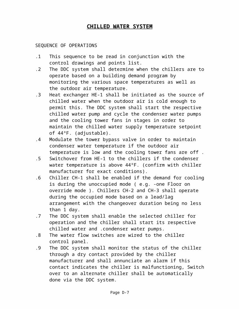
.1 This sequence to be read in conjunction with the control drawings and points list.
.2 The DDC system shall determine when the chillers are to operate based on a building demand program by monitoring the various space temperatures as well as the outdoor air temperature.
.3 Heat exchanger HE-1 shall be initiated as the source of chilled water when the outdoor air is cold enough to permit this. The DDC system shall start the respective chilled water pump and cycle the condenser water pumps and the cooling tower fans in stages in order to maintain the chilled water supply temperature setpoint of 44ºF. (adjustable).
.4 Modulate the tower bypass valve in order to maintain condenser water temperature if the outdoor air temperature is low and the cooling tower fans are off .
.5 Switchover from HE-1 to the chillers if the condenser water temperature is above 44ºF. (confirm with chiller manufacturer for exact conditions).
.6 Chiller CH-1 shall be enabled if the demand for cooling is during the unoccupied mode ( e.g. -one Floor on override mode ). Chillers CH-2 and CH-3 shall operate during the occupied mode based on a lead/lag arrangement with the changeover duration being no less than 1 day.
.7 The DDC system shall enable the selected chiller for operation and the chiller shall start its respective chilled water and .condenser water pumps.
.8 The water flow switches are wired to the chiller control panel.
.9 The DDC system shall monitor the status of the chiller through a dry contact provided by the chiller manufacturer and shall annunciate an alarm if this contact indicates the chiller is malfunctioning, Switch over to an alternate chiller shall be automatically done via the DDC system.
.10 The DDC system shall monitor the status of each purge and annunciate an alarm on a pump failure. The selected chiller shall immediately be shut down and the alternate chiller selected.
.11 The DDC system Shall provide an analog signal (4-20 mA, 2-10 VDC ) to the chiller control panel which shall be used to reset the chilled water supply temperature set point based on the building cooling load, as represented by AHU cooling coil control valve positions. As the CHWR temperature rises above 52ºF the CHWS temperature set point shall be decreased as required If any space temperature is above the acceptable limit the CHWS set point shall be reduced accordingly, The minimum allowable CHWS temperature shall be 42ºF.
.12 The second chiller shall be enabled if the CHWR temperature continues to rise above 54ºF and the lead chiller has been operating at full capacity for at least 20 minutes. If the building occupied mode is nearly over the DDC system shall determine if the lag chiller may be kept off while still maintaining reasonable space conditions. These limits shall be confirmed with the consultant.
.13 Operate all three chillers simultaneously when the cooling load is very high. This shall only be done if it is earlier than 4:00 P.M. (adjustable) and the CHWS temperature is more than 1.0ºF above setpoint.
Page D-5

CHILLED WATER SYSTEM
.14 The DDC system shall modulate the pressure bypass valve between the CHWS line and the CHWR line based on the difference between the two as sensed by a differential pressure transducer in order to maintain water flow through the chillers and HE-1 at all times. The differential pressure setpoint shall be changed to suit the chilled water pump operating at the time.
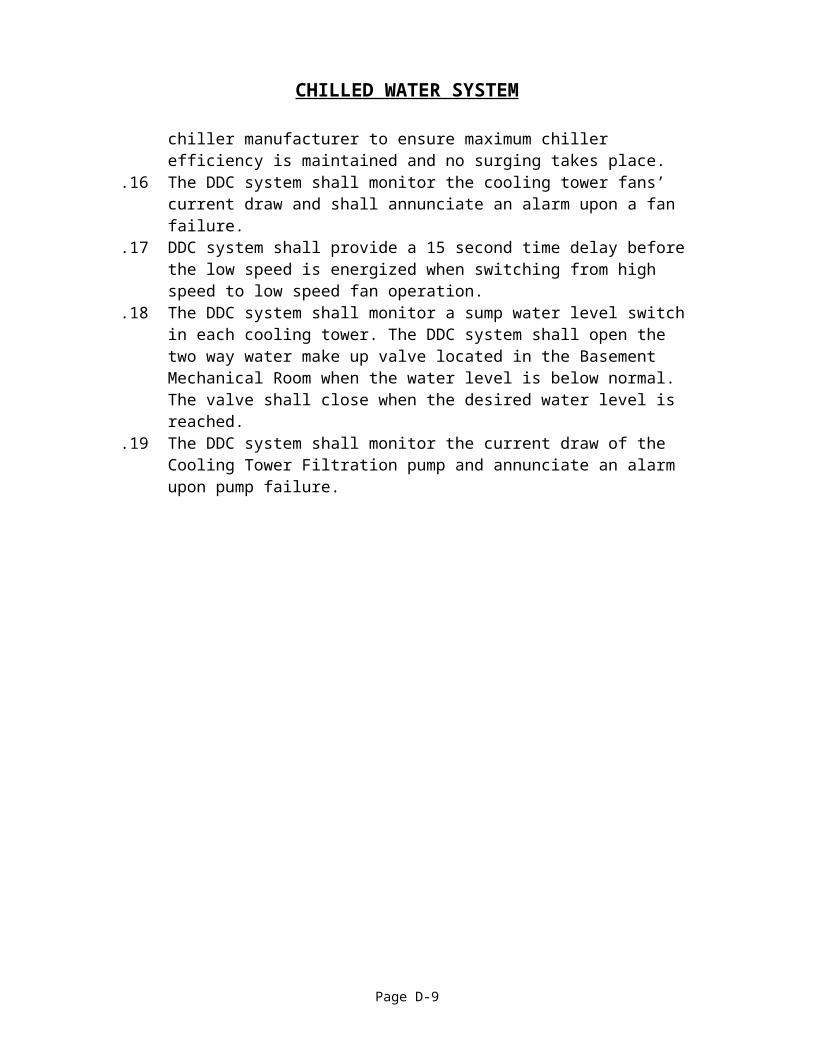
.15 The DDC system shall cycle the cooling tower fans in sequence as required to maintain the condenser water supply temperature set point. This set point is to be initially set at 80ºF but shall be confirmed with the chiller manufacturer to ensure maximum chiller efficiency is maintained and no surging takes place.
.16 The DDC system shall monitor the cooling tower fans’ current draw and shall annunciate an alarm upon a fan failure.
.17 DDC system shall provide a 15 second time delay before the low speed is energized when switching from high speed to low speed fan operation.
.18 The DDC system shall monitor a sump water level switch in each cooling tower. The DDC system shall open the two way water make up valve located in the Basement Mechanical Room when the water level is below normal. The valve shall close when the desired water level is reached.
.19 The DDC system shall monitor the current draw of the Cooling Tower Filtration pump and annunciate an alarm upon pump failure.
Page D-6
HVAC COMMISSIONINGFUNCTIONAL PERFORMANCE TEST CHECKLIST
CHILLED WATER SYSTEM
SEQUENCE OF OPERATION: PASSFAIL NOTE
Shutdown mode: (heating only season) Place the system into a seasonal “shutdown mode” by manual command. Confirm that all 10 pumps (P-1 thru P-10) are commanded OFF by DDC – pump on/off DO
points. Confirm that CT-1 and CT-2 fans, both high & low speed, are commanded OFF by DDC – CT fan
on/off DO points. Confirm that chilled water & condenser water bypass valves are commanded to 100% bypass –
valve AO points = 0. Confirm that cooling tower water make-up solenoid valve is closed, regardless of tower basin
water level – solenoid valve open/close DO point.
Off mode: (cooling season) This mode applies when the system is active (i.e. has been taken out of shutdown mode), but the
chilled water sequence is disabled. Confirm that all 10 pumps (P-1 thru P-10) are commanded OFF by DDC – pump on/off DO
points. Confirm that CT-1 and CT-2 fans, both high & low speed, are commanded OFF by DDC – CT fan
on/off DO points. Confirm that chilled water & condenser water bypass valves are commanded to 100% bypass –
valve AO points = 0. Simulate low water level in CT-1 basin. Confirm that cooling tower water make-up solenoid valve
opens. Simulate normal water level in CT-1; confirm the solenoid valve closes. Repeat for CT-2.
NOTES:1. 2.
Continued on next page:
Page D-7
PROJECT:
System: Location:
Area Served: Equipment:
Checks performed by: Date: print name signature

HVAC COMMISSIONINGFUNCTIONAL PERFORMANCE TEST CHECKLIST
CHILLED WATER SYSTEM
SEQUENCE OF OPERATION: PASSFAIL NOTE
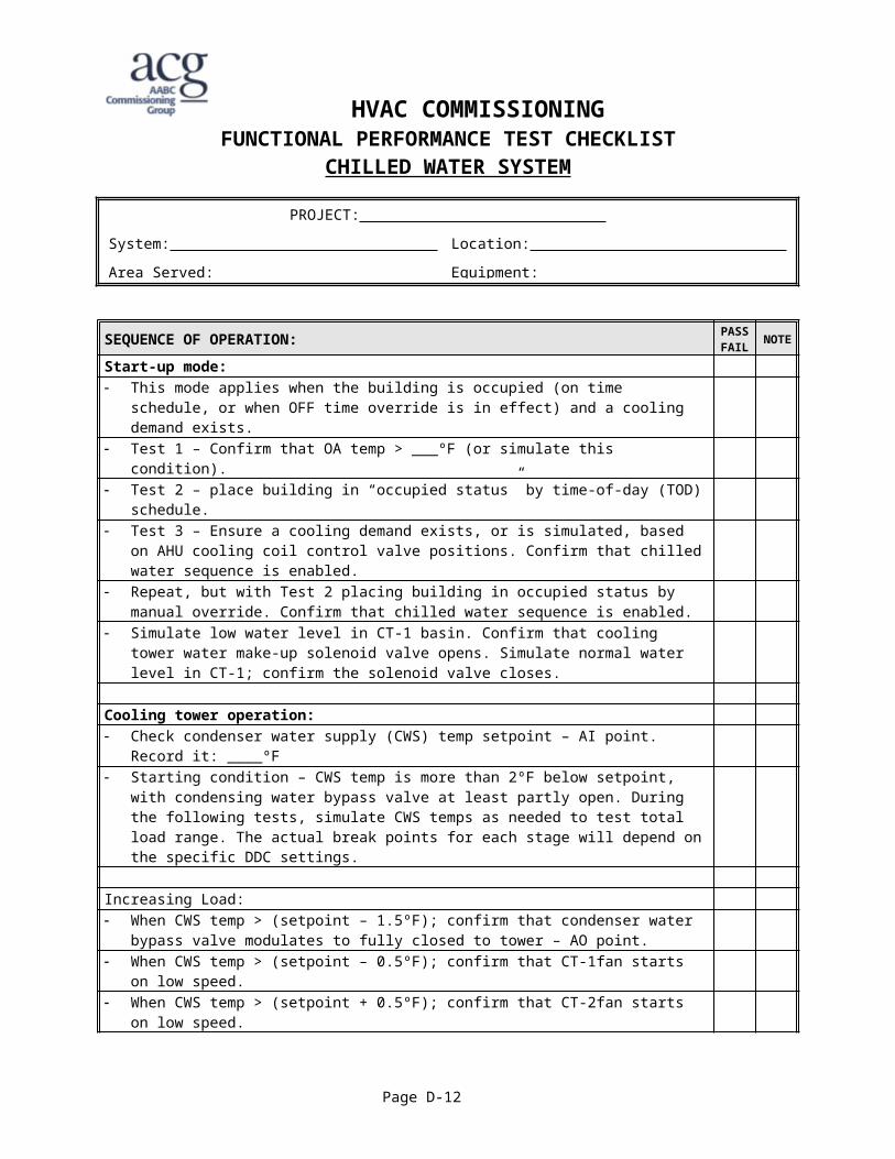
Start-up mode: This mode applies when the building is occupied (on time schedule, or when OFF time override is
in effect) and a cooling demand exists. Test 1 – Confirm that OA temp > ___ºF (or simulate this condition). Test 2 – place building in “occupied status” by time-of-day (TOD) schedule. Test 3 – Ensure a cooling demand exists, or is simulated, based on AHU cooling coil control
valve positions. Confirm that chilled water sequence is enabled. Repeat, but with Test 2 placing building in occupied status by manual override. Confirm that
chilled water sequence is enabled. Simulate low water level in CT-1 basin. Confirm that cooling tower water make-up solenoid valve
opens. Simulate normal water level in CT-1; confirm the solenoid valve closes.
Cooling tower operation: Check condenser water supply (CWS) temp setpoint – AI point. Record it: ____ºF Starting condition – CWS temp is more than 2ºF below setpoint, with condensing water bypass
valve at least partly open. During the following tests, simulate CWS temps as needed to test total load range. The actual break points for each stage will depend on the specific DDC settings.
Increasing Load: When CWS temp > (setpoint – 1.5ºF); confirm that condenser water bypass valve modulates to
fully closed to tower – AO point. When CWS temp > (setpoint – 0.5ºF); confirm that CT-1fan starts on low speed. When CWS temp > (setpoint + 0.5ºF); confirm that CT-2fan starts on low speed. When CWS temp > (setpoint + 1.5ºF); confirm that CT-1fan switches from low-speed to high-
speed. When CWS temp > (setpoint + 2.5ºF); confirm that CT-2fan switches from low-speed to high-
speed.
NOTES:1. 2.
Continued on next page:
Page D-8
PROJECT:
System: Location:
Area Served: Equipment:
Checks performed by: Date: print name signature
HVAC COMMISSIONINGFUNCTIONAL PERFORMANCE TEST CHECKLIST
CHILLED WATER SYSTEM
SEQUENCE OF OPERATION: Continued PASSFAIL
NOTE
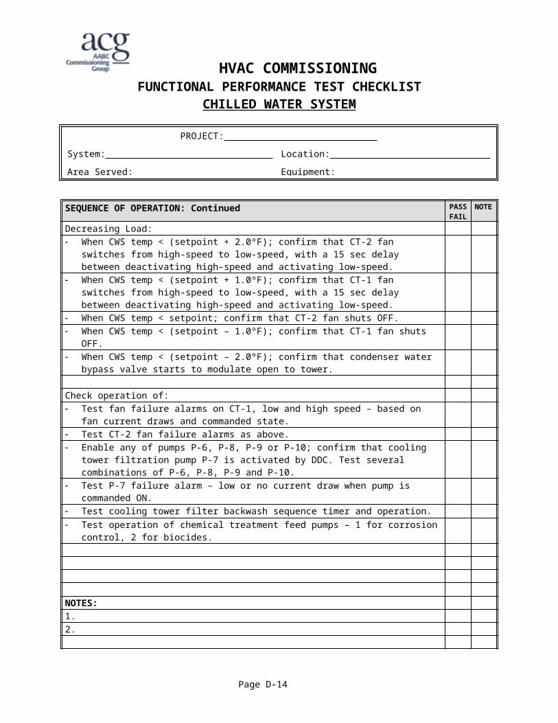
Decreasing Load: When CWS temp < (setpoint + 2.0ºF); confirm that CT-2 fan switches from high-speed to low-
speed, with a 15 sec delay between deactivating high-speed and activating low-speed. When CWS temp < (setpoint + 1.0ºF); confirm that CT-1 fan switches from high-speed to low-
speed, with a 15 sec delay between deactivating high-speed and activating low-speed. When CWS temp < setpoint; confirm that CT-2 fan shuts OFF. When CWS temp < (setpoint – 1.0ºF); confirm that CT-1 fan shuts OFF. When CWS temp < (setpoint – 2.0ºF); confirm that condenser water bypass valve starts to
modulate open to tower.
Check operation of: Test fan failure alarms on CT-1, low and high speed – based on fan current draws and
commanded state. Test CT-2 fan failure alarms as above. Enable any of pumps P-6, P-8, P-9 or P-10; confirm that cooling tower filtration pump P-7 is
activated by DDC. Test several combinations of P-6, P-8, P-9 and P-10. Test P-7 failure alarm – low or no current draw when pump is commanded ON. Test cooling tower filter backwash sequence timer and operation. Test operation of chemical treatment feed pumps – 1 for corrosion control, 2 for biocides.
NOTES:1. 2.
Continued on next page.
Page D-9
Checks performed by: Date: print name signature
PROJECT:
System: Location:
Area Served: Equipment:

HVAC COMMISSIONINGFUNCTIONAL PERFORMANCE TEST CHECKLIST
CHILLED WATER SYSTEM
SEQUENCE OF OPERATION: Continued PASSFAIL NOTE
Free cooling mode – thru heat exchanger: (occupied or override modes) (once per day) When OA temp (AI) < 45ºF (adjustable), confirm that pumps P-2(DO) and P-6(DO) start. When OA temp (AI) > 50ºF (adjustable), confirm that pumps P-2(DO) and P-6(DO) stop.
Chilled water operation: As cooling load increases, so does chilled water flow, thus reducing chilled water system supply
pressure. When supply pressure drops below setpoint, confirm that pump P-1 starts (DO) and modulates
(AO) to maintain CHW supply pressure. When supply pressure rises above setpoint, confirm that after a time delay pump P-1 stops (DO).
Condensing water operation – increasing cooling load: When CHWS temp > (setpoint – 1.0ºF); confirm that condenser water bypass valve modulates to
fully open to tower – AO point. When CHWS temp > (setpoint – 0.5ºF); confirm that CT-1fan starts on low speed. When CHWS temp > (setpoint); confirm that CT-2 fan starts on low speed. When CHWS temp > (setpoint + 0.5ºF); confirm that CT-1fan switches from low-speed to high-
speed. When CHWS temp > (setpoint + 1.0ºF); confirm that CT-2 fan switches from low-speed to high-
speed. When CHWS temp > (setpoint + 1.5ºF), free cooling cannot meet cooling load; confirm that
chiller sequence is enabled. When lead chiller has started; confirm that pumps P-1, P-2 and P-6 stop.
NOTES:1. 2.
Continued on next page:
Page D-10
PROJECT:
System: Location:
Area Served: Equipment:
Checks performed by: Date: print name signature
HVAC COMMISSIONINGFUNCTIONAL PERFORMANCE TEST CHECKLIST
CHILLED WATER SYSTEM
SEQUENCE OF OPERATION: Continued PASSFAIL NOTE
Condensing water operation – decreasing cooling load: Relevant when CHWS temp stays below setpoint + 1.5ºF When CHWS temp < (setpoint + 0.75ºF); confirm that CT-2 fan switches from high-speed to low-
speed, with a 15 sec delay between deactivating high-speed and activating low-speed. When CHWS temp < (setpoint + 0.25ºF); confirm that CT-1 fan switches from high-speed to low-
speed, with a 15 sec delay between deactivating high-speed and activating low-speed. When CHWS temp < (setpoint – 0.25ºF); confirm that CT-2 fan shuts OFF. When CHWS temp < (setpoint – 0.75ºF); confirm that CT-1 fan shuts OFF. When CHWS temp < (setpoint – 1.25 ºF); confirm that condenser water bypass valve starts to
modulate open to bypass.
Check operation of: P-1 status alarm (DI)(aux. contact) P-2 status alarm (DI)(aux. contact) P-6 status alarm (DI)(aux. contact) P-7 status alarm (DI)(aux. contact)
Chiller mode:(override mode:) Confirm that activating manual override enables chiller operation in override mode. CH-1 (DO) enabled when CWS (AI) > 10 C. Pumps P-3 & P-8 hardwire start from CH-1. Chilled water bypass valve (AO) DDC modulates to maintain system differential pressure (AI)
setpoint CH-1 (AO) CHWS setpoint (AI) is reset from demand based on the AHU ** CHW control valve
(AO) position and the CHWR (AI) temperature.
NOTES:1. 2.
Continued on next page:
Page D-11
PROJECT:
System: Location:
Area Served: Equipment:
Checks performed by: Date: print name signature
HVAC COMMISSIONINGFUNCTIONAL PERFORMANCE TEST CHECKLIST
CHILLED WATER SYSTEM
SEQUENCE OF OPERATION: Continued PASSFAIL NOTE
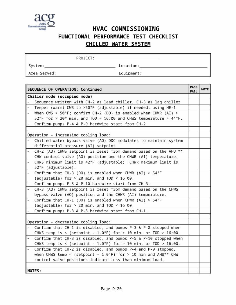
Chiller mode (occupied mode) Sequence written with CH-2 as lead chiller, CH-3 as lag chiller Temper (warm) CWS to >50ºF (adjustable) if needed, using HE-1 When CWS > 50ºF; confirm CH-2 (DO) is enabled when CHWR (AI) > 52ºF for > 20* min. and
TOD < 16:00 and CHWS temperature > 44ºF. Confirm pumps P-4 & P-9 hardwire start from CH-2
Operation – increasing cooling load: Chilled water bypass valve (AO) DDC modulates to maintain system differential pressure (AI)
setpoint CH-2 (AO) CHWS setpoint is reset from demand based on the AHU ** CHW control valve (AO)
position and the CHWR (AI) temperature. CHWS minimum limit is 42ºF (adjustable); CHWR maximum limit is 52ºF (adjustable). Confirm that CH-3 (DO) is enabled when CHWR (AI) > 54ºF (adjustable) for > 20 min. and TOD
< 16:00. Confirm pumps P-5 & P-10 hardwire start from CH-3. CH-3 (AO) CHWS setpoint is reset from demand based on the CHWS bypass valve (AO) position
and the CHWR (AI) temperature. Confirm that CH-1 (DO) is enabled when CHWR (AI) > 54ºF (adjustable) for > 20 min. and TOD
< 16:00. Confirm pumps P-3 & P-8 hardwire start from CH-1.
Operation – decreasing cooling load: Confirm that CH-1 is disabled, and pumps P-3 & P-8 stopped when CHWS temp is < (setpoint –
1.0ºF) for > 10 min. or TOD > 16:00. Confirm that CH-3 is disabled, and pumps P-5 & P-10 stopped when CHWS temp is < (setpoint –
1.0ºF) for > 10 min. or TOD > 16:00. Confirm that CH-2 is disabled, and pumps P-4 and P-9 stopped, when CHWS temp < (setpoint –
1.0ºF) for > 10 min and AHU** CHW control valve positions indicate less than minimum load.
NOTES:1. 2.
Continued on next page:
Page D-12
PROJECT:
System: Location:
Area Served: Equipment:
Checks performed by: Date: print name signature

HVAC COMMISSIONINGFUNCTIONAL PERFORMANCE TEST CHECKLIST
CHILLED WATER SYSTEM
SEQUENCE OF OPERATION: Continued PASSFAIL NOTE
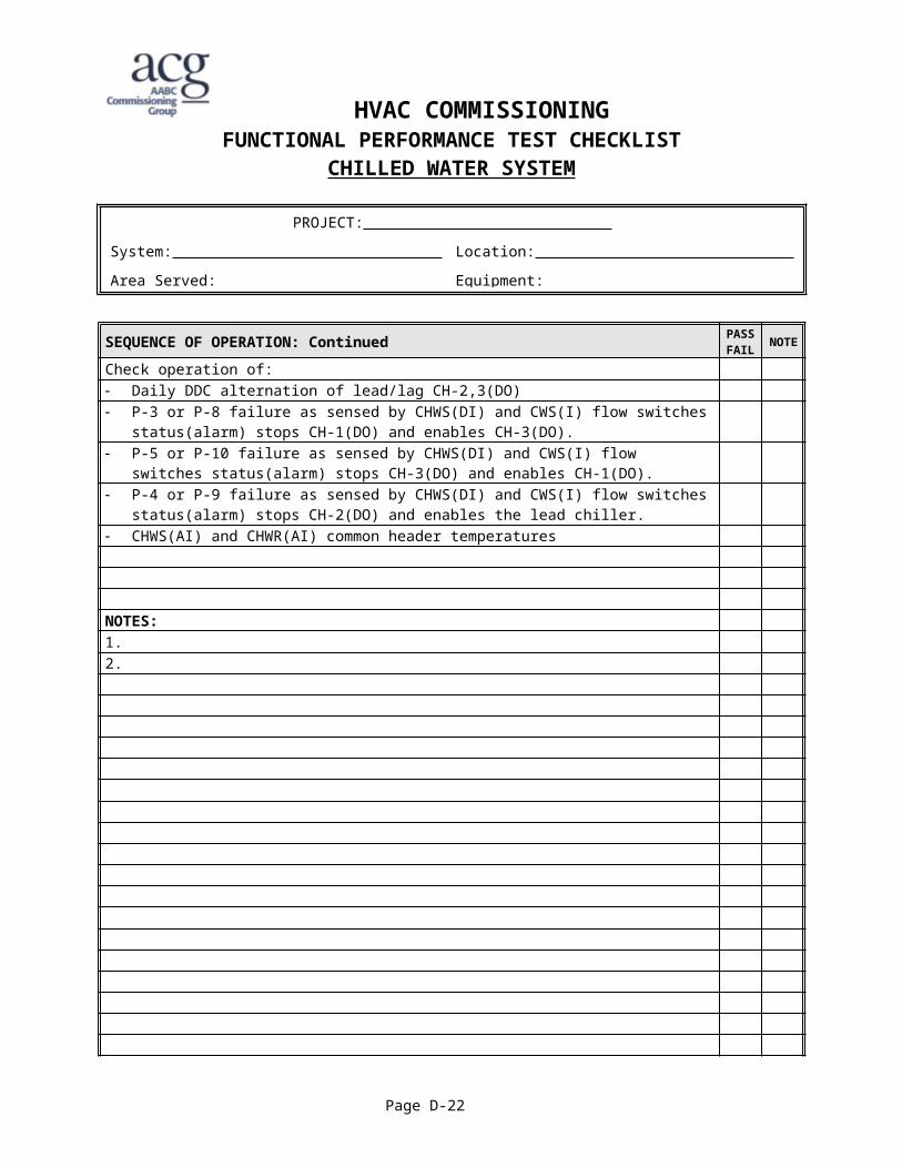
Check operation of: Daily DDC alternation of lead/lag CH-2,3(DO) P-3 or P-8 failure as sensed by CHWS(DI) and CWS(I) flow switches status(alarm) stops CH-
1(DO) and enables CH-3(DO). P-5 or P-10 failure as sensed by CHWS(DI) and CWS(I) flow switches status(alarm) stops CH-
3(DO) and enables CH-1(DO). P-4 or P-9 failure as sensed by CHWS(DI) and CWS(I) flow switches status(alarm) stops CH-
2(DO) and enables the lead chiller. CHWS(AI) and CHWR(AI) common header temperatures
NOTES:1. 2.
Page D-13
Checks performed by: Date: print name signature
PROJECT:
System: Location:
Area Served: Equipment:
WATER LOOP HEAT PUMP SYSTEM
SYSTEM DESCRIPTION
The water loop heat pump system is typical of one that may be installed in retail, commercial, or office buildings. Each ceiling-space mounted heat pump serves a specific zone of the building.
The system consists of water loop piping throughout the building with: water loop temperature control panel (probably DDC) with return water
temperature sensor and flow switch single stage gas fired hot water boiler (B-1) on a branch circuit with a circulation
pump (P-1) heat rejecter (HR-1) with packaged controls (external reset), cooling coil,
isolation damper, fan, spray pump, sump heater and drain 2 parallel main loop circulation pumps (P-2 & P-3) a heat pump for each zone (HP-1, HP-2, etc.) with local heating/cooling
thermostat.
The ceiling space is provided with a separate source of outside air. The outside air ventilation system is not included in this sample system.
The system has the following modes of operation: Off (Shutdown) Start-up No load demand - mixed heating/cooling Heating Cooling
MODES OF OPERATION
Water LoopOff (Shutdown) Start-up No load Heating Cooling
B-1(boiler) Off Off Off On Off
P-1(boiler pump) Off Off Off On Off
HR-1 Damper(Heat rejecter) Closed Closed Closed Closed Open
HR-1 Fan(Heat rejecter) Off Off Off Off Cycles
(Off/On)HR-1 Spray Pump(Heat rejecter) Off Off Off Off Cycles
(Off/On)P-2(main water loop) Off On
(lead/lag)On
(lead/lag)On
(lead/lag)On
(lead/lag)
P-3(main water loop) Off Off
(lead/lag)Off
(lead/lag)Off
(lead/lag)Off
(lead/lag)
Page D-14
WATER LOOP HEAT PUMP SYSTEM
Heat PumpsOff (Shutdown) Start-up No demand Heating Cooling
Fan Off On On On On Compressor Off Off Off On On Reversing Valve - - - Heat Cool
SEQUENCE OF OPERATIONS
1.1 MAIN WATER LOOP.20 The main water loop circulates water 24/7..21 The main water loop circulation pumps operate on a lead/lag/backup basis..22 The packaged heat rejecter shall be enabled from the main water loop controller
based on the loop heat rejection demand as sensed by the main water loop return water temperature sensor. The local packaged heat rejecter controls shall operate the damper, fan and spray pump to maintain setpoint as determined (enabled/ disabled) by the main water loop controller.
.23 The main water loop controller shall cycle the boiler off and on to maintain the water loop return water temperature setpoint. The boiler circulation pump shall be switched by the boiler and an inline flow switch in the boiler branch line shall allow the boiler to fire.
1.1 HEAT PUMPS.1 Local heating/cooling thermostats shall control the heat pumps. These shall allow
4 time-of-day setpoints(programs) and auto/manual fan control.
Page D-15

HVAC COMMISSIONINGFUNCTIONAL PERFORMANCE TEST CHECKLIST
WATER LOOP HEAT PUMP SYSTEM
SEQUENCE OF OPERATION: PASSFAIL
NOTE
MAIN WATER LOOPStart up mode: Initiate water-loop circulation DDC start-up sequence, with P-2 as lead pump. Confirm that P-2 starts and runs. Confirm that water-loop flow switch confirms flow (P-2 status = ON) Simulate failure of P-2; confirm (1) that water-loop flow switch indicates no flow, (2) that P-2
no-flow alarm is generated, and (3) that lag pump P-3 starts and runs.
No load mode: Applies when water-loop return water temp. is between minimum and maximum setpoints of
40ºF and 90ºF. Confirm that either P-2 or P-3 are ON. Confirm that P-1 and B-1 are OFF; i.e. water loop does not require any supplementary heat. Confirm that HR-1 is OFF; i.e. water loop does not require any heat rejection.
Heating mode: Applies when water loop return temp. (WLRT) is at or below minimum setpoint. On decreasing WLRT, if WLRT < (min. setpoint – 1.0ºF), confirm that B-1 is enabled. Confirm
sequence of P-1 start, boiler loop flow switch indicating flow, and that B-1 then fires. On increasing WLRT, if WLRT > (min setpoint + 1.0ºF), confirm that B-1 is disabled and that
B-1 stops, and P-1 stops after a time delay of ____ sec..
NOTES:1. 2.
Continued on next page.
Page D-16
PROJECT:
System: Location:
Area Served: Equipment:
Checks performed by: Date: print name signature

HVAC COMMISSIONINGFUNCTIONAL PERFORMANCE TEST CHECKLIST
WATER LOOP HEAT PUMP SYSTEM
SEQUENCE OF OPERATION: PASSFAIL
NOTE
MAIN WATER LOOP (cont’d)Cooling mode: Applies when water loop return temp. (WLRT) is at or below minimum setpoint.
On increasing WLRT: If WLRT > (max setpoint), confirm that HR-1 damper is enabled, and it OPENS. If WLRT > (max setpoint + 2.0ºF), confirm that HR-1 fan is enabled, and it STARTS & RUNS. If WLRT > (max setpoint + 4.0ºF), confirm that HR-1 spray pump is enabled, and it STARTS &
RUNS.
On decreasing WLRT: If WLRT < (max setpoint + 1.0ºF), confirm that HR-1 spray pump is disabled, and STOPS. If WLRT < (max setpoint - 1.0ºF), confirm that HR-1 fan is disabled, and STOPS. If WLRT < (max setpoint - 3.0ºF), confirm that HR-1 damper is disabled, and it CLOSES.
Check operation of: HR-1 sump level control, water makeup (local HR control) HR-1 sump heater (local HR control) – confirm heater is locked out when OA temp > 40ºF
HEAT PUMPSCheck operation of individual heat pumps using the local heating and cooling thermostats: off/on switch – entire heat pump is either OFF or ON (ready for operation upon thermostat signal. fan on/auto switch – ON = fans operates constantly; AUTO = fan operates only when compressor
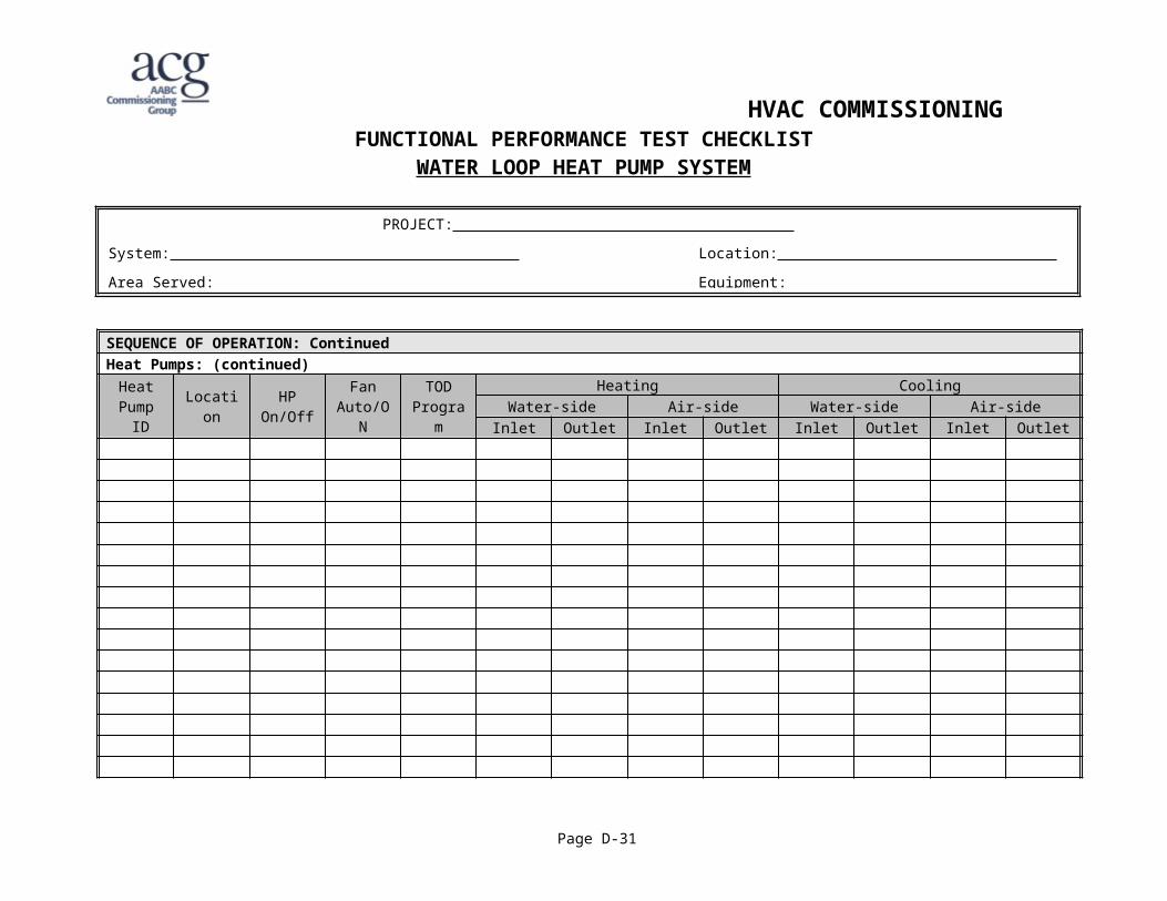
operates. time-of-day programsCheck air and water, inlet and outlet temperatures
NOTES:1. 2.
Page D-17
Checks performed by: Date: print name signature
PROJECT:
System: Location:
Area Served: Equipment:

HVAC COMMISSIONINGFUNCTIONAL PERFORMANCE TEST CHECKLIST
WATER LOOP HEAT PUMP SYSTEM
SEQUENCE OF OPERATION: ContinuedHeat Pumps: (continued)
HeatPump
IDLocation HP
On/OffFan
Auto/ONTOD
Program
Heating CoolingWater-side Air-side Water-side Air-side
Inlet Outlet Inlet Outlet Inlet Outlet Inlet Outlet
Comments:
Page D-18
Checks performed by: Date: print name signature
PROJECT:
System: Location:
Area Served: Equipment:

MAKE-UP AIR AND EXHAUST SYSTEM
SYSTEM DESCRIPTION
This make-up air and exhaust system is typical of one that may be installed in a commercial/industrial building serving a specific area of the building where there is a need to supply 100% outside air to balance a significant exhaust air requirement. Examples of this are industrial shops, kitchens, boiler rooms, etc.
The system consists of: ceiling mounted supply fan (SF) ducted to the outside air with:
motorized inlet (supply) open/closed damper (OAD) hot water heating coil and control valve (HCV)
roof mounted exhaust fan (EF) with barometric back-draft damper. controls
by a central DDC system space and supply air temperature sensors fan motor current relays freezestat
air distribution ductwork with supply and exhaust grilles (constant volume)
MODES OF OPERATION
Off Unoccupied (System
Off)
Occupied
Equipment Shutdown Freezestat(activated)
OAD(dampers) Closed Closed Closed Open
SF(fan) Off Off Off On
EF(fan) Off Off Off On
HCV(valve) Closed Open Closed Modulating
Page D-19
MAKE-UP AIR AND EXHAUST SYSTEM
SEQUENCE OF OPERATIONS
1.1 OCCUPIED MODE.2 Occupied mode shall be determined by the time-of-day (TOD) programming..3 The supply fan (SF) shall start/stop from a hard-wired connection to the outside
air damper (OAD) limit switch. The outside air damper shall be open/closed by the DDC system.
.4 The supply fan shall run continuously.
.5 The exhaust fan shall be started by the DDC system once the supply fan status is proved on.
.6 The heating control valve (HCV) shall modulate to maintain the supply air temperature setpoint.
1.2 UNOCCUPIED MODE.1 Unoccupied mode shall be determined by the time-of-day (TOD) programming..2 Outside air damper closed, supply fan off, heating control valve closed, unless
outside air temperature is less than 30ºF, and exhaust fan off.
1.3 FREEZE PROTECTION.1 A hard-wired freezestat shall stop the supply fan, close the outside air damper and
open the heating control valve 100%..2 The exhaust fan shall be stopped by the DDC system..3 The heating control valve shall be opened prior to running the supply fan in cold
weather.
1.4 ALARMS.1 The DDC system shall annunciate an alarm when:
- the freezestat is actuated- the supply fan fails to start (indicated by motor amps)- the exhaust fan fails to start (indicated by motor amps)- the supply air temperature is lower than ___F.
Page D-20

HVAC COMMISSIONINGFUNCTIONAL PERFORMANCE TEST CHECKLIST
MAKE-UP AIR AND EXHAUST SYSTEM
SEQUENCE OF OPERATION: PASSFAIL
NOTE
Start-up: If OA temp < ___ ºF, confirm that heating coil valve (HCV) opens 100% for ___ seconds prior
to opening OA damper and starting supply fan. Confirm that OA damper opens. Confirm that when OA damper is open, as sensed by limit switch, that supply fan (SF) starts. When supply airflow is proven, confirm that exhaust fan (EF) starts.
Heating:Occupied mode: Confirm that HCV modulates to maintain the supply air temperature (SAT) setpoint of ___ ºFUnoccupied mode: As the makeup air system does not provide primary space heating, confirm that SF and EF stay
OFF, and HCV stays closed unless freezestat has been triggered (see below).
Freeze Protection:Trip the freezestat (manually, or with an ice pack). Confirm that the following actions occur: SF stops OA damper closes tightly HCV opens 100% to heat EF stops Freezestat alarm is generated
Alarms and status indications: Simulate SF failure; confirm SF failure alarm is generated Simulate EF failure; confirm EF failure alarm is generated When supply fan is ON, simulate SAT < (setpoint – 3.0ºF); confirm low SAT alarm is generated. When SF is OFF, simulate SAT < (setpoint – 3.0ºF); confirm low SAT alarm is NOT generated.
NOTES:1. 2.
Page D-21
PROJECT:
System: Location:
Area Served: Equipment:
Checks performed by: Date: print name signature
PACKAGED ROOFTOP GAS HEAT/DX COOL SYSTEM
SYSTEM DESCRIPTION
The roof top unit is typical of one that may be installed in a commercial/industrial/office building serving a specific area of the building.
The system consists of: packaged roof top unit(RTU) with:
supply fan (SF) modulating outside-air, return-air and relief dampers (MAD) operated by a
single motor gas heating with a single stage burner (GB) D/X cooling (DX) with single stage compressor, 2 coils and fan.
local unit controller (usually supplied by unit manufacturer or other dedicated controller) c/w: outside and supply air temperature sensors. heating/cooling thermostat
air distribution ductwork with supply and return grilles (constant volume)
MODES OF OPERATION
Off(Shutdown) Unoccupied Occupied
Equipment Off Heating Free Cooling Heating CoolingMAD(dampers)
Closed(to OA)
Closed(to OA)
Closed(to OA) Modulating Minimum
(O/A)Minimum
(O/A)SF(fan) Off Off On On On On
GB(burner) Off Off On Off On Off
DX(comp. and cond. fan)
Off Off Off Off Off On
Page D-22
PACKAGED ROOFTOP GAS HEAT/DX COOL SYSTEM
SEQUENCE OF OPERATIONS
1.1 OCCUPIED MODE.2 Occupied mode shall be determined by the time-of-day (TOD) programming..3 The supply fan shall run continuously..4 The mixed air dampers shall modulate to provide free cooling (economizer
operation) as determined by the supply air temperature (SAT) and the outside air temperature(OAT).
.5 The mixed air dampers shall be positioned to provide minimum outside air when the unit is in either gas heating or D/X cooling modes.
.6 The gas burner shall cycle on/off to maintain the space temperature heating setpoint.
.7 The D/X cooling shall cycle on/off to maintain the space temperature cooling setpoint when the economizer operation is unable to maintain the cooling setpoint.
1.5 UNOCCUPIED MODE.1 Unoccupied mode shall be determined by the time-of-day (TOD) programming..2 The supply fan and gas burner shall cycle on/off as required to meet the set-back
heating setpoint..3 The mixed air dampers shall be closed to the outside air.
Page D-23

HVAC COMMISSIONINGFUNCTIONAL PERFORMANCE TEST CHECKLIST
PACKAGED ROOFTOP GAS HEAT/DX COOL SYSTEM
SEQUENCE OF OPERATION: PASSFAIL
NOTE
Occupied mode: Confirm that SF is ONWhen heating is required, confirm that: MAD is positioned to minimum OA setpoint (value set by TAB agency). DX cooling if OFF GB cycles ON/OFF to maintain space heating temp. setpoint.Record the following data: OA temp. ____ ºF Max. space temp., when GB stops ____ ºF; Min. space temp., when GB starts ____ ºF Max. supply air temp. (SAT) ____ ºF; Min. SAT ____ ºF
When heating is not required, and free cooling can maintain space temp below cooling setpoint, confirm that: GB and DX cooling are both OFF. MAD modulates from min. OA position to 100% open to OA, to maintain space cooling setpoint
____ ºFWhen cooling is required, confirm that: MAD is positioned to minimum OA setpoint (value set by TAB agency). DX cooling cycles ON/OFF to maintain space cooling temp. setpoint.Record the following data: OA temp. ____ ºF Max. space temp., when DX starts ____ ºF; Min. space temp., when DX stops ____ ºF Max. supply air temp. (SAT) ____ ºF; Min. SAT ____ ºF
NOTES:1. 2.
Continued on next page:
Page D-24
PROJECT:
System: Location:
Area Served: Equipment:
Checks performed by: Date: print name signature

HVAC COMMISSIONINGFUNCTIONAL PERFORMANCE TEST CHECKLIST
PACKAGED ROOFTOP GAS HEAT/DX COOL SYSTEM
SEQUENCE OF OPERATION: PASSFAIL
NOTE
Unoccupied mode:
When space temp. > night setback heating setpoint, confirm that: MAD is tightly closed to OA. Heating and cooling are both OFF Supply fan (SF) is OFF.
When space temp. < night setback heating, confirm than: MAD stays tightly closed to OA and cooling stays OFF. SF is started Gas heating (GB) fires When space temp. rises to > night setback heating setpoint, confirm GB and SF turn OFF.
NOTES:1. 2.
Page D-25
Checks performed by: Date: print name signature
PROJECT:
System: Location:
Area Served: Equipment:

VARIABLE AIR VOLUME SYSTEM
SYSTEM DESCRIPTION
The air handling system is typical of one that may be installed in a commercial/industrial building serving a specific area or floor of the building.
The system consists of: air handling unit(AHU) with:
supply fan with variable speed drive (VSD) motor control modulating outside-air, return-air and relief dampers heating and cooling coils steam humidification air filters
coil circulation pumps modulating heating coil control valve (HCV) and cooling coil control valve
(CCV) return fan variable air volume (VAV) boxes with DDC controllers direct digital control (DDC) system
The AHU has ducted access to untempered outside air.
The supporting steam, heating and cooling water systems are outside the scope of this example.
The system has various modes of operation: Off (Shutdown) Start-up Warm-up Normal Economizer Fire Freeze
Page D-26

VARIABLE AIR VOLUME SYSTEM
MODES OF OPERATION
Equipment Shutdown Normal Operation
Normal Fire Freeze Free Cooling. Heating Cooling Night
HeatingOutdoor Air Damper
Closed Open Closed Modulating Minimum Modulating
Return Air Damper Open Closed Open Modulating Modulating Modulating Modulating
Relief Air Damper Closed Open Closed Modulating Modulating Modulating Modulating
Heating Coil Pump Off On On Off On Off On
Heating Coil control valve
Closed Modulating Open Closed Modulating Closed Modulating
SF-1 Off On Off On On On OnHumidifier enable Closed Closed Closed Open Open Closed Open
HU-1 control valve
Closed Closed Closed Modulating Modulating Closed Modulating
Cooling coil control valve
Closed Modulating Closed Closed Closed Modulating Closed
RF-1 Off On Off On On On On
Page D-27

VARIABLE AIR VOLUME SYSTEM
SEQUENCE OF OPERATIONS
1.1 GENERAL.4 On a signal to start the supply and return fans, open the return air dampers and
crack the outdoor air damper (5% open)..5 Start the supply and return (AHU-1 only) fans on a minimum speed..6 After fan status is proven, modulate the dampers in a normal manner..7 Modulate the speed of the supply fans to maintain the required duct static
pressure..8 Modulate the speed of the return fan to maintain the required building
pressurization. Use the volume probes to determine the appropriate return volume (i.e. return volume = supply volume + building pressurization volume; where the building pressurization volume is to be determined on site).
.9 On a signal to start an exhaust fan, open its motorized damper. When the damper end switch is made, start the fan.
.10 When no heating is required, the mixing dampers shall modulate to provide the amount of free cooling (up to 100% outdoor air) required to maintain the supply air temperature (SAT) setpoint.
.11 When the dampers are at the minimum outdoor air position, heating shall be allowed. When the dampers are at the 100% outdoor air position, cooling shall be allowed.
.12 When the outdoor air temperature (OAT) is below 40ºF, start the heating coil circulating pump whether the fan is running or not.
.13 When cooling is required, modulate the cooling coil valve, start pump P-2 to maintain the required SAT setpoint.
.14 The SAT shall be reset from the system’s associated room temperature sensors.
.15 A return air humidity sensor and a supply air high limit humidity sensor shall control the humidifiers. On a call for humidification, the humidifier isolation valve shall open. After unit heat up has been proven by an internal temperature switch, the humidifier control valves shall modulate to maintain the required humidity, subject to the supply air high limit. The humidifiers shall only operate if the associated supply fan is on.
.16 Install a low temperature sensor on the discharge side of the heating coil, (set for approx. 40ºF). On a low temperature alarm, shut off the fans, enable the heating coil pump, and open the heating coil valve.
Page D-28

VARIABLE AIR VOLUME SYSTEM
1.6 VAV BOXES.1 Modulate the control damper to maintain the required room temperature..2 (For those boxes with reheat coils) If heating is required, modulate the 2-way
reheat control valve to maintain the required room temperature with the control damper set at minimum airflow position.
.3 Switch the box mode between “day” and “night” modes based on time-of-day or operator command.
Page D-29

HVAC COMMISSIONINGFUNCTIONAL PERFORMANCE TEST CHECKLIST
VARIABLE AIR VOLUME SYSTEM
SEQUENCE OF OPERATION: PASSFAIL NOTE
Unoccupied mode: Confirm that: Supply fan (SF) is OFF and its VFD speed = 0% Return fan (RF) is OFF and its VFD speed = 0% MAD is tightly closed to OA. Humidifier control valve is fully closed (AO = 0%) VAV boxes are in unoccupied “night” mode.
If OAT ≥ 41 ºF then confirm that: HWH coil pump is OFF Heating coil control valve (HCV) is closed to 0%
If OAT < 40ºF, then confirm that: HWH coil pump starts and runs HCV moves to 10% open position.
Start up mode: Simulate time of day (TOD) to start of occupied hours.
Confirm that fan start-up sequence occurs as follows: If avg. space temp (from VAV box sensors) < (occupied heating setpoint – 2.0ºF), then MAD
stays closed to OA, otherwise MAD opens to 5% OA. SF and RF start at minimum VFD speed When SF operating status is proven, modulate fan speed to maintain supply duct static pressure
at setpoint ____ “ WG When RF operating status is proven, modulate fan speed to maintain building pressure at setpoint
____ “ WG HU-1 humidifier isolation valve opens when return air relative humidity < 35% VAV boxes move from unoccupied mode to occupied “day” mode
NOTES:1. 2.
Continued on next page:
Page D-30
PROJECT:
System: Location:
Area Served: Equipment:
Checks performed by: Date: print name signature
HVAC COMMISSIONINGFUNCTIONAL PERFORMANCE TEST CHECKLIST
VARIABLE AIR VOLUME SYSTEM
SEQUENCE OF OPERATION: PASSFAIL NOTE
Warm-up: MAD stays closed to OA until avg. space temp > occupied heating setpoint. When avg. space temp > occupied setpoint, then MAD moves to min. OA position, ____ % OA
Occupied “normal” mode:Confirm supply air temp. (SAT) setpoint reset logic. Min. SAT setpoint = ____ ºF; max. SAT setpoint = ____ ºF When avg. space temp. > (cooling setpoint + 1.0ºF), confirm that SAT setpoint = min. When avg. space temp. < (heating setpoint – 1.0ºF), confirm that SAT setpoint = max.
SAT control:If SAT < (setpoint – 1.0ºF), confirm that: MAD is at min. OA position Cooling coil pump of OFF and CCV is closed. HCV modulates to maintain SAT = (setpoint – 1.0ºF). Heating coil pump starts when HCV > 10% open; stops when HCV < 5% open. Except if OA temp < 40ºF, then heating coil pump is ON at all times.
If SAT > setpoint, and < (setpoint + 1.0ºF), confirm that: Heating coil pump is OFF, and HCV is closed. Cooling coil pump is OFF and CCV is closed. MAD modulates between min. position and 100% OA to maintain SAT = setpoint.
NOTES:1. 2.
Continued on next page:
Page D-31
PROJECT:
System: Location:
Area Served: Equipment:
Checks performed by: Date: print name signature
HVAC COMMISSIONINGFUNCTIONAL PERFORMANCE TEST CHECKLIST
VARIABLE AIR VOLUME SYSTEM
SEQUENCE OF OPERATION: PASSFAIL NOTE
Occupied (normal) mode(continued):
If SAT > (setpoint + 1.0ºF), confirm that: MAD is at 100% OA position if return air temp. (RAT) ≥ OA temp.; or at min. position if RAT <
OA temp. Heating coil pump is OFF, and HCV is closed. CCV modulates to maintain SAT + (setpoint + 1.0ºF) Cooling coil pump starts when CCV > 10% open; stops when CCV < 5% open.
Humidity: Confirm that humidifier is OFF when HCV < 5% open. When humidifier is enabled, confirm that HU-1 control valve modulates to maintain return air
RH = setpoint. Confirm that the humidity control valve action is delayed 10 minutes after the isolation valve
opens.
Fire mode: Hardwire stop SF from fire alarm system wired to SF speed controllerConfirm that: SF stops – DO = OFF, SF VFD = 0% RF stops – DO = OFF, RF VFD = 0% MAD moves to 0% OA position Humidifier stops – control valve = 0% open, and isolation valve closed. VAV boxes go to unoccupied “night” mode.
NOTES:1. 2.
Continued on next page:
Page D-32
PROJECT:
System: Location:
Area Served: Equipment:
Checks performed by: Date: print name signature

HVAC COMMISSIONINGFUNCTIONAL PERFORMANCE TEST CHECKLIST
VARIABLE AIR VOLUME SYSTEM
SEQUENCE OF OPERATION: PASSFAIL NOTE
Freeze mode: On low temperature freezestat(DI) (auto reset type) ≤ 40ºF for 10 seconds.:Confirm that: SF hardwire stopped while freezestat activated as above. SF stops – DO = OFF, SF VFD = 0% RF stops – DO = OFF, RF VFD = 0% MAD moves to 0% OA position Humidifier stops – control valve = 0% open, and isolation valve closed. Heating coil pump starts and HCV goes to 10% open position.Confirm that freeze mode can be reset by operator toggling DDC “freeze reset point”.
Alarms and status checks: SAT (AI) RAT (AI) Filter high DP (AI). HWH coil pump status(AI) CHW coil pump status(AI) SF status (AI)
NOTES:1. 2.
Continued on next page.
Page D-33
Checks performed by: Date: print name signature
PROJECT:
System: Location:
Area Served: Equipment:

HVAC COMMISSIONINGFUNCTIONAL PERFORMANCE TEST CHECKLIST
VARIABLE AIR VOLUME SYSTEM
SEQUENCE OF OPERATION: Continued VAV Boxes:
The VAV boxes shall modulate the damper and Reheat HCV to maintain the DDC room setpoint during “day mode” and “night mode” ( different setpoints in each VAV box controller).Simulate heating and cooling conditions.
VAV ID Location Day Mode Night Mode Heating Cooling
Comments:
Page D-34
Checks performed by: Date: print name signature
PROJECT:
System: Location:
Area Served: Equipment: