functional specification for smart translink...
TRANSCRIPT

March 8th, 2012 Dr. Andrew Rawicz Simon Fraser University Burnaby, British Columbia V5A 1S6 Re: ENSC 440 Functional Specifications for Smart TransLink System Dear Dr. Rawicz,
Attached is our Design Specification document which outlines the guidelines followed by
TransNet in order to model the Smart Translink System. This system provides a new method of
payment that helps prevent fraud and will help Translink better allocate its resources to
operate more efficiently using RFID readers and tags.
This document will be used throughout the design and development cycle of this project to
ensure that proper guidelines are being followed and required stability and performance are
met. Furthermore, the document is used to apply and proof the concept model for this project.
Any improvements discussed will not be implemented in this prototype due to limited amount
of time and resources.
TransNet consists of five highly talented engineers with tremendous amount of experience in
the industry: Bilal Nurhusien(Electronics), Alex Moor(Biomedical), Maxim Soleimani-
Nouri(Systems), Mohammad Osama(Electronics), and Daniel Frigo(Electronics). If you have any
questions or concerns, please don’t hesitate to contact us by email at [email protected] or by
phone at 778-828-3012.
Sincerely,
Alex Moore
Alex Moore CEO TransNet Inc.
Enclosure: Design Specifications for Smart TransLink System

DESIGN SPECIFICATION FOR TRANSNET RFID SYSTEM MARCH 2012
2 | P a g e
TRANSNET RFID SYSTEM
DESIGN SPECIFICATION
March 8, 2012
Project Team: Alex Moore Bilal Nurhusien Maxim Soleimani-Nouri Daniel Frigo Mohammad Osama
Contact Person: Alex Moore [email protected]
Prepared for: Dr. Andrew Rawicz – ENSC 440 Steve Whitmore – ENSC 305

DESIGN SPECIFICATION FOR TRANSNET RFID SYSTEM MARCH 2012
3 | P a g e
Executive Summary
Due to its inability to prevent fare-card evasion, TransLink loses considerable amounts of money
every year. According to The Vancouver Sun, TransLink loses 15 Million per year alone on its U-
Pass programs through third-party websites such as Craigslist [2]. In one instance, TransLink lost
$153,000 due to fare savers that were stolen by a contractor they hired specifically to shred
passes [3]. In order to ensure passengers have paid their fare, TransLink typically places police
officers at different SkyTrain platforms to ensure consumers pay to use their service. Since fare-
evasion is still rampant, TransLink is preparing to implement a fare-card system to address the
aforementioned security concerns. However, this proposed solution will cost over 100 Million
dollars [4] and require passengers to enter SkyTrain platforms through faregates which will cause
congestion during peak hours and may frustrate consumers.
TransNet has put forward an innovative system that helps prevent fare-evasion and provides
transit authorities statistical data on the state of the transit system in a cost-effective and non-
invasive way for passengers. Furthermore, this system helps eliminate the need for physical
barriers (found in many fare-card systems) which irritates most consumers entering the train
platforms or subway stations.
TransNet’s system will be developed in three different phases outlined below.
RFID Reader/BAP RFID Tags – Used to count the number of passengers who have
purchased their fare legitimately. The reader/tag system will be implemented using UHF
Readers and Battery Assisted RFID Tags which provide long distance reading capabilities
Camera/ Image Processing – This provides a total count for people entering/exiting sky
trains by using computer vision and image processing techniques
Database – Each Train will send data collected from the RFID reader and image processing
software to a server that will analyze and store the data. This information will then be
displayed to system administrators in a user-friendly way
Individual testing of each phase is necessary to ensure correct functionality of each module.
Once all phases have been developed, they will require numerous amounts of testing before
entering the integration stage. When the correct functionality of each module is ensured,
TransNet will enter the integration stage beginning on March 11th and combine all modules
together. TransNet aims to have a working prototype by the April 5th. Additional subsystems
modules might be added along the project’s life cycle as necessary.

DESIGN SPECIFICATION FOR TRANSNET RFID SYSTEM MARCH 2012
4 | P a g e
Glossary C++ – General purpose programming language
EPC – Electronic Product Code
EPCGlobal – Organization which aims to establish a worldwide adoption and standardization of EPC
FOV – Field of View
FPS - frames per second
HTML – HyperText Markup Language is the main markup language for web pages
HTTP – Hypertext Transfer Protocol
IEEE – The Institute of Electrical and Electronics Engineers
IP – Internet Protocol
ISO – International Organization for Standardization
LAN – Local Area Network
MYSQL – Widely used relational database management system
PHP – Server-side HTML scripting language
POE – Power over Ethernet
RF – Radio Frequency
RFID – Radio Frequency Identification
SQL – Structured Query Language
SSL – Secure Socket Layer
TCP – Transmission Control Protocol
The System – The TransNet RFID System currently under development
UDP – User Datagram Protocol
UHF – Ultra High Frequency
WAMP – Windows Apache MySQL PHP
WIFI – technology that allows computers to wirelessly transmits data over a computer network

DESIGN SPECIFICATION FOR TRANSNET RFID SYSTEM MARCH 2012
5 | P a g e
Table of Contents
Glossary ........................................................................................................................................... 4
1.0 – Introduction ........................................................................................................................... 6
2.0 – System Overview .................................................................................................................... 7
3.0 – RFID System Design ................................................................................................................ 8
4.0 – Database and Web Server Design ........................................................................................ 14
5.0 – Video Camera/Image Processing ......................................................................................... 26
6.0 System Test Plan………………………………………………………………………………………………………………..15
7.0 – References ............................................................................................................................ 30

DESIGN SPECIFICATION FOR TRANSNET RFID SYSTEM MARCH 2012
6 | P a g e
1.0 – Introduction The TransNet RFID System is intended for use by TransLink in detecting fare evaders and
improving security aboard SkyTrains in a cost-effective way. It is also a system intended to
make fare payments more convenient for passengers by eliminating the need for physical
barriers (found in many fare-card systems). This system will count the number of paying and
non-paying passengers boarding a public transit vehicle. TransLink can then use this
information to find locations where fare evaders are present. By seeing how many people are
boarding in certain locations and seeing how many resources, such as buses, are allocated to
that location, TransLink can further utilize this data to send more buses as they are needed.
This system is divided into three subsystems. One system consists of integrating battery-
assisted RFID tags into fare passes. An RFID reader onboard the vehicle will read these tag’s
unique codes and securely transmit them to a main server with a database at TransLink’s
headquarters. The second system will use video cameras and computer vision techniques to
count the total number of people boarding each vehicle. The third system is the database
server where each passenger’s account associated with his/her RFID tag will be stored.
This functional specification outlines the requirements for each of these three subsystems.
Once the requirements for each individual subsystem are met, integration of the three
subsystems into the overall system will begin. This document also outlines the requirements for
the overall system.
TransNet’s engineers will use this document throughout the project’s lifecycle to come up with
design solutions. It will also be used as a measure of progress and functionality of the final
product. After completion of the subsystems as well as integration into the overall system, this
document will be referenced to ensure the system has met the needed requirements. A test
plan is also outlined to test the system meets certain requirements. Any requirements that
prove to be difficult to meet will be fully justified in writing and possible solutions will be
outlined.
DESIGN SPECIFICATION FOR TRANSNET RFID SYSTEM MARCH 2012
7 | P a g e
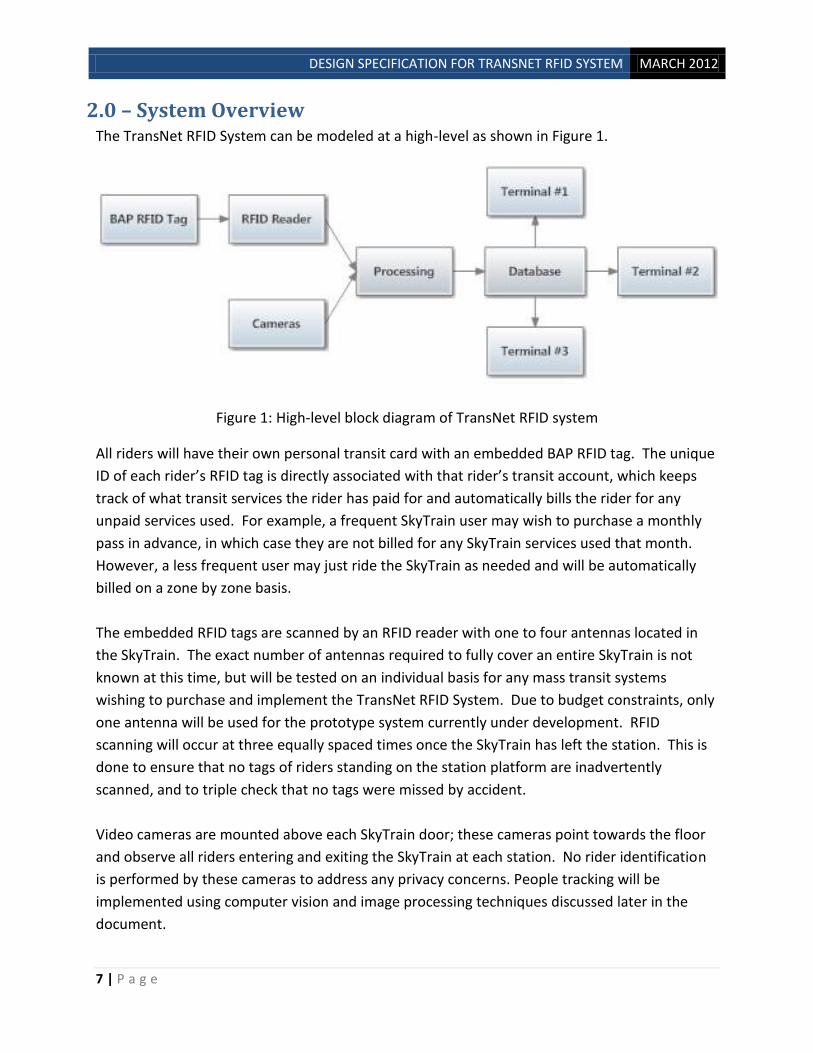
2.0 – System Overview The TransNet RFID System can be modeled at a high-level as shown in Figure 1.
Figure 1: High-level block diagram of TransNet RFID system
All riders will have their own personal transit card with an embedded BAP RFID tag. The unique
ID of each rider’s RFID tag is directly associated with that rider’s transit account, which keeps
track of what transit services the rider has paid for and automatically bills the rider for any
unpaid services used. For example, a frequent SkyTrain user may wish to purchase a monthly
pass in advance, in which case they are not billed for any SkyTrain services used that month.
However, a less frequent user may just ride the SkyTrain as needed and will be automatically
billed on a zone by zone basis.
The embedded RFID tags are scanned by an RFID reader with one to four antennas located in
the SkyTrain. The exact number of antennas required to fully cover an entire SkyTrain is not
known at this time, but will be tested on an individual basis for any mass transit systems
wishing to purchase and implement the TransNet RFID System. Due to budget constraints, only
one antenna will be used for the prototype system currently under development. RFID
scanning will occur at three equally spaced times once the SkyTrain has left the station. This is
done to ensure that no tags of riders standing on the station platform are inadvertently
scanned, and to triple check that no tags were missed by accident.
Video cameras are mounted above each SkyTrain door; these cameras point towards the floor
and observe all riders entering and exiting the SkyTrain at each station. No rider identification
is performed by these cameras to address any privacy concerns. People tracking will be
implemented using computer vision and image processing techniques discussed later in the
document.

DESIGN SPECIFICATION FOR TRANSNET RFID SYSTEM MARCH 2012
8 | P a g e
All of the scanned RFID data and the camera video footage are then sent through a wired
connection to a computer on board each SkyTrain. This computer compiles a list of all the
scanned RFID tags, along with the time of reading and what location the train is currently at;
the total number of tags is also computed. The footage from each camera is processed by
image processing software running on the computer which keeps a numerical count of the
number of riders entering and leaving the train at each station. A comparison between the
number of tags scanned and number of actual riders on the train is then performed. This data
can then be used by the transit company to target their fare evasion policing efforts as they see
fit. All of this information is then updated from the SkyTrain computer to a central database
over private Wi-Fi connection at each station.
The central database serves several important functions. Firstly, it allows any transit system
personnel at an authorized terminal to monitor the live transit data in real time. Secondly, it
routinely stores (configurable by the transit company) a snapshot of the current transit data
and stores it to disk. This allows the transit company to collect, analyze, and manipulate their
full transit data history for any desired research purpose, such as determining low or peak
usage times and adjusting the number of trains in service accordingly.
3.0 – RFID System Design
3.1 – RFID Reader TransNet has selected the Impinj Speedway R220 for its proof of concept system due to its
cheaper price than the R420. The R420 would be used for the actual SkyTrain implementation
due to having four channels for four antennas, one for each SkyTrain cart. The Speedway R420
is otherwise identical to or better than the R220, and meets all of the same functional
requirements; R420 can be safely interchanged anywhere R220 is written in this document.
The Speedway R220 is sufficiently small (19 x 17.5 x 3 cm) to be easily installed in a SkyTrain
with minimal modifications to the SkyTrain being necessary. It meets our environmental
requirements of being able to operate between -20 to 35oC and humidity levels of 43 to 99%.
The R220 meets the EPCglobal UHF Class 1 Gen 2 / ISO 18000-6C Air Interface Protocol. The
R220 is IEC IP52 certified for environmental sealing and Mil-Std-810G Certified for shock and
vibration. TransNet believes this sufficiently meets the requirements for the reader to be able
to operate in a moving SkyTrain. The R220 can be powered either through PoE or through a
standard 120 V outlet with an external power supply; whichever is easiest to implement on the
SkyTrain.

DESIGN SPECIFICATION FOR TRANSNET RFID SYSTEM MARCH 2012
9 | P a g e
Due to the R220’s high sensitivity (-82 dBm), it is ideal for use with BAP tags to enable reading
distances of greater than 10 meters, even when the tags are close to the human body. The
R220 can read tags at approximately 300 tags/second, which is sufficient to be able to poll an
entire SkyTrain in a sufficiently short period of time. Based on TransNet’s personal testing, the
R220 has never missed scanning a tag which has been placed inside its reading range.
3.2 – RFID Tags
BAP tags are vastly superior to regular passive tags in terms of maximum reading distance,
especially when the tags are placed in close proximity to humans or are not directly in the line
of sight of the reader. Active tags were not used due to their shorter battery life, increased
size, and should the battery die, the tag is unreadable, unlike BAP tags which act as a regular
passive tag if the battery dies.
Several different BAP tags were under consideration. This quickly became narrowed down to
PowerID’s PowerP tags and Essen’s Personna tags due to them being specifically designed to be
used on and near people (i.e. in pockets, bags, etc), their credit card form factor (85 x 54 x 1.5
mm for PowerP and 86 x 56 x 0.8 mm for Personna), read ranges of 10-20 meters, and battery
lifetimes of greater than two years. Both of these tags also operate at temperatures of -20 to
35oC and humidity levels of 43%-99%.
At this time the exact tag to be used is still undetermined. Talks with both companies are
underway and availability/price will be the final factors in determining which tags are
purchased.
4.0 – Database and Web Server Design
Overview
A database and web server will be created to communicate with computers aboard SkyTrains
and Transit Authorities (depicted in the figure below). This database will be used to store
information received from computers aboard trains and also provide statistical information to
transit officials such as determining low or peak usage times so that they may adjust the
number of trains in service.
Within the database, an account will be created for each pre-paid fare-card that is purchased
by passengers. The server will automatically deduct money from that account based on how
many fare zones the passenger has travelled during the day and what type of fare-card it is
(adult or concession).

DESIGN SPECIFICATION FOR TRANSNET RFID SYSTEM MARCH 2012
10 | P a g e
Figure 4.2.1: Overview of the communication protocols involved between clients and hosts.
Backend Server
The Backend server will communicate with computers aboard the SkyTrains. A reliable
communication protocol is required to communicate between server and client. Thus, we will
use a TCP/IP connection when sending and receiving packets. This protocol also provides error
detection, congestion control, and flow control which is also a requirement when sending data
that needs to be error-free. C++ will be used to program the Backend server because of its
widespread use, documentation, and extensive libraries. A text file will be sent from the train
computer to the server containing pertinent information. The following table describes the
information the text file will contain.
Table 4.2.1: Describes the data (text file) received by the backend server from the client
Sent Data Data type
Train ID Integer
Number of Tags Integer
Number of Persons Integer
Tag IDs detected Array of Strings
Using the data from the text file, the following algorithm will be implemented by our backend
server using C++.

DESIGN SPECIFICATION FOR TRANSNET RFID SYSTEM MARCH 2012
11 | P a g e
Figure 4.2.2: Algorithm Flow Chart that will be executed by the backend server.

DESIGN SPECIFICATION FOR TRANSNET RFID SYSTEM MARCH 2012
12 | P a g e
Whenever a fare evader is detected by the algorithm, the program will alert transit authorities
by flagging a variable in the database (next section). Once the program above has finished, we
will take the information in the text file and insert it into the database using SQL commands
such as SELECT and UPDATE which allow us to retrieve and update information in the database.
SQL was chosen because it’s widely used to manage information in databases.
Database Management System
The data in the database will be organized in a manner similar to the following diagram.
Figure 4.2.3: Overview of the database management system.
MySQL was chosen as a database management system because it’s the most widely relational
database software in the market and it is open source. As seen in the figure above, the
database is separated into three tables.
In the first table, TrainCatalogue, a high level view of all the trains currently in the system is
shown. It contains 6 columns which: uniquely identify the trains (TrainID), the previous location
of the trains (PreviousStation), their destination (NextStation), a time stamp of when the trains
last sent data to the server (RecentTimeStamp), the number of passengers
(NumberofPassengers), and the number of fare evaders detected by the security system
(NumberofFareEvaders).
In the second table, Trains, there are two fields: TrainID which was explained in the previous
paragraph and TagID. The TagID section uniquely identifies the RFID tag numbers detected on a
particular train.

DESIGN SPECIFICATION FOR TRANSNET RFID SYSTEM MARCH 2012
13 | P a g e
The third table, TagPersonalInfo, contains several fields which are filled out when the passenger
purchases the transit fare card. This personal information given to the transit authorities is
input in to the database by the system administrator (TransNet). It allows the transit authorities
to identify who is allowed to use fare cards so as to avoid several people using the same
monthly pass. TransNet understands that this may raise some privacy concerns, but data will be
kept confidential and will be erased as soon as the fare card is not used anymore. Moreover,
reliable and secure protocols will be used (TCP and SSL) to transmit any sensitive data.
Web Server
The figure below illustrates all the protocols that will be used to connect with different
components in the system, particularly the Apache Web Server. HTTP will be used to connect
the Web Server. This protocol was used because it can be used reliably and any web browser
can be used as the client.
Figure 4.2.4: Diagram of the Web Server and the connection protocols that will be used.
When the Backend receives information (via a TCP connection) from the computer aboard the
train, it will establish an HTTP connection to the Web Server which will allow it to modify the
SQL data. Note, that the Backend Server and Web Server are on the same computer.
Transit authority officials will also be able to connect to the Apache Web Server via a web
browser. The Web server will dynamically create web pages using PHP scripting languages and
display it to the web browser. PHP was used because it allows us to create a website that is
interactive and friendly to our users. The connection between the web server and browser will
be established via a Local Area Connection.
We will use a software package called WAMP which stands for “Windows Apache MySQL PHP”
to implement our web server and database because it’s open source, has well documented help
files, and is widely used throughout the internet.

DESIGN SPECIFICATION FOR TRANSNET RFID SYSTEM MARCH 2012
14 | P a g e
5.0 – Video Camera/Image Processing Design The video camera and associated image processing software used in this project will detect people entering and exiting the SkyTrain. A camera will be installed overlooking each train door. A counter will track movement of individuals entering/exiting through the train door by either incrementing or decrementing according to the flow of motion. A single person entering will be valued with a positive value of one and vice versa for those exiting. Moreover, if two individuals enter/exit at the same time, the counter will be incremented or decremented by a value of two according to the flow of motion. Initially, the counter will be initialized to a value of zero when the SkyTrain is put into service. In this manner, the counter will keep a numerical track of the number of individuals inside each SkyTrain. In developing the image processing software, it is assumed that no more than 2 people can enter/exit each train door at the same time.
In order to ensure the proper detection, a number of considerations are examined each with multiple requirements that are outlined below.
5.1 – Camera
Through testing with our image processing algorithm (outlined later), TransNet has determined
that camera’s with too great a resolution and/or too great of a frame rate result in excessive
image processing times. We have determined that a camera which captures at 15 FPS and
approximately 320 x 210 resolution offers a good balance between processing time and being
able to adequately track moving people. For the proof of concept we are using a cell phone
camera and do not plan on actually purchasing a camera. When the time comes to implement
on the SkyTrain, a cheap camera which meets the functional specifications and the above FPS
and resolution requirements will easily be able to be found.
5.2 – Processes
The processing involves two major components: Background Acquisition and People Detection. These processes are described below.
5.2.1 – Background Acquisition
Background acquisition process will first look at the presence of motion by looking at the difference between 2 consecutive frames. This difference will then be compared to a threshold and if the difference is greater than this threshold (presumably threshold value would corresponding to noise in the image), then motion will be detected. As long as motion is detected, the acquired images will not be used for the background set. Once still images (no motion in the image) have been acquired, the first five set of frames will be averaged (i.e. pixel by pixel) to obtain the background image under a specified time. The process will store this averaged background image as the reference frame and serve as a comparison for detection purposes. If the process is unable to acquire five set of background images under this time interval, it will terminate and use only images that were still (i.e. implying that we would have less than five still images at our disposal). In the scenario were no images were acquired (due to motion), previously stored background images are used. The purpose of this exercise is to

DESIGN SPECIFICATION FOR TRANSNET RFID SYSTEM MARCH 2012
15 | P a g e
obtain updated background reference images as previous reference frames may be outdated due to changes in the physical background (e.g. different lighting condition, dust, etc). Figure 5.2.1.1 below shows a flow chart of how this process will operate.
Figure 5.2.1.1 : Background acquisition process
5.2.2 – People Detection
Video frames beginning from when the image processing software is activated until the camera turns off or train doors close are processed. The image processing performed will count the number of people entering/exiting. As high processing time is required, current algorithms (i.e. computation time) cannot keep up with the camera frame rate, thus a real-time system cannot be realized. To overcome this issue, the camera’s video frames will be stored from the start of

DESIGN SPECIFICATION FOR TRANSNET RFID SYSTEM MARCH 2012
16 | P a g e
the process until its end into a buffer. A pipelined approach will be implemented where by a certain amount of data (i.e. frames) will be processed in concurrency of the recording; thus blocks of data will be read from buffer and processed and cycled towards the next batch. Using this manner, no strict processing time is required as long as all frames are processed before the train arrives at the next station. A detailed description of this process is given in subsequent sections and Figure 5.2.2.1 shows a flow chart below.

DESIGN SPECIFICATION FOR TRANSNET RFID SYSTEM MARCH 2012
17 | P a g e
Figure 5.2.2.1 : Flow chart of people detection algorithm

DESIGN SPECIFICATION FOR TRANSNET RFID SYSTEM MARCH 2012
18 | P a g e
5.3 – Camera Location
An important consideration is the location of the camera. In order to avoid occlusion problems from a large group of people, it was decided that the camera will be mounted in an overhead position which will remove the possibility of individuals obstructing one another with reference to the camera’s field of view.
Deciding on the actual location of the camera for implementation into the SkyTrain system is something that cannot truly be done in this prototype phase of the project. The area coverage from the camera’s FOV would have to be adjusted such that only people entering/exiting the train are accounted for while excluding others on the platform. Moreover, the camera FOV has to be such that easy identification is possible while eliminating the possibility of obstruction from an individual saturating the entire FOV of the camera.
Despite not being able to perform these crucial tests at this point, different plausible camera placements were considered and are outlined below.
5.3.1 – Camera Placement 1
The camera is placed directly on top of the doors looking down. For this camera placement, the camera will only be active when a train is fully stopped at a station and the doors are fully open. Once the camera is active, the background acquisition process will run and try to get a good background. Once this process terminates, the people detection process will run and start counting the people entering/exiting the SkyTrain. The main problem with this placement is that the SkyTrain door entrance is very thin. If the camera then only looked at this very thin space, the image processing software would most likely fail to properly detect people. It would then be required for the camera’s FOV to span a larger area which might include part of the inside of the SkyTrain and part of the SkyTrain station which could include people or parts of people that are not entering/exiting the SkyTrain. Techniques to handle this situation will have to be implemented into the image processing algorithm. In addition, because the background changes slightly for each station, the camera will need to acquire a new background image every time the train stops at a station and the doors open. Since most likely people will be in the camera’s FOV at this time, a good background image could be hard to acquire.
5.3.2 – Camera Placement 2
The camera is placed on the ceiling inside the SkyTrain looking towards the SkyTrain door entrance. The timing requirements for powering on the camera and running the 2 processes will be the same as that for camera placement 1. This camera placement however would not place the camera in an exact overhead position and could thus cause some potential occlusion problems. If someone is walking close behind another person, the image processing algorithm could also mistake these 2 people for 1 person. In addition, as for camera location 1, the camera will most likely see part of the SkyTrain station and part of the inside of the SkyTrain as well as the SkyTrain door entrance, causing the same problems described in camera location 1.

DESIGN SPECIFICATION FOR TRANSNET RFID SYSTEM MARCH 2012
19 | P a g e
5.3.3 – Camera Placement 3
The camera is placed on the ceiling of the SkyTrain station looking directly down towards the SkyTrain platform edge, bordering the tracks, marked with a yellow strip. For this camera placement, the camera will always be active and the people detection process will run when a train stops at a station. For this camera placement, there is no strict timing requirement for running the background acquisition process. It was observed that the SkyTrains always stop at exactly the same spot so that the cameras can be aligned to look down where the door entrances are and to where people will be walking in and out. Since only people entering/exiting will go through the yellow strip, this camera placement will exclude all other people standing by. A main problem with this camera placement is that there will most likely be people planning on boarding the SkyTrain standing on the platform edge as a train arrives. Techniques will need to be developed in the image processing algorithm to handle this situation. A major advantage of this camera placement over the others however, is that the camera can get a good background image at any time. Since people are not usually standing on the platform edge when there are no incoming trains, the camera can easily acquire a good background image. This means that the background acquisition process can be run at any time between trains stopping at a station. Thus for this camera placement, the background acquisition process will be run periodically in order to continually update the background. This camera placement also has the added advantage that all the image processing can be done on the SkyTrain stations rather than the SkyTrain, eliminating the need to install onboard processors. For this particular camera placement, the people detection process will count the net number of people that entered the SkyTrain. This number will be sent to the central server where it will be added to the number of people that were previously there.
Figure 5.3.3.1: Person walking under camera's FOV

DESIGN SPECIFICATION FOR TRANSNET RFID SYSTEM MARCH 2012
20 | P a g e
5.4 – Segmentation
Once an image has been acquired - a number of different steps are taken to segment, separate,
identify and perform a physical count. The following is a general description of the steps taken
for frames with motion detected objects.
Initially, conversion to binary is performed followed by process of erosion and dilation which
works to disconnect object that may be merged due to blurring or noise as outlined below.
Erosion is one of the two basic operators in the area of mathematical morphology, the other being
dilation. The basic effect of the operator on a binary image is to erode away the boundaries of regions of
foreground pixels (i.e. white pixels, typically) hence areas of foreground pixels shrink in size, and holes
within those areas become larger as shown below.
Figure 5.4.1: Erosion
Coupled with erosion is dilation that works to gradually enlarge the boundaries of regions of foreground
pixels. Thus areas of foreground pixels grow in size while holes within those regions become smaller as
shown in Figure 5.4.2.
Figure 5.4.2: Dilation

DESIGN SPECIFICATION FOR TRANSNET RFID SYSTEM MARCH 2012
21 | P a g e
In essence, erosion and dilation work to remove images that are weakly linked/merged
together and separate them. A second step after this process is to filter objects that do not
meet certain area threshold requirement to remove objects (other than actual people) which
could later affect our counting scheme..
5.5 – Blob Tracking
This section describes how the algorithm keeps track of blobs seen in consecutive frames so that it can determine whether each blob is entering or exiting.
5.5.1 – Blob Labeling
Once a good segmentation separating the foreground from the background is achieved the algorithm will then identify all the blobs that are present and give them a unique label. This is called connected component labeling. The algorithm does this by scanning the binary segmented image and checking which set foreground pixels are connected, based on 4-connectivity or 8-connectivity. Foreground pixels in the binary image will have a value of 1 while background pixels will have a value of 0. A blob that is 4-connected is a blob which has all its pixels connected horizontally or vertically while an 8-connected blob is a blob which has all its pixels connected horizontally, vertically, or diagonally.
Figure 5.5.1.1 : comparing 4-connectivity vs. 8-connectivity
If the blobs in Figure 3 were identified based on 4-connectivity, 2 blobs will be identified while if they were identified based on 8-connectivity, only 1 blob will be identified. For the purposes of this algorithm, it was found that 8-connectivity gave better results and this is the connectivity scheme used.

DESIGN SPECIFICATION FOR TRANSNET RFID SYSTEM MARCH 2012
22 | P a g e
Each identified blob is given a unique numeric label. These numeric values are stored in a matrix, the size of the image. The locations where these values are stored in the matrix correspond to the co-ordinates of the pixels each corresponding labeled blob encompasses. For the blobs in Figure 3 the matrix will look as shown in Figure 4 for blobs identified based on 4-connecivity.
Figure 5.5.1.2 : Labeled blobs
Here one blob is labeled with the numerical value of 1 while the other one is labeled with the
numerical value of 2.
Other, much more powerful techniques, for connected component labeling are available. These
techniques work with full coloured images or grey scale images rather than binary images and
look at pixel colour and intensity values for separating out blobs. These techniques perform
much better at separating out blobs than the technique used with binary images, and in particular,
they can separate 2 blobs that are adjacent to each other; something that could not happen with
binary images. Thus these techniques will be immensely helpful in avoiding merging blobs.
These techniques, however, are very complex and very hard and time consuming to implement.
Due to the severe time limitations of getting a prototype system finished, it was decided that the
much simpler method using binary images would be used. If time permits, an attempt will be
made at implementing these powerful techniques. In either case, the final fully functioning
system would have these techniques implemented into it.
5.5.2 – Extracting Blob Features
Once each blob and its corresponding pixel locations are identified and labeled, the algorithm will then extract certain features of each blob. The following is a list of features that the algorithm will use.
Bounding box corner co-ordinates

DESIGN SPECIFICATION FOR TRANSNET RFID SYSTEM MARCH 2012
23 | P a g e
Bounding box center co-ordinates
Bounding box width
Bounding box height
Area of blob (in terms of pixels)
Mean grey scale intensity value of blob
Histogram of RGB colours encompassing blob
direction blob is moving
These feature values will be normalized to fall in the range between 0 and 1 and will be stored in a vector.
5.5.3 – Blob Matching
Once features of each blob have been extracted, these features will be used to compare each blob in a current frame to every blob identified in the previous frame, whose features will have been stored, and a best match will be attained. The blob in the current frame will then be labeled with the label of the best matched blob in the previous frame. If a blob in a current frame however is largely different than any blob seen in the previous frame, this will be identified as a new blob and a completely new label will be applied to it. The purpose of this blob matching is so that the algorithm can keep track of which blob is which as they appear in new consecutive frames. This matching is crucial to the proper detection of the motion of a blob and to the decision of whether the blob is entering or exiting. Figure 5 below clarifies how this matching will work.
Figure 5.5.3.1 : Blob matching
The purpose of the virtual line will be described in a subsequent section. The matching that was done for blob 2 in Figure 5.5.3.1 will be done for every blob in the current frame. If a blob in the

DESIGN SPECIFICATION FOR TRANSNET RFID SYSTEM MARCH 2012
24 | P a g e
previous frame is matched to more than 1 blob in the current frame, the best match between these blobs will be found and then removed from both frames. The blobs that remain will then be re-matched and the process will repeat until there are no more multi-matches. Figure 5.5.3.2 below clarifies how this will be done.
Figure 5.5.3.2: Multimatched blobs
The best match is chosen based on the minimum Euclidian distance between each pair of feature
vectors.
This method takes a pair of feature vectors and gets the Euclidian distance between them using
the following formula
Here, Ei and Ej represent the 2 feature vectors corresponding to the pair of blobs and d is the
number of features that were extracted. The smaller the distance, the closer the 2 blobs match,
the minimum distance possible of course being 0.
Though more accurate methods for blob comparison and best matching are available, these
methods are rather complex and computationally expensive. This method was chosen based on

DESIGN SPECIFICATION FOR TRANSNET RFID SYSTEM MARCH 2012
25 | P a g e
its simplicity of implementation. Given more time, more complicated methods could be
implemented to improve the accuracy of the system.
An aspect that has not yet been decided upon is the proper handling of merging blobs. One
consideration has the algorithm first decide if a labeled blob is a merged blob or a single blob.
This can be done by looking at the area of the blob and seeing if exceeds a certain threshold. If it
does, the algorithm will then look at the previous frame to see which blobs were there in the area
of the possibly merged blob. If in the previous frame there were 2 blobs present that merged into
one there will be a reduction from 2 blobs to 1 blob. The algorithm can then know that these 2
blobs have merged into 1 and can treat this new merged blob as consisting of 2 people.
Otherwise it will treat it like any normal blob. This approach however is very highly prone to
errors. As a result, merging blobs will have to be avoided as much as possible by implementing a
good blob identifying technique as discussed in section 5.5.1
5.6 – Detecting Entering/Exiting Blobs
Once each blob in a current frame has been matched to a blob in the previous frame, the positions of these blobs in the 2 frames will be compared to a virtual line. If 1 particular blob is below a virtual line in the past frame and above it in the current frame, then a counter will be incremented by 1 to indicate that the blob has entered. If a blob is above the virtual line in the past frame and below it in the current frame, this counter will be decremented by 1 indicating that this blob has exited. If neither of these conditions happens for any blob, then the counter will not change. If a particular blob could not be matched, then this comparison will not be done for that blob.
The bounding box center is the feature that is used to indicate blob position. Another feature that could be used is bounding box corners.
The figures below show how this detection process works
Figure 5.6.1: Person in previous frame Figure 5.6.2: Person in previous frame

DESIGN SPECIFICATION FOR TRANSNET RFID SYSTEM MARCH 2012
26 | P a g e
Figure 5.6.3: Identified blob in previous frame Figure 5.6.4: Identified blob in current frame
The person in the above pictures has crossed the virtual line in going from one frame to the next and thus the counter will be incremented or decremented. It should be noted that for the figures above there is a difference of 10 frames between the current frame and the previous frame to show clarity.
6.0 - System Test Plan System Test Plan
This system test plan is designed to ensure stability and performance requirements are met.
This Test plan is subdivided into categories covering test cases for each module. Once each
module has demonstrated correct functionality, the prototype is build and the final system is
tested as a whole to illustrate seamless integration via different scenarios.
RFID Reader / RFID Tags
Ideally, we would like to read as many tags as possible in any given skytrain cart. Due to
distance constraints, we need to use multiple readers in each cart along with battery-assisted
RFID tags for better functionality and data. However, due to limited resources and time, we will
use 1 RFID reader in an average sized room along with a few RFID tags. For the following test
cases we assume each person has a passive RFDI tag on them
Task: Ensure correct data acquisition without motion
Steps: One person will remain motionless in the room to see if correct data is being read by the
reader
Task: Ensure correct data acquisition with motion

DESIGN SPECIFICATION FOR TRANSNET RFID SYSTEM MARCH 2012
27 | P a g e
Steps: the above test case is repeated while the person is in motion resulting in variation in
distance between the tags and the reader.
Task: To test RFID reader’s threshold
Steps: More people with RFID tags will be added to the room to test the threshold of the
reader
Camera/Video Processing
The purpose of this module is to determine the total number of people entering/exiting a
skytrain cart. This number will be used later to determine the number of fare evaders and the
people who haven’t paid. For the test cases below, we will use a standard doorway of a room
which can fit 2 people at most entering or exiting at the same time. The camera will be placed
directly above the doorway to detect motion.
Task: To detect one person entering/exiting
Steps: 1 person will walk through the doorway and the webcam should detect that person
entering. The camera should also flag that person as exiting when the person walks in the
opposite direction through the door way.
Task: To detect two people entering/exiting
Steps: The above test case is repeated but this time with two people entering/exiting through
the doorway at the same time where one passenger is located slightly behind the first. System
should be able to detect both people.
Task: To detect two people entering/exiting side-by-side
Steps: The above test case is repeated but this time with two people located side-by-side
entering/exiting through the doorway at the same time.
Task: To detect 1 person entering while another exits
Steps: Repeat the above test cases but this one with one person entering the doorway while
the other is exiting by moving in the opposite direction.
Task: To detect a person who stands in the middle of the doorway
Steps: One person will stand in the middle of the door way and then quickly moves one way or
another to simulate quick decisions made by riders during peak hours.

DESIGN SPECIFICATION FOR TRANSNET RFID SYSTEM MARCH 2012
28 | P a g e
Task: To detect people while one remains stationary
Steps: In this case, we have one person standing in the middle of the door way motionless
while another person is entering or exiting through the doorway.
Backend Server/Web Server
The purpose of this module is to receive, store, and validate incoming data sent from the
laptops stationed in each skytrain. Once the server has passed the following test cases
regarding security and reliability, it will be integrated in the overall system prototype.
Task: Establish connection using communication protocols in the transport and network layer
(TCP/IP).
Steps: We begin by attempting to establish a reliable and secure connection between the client host and server using TCP/IP using C++ programming language. Task: Data transmission of a file over the IP network to the backend server
Steps: The client (computer aboard the train) will start by sending a simple file that includes tag numbers detected, total number of people, the identification number of the train, and a time stamp. This file is divided into packets. The server must check for errors as it receives the packets. Task: Implement the Web Server and establish HTTP connection to the Backend Server. Steps: Use an Apache Web Server with PHP to implement the web server and connect to the backend server via a HTTP connection. Task: Insertion of data into database management system. Steps: The information received by the backend server will be inserted into the database management system which is implemented using MySQL in real time. Task: Use the Apache Web Server, MySQL, and PHP to dynamically create web pages for Transit authorities. Furthermore, once the server passes the simple tests mentioned above, it will be tested extensively for vulnerability in software and security of data transmission and to prevent hackers from intercepting data during transfer. Also, a graphical user interface (GUI) will be developed to display the information received on the server’s end and to make it user-friendly for the operators.

DESIGN SPECIFICATION FOR TRANSNET RFID SYSTEM MARCH 2012
29 | P a g e
Conclusion
This document outlines the design specification used to implement the Translink RFID System.
It discusses the individual components and design choices we have made in order to implement
this project and meet the functional requirements along with performance and stability in
mind. A detailed test plan is designed to improve the system by testing the components
individually, and the fully integrated system. A prototype of the fully-integrated system will be
available with an estimated date of April 5th, 2012.

DESIGN SPECIFICATION FOR TRANSNET RFID SYSTEM MARCH 2012
30 | P a g e
7.0 – References
[1] http://www.cbc.ca/news/canada/montreal/story/2008/04/21/qc-smartcards0421.html
[2]http://ubyssey.ca/news/TransLink-threatening-to-cancel-u-pass/
[3]http://www.vancourier.com/TransLink+beefs+security+after+FareSavers+theft/5917942/story
.html
[4] http://www.translink.ca/en/Be-Part-of-the-Plan/Electronic-Fare-Cards/FAQs.aspx
[5]http://www.cbc.ca/news/canada/british-columbia/story/2009/07/29/bc-heat-wave-
forecast.html
[6] http://www.ec.gc.ca/meteo-weather/default.asp?lang=En&n=6A4A3AC5-1
[7] http://weatherspark.com/averages/27858/Vancouver-British-Columbia-Canada
[8] http://www.impinj.com/Speedway_Revolution_UHF_RFID_Reader.aspx
[9] http://www.buyspeedwayrevolution.com/ImpinjRevolution.htm
[10] en.wikipedia.org/wiki/Climate_of_Vancouver
[11] http://www.cbc.ca/news/canada/british-columbia/story/2009/07/29/bc-heat-wave-
forecast.html
[12] R. Fisher, S. Perkins, A. Walker and E. Wolfart. Hypermedia Image Processing
Reference. [Online] http://homepages.inf.ed.ac.uk/rbf/HIPR2/connect.htm
[13] M. A. Ali, S. Indupalli and B. Boufama. Tracking Multiple People for Video Surveillance.
School of Computer Science, University of Windsor.
[Online] http://computer-vision.org/4security/pdf/windsor.pdf
[14] Damien LEFLOCH. Real-Time People Counting system using Video Camera. Master of
Computer Science, Image and Artificial Intelligence, 2007.
[Online] www.colorlab.no/content/.../file/Damien_Lefloch_Master_thesis.pdf
[15] R. Fisher, S. Perkins, A. Walker and E. Wolfart. Hypermedia Image Processing
Reference. [Online] http://homepages.inf.ed.ac.uk/rbf/HIPR2/label.htm