functional verification - cornell university
TRANSCRIPT

Functional Verification
Semiconductor Reuse Standard
IPMXDSRSFVX00001SRS V3.2

SRS V3.2 01 FEB 20052
© Freescale Semiconductor, Inc. 2005
Freescale reserves the right to make changes without further notice to any products herein to improve reliability, function ordesign. Freescale does not assume any liability arising out of the application or use of any product or circuit described herein;neither does it convey any license under its patent rights nor the rights of others. Freescale products are not designed, intended,or authorized for use as components in systems intended for surgical implant into the body, or other applications intended tosupport or sustain life, or for any other application in which the failure of the Freescale product could create a situation wherepersonal injury or death may occur. Should Buyer purchase or use Freescale products for any such unintended or unauthorizedapplication, Buyer shall indemnify and hold Freescale and its officers, employees, subsidiaries, affiliates, and distributorsharmless against all claims, costs, damages, and expenses, and reasonable attorney fees arising out of, directly or indirectly, anyclaim of personal injury or death associated with such unintended or unauthorized use, even if such claim alleges that Freescalewas negligent regarding the design or manufacture of the part. Freescale and and the stylized Freescale logo are registeredtrademarks of Freescale Semiconductor, Inc. Freescale Semiconductor, Inc. is an Equal Opportunity/Affirmative Action Employer.
Freescale Semiconductor
Revision History
Version Number Date Author Summary of Changes
2.0 06 DEC 1999 SoCDTRevision based on SRS development process. Detailed history contained in DWG records.
3.0 30 APR 2001SoC-IP
Design SystemsChange summary location:http://socdt.sps.mot.com/ddts/ddts_main
3.0.1 01 DEC 2001 SoC&IP Edit
3.0.2 15 MAR 2002 SoC&IP Replaced Motorola font batwing with batwing gif.
3.1 1 NOV 2002 SoC&IP Changed to reflect changes to SRS V3.1.
3.1.1 1 APR 2003 SoC&IPChanged to reflect changes to SRS V3.1.1; added eight new paragraph tags
3.1.1 3 OCT 2003 SoC&IPAdded new verification information, including Vera, Verilog, and CBV coding standards
3.2 01 FEB 2005 DEO
Added new verification information, including Vera, Verilog, and CBV coding standards.Included minor rule and guideline updates; added Testbench diagram; coverage guidelines changed to rules.Rearranged sections to have CBV next to ABV. Added new CBV guideline (G9.8.27). Updated System Verilog migration requirements.Added “Clocking” section, changes to response checkers section; added coverage object; added Transactors section
Semiconductor Reuse Standard
Table of Contents
Section 9 Functional Verification
9.1 Reference Information . . . . . . . . . . . . . . . . . . . . . . . . . . . . . . . . . . . . . . . . . . . . . . . . . .17
9.1.1 References. . . . . . . . . . . . . . . . . . . . . . . . . . . . . . . . . . . . . . . . . . . . . . . . . . . . . . . . .17
9.1.2 Terminology . . . . . . . . . . . . . . . . . . . . . . . . . . . . . . . . . . . . . . . . . . . . . . . . . . . . . . . .17
9.2 Coding for Verification . . . . . . . . . . . . . . . . . . . . . . . . . . . . . . . . . . . . . . . . . . . . . . . . . .20
9.2.1 General . . . . . . . . . . . . . . . . . . . . . . . . . . . . . . . . . . . . . . . . . . . . . . . . . . . . . . . . . . .21
9.2.2 Monitors . . . . . . . . . . . . . . . . . . . . . . . . . . . . . . . . . . . . . . . . . . . . . . . . . . . . . . . . . . .25
9.2.3 Drivers . . . . . . . . . . . . . . . . . . . . . . . . . . . . . . . . . . . . . . . . . . . . . . . . . . . . . . . . . . . .26
9.2.4 Responders . . . . . . . . . . . . . . . . . . . . . . . . . . . . . . . . . . . . . . . . . . . . . . . . . . . . . . . .27
9.2.5 Transactors . . . . . . . . . . . . . . . . . . . . . . . . . . . . . . . . . . . . . . . . . . . . . . . . . . . . . . . .28
9.2.6 Response Checkers. . . . . . . . . . . . . . . . . . . . . . . . . . . . . . . . . . . . . . . . . . . . . . . . . .29
9.3 Stimulus . . . . . . . . . . . . . . . . . . . . . . . . . . . . . . . . . . . . . . . . . . . . . . . . . . . . . . . . . . . . .29
9.4 Simulation Environment . . . . . . . . . . . . . . . . . . . . . . . . . . . . . . . . . . . . . . . . . . . . . . . . .32
9.5 Code and Functional Coverage . . . . . . . . . . . . . . . . . . . . . . . . . . . . . . . . . . . . . . . . . . .34
9.5.1 General . . . . . . . . . . . . . . . . . . . . . . . . . . . . . . . . . . . . . . . . . . . . . . . . . . . . . . . . . . .34
9.5.2 Code Coverage Metrics . . . . . . . . . . . . . . . . . . . . . . . . . . . . . . . . . . . . . . . . . . . . . . .35
9.5.3 Functional Coverage Metrics . . . . . . . . . . . . . . . . . . . . . . . . . . . . . . . . . . . . . . . . . . .35
9.6 Formal Logic Equivalence Checking . . . . . . . . . . . . . . . . . . . . . . . . . . . . . . . . . . . . . . .35
9.6.1 General . . . . . . . . . . . . . . . . . . . . . . . . . . . . . . . . . . . . . . . . . . . . . . . . . . . . . . . . . . .36
9.7 Assertion-Based Verification . . . . . . . . . . . . . . . . . . . . . . . . . . . . . . . . . . . . . . . . . . . . .36
9.7.1 Model Checking . . . . . . . . . . . . . . . . . . . . . . . . . . . . . . . . . . . . . . . . . . . . . . . . . . . . .37
9.8 CBV Language Coding Standards . . . . . . . . . . . . . . . . . . . . . . . . . . . . . . . . . . . . . . . . .37
9.8.1 Deliverables . . . . . . . . . . . . . . . . . . . . . . . . . . . . . . . . . . . . . . . . . . . . . . . . . . . . . . . .37
9.8.2 Reference Information . . . . . . . . . . . . . . . . . . . . . . . . . . . . . . . . . . . . . . . . . . . . . . . .38
9.8.3 Naming Conventions . . . . . . . . . . . . . . . . . . . . . . . . . . . . . . . . . . . . . . . . . . . . . . . . .38
9.8.4 Comments . . . . . . . . . . . . . . . . . . . . . . . . . . . . . . . . . . . . . . . . . . . . . . . . . . . . . . . . .43
9.8.5 Code Style . . . . . . . . . . . . . . . . . . . . . . . . . . . . . . . . . . . . . . . . . . . . . . . . . . . . . . . . .48
9.8.6 Module Partitioning and Reusability. . . . . . . . . . . . . . . . . . . . . . . . . . . . . . . . . . . . . .49
9.8.7 CBV Good Practices . . . . . . . . . . . . . . . . . . . . . . . . . . . . . . . . . . . . . . . . . . . . . . . . .51
9.8.8 General Coding Techniques . . . . . . . . . . . . . . . . . . . . . . . . . . . . . . . . . . . . . . . . . . .51
9.9 Verilog Specific Coding Standards . . . . . . . . . . . . . . . . . . . . . . . . . . . . . . . . . . . . . . . . .54
9.9.1 Symbolic Constants . . . . . . . . . . . . . . . . . . . . . . . . . . . . . . . . . . . . . . . . . . . . . . . . . .55
SRS V3.2 01 FEB 2005 1Freescale Semiconductor
Semiconductor Reuse Standard
9.9.2 Routines . . . . . . . . . . . . . . . . . . . . . . . . . . . . . . . . . . . . . . . . . . . . . . . . . . . . . . . . . . .56
9.9.3 Signal Access. . . . . . . . . . . . . . . . . . . . . . . . . . . . . . . . . . . . . . . . . . . . . . . . . . . . . . .56
9.10 Vera Specific Coding Standards. . . . . . . . . . . . . . . . . . . . . . . . . . . . . . . . . . . . . . . . . . .57
9.10.1 Coding . . . . . . . . . . . . . . . . . . . . . . . . . . . . . . . . . . . . . . . . . . . . . . . . . . . . . . . . . . . .58
9.10.2 Components. . . . . . . . . . . . . . . . . . . . . . . . . . . . . . . . . . . . . . . . . . . . . . . . . . . . . . . .69
9.10.3 HDL Interface . . . . . . . . . . . . . . . . . . . . . . . . . . . . . . . . . . . . . . . . . . . . . . . . . . . . . . .70
9.10.4 Files . . . . . . . . . . . . . . . . . . . . . . . . . . . . . . . . . . . . . . . . . . . . . . . . . . . . . . . . . . . . . .72
9.10.5 Command Line Options . . . . . . . . . . . . . . . . . . . . . . . . . . . . . . . . . . . . . . . . . . . . . . .72
9.11 Vera to System Verilog/Native Testbench Coding Standards . . . . . . . . . . . . . . . . . . . .72
9.11.1 Unsupported NTB Features . . . . . . . . . . . . . . . . . . . . . . . . . . . . . . . . . . . . . . . . . . . .73
9.11.2 Defined Types . . . . . . . . . . . . . . . . . . . . . . . . . . . . . . . . . . . . . . . . . . . . . . . . . . . . . .73
9.11.3 Expressions . . . . . . . . . . . . . . . . . . . . . . . . . . . . . . . . . . . . . . . . . . . . . . . . . . . . . . . .73
9.11.4 Interface . . . . . . . . . . . . . . . . . . . . . . . . . . . . . . . . . . . . . . . . . . . . . . . . . . . . . . . . . . .74
9.11.5 Procedures and Methods . . . . . . . . . . . . . . . . . . . . . . . . . . . . . . . . . . . . . . . . . . . . . .74
9.11.6 I/O . . . . . . . . . . . . . . . . . . . . . . . . . . . . . . . . . . . . . . . . . . . . . . . . . . . . . . . . . . . . . . .75
9.11.7 Synchronization . . . . . . . . . . . . . . . . . . . . . . . . . . . . . . . . . . . . . . . . . . . . . . . . . . . . .75
9.11.8 Miscellaneous . . . . . . . . . . . . . . . . . . . . . . . . . . . . . . . . . . . . . . . . . . . . . . . . . . . . . .76
SRS V3.2 01 FEB 20052 Freescale Semiconductor

Semiconductor Reuse Standard
List of Figures
Figure 9-1 Testbench Architecture . . . . . . . . . . . . . . . . . . . . . . . . . . . . . . . . . . . . . . . . . . . .20
Figure 9-2 File Header . . . . . . . . . . . . . . . . . . . . . . . . . . . . . . . . . . . . . . . . . . . . . . . . . . . . .31
Figure 9-3 CBV File Header . . . . . . . . . . . . . . . . . . . . . . . . . . . . . . . . . . . . . . . . . . . . . . . . .44
Figure 9-4 CBV Functions, User-Defined Primitives and Tasks Header. . . . . . . . . . . . . . . .46
SRS V3.2 01 FEB 2005 1Freescale Semiconductor

Semiconductor Reuse Standard
SRS V3.2 01 FEB 20052 Freescale Semiconductor
Semiconductor Reuse Standard
List of Tables
Table 9-1 Rule Source References . . . . . . . . . . . . . . . . . . . . . . . . . . . . . . . . . . . . . . . . . . . .58
Table 9-2 Naming Types . . . . . . . . . . . . . . . . . . . . . . . . . . . . . . . . . . . . . . . . . . . . . . . . . . . .68
SRS V3.2 01 FEB 2005 1Freescale Semiconductor

Semiconductor Reuse Standard
SRS V3.2 01 FEB 20052 Freescale Semiconductor

Semiconductor Reuse Standard
Rule and Guideline Reference
Reference Information
Coding for Verification
R 9.2.1 Comments must describe the intent and purpose of the codeR 9.2.2 Communication to verification components must occur without advancing simulation timeR 9.2.3 Derived clocks must be generated within the same simulator time stepR 9.2.4 Verification components must assume a known default configurationR 9.2.5 Memory control statements must be placed in configuration filesR 9.2.6 A driver must be used to reset the VCR 9.2.7 A common routine (e.g. task or function) must be used to display simulation messagesR 9.2.8 [DEBUG|INFO| WARN! | ERROR!|FATAL!] @<sim_time> <INSTANCE>: <comment> format must
be usedG 9.2.9 It is recommended that displayed comments be limited to 80 charactersR 9.2.10 The testbench must complete execution with a Pass or Fail indicationR 9.2.11 A passing test must end with a return code of zero if numeric return codes are usedR 9.2.12 The testbench must have a single termination pointR 9.2.13 The testbench must provide the ability to control the maximum time a simulation runsR 9.2.14 Hang detection must be provided.R 9.2.15 Monitors must monitor only one interfaceR 9.2.16 Monitors must not drive design inputsR 9.2.17 Monitors must check and/or observe all transactions on the interfaceR 9.2.18 Monitors must be self-contained.R 9.2.19 Monitors must not determine if a transaction should be happening on an interfaceR 9.2.20 Monitors must only sample signals that will be preserved after synthesisR 9.2.21 Monitors must be reusable by all VC that connect to the interfaceR 9.2.22 Unrecognized interface activity must be flagged as an errorR 9.2.23 Monitors must be capable of being enabled and disabledG 9.2.24 It is recommended to keep monitor output to a minimum in the default configurationG 9.2.25 It is recommended that monitors provide abstractions of interface activityR 9.2.26 Drivers must be the only component that stimulate the VC interface signalsR 9.2.27 Drivers must stimulate only one interfaceR 9.2.28 Drivers must only drive boundary signalsR 9.2.29 Drivers must drive all transactions the interface can performR 9.2.30 Drivers must generate an error for unsupported commands.R 9.2.31 Global signals must not be used to configure driversR 9.2.32 Drivers must not check the interface protocolR 9.2.33 A driver must not assign values to an interface signal more than once in the same timestepG 9.2.34 Inputs should only be driven for the duration which they are validR 9.2.35 Memory responder model arrays dimensions must be parameterizedG 9.2.36 It is recommended that memory within responders be implemented as sparse arraysG 9.2.37 RAM can only contain initial content, if the content can be loaded via an appropriate interfaceG 9.2.38 Errors should be detected at the point of failure
SRS V3.2 01 FEB 2005 1Freescale Semiconductor

Semiconductor Reuse Standard
R 9.2.39 Transactors must operate in zero timeR 9.2.40 Transactors must accept a Driver connection upon instantiationR 9.2.41 Transactors must not connect to a signal interfaceR 9.2.42 The response checker must be configured independent of the VCG 9.2.43 Response checkers should not connect to the VCG 9.2.44 Response checkers should publish coverage events
Stimulus
R 9.3.1 Random stimulus must come with a response and coverage checking mechanismR 9.3.2 The stimulus source code must document the features that it targetsR 9.3.3 The header documentation must match the stimulusR 9.3.4 The header must contain the content shown in Figure 9-2.R 9.3.5 Stimulus that depends on another VC must be partitioned separatelyG 9.3.6 It is recommended that VC-level stimulus be partitioned based upon functionalityG 9.3.7 It is recommended that the same stimulus be run at the VC and SoC level
Simulation Environment
R 9.4.1 Simulator errors and warnings must be detectedR 9.4.2 Multiple VC or SoC view simulations must be supportedG 9.4.3 The regression environment should allow stimulus files to be placed into hierarchal subdirectories
within a single parent directoryR 9.4.4 Allow stimulus to be simulated with different configurations and generate unique output filesR 9.4.5 Locating regression runs in any directory on the network must be supportedR 9.4.6 The verification environment must be recreatableR 9.4.7 Every regression test must be able to be run stand-aloneR 9.4.8 Regression tests must not rely on the results of former regression test runR 9.4.9 The regression environment must support running stimulus with a single submissionR 9.4.10 Simulation output files must be named consistently across simulation environmentsR 9.4.11 The testbench and a subset of stimulus must operate on gate level modelsR 9.4.12 Hard VC models must operate with back annotationG 9.4.13 The simulation environment should support zero and unit delay gate-level regressions
Code and Functional Coverage
R 9.5.1 Only VC code must be instrumented for code coverageG 9.5.2 It is recommended to run coverage on all configurations that will be manufacturedR 9.5.3 Statement coverage must achieve 100%R 9.5.4 Branch coverage must achieve 100%R 9.5.5 Condition coverage must achieve 100%R 9.5.6 FSM state transition coverage must achieve 100%R 9.5.7 Functional coverage must achieve 100%.
Formal Logic Equivalence Checking
R 9.6.1 Soft VC must be verifiable by a logic equivalence checking toolR 9.6.2 Bus contention must not existR 9.6.3 Three-state buses must be proven to not have contentionR 9.6.4 Switch level extraction must include appropriate scripts and data
Assertion-Based Verification
SRS V3.2 01 FEB 20052 Freescale Semiconductor

Semiconductor Reuse Standard
R 9.7.1 The model checking environment must be reproducibleG 9.7.2 It is recommended that model checking be performed on all control-intensive VC codeG 9.7.3 It is recommended that an assume/guarantee method of model checking be supported
CBV Language Coding Standards
R 9.8.1 At most one module per fileR 9.8.2 File naming conventionsR 9.8.3 Alphanumeric and underscores allowable character setR 9.8.4 First character of a name is a letterR 9.8.5 No escaped namesR 9.8.6 Separate names composed of several words with underscoresR 9.8.7 Consistent spelling and style of signal namesR 9.8.8 CBV names are equivalent to documentation namesR 9.8.9 Names representing constants are upper caseR 9.8.10 Identifiers other than symbolic constants are lower caseR 9.8.11 Use meaningful namesR 9.8.12 CBV, Verilog, and Verilog-AMS keywords not allowedR 9.8.13 Global text macros include module nameR 9.8.14 Active low signal names end in _bR 9.8.15 Clock signal names end in _clkG 9.8.16 High-impedance signal names end in _zG 9.8.17 State machine next state names end in _next or _nsG 9.8.18 Test mode signal names end in _testG 9.8.19 Var variable names end with <signal-name>_D<delay-number> when they sample <signal-name>,
<delay-number> cycles ago.G 9.8.20 Multiple suffix signal name orderG 9.8.21 Var variable names start with v_G 9.8.22 Assign variable names start with a_G 9.8.23 Local variable names start with l_G 9.8.24 Variable names length does not exceed 32 charactersG 9.8.25 Avoid uncommon abbreviationsG 9.8.26 Document abbreviations and additional naming conventionsG 9.8.27 Names should be selected carefully according to CBV scoping rules.R 9.8.28 Each file must contain a file headerR 9.8.29 Use file header boundary tags (+FHDR & -FHDR)R 9.8.30 Include file nameR 9.8.31 Include point of contact informationR 9.8.32 Include a release historyR 9.8.33 Include a keyword sectionR 9.8.34 Include a purpose sectionR 9.8.35 Include a parameter descriptionR 9.8.36 Additional constructs in file use a headerR 9.8.37 Use construct header boundary tags (+HDR & -HDR)R 9.8.38 Include construct nameR 9.8.39 Include construct typeR 9.8.40 Include a purpose section
SRS V3.2 01 FEB 2005 3Freescale Semiconductor

Semiconductor Reuse Standard
R 9.8.41 Include a parameter descriptionR 9.8.42 Other header documentationR 9.8.43 Comment functional sectionsR 9.8.44 Document unusual or non-obvious implementationsR 9.8.45 Delete old codeR 9.8.46 Comment template instantiationsG 9.8.47 Comment variable declarationsG 9.8.48 Use ‘///’ for line coverage commentsG 9.8.49 Comment end and endcase statementsG 9.8.50 Use comments liberallyR 9.8.51 Write code in a tabular formatG 9.8.52 Use consistent code indentation with spacesR 9.8.53 One CBV statement per lineG 9.8.54 Line length not to exceed 80 charactersR 9.8.55 Use templates to allow binding to any Verilog instanceR 9.8.56 Use templates for writing generic tasks and functions.R 9.8.57 Use templates ports for passing DUT signal names to the CBV code.R 9.8.58 Bus sizes of standard protocols should be template parametersR 9.8.59 Use tasks that are parameterized for common functionality sequencesR 9.8.60 Use a recursive task for repetitive sequences.R 9.8.61 Use functions that are parameterized for common combinational logicR 9.8.62 Combine multiple CBV files using a single file which uses the ‘include construct to include the CBV
filesR 9.8.63 Do not add path information when using the ‘include constructR 9.8.64 Create a file named cbv_init.cbv which will define ‘ifdef guards for all other CBV filesG 9.8.65 Avoid using internal design signalsR 9.8.66 Do not use the “if +(0 to *)” construct as a root statement within the main begin/end blockR 9.8.67 Use high level data types when possible.R 9.8.68 Use CBV_INIT for initializing var variablesR 9.8.69 Expression in condition must be a 1-bit valueR 9.8.70 Use consistent ordering of bus bitsR 9.8.71 Do not assign signals to xG 9.8.72 Use parameters instead of text macros for symbolic constantsR 9.8.73 Text macros must not be redefinedG 9.8.74 Preserve relationships between constantsR 9.8.75 Use text macros for base addressesR 9.8.76 Use base + offset for address generationG 9.8.77 Use text macros for register field positions and valuesG 9.8.78 Use text macros for signal hierarchy pathsR 9.8.79 Limit ‘ifdef nesting to three levelsR 9.8.80 Operand sizes must matchG 9.8.81 Use parentheses in complex equationsG 9.8.82 Use functional statements when writing complex combinational logic
Verilog Specific Coding Standards
R 9.9.1 Synthesizable and behavioral code must be partitioned in separate files
SRS V3.2 01 FEB 20054 Freescale Semiconductor
Semiconductor Reuse Standard
R 9.9.2 Unless variables are used globally, local declarations must be in named code blocksR 9.9.3 The default parameter settings must specify a verified implementationR 9.9.4 Parameters must be setable from the simulator command lineG 9.9.5 It is recommended that address offsets be specified by definesG 9.9.6 It is recommended that register offset names end with “_OFFSET”G 9.9.7 It is recommended that the base address names end with “_BASE”G 9.9.8 It is recommended that defines be used for frequently used valuesR 9.9.9 All VC-specific routine names must be lower caseR 9.9.10 All VC-specific routines must be preceded at least two unique charactersG 9.9.11 It is recommended that the disabling of routines occurs internallyG 9.9.12 It is recommended that routines be disabled from a single locationR 9.9.13 Reference to internal signals must be via text macrosR 9.9.14 Internal signals referenced must be listed in a single locationR 9.9.15 Internal signals referenced must be preserved through synthesisG 9.9.16 It is recommended that signals be referenced at the VC boundaryG 9.9.17 It is recommended that internal signals should not be forced
Vera Specific Coding Standards
R 9.10.1 Do not use System Verilog keywords for Vera identifiersR 9.10.2 [CS - page 11, VW p4-6] Use only // for comments, do not use /* */R 9.10.3 [CS - page 11] Delete unused codeG 9.10.4 [CS - page 12] A line must contain only one statementG 9.10.5 [CV - page4] Opening and closing braces must be indented to the same level and on their own lineG 9.10.6 [CV - page4] Use a consistent number of spaces to indent codeG 9.10.7 [CS - page 11] Comparison operators must have white space before and after the operatorG 9.10.8 [CS - page 12] List only one argument per line if the line with all the arguments exceeds 80 charac-
tersG 9.10.9 [CS - page 12] Lines should not exceed 80 charactersR 9.10.10 [TB-CvE] Do not use the “delay” taskR 9.10.11 [A - 134]Always use soft expects rather than hard expectsR 9.10.12 [A - 449] Do not rely on thread orderingR 9.10.13 [A - 182] Do not use “suspend_thread”R 9.10.14 [VR - slide 46] Only use integers for looping constructsR 9.10.15 [KD] Do not use global variablesR 9.10.16 [CV - page18] All waveform data storage must be turned off by defaultR 9.10.17 [A - 154] Always set the id parameter to zero when allocating regions, mailboxes, and semaphoresG 9.10.18 [KD] Always set the count equal to one on region, semaphore, and mailbox memory allocationsR 9.10.19 Only allocate mailboxes, semaphores, and regions at the class levelG 9.10.20 [VR - slide 46] Value change alerts (VCA) should be avoidedG 9.10.21 [VR - slide 46] Do not use arithmetic operators on vectors larger than 32 bitsG 9.10.22 [VW - page 7-25] Do not use “wait_var()”G 9.10.23 [KD] If a thread within a fork is surrounded by braces, then all threads within the fork must use themG 9.10.24 [VW - page 7-21] Pass shadow vars to child threads when the value changes outside the scopeG 9.10.25 [CV - page2] A file should not contain more than one class definitionG 9.10.26 [CS - page 6] Defines, Local, Public, and Protected class members should be in separately labeled
sections of the codeR 9.10.27 Declare virtual methods at each level of hierarchy
SRS V3.2 01 FEB 2005 5Freescale Semiconductor

Semiconductor Reuse Standard
R 9.10.28 Do not implement methods in-line in class declarationsR 9.10.29 [CV - page2] #defines and global enums must use all capital letters and the group name as a prefixR 9.10.30 [A-page 288] Always code numeric literals as defines or enumsR 9.10.31 [A - 202] Objects that will not be reused should be de-allocated after useR 9.10.32 [VC - slide 4] Variable and data member names must start with a lower case letterG 9.10.33 Hex numbers should be lower case and padded with a underscores every 4 or 8 charactersR 9.10.34 Comment blocks for Functions and Task headers must include a Function/Task, Inputs, Outputs,
and Description sectionsG 9.10.35 All debug messages should be surrounded by compile time switches that allow the code to be re-
movedG 9.10.36 Coding constructs which go into the Vera global name space should be uniqueG 9.10.37 Classes, objects and files should be named <Project/Group Initials><Protocol/Description><Type>G 9.10.38 Interfaces should be named <protocol>_<type>_if<_x>G 9.10.39 [VC - slide 4] The first letter of each word in a class name must be capitalized, do not use under-
scoresG 9.10.40 [CS - page 6] All class, interface, port, and bind file names must match the class, interface, port,
and bind name, including caseG 9.10.41 [Other] Never include the version number in a file nameR 9.10.42 [VC - slide 5] Use Vera recommended file extensionsG 9.10.43 [A - p134] It is recommended to use blocking drives instead of non-blocking drivesR 9.10.44 [CV - page5] Stimulus must be generated outside the driver, monitor, and response checkersR 9.10.45 Intra-monitor communication should not trap() using SPS eventsR 9.10.46 [CV - page4] Use virtual ports to group and reference portsR 9.10.47 [VW - page 3-16] Do not reference signal values within equationsR 9.10.48 [VR - slide 46] Limit signals in the interface file to those that are sampled and drivenR 9.10.49 [TB-CvE] Do not use the “async” attribute on inputs or outputsR 9.10.50 [VW - page 3-35] Always drive on the positive clock edge using a skew of +1R 9.10.51 [VW - page 3-35] Always sample on the positive clock edge using a skew of -1R 9.10.52 [TB-CvE] Only identify functional clocks as the input clock to Vera codeG 9.10.53 [CV - page16] Verification IP should not depend on the System ClockR 9.10.54 [CV - page6] Verification components must not depend on the vera program fileR 9.10.55 [CS - page 5] “.vrh” files must not be delivered with verification IPG 9.10.56 [VR - slide 46] Use the “-alim 0” switch to turn off global variable propagation for VeraG 9.10.57 Use -Hnu or -hnu to generate new header files with -C if needed
Vera to System Verilog/Native Testbench Coding Standards
G 9.11.1 Do not use Pack/Unpack/CRCR 9.11.2 Do not use regionR 9.11.3 Do not assume integer is a 2-state variable or 4-state variableR 9.11.4 Use “int” when a 2-state variable is neededR 9.11.5 Use reg for all 4-state bits and bit-vectorsR 9.11.6 Do not use the &~ operatorR 9.11.7 Do not use the bit reverse (><) operatorR 9.11.8 Do not place functions with side effects in condition comparisonsR 9.11.9 Do not use non-integral concatenationR 9.11.10 Do not use variable-width part selectsR 9.11.11 Ensure conditional operator decision expression does not contain or return ‘x’
SRS V3.2 01 FEB 20056 Freescale Semiconductor
Semiconductor Reuse Standard
R 9.11.12 Do not assume one or all branches of ternary operators executeR 9.11.13 Use = = = in an expect comparisonsR 9.11.14 Do not rely on initial drive of X or ZR 9.11.15 Do not use blocking functionsR 9.11.16 Do not use default argument orderingR 9.11.17 Do not use blocking constructs in new()R 9.11.18 Create user versions of copy, compare, and print methods for classesR 9.11.19 Restrict printf(), sprintf(), and fprint() to Verilog write statement format specifiers. Do not use %i, %x,
%p, %v, or %_.G 9.11.20 Do not use psprintf()R 9.11.21 Do not use more format specifiers than arguments in printf(), sprintf(), or fprint() statementsR 9.11.22 Do not rely on thread ordering or suspend_thread()R 9.11.23 Do not use Sync with orderR 9.11.24 Do not use the trigger() modes ON, OFF, or HandshakeR 9.11.25 Do not use timeoutR 9.11.26 Do not use mailbox_get with CHECKR 9.11.27 Do not use mailbox_send(), mailbox_receive()R 9.11.28 Do not use the vera final report for script processingR 9.11.29 Do not use Vera UDF functionsR 9.11.30 Do not use urand48()R 9.11.31 Use a utility function to process command arguments
SRS V3.2 01 FEB 2005 7Freescale Semiconductor

Semiconductor Reuse Standard
SRS V3.2 01 FEB 20058 Freescale Semiconductor
Semiconductor Reuse Standard
Section 9 Functional Verification
This document presents the Semiconductor Reuse Standard (SRS) for functional verification. Functionalverification is the activity of determining whether a design is logically correct. Functional verification testsare used to determine whether the virtual component (VC) and SoC models behave according to their func-tional specification.This standard addresses simulation, emulation, and formal verification. Simulation is the process of imi-tating the VC operation in software prior to manufacturing. Simulation is typically performed using anHDL simulator loaded with the stimulus, a model of the VC, and a testbench which is composed of drivers,monitors, response checkers, coverage objects, control code, and so on. Emulation is similar to simulation,but is accelerated by loading selected synthesizable components of VC and/or testbench into special hard-ware. Formal verification is the mathematical method proving that a design meets certain properties (mod-el checking), or that two representations are logically equivalent (equivalency checking).The intent of this section is to define standard design practices in the verification areas listed above to en-able reuse. Reuse of verification data is a critical element of rapid integration systems based on reusable IP.
9.1 Reference Information
9.1.1 References
The following reference was used to develop the standard and may be referenced in this section:[1] Virtual Socket Interface Alliance (http://www.vsi.org), Taxonomy of Functional Verification for
Virtual Component Development and Integration Standard Version 1, Released January, 2001.
[2] Accellera SystemVerilog Technical Committees (http://www.eda.org/sv), SystemVerilog 3.1a Language Reference Manual, released May, 2004.
9.1.2 Terminology
Asserted - A discrete signal is in AN active logic state.
• An active low signal is asserted when it is logic-level zero.
• An active high signal is asserted when it is logic-level one.Assertion - A statement made about the proper functioning of a logic circuit. Black box model - Abstract model of a VC consisting only of the port list, port declarations, and any inputconstraints that are assumed by the VC. It is based on a behavioral model providing the same functionalityon the interfaces as the final implementation. The model focuses on the functional specification, not on theimplementation. Branch coverage - Type of code coverage that determines which branches in the RTL source code havebeen taken during simulation.Centralized routine - Centralized routine is one that is commonly used by VC, testbench, and stimulus.It is a global routine.Clear - To establish logic-level zero on a bit or bits.Code block - The block statements are a means of grouping two or more statements together so that theyact syntactically like a single statement. There are two types of blocks in Verilog HDL:
SRS V3.2 01 FEB 2005 1Freescale Semiconductor

Semiconductor Reuse Standard
• Sequential block (also called begin-end block)
• Parallel block (also called fork-join block)Code coverage - Metric that measures coverage by reporting the parts of the RTL source code that havebeen simulated. Types of code coverage include statement, branch, condition, and toggle coverage.Compiled stimulus - C, assembly, or other language higher than a binary representation that is compiledinto a binary.Condition coverage - Type of code coverage that examines the subexpressions in condition statements todetermine which values of those subexpressions caused higher-level expressions to be true or false duringsimulation.Configuration - Collection of set up values applied to the configurable VC or verification code.Constraint - Boolean expression, usually in terms of design inputs, that the design assumes is always true.For logic checking, the existence of constraints implies that the two designs are allowed to be different forthose input values that do not satisfy the constraints. Likewise for mux checking, the existence of con-straints implies that the muxes are allowed to violate one-hotness for those inputs that are not satisfied bythe constraints. In functional verification involving sequential behaviors, the existence of constraints im-plies that the design is allowed to violate its functional obligations at and after application of inputs valuesthat do not satisfy the constraints.Coverage Object - An object-oriented testbench component that contains code for capturing functionalcoverage information. In Vera, a coverage object can be created by adding a coverage_group to an existingcomponent definition (i.e., existing class definition such as a monitor or response checker) or to a classthat is dedicated to capture functional coverage information.Deliverables - VC deliverables are a set of files that make up a design. They are provided by the virtualcomponent creator. Deliverables are assigned a unique identifier that consists of a letter followed by anumber. A complete description of the SRS deliverables can be found in documentIPMXDSRSDEL00001, Semiconductor Reuse Standard: VC Block Deliverables.Driver - A piece of code implementing tasks/functions/methods that causes pin-wiggling on a signal in-terface.Emulation operation mode - Specific type of master mode operation where ports of the SoC are emulatedand all primary pin functions are enabled. An external port replacement unit is supported.FSM coverage - Finite State Machine coverage. Metric that measures coverage by reporting which states,transitions, and/or input stimulus of an FSM have been simulated.Guideline - A guideline is a “recommended” practice that enhances rapid SoC design, integration, andproduction, reduces the need to modify IP deliverables, and increases maintainability.High-level array - Memory array represented by a software model or using behavioral HDL code (i.e., astatic register set).HLVL - High-Level Verification Language. Programming language used to write stimulus, and possiblydrivers/monitors, to verify hardware designs.Logic checking (also equivalence checking) - Use of formal mathematical methods to determine if theboolean functions of two designs are the same; typically performed automatically using a software pro-gram.Logic-level one - Voltage that corresponds to Boolean true (1) state.Logic-level zero - Voltage that corresponds to Boolean false (0) state.Low-level array - Array that most closely matches how the array will be implemented in silicon (e.g.,netlist).LSB - Least significant bit or bits.
SRS V3.2 01 FEB 20052 Freescale Semiconductor

Semiconductor Reuse Standard
MSB - Most significant bit or bits.Master mode - Mode in which the processor executes code from either internal or external memory. Monitor - A stand-alone, external piece of code that observes a specific protocol. It is always active anddetects transactions generated by, or applied to, the particular SoC or VC being monitored.Mux-checking (also one-hot checking) - Use of formal mathematical methods to determine if thethree-state multiplexors in a design all exhibit the property that one and only one enable is active at a time;typically performed automatically using a software program.Negated (or deasserted) - A discrete signal is in AN inactive logic state.
• An Active low is negated (deasserted) when it is logic-level one.
• An Active high signal is negated (deasserted) when it is logic-level zero. Pin - External physical connectionProperties - These are metadata properties that are a variable which is assigned a value. Values are uniqueto each VC but the property names are common to all VC blocks. Properties are also referred to as “Meta-data Properties.” Properties are also used in equations to determine if a rule is applicable to a deliverable.If the equation holds true, the rule applies to the deliverables.Regression - Running verification tools (such as simulations) in different contexts (such as different stim-ulus or backannotation timings) on the same model together with a mechanism to establish a pass/fail sta-tus for each run.Regression environment - Mechanism used to gather, compile, and run the testbench and stimulus files.Rule - A rule is a “required” practice that enables rapid SoC design, integration, and production, eliminatesthe need to modify IP deliverables, and supports maintainability. Set - To establish logic-level one on a bit or bits.Signal - Electronic construct whose state or changes in state convey information. Simulation - Process of applying a stimulus pattern to a software model that propagates the effect of inputstimulus changes as if the model was the actual device. The software model allows for various kinds ofmonitoring, probing and debugging tools to be run in conjunction with the simulation.Slave mode - Mode in which processor bus is directly controlled by a bus driver. At the SoC level, thisrequires the SoC to support an external bus interface (EBI) or other means to access the bus from the out-side.Specification coverage - Metric that measures coverage by reporting how many factual attributes in thespecification have been demonstrated to be true during simulation. Statement coverage - Type of code coverage that determines which executable statements in the RTLsource code have been executed during simulation.Stimulus - Definition for a specific set of state changes (e.g., transactions) to be applied to the VC (i.e.,device under test) through a suitable testbench and drivers/monitors. May or may not also specify con-structs to analyze response values generated by the VC.Stub model - Model for a design block that has the same module name and port list, and behaves like areal block in its inactive state (i.e., internal signals could be tied or fed through). Used as a placeholderwhen the design block’s functionality is not required but the top-level netlist is not to be changed.System-level clock speed - Primary operating frequency of the main core or bus master within the SoC.Testbench - Verification-specific constructs that provide the glue between the device under test (i.e., VC),driver, monitors, and stimulus. See document IPMXDSRSDEL00001, Semiconductor Reuse Standard:VC Block Deliverables for a complete description of the testbench components.Test mode - Mode in which special factory test features are enabled.Toggle coverage - Type of code coverage that checks that each node in VC changes polarity (toggles) dur-
SRS V3.2 01 FEB 2005 3Freescale Semiconductor

Semiconductor Reuse Standard
ing simulation and so is not stuck at one level.Transaction - An abstract representation of an atomic part (e.g., a read cycle) of a protocol that is support-ed by a specific interface (e.g., the IP Interface).VC response checker - Behavior model that ensures the VC is operating properly. It monitors the VC andgenerates errors or warnings when the VC does not behave according to its specification. It verifies thatoperations should be happening in a VC or on one of its interfaces.Vector - Single unit of stimulus and response. It specifies stimulus by assigning a 0, 1, or Z to each inputand bidirectional pin, and it specifies response by assigning a 0, 1, Z, or X to each output and bidirectionalpin. Contention must be avoided on bidirectional pins by conforming to the following constraints: If thepin is stimulated with 0 or 1, its expected response must be specified as X. If the expected response of thepin is 0 or 1, it must be stimulated with Z.
9.2 Coding for Verification
The goal of this section is to describe the standards for VC and system-level testbenches. The followingrules and guidelines define a testbench architecture that consists of standardized interfaces between com-ponents. Figure 9-1 shows the recommended testbench architecture.
Figure 9-1 Testbench Architecture
• Monitor - Observes and checks DUV interface protocol and abstracts signal transitions into events that are published for other testbench components.
• Driver - Drives transactions onto the signal interface based on commands received from the transactor.
• Transactors - Translates and coordinates sending commands to drivers from stimulus.
DUV1
Events Events
DriverB
Coverage
Response Checker
Transactor DriverAStimulusA Responder
MonitorA MonitorB
SRS V3.2 01 FEB 20054 Freescale Semiconductor
Semiconductor Reuse Standard
• Stimulus - Creates and issues commands to transactors.
• Responder - Subscribes to events from monitors and uses drivers to initiate appropriate transactions in response to events
• Coverage - Collect coverage metrics
• Response Checker - Checks DUV behavior.
9.2.1 General
R 9.2.1 Comments must describe the intent and purpose of the code
The intent and purpose of the code needs to be conveyed not simply describing what the code does. Therefore, under-standing the functionality and not the implementation should be the primary focus.
bad
// Increment counter
rx_addr_ptr = rx_addr_ptr + 1;
good
// Increment address pointing to next available location in receive buffer
rx_addr_ptr = rx_addr_ptr + 1;
Deliverables: V1, V2,V3,V4,V5,V6Properties: (NewIP==’True’)
R 9.2.2 Communication to verification components must occur without advancing simulation time
The testbench sequencing interface to the driver, monitor, and behavioral interfaces must communicate back and forth in zero simulation time. Use of #0 in Verilog is not allowed, this statement should be worked around by structuring the code so it flows with the sequence of events and makes specific handshakes.
Reason: Components may consume simulation but the communication must occur without advancing simulation so that all components can be interacted with during the same simulation time. Synthesizable and emulation-friendly VC.
Deliverables: V1,V2,V3,V4,V7,V14,V15
9.2.1.1 Clocking
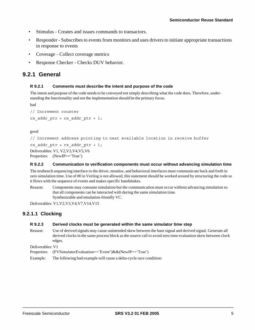
R 9.2.3 Derived clocks must be generated within the same simulator time step
Reason: Use of derived signals may cause unintended skew between the base signal and derived signal. Generate all derived clocks in the same process block as the source call to avoid zero time evaluation skew between clock edges.
Deliverables: V1Properties: (FVSimulatorEvaluation==’Event’)&&(NewIP==’True’)
Example: The following bad example will cause a delta-cycle race condition:
SRS V3.2 01 FEB 2005 5Freescale Semiconductor
Semiconductor Reuse Standard
Example: The following good example will not cause a delta-cycle race condition. First Verilog aligns on the delta edge of the base_clk blocking assignment. Once there, the two additional blocking clock assignments (fast_clk and slow_clk) are done in the same delta cycle.
Note: Only fast_clk or slow_clk should be used by design or the test bench. base_clk is used for clock generation only.
9.2.1.2 Testbench Configuration
The following rules and guidelines standardize the methods for setting configurations within verificationcomponents such as the testbench, drivers, and monitors. For example, a VC may have a specific bootmode setting that is configured by an external driver. The driver value may be set by reading settings froma configuration file or from stimulus commands.
R 9.2.4 Verification components must assume a known default configuration
Verification components must assume a known, well documented default configuration.
Reason: Eases the work for the integrator to find and set the configuration values during SOC integration.
Deliverables: V1,V2,V3,V4,V5,V7,V14Properties: (NewIP=='True')
reg fast_clk;reg slow_clk;
initialbegin fast_clk = 0; slow_clk = 0;end
forever #50 fast_clk = ~fast_clk;
always @(posedge fast_clk)begin slow_clk = ~slow_clk;end
reg base_clk;reg fast_clk;reg slow_clk;
initialbegin base_clk = 0; fast_clk = 0; slow_clk = 0;end
forever #50 base_clk = ~base_clk;
always @(base_clk)begin fast_clk = base_clk; if (base_clk) slow_clk = ~slow_clk;end
SRS V3.2 01 FEB 20056 Freescale Semiconductor
Semiconductor Reuse Standard
R 9.2.5 Memory control statements must be placed in configuration files
The configuration file contains mode settings for testbench components.
Reason: Provides flexibility to verify any memory configurations.
Example: Memory wait states that are can be parameterized.
Deliverables: V1,V14Properties: (NewIP=='True')
9.2.1.3 VC Reset
All stimulus needs a standard means of resetting and initializing the system.
R 9.2.6 A driver must be used to reset the VC
The command driven by the driver may initiate the reset sequence.
Reason: This allows for portability and code reuse.
Deliverables: V1Properties: (NewIP=='True')
9.2.1.4 Messages
This section contains rules and guidelines for how errors, warnings, and informational messages are to beissued during simulation. The goal is to provide a uniform messaging behavior to aid in script writing,readability, and portability.
R 9.2.7 A common routine (e.g. task or function) must be used to display simulation messages
Reason: Using common routines to display messages ensures a uniform output format and simplifies both debug and script writing. A single display routine also allows a single point of maintenance for the log file names.
Deliverables: V1,V2,V3,V4,V5,V7,V15Properties: (NewIP=='True')
R 9.2.8 [DEBUG|INFO| WARN! | ERROR!|FATAL!] @<sim_time> <INSTANCE>: <comment> format must be used
Sim_time is a count of the number of positive clock edges from time equals zero. It can be used to correlate messages in the log file to signal changes in a wave form viewer. Sim_time is not the same as $time because this is dependent on the simulator setting (i.e., tick definition in Verilog). When reporting an error during a simulation, the word ERROR! (case sensitive) must be used. When reporting less important issues, the word WARN! (case sensitive) must be used. The nature of the error or warning must also be indicated. This will include a description of the cause that created the error or warning, along with all applicable data for debugging the issue. The source instance name must be exactly one string and the colon must exactly follow this string (no blank between the INSTANCE and the colon). This provides the ability to automatically parse log files. The following are guidelines for using each of the error messages types:
FATAL -- An unrecoverable failure has occurred on the testbench. If such a scenario occurred in Si, the chip would either freeze, or be completely unpredictable. Also, used for bugs or conditions in the testbench which makes it impossible to continue (a bad pointer for example).
ERROR -- An error in functional performance has occurred. DUV works, protocols are adhered to, but the results are wrong. May be used to report problems in the testbench.
WARN -- Reports a problem which the DUV or the testbench can recover from. In small quantities, WARNs are okay and demonstrate the robustness of the DUV. In large quantities, WARN messages probably indicate that the DUV was designed wrong for the given application
INFO -- Display useful information about the state of the DUV or testbench. If used at all, should only be used to confirm correct behavior of DUV and testbench. Since INFO messages clog up log files, use only when necessary.
SRS V3.2 01 FEB 2005 7Freescale Semiconductor

Semiconductor Reuse Standard
DEBUG -- Used for debugging the testbench itself. Once the testbench is stable, these messages should not be used to convey information to the user. Also used to report problems or state of the Verification Base Classes or Tools themselves. These messages shall not be used to by Verification engineers to convey information about the DUV or the testbench. These messages shall only be turned on when a bug is suspected in the Verification Base Classes or Tools.
Example: The string “MY_VC” is the point of origin in the following message: ERROR! @ 780 MY_VC: Unexpected Bus Abort
Deliverables: V1,V2,V3,V4,V5,V7,V15
G 9.2.9 It is recommended that displayed comments be limited to 80 characters
All display comments in a stimulus should be limited to 80 characters. The only exception to this guideline is for path names.
Reason: Limiting the comment to 80 characters improves readability by preventing word wrapping.
Exception: Displaying the scope of a signal. For example, “top.testbench.interfacemodel.vc1.signalA” should not be part of the 80 character limit.
Exception: Displaying a directory path name. The testbench may display the path to configuration or stimulusfiles for example.
Deliverables: V1,V2,V3,V4,V5,V7,V15Properties: (NewIP=='True')
9.2.1.5 Termination
All testbenches must be terminated by a standard mechanism. This will ensure that the VC user can easilydetermine if the verification passed or failed without any detailed knowledge of the verification environ-ment or the stimulus.
R 9.2.10 The testbench must complete execution with a Pass or Fail indication
Pass and fail must be mutually exclusive. If a test does not pass, it must indicate failure. Time-outs are a failure. Case or if statements must be complete to indicate if a test passes or fails. There must be no branches that allow the test to finish without indicating pass or fail.
Reason: Parsing scripts may not notice failures.
Deliverables: V1
R 9.2.11 A passing test must end with a return code of zero if numeric return codes are used
Reason: Automation scripts can detect failing tests via nonzero return codes. There must be no branches that allow the test to finish without indicating pass or fail.
Deliverables: V7
R 9.2.12 The testbench must have a single termination point
A single statement in the testbench must be the source of the call that terminates the simulation.
Reason: Centralizes maintenance on one block of code for termination and Error/Warning message logging. Also allows a central location to delay termination if additional context is required.
Deliverables: V1
R 9.2.13 The testbench must provide the ability to control the maximum time a simulation runs
Timeout control must be provided to set an upper limit for the time a simulation can run. If the timeout period is reached, the testcase immediately terminate with an error message.
Reason: All tests must terminate. In the event of a deadlock situation (i.e., a feedback loop required for stimulus continuation does not occur), the testcase will never complete and simulation cycles will be unnecessarily wasted.
Deliverables: V1
SRS V3.2 01 FEB 20058 Freescale Semiconductor

Semiconductor Reuse Standard
R 9.2.14 Hang detection must be provided.
Hang detection must be provided for all transactions where timing variations are allowed in the protocol. This should result terminating the testcase with an error message
Reason: All transactions on an interface must end. In the event of a deadlock situation (i.e., a feedback loop required for stimulus continuation does not occur), the hung transaction will prevent the simulation from completing and simulation cycles will be unnecessarily wasted.
Deliverables: V1
9.2.2 Monitors
This section will define standard coding practice for VC monitors used in functional verification.
R 9.2.15 Monitors must monitor only one interface
The single monitor may encapsulate multiple sections of code or monitors as required.Internal drivers are removed as the VC is integrated in an SoC environment but there should still be a single monitor for the interface. All checking at this point will come from the stimulus and original VC monitor.
Reason: This makes the testbench more modular and reusable. This rule does not quantify the number of monitors required.
Deliverables: V3Properties: (NewIP=='True')
R 9.2.16 Monitors must not drive design inputs
Monitors must only listen and monitor design and testbench interface signals.
Reason: Drivers and other testbench components (e.g., clocking code) must do all signal driving to provide a consistent method for driving inputs. This provides the ability to reuse the monitor when the interface is being driven by other components.
Deliverables: V3
R 9.2.17 Monitors must check and/or observe all transactions on the interface
Reason: The monitor must be able to check transactions by the driver or system-level test stimulus. This enables monitoring of all interface activity. This will also enable development of stimulus that are based on events rather than timing.
Deliverables: V3
R 9.2.18 Monitors must be self-contained.
Monitors must not rely on other code such as a driver, behavioral, configuration management software, the run-time envi-ronment, or configuration registers within the VC. Parameters must be passed into the monitor for configuration so it may run on its own.
Reason: This makes the code portable without reliance on other parts of the design, environment, or test code.
Deliverables: V3
R 9.2.19 Monitors must not determine if a transaction should be happening on an interface
Monitors are intended only to check for correct operation of the transactions on the interface.
Reason: Determining if a transaction should happen on an interface must be left to the test stimulus and/or VC response checker.
Deliverables: V3Properties: (NewIP=='True')
R 9.2.20 Monitors must only sample signals that will be preserved after synthesis
Monitors must not reference internal signals that will not be present in all netlist types (i.e., RTL vs. Gate).
SRS V3.2 01 FEB 2005 9Freescale Semiconductor

Semiconductor Reuse Standard
Reason: Internal signals may not be present after synthesis and the monitor will not be reusable.
Deliverables: V3
R 9.2.21 Monitors must be reusable by all VC that connect to the interface
As the VC is integrated into a multi-unit or system-on-a-chip environment, the monitors must be reusable “as-is” to check for violations on the interface to the VC.
Reason: This allows portability of a monitor into the system-on-a-chip environment and reduces design duplication. System level testbench inherits all the interface checking of the lower-level design blocks and VC. This ensures there are no system level errors introduced.
Deliverables: V3
R 9.2.22 Unrecognized interface activity must be flagged as an error
Reason: This provides a capability to watch for erroneous interface activity, or activities, that violate a given interface protocol as well as function that monitor may not support
Deliverables: V3
R 9.2.23 Monitors must be capable of being enabled and disabled
Reason: This is important for reusing the VC on a SoC. On SoC designs the pads often have more than one function-ality (multiplexed I/O), and the functionality will be selected by primary pins and/or internal registers. In addition, scan testing may need to disable monitors so that errors are not reported during scan operations.
Deliverables: V3
G 9.2.24 It is recommended to keep monitor output to a minimum in the default configuration
Monitor output should be kept to the minimum in the default configuration. Too much debug information can make the log files difficult to read. Verbosity settings may be provided, the minimum output setting should be the default. Verbosity settings are required to be documented if used (see Documentation Standards).
Reason: Speed up simulation and ease of debug. In addition, reduces output file size (an issue when disk space becomes limited.
Deliverables: V3Properties: (NewIP=='True')
G 9.2.25 It is recommended that monitors provide abstractions of interface activity
Monitors must be used to identify information on the interface and report bus activities to the testbench.
Reason: The testbench and/or test stimulus may rely on an independent monitor to verify that a transaction has occurred. The abstraction may be used to coordinate and sequence downstream stimulus.
Example: A bus monitor may report all stores to a certain address range that occurs on the system bus.
Deliverables: V3
9.2.3 Drivers
This section defines standard coding practice for VC drivers used in functional verification. Drivers mayrespond and drive the interface of the VC by accepting commands in the stimulus or events from monitors.The drivers may also be stand-alone elements. Stand-alone drivers are reusable without dependencies onthe testbench and stimulus control.
R 9.2.26 Drivers must be the only component that stimulate the VC interface signals
Drivers must understand how to execute complete transactions with the VC and therefore must contain the intelligence required to interact with the VC.
Reason: This make the verification components more modular and re-usable.
Deliverables: V1, V2
SRS V3.2 01 FEB 200510 Freescale Semiconductor

Semiconductor Reuse Standard
R 9.2.27 Drivers must stimulate only one interface
The drivers must stimulate only one interface into the VC. An interface is defined as a set of signals that implements a specific protocol.
Reason: It makes the design more modular and allows drivers to be reusable.
Deliverables: V2
R 9.2.28 Drivers must only drive boundary signals
Reason: Enables reuse at the VC and SoC level without modification or dependencies.
Exception: Global halt and resume signals. Global signals may be used for the purpose of halting drivers for DFT testing. Users may want to halt a driver, scan out the chip, do a scan in, and then resume functional operation.
Deliverables: V2
R 9.2.29 Drivers must drive all transactions the interface can perform
Reason: This enables other virtual components that have the same interface to reuse the driver without modification.
Deliverables: V2
R 9.2.30 Drivers must generate an error for unsupported commands.
Reason: This provides a mechanism to help detect unsupported functionalities.
Deliverables: V2Properties: (NewIP=='True')
R 9.2.31 Global signals must not be used to configure drivers
The use of global signals must be prohibited.
Reason: Code will be portable.
Exception: Global signals may be used to control the driver for design for test testing (e.g., a global signal may be driven from a JTAG module to stop the driver from sending transactions so that the VC may be scanned in the middle of a test case).
Deliverables: V2Properties: (NewIP=='True')
R 9.2.32 Drivers must not check the interface protocol
Reason: Protocol checking must be handled by monitors.
Deliverables: V2Properties: (NewIP=='True')
R 9.2.33 A driver must not assign values to an interface signal more than once in the same timestep
Reason: Avoids glitches in simulation. Aids in understanding code.
Deliverables: V2
G 9.2.34 Inputs should only be driven for the duration which they are valid
Reason: Leaving inputs at a constant value during invalid times would not detect cases where the VC under verifica-tion does not meet timing requirements. If a signal is not valid during a given time/cycle, drive that value to a nonvalid value during this period, and ensure that the value does not propagate through the VC under verifica-tion causing failures. Three-state signals should be turned off during nonvalid cycle times.
Deliverables: V2
9.2.4 Responders
This section will define the standard coding practice for VC responders used in functional verification.Memory array models are verification components that represent the functionality of internal and external
SRS V3.2 01 FEB 2005 11Freescale Semiconductor

Semiconductor Reuse Standard
memory circuits. Behavioral models are used instead of implementation-oriented models to speed up sim-ulation. The models are reusable VC. Reusability is enhanced by following the rules and guidelines in thissection.
R 9.2.35 Memory responder model arrays dimensions must be parameterized
Reason: Parameters for array size and dimension makes arrays more portable.
Deliverables: V14Properties: (NewIP=='True')
G 9.2.36 It is recommended that memory within responders be implemented as sparse arrays
Memory space restrictions may be established for modeling purposes and to speed simulation.
Reason: Smaller memory size speeds up simulation.
Deliverables: V14Properties: (NewIP=='True')
G 9.2.37 RAM can only contain initial content, if the content can be loaded via an appropriate inter-face
Reason: The stimulus function may not be portable to real silicon.
Deliverables: V14
G 9.2.38 Errors should be detected at the point of failure
Identification of the failures must be at the point of failure and not post processed as often as possible.
Reason: Reduces the time spent debugging failures.
Example: Using assertions and references detect errors closer to the point of origin during the simulation.
Deliverables: V14Properties: (NewIP=='True')
9.2.5 Transactors
This section will define the Transactor. Transactors insulate stimulus objects from the low-level details of a Driver’s interface. Multiple stimulus objects can share access to a single Driver or multiple Drivers using references to a single Transactor. Transactors allow high-level transactions to be remapped to lower-level transactions, transparent to the stimulus object. Transactors solve problems associated with Stimulus reuse that occur when binding specific Drivers to a stimulus object.
R 9.2.39 Transactors must operate in zero time
Reason: Transactors are used to model transaction-level behavior. Signal-level behavior is modeled in the Driver.
Deliverables: V15
R 9.2.40 Transactors must accept a Driver connection upon instantiation
Reason: There may be multiple instances of a Driver and the transaction code should not have to be modified just to connect to a different instance of a Driver.
Deliverables: V15
R 9.2.41 Transactors must not connect to a signal interface
Reason: Signal-level behavior is modeled in the Driver.
Deliverables: V15
SRS V3.2 01 FEB 200512 Freescale Semiconductor
Semiconductor Reuse Standard
9.2.6 Response Checkers
This section will define the Response Checker, a testbench component that ensures the requests cominginto a VC are responded to correctly. Block-level response checkers verify that operations coming out ofa VC should be happening and that the results are correct.
R 9.2.42 The response checker must be configured independent of the VC
Block-level response checkers must be configured via the testbench, stimulus, and/or monitors. Configuration of the checker must not occur based on the internal VC state. Checkers may be used to preload states into the VC.
Reason: Problems with the VC configuration may be masked. This provides independent verification of the VC operation and configuration mechanism.
Deliverables: V4Properties: (NewIP=='True')
G 9.2.43 Response checkers should not connect to the VC
Response checkers should interface with existing testbench components such as monitors.
Reason: This makes the response checker more maintainable. If the interface changes, only the monitor is required to change, and the interaction with the response checker may be preserved as-is.
Deliverables: V4Properties: (NewIP=='True')
G 9.2.44 Response checkers should publish coverage events
Reason: Response checkers often contain complex response calculation code that can shared to report interesting coverage events.
Deliverables: V4
9.3 Stimulus
This section outlines rules that apply to stimulus regardless of stimulus form. Stimulus could be slavemode or master mode, random or directed, depending on the context. Random simulation is used for ex-ercising boundary cases of the VC. It is achieved by generating pseudo-random transactions for stimulus.Randomness can be either in content (e.g., random data in a write transaction), appearance (e.g., randomlychoose between a read and a write transaction), or both.Constraints are written to specify the range of allowed random transactions. Tools are used to randomlygenerate transaction within the allowed range. Probability and weighting schemes are used to bias the ran-dom selection of transactions.Properly coded stimulus can produce stimulus that are portable and easier to maintain. The following stan-dards and guidelines are for verification source code.Partitioning can impact the ease with which a model can be adapted to an application. Patterns must bepartitioned to facilitate portability to different chips. Proper partitioning allows the easy omission of stim-ulus whose functions and/or pins are not being utilized on a particular chip. Patterns are able to be used“as is” without modifications. This directly reduces stimulus debug time.
R 9.3.1 Random stimulus must come with a response and coverage checking mechanism
A model or a prediction function must be provided to verify the random behavior of the VC. Coverage must be provided to prove the that intended operation has occurred under the intended conditions. As opposed to nonrandom testbenches where expected results can be embedded within the stimulus, random behaviors need a more general way to describe the expected results.
SRS V3.2 01 FEB 2005 13Freescale Semiconductor

Semiconductor Reuse Standard
Reason: Random stimulus generation is most valuable when it’s known to exercises the functions of interested and ensure that the functions are operating correctly.
Deliverables: V1Properties: (FVRandom=='True')
R 9.3.2 The stimulus source code must document the features that it targets
The stimulus source code must contain comments, in addition to the header, within the context of the stimulus documenting the tests that occur in the code flow. Functional stimulus should be well commented or otherwise self-documenting so that the pattern source clearly indicates the function being verified, sufficient so that the failure can be related back to the location of the defect in RTL. Random stimulus should include a description of the constraints used to exercise the features.
Reason: This provides the means by which the VC consumer can relate a functional pattern failure back to the design feature which was targeted.
Deliverables: V7
R 9.3.3 The header documentation must match the stimulus
Reason: This will ensure the proper test strategy and verification methodology is being followed.
Deliverables: V7
SRS V3.2 01 FEB 200514 Freescale Semiconductor
Semiconductor Reuse Standard
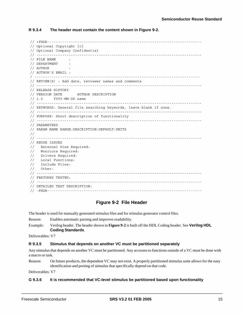
R 9.3.4 The header must contain the content shown in Figure 9-2.
Figure 9-2 File Header
The header is used for manually generated stimulus files and for stimulus generator control files.
Reason: Enables automatic parsing and improves readability.
Example: Verilog header. The header shown in Figure 9-2 is built off the HDL Coding header. See Verilog HDL Coding Standards.
Deliverables: V7
R 9.3.5 Stimulus that depends on another VC must be partitioned separately
Any stimulus that depends on another VC must be partitioned. Any accesses to functions outside of a VC must be done with a macro or task.
Reason: On future products, the dependent VC may not exist. A properly partitioned stimulus suite allows for the easy identification and porting of stimulus that specifically depend on that code.
Deliverables: V7
G 9.3.6 It is recommended that VC-level stimulus be partitioned based upon functionality
// +FHDR------------------------------------------------------------------------// Optional Copyright {c}// Optional Company Confidential// -----------------------------------------------------------------------------// FILE NAME :// DEPARTMENT :// AUTHOR :// AUTHOR’S EMAIL :/ -----------------------------------------------------------------------------// REVIEW(S) : Add date, reviewer names and comments// -----------------------------------------------------------------------------// RELEASE HISTORY// VERSION DATE AUTHOR DESCRIPTION// 1.0 YYYY-MM-DD name// -----------------------------------------------------------------------------// KEYWORDS: General file searching keywords, leave blank if none.// -----------------------------------------------------------------------------// PURPOSE: Short description of functionality// -----------------------------------------------------------------------------// PARAMETERS// PARAM NAME RANGE:DESCRIPTION:DEFAULT:UNITS//// -----------------------------------------------------------------------------// REUSE ISSUES// External Pins Required:// Monitors Required:// Drivers Required:// Local Functions:// Include Files:// Other:// -----------------------------------------------------------------------------// FEATURES TESTED:// -----------------------------------------------------------------------------// DETAILED TEST DESCRIPTION:// -FHDR------------------------------------------------------------------------
SRS V3.2 01 FEB 2005 15Freescale Semiconductor

Semiconductor Reuse Standard
Individual stimulus should be partitioned into separate files based upon functional test cases. Partitioning should be done to avoid redundancy and ensure proper ordering of tests.
Reason: Stimulus checking via a small number of test cases allows faster identification of problems in the failing stimulus and allows easier generation of stimulus.
Example: The test order should exercise the read and write capability of a register prior to testing the function of a register.
Deliverables: V7
G 9.3.7 It is recommended that the same stimulus be run at the VC and SoC level
Reason: To minimize the number of stimulus and debug effort, it is recommended that the stimulus be coded using parameters and other techniques to allow expected register data values, synchronization of bus transactions with external pin activity, etc., to adjust to delay introduced at different levels of the device hierarchy. For example, when executing stimulus at the VC level, VC accesses may be back-to-back. However, when the stimulus is applied at the SoC level, there may be one to three wait states incurred on each VC access.
Deliverables: V7Properties: (NewIP=='True')
9.4 Simulation Environment
This section lists requirements for the regression environment to enable verification reuse. Regressionstandards are essential to ensure that stimulus can be run in an automated manner. This section providesstandards and guidelines on running simulations using VC that is checked out of the IP Repository. A stan-dard represents a practice that must be supported by the simulation environment. Regression guidelinesare the most desirable approach to particular issues with running simulations, but are not mandatory forthe simulation environment to support them.Efficiently running regressions is an important verification task. Regression scripts may be written to au-tomate the task of running regressions and gathering results. Regressions must be allowed to be batchedoff to several machines on the network to take advantage of machine resources. In addition, the ability toquickly analyze the results will enhance the productivity of the verification person.Regressions may be run at the VC or SoC level. It is essential that the regression environment support bothlevels of regression testing. The regression environment must also provide the flexibility to run regressionsusing various testbench configurations, various VC or SoC views, running all types of stimulus, and com-pare current simulation results against reference results.
R 9.4.1 Simulator errors and warnings must be detected
Post-processing scripts must take into account simulator messages (i.e., compilation, invocation errors, etc.).
Reason: Ensures that stimulus was properly executed.
Deliverables: V8
R 9.4.2 Multiple VC or SoC view simulations must be supported
The regression environment must allow different combinations of VC or SoC views to be used on a per run basis. These are to be based off a basic simulation configuration file according to the configuration required to simulate the stimulus.
Reason: Regressions may need to be run using different VC or SoC views, such as behavioral, RTL, gate, black box models, or gate with back-annotated timing.
Deliverables: V8
G 9.4.3 The regression environment should allow stimulus files to be placed into hierarchal subdi-rectories within a single parent directory
SRS V3.2 01 FEB 200516 Freescale Semiconductor

Semiconductor Reuse Standard
Patterns that use different VC configurations may need to be placed in separate directories to allow the regression environ-ment to change simulation configurations on the fly.
Reason: This will allow the regression environment to support the different requirements for each stimulus to simulate correctly.
Deliverables: V8
R 9.4.4 Allow stimulus to be simulated with different configurations and generate unique output files
The regression environment must allow the same stimulus to be simulated using different configurations and generate a unique output file name so that the original simulation results are not overwritten.
Reason: This will allow the regression to simulate a stimulus with one or more configurations and not overwrite the previous simulation results.
Deliverables: V8
R 9.4.5 Locating regression runs in any directory on the network must be supported
The regression environment must allow the regression runs to be located anywhere on the network.
Reason: This will allow simulations to be run in any directory without modifying the regression scripts.
Deliverables: V8
R 9.4.6 The verification environment must be recreatable
Reason: The VC integrator must be able to recreate the simulation. It eases SoC verification and allows proof of the verification claims. It is recommended that the regression log file contains all information needed to reproduce the run
Example: Provide tool version numbers and/or identification criteria, OS patches needed, makefiles, start-up scripts, environment variable settings, defines, READ.ME files that describe the work flow.
Deliverables: V8
R 9.4.7 Every regression test must be able to be run stand-alone
Reason: Running the complete regression test suite may take some time, which is not desirable, if only one of the regression tests is failing and multiple runs of this regression test are needed to determine the cause of this failure. The ability to run regression tests stand-alone prohibits such situations.
Deliverables: V8Properties: (NewIP=='True')
R 9.4.8 Regression tests must not rely on the results of former regression test run
Reason: Dependencies between regression tests are often hard to identify and can cause unreliable results. If a regression test must rely on the result of a previous run, then it is better to provide a single regression test having multiple steps.
Deliverables: V8
R 9.4.9 The regression environment must support running stimulus with a single submission
The regression environment must support running all stimulus and allow the generation and resimulation of stimulus.
Reason: This makes running regressions a push button routine. In addition, a user may only want to run a particular set of stimulus.
Deliverables: V8Properties: (NewIP=='True')
R 9.4.10 Simulation output files must be named consistently across simulation environments
The following names must be used for file extensions:
.log - messages generated by the regression stimulus displays, drivers, and monitor reporting
SRS V3.2 01 FEB 2005 17Freescale Semiconductor

Semiconductor Reuse Standard
.sum - summary log file containing results of the simulation (i.e., pass, fail) and any stderr from script or simulator invo-cations (i.e., core dumps, license unavailable, etc.).
Reason: This will allow regression environments to search for results, errors, and any other necessary files based on these file extensions. Integrator will be able to “grep” a log file to make sure the simulator and testbench did not produce any errors.
Deliverables: V1
R 9.4.11 The testbench and a subset of stimulus must operate on gate level models
Reason: Must be able to prove stimulus runs on low-level models even if formal equivalency checking and static timing analysis is used. This is used to prove the design is implementable.
Deliverables: V1
R 9.4.12 Hard VC models must operate with back annotation
The regression environment must allow standard delay format (SDF) regressions to be run. The ability to vary the SDF back-annotations for various corner simulations during the regressions must be supported.
Reason: This will allow VC or SoC timing to be verified using stimulus in an automated manner. Guarantees quality and reuse of testbench components and library.
Deliverables: V1
G 9.4.13 The simulation environment should support zero and unit delay gate-level regressions
Reason: Guarantees quality and reuse of testbench components, libraries, and stimulus. It also ensures that the design is implementable.
Deliverables: V1Properties: (FVSimulatorEvaluation=='Event')&&(NewIP=='True')
9.5 Code and Functional Coverage
9.5.1 General
Coverage is used as a metric to judge the quality of the verification. It attempts to show which behaviorshave been simulated and which have not. Code coverage is used to measure how much of the code is ex-ercised. Functional coverage is used to measure how many of the design features have been exercised. No commonly used coverage metric is perfect. This means that a report of 100% coverage does not implythat all possible behaviors have been simulated and the design is bug free. The usefulness of coverage met-rics lies in pointing out behaviors that have not been simulated.There are many types of coverage metrics, each of which can provide coverage data at varying levels ofdetail. Those that will be treated here include code coverage, finite state machine (FSM) coverage, speci-fication coverage and gate toggle coverage.
R 9.5.1 Only VC code must be instrumented for code coverage
The code instrumented for coverage must contain the entire VC and exclude all verification code including the testbench, stimulus, drivers, monitors, models, etc. This is for claim reporting purposes only. Additional coverage may be performed on the testbench itself but claims must be based on the VC.
Reason: The VC is the only part that will be manufactured.
Deliverables: V9
G 9.5.2 It is recommended to run coverage on all configurations that will be manufactured
Reason: The VC may be integrated in many systems, running in all configurations that will be manufactured confirms the test suite fully exercises the design.
SRS V3.2 01 FEB 200518 Freescale Semiconductor
Semiconductor Reuse Standard
Deliverables: V9
9.5.2 Code Coverage Metrics
Simulation code coverage is not a mathematically precise concept. There is no agreed upon “best” cover-age measure. For that reason it is best to rely upon a variety of coverage metrics and tools.
R 9.5.3 Statement coverage must achieve 100%
100% statement coverage ensures every line in the design has been exercised.
Reason: Ensures a high degree of confidence in the simulation verification.
Exception: Coverage is allowed to fall below 100% if all coverage holes are documented, noting which code was not covered and why.
Deliverables: V9
R 9.5.4 Branch coverage must achieve 100%
Reason: Ensures a high degree of confidence in the simulation verification.
Exception: Coverage is allowed to fall below 100% if all coverage holes are documented, noting which code was not covered and why.
Deliverables: V9
R 9.5.5 Condition coverage must achieve 100%
Reason: Ensures a high degree of confidence in the simulation verification.
Exception: Coverage is allowed to fall below 100% if all coverage holes are documented, noting which code was not covered and why.
Deliverables: V9
R 9.5.6 FSM state transition coverage must achieve 100%
Reason: Ensures a high degree of confidence in the simulation verification.
Exception: Coverage is allowed to fall below 100% if all coverage holes are documented, noting which code was not covered and why.
Deliverables: V9
9.5.3 Functional Coverage Metrics
Functional coverage measures the extent to which VC operations, features, and functions have been exer-cised. By collecting functional coverage on the VC, the verification engineer can assess whether testinghas exercised all operations, features, and functions of the design as documented in the architectural andimplementation specifications.
R 9.5.7 Functional coverage must achieve 100%.
Reason: Ensure the design fully matches the specification which provides confidence to the VC integrator.
Exception: Coverage is allowed to fall below 100% if all coverage holes are documented, noting which code was not covered and why.
Deliverables: V10
9.6 Formal Logic Equivalence Checking
Formal logic equivalence checking technology has progressed to the point where logic equivalence check-
SRS V3.2 01 FEB 2005 19Freescale Semiconductor

Semiconductor Reuse Standard
ing tools exist (both commercial and internally developed) that are capable of comparing industrial designsmore quickly and accurately than can be accomplished using gate-level simulation.
9.6.1 General
Verifiability is one of the key enablers to reuse. It is therefore important that VC intended for reuse be ver-ifiable in the integrator’s environment.
R 9.6.1 Soft VC must be verifiable by a logic equivalence checking tool
All VC that can be modified by the integrator (either by synthesis or other means of changing the netlist or layout) must include any scripts, constraints, and other data necessary to run logic equivalence checking between all views of the design at RTL level or below. Most logic equivalence checking tools require synthesizable RTL as input.
Reason: This allows the integrator to verify work quickly and accurately.
Deliverables: V11
R 9.6.2 Bus contention must not exist
Bus contention must be checked for and proven to NOT exist. Bus contention occurs when more both logic values (0/1) are being sourced to a bus. All constraints, scripts, and other data used in this check must be included with the VC.
Reason: Bus contention can cause direct current (DC) paths. The results of logic equivalence checkers are not valid if bus contention can occur in either of the two designs being compared.
Deliverables: V11
R 9.6.3 Three-state buses must be proven to not have contention
Buses that drive gates which are not designed to accommodate a floating input must be checked and proven to not have contention. A one-hot bus is one that has no floating state (Z) and only one logic value (0 or 1) is always driven to the bus. All constraints, scripts, and other data used in this check must be included with the VC.
Reason: Multiple logic values (0/1) driven to a bus cause bus contention which is prohibited by R 9.6.2. A floating state cannot be an input to a gate because power drain can occur and the gate output is unknown. This rule does not apply to a gate which also includes ad hoc logic to cope with a floating input. Finally, the results of some logic equivalence checkers are not valid if buses driving gates are not one-hot.
Deliverables: V11
R 9.6.4 Switch level extraction must include appropriate scripts and data
All VC containing a switch level view and an RTL or gate level view must include appropriate scripts and data for extracting an RTL or gate level model from the switch.
Reason: Allows integrator to compare the switch level design to the RTL or gate level view using logic checking.
Deliverables: V11
9.7 Assertion-Based Verification
An assertion is a mathematically precise property written in a machine-readable formal language. Exam-ples of formal assertion languages are Freescale CBV, Synopsys OVA, Accellera SVA and PSL, and cer-tain subsets of Verilog for which formal semantics have been given. Assertion-based verification usesassertions to define properties, such as assumptions and obligations, of a design. The assertions themselvesare formal properties, but the verification computations can be formal (e.g., model checking), semi-formal(e.g., bounded model checking), or simulation-based (e.g., assertion monitoring in testbench-driven orconstraint-driven simulation).Formal computations have the potential to provide a mathematical proof that an assertion holds. Such a
SRS V3.2 01 FEB 200520 Freescale Semiconductor

Semiconductor Reuse Standard
proof provides 100% verification coverage for the assertion being checked relative to any assertions thatare assumed.Semi-formal and simulation-based computations can be used to check assertions for much larger designsat the expense of complete verification. Any cases that are not covered by the semi-formal computation orthat are not simulated are not verified.
9.7.1 Model Checking
Model checking has the potential to provide a mathematical proof that an assertion holds.
R 9.7.1 The model checking environment must be reproducible
If model checking is performed, all information needed to reproduce the model check must be provided, such as, initial states, properties, environments (e.g., constraints), the model checker version number, options, and run scripts.
Reason: Users may need to reproduce the model checking results.
Deliverables: V12
G 9.7.2 It is recommended that model checking be performed on all control-intensive VC code
Model checking should be performed on all control-intensive portions of the design that are within the capacity of model checking.
Reason: Model checking is the only exhaustive and reliable method of functional verification.
Deliverables: V12
G 9.7.3 It is recommended that an assume/guarantee method of model checking be supported
Reason: This documents design interfaces and allows formulas and constraints to be reused in simulation as well as formal verification at higher levels of integration.
Deliverables: V12
9.8 CBV Language Coding Standards
The CBV coding standards pertain to virtual component (VC) CBV verification IP generation and dealwith naming conventions, documentation of the code and the format, or style, of the code. Conformity tothese standards simplifies reuse by describing insight that is absent from the code, making the code morereadable and assuring compatibility with most tools. Any exceptions to the rules specified in this standard,except as noted, must be justified and documented.The standards promote reuse by ensuring a high adaptability among applications. The rules were determined to be items that enable rapid SoC verification, as well as enable maintainabilityby someone other than the original author. Note that in many cases, a guideline may fit this definition,however, at this point it may have a large number of exceptions, tool limitations, or a deeply entrenchedopposing usage which prohibited the rule designation.
9.8.1 Deliverables
The deliverables to the IP repository are defined in document IPMXDSRSDEL00001, Semiconductor Re-use Standard: VC Block Deliverables. These deliverables include:
• CBV constraints (V1)
• CBV constraint monitors (V2)
SRS V3.2 01 FEB 2005 21Freescale Semiconductor

Semiconductor Reuse Standard
• CBV specifications (V3)
• CBV coverage specifications (V4)
• top.v file (V5)
• top.simgen.v file (V6)
• CBVM new environment file (V7)
• $UPLI activation command (V8)
• CBV design documentation (D1)
9.8.2 Reference Information
9.8.2.1 Referenced Documents
9.8.2.2 Terminology
9.8.3 Naming Conventions
9.8.3.1 File Naming
R 9.8.1 At most one module per file
A file must contain at most one module.
Reason: Simplifies design modifications.
Deliverables: V1,V2,V3,V4,V5,V6,V7,V8Properties: (FVLanguage=='CBV')
R 9.8.2 File naming conventions
The file name must be composed in the following way:
<design unit name>[_<file type>].<ext>
where:
<design unit name> is the name of the design unit (e.g., sub- or top-level module name)
<file type> optionally indicates the file type:
task file consists of tasks only
func file consists of functions only
defines file consists of text macros only.
<ext> signifies how the file content is used.
.con Used as CBV constraint file
.con_mon Used as CBV constraint monitor Verilog file.
.cbv Used as CBV specification file.
.cbv_covUsed as CBV coverage specification file.
.new_envUsed CBVM new environment file.
Reason: Simplifies understanding the design structure, and file contents.
Example: spooler.cbv: File containing CBV specification code for module spoolerspooler_task.cbv: File containing CBV code for tasks used by module spooler
SRS V3.2 01 FEB 200522 Freescale Semiconductor

Semiconductor Reuse Standard
Deliverables: V1,V2,V3,V4,V5,V6,V7,V8Properties: (FVLanguage=='CBV')
9.8.3.2 Naming of CBV Code Items
A meaningful name very often helps more than several lines of comment. Therefore, names should bemeaningful (i.e., the nature and purpose of the object it refers to should be obvious and unambiguous). The following naming conventions do not apply to third-party PLI tasks.
R 9.8.3 Alphanumeric and underscores allowable character set
Names must be composed of alphanumeric characters or underscores [A-Z, a-z, 0-9,_]. Consecutive underscores are not allowed.
Deliverables: V1,V2,V3,V4,V5,V6,V7,V8Properties: (FVLanguage=='CBV')
R 9.8.4 First character of a name is a letter
Names must start with a letter, not an underscore.
Reason: Names starting with an underscore may cause conflicts with tools.
Deliverables: V1,V2,V3,V4,V5,V6,V7,V8Properties: (FVLanguage=='CBV')
R 9.8.5 No escaped names
Escaped names can not be used.
Reason: Escaped names may cause problems with some tools.
Exception: Automatically generated code.
Deliverables: V1,V2,V3,V4,V5,V6,V7,V8Properties: (FVLanguage=='CBV')
R 9.8.6 Separate names composed of several words with underscores
For names composed of several words, underscore separated letters must be used.
Reason: Improves readability for modification, verification, and debug by ensuring consistency.
Example: ram_addr
Deliverables: V1,V2,V3,V4,V5,V6,V7, V8Properties: (FVLanguage=='CBV')&&(NewIP=='True')
R 9.8.7 Consistent spelling and style of signal names
Consistent usage in the spelling and naming style of nets and variables must be used throughout the design hierarchy. This includes naming conventions.
Reason: Immediate identification of signal types (e.g., active-low signals or clocks) eases debug.
Deliverables: V1,V2,V3,V4,V5,V6,V7,V8Properties: (FVLanguage=='CBV')&&(NewIP=='True')
R 9.8.8 CBV names are equivalent to documentation names
All variables in the CBV that are referenced in the documentation must maintain the same name as in the documentation. References in the code comments to variables in the CBV code must also remain consistent.
Reason: Enables cross-referencing between the documentation and the code.
Exception: End user documentation.
Deliverables: V1,V2,V3,V4,V5,V6,V7,V8Properties: (FVLanguage=='CBV')&&(NewIP=='True')
SRS V3.2 01 FEB 2005 23Freescale Semiconductor

Semiconductor Reuse Standard
R 9.8.9 Names representing constants are upper case
Consistent upper case spelling of constant names must be used. Therefore, all letters must be upper case for:
1. Template parameter, port, and string names
2. Text macro names
Reason: Immediately identifies objects that may change between configurations or simulations.
Deliverables: V1,V2,V3,V4,V5,V6,V7,V8Properties: (FVLanguage=='CBV')&&(NewIP=='True')
R 9.8.10 Identifiers other than symbolic constants are lower case
Consistent lower case spelling of names that are not symbolic constants must be used. Therefore, all letters must be lower case for:
1. Nets
2. Variables (vars, assigns, locals, formal parameters).
3. Constructs, such as functions or task.
Reason: Differentiates symbolic constants from real names and maintains a consistent look and feel between different CBV code.
Deliverables: V1,V2,V3,V4,V5,V6,V7,V8Properties: (FVLanguage=='CBV')&&(NewIP=='True')
R 9.8.11 Use meaningful names
Names must describe the purpose of the item. Items must be named according to what they do rather than how they do it. These items include: variables, parameters and constructs such as templates, functions and tasks. English should be used for all names.
Reason: Supports maintainability. Description of what, not how, aids in understanding the design. How can be seen from the code, what may not be immediately obvious.
Example: set_priority for a net or variableSBUS_DATA_BITS for a parameterram_addr_p3 optional pipeline stage indication. Naming convention should be documented.
Deliverables: V1,V2,V3,V4,V5,V6,V7,V8Properties: (FVLanguage=='CBV')&&(NewIP=='True')
R 9.8.12 CBV, Verilog, and Verilog-AMS keywords not allowed
CBV, Verilog and Verilog-AMS keywords must not be used for signals or any other user code item.
Reason: Support flow of compiling CBV code into HDL.
Deliverables: V1,V2,V3,V4,V5,V6,V7,V8Properties: (FVLanguage=='CBV')
R 9.8.13 Global text macros include module name
Global text macros specified by the ‘define directive must be preceded with the top-level module name, as in:
<top level module name>_<text macro name>.
Reason: Avoids inadvertent redefinition of macros at the SoC level.
Example: ‘define SPOOLER_ADDR_BUS_WIDTH 32 //address bus width for module spooler
Exception: If the text macro is undefined within the same module
Deliverables: V1,V2,V3,V4,V5, V6Properties: (FVLanguage=='CBV')&&(NewIP=='True')
R 9.8.14 Active low signal names end in _b
Where a signal uses active low polarity, it must use the suffix _b. Only active low signals may end in _b.
SRS V3.2 01 FEB 200524 Freescale Semiconductor

Semiconductor Reuse Standard
Reason: Meaningful, consistent names aid in understanding the design.
Example: enable_data_b, reset_b
Deliverables: V1,V2,V3,V4,V5,V6Properties: (FVLanguage=='CBV')&&(NewIP=='True')
R 9.8.15 Clock signal names end in _clk
Clock signal names end in _clk.
Reason: Meaningful, consistent names aid in understanding the design.
Example: fifo_transmit_clk
Exception: Signals whose names obviously indicate clocks (e.g., system_clock or clk32m).
Deliverables: V1,V2,V3,V4,V5,V6Properties: (FVLanguage=='CBV')&&(NewIP=='True')
G 9.8.16 High-impedance signal names end in _z
High-impedance signals should have the suffix _z.
Reason: Meaningful, consistent names aid in understanding the design.
Example: ram_data1_z
Deliverables: V1,V2,V3,V4,V5,V6Properties: (FVLanguage=='CBV')
G 9.8.17 State machine next state names end in _next or _ns
It is recommended that state machine next state signals end in _next or _ns.
Reason: Meaningful, consistent names aid in understanding the design.
Example: v_tx_fsm_state_next, v_tx_fsm_state_ns
Deliverables: V1,V2,V3,V4,V5,V6Properties: (FVLanguage=='CBV')
G 9.8.18 Test mode signal names end in _test
It is recommended that test mode signals end in _test.
Reason: Meaningful, consistent names aid in understanding the design.
Example: parallel_clk_test
Deliverables: V1,V2,V3,V4,V5,V6Properties: (FVLanguage=='CBV')
G 9.8.19 Var variable names end with <signal-name>_D<delay-number> when they sample <signal-name>, <delay-number> cycles ago.
CBV var variables which are used to reference variables past values should be suffixed with D concatenated with the number of cycles in the past.
Reason: Meaningful, consistent names aid in understanding the design. The _D<delay-number> suffix will easily identify var variables that reference the past and will indicate the number of cycles in the past the variable references.
Example: v_cpu_bus_data_D1
Deliverables: V1,V2,V3,V4,V5,V6Properties: (FVLanguage=='CBV')
G 9.8.20 Multiple suffix signal name order
For signals that may contain multiple suffixes, the following order, from first to last, is recommended:
1. _next, _ns
2. _clk
SRS V3.2 01 FEB 2005 25Freescale Semiconductor

Semiconductor Reuse Standard
3. _z
4. _b
5. _D<delay-number>
Example: ram_data1_z_b, receive_clk_b, branch_taken_reg_b
Deliverables: V1,V2,V3,V4,V5,V6Properties: (FVLanguage=='CBV')
G 9.8.21 Var variable names start with v_
CBV variables which are vars should use the prefix v_.
Reason: Meaningful, consistent names aid in understanding the design. The v_ prefix will easily identify var variables.
Example: v_cpu_bus_access_reg
Deliverables: V1,V2,V3,V4Properties: (FVLanguage=='CBV')
G 9.8.22 Assign variable names start with a_
CBV variables which are assigns should use the prefix a_.
Reason: Meaningful, consistent names aid in understanding the design. The a_ prefix will easily identify assign variables.
Example: a_cpu_bus_access
Deliverables: V1,V2,V3,V4Properties: (FVLanguage=='CBV')
G 9.8.23 Local variable names start with l_
CBV variables which are locals should use the prefix l_.
Reason: Meaningful, consistent names aid in understanding the design. The a_ prefix will easily identify local variables.
Example: l_cpu_bus_data
Deliverables: V1,V2,V3,V4,V5,V6,V7,V8Properties: (FVLanguage=='CBV')
G 9.8.24 Variable names length does not exceed 32 characters
Variable name length should not exceed 32 characters. The 32 characters do not include the hierarchy.
Reason: Shorter names increase readability.
Deliverables: V1,V2,V3,V4,V5,V6,V7, V8Properties: (FVLanguage=='CBV')
G 9.8.25 Avoid uncommon abbreviations
Abbreviations, especially abbreviations with only one letter, should be avoided unless it is a commonly known acronym.
Reason: Use of meaningful names.
Exception: Generally known abbreviations or acronyms, like RAM, and loop counters. Loop counters may be named with a single letter like i or n, because they represent an index. In that case abbreviations might be required for hierarchy names. The abbreviations should be explained in a comment.
Deliverables: V1,V2,V3,V4,V5,V6,V7,V8Properties: (FVLanguage=='CBV')
G 9.8.26 Document abbreviations and additional naming conventions
SRS V3.2 01 FEB 200526 Freescale Semiconductor
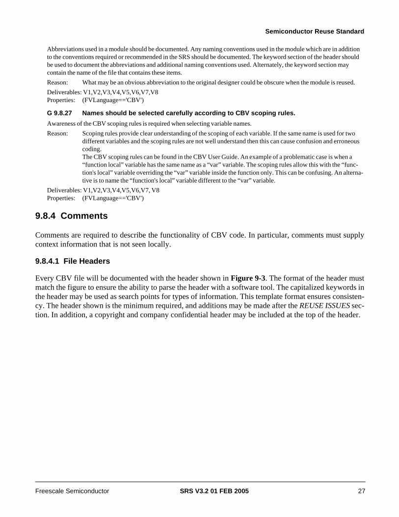
Semiconductor Reuse Standard
Abbreviations used in a module should be documented. Any naming conventions used in the module which are in addition to the conventions required or recommended in the SRS should be documented. The keyword section of the header should be used to document the abbreviations and additional naming conventions used. Alternately, the keyword section may contain the name of the file that contains these items.
Reason: What may be an obvious abbreviation to the original designer could be obscure when the module is reused.
Deliverables: V1,V2,V3,V4,V5,V6,V7,V8Properties: (FVLanguage=='CBV')
G 9.8.27 Names should be selected carefully according to CBV scoping rules.
Awareness of the CBV scoping rules is required when selecting variable names.
Reason: Scoping rules provide clear understanding of the scoping of each variable. If the same name is used for two different variables and the scoping rules are not well understand then this can cause confusion and erroneous coding.The CBV scoping rules can be found in the CBV User Guide. An example of a problematic case is when a “function local” variable has the same name as a “var” variable. The scoping rules allow this with the “func-tion's local” variable overriding the “var” variable inside the function only. This can be confusing. An alterna-tive is to name the “function's local” variable different to the “var” variable.
Deliverables: V1,V2,V3,V4,V5,V6,V7, V8Properties: (FVLanguage=='CBV')
9.8.4 Comments
Comments are required to describe the functionality of CBV code. In particular, comments must supplycontext information that is not seen locally.
9.8.4.1 File Headers
Every CBV file will be documented with the header shown in Figure 9-3. The format of the header mustmatch the figure to ensure the ability to parse the header with a software tool. The capitalized keywords inthe header may be used as search points for types of information. This template format ensures consisten-cy. The header shown is the minimum required, and additions may be made after the REUSE ISSUES sec-tion. In addition, a copyright and company confidential header may be included at the top of the header.
SRS V3.2 01 FEB 2005 27Freescale Semiconductor
Semiconductor Reuse Standard
Figure 9-3 CBV File Header
R 9.8.28 Each file must contain a file header
Every file must contain a header as shown in Figure 9-3. All fields must be included, even if the data is N/A.
Reason: Provides a standard means of supplying pertinent design information.
Deliverables: V1,V2,V3,V4,V5,V6,V7,V8Properties: (FVLanguage=='CBV')&&(NewIP=='True')
R 9.8.29 Use file header boundary tags (+FHDR & -FHDR)
The +FHDR/-FHDR tags must be used to define the boundary of the header information.
Reason: Easy way to identify the header. Indicates that the header is a file header.
Deliverables: V1,V2,V3,V4,V5,V6,V7,V8Properties: (FVLanguage=='CBV')&&(NewIP=='True')
R 9.8.30 Include file name
The header must include the name of the file.
Reason: Provides an easy way to determine what a file contains.
Deliverables: V1,V2,V3,V4,V5,V6,V7,V8Properties: (FVLanguage=='CBV')&&(NewIP=='True')
// +FHDR------------------------------------------------------------------------// Optional Copyright (c) // Optional Company Confidential // -----------------------------------------------------------------------------// FILE NAME :// DEPARTMENT :// AUTHOR :// AUTHOR’S EMAIL :// -----------------------------------------------------------------------------// RELEASE HISTORY// VERSION DATE AUTHOR DESCRIPTION// 1.0 YYYY-MM-DD name // -----------------------------------------------------------------------------// KEYWORDS : General file searching keywords, leave blank if none.// -----------------------------------------------------------------------------// PURPOSE : Short description of functionality// -----------------------------------------------------------------------------// PARAMETERS// PARAM NAME RANGE : DESCRIPTION : DEFAULT : UNITS// e.g.DATA_WIDTH [32,16] : width of the data : 32 :// -----------------------------------------------------------------------------// REUSE ISSUES// Reset Strategy :// Clock Domains :// Flows :// State machines :// Safety level :// Coverage level:// Constraints :// Other :// -FHDR------------------------------------------------------------------------
SRS V3.2 01 FEB 200528 Freescale Semiconductor

Semiconductor Reuse Standard
R 9.8.31 Include point of contact information
The file header must include the originating department, including group, division, and physical location, author, and author’s email address.
Reason: Required for inquiries beyond the scope of the documentation for the design.
Deliverables: V1,V2,V3,V4,V5,V6,V7,V8Properties: (FVLanguage=='CBV')&&(NewIP=='True')
R 9.8.32 Include a release history
The header must include a release history only for the VC changes checked into the VC Repository, with the most recent release listed last. The date format YYYY-MM-DD must be used. This information is useful to the integrator. A local release history should not be included in the header.
Reason: Required to track the revision history of the design.
Deliverables: V1,V2,V3,V4,V5,V6,V7,V8Properties: (FVLanguage=='CBV')&&(NewIP=='True')
R 9.8.33 Include a keyword section
The header must contain a section of the searching keywords. This string may contain a brief synopsis of the construct’s functionality, or list systems and buses with which the construct was designed to work. Abbreviations and additional naming conventions may also be listed.
Reason: Keywords provide a quick searching mechanism and aid the VC integrator in the appropriate selection of VC blocks. If there are no keywords, the entry should be left blank.
Example: address decoder, coldfire, sbus
Deliverables: V1,V2,V3,V4,V5,V6,V7,V8Properties: (FVLanguage=='CBV')&&(NewIP=='True')
R 9.8.34 Include a purpose section
The header must contain a purpose section describing the construct’s functionality. The purpose must describe what the construct provides and not how.
Reason: Aids understanding of construct functionality.
Deliverables: V1,V2,V3,V4,V5,V6,V7,V8Properties: (FVLanguage=='CBV')&&(NewIP=='True')
R 9.8.35 Include a parameter description
Headers must contain information describing the parameters being used in the construct. The default value must be listed. The valid parameter values must also be indicated in the range field.
Reason: Aids understanding of CBV code.
Deliverables: V1,V2,V3,V4,V5,V6,V7,V8Properties: (FVLanguage=='CBV')&&(NewIP=='True')
9.8.4.2 Additional Construct Headers
Each additional construct (function, task, user-defined primitive) within files will also be documented with the following header. Figure 9-4 contains the header for CBV functions, user-defined primitives, and tasks. The format of the header must match the figure to ensure the ability to parse the header with a software tool. The capitalized keywords in the headers may be used as search points for types of information. This template format assures consistency.
SRS V3.2 01 FEB 2005 29Freescale Semiconductor

Semiconductor Reuse Standard
Figure 9-4 CBV Functions, User-Defined Primitives and Tasks Header
R 9.8.36 Additional constructs in file use a header
All of the additional constructs used in a file must be documented with a header as illustrated (see Figure 9-4). All fields must be included, even if the data is N/A.
Reason: Provides a standard means of supplying pertinent design information.
Deliverables: V1,V2,V3,V4,V5,V6,V7,V8Properties: (FVLanguage=='CBV')&&(NewIP=='True')
R 9.8.37 Use construct header boundary tags (+HDR & -HDR)
The +HDR/-HDR tags must be used to define the boundary of the header information.
Reason: Easy way to identify the header. Indicates that the header is a construct header.
Deliverables: V1,V2,V3,V4,V5,V6,V7,V8Properties: (FVLanguage=='CBV')&&(NewIP=='True')
R 9.8.38 Include construct name
Construct headers must include the name of the additional construct.
Reason: Provides an easy way to determine what a construct contains.
Deliverables: V1,V2,V3,V4,V5,V6,V7,V8Properties: (FVLanguage=='CBV')&&(NewIP=='True')
R 9.8.39 Include construct type
Construct headers must include the construct type.
Reason: Provides an easy way to determine what a construct contains.
Deliverables: V1,V2,V3,V4,V5,V6,V7,V8Properties: (FVLanguage=='CBV')&&(NewIP=='True')
R 9.8.40 Include a purpose section
Construct headers must contain a purpose section describing the construct functionality. The purpose must describe what the unit provides and not how.
Reason: Aids understanding of construct functionality.
Deliverables: V1,V2,V3,V4,V5,V6,V7,V8Properties: (FVLanguage=='CBV')&&(NewIP=='True')
// +HDR ------------------------------------------------------------------------// NAME : // TYPE : TYPE can be func, task, primitive// -----------------------------------------------------------------------------// PURPOSE : Short description of functionality// -----------------------------------------------------------------------------// PARAMETERS// PARAM NAME RANGE : DESCRIPTION : DEFAULT : UNITS// e.g. DATA_WIDTH_PP [32,16] : width of the data : 32 :// -----------------------------------------------------------------------------// Other : Leave blank if none.// -HDR ------------------------------------------------------------------------
SRS V3.2 01 FEB 200530 Freescale Semiconductor

Semiconductor Reuse Standard
R 9.8.41 Include a parameter description
Construct headers must contain information describing the parameters being used in the construct. The default value must be listed.
Reason: Aids understanding of CBV code.
Deliverables: V1,V2,V3,V4Properties: (FVLanguage=='CBV')&&(NewIP=='True')
R 9.8.42 Other header documentation
The construct header should include additional pertinent information which is useful to the integrator or makes the code more understandable.
Reason: Aids in understanding the design
Deliverables: V1,V2,V3,V4,V5,V6,V7,V8Properties: (FVLanguage=='CBV')
9.8.4.3 Other Comments
Comments are required to describe the functionality and flow of CBV code. They must be sufficient foranother designer to understand and maintain the code.
R 9.8.43 Comment functional sections
Each functional section of the code must be preceded by comments describing the code’s intent and function.
Reason: Aids understanding of the code.
Deliverables: V1,V2,V3,V4,V5,V6,V7,V8Properties: (FVLanguage=='CBV')&&(NewIP=='True')
R 9.8.44 Document unusual or non-obvious implementations
Unusual or non-obvious implementations must be explained and their limitations documented with a comment.
Reason: Improves readability of the code. Purpose and implications of unusual or non-obvious implementations will, in general, require an explanation.
Deliverables: V1,V2,V3,V4,V5,V6,V7,V8Properties: (FVLanguage=='CBV')&&(NewIP=='True')
R 9.8.45 Delete old code
Old code, or unused code must be deleted as opposed to commented out.
Reason: Eases understanding.
Deliverables: V1,V2,V3,V4,V5,V6,V7,V8Properties: (FVLanguage=='CBV')&&(NewIP=='True')
R 9.8.46 Comment template instantiations
A comment must be used to explain the functionality of any instantiated template and why the template is instantiated and not inferred.
Deliverables: V1, V2, V3, V4Properties: (FVLanguage=='CBV')&&(NewIP=='True')
G 9.8.47 Comment variable declarations
Every variable declaration, such as vars and assigns, must have a descriptive comment, preferably on the same line. If the comment is not on the same line, it should be on the preceding line.
Reason: Improves readability.
Exception: Auto-generated declarations.
SRS V3.2 01 FEB 2005 31Freescale Semiconductor
Semiconductor Reuse Standard
Deliverables: V1,V2,V3,V4Properties: (FVLanguage=='CBV')
G 9.8.48 Use ‘///’ for line coverage comments
Reason: Differentiates line coverage comments from regular line comments.
Deliverables: V3,V4Properties: (FVLanguage=='CBV')
G 9.8.49 Comment end and endcase statements
It is recommended that every end and endcase statement have a comment specifying what construct it ends.
Reason: Improves readability. Easier to identify the bounds of a construct.
Exception: A “begin … end” or “case … endcase” pair containing five or less lines of code may omit the end comments.
Example: task foo();
begin ... end // task foo();
Deliverables: V1,V2,V3,V4Properties: (FVLanguage=='CBV')
G 9.8.50 Use comments liberally
It is recommended that comments be used liberally throughout the code to describe the code intent, functionality, design process, and special handling. Avoid obvious comments. (e.g., a <= b; /* save b into a */)
Reason: Improves understanding of the code.
Deliverables: V1,V2,V3,V4, V5, V6, V7, V8Properties: (FVLanguage=='CBV')
9.8.5 Code Style
R 9.8.51 Write code in a tabular format
Code must be written in a tabular manner (i.e., code items of the same kind are aligned).
Reason: Improves readability. When writing a code block (begin, case, if statements, etc.), it is useful to complete the frame first, in particular to align the end of the code block with the begin.
Deliverables: V1,V2,V3,V4,V5,V6,V7,V8Properties: (FVLanguage=='CBV')&&(NewIP=='True')
G 9.8.52 Use consistent code indentation with spaces
Consistent indentation should be used for code alignment. Spaces should be used instead of tab stops.
Reason: Improves readability. Tab stops should not be used because they may be interpreted differently in different systems.
Note: Excessive indentation may actually hinder readability.
Deliverables: V1,V2,V3,V4,V5,V6,V7,V8Properties: (FVLanguage=='CBV')&&(NewIP=='True')
R 9.8.53 One CBV statement per line
One line must not contain more than one statement. Do not concatenate multiple semicolon separated CBV statements on the same line.
Reason: Improves readability. Easier to parse code with a design tool.
SRS V3.2 01 FEB 200532 Freescale Semiconductor

Semiconductor Reuse Standard
Example: Use:
upper_en = (p5type && xadr1[0]); lower_en = (p5type && !xadr1[0]);
Do not use:
upper_en = (p5type && xadr1[0]); lower_en = (p5type && !xadr1[0]);
Exception: Comments are allowed on the same line as a CBV statement.
Deliverables: V1,V2,V3,V4,V5,V6,V7,V8Properties: (FVLanguage=='CBV')&&(NewIP=='True')
G 9.8.54 Line length not to exceed 80 characters
It is recommended that line length not exceed 80 characters.
Reason: Improves readability, and avoids inadvertent line wraps.
Deliverables: V1,V2,V3,V4,V5,V6,V7,V8Properties: (FVLanguage=='CBV')
9.8.6 Module Partitioning and Reusability
R 9.8.55 Use templates to allow binding to any Verilog instance
The CBV template construct should be used to wrap a CBV module declaration. This allows binding to any appropriate Verilog instance.
Reason: Improves reusability.
Example: template generic_module parameters() ports() strings(instance_path)module ‘instance_path’;...endmoduleendtemplate
generic module::instance a1 parameters() ports() strings(“top.module1”);generic module::instance a2 parameters() ports() strings(“top.module2”);
Deliverables: V1,V2,V3,V4Properties: (FVLanguage=='CBV')&&(NewIP=='True')
R 9.8.56 Use templates for writing generic tasks and functions.
Variables referenced from within tasks can be template ports. This will allow writing tasks and functions in a generic fashion.
Reason: Improves reusability.
Example:
Deliverables: V1,V2,V3,V4Properties: (FVLanguage=='CBV')&&(NewIP=='True')
R 9.8.57 Use templates ports for passing DUT signal names to the CBV code.
Reason: Improves reusability by making CBV code independent from the hierarchical structure of design.
Example:
Deliverables: V1,V2,V3,V4Properties: (FVLanguage=='CBV')&&(NewIP=='True')
SRS V3.2 01 FEB 2005 33Freescale Semiconductor

Semiconductor Reuse Standard
R 9.8.58 Bus sizes of standard protocols should be template parameters
Use the parameter area to pass bus sizes within templates. This will provide writing code that can suite all possible bus sizes.
Reason: Improves reusability and allows parameterizable verification IP.
Deliverables: L1,V1,V2,V3,V4Properties: (FVLanguage=='CBV')&&(NewIP=='True')
R 9.8.59 Use tasks that are parameterized for common functionality sequences
CBV tasks add modularity when describing sequences. Sequences may have similar flows differentiated by parameters.
Reason: Improves reusability and allows parameterizable verification IP.
Deliverables: V3,V4Properties: (FVLanguage=='CBV')&&(NewIP=='True')
R 9.8.60 Use a recursive task for repetitive sequences.
A repetitive sequence for example are handling of data beats in a burst request. The task is called recursively to handle each data beat.
Reason: Requires less code.
Deliverables: V3,V4Properties: (FVLanguage=='CBV')&&(NewIP=='True')
R 9.8.61 Use functions that are parameterized for common combinational logic
CBV functions add modularity when describing combinational logic.
Reason: Improves reusability and allows parameterizable verification IP.
Deliverables: V1, V2, V3,V4, V5, V6, V7Properties: (FVLanguage=='CBV')&&(NewIP=='True')
R 9.8.62 Combine multiple CBV files using a single file which uses the ‘include construct to include the CBV files
Reason: This is the only way for working at the integration level.
Deliverables: V1, V2, V3,V4Properties: (FVLanguage=='CBV')&&(NewIP=='True')
R 9.8.63 Do not add path information when using the ‘include construct
When using the ‘include construct the location of files should be detected by passing directories through the different tool parameters. See +incdir+<dir1>+ ... in the cbv_sim command.
Reason: This makes the codes location independent from the source files. The location is determined at the tool level and not by the source code.
Deliverables: V1, V2, V3,V4Properties: (FVLanguage=='CBV')&&(NewIP=='True')
R 9.8.64 Create a file named cbv_init.cbv which will define ‘ifdef guards for all other CBV files
The cbv_init.cbv file should contain ‘define’s which determine what is being executed within the rest of the CBV files. What is being executed is determined by using the ‘ifdef construct.
Reason: What is being executed in determined in one place.
Deliverables: V1, V2, V3,V4Properties: (FVLanguage=='CBV')&&(NewIP=='True')
G 9.8.65 Avoid using internal design signals
Reason: Internal design signals may change or disappear during Syntheses. Referring to internal design signal increases the dependency of CBV code on design changes.
SRS V3.2 01 FEB 200534 Freescale Semiconductor

Semiconductor Reuse Standard
Deliverables: V1,V2,V3,V4,V5,V6,V7Properties: (FVLanguage=='CBV')
9.8.7 CBV Good Practices
R 9.8.66 Do not use the “if +(0 to *)” construct as a root statement within the main begin/end block
Reason: Using this could cause a thread overflow because on each cycle a new thread is being created from the main begin/end and that thread continues to live while the if condition is true.
Deliverables: V3,V4Properties: (FVLanguage=='CBV')&&(NewIP=='True')
R 9.8.67 Use high level data types when possible.
Reason: Simplifies writing code with array, struct like data structures.
Deliverables: V1, V2, V3,V4Properties: (FVLanguage=='CBV')&&(NewIP=='True')
R 9.8.68 Use CBV_INIT for initializing var variables
Reason: Var variables should be assigned an initial state at the beginning of simulation. CBV_INIT is a CBV key word that is true at the start of execution and false otherwise. This variable can be used to detect when to initialize a var variable.
Deliverables: V1, V2, V3,V4Properties: (FVLanguage=='CBV')&&(NewIP=='True')
9.8.8 General Coding Techniques
R 9.8.69 Expression in condition must be a 1-bit value
The conditions in the following constructs must be an expression that results in a 1-bit value:
1. if(condition)
2. while(condition)
3. for(initial_assignment; condition; step_assignment)
4. @(posedge condition or ...)
5. @(negedge condition or ...)
6. variable = (condition)? exp1 : exp2
Reason: Avoid nonstandard simulator behavior.
Example: // A signal called bus_is_active is set to 1 whenever bus, a multi-bit value, // has a value other than 0.
if (bus) bus_is_active == 1; // bus is a multi-bit value, // which violates the rule
if (bus > 0) bus_is_active == 1;// the resulting control condition is a 1-bit// expression, as suggested by the rule,// which is intuitively easier to read
Deliverables: V1,V2,V3,V4Properties: (FVLanguage=='CBV')&&(NewIP=='True')
R 9.8.70 Use consistent ordering of bus bits
When describing multi-bit buses, a consistent ordering of the bits must be maintained.
Reason: Eases readability and reduces inadvertent order swapping between buses.
SRS V3.2 01 FEB 2005 35Freescale Semiconductor
Semiconductor Reuse Standard
Exception: VC blocks which internally use one convention, but interface to the other convention at the VC block boundary.
Deliverables: V1,V2,V3,V4,V5,V6,V7Properties: (FVLanguage=='CBV')
R 9.8.71 Do not assign signals to x
The value of x must not be assigned to variables. Known legal signal values must be assigned to all signals.
Reason: Avoids x propagation through the logic.
Deliverables: V1, V2, V3, V4Properties: (FVLanguage=='CBV')
G 9.8.72 Use parameters instead of text macros for symbolic constants
It is recommended that template parameters be used instead of text macros (‘define) to specify symbolic constants.
Reason: The scope of ‘define text macros is global unless they are explicitly undefined. This may cause compilation order dependencies and conflicts at the SoC level. Also, parameter values may be customized for each instance of a module.
Exception: Global constants.
Deliverables: V1,V2,V3,V4Properties: (FVLanguage=='CBV')
R 9.8.73 Text macros must not be redefined
Text macros must not be redefined to a different value. This applies to locally and globally-defined macros.
Reason: Avoids inadvertent redefinition of macros.
Deliverables: V1,V2,V3,V4, V5, V6, V7, V8Properties: (FVLanguage=='CBV')
G 9.8.74 Preserve relationships between constants
If a constant is dependent on the value of another constant, the dependency should be shown in the definition. Where a text macro defines an arithmetic or logical expression, it should be enclosed in parentheses.
Reason: Increased adaptability, as code changes required for adaptation are reduced.
Example: Preferred:
‘define DATA_WORD 8 ‘define DATA_LONG (4 * ‘DATA_WORD)
instead of:
‘define DATA_WORD 8 ‘define DATA_LONG 32
Deliverables: V1,V2,V3,V4Properties: (FVLanguage=='CBV')
R 9.8.75 Use text macros for base addresses
If the base address of a module appears in the CBV code, it must be assigned with a text macro.
Reason: Eases changing the memory map of a module.
Exception: The base address is defined in software.
Deliverables: V1,V2,V3,V4,V5,V6,V7Properties: (FVLanguage=='CBV')&&(NewIP=='True')
SRS V3.2 01 FEB 200536 Freescale Semiconductor

Semiconductor Reuse Standard
R 9.8.76 Use base + offset for address generation
All accesses to a register/memory location within a module must be formed by using a base address and the offset from the base.
Reason: Eases retargeting to different system configurations.
Deliverables: V1,V2,V3,V4,V5,V6,V7Properties: (FVLanguage=='CBV')&&(NewIP=='True')
G 9.8.77 Use text macros for register field positions and values
Text values should be used for register field positions and field values rather than numerical constants. The fields may be one or more bits or the entire register.
Reason: Improves readability and maintainability. Reduces the chance of using the wrong bits or the wrong value.
Example: ‘define CNT_WHAT cnt_ctrl[7:5] // What to count‘define CNT_ADDR 2’b00 // count address matchesif (cnt_in) begin counter <= 1’b1; if (‘CNT_WHAT = CNT_ADDR) addr_flag == 1;
end
Deliverables: V1,V2,V3,V4Properties: (FVLanguage=='CBV')
G 9.8.78 Use text macros for signal hierarchy paths
Commonly used signal hierarchy paths should be specified using a text macro. Hierarchical signal paths are not allowed in code that is intended to be synthesized.
Reason: Simplifies remapping to a new environment.
Example: ‘define XXX_TESTBENCH si ‘define XXX_TOP_SCOPE ‘TESTBENCH.xxx // xxx is the top-level module ‘define XXX_YYY_SCOPE ‘XXX_TOP_SCOPE.yyy // yyy is a submodule of xxx
Deliverables: V1,V2,V3,V4,V5,V6Properties: (FVLanguage=='CBV')
R 9.8.79 Limit ‘ifdef nesting to three levels
Nesting of ‘ifdef directives must not exceed three levels.
Reason: Eases understanding of the code.
Deliverables: V1,V2,V3,V4,V5,V6,V7Properties: (FVLanguage=='CBV')&&(NewIP=='True')
R 9.8.80 Operand sizes must match
No expression may have its size implicitly extended or reduced.
Reason: With different operand sizes, the operand is not explicitly defined, but depends on how CBV resolves the size differences. CBV allows this since it is not a highly typed language.
Example: The following should all be avoided: wire [63:0] wire64bit; wire [ 7:0] wire8bit;
assign wire8bit [ 7:0] = 1; // assigns integer (32-bit) to 8-bit net assign wire64bit[63:0] = 1; // assigns integer (32-bit) to 64-bit net assign wire64bit[63:0] = ‘b1; // assigns unsized number to 64-bit net
SRS V3.2 01 FEB 2005 37Freescale Semiconductor

Semiconductor Reuse Standard
assign wire64bit[63:0] = wire8bit; // assigns 8-bit expression to 64-bit net assign wire64bit[63:0] = wire64bit & wire8bit; // bit-wise AND of 8-bit and 64-bit nets
Deliverables: V1,V2,V3,V4,V5,V6,V7Properties: (FVLanguage=='CBV')
G 9.8.81 Use parentheses in complex equations
Parentheses should be used to force the order of operations.
Reason: Large equations without parentheses depend on the order preference of the language to determine the func-tionality of the equations. Parentheses explicitly order the operations of the equations, and clearly convey the functionality.
Deliverables: V1,V2,V3,V4,V5,V6,V7Properties: (FVLanguage=='CBV')
G 9.8.82 Use functional statements when writing complex combinational logic
Reason: Regular functions require recursive functions to achieve looping logic that is complex to debug and maintain. Functional statements have “for” and “while” loops. Functional statements also allow assignment to temporary variables.
Deliverables: V1,V2,V3,V4,V5,V6,V7Properties: (FVLanguage=='CBV')
9.9 Verilog Specific Coding Standards
This section contains the rules and guidelines for verification specific coding. The rules are a superset ofthe coding standards. This section will eventually be integrated into the coding standard. There has beena special effort to make as many of the standards as language and tool independent as possible. Standardcoding guidelines aid VC creators and integrators to share design data and develop SoC solutions.
R 9.9.1 Synthesizable and behavioral code must be partitioned in separate files
Behavioral code in this case is referring to code that is not synthesizable. If the language is verilog, the synthesizable and behavioral code would be in separate locations.
Reason: Eases mapping to emulation and hardware accelerators.
Deliverables: V1,V2,V3,V4,V5,V6Properties: (NewIP==’True’)
R 9.9.2 Unless variables are used globally, local declarations must be in named code blocks
A named code block in this case is code bounded by a begin-end sequence with a label on the begin. Variables is this case are integers, wires, and regs.
Reason: Avoids accidental interferences with other verification code which may produce unexpected results.
Example: always @(posedge ipg_clk)
Example: being: my_block_test
Example: int aa;
Example: aa = aa + 1;
Example: end
Deliverables: V1, V2,V3,V4,V5,V6Properties: (FVLanguage=='Verilog')&&(NewIP=='True')
SRS V3.2 01 FEB 200538 Freescale Semiconductor

Semiconductor Reuse Standard
9.9.1 Symbolic Constants
This section contains rules and guidelines for symbolic constants. In Verilog, symbolic constants are textmacros and parameters. In Verilog, both defines and parameters have advantages and disadvantages. Usersshould choose what is appropriate for their needs. For example, parameters allow different values to beassigned to different instances. Defines allow setting values for multiple code modules (i.e., VC) from asingle location.Where both parameters and defines do the job equally well, parameters are preferable because they elim-inate the problem of a conflict with using the same name defined somewhere else.
R 9.9.3 The default parameter settings must specify a verified implementation
Reason: Ensure testbench operates in the default configuration.
Deliverables: V1Properties: (NewIP=='True')
R 9.9.4 Parameters must be setable from the simulator command line
This allows configurations to be managed external to the testbench. For verilog, this could be accomplished by setting parameter constructs to ‘define variables. The ‘defines can be set from the simulator command line. This enables the testbench to be compiled into different configurations without editing design or verification code. For verilog, the defines could also be placed in a separate file and passed in.
Reason: VC does not have to be modified to run a new configuration.
Example: `define IPI_BUS_WIDTH=32
Deliverables: V1
G 9.9.5 It is recommended that address offsets be specified by defines
The offset to a base address should be specified with a define.
Reason: Changes in register maps are easier to handle. It also makes the code more readable.
Deliverables: V1, V2,V4
G 9.9.6 It is recommended that register offset names end with “_OFFSET”
Text macro names should be named as <VC_prefix>_<reg_name>_OFFSET.
Reason: This allows for consistency and ease of relocating devices and registers in memory.
Deliverables: V1, V2,V4Properties: (NewIP=='True')
G 9.9.7 It is recommended that the base address names end with “_BASE”
Reason: This allows for consistency and ease of relocating devices in memory.
Example: <VC_name>_BASE = 100
Deliverables: V1, V2,V4Properties: (NewIP=='True')
G 9.9.8 It is recommended that defines be used for frequently used values
If a value is used frequently in a specific stand-alone device stimulus, use a define statement.
Reason: Defines improve readability and simplify the porting of a stimulus to different environments and chips.
Deliverables: V1, V2,V3,V4,V5,V7Properties: (NewIP=='True')
SRS V3.2 01 FEB 2005 39Freescale Semiconductor

Semiconductor Reuse Standard
9.9.2 Routines
Efficient verification relies on using routines, macros, functions, and so on to raise coding to a higher levelof abstraction. This technique helps to avoid coding errors caused by cut and paste of common code blocks.It is useful to standardize the format of routine names to ease identification and classification of routinecalls, and to ensure uniqueness in an SoC environment.
R 9.9.9 All VC-specific routine names must be lower case
Routines that are only used by one VC must be in lower case.
Reason: Improves readability and makes it easy to determine if a routine call is VC specific (local).
Deliverables: V1, V2,V3,V4,V5,V7Properties: ((FVLanguage=='Verilog')||(FVLanguage=='VHDL'))&&(NewIP=='True')
R 9.9.10 All VC-specific routines must be preceded at least two unique characters
Failure to precede new routines with the unique characters could produce warning or error messages and the incorrect redefinition of a routine. VC-specific routines imply routines which are not part of the common command set.
Reason: Many VC share similar routine names. Using a generic routine name may cause non-execution of the simula-tion.
Example: <VC_name>_try_routines instead of try_routines
Deliverables: V1, V2,V3,V4,V5,V7Properties: ((FVLanguage=='Verilog')||(FVLanguage=='VHDL'))&&(NewIP=='True')
G 9.9.11 It is recommended that the disabling of routines occurs internally
Routines should not be disabled from other parts of the verification code if they can be disabled internally. If disabling code is required, a named begin/end sequence should be disabled from within the task.
Reason: Avoids unspecified simulator behavior.
Example: task writebegin: write_access if (abort) begin disable write_access; end ...end
Deliverables: V1Properties: (NewIP=='True')
G 9.9.12 It is recommended that routines be disabled from a single location
If routines can not be disabled internally, it is recommended to have all the disable constructs originate from the same block of code.
Reason: Reduces maintenance to a single location.
Deliverables: V1, V7Properties: (NewIP=='True')
9.9.3 Signal Access
Care must be taken when using internal signals for verification to ensure that problems will not arise duringthe various stages of verification.
SRS V3.2 01 FEB 200540 Freescale Semiconductor

Semiconductor Reuse Standard
R 9.9.13 Reference to internal signals must be via text macros
Reference to internal signals is strongly discouraged, but is not prohibited. For the rare situations in which it is justified, it must at least be done by a consistent method.
Reason: Internal signals may not survive synthesis. They may be removed entirely, or exist by a different name. This rule provides for name change of signals referenced by the stimulus.
Deliverables: V7
R 9.9.14 Internal signals referenced must be listed in a single location
Reference to internal signals is strongly discouraged, but is not prohibited. For the rare situations in which it is justified, it must at least be done by a consistent method.
Reason: Ease of locating.
Deliverables: V7Properties: (NewIP=='True')
R 9.9.15 Internal signals referenced must be preserved through synthesis
Appropriate synthesis constraints must be applied to guarantee that signals referenced by tests will not be deleted during synthesis.
Reason: Internal signals may not survive synthesis. They may be removed entirely, or exist by a different name. This rule prevents signals referenced by tests from being deleted.
Deliverables: V7Properties: (NewIP=='True')
G 9.9.16 It is recommended that signals be referenced at the VC boundary
Signals referenced by simulation should cross a VC boundary. The boundary may not be flattened during synthesis (preserved).
Reason: This is a secure way to preserve the signal names between RTL and gate level netlist.
Deliverables: V1,V2
G 9.9.17 It is recommended that internal signals should not be forced
It is recommended to only drive signals on the VC boundary to verify the VC. If the VC is more complex, signals may be brought through an additional test bus to observe interesting (required) internal points (state vectors, etc.). The test bus crosses the VC boundary. It is also possible to observe this test bus in a special test mode on a full chip simulation on the pads. Due to this fact it is possible to use this bus for silicon debugging.
High-level models must match low-level models in terms of flexibility and what will exist on the silicon. Internal signals are not visible on the tester, therefore any forces will have no meaning or effect.
Reason: It slows down simulation and may inhibit incremental compilation. In addition to that, internal forces can not be implemented on a tester. So the device must operate in simulation without any internal forces and uses special test modes instead of the forces.
Exception: Forcing signals to test isolation of power supply modes.
Internal signals must be forced to logic 0 and logic 1 if it is necessary to verify a portion of the specification.
Deliverables: V1, V2, V7
9.10 Vera Specific Coding Standards
The following paragraphs describe the coding requirements for Vera. Each rule and guideline is prefixwith [<source file> - <page #>] that indicate the source of the requirement. Table 9-1 contains the acro-nyms used for the source references.
SRS V3.2 01 FEB 2005 41Freescale Semiconductor

Semiconductor Reuse Standard
9.10.1 Coding
9.10.1.1 Lexical Rules
R 9.10.1 Do not use System Verilog keywords for Vera identifiers
Reason: Vera code is not portable to System Verilog. Choose other identifiers instead.
Deliverables: V1, V2, V3, V4, V7, V14, V15Properties: (FVLanguage==‘Vera’)
9.10.1.2 Style
R 9.10.2 [CS - page 11, VW p4-6] Use only // for comments, do not use /* */
Reason: Consistency, parsing and searching clarity. For example, grep can return comments which look like code from a multi-line comment body if // is not used.
Example:
Deliverables: V1, V2, V3, V4, V7, V14, V15Properties: (FVLanguage==‘Vera’)
Table 9-1 Rule Source References
Ref DocumentA The Art of Verification
VR “Synopsys Vera Review” Document dated 2/13/2003
VC “Synopsys Vera Compilation” Document dated 2/13/2003
KD Ken Davis Notes from March 11, 2003 Vera Training Course
VW Introduction to Vera Workshop Student Guide 2000 (37491-000-S12)
CV Coding In Vera: Guidelines and Performance Suggestions
CS Vera Coding Style Guide 10/31/2001
TB-CvE TBARD Cycle Verse Event Based Slides
// Task: publish// Inputs: monitor event, comment, message severity// Outputs: none.// Description: example of good coding styletask SPSIndentBase::publish(SPSEventBase evt, string comment, MH_MESSAGE_SEVERITY severity=SEV_INFO){ // Indent by two spaces if (pend_cnt == 1) { // Indent by two more spaces if (current_array[ii] == evt) { // Indent by two more spaces event_location=ii; } }}
SRS V3.2 01 FEB 200542 Freescale Semiconductor
Semiconductor Reuse Standard
R 9.10.3 [CS - page 11] Delete unused code
Reason: Revision control systems are meant to handle old code. Old code commented out confuses and scare integra-tors for good reason.
Deliverables: V1, V2, V3, V4, V7, V14, V15Properties: (FVLanguage==‘Vera’)
G 9.10.4 [CS - page 12] A line must contain only one statement
Reason: Readability. Maintainability.
Deliverables: V1, V2, V3, V4, V7, V14, V15Properties: (FVLanguage==‘Vera’)
G 9.10.5 [CV - page4] Opening and closing braces must be indented to the same level and on their own line
Reason: Readability
Example: See example for R 9.10.2.
Example: randseq definitions may surround function calls with {} on a single line for readability.
Deliverables: V1, V2, V3, V4, V7, V14, V15Properties: (FVLanguage==‘Vera’)
G 9.10.6 [CV - page4] Use a consistent number of spaces to indent code
Reason: Tabs should be avoided as tab may be different on different systems. Using a common number of spaces to indent make the code more consistent and easier to read.
Example: Consistently Indenting 2 or 4 spaces at a time
Example: See example for R 9.10.2.
Deliverables: V1, V2, V3, V4, V7, V14, V15Properties: (FVLanguage==‘Vera’)
G 9.10.7 [CS - page 11] Comparison operators must have white space before and after the operator
Reason: Readability.
Example: if (XYZ<SPACE>==<SPACE>TRUE), also see example for R 9.10.2.
Deliverables: V1, V2, V3, V4, V7, V14, V15Properties: (FVLanguage==‘Vera’)
G 9.10.8 [CS - page 12] List only one argument per line if the line with all the arguments exceeds 80 characters
Reason: Readability. Maintainability. Arguments that are listed on separate lines should be aligned.
Example: See example for R 9.10.2.
Deliverables: V1, V2, V3, V4, V7, V14, V15Properties: (FVLanguage==‘Vera’)
G 9.10.9 [CS - page 12] Lines should not exceed 80 characters
Reason: Readability. Maintainability.
Deliverables: V1, V2, V3, V4, V7, V14, V15Properties: (FVLanguage==‘Vera’)
SRS V3.2 01 FEB 2005 43Freescale Semiconductor

Semiconductor Reuse Standard
9.10.1.3 Language Constructs
R 9.10.10 [TB-CvE] Do not use the “delay” task
Vera supports the use of a “delay” task that causes Vera code execution to stop and return control to the simulator for a specified number of inter-cycle ticks. Use loops, mailboxes, semaphores, regions, events, or any other method that is guaranteed to run the same regardless of clock or evaluation frequency.
Reason: Compatibility with other code, performance degradation caused by additional simulator evaluations within a cycle or the timestep may change.
Example: delay(5); // delay Vera code for 5 HDL simulator timesteps. DO NOT USE.
Deliverables: V1, V2, V3, V4, V7, V14, V15Properties: (FVLanguage==‘Vera’)
R 9.10.11 [A - 134]Always use soft expects rather than hard expects
Reason: Soft expects do not generate simulation errors when they are not satisfied. Instead the set an error flag and allows the simulation to continue. You can check if an error flag has been set using the flag() system function
Example: @1,4 bus.data != 4’bxxxx soft;
Deliverables: V1, V2, V3, V4, V7, V14, V15Properties: (FVLanguage==‘Vera’)
R 9.10.12 [A - 449] Do not rely on thread ordering
Reason: Compilation changes may cause thread execution order changes.
Deliverables: V1, V2, V3, V4, V7, V14, V15Properties: (FVLanguage==‘Vera’)
R 9.10.13 [A - 182] Do not use “suspend_thread”
Reason: Vera has many built in synchronization constructs. Suspend_thread can easily cause race conditions.
Exception: This rule does not apply to the SPS base class which uses this construct for event publishing. Since the base class uses this construct it is not safe for other code to use this construct as they may “out wait” the event publishing mechanism the base class which could cause undesired testbench behavior.
Deliverables: V1, V2, V3, V4, V7, V14, V15Properties: (FVLanguage==‘Vera’)
R 9.10.14 [VR - slide 46] Only use integers for looping constructs
Reason: Performance, bit type allows for X and Z values creating more simulator overhead.
Deliverables: V1, V2, V3, V4, V7, V14, V15Properties: (FVLanguage==‘Vera’)
R 9.10.15 [KD] Do not use global variables
Reason: Forces the SOC integrator to have to manage name space collisions. Makes code fragile, difficult to understand and debug and reuse. If a variable needs to be shared between two classes, function calls can be used to pass variables.
Deliverables: V1, V2, V3, V4, V7, V14, V15Properties: (FVLanguage==‘Vera’)
R 9.10.16 [CV - page18] All waveform data storage must be turned off by default
Reason: Performance issue for integrator.
Deliverables: V1, V2, V3, V4, V7, V14, V15Properties: (FVLanguage==‘Vera’)
SRS V3.2 01 FEB 200544 Freescale Semiconductor

Semiconductor Reuse Standard
R 9.10.17 [A - 154] Always set the id parameter to zero when allocating regions, mailboxes, and sema-phores
Reason: There’s no need to track them. Let Vera take care of it.
Deliverables: V1, V2, V3, V4, V7, V14, V15Properties: (FVLanguage==‘Vera’)
G 9.10.18 [KD] Always set the count equal to one on region, semaphore, and mailbox memory alloca-tions
Reason: Allocating multiple regions, semaphores, or mailboxes forces the user to add constant offsets to the returned ID. This makes the code less readable. Using separate variables for each ID forces multiple calls to alloc() but makes code easier to read and saves from having to track IDs. This requirement also reduces the exposure to run time data type mismatches when different types of data are stored in the mailboxes, regions, or semaphores returned by the allocation request.
Example:
Deliverables: V1, V2, V3, V4, V7, V14, V15Properties: (FVLanguage==‘Vera’)
R 9.10.19 Only allocate mailboxes, semaphores, and regions at the class level
Note: “at the class level” means during construction. Theses items must not be allocated in subroutines.
Reason: They are a limited resource and Vera may run out of mailboxes or memory since they can not be de-allocated.
// Allocate three unique regionsregion_a = alloc(REGION,0,1);region_b = alloc(REGION,0,1);region_c = alloc(REGION,0,1);
// Create the mailboxesdata_mailbox_id = alloc(MAILBOX,0,1)addr_mailbox_id = alloc(MAILBOX,0,1)
// Put data in the mailboxmailbox_put(data_mailbox_id, data);mailbox_put(addr_mailbox_id,addr);
SRS V3.2 01 FEB 2005 45Freescale Semiconductor

Semiconductor Reuse Standard
Example:
Deliverables: V1, V2, V3, V4, V7, V14, V15Properties: (FVLanguage==‘Vera’)
G 9.10.20 [VR - slide 46] Value change alerts (VCA) should be avoided
Reason: If a signal changes frequently it should be sampled and tested in monitor code because the run time perfor-mance will be much better for a signal that changes frequently due to the performance penalty of a VCA trig-gering. If a signal changes infrequently, the testbench performance will be improved by using the VCA because the overhead of the VCA will be much lower than having the signal sampled and evaluated frequently.
Example:
Deliverables: V1, V2, V3, V4, V7, V14, V15Properties: (FVLanguage==‘Vera’)
G 9.10.21 [VR - slide 46] Do not use arithmetic operators on vectors larger than 32 bits
Reason: Arithmetic on large vectors should be performed on integers, not bit vectors for faster performance. Bit vectors are 4 state variables which require more computation to manipulate.
Deliverables: V1, V2, V3, V4, V7, V14, V15Properties: (FVLanguage==‘Vera’)
G 9.10.22 [VW - page 7-25] Do not use “wait_var()”
virtual class Xyz extends ABCBase{ // local local integer cmd_sem;
// public
// constructor // if your driver can process multiple commands concurrently // pipelined bus), you should set the sem_keys field to // the maximum number of allowable concurrent commands. task new(string name, integer sem_keys=1);
... protected task get_semaphore(SPSCommandBase cmd); protected task put_semaphore(SPSCommandBase cmd);}
// Class Method definition
task Xyz::new(string name, integer sem_keys=1){ super.new(name); debug(“New Xyz object constructed”); cmd_sem = alloc(SEMAPHORE, 0, 1, sem_keys);}
//Within an interface specification do not use the value chan(VCA) qualifier input b PSAMPLE vca hdl_node “top.b” input d PSAMPLE vca hdl_node “top.d”
//Define interface as follows input b PSAMPLE hdl_node “top.b” input d PSAMPLE hdl_node “top.d”
SRS V3.2 01 FEB 200546 Freescale Semiconductor

Semiconductor Reuse Standard
Reason: Use of “wait_var” may not be a synchronization method that is compatible with the base class. The value must change or the code remains blocked. Events are preferred since they trigger regardless of whether the value changes. Recommend using the trap and test features of the SPS base class.
Exception: .Use of wait_var() is permitted in Coverage objects when sampling events in coverage groups
Example: Good Example
Example: Bad Example
Deliverables: V1, V2, V3, V4, V7, V14, V15Properties: (FVLanguage==‘Vera’)
G 9.10.23 [KD] If a thread within a fork is surrounded by braces, then all threads within the fork must use them
Reason: If Vera requires a thread within a a fork to be surrounded by braces, then all threads within the fork must be encapsulated within the braces. Makes code more readable and eliminates possible confusion with regard to the number of threads being forked.
Example: See example G 9.10.22
Deliverables: V1, V2, V3, V4, V7, V14, V15Properties: (FVLanguage==‘Vera’)
G 9.10.24 [VW - page 7-21] Pass shadow vars to child threads when the value changes outside the scope
Reason: All function calls will get the last value of a loop instead of the current value unless the variable passed in is a shadow variable.
// THE FOLLOWING IS OK SINCE IT IS INSIDE A COVERAGE OBJECTcoverage_group MyCov() { sample_event = wait_var(port_number); sample port_number { state s0(0:7); state s1(8:15); trans t1(“s0”->”s1”); }}
// DO NOT USE THE FOLLOWINGfork { wait_var(data[2]); printf(“Data[2] has changed to %d\n”, data[2]);}{ for (i=0; i<100; i++) { data[i]=random(); @(posedge CLOCK); }}join any
SRS V3.2 01 FEB 2005 47Freescale Semiconductor

Semiconductor Reuse Standard
Deliverables: V1, V2, V3, V4, V7, V14, V15Properties: (FVLanguage==‘Vera’)
9.10.1.4 Classes
G 9.10.25 [CV - page2] A file should not contain more than one class definition
Reason: Maintainability
Exception: A collection of small but logically related classes may be combined into a single file.
Deliverables: V1, V2, V3, V4, V7, V14, V15Properties: (FVLanguage==‘Vera’)
G 9.10.26 [CS - page 6] Defines, Local, Public, and Protected class members should be in separately labeled sections of the code
Reason: Readability. Maintainability.
Example:
Deliverables: V1, V2, V3, V4, V7, V14, V15Properties: (FVLanguage==‘Vera’)
R 9.10.27 Declare virtual methods at each level of hierarchy
Reason: When using virtual classes make sure to declare the virtual method at each level of hierarchy, even if the virtual method is not required at that particular level. This allows a virtual method to be overridden anywhere in the hierarchy without the concern for “holes”.
Deliverables: V1, V2, V3, V4, V7, V14, V15Properties: (FVLanguage==‘Vera’)
// Declare ii as a shadow variableshadow integer ii;for (ii=0; ii<max_value;ii=ii+1) { fork // some_function receives the cur // value of ii because it is a sh // If ii were not shadowed, some_ // would always receive max_value some_function(ii); join none}
class IPSMon extends SPSPublishingMonitorBase{ // local local IPSMonPort ips_mon_port; local bit [6:0] ips_data_width;
// public task new( string name, IPSMonPort ips_mon_port_in, bit [6:0] ips_data_width_in = 32, bit [31:0] ips_max_wait_in = 8);
// protected virtual protected task restart(); virtual protected task configure();}
SRS V3.2 01 FEB 200548 Freescale Semiconductor

Semiconductor Reuse Standard
R 9.10.28 Do not implement methods in-line in class declarations
Reason: Readability.
Exception: Single line statement methods such as get and set signal access methods.
Deliverables: V1, V2, V3, V4, V7, V14, V15Properties: (FVLanguage==‘Vera’)
9.10.1.5 Data
R 9.10.29 [CV - page2] #defines and global enums must use all capital letters and the group name as a prefix
Reason: Makes them easy to spot in the code and avoids name space collisions at the SoC level.
Example:
Example:
Exception: SPS Base class names
Deliverables: V1, V2, V3, V4, V7, V14, V15Properties: (FVLanguage==‘Vera’)
R 9.10.30 [A-page 288] Always code numeric literals as defines or enums
Note: Defines and global enums must following the naming conventions established in this document to avoid global name space collisions.
Reason: Code is more difficult to maintain when numbers are hard coded.
Example:
#define SOC_RAM_BASE_ADDR ‘h0200_0000
// Below is an example of the exception for the SPS base claenum MH_MESSAGE_SEVERITY = SEV_DEBUG, SEV_INFO, SEV_WARN, SEV_ERROR, SEV_FATAL;
// BAD Coding Stylebit [3:0] a;bit [3:0] b;...a={b[3]&1, b[2]&0, b[1]&1, b[0]&0);
// GOOD Coding Style#define BMASK 4’1010bit [3:0] a;bit [3:0] b;...a=b&BMASK;
SRS V3.2 01 FEB 2005 49Freescale Semiconductor

Semiconductor Reuse Standard
Example:
Exception: Use of 0 and 1.
Exception: Numbers from stimulus that are driven onto an interface.
Exception: Signal references that are not parameterized (e.g. fixed_width_bus[9:0]).
Deliverables: V1, V2, V3, V4, V7, V14, V15Properties: (FVLanguage==‘Vera’)
R 9.10.31 [A - 202] Objects that will not be reused should be de-allocated after use
Reason: Memory can be re-claimed for re-use by the Vera garbage-collector. This can be done in two separate ways:
a. set object handle values to NULL after use. This decrements the count of references to the object - when this reaches zero, the object will be deleted and memory re-claimed.
b. Use local scope braces {} These implicitly tell the compiler when an object handle is no longer used (and has the added benefit of making it clear where the variable is relevant)
Example:
Deliverables: V1, V2, V3, V4, V7, V14, V15Properties: (FVLanguage==‘Vera’)
R 9.10.32 [VC - slide 4] Variable and data member names must start with a lower case letter
Reason: Readability
#define RIO_RAM_BASE_ADDR ‘h0200_0000
enum RAPID_IO_COMMAND_TYPE{ RAPID_IO_READ, RAPID_IO_WRITE};
class MyClassStim{ local static integer READ_COMMAND = 0; local static integer WRITE_COMMAND = 1; local task do_something(RAPID_IO_COMMAND_TYPE type);}
task MyClassStim::do_something(RAPID_IO_COMMAND_TYPE type){ if(type == RAPID_IO_READ) driver.run(READ_COMMAND, RAPID_IO_RAM_BASE_ADDR); else if(type == RAPID_IO_WRITE) driver.run(WRITE_COMMAND, RAPID_IO_RAM_BASE_ADDR);}
NCSGStimulusGenerator::execute() { // ‘cmd’ variable is only used within the curly braces { NCSGSkyBlueReadCmd cmd = new (0x1000); drvr1.run(cmd); // If the ‘run’ code copies the handle, it // should be set to NULL at the end of use } // cmd is now out of scope; the object reference count is decrement // If drvr1 has finished with the handle, the object is now delete // and the memory is reclaimed.}
SRS V3.2 01 FEB 200550 Freescale Semiconductor

Semiconductor Reuse Standard
Example:
Exception: Private variable names may start with a single underscore followed by a lower case letter.
Deliverables: V1, V2, V3, V4, V7, V14, V15Properties: (FVLanguage==‘Vera’)
G 9.10.33 Hex numbers should be lower case and padded with a underscores every 4 or 8 characters
Reason: Readability.
Example: #define BASE_ADDRESS 32’h0123_4567_89ab_cdef
Example: #define BASE_ADDRESS 32’h01234567_89abcdef
Deliverables: V1, V2, V3, V4, V7, V14, V15Properties: (FVLanguage==‘Vera’)
9.10.1.6 Tasks and Functions
R 9.10.34 Comment blocks for Functions and Task headers must include a Function/Task, Inputs, Outputs, and Description sections
Reason: Readability. It is best if the description is provided in the class declaration.
Example:
Deliverables: V1, V2, V3, V4, V7, V14, V15Properties: (FVLanguage==‘Vera’)
9.10.1.7 Messages
G 9.10.35 All debug messages should be surrounded by compile time switches that allow the code to be removed
Reason: Performance. Overhead for determining if a message should printed (e.g. display all messages for severity debug and higher) at run time can be very high if code with the debug messages is executed frequently. To use the rule effectively a user would put conditional compile statements around debug messages and build two models, one optimized for performance which does not include the debug print statements and another which can used for debugging which does include the debug print statements. Note, the SPSLoggingBase class, which all classes derive from, contains functionality for turning messages on and off at run time.
Example:
Exception: debug message statements which are only executed once (very low overhead savings).
bit[31:0] ips_addr; //SkyBlue addressORbit[31:0] ipsAddr: //Sky Blue address
// Function: bit_to_char// Inputs: bit to convert to ascii// Outputs: ascii representation of the bit// Description: converts a bit to a character string that // can be displayedfunction string Abc:bit_to_char (bit in_bit);
// The following ifdef keeps Vera from having to determine if the debug// message should be printed at run time based on the message severity// setting levels when the code is not compiled in.#ifdef DEBUG_MSG debug(psprintf(“Entering loop again, count=%d”, count));#endif
SRS V3.2 01 FEB 2005 51Freescale Semiconductor

Semiconductor Reuse Standard
Deliverables: V1, V2, V3, V4, V7, V14, V15Properties: (FVLanguage==‘Vera’)
9.10.1.8 Naming Conventions
G 9.10.36 Coding constructs which go into the Vera global name space should be unique
Reason: To minimize the risk of name space collision for integrator.
Example: Class definitions, defines, and ports. See G 9.10.6 for specific naming examples.
Note: Interface and bind definitions are not as critical since they are unique to the integration and set by the verifica-tion component integrator.Enums should be defined with the scope of the class.
Deliverables: V1, V2, V3, V4, V7, V14, V15Properties: (FVLanguage==‘Vera’)
G 9.10.37 Classes, objects and files should be named <Project/Group Initials><Protocol/Descrip-tion><Type>
Reason: Easy identification of components and minimize risk of name space collision for integrator.
Note: <Project/Group Initials> - Acronym that identifies the team that developed or maintains the components.
Note: <Protocol/Description> - A description of the functionality, interface, or protocol that this component is used for.
Note: <Type> - Identifies the type of the verification component as described in Table 9-2:
Deliverables: V1, V2, V3, V4, V7, V14, V15Properties: (FVLanguage==‘Vera’)
G 9.10.38 Interfaces should be named <protocol>_<type>_if<_x>
Note: <type> will be a driver or monitor in most cases. <_x> is option and used if there are multiple instances of the same interface.
Table 9-2 Naming Types
Type Description ExampleCmd Command SPSIPMCmd
Evt Event SPSIPMEvt
Drv Driver TECDSCIDrv
Rspdr Responder TECDRspdr
Mon Monitor TECDSCIMon
Rsc Response checker TECDSCIRsc
Cov Coverage TECDSCICov
StimStimulus, Startup and shutdown stimulus should just be “StartupStim” and “ShutdownStim”.
TECDSCIStim
Mgr Manager TECDSCIMgr
Trans Transactor TECDBusTrans
Base Virtual Classes (This does note apply to Abstract interfaces)
SPSDriverBase.vr
Port Virtual Port definitions SPSIPSDrvPort
Bind<X>Virtual Port binding, X is an optional integer the makes the bind unique.
SPSIPSDrvBind1
SRS V3.2 01 FEB 200552 Freescale Semiconductor

Semiconductor Reuse Standard
Reason: Readability, documentation.
Example: ips_drv_if, ips_mon_if_1, ips_mon_if_2
Deliverables: V2, V3, V4Properties: (FVLanguage==‘Vera’)
G 9.10.39 [VC - slide 4] The first letter of each word in a class name must be capitalized, do not use underscores
Reason: Maintainability and readability
Example: Use SPSDriverBase.vr instead of SPS_Driver_Base.vr
Deliverables: V1, V2, V3, V4, V7, V14, V15Properties: (FVLanguage==‘Vera’)
G 9.10.40 [CS - page 6] All class, interface, port, and bind file names must match the class, interface, port, and bind name, including case
Reason: Maintainability
Deliverables: V1, V2, V3, V4, V7, V14, V15Properties: (FVLanguage==‘Vera’)
G 9.10.41 [Other] Never include the version number in a file name
Reason: Integration maintenance nightmare, build scripts have to be edited with each build or file must be renamed.
Example: BAD: SCIDrv_v0.61.vr
Deliverables: V1, V2, V3, V4, V7, V14, V15Properties: (FVLanguage==‘Vera’)
R 9.10.42 [VC - slide 5] Use Vera recommended file extensions
Reason: Consistency and ease of file searching, readability, and understandably.
Example: Source files end in “.vr”, Vera generated header files in “.vrh”, user supplied include files end in “.vri”, object files end in “.vro.”
Deliverables: V1, V2, V3, V4, V7, V14, V15Properties: (FVLanguage==‘Vera’)
9.10.2 Components
9.10.2.1 Drivers
G 9.10.43 [A - p134] It is recommended to use blocking drives instead of non-blocking drives
Reason: Debug. Readability. Maintainability. Use of blocking drives avoids potential race conditions that can occur with non-blocking drives.
Example:
Deliverables: V2Properties: (FVLanguage==‘Vera’)
// BAD: Non Blocking drive - Unknown if ips_data get data or data+1@(posedge ips_drv_port.$ips_clk) ips_drv_port.$ips_data <= data;data=data+1;
// GOOD: Blocking drive - ips_data is guaranteed to receive data@(posedge ips_drv_port.$ips_clk) ips_drv_port.$ips_data = data;data=data+1;
SRS V3.2 01 FEB 2005 53Freescale Semiconductor

Semiconductor Reuse Standard
9.10.2.2 Stimulus
R 9.10.44 [CV - page5] Stimulus must be generated outside the driver, monitor, and response checkers
Reason: Encapsulation and partitioning leads to re-use without modification.
Deliverables: V3Properties: (FVLanguage==‘Vera’)
9.10.2.3 Monitors
R 9.10.45 Intra-monitor communication should not trap() using SPS events
Monitors only publish “SPS” events to other testbench components. There should be no reason for a monitor to trap on “SPS” events. Use of a regular Vera event provides a much better solution for communicating between threads in a monitor.
Reason: Unexpected delays, or absence of expected delays, may occur if trap is used in the same thread that signal sampling occurs in.
Deliverables: V3
9.10.3 HDL Interface
9.10.3.1 Signals Access
R 9.10.46 [CV - page4] Use virtual ports to group and reference ports
Note:
Reason: Classes, task and functions are much more portable if they reference virtual ports through a port name that is passed in. Makes code independent of signal name changes.
Deliverables: V2, V3, V4Properties: (FVLanguage==‘Vera’)
R 9.10.47 [VW - page 3-16] Do not reference signal values within equations
Reason: This causes additional simulator evaluations which impacts performance.
Example:
Deliverables: V2, V3, V4Properties: (FVLanguage==‘Vera’)
R 9.10.48 [VR - slide 46] Limit signals in the interface file to those that are sampled and driven
Reason: Performance
Deliverables: V2, V3, V4Properties: (FVLanguage==‘Vera’)
// Do not do the following (it also violates rules regarding // signal access)
rx_data = top.ips_data[0] + 1’b1;
// Do the following to achieve the same thing w/o making the // simulator evaluate
rx_data = top.ips_data[0];rx_data = rx_data + 1’b1;
SRS V3.2 01 FEB 200554 Freescale Semiconductor

Semiconductor Reuse Standard
9.10.3.2 Interfaces and Timing
R 9.10.49 [TB-CvE] Do not use the “async” attribute on inputs or outputs
Note: Vera supports the use of the “async” attribute on inputs and outputs to cause code evaluations on non-clock signal transitions.
Reason: Compatibility with other code, performance degradation caused by additional simulator evaluations within a cycle.
Deliverables: V2, V3, V4Properties: (FVLanguage==‘Vera’)
R 9.10.50 [VW - page 3-35] Always drive on the positive clock edge using a skew of +1
Reason: Performance and synchronization. Minimizes simulator evaluations.Embraces the cycle based methodology that simplifies the testbench by identifying a stable sample point for all testbench components to process current state. Makes wave form dumps easier to read. Sampling before the clock edge and driving after creates stability in the testbench.
Example: output [31:0] ips_addr PHOLD #1 hdl_node “top.ips_drv.ips_addr”;
Exception: Double data rate interfaces require driving/sampling on both edges for all version of Vera prior to 6.1. Any other interface that requires usage of the negative clock edge because of protocol requirements.
Deliverables: V2, V3, V4Properties: (FVLanguage==‘Vera’)
R 9.10.51 [VW - page 3-35] Always sample on the positive clock edge using a skew of -1
Reason: Performance and synchronization. Minimizes simulator evaluations.Embraces the cycle based methodology that simplifies the testbench by identifying a stable sample point for all testbench components to process current state. Makes wave form dumps easier to read.
Example: input [31:0] ips_addr PSAMPLE #-1 hdl_node “top.ips_drv.ips_addr”;
Exception: Double data rate interfaces require driving/sampling on both edges for all version of Vera prior to 6.1. Any other interface that requires usage of the negative clock edge because of protocol requirements.
Deliverables: V1Properties: (FVLanguage==‘Vera’)
9.10.3.3 Clock Interface
R 9.10.52 [TB-CvE] Only identify functional clocks as the input clock to Vera code
A logic signal could be specified as a clock into a Vera module, this would cause the Vera code to execute on signal transi-tions instead of clock transitions.
Reason: This makes the Vera code execution asynchronous with the design and other testbench components.
Deliverables: V1Properties: (FVLanguage==‘Vera’)
G 9.10.53 [CV - page16] Verification IP should not depend on the System Clock
Reason: The system integrator may connect the Vera System Clock to a different clock. If the verification IP component depends on the system clock being connected to a specific clock, then the IP may not work at the system level.
Note: Only use and reference clocks that are explicitly identified through the verification IP ports defined for this block.
Example: repeat(10) @(posedge CLOCK) // IP is dependent on Vera System Clock connection (BAD).
Deliverables: V1Properties: (FVLanguage==‘Vera’)
SRS V3.2 01 FEB 2005 55Freescale Semiconductor

Semiconductor Reuse Standard
9.10.4 Files
R 9.10.54 [CV - page6] Verification components must not depend on the vera program file
Reason: The program file is written by the integrator and will be changed based on the components instantiated.
Deliverables: V1Properties: (FVLanguage==‘Vera’)
R 9.10.55 [CS - page 5] “.vrh” files must not be delivered with verification IP
Reason: “.vrh” files are generated from the Vera compiler using the -h switch. If they need to be modified they should be renamed to “.vri” and be delivered with the verification IP. This makes the user modified files easier to distinguish and auto generated files can be automatically deleted and recreated.
Deliverables: V1Properties: (FVLanguage==‘Vera’)
9.10.5 Command Line Options
G 9.10.56 [VR - slide 46] Use the “-alim 0” switch to turn off global variable propagation for Vera
Reason: Performance. This options prevents global variables from being dumped to the VCD file.
Example: Vera -cmp -Hnu -alim 0 FileName.vr
Deliverables: V1Properties: (FVLanguage==‘Vera’)
G 9.10.57 Use -Hnu or -hnu to generate new header files with -C if needed
Reason: Avoid unnecessary file updates. If the “nu” option is not used all new header files are created which causes everything to be recompiled. If the “nu” option is used, Vera only regenerates the header which will contain changes. This prevents make scripts from triggering since the header files do not change and not regenerated and make doesn’t see an new timestamp on the file. The -C option tells Vera to create the object and header files with a single invocation.
Example:
Deliverables: V1Properties: (FVLanguage==‘Vera’)
9.11 Vera to System Verilog/Native Testbench Coding Standards
The following paragraphs contain recommendations for customers planning to reuse Vera code in a Sys-tem Verilog environment. VCS Native Testbench is a good initial step in this migration path, as NativeTestbench supports almost all System Verilog features included in Vera. There are System Verilog fea-tures that are not part of Vera, and Vera features that are not part of System Verilog. The common Ve-ra/System Verilog subset is supported by Native Testbench. This section does not cover any additionalfeatures in System Verilog that are not part of Vera.
// To generate and update a header file(FileName.vrh) only // if there are changes to it use:
vera -cmp -HCnu FileName.vr // orvera -cmp -hCnu FileName.vr
SRS V3.2 01 FEB 200556 Freescale Semiconductor

Semiconductor Reuse Standard
9.11.1 Unsupported NTB Features
G 9.11.1 Do not use Pack/Unpack/CRC
Reason: Data packing and unpacking are not supported in the same way in System Verilog as they are in Vera, so conversion may be difficult. Embed pack and unpack calls in user-defined virtual functions as needed to make code replacement easier.
Deliverables: V1, V2, V3, V4, V7, V14, V15Properties: (FVLanguage==‘Vera’)
R 9.11.2 Do not use region
Reason: Regions are not supported in System Verilog. Use a region class where needed.
Deliverables: V1, V2, V3, V4, V7, V14, V15Properties: (FVLanguage==‘Vera’)
9.11.2 Defined Types
R 9.11.3 Do not assume integer is a 2-state variable or 4-state variable
Reason: Integer is a 4-state variable in System Verilog.
Deliverables: V1, V2, V3, V4, V7, V14, V15Properties: (FVLanguage==‘Vera’)
R 9.11.4 Use “int” when a 2-state variable is needed
Reason: “int” is a 2-state variable in System Verilog. #define this to integer for Vera.
Deliverables: V1, V2, V3, V4, V7, V14, V15Properties: (FVLanguage==‘Vera’)
R 9.11.5 Use reg for all 4-state bits and bit-vectors
Reason: Bit is a 2-state variable in System Verilog, reg is a 4-state in both languages.
Deliverables: V1, V2, V3, V4, V7, V14, V15Properties: (FVLanguage==‘Vera’)
9.11.3 Expressions
R 9.11.6 Do not use the &~ operator
Reason: The behavior is different in Vera and System Verilog. Add brackets to make it explicit.
Deliverables: V1, V2, V3, V4, V7, V14, V15Properties: (FVLanguage==‘Vera’)
R 9.11.7 Do not use the bit reverse (><) operator
Reason: Not supported in System Verilog.
Deliverables: V1, V2, V3, V4, V7, V14, V15Properties: (FVLanguage==‘Vera’)
R 9.11.8 Do not place functions with side effects in condition comparisons
Reason: The order of evaluation may be different, and the side effects will be unpredictable.
SRS V3.2 01 FEB 2005 57Freescale Semiconductor

Semiconductor Reuse Standard
Deliverables: V1, V2, V3, V4, V7, V14, V15Properties: (FVLanguage==‘Vera’)
R 9.11.9 Do not use non-integral concatenation
Reason: Not supported in System Verilog.
Deliverables: V1, V2, V3, V4, V7, V14, V15Properties: (FVLanguage==‘Vera’)
R 9.11.10 Do not use variable-width part selects
Reason: Not supported in System Verilog.
Deliverables: V1, V2, V3, V4, V7, V14, V15Properties: (FVLanguage==‘Vera’)
R 9.11.11 Ensure conditional operator decision expression does not contain or return ‘x’
Reason: System Verilog evaluates both branches of ternary expression if decision contains ‘x’, leading to different side effects from Vera. Use if statement or === instead.
Deliverables: V1, V2, V3, V4, V7, V14, V15Properties: (FVLanguage==‘Vera’)
R 9.11.12 Do not assume one or all branches of ternary operators execute
Reason: Vera and System Verilog execute one or both branches. Use the “if” construct instead.
Deliverables: V1, V2, V3, V4, V7, V14, V15Properties: (FVLanguage==‘Vera’)
9.11.4 Interface
R 9.11.13 Use = = = in an expect comparisons
Reason: Vera and Verilog have different behavior for == comparisons but have the same behavior for = = = compari-sons in expect statements. In conditional comparisons the behavior is the same in Vera and System Verilog, the behavior differs only in Vera expect statements. Need #ifdef here – Vera needs = =, NTB needs = = =.
Deliverables: V1, V2, V3, V4, V7, V14, V15Properties: (FVLanguage==‘Vera’)
R 9.11.14 Do not rely on initial drive of X or Z
Reason: Vera drives “Z”; Verilog/System Verilog drives “X”.
Deliverables: V1, V2, V3, V4, V7, V14, V15Properties: (FVLanguage==‘Vera’)
9.11.5 Procedures and Methods
R 9.11.15 Do not use blocking functions
Reason: Functions cannot block in System Verilog. Use a task with an output ‘var’ argument instead.
Deliverables: V1, V2, V3, V4, V7, V14, V15Properties: (FVLanguage==‘Vera’)
R 9.11.16 Do not use default argument ordering
Reason: Ordering is not supported in System Verilog (default arguments are supported). Reorder the arguments so the order is left to right, eliminating additional brackets ().
SRS V3.2 01 FEB 200558 Freescale Semiconductor
Semiconductor Reuse Standard
Deliverables: V1, V2, V3, V4, V7, V14, V15Properties: (FVLanguage==‘Vera’)
R 9.11.17 Do not use blocking constructs in new()
Reason: New is a function in System Verilog, which does not allow blocking constructs. Fork a thread if blocking constructs are needed.
Deliverables: V1, V2, V3, V4, V7, V14, V15Properties: (FVLanguage==‘Vera’)
R 9.11.18 Create user versions of copy, compare, and print methods for classes
Reason: These Vera built-in methods do not exist in System Verilog. Calling the Vera built-ins from the user methods will limit rework when migrating to System Verilog.
Deliverables: V1, V2, V3, V4, V7, V14, V15Properties: (FVLanguage==‘Vera’)
9.11.6 I/O
R 9.11.19 Restrict printf(), sprintf(), and fprint() to Verilog write statement format specifiers. Do not use %i, %x, %p, %v, or %_.
Reason: System Verilog uses Verilog $write, which does not recognize the above format specifiers.
Deliverables: V1, V2, V3, V4, V7, V14, V15Properties: (FVLanguage==‘Vera’)
G 9.11.20 Do not use psprintf()
Reason: System Verilog uses the Verilog $write, $display, $sformat, and $fdisplay system tasks for output; there is no analog among them for psprintf(). Use printf(), sprintf(), or fprintf() instead.
Example:
Deliverables: V1, V2, V3, V4, V7, V14, V15Properties: (FVLanguage==‘Vera’)
R 9.11.21 Do not use more format specifiers than arguments in printf(), sprintf(), or fprint() state-ments
Reason: While Vera supports this, Verilog and System Verilog do not.
Deliverables: V1, V2, V3, V4, V7, V14, V15Properties: (FVLanguage==‘Vera’)
9.11.7 Synchronization
R 9.11.22 Do not rely on thread ordering or suspend_thread()
Reason: Thread ordering is not portable between simulation tools (or possibly versions).
Deliverables: V1, V2, V3, V4, V7, V14, V15Properties: (FVLanguage==‘Vera’)
// Less portable, more convenientdebug (psprintf(“X=%d, Y=%d\n”,X, Y));// more portable, less convenient:string s;sprintf(s, “X=%d, Y=%d\n”,X, Y);debug(s);
SRS V3.2 01 FEB 2005 59Freescale Semiconductor
Semiconductor Reuse Standard
R 9.11.23 Do not use Sync with order
Reason: Not supported in System Verilog. Replace with several sync statements.
Deliverables: V1, V2, V3, V4, V7, V14, V15Properties: (FVLanguage==‘Vera’)
R 9.11.24 Do not use the trigger() modes ON, OFF, or Handshake
Reason: Not supported in System Verilog. Use a Bit VAR instead of an event.
Deliverables: V1, V2, V3, V4, V7, V14, V15Properties: (FVLanguage==‘Vera’)
R 9.11.25 Do not use timeout
Reason: Not supported in System Verilog, write the code with a fork/join.
Deliverables: V1, V2, V3, V4, V7, V14, V15Properties: (FVLanguage==‘Vera’)
R 9.11.26 Do not use mailbox_get with CHECK
Reason: Not supported in System Verilog. Use System Verilog parameterized mailboxes for compile time type checking. Use one mailbox per type in Vera.
Deliverables: V1, V2, V3, V4, V7, V14, V15Properties: (FVLanguage==‘Vera’)
R 9.11.27 Do not use mailbox_send(), mailbox_receive()
Reason: These features are deprecated Vera features, use mailbox_put() and mailbox_get() instead.
Deliverables: V1, V2, V3, V4, V7, V14, V15Properties: (FVLanguage==‘Vera’)
9.11.8 Miscellaneous
R 9.11.28 Do not use the vera final report for script processing
Reason: System Verilog does not track these items or produce the report.
Deliverables: V1, V2, V3, V4, V7, V14, V15Properties: (FVLanguage==‘Vera’)
R 9.11.29 Do not use Vera UDF functions
Reason: Use DirectC, this is portable to System Verilog.
Deliverables: V1, V2, V3, V4, V7, V14, V15Properties: (FVLanguage==‘Vera’)
R 9.11.30 Do not use urand48()
Reason: Not supported in System Verilog
Deliverables: V1, V2, V3, V4, V7, V14, V15Properties: (FVLanguage==‘Vera’)
R 9.11.31 Use a utility function to process command arguments
Reason: System Verilog uses test_plusargs and get_plusargs. Changing this in one utility function is simple to maintain.
Deliverables: V1, V2, V3, V4, V7, V14, V15Properties: (FVLanguage==‘Vera’)
SRS V3.2 01 FEB 200560 Freescale Semiconductor

Semiconductor Reuse Standard
Standard End Sheet
SRS V3.2 01 FEB 2005 1Freescale Semiconductor

Semiconductor Reuse Standard
FINAL PAGE OF2
PAGES
SRS V3.2 01 FEB 2005 2Freescale Semiconductor