fundamentals and applications of electrochemistry · fundamentals and applications of...
TRANSCRIPT

Fundamentals and applications of electrochemistry
A. J. McEvoy
Ecole Polytechnique Federale de Lausanne, CH-1015 Lausanne, Switzerland(∗)
Dyesol Ltd. - Queanbeyan NSW 2620, Australia
Summary. — The Voltaic pile, invented here on Lake Como 200 years ago, wasa crucial step in the development of electrical engineering. For the first time acontrolled and reliable source of electric current was available. The science of elec-trochemistry developed rapidly and is now a key contributor, not just to energytechnology but also, for example, to metallurgy and industrial processes. The ba-sic concepts of electrochemistry are presented, with the practical examples of itsapplication in fuel cells, and with the perspective of the history of the subject.
1. – Introduction
Prior to Alessando Volta (fig. 1) and the invention of the Voltaic pile here in Italy inthe city of Como in 1799, “electricity” implied static electricity. There were of coursethe experiments of Benjamin Franklin on lightning, and high voltage sources such asthe Wimhurst machine which was based on charge generation by friction. Howeverno controlled and reliable source of a continuous electric current was available. Byfilling that gap, Volta not only laid the foundations of electrochemistry, but also of allelectrical engineering and telecommunications. The pile made possible experiments on
(∗) Retired.
EPJ Web of ConferencesDOI: 10.1051/C© Owned by the authors, published by EDP Sciences - SIF, 2013
,epjconf 201/
01018 (2013)35401018
54
This is an Open Access article distributed under the terms of the Creative Commons Attribution License 2 0 , which .permits unrestricted use, dist and reproduction in any medium, provided the original work is properly cited. ribution,
Article available at http://www.epj-conferences.org or http://dx.doi.org/10.1051/epjconf/20135401018

Fig. 1. – Alessandro Volta, 1745–1827, from an engraving by G. Garavaglia, 1814.
the magnetic effects of an electric current, hence electromagnets, motors and generators,but also the telegraph, all of which became realities during the 19th century.
Volta’s invention rapidly attracted attention throughout Europe. For publication ofhis results he wrote to Sir Joseph Banks, president of the Royal Society, London onMarch 20 and April 1, 1800. He showed them to Anthony Carlisle, who with WilliamNicholson, copied the pile and within a month, May 1800, observed the “decompositionof water” to hydrogen and oxygen (electrolysis) in London, even before Volta’s reporthad appeared in print. In fig. 2 the terminals of multiple piles in series are shown aselectrolyte-filled cups. Evidently if the piles are connected to a single cup, electrolysisresults. Shortly afterwards Humphry Davy discovered the alkali and alkaline earth metalsby electrolysis of molten salts. This gave rise later to the Hall-Herault cell for aluminiumand to electrolytic metallurgy. The reverse reaction, recombination of hydrogen andoxygen in a fuel cell to generate electricity came about 1839 through the collaboration ofChristian Schonbein and William Grove (fig. 3). Electrochemistry had become a scienceand an engineering tool.
2. – The electrochemical series
The Volta cell demonstrates that the potentials of electrochemical reactions of metalsdiffer, so that a potential difference can be established between them when two dif-ferent metallic electrodes are in contact with an electrolyte. To each combination ofelectrode and electrolyte, or “half cell” a potential can be attributed corresponding toa zero-current equilibrium, again dependent on the metal and the concentration of the
EPJ Web of Conferences
01018-p.2

Fig. 2. – Original drawings by Volta. Top left: the “chain of cups” apparatus and the classicalpile or “columnar apparatus”. His figures show a single pile and series groupings of two or fourpiles. Right: structure of the pile, with electrolyte-saturated pasteboard separating zinc fromsilver or copper discs. The “chain of cups” configuration of single cells in series was to avoidshort-circuits due to leaking electrolyte in a pile.
corresponding ion in the electrolyte. The standard potential of a half cell is when theion concentration is 1 molar. The electrochemical series relates the standard electrodepotentials of elements and ions, and is indicative of the potential difference in a full cellwhen two half cells are selected. The order shows the tendency of one element to reducethe ions of any other element below it in the series, for example Zn → Zn2+ will provideelectrons to reduce Cu+ to Cu. It is the key to relating chemistry to electricity and tothermodynamics. Where the heat of formation of an ionic species is higher, so also it
Fig. 3. – Illustration by Grove of a series connection of fuel cells operating an electrolysis cell.
LNES2012
01018-p.3

is found more negatively in the electrochemical series. In table I are some examples ofthe potentials at which certain ions are in equilibrium with their elements. It should benoted that the zero of the electrochemical potential scale is defined as that of elementalhydrogen in contact with an electrolyte, 1 molar in hydrogen ions.
Table I. – Order of some metallic elements in the electrochemical series.
Li+ + e−/Li(s) −3.04 V
Zn2+ + 2e−/Zn(s) −0.76 V
2H+ + 2e−/H2(g) 0.0 V
Cu+ + e−/Cu(s) +0.52 V
Ag+ + e−/Ag(s) +0.80 V
O2(g) + 4e−/2O2− +1.23 V
Au+ + e−/Au(s) +1.83 V
3. – Characteristics of an electrochemical cell
To complete an electrical circuuit, two half cells are necessary, with two electrodes, ananode and a cathode both in contact with an electrolyte, as well as an external connectionbetween them. The electrical characteristics of such a cell are shown in fig. 4. It isimmediately obvious that the system is non-Ohmic. In place of a linear current/voltagecharacteristic, the current rises exponentially with potential from the equilibrium point,in accordance with the Tafel equation:
i = nFk exp(±αnF
ΔV
RT
),
where the plus sign under the exponent refers to an anodic reaction, and a minus signto a cathodic reaction, n is the number of electrons involved in the electrode reaction,k is the rate constant for the electrode reaction, R is the universal gas constant, F isthe Faraday constant and ΔV is the potential applied relative to the equilibrium. Thisequation will not be derived here, but it should be noted that it relates the electrochemicalreaction to fundamental thermodynamic parameters, with one factor, α, determined forthe specific electrochemical reaction conditions. In fig. 4 the reactions of two half cells areshown, with different gradients of their i/V characteristics. Even for the same reagentsand electrochemical process, these gradients can be modified, for example by changingsurface conditions of the electrode or by additives to the electrolyte as examples ofelectrocatalysis. The term anode or cathode is applied to one or the other of the electrodesaccording to whether the related electrochemical reaction is an oxidation or a reduction,irrespective of the relative potential. Therefore in an electrolysis cell where a potentialis applied from the exterior across the electrodes, the anode is the positive electrode andthe reaction is an oxidation; the cathode is the negative electrode, supplying electrons to
EPJ Web of Conferences
01018-p.4

Fig. 4. – electrical characteristics of an electrochemical cell.
bring about a reduction. On the contrary, when the reverse process occurs in a batterysuch as Volta’s or fuel cell like Grove’s, there is an oxidation reaction taking up electronsat the anode, which is then at a potential negative with respect to the cathode. Thiselectrochemical definition can give rise to some misunderstanding with electrical andelectronic engineers!
In a complete cell, the currents must be identical but in opposite senses. Each reac-tion has a different overpotential ΔV for the same current density, and obviously thisrepresents an energy loss for the overall reaction. Therefore to bring about electrolysis apotential difference higher than that between the equilibrium potentials must be applied,and equally the potential supplied by a battery is less than the open-circuit value. Elec-trocatalytic techniques are applied in practice to minimise these overpotential losses;they can also be used selectively to favour one electrochemical process over another.Examples are the lead-acid battery, which can provide an output voltage of over 2V,greater than that required for aqueous electrolysis which is inhibited on lead. The redoxreactions of lead and its oxide are catalytically favoured. However if the electrolyte iscontaminated even by minute amounts of another metal ion, electrolysis of the aqueouselectrolyte takes place and the battery rapidly fails. This is why distilled water is alwaysused in making up the sulfuric acid electrolyte for this type of battery.
4. – Electrochemistry and energy — electrolysis and the fuel cell
A major limitation in the efficiency of thermal fuel use is posed by the second lawof thermodynamics, resulting in the Carnot limit, imposed by the difference of themaximum temperature of the heat source and that at which heat is discharged froman engine: maximum efficiency = η = [T1 − T2]/T1, where T1 = source temperature;T2 = discharge temperature, both being measured in the absolute scale (K). An electro-chemical process however is isothermal, so the Carnot restriction does not apply. Thiswas realised as early as 1894, and clearly expressed by Wilhelm Ostwald:
“If we could have a Galvanic system, which could generate electricity directly from
LNES2012
01018-p.5

Fig. 5. – Coal gas fuel cell invented by Fritz Haber, 1905.
coal and the oxygen of the air, and that with an efficiency in any way approaching thetheoretical value, then we would be in the presence of a technical breakthrough comparedto which the invention of the steam engine is negligible. Just think how our industrialareas would be changed! No smoke, no soot, no steam engines or boilers, indeed no fireat all, since fire would be needed only for a few processes which could not be carried outelectrically, and even these would get fewer by the day!” He clearly presented what isstill an objective of research and development, an ecologically acceptable, efficient andeconomic energy conversion particularly for electricity generation. The analysis given byOstwald in the 19th. century remains valid and familiar today!
In an Austrian Patent, no. 27743, filed in 1905 under the title “Procedure for gener-ating electrical energy from coal and gasifiable fuels”, Fritz Haber described what wouldnow be recognised as a solid oxide fuel cell. Reflecting the fuel technology of the day,he proposed the use of coal gas. The glass tubes g in fig. 5 would function as solidelectrolytes, glass becoming quite a good oxygen ion conductor at high temperatures, incontact with metal electrodes. Haber also studied in detail what we now know as theNernst potential. As already mentioned, the equilibrium potential of an electrochemicalreaction can be influenced by operating conditions such as reagent concentration. Inliquid-state electrochemistry, anode and cathode each represent a half cell whose equi-librium potential U0 is specified by the Nernst equation:
U0 = U∗ − (RT/nF ) · ln(Red/Ox),
where U∗ is the standard electrode potential, and (Red) and (Ox) are the actiivitiesof the reduced and oxidised species entering into the half-cell reaction. The activity isconstant for a metal electrode, and determined by the concentration of the solute ionand its electrical charge. The maximum open-circuit potential (Voc) of the full cell is thedifference between the equilibrium potentials of the anodic and cathodic half cells underthe given operating conditions. Where the reagents are gaseous, such as air as oxidiserand the coal gas in Haber’s cell, the reagent concentration is of course the partial pressure
EPJ Web of Conferences
01018-p.6

Fig. 6. – Fuel cell operating characteristics.
of each gas. Haber’s coal gas was of course a mixture of hydrogen and carbon monoxide.Assuming hydrogen as fuel for simplicity, the cathodic and anodic reactions are given intable II and therefore the Nernst relationship becomes
U0 = U∗ − (RT/2F ) · ln (PH2 · P 0.5O2/PH2O).
The power of 0.5 for the partial pressure of oxygen reflects the fact that the oxygen ionis doubly-charged.
Where the hydrogen and oxygen partial pressures are each 1 atm., and at ambi-ent temperature, the open-circuit voltage of the fuel cell, following table I, is 1.23 V.Thermodynamically the enthalpy of hydrogen decreases with increasing temperature.Therefore for fuel cells with a high operating temperature the open-circuit voltage drops,to about 1.05 V.
The current/voltage and power characteristics of a typical fuel cell operating on hy-drogen are shown in fig. 6. Since it is a low-temperature cell the open-circuit voltage isclose to the theoratical value of 1.23 V. There is a sharp gradient when a small currentis drawn, following the exponential characteristic seen in fig. 4, and referred to as the
Table II. – Reactions of a fuel cell operating on hydrogen, the reverse reaction to electrolysis.
Cathode - oxygen reduction O2 + 4e− → 2O2−,Anode - hydrogen oxidation H2 + O2− → H2O + 2e−,Overall reaction H2 +1 /2O2 → H2O.
LNES2012
01018-p.7

activation overpotential. Thereafter the characteristic becomes more linear, as the re-sistance of cell components becomes more dominant in the loss mechanisms. Finally athigher currents there is a further sharp decline, representing depletion of the availablefuel or oxidiser, giving a concentration polarisation. Since output power requires both asignificant current and voltage, there is a clear peak in the cell power output. Howeverthe enthalpy of the fuel remains constant, so as the voltage drops, the overpotential rep-resents an efficiency drop and increasing thermal losses. In the example given above, thepower peak occurs at an output voltage of 0.5 V, and therefore at an efficiency of 40%.For high overall efficiency fuel cells are usually operated at low overpotential, with anoutput voltage of 0.7 or higher, giving an efficiency of close to 60%
5. – Fuel cell implementation
Several systems implementing the fuel cell concept have been developed, differing inmaterials, operating temperature and fuel requirements. Any primary battery is essen-tially a fuel cell: electricity is generated by an exothermic reaction, an example beingthe standard Leclanche cell where metalic zinc is the fuel. However in a battery the elec-trodes react electrochemically, whereas in a fuel cell there is the electrochemical reactionof liquid or gaseous reagents continuously supplied to dimensionally stable electrodes. For50 years after Grove/Schonbein, their device was known as a “gas battery”. The namechanged to “fuel cell” (Brennstoffzell) when Ludwig Mond and Charles Langer workedon a coal-gas device (1889), their ideas possibly influencing Ostwald. Incidentally, thereare still occasional publications on coal in fuel cells, e.g. “Regenerative coal-based solidoxide fuel cell/electrolyser”, S. Gopalan, G. Ye and U. B. Pal, J. Power Sources, 162(2006) 74-80. Table III presents the principal technical implementations of the fuel cellconcept currently under development.
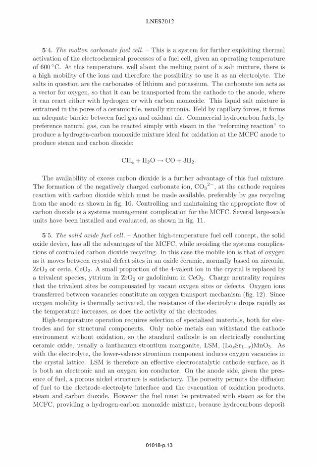
5.1. The alkaline fuel cell . – This was developed in England by Francis Bacon whodemonstrated a 5 kW, 40 cell series-connection “stack” with an efficiency of 60% usinghydrogen fuel in 1959. His development was licensed for aerospace requirements and wasapplied in the Apollo spacecraft and in the Shuttle, fig. 7. Bacon chose an alkali metalhydroxide solution, typically KOH, as electrolyte since he found with the materials andcatalysts of the time that overpotential losses were lower than with acid systems. Forspacecraft, fuel cells were an ideal solution to the power supply problems for long mannedflights such as the moon missions where use of solar cells was impracticable and standardbatteries lacked capacity. Hydrogen and oxygen were already available on board, andthe water produced in the cell supplied crew requirements.
With reference to table III, it is evident that this type of cell relies on the mobilityof the hydroxyl ion in the electrolyte. A continuous supply of water at the cathode isrequired to reduce molecular oxygen to hydroxyl. However the anode reaction producesexcess water which can be recycled to the cathode. To separate the gases the electrolyteis contained in a porous separator matrix, originally asbestos. Reagent and ion transportin an alkali fuel cell are represented in fig. 8. Although the alkaline fuel cell was used in
EPJ Web of Conferences
01018-p.8
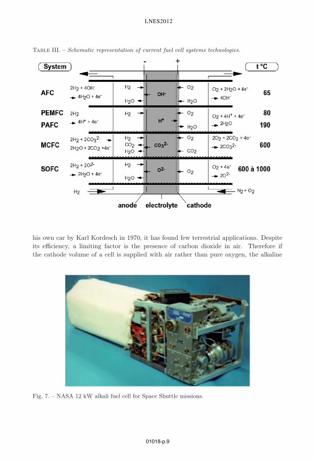
Table III. – Schematic representation of current fuel cell systems technologies.
his own car by Karl Kordesch in 1970, it has found few terrestrial applications. Despiteits efficiency, a limiting factor is the presence of carbon dioxide in air. Therefore ifthe cathode volume of a cell is supplied with air rather than pure oxygen, the alkaline
Fig. 7. – NASA 12 kW alkali fuel cell for Space Shuttle missions.
LNES2012
01018-p.9

Fig. 8. – Gas and ion transport in an AFC.
electrolyte will gradually be neutralised. In particular, potassium carbonate, K2CO3 willdeposit in the pores of the separator, deactivating the system.
5.2. The polymer electrolyte fuel cell . – The fuel cell variant currently favoured forvehicles is the polymer electrolyte (or proton exchange membrane) fuel cell, PEFC orPEMFC. Developed in the 1960’s, again for aerospace, PEFC devices actually preceededthe APC into orbit as the power source for the Gemini spacecraft. The membrane is non-permeable to molecules, and therefore acts as a separator between fuel and oxidant gases.The early cells had a short lifetime since the membrane, based on hydrocarbon, was liableto attack in the highly oxidising environment of the anode. Also, while hydrogen is easilyionised on a platinum catalyst, oxygen is much less active. To limit overpotential lossesthe early cells used a high platinum loading. The breakthrough was the introduction ofthe nafionTM fluoropolymer, in which sulfonate groups are introduced into the polymerchains. Like the related teflon, nafionTM is highly inert chemically, but the acid sitesprovide a transport mechanism for ions. Much higher platinum dispersion on carbonfibre electrodes, attached by thermocompression bonding to the electrolyte to provide arugged membrane-electrolyte assembly or MEA, make present-day PEFC systems muchmore reliable and economically attractive.
However, like the AFC, there are drawbacks. Figure 9 shows the mobile ion as H+. Infact, given the small size of that ion, its affinity for polar molecules is high and it is gener-ally associated with one or more water molecules, making a hydronium ion, H3O+. As aresult, the operating temperature of the cell is limited to < 100 ◦C. Also the ion currentalso transports water from anode to cathode. If any part of the electrolyte is deprived ofwater, local heating quickly degrades it leading to cell failure. In addition the catalystis highly sensitive to the presence of carbon monoxide, in concentrations of parts per
EPJ Web of Conferences
01018-p.10

Fig. 9. – Gas and ion transport in a PEFC.
million. Since commercial hydrogen is normally produced from natural gas, some tracepresence of CO is inevitable. While this can be minimised by selective oxidation to CO2
or reduction to CH4 the process is not simple or inexpensive. In practice the preferredfuel for PEFC is therefore electrolytic hydrogen, and a closed system results: electrolysisto produce the fuel, then the PEFC to consume it for electricity production. This is onlyjustifiable for particular applications, for example a fixed electrolyser producing storablehydrogen for a vehicle, or “renewable” electricity being stored as hydrogen for night orlow-wind recovery.
A variant of the PEFC is the direct methanol cell, DMFC. Here a liquid fuel, inprinciple “renewable”, is directly oxidised to water and carbon dioxide on a MEA. Itslimitations are the low current density available, and the fact that NafionTM is nottotally impermeable to methanol, creating a “chemical short circuit” of the cell whichsignificantly lowers the output voltage and efficiency. This cell may find some role inpowering portable electronics, for example, but it cannot provide the power density fora practical road vehicle.
5.3. The phosphoric acid fuel cell . – This concept was favoured for some time, since itdoes not have the temperature limitation of the PEFC system. With the high affinity ofthe acid for water, the cell can remain humidified up to 200 ◦C. The catalyst is thereforethermally activated, and the tolerance to carbon monoxide is significantly increased. Pre-treatment of hydrocarbon fuel such as natural gas is greatly simplified, and commercialhydrogen is an acceptable fuel. The PAFC being an acid cell, the gas and ion transportprocesses are analogous to those of the PEFC, fig. 9. However the elevated temperatureacid environment is corrosive, the degradation being enhanced by gas cavitation at the
LNES2012
01018-p.11

Fig. 10. – Gas and ion transport in a MCFC. Note the recycling of carbon dioxide from anodeto cathode as required for the formation of the ionic oxygen vector, the carbonate ion.
electrode structures. Given these limitations, PAFC development and implementationare practically at a standstill.
Fig. 11. – MCFC unit rated at 240 kW electrical output, as presented at the Hanover Fair, 2006.
EPJ Web of Conferences
01018-p.12
5.4. The molten carbonate fuel cell . – This is a system for further exploiting thermalactivation of the electrochemical processes of a fuel cell, given an operating temperatureof 600 ◦C. At this temperature, well about the melting point of a salt mixture, there isa high mobility of the ions and therefore the possibility to use it as an electrolyte. Thesalts in question are the carbonates of lithium and potassium. The carbonate ion acts asa vector for oxygen, so that it can be transported from the cathode to the anode, whereit can react either with hydrogen or with carbon monoxide. This liquid salt mixture isentrained in the pores of a ceramic tile, usually zirconia. Held by capillary forces, it formsan adequate barrier between fuel gas and oxidant air. Commercial hydrocarbon fuels, bypreference natural gas, can be reacted simply with steam in the “reforming reaction” toproduce a hydrogen-carbon monoxide mixture ideal for oxidation at the MCFC anode toproduce steam and carbon dioxide:
CH4 + H2O → CO + 3H2.
The availability of excess carbon dioxide is a further advantage of this fuel mixture.The formation of the negatively charged carbonate ion, CO3
2−, at the cathode requiresreaction with carbon dioxide which must be made available, preferably by gas recyclingfrom the anode as shown in fig. 10. Controlling and maintaining the appropriate flow ofcarbon dioxide is a systems management complication for the MCFC. Several large-scaleunits have been installed and evaluated, as shown in fig. 11.
5.5. The solid oxide fuel cell . – Another high-temperature fuel cell concept, the solidoxide device, has all the advantages of the MCFC, while avoiding the systems complica-tions of controlled carbon dioxide recycling. In this case the mobile ion is that of oxygenas it moves between crystal defect sites in an oxide ceramic, normally based on zirconia,ZrO2 or ceria, CeO2. A small proportion of the 4-valent ion in the crystal is replaced bya trivalent species, yttrium in ZrO2 or gadolinium in CeO2. Charge neutrality requiresthat the trivalent sites be compensated by vacant oxygen sites or defects. Oxygen ionstransferred between vacancies constitute an oxygen transport mechanism (fig. 12). Sinceoxygen mobility is thermally activated, the resistance of the electrolyte drops rapidly asthe temperature increases, as does the activity of the electrodes.
High-temperature operation requires selection of specialised materials, both for elec-trodes and for structural components. Only noble metals can withstand the cathodeenvironment without oxidation, so the standard cathode is an electrically conductingceramic oxide, usually a lanthanum-strontium manganite, LSM, (LaxSr1−x)MnO3. Aswith the electrolyte, the lower-valence strontium component induces oxygen vacancies inthe crystal lattice. LSM is therefore an effective electrocatalytic cathode surface, as itis both an electronic and an oxygen ion conductor. On the anode side, given the pres-ence of fuel, a porous nickel structure is satisfactory. The porosity permits the diffusionof fuel to the electrode-electrolyte interface and the evacuation of oxidation products,steam and carbon dioxide. However the fuel must be pretreated with steam as for theMCFC, providing a hydrogen-carbon monoxide mixture, because hydrocarbons deposit
LNES2012
01018-p.13

Fig. 12. – Gas and ion transport in a SOFC.
carbon on the metal, blocking the porosity and even disrupting the structure. Also atelevated temperatures and under reducing conditions, porous nickel tends to sinter, afurther mechanism to close off porosity. The practical anode now used is a cermet, a
Fig. 13. – Prototype 220 kWe combined cycle SOFC/steam turbine generator set. The press-surised enclosure for the fuel cell is in the foreground.
EPJ Web of Conferences
01018-p.14

composite structure of fine-grain nickel and zirconia, which has a demonstrated stabilitywith porosity maintained for the operational lifetime of the SOFC system. Obviouslyalso, very high-temperature systems must be carefully insulated, and heat managementis a challenge, involving heat recovery from the exhaust gas for the fuel processing step.There has also been a demonstration of a combined cycle plant, where recovered heatraises steam for a turbogenerator set (fig. 13). A significant application opportunity is fora home-scale combined heat and power (CHP)device, providing a few kW of electricitywhile also supplying the heating and hot water requirements of the occupants.
6. – Present status of fuel cells
The principal concepts for the realisation of fuel cell generating systems have beenpresented, and it is clear that while each has its specific advantages there are also factorswhich severely limit applications. The low-temperature cells are obviously more adaptedto portable and mobile use, but present very severe electrocatalysis requirements, requir-ing materials with, unfortunately, high sensitivity to fuel impurities. They are flexible,with rapid start-up times, fast response to changing electrical demands, compact witha reasonable power density and therefore compatible with vehicle drive trains, quietand increasingly reliable. Fuel cell powered cars, buses and other vehicles have beendemonstrated. The limitation is the availability of an infrastructure able to supply fuelcell quality hydrogen with the same convenience as regular motor fuel. In consequencethere is no large-scale manufacture of low temperature fuel cells.
There is a similar situation for the high-temperature devices. The concepts are proven,but the materials required are specialised, and the systems comprising the balance ofplant such as fuel processing, sensors, control, and thermal balance are complex. Theapplications foreseen are for fixed installations. On the domestic scale a CHP mustbe fully automated and fail-safe, with low maintenance demands and sufficiently lowcost to compete effectively with conventional systems for home electrical and thermalrequirements. Prototype units have been demonstrated, but their high efficiency doesnot yet justify the investment and long-term reliability remains to be established. Onan industrial scale large SOFC generator sets face similar problems. With the ancillarysystems they are much larger than equivalent electromechanical units. Some progress isevident, with 200 kWe units being on commercial offer from Bloom Energy, USA. Costand operational experience including personnel training are still inhibiting factors.
It could be suggested that niche markets should be developed, so that the fuel celloperation can be established as practical and economically advantageous, with a gain offabrication and operating experience. A prime example is the recent commissioning ofa 1 MWe fuel cell unit at the Antwerp plant of the Belgian chemical company Solvay.Large-scale brine electrolysis is carried out to provide chlorine for PVC manufacture; fuelcell quality hydrogen is a by-product with which the fuel cell can generate electricity.
LNES2012
01018-p.15

7. – Conclusion
This review has focussed on fuel cells as an example of an electrochemical-energyproduction process, presenting it in its historical context and taking into account therecent emphasis on research and development of energy conversion systems. Primaryand secondary batteries are another energy-related area, and the recent breakthroughsin lithium cells with their unprecedented energy and current densities are not to beoverlooked. Transient energy storage can be associated with electrolytic supercapaciitors.Solar-energy conversion with dye-sensitised photoelectrochemical cells is in competitionwith conventional solid state photovoltaics, providing a stimulus to improvement of bothconcepts. Then there is the issue of energy conservation in industrial electrochemicalsystems, including electrochemical metallurgy. The carbon anode of a Hall-Herault cellfor aluminium production can be regarded as a fuel cell, since with its oxidation tocarbon dioxide the potential required by the cell is reduced by 1V, minimising fluorineemissions from the elecrolyte. Obviously then there are increasing opportunities forelectrochemistry to contribute to our energy economy and to environmentally favourableindustrial processes. Despite that, it must be admitted that we are still far from realisingOstwald’s vision of a combustion-free world.
Further reading
– Shukla A. K. and Kumar P. T., Pillars of Modern Electrochemistry, Elec-trochem. Soc. Interface, 17 (2008) 31.http://electrochem.cwru.edu/encycl/art-p05-pillars-of-ec.htm
– Hamann C. H., Hamnett A. and Vielstich W., Electrochemistry (Wiley-VCH,Weinheim, DE) 2007, ISBN 978-3-527-31069-2.
– Lefrou C., Fabry P. and Poignet J.-C., Electrochemistry (Springer, Heidel-berg) 2012, ISBN 978-3-642-30250-3.
– O’Hayre R., Cha S.-W., Colella W. and Prinz F. B., Fuel Cell Fundamen-tals, 2nd edition (Wiley, New York) 2009, ISBN 978-0-470-25843-9.
EPJ Web of Conferences
01018-p.16