fundamentals of direct current circuits - ced engineering of dc... · fundamentals of direct...
TRANSCRIPT
Fundamentals of Direct Current Circuits Course No: E06-001
Credit: 6 PDH
A. Bhatia
Continuing Education and Development, Inc. 9 Greyridge Farm Court Stony Point, NY 10980 P: (877) 322-5800 F: (877) 322-4774 [email protected]
3-1
CHAPTER 3
DIRECT CURRENT
LEARNING OBJECTIVES
Upon completing this chapter, you will be able to:
1. Identify the term schematic diagram and identify the components in a circuit from a simpleschematic diagram.
2. State the equation for Ohm’s law and describe the effects on current caused by changes in acircuit.
3. Given simple graphs of current versus power and voltage versus power, determine the value ofcircuit power for a given current and voltage.
4. Identify the term power, and state three formulas for computing power.
5. Compute circuit and component power in series, parallel, and combination circuits.
6. Compute the efficiency of an electrical device.
7. Solve for unknown quantities of resistance, current, and voltage in a series circuit.
8. Describe how voltage polarities are assigned to the voltage drops across resistors whenKirchhoff’s voltage law is used.
9. State the voltage at the reference point in a circuit.
10. Define open and short circuits and describe their effects on a circuit.
11. State the meaning of the term source resistance and describe its effect on a circuit.
12. Describe in terms of circuit values the circuit condition needed for maximum power transfer.
13. Compute efficiency of power transfer in a circuit.
14. Solve for unknown quantities of resistance, current, and voltage in a parallel circuit.
15. State the significance of the polarity assigned to a current when using Kirchhoff’s current law.
16. State the meaning of the term equivalent resistance.
17. Compute resistance, current, voltage, and power in voltage dividers.
18. Describe the method by which a single voltage divider can provide both positive and negativevoltages.
19. Recognize the safety precautions associated with the hazard of electrical shock.
20. Identify the first aid procedures for a victim of electrical shock.
3-2
INTRODUCTION
The material covered in this chapter contains many new terms that are explained as you progressthrough the material. The basic dc circuit is the easiest to understand, so the chapter begins with the basiccircuit and from there works into the basic schematic diagram of that circuit. The schematic diagram isused in all your future work in electricity and electronics. It is very important that you become familiarwith the symbols that are used.
This chapter also explains how to determine the total resistance, current, voltage, and power in aseries, parallel, or combination circuit through the use of Ohm’s and Kirchhoff’s laws. The voltage dividernetwork, series, parallel, and series-parallel practice problem circuits will be used for practical examplesof what you have learned.
THE BASIC ELECTRIC CIRCUIT
The flashlight is an example of a basic electric circuit. It contains a source of electrical energy (thedry cells in the flashlight), a load (the bulb) which changes the electrical energy into a more useful formof energy (light), and a switch to control the energy delivered to the load.
Before you study a schematic representation of the flashlight, it is necessary to define certain terms.The LOAD is any device through which an electrical current flows and which changes this electricalenergy into a more useful form. Some common examples of loads are a lightbulb, which changeselectrical energy to light energy; an electric motor, which changes electrical energy into mechanicalenergy; and the speaker in a radio, which changes electrical energy into sound. The SOURCE is thedevice which furnishes the electrical energy used by the load. It may consist of a simple dry cell (as in aflashlight), a storage battery (as in an automobile), or a power supply (such as a battery charger). TheSWITCH, which permits control of the electrical device, interrupts the current delivered to the load.
SCHEMATIC REPRESENTATION
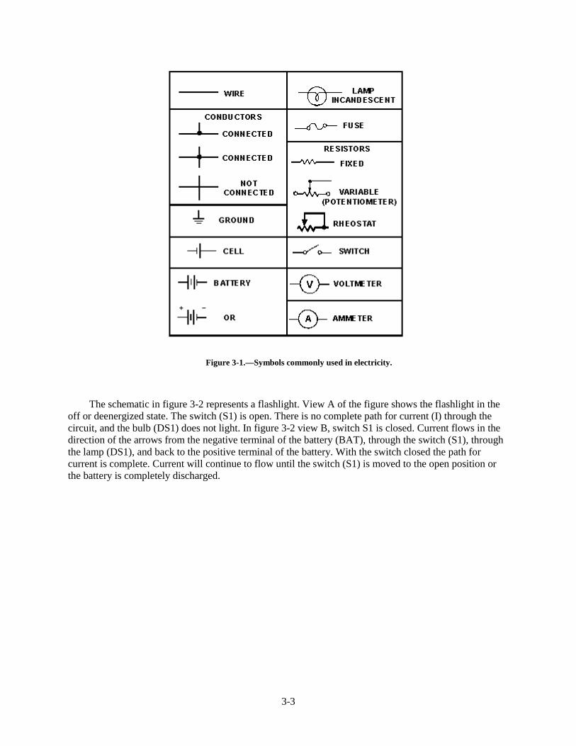
The technician’s main aid in troubleshooting a circuit in a piece of equipment is the SCHEMATICDIAGRAM. The schematic diagram is a "picture" of the circuit that uses symbols to represent the variouscircuit components; physically large or complex circuits can be shown on a relatively small diagram.Before studying the basic schematic, look at figure 3-1. This figure shows the symbols that are used inthis chapter. These, and others like them, are referred to and used throughout the study of electricity andelectronics.
3-3
Figure 3-1.—Symbols commonly used in electricity.
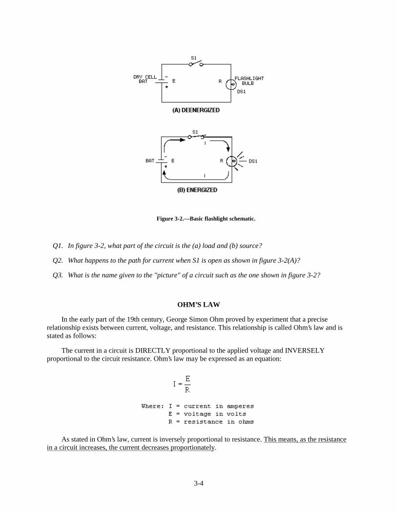
The schematic in figure 3-2 represents a flashlight. View A of the figure shows the flashlight in theoff or deenergized state. The switch (S1) is open. There is no complete path for current (I) through thecircuit, and the bulb (DS1) does not light. In figure 3-2 view B, switch S1 is closed. Current flows in thedirection of the arrows from the negative terminal of the battery (BAT), through the switch (S1), throughthe lamp (DS1), and back to the positive terminal of the battery. With the switch closed the path forcurrent is complete. Current will continue to flow until the switch (S1) is moved to the open position orthe battery is completely discharged.
3-4
Figure 3-2.—Basic flashlight schematic.
Q1. In figure 3-2, what part of the circuit is the (a) load and (b) source?
Q2. What happens to the path for current when S1 is open as shown in figure 3-2(A)?
Q3. What is the name given to the "picture" of a circuit such as the one shown in figure 3-2?
OHM’S LAW
In the early part of the 19th century, George Simon Ohm proved by experiment that a preciserelationship exists between current, voltage, and resistance. This relationship is called Ohm’s law and isstated as follows:
The current in a circuit is DIRECTLY proportional to the applied voltage and INVERSELYproportional to the circuit resistance. Ohm’s law may be expressed as an equation:
As stated in Ohm’s law, current is inversely proportional to resistance. This means, as the resistancein a circuit increases, the current decreases proportionately.
3-5
In the equation
if any two quantities are known, the third one can be determined. Refer to figure 3-2(B), theschematic of the flashlight. If the battery (BAT) supplies a voltage of 1.5 volts and the lamp (DS1) has aresistance of 5 ohms, then the current in the circuit can be determined. Using this equation andsubstituting values:
If the flashlight were a two-cell flashlight, we would have twice the voltage, or 3.0 volts, applied tothe circuit. Using this voltage in the equation:
You can see that the current has doubled as the voltage has doubled. This demonstrates that thecurrent is directly proportional to the applied voltage.
If the value of resistance of the lamp is doubled, the equation will be:
The current has been reduced to one half of the value of the previous equation, or .3 ampere. Thisdemonstrates that the current is inversely proportional to the resistance. Doubling the value of theresistance of the load reduces circuit current value to one half of its former value.
APPLICATION OF OHM’S LAW
By using Ohm’s law, you are able to find the resistance of a circuit, knowing only the voltage and thecurrent in the circuit.
In any equation, if all the variables (parameters) are known except one, that unknown can be found.For example, using Ohm’s law, if current (I) and voltage (E) are known, resistance (R) the only parameternot known, can be determined:
1. Basic formula:
2. Remove the divisor by multiplying both sides by R:
3-6
3. Result of step 2: R x I = E
4. To get R alone (on one side of the equation) divide both sides by I:
5. The basic formula, transposed for R, is:
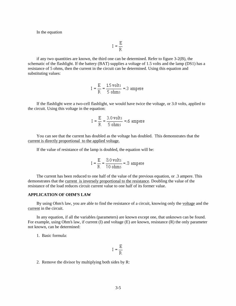
Refer to figure 3-3 where E equals 10 volts and I equals 1 ampere. Solve for R, using the equationjust explained.
Given: E = 10 volts
I = 1 ampere
Solution:
Figure 3-3.—Determining resistance in a basic circuit.
3-7
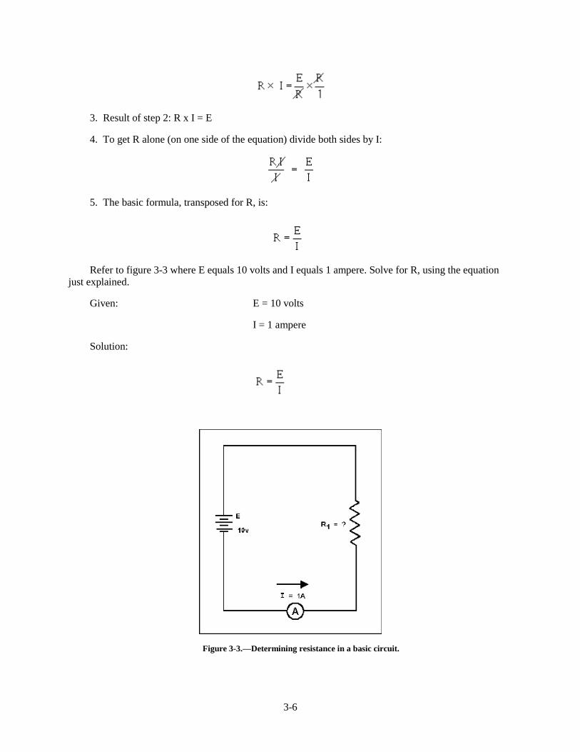
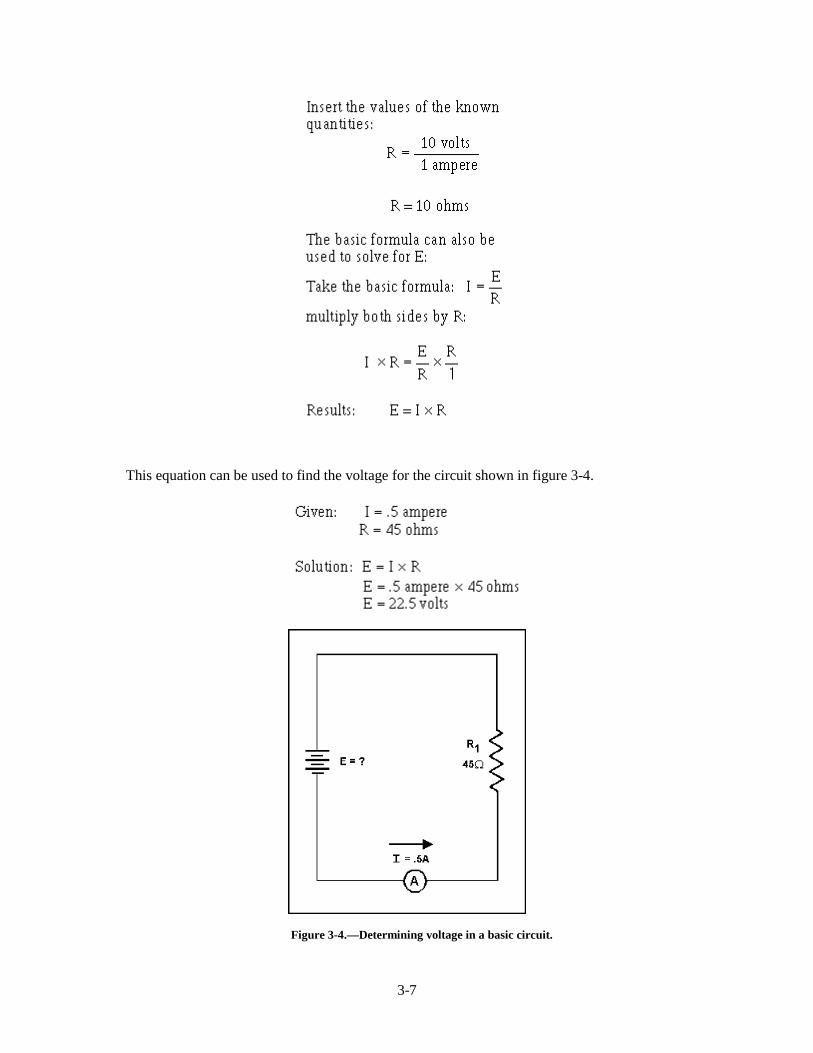
This equation can be used to find the voltage for the circuit shown in figure 3-4.
Figure 3-4.—Determining voltage in a basic circuit.
3-8
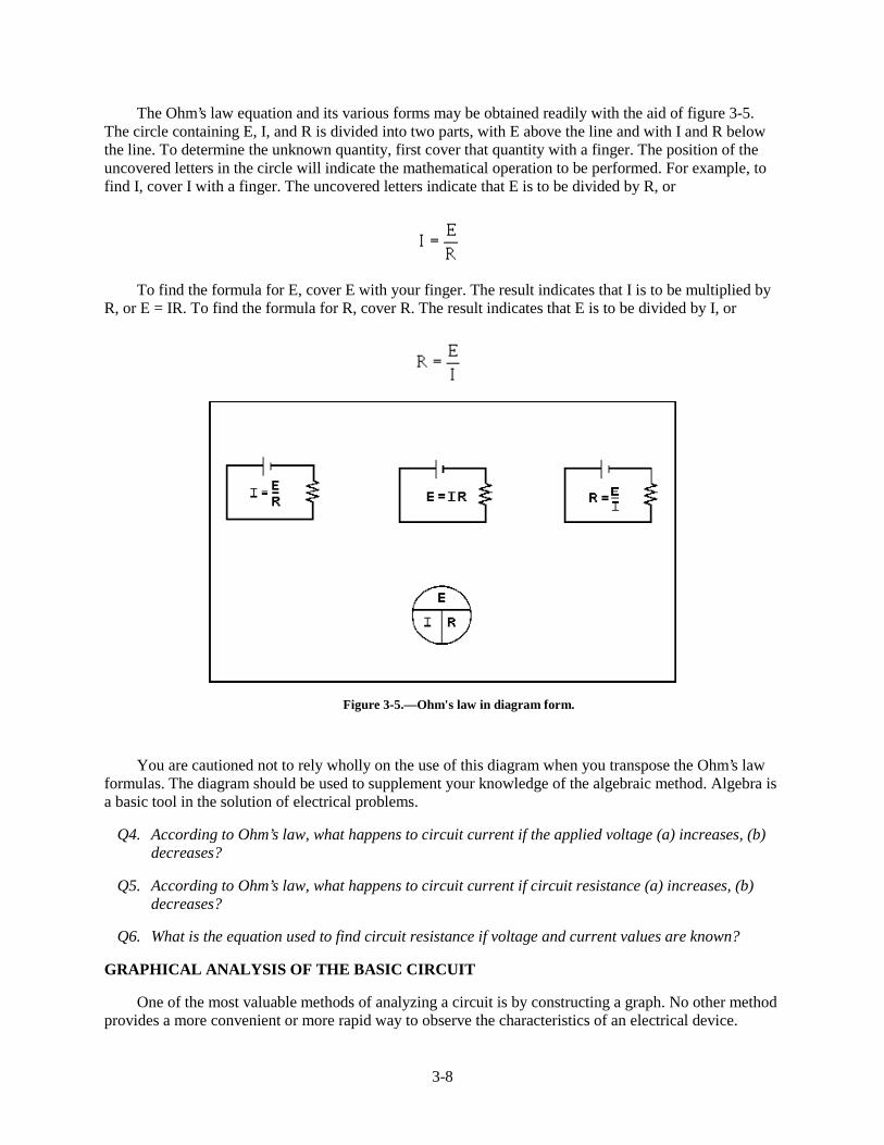
The Ohm’s law equation and its various forms may be obtained readily with the aid of figure 3-5.The circle containing E, I, and R is divided into two parts, with E above the line and with I and R belowthe line. To determine the unknown quantity, first cover that quantity with a finger. The position of theuncovered letters in the circle will indicate the mathematical operation to be performed. For example, tofind I, cover I with a finger. The uncovered letters indicate that E is to be divided by R, or
To find the formula for E, cover E with your finger. The result indicates that I is to be multiplied byR, or E = IR. To find the formula for R, cover R. The result indicates that E is to be divided by I, or
Figure 3-5.—Ohm's law in diagram form.
You are cautioned not to rely wholly on the use of this diagram when you transpose the Ohm’s lawformulas. The diagram should be used to supplement your knowledge of the algebraic method. Algebra isa basic tool in the solution of electrical problems.
Q4. According to Ohm’s law, what happens to circuit current if the applied voltage (a) increases, (b)decreases?
Q5. According to Ohm’s law, what happens to circuit current if circuit resistance (a) increases, (b)decreases?
Q6. What is the equation used to find circuit resistance if voltage and current values are known?
GRAPHICAL ANALYSIS OF THE BASIC CIRCUIT
One of the most valuable methods of analyzing a circuit is by constructing a graph. No other methodprovides a more convenient or more rapid way to observe the characteristics of an electrical device.
3-9
The first step in constructing a graph is to obtain a table of data. The information in the table can beobtained by taking measurements on the circuit under examination, or can be obtained theoreticallythrough a series of Ohm’s law computations. The latter method is used here.
Since there are three variables (E, I, and R) to be analyzed, there are three distinct graphs that maybe constructed.
To construct any graph of electrical quantities, it is standard practice to vary one quantity in aspecified way and note the changes which occur in a second quantity. The quantity which is intentionallyvaried is called the independent variable and is plotted on the horizontal axis. The horizontal axis isknown as the X-AXIS. The second quantity, which varies as a result of changes in the first quantity, iscalled the dependent variable and is plotted on the vertical, or Y-AXIS. Any other quantities involved areheld constant.
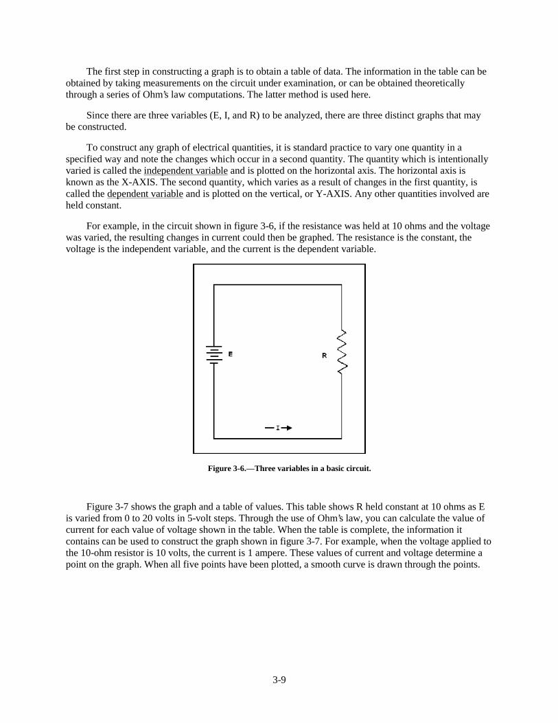
For example, in the circuit shown in figure 3-6, if the resistance was held at 10 ohms and the voltagewas varied, the resulting changes in current could then be graphed. The resistance is the constant, thevoltage is the independent variable, and the current is the dependent variable.
Figure 3-6.—Three variables in a basic circuit.
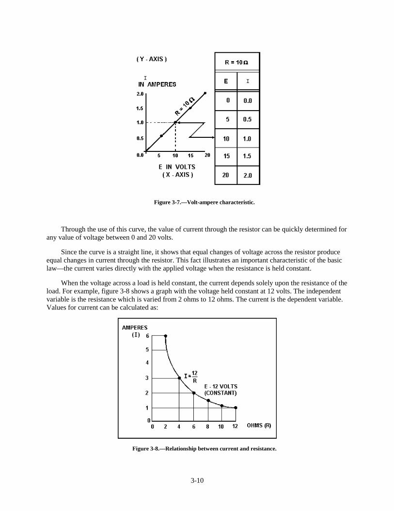
Figure 3-7 shows the graph and a table of values. This table shows R held constant at 10 ohms as Eis varied from 0 to 20 volts in 5-volt steps. Through the use of Ohm’s law, you can calculate the value ofcurrent for each value of voltage shown in the table. When the table is complete, the information itcontains can be used to construct the graph shown in figure 3-7. For example, when the voltage applied tothe 10-ohm resistor is 10 volts, the current is 1 ampere. These values of current and voltage determine apoint on the graph. When all five points have been plotted, a smooth curve is drawn through the points.
3-10
Figure 3-7.—Volt-ampere characteristic.
Through the use of this curve, the value of current through the resistor can be quickly determined forany value of voltage between 0 and 20 volts.
Since the curve is a straight line, it shows that equal changes of voltage across the resistor produceequal changes in current through the resistor. This fact illustrates an important characteristic of the basiclaw—the current varies directly with the applied voltage when the resistance is held constant.
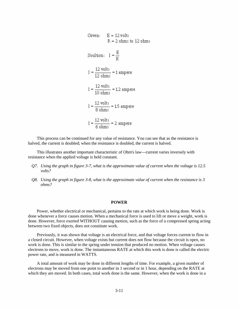
When the voltage across a load is held constant, the current depends solely upon the resistance of theload. For example, figure 3-8 shows a graph with the voltage held constant at 12 volts. The independentvariable is the resistance which is varied from 2 ohms to 12 ohms. The current is the dependent variable.Values for current can be calculated as:
Figure 3-8.—Relationship between current and resistance.
3-11
This process can be continued for any value of resistance. You can see that as the resistance ishalved, the current is doubled; when the resistance is doubled, the current is halved.
This illustrates another important characteristic of Ohm's law—current varies inversely withresistance when the applied voltage is held constant.
Q7. Using the graph in figure 3-7, what is the approximate value of current when the voltage is 12.5volts?
Q8. Using the graph in figure 3-8, what is the approximate value of current when the resistance is 3ohms?
POWER
Power, whether electrical or mechanical, pertains to the rate at which work is being done. Work isdone whenever a force causes motion. When a mechanical force is used to lift or move a weight, work isdone. However, force exerted WITHOUT causing motion, such as the force of a compressed spring actingbetween two fixed objects, does not constitute work.
Previously, it was shown that voltage is an electrical force, and that voltage forces current to flow ina closed circuit. However, when voltage exists but current does not flow because the circuit is open, nowork is done. This is similar to the spring under tension that produced no motion. When voltage causeselectrons to move, work is done. The instantaneous RATE at which this work is done is called the electricpower rate, and is measured in WATTS.
A total amount of work may be done in different lengths of time. For example, a given number ofelectrons may be moved from one point to another in 1 second or in 1 hour, depending on the RATE atwhich they are moved. In both cases, total work done is the same. However, when the work is done in a
3-12
short time, the wattage, or INSTANTANEOUS POWER RATE, is greater than when the same amount ofwork is done over a longer period of time.
As stated, the basic unit of power is the watt. Power in watts is equal to the voltage across a circuitmultiplied by current through the circuit. This represents the rate at any given instant at which work isbeing done. The symbol P indicates electrical power. Thus, the basic power formula is P = E x I, where Eis voltage and I is current in the circuit. The amount of power changes when either voltage or current, orboth voltage and current, are caused to change.
In practice, the ONLY factors that can be changed are voltage and resistance. In explaining thedifferent forms that formulas may take, current is sometimes presented as a quantity that is changed.Remember, if current is changed, it is because either voltage or resistance has been changed.
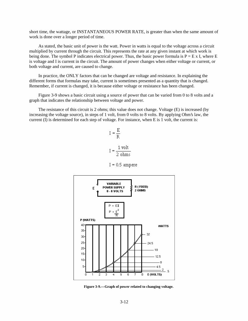
Figure 3-9 shows a basic circuit using a source of power that can be varied from 0 to 8 volts and agraph that indicates the relationship between voltage and power.
The resistance of this circuit is 2 ohms; this value does not change. Voltage (E) is increased (byincreasing the voltage source), in steps of 1 volt, from 0 volts to 8 volts. By applying Ohm’s law, thecurrent (I) is determined for each step of voltage. For instance, when E is 1 volt, the current is:
Figure 3-9.—Graph of power related to changing voltage.
3-13
Power (P), in watts, is determined by applying the basic power formula:
and
P = E x I
P = 2 volts x 1 ampere
P = 2 watts
You should notice that when the voltage was increased to 2 volts, the power increased from .5 wattsto 2 watts or 4 times. When the voltage increased to 3 volts, the power increased to 4.5 watts or 9 times.This shows that if the resistance in a circuit is held constant, the power varies directly with the SQUAREOF THE VOLTAGE.
Another way of proving that power varies as the square of the voltage when resistance is heldconstant is:
3-14
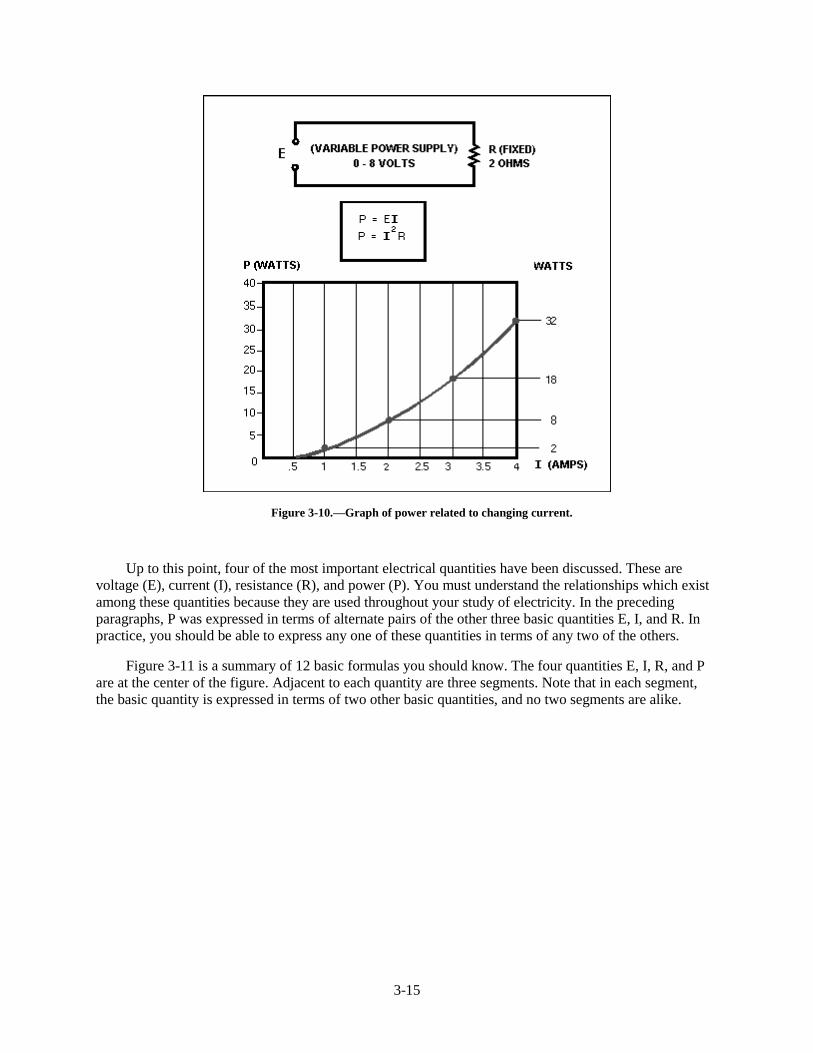
Another important relationship may be seen by studying figure 3-10. Thus far, power has beencalculated with voltage and current (P = E x I), and with voltage and resistance
Referring to figure 3-10, note that power also varies as the square of current just as it does withvoltage. Thus, another formula for power, with current and resistance as its factors, is P = I 2R. This canbe proved by:
3-15
Figure 3-10.—Graph of power related to changing current.
Up to this point, four of the most important electrical quantities have been discussed. These arevoltage (E), current (I), resistance (R), and power (P). You must understand the relationships which existamong these quantities because they are used throughout your study of electricity. In the precedingparagraphs, P was expressed in terms of alternate pairs of the other three basic quantities E, I, and R. Inpractice, you should be able to express any one of these quantities in terms of any two of the others.
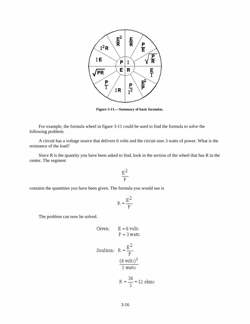
Figure 3-11 is a summary of 12 basic formulas you should know. The four quantities E, I, R, and Pare at the center of the figure. Adjacent to each quantity are three segments. Note that in each segment,the basic quantity is expressed in terms of two other basic quantities, and no two segments are alike.
3-16
Figure 3-11.—Summary of basic formulas.
For example, the formula wheel in figure 3-11 could be used to find the formula to solve thefollowing problem:
A circuit has a voltage source that delivers 6 volts and the circuit uses 3 watts of power. What is theresistance of the load?
Since R is the quantity you have been asked to find, look in the section of the wheel that has R in thecenter. The segment
contains the quantities you have been given. The formula you would use is
The problem can now be solved.
3-17
Q9. What is the term applied to the rate at which a mechanical or electrical force causes motion?
Q10. How can the amount of current be changed in a circuit?
Q11. What are the three formulas for electrical power?
POWER RATING
Electrical components are often given a power rating. The power rating, in watts, indicates the rate atwhich the device converts electrical energy into another form of energy, such as light, heat, or motion. Anexample of such a rating is noted when comparing a 150-watt lamp to a 100-watt lamp. The higherwattage rating of the 150-watt lamp indicates it is capable of converting more electrical energy into lightenergy than the lamp of the lower rating. Other common examples of devices with power ratings aresoldering irons and small electric motors.
In some electrical devices the wattage rating indicates the maximum power the device is designed touse rather than the normal operating power. A 150-watt lamp, for example, uses 150 watts when operatedat the specified voltage printed on the bulb. In contrast, a device such as a resistor is not normally given avoltage or a current rating. A resistor is given a power rating in watts and can be operated at anycombination of voltage and current as long as the power rating is not exceeded. In most circuits, the actualpower used by a resistor is considerably less than the power rating of the resistor because a 50% safetyfactor is used. For example, if a resistor normally used 2 watts of power, a resistor with a power rating of3 watts would be used.
Resistors of the same resistance value are available in different wattage values. Carbon resistors, forexample, are commonly made in wattage ratings of 1/8, 1/4, 1/2, 1, and 2 watts. The larger the physicalsize of a carbon resistor the higher the wattage rating. This is true because a larger surface area of materialradiates a greater amount of heat more easily.
When resistors with wattage ratings greater than 5 watts are needed, wirewound resistors are used.Wirewound resistors are made in values between 5 and 200 watts. Special types of wirewound resistorsare used for power in excess of 200 watts.
As with other electrical quantities, prefixes may be attached to the word watt when expressing verylarge or very small amounts of power. Some of the more common of these are the kilowatt (1,000 watts),the megawatt (1,000,000 watts), and the milliwatt (1/1,000 of a watt).
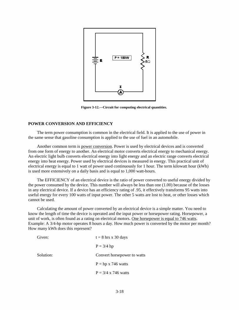
Q12. What is the current in a circuit with 5 ohms of resistance that uses 180 watts of power? (refer tofigure 3-12)
Q13. What type of resistor should be used in the circuit described in question 12?
Q14. What is the power used in a circuit that has 10 amperes of current through a 10-ohm resistor?
3-18
Figure 3-12.—Circuit for computing electrical quantities.
POWER CONVERSION AND EFFICIENCY
The term power consumption is common in the electrical field. It is applied to the use of power inthe same sense that gasoline consumption is applied to the use of fuel in an automobile.
Another common term is power conversion. Power is used by electrical devices and is convertedfrom one form of energy to another. An electrical motor converts electrical energy to mechanical energy.An electric light bulb converts electrical energy into light energy and an electric range converts electricalenergy into heat energy. Power used by electrical devices is measured in energy. This practical unit ofelectrical energy is equal to 1 watt of power used continuously for 1 hour. The term kilowatt hour (kWh)is used more extensively on a daily basis and is equal to 1,000 watt-hours.
The EFFICIENCY of an electrical device is the ratio of power converted to useful energy divided bythe power consumed by the device. This number will always be less than one (1.00) because of the lossesin any electrical device. If a device has an efficiency rating of .95, it effectively transforms 95 watts intouseful energy for every 100 watts of input power. The other 5 watts are lost to heat, or other losses whichcannot be used.
Calculating the amount of power converted by an electrical device is a simple matter. You need toknow the length of time the device is operated and the input power or horsepower rating. Horsepower, aunit of work, is often found as a rating on electrical motors. One horsepower is equal to 746 watts.Example: A 3/4-hp motor operates 8 hours a day. How much power is converted by the motor per month?How many kWh does this represent?
Given: t = 8 hrs x 30 days
P = 3/4 hp
Solution: Convert horsepower to watts
P = hp x 746 watts
P = 3/4 x 746 watts
3-19
P = 559 watts
Convert watts to watt-hours
P = work x time
P = 559 watts x 8 x 30
P = 134,000 watt-hours per month
(NOTE: These figures are rounded to the nearest 1000.)
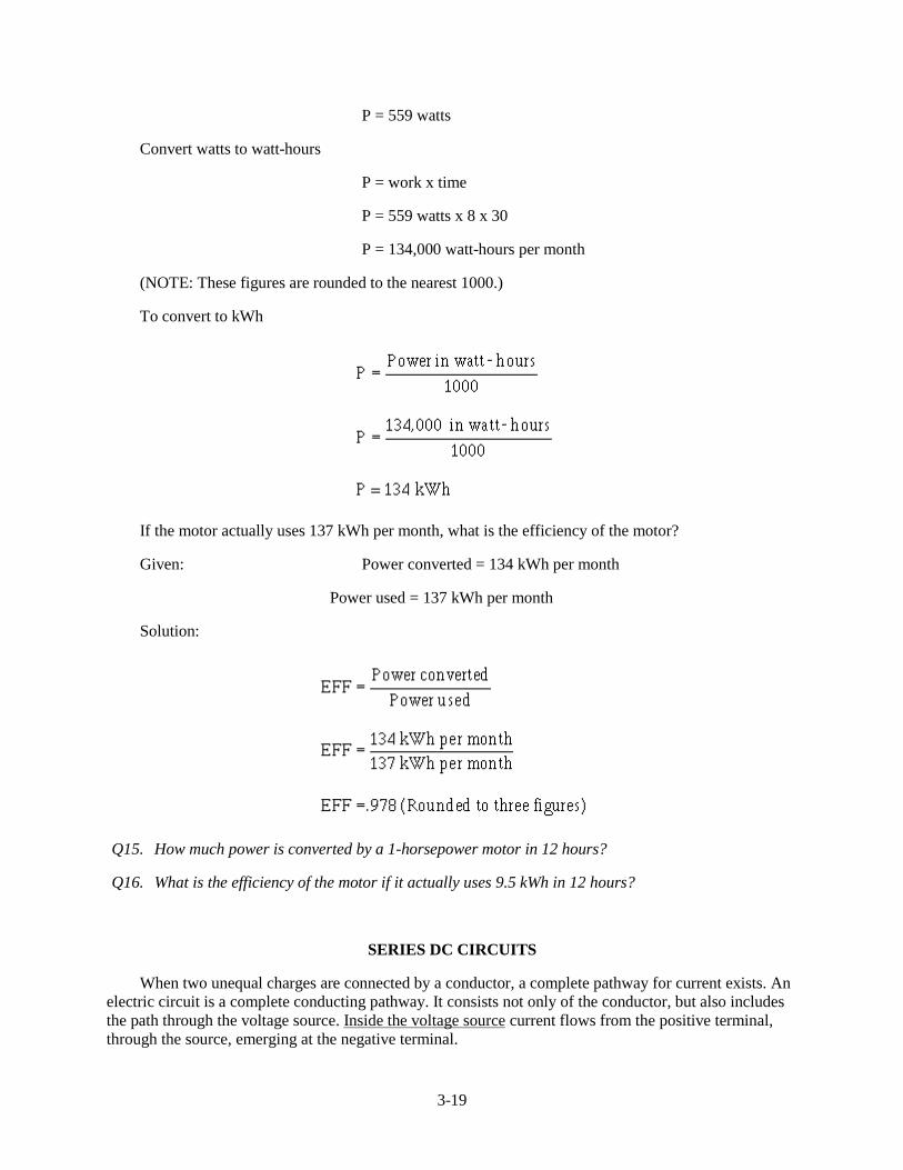
To convert to kWh
If the motor actually uses 137 kWh per month, what is the efficiency of the motor?
Given: Power converted = 134 kWh per month
Power used = 137 kWh per month
Solution:
Q15. How much power is converted by a 1-horsepower motor in 12 hours?
Q16. What is the efficiency of the motor if it actually uses 9.5 kWh in 12 hours?
SERIES DC CIRCUITS
When two unequal charges are connected by a conductor, a complete pathway for current exists. Anelectric circuit is a complete conducting pathway. It consists not only of the conductor, but also includesthe path through the voltage source. Inside the voltage source current flows from the positive terminal,through the source, emerging at the negative terminal.
3-20
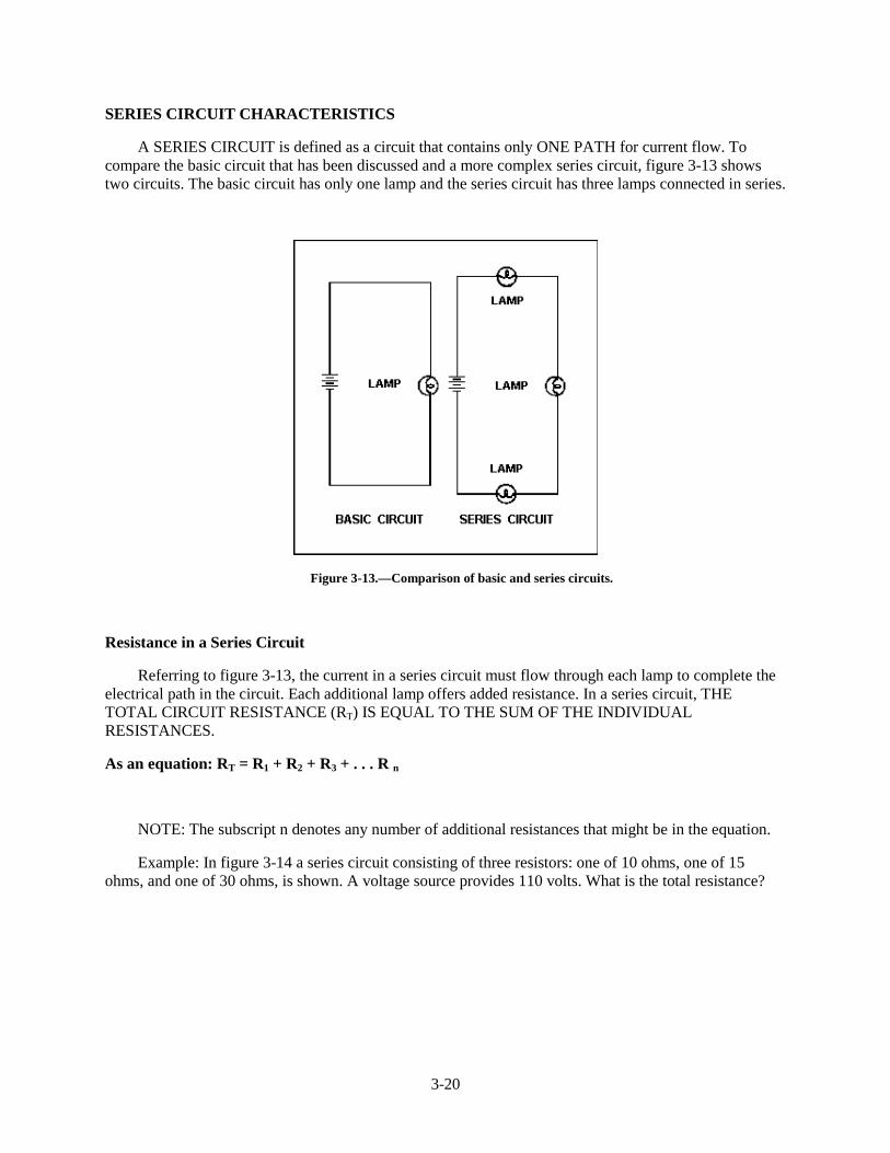
SERIES CIRCUIT CHARACTERISTICS
A SERIES CIRCUIT is defined as a circuit that contains only ONE PATH for current flow. Tocompare the basic circuit that has been discussed and a more complex series circuit, figure 3-13 showstwo circuits. The basic circuit has only one lamp and the series circuit has three lamps connected in series.
Figure 3-13.—Comparison of basic and series circuits.
Resistance in a Series Circuit
Referring to figure 3-13, the current in a series circuit must flow through each lamp to complete theelectrical path in the circuit. Each additional lamp offers added resistance. In a series circuit, THETOTAL CIRCUIT RESISTANCE (RT) IS EQUAL TO THE SUM OF THE INDIVIDUALRESISTANCES.
As an equation: RT = R1 + R2 + R3 + . . . R n
NOTE: The subscript n denotes any number of additional resistances that might be in the equation.
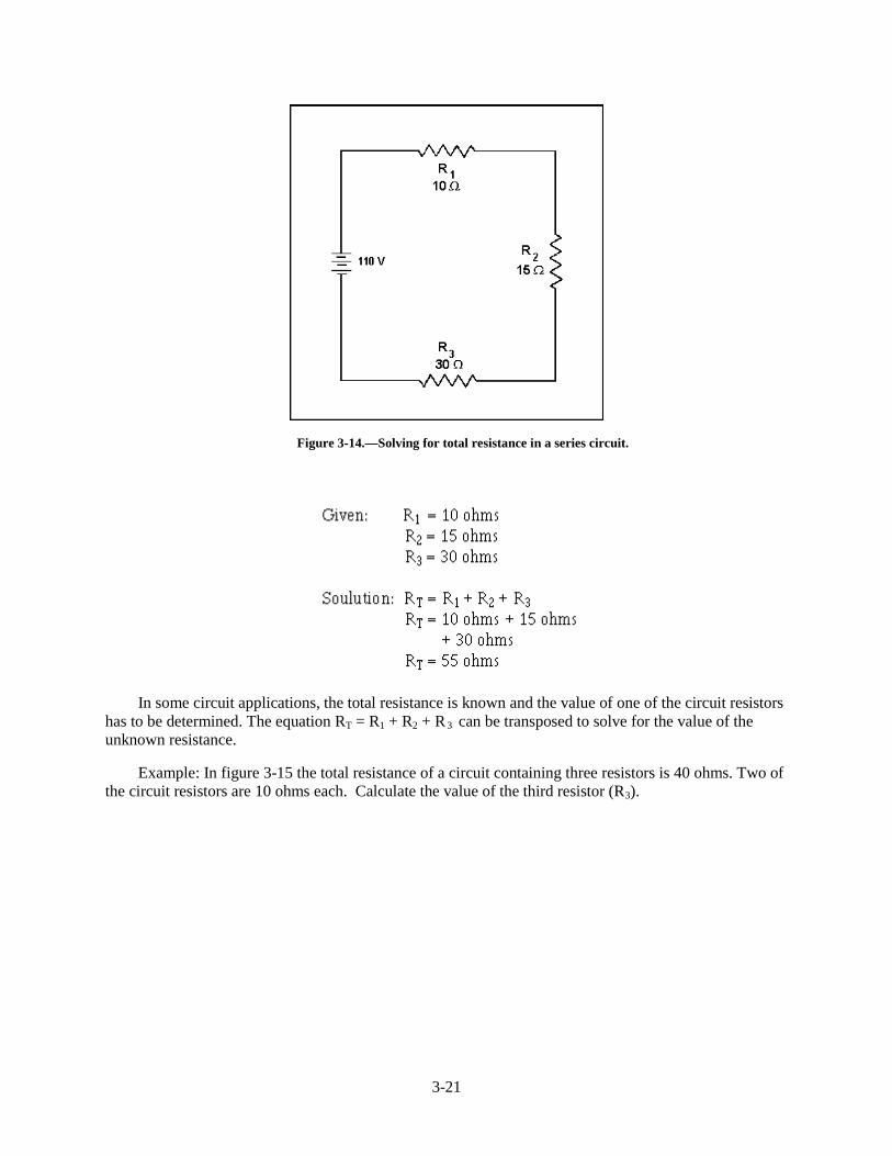
Example: In figure 3-14 a series circuit consisting of three resistors: one of 10 ohms, one of 15ohms, and one of 30 ohms, is shown. A voltage source provides 110 volts. What is the total resistance?
3-21
Figure 3-14.—Solving for total resistance in a series circuit.
In some circuit applications, the total resistance is known and the value of one of the circuit resistorshas to be determined. The equation RT = R1 + R2 + R3 can be transposed to solve for the value of theunknown resistance.
Example: In figure 3-15 the total resistance of a circuit containing three resistors is 40 ohms. Two ofthe circuit resistors are 10 ohms each. Calculate the value of the third resistor (R 3).

3-22
Figure 3-15.—Calculating the value of one resistance in a series circuit.
Current in a Series Circuit
Since there is only one path for current in a series circuit, the same current must flow through eachcomponent of the circuit. To determine the current in a series circuit, only the current through one of thecomponents need be known.
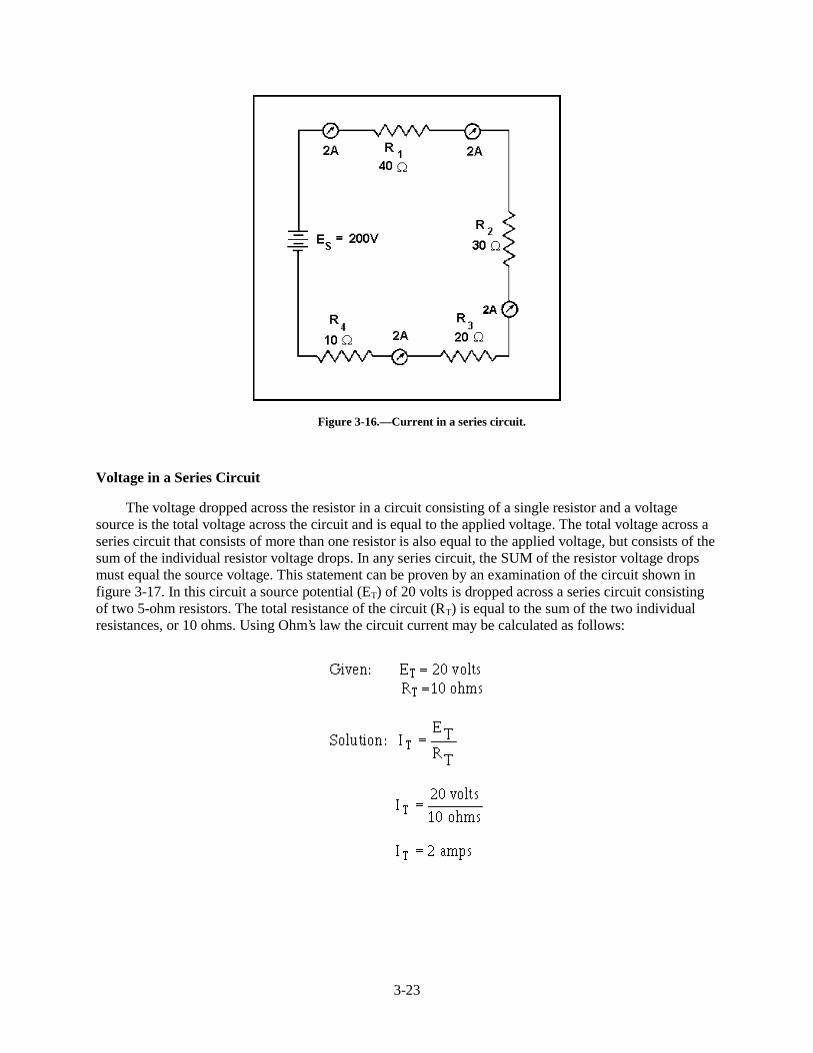
The fact that the same current flows through each component of a series circuit can be verified byinserting meters into the circuit at various points, as shown in figure 3-16. If this were done, each meterwould be found to indicate the same value of current.
3-23
Figure 3-16.—Current in a series circuit.
Voltage in a Series Circuit
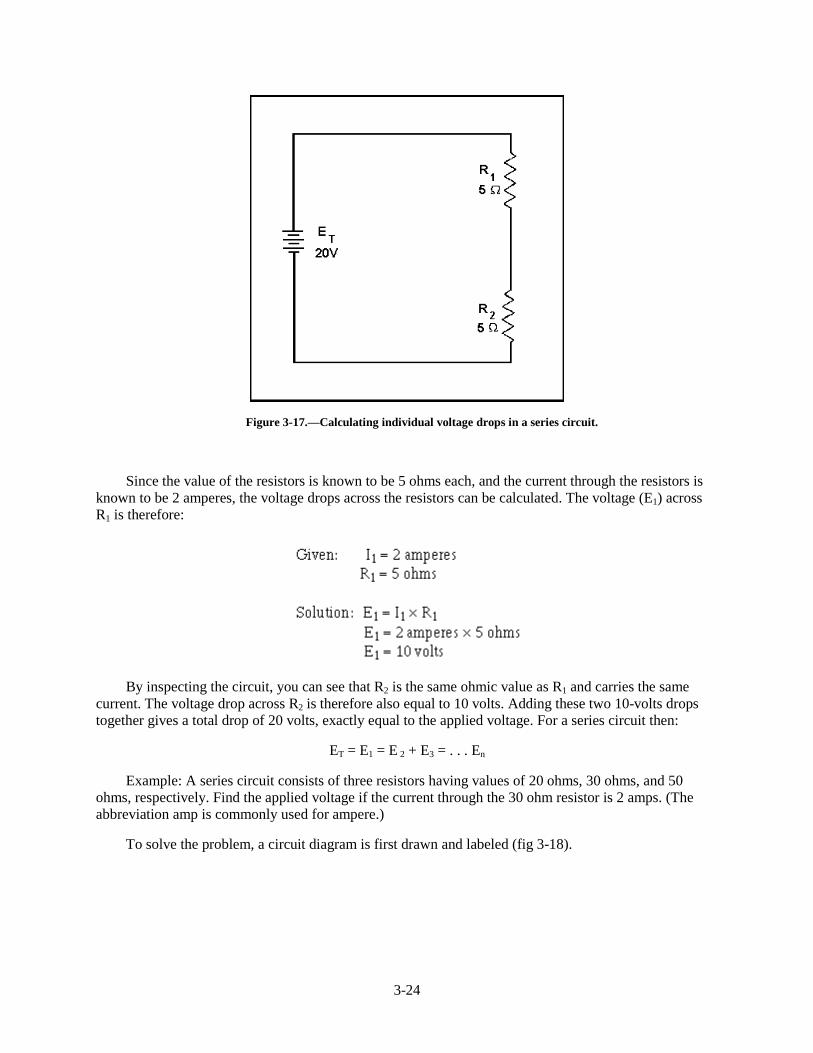
The voltage dropped across the resistor in a circuit consisting of a single resistor and a voltagesource is the total voltage across the circuit and is equal to the applied voltage. The total voltage across aseries circuit that consists of more than one resistor is also equal to the applied voltage, but consists of thesum of the individual resistor voltage drops. In any series circuit, the SUM of the resistor voltage dropsmust equal the source voltage. This statement can be proven by an examination of the circuit shown infigure 3-17. In this circuit a source potential (ET) of 20 volts is dropped across a series circuit consistingof two 5-ohm resistors. The total resistance of the circuit (RT) is equal to the sum of the two individualresistances, or 10 ohms. Using Ohm’s law the circuit current may be calculated as follows:
3-24
Figure 3-17.—Calculating individual voltage drops in a series circuit.
Since the value of the resistors is known to be 5 ohms each, and the current through the resistors isknown to be 2 amperes, the voltage drops across the resistors can be calculated. The voltage (E1) acrossR1 is therefore:
By inspecting the circuit, you can see that R2 is the same ohmic value as R1 and carries the samecurrent. The voltage drop across R2 is therefore also equal to 10 volts. Adding these two 10-volts dropstogether gives a total drop of 20 volts, exactly equal to the applied voltage. For a series circuit then:
ET = E1 = E 2 + E3 = . . . En
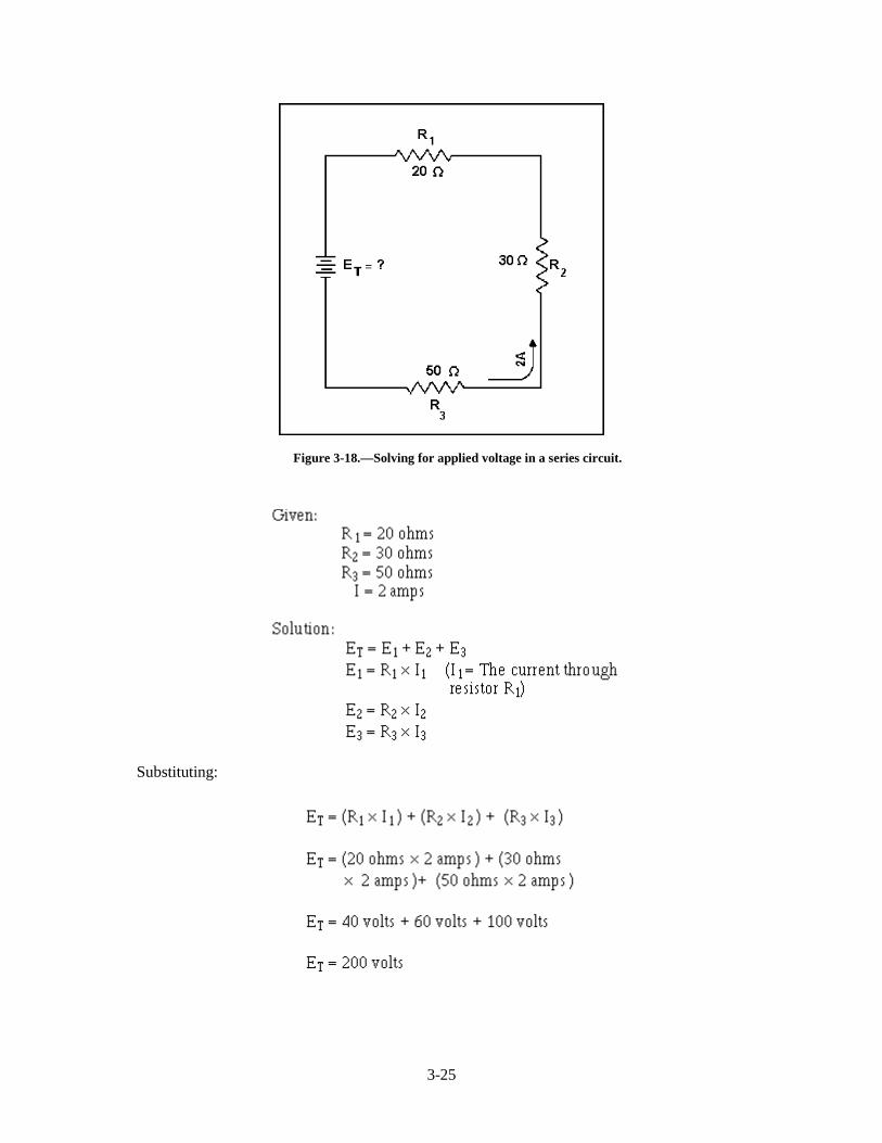
Example: A series circuit consists of three resistors having values of 20 ohms, 30 ohms, and 50ohms, respectively. Find the applied voltage if the current through the 30 ohm resistor is 2 amps. (Theabbreviation amp is commonly used for ampere.)
To solve the problem, a circuit diagram is first drawn and labeled (fig 3-18).
3-25
Figure 3-18.—Solving for applied voltage in a series circuit.
Substituting:
3-26
NOTE: When you use Ohm’s law, the quantities for the equation MUST be taken from the SAMEpart of the circuit. In the above example the voltage across R2 was computed using the current through R2
and the resistance of R2.
The value of the voltage dropped by a resistor is determined by the applied voltage and is inproportion to the circuit resistances. The voltage drops that occur in a series circuit are in directproportion to the resistances. This is the result of having the same current flow through each resistor—thelarger the ohmic value of the resistor, the larger the voltage drop across it.
Q17. A series circuit consisting of three resistors has a current of 3 amps. If R1 = 20 ohms, R2= 60ohms, and R 3 = 80 ohms, what is the (a) total resistance and (b) source voltage of the circuit?
Q18. What is the voltage dropped by each resistor of the circuit described in question 17?
Q19. If the current was increased to 4 amps, what would be the voltage drop across each resistor in thecircuit described in question 17?
Q20. What would have to be done to the circuit described in question 17 to increase the current to 4amps?
Power in a Series Circuit
Each of the resistors in a series circuit consumes power which is dissipated in the form of heat. Sincethis power must come from the source, the total power must be equal to the power consumed by thecircuit resistances. In a series circuit the total power is equal to the SUM of the power dissipated by theindividual resistors. Total power (PT) is equal to:
PT = P1 + P2 + P3 . . .Pn
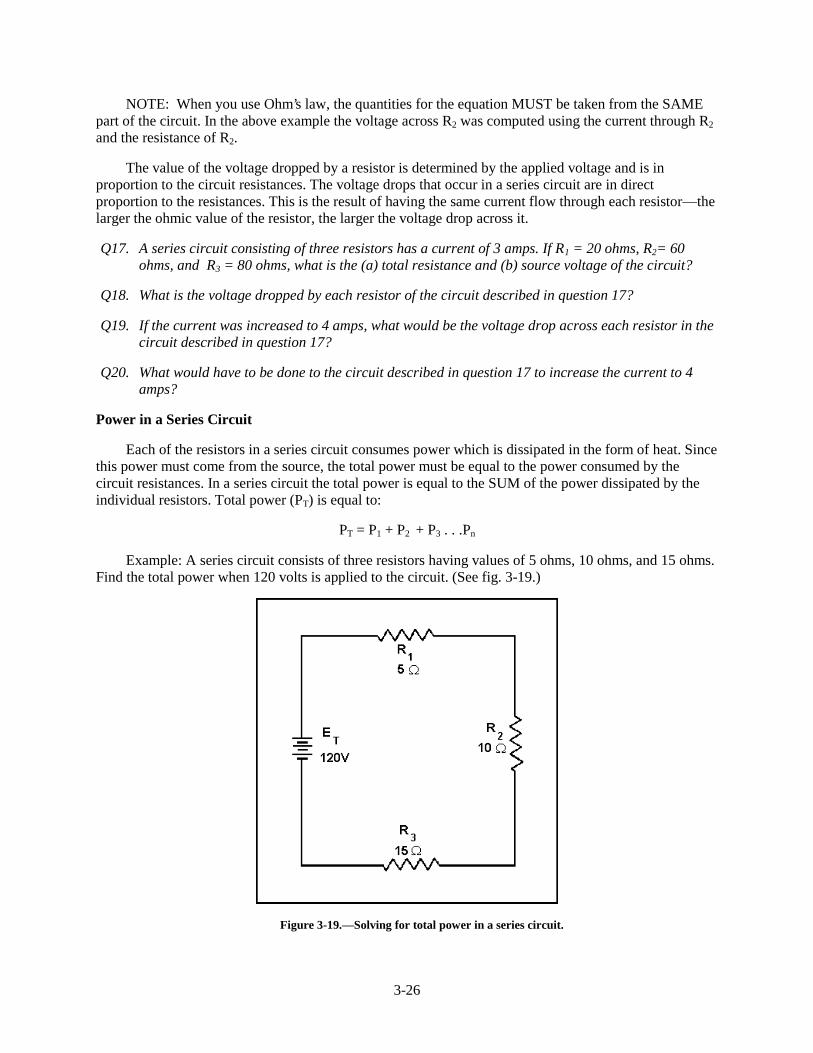
Example: A series circuit consists of three resistors having values of 5 ohms, 10 ohms, and 15 ohms.Find the total power when 120 volts is applied to the circuit. (See fig. 3-19.)
Figure 3-19.—Solving for total power in a series circuit.
3-27
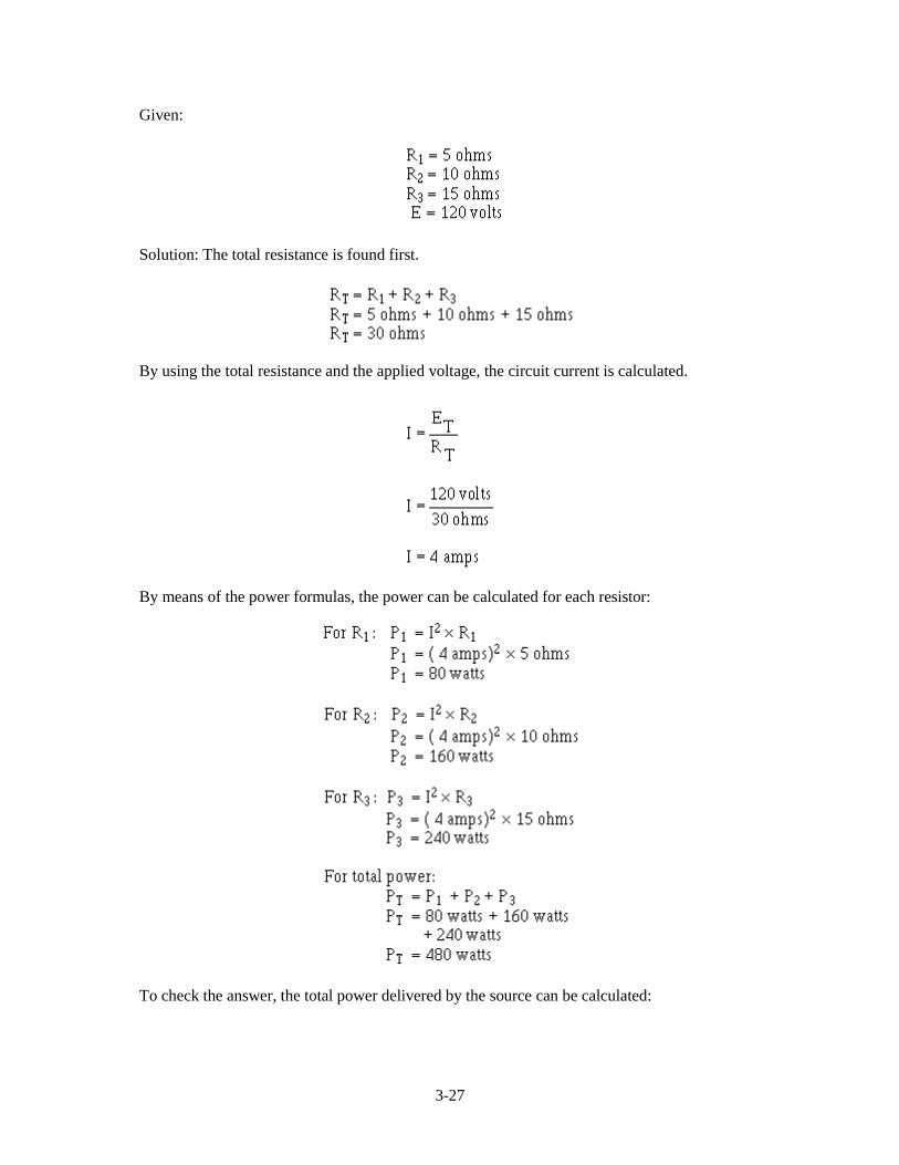
Given:
Solution: The total resistance is found first.
By using the total resistance and the applied voltage, the circuit current is calculated.
By means of the power formulas, the power can be calculated for each resistor:
To check the answer, the total power delivered by the source can be calculated:
3-28
The total power is equal to the sum of the power used by the individual resistors.
SUMMARY OF CHARACTERISTICS
The important factors governing the operation of a series circuit are listed below. These factors havebeen set up as a group of rules so that they may be easily studied. These rules must be completelyunderstood before the study of more advanced circuit theory is undertaken.
Rules for Series DC Circuits
1. The same current flows through each part of a series circuit.
2. The total resistance of a series circuit is equal to the sum of the individual resistances.
3. The total voltage across a series circuit is equal to the sum of the individual voltage drops.
4. The voltage drop across a resistor in a series circuit is proportional to the ohmic value of theresistor.
5. The total power in a series circuit is equal to the sum of the individual powers used by eachcircuit component.
SERIES CIRCUIT ANALYSIS
To establish a procedure for solving series circuits, the following sample problems will be solved.
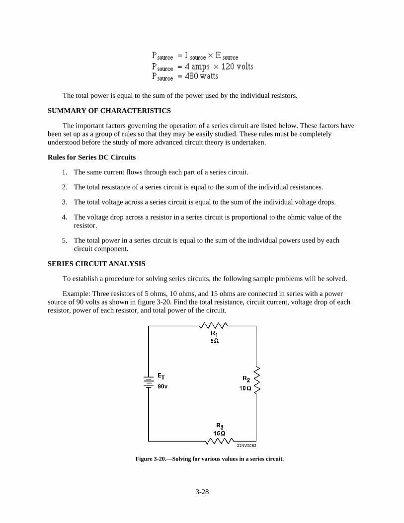
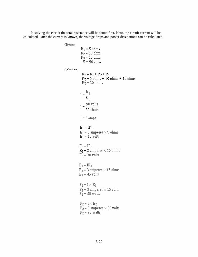
Example: Three resistors of 5 ohms, 10 ohms, and 15 ohms are connected in series with a powersource of 90 volts as shown in figure 3-20. Find the total resistance, circuit current, voltage drop of eachresistor, power of each resistor, and total power of the circuit.
Figure 3-20.—Solving for various values in a series circuit.
3-29
In solving the circuit the total resistance will be found first. Next, the circuit current will becalculated. Once the current is known, the voltage drops and power dissipations can be calculated.
3-30
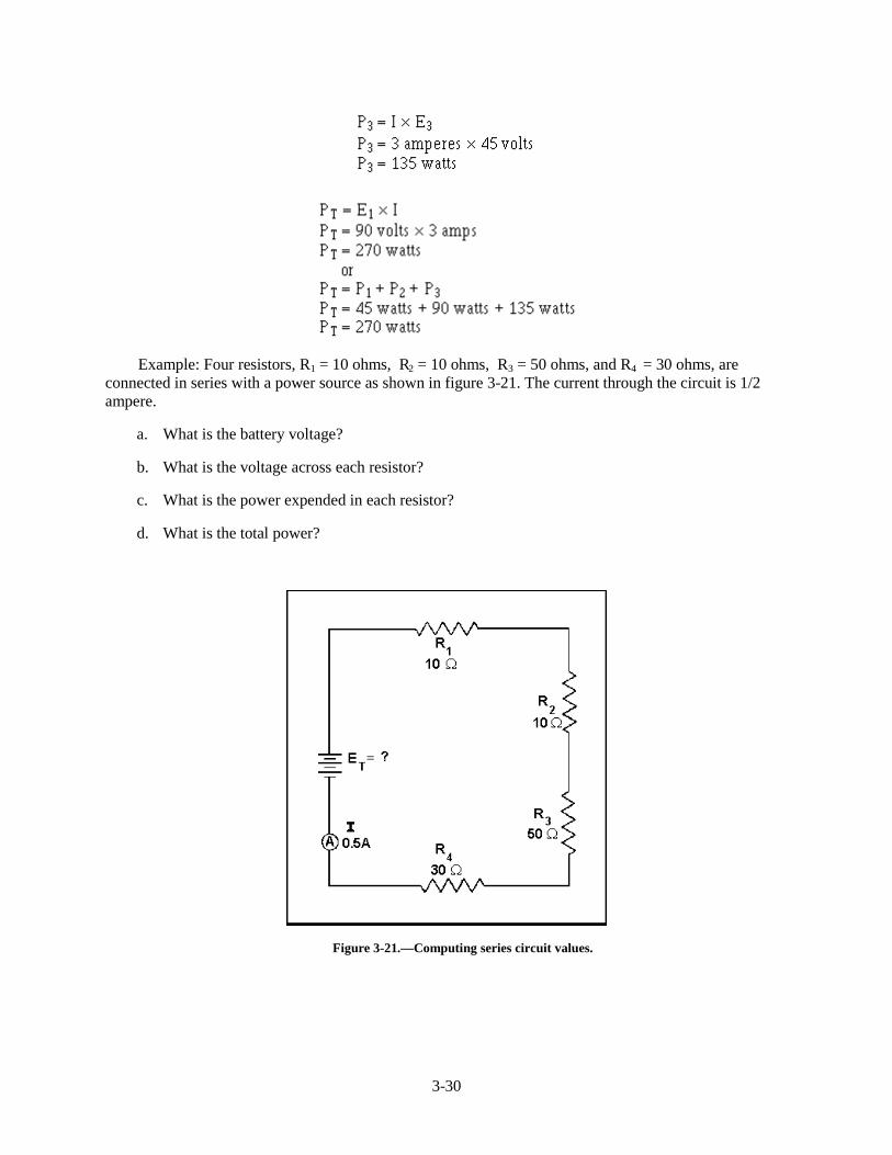
Example: Four resistors, R1 = 10 ohms, R 2 = 10 ohms, R 3 = 50 ohms, and R4 = 30 ohms, areconnected in series with a power source as shown in figure 3-21. The current through the circuit is 1/2ampere.
a. What is the battery voltage?
b. What is the voltage across each resistor?
c. What is the power expended in each resistor?
d. What is the total power?
Figure 3-21.—Computing series circuit values.
3-31
Given:
Solution (a):
Solution (b):
Solution (c):
3-32
Solution (d):
An important fact to keep in mind when applying Ohm’s law to a series circuit is to consider whetherthe values used are component values or total values. When the information available enables the use ofOhm’s law to find total resistance, total voltage, and total current, total values must be inserted into theformula. To find total resistance:
3-33
To find total voltage:
To find total current:
NOTE: IT is equal to I in a series circuit. However, the distinction between IT and I in the formulashould be noted. The reason for this is that future circuits may have several currents, and it will benecessary to differentiate between IT and other currents.
To compute any quantity (E, I, R, or P) associated with a single given resistor, the values used in theformula must be obtained from that particular resistor. For example, to find the value of an unknownresistance, the voltage across and the current through that particular resistor must be used.
To find the value of a resistor:
To find the voltage drop across a resistor:
To find current through a resistor:
Q21. A series circuit consists of two resistors in series. R1 = 25 ohms and R2 = 30 ohms. The circuitcurrent is 6 amps. What is the (a) source voltage, (b) voltage dropped by each resistor, (c) totalpower, and (d) power used by each resistor?
KIRCHHOFF’S VOLTAGE LAW
In 1847, G. R. Kirchhoff extended the use of Ohm’s law by developing a simple concept concerningthe voltages contained in a series circuit loop. Kirchhoff’s voltage law states:
"The algebraic sum of the voltage drops in any closed path in a circuit and the electromotive forcesin that path is equal to zero."
3-34
To state Kirchhoff’s law another way, the voltage drops and voltage sources in a circuit are equal atany given moment in time. If the voltage sources are assumed to have one sign (positive or negative) atthat instant and the voltage drops are assumed to have the opposite sign, the result of adding the voltagesources and voltage drops will be zero.
NOTE: The terms electromotive force and emf are used when explaining Kirchhoff’s law becauseKirchhoff’s law is used in alternating current circuits (covered in Module 2). In applying Kirchhoff’s lawto direct current circuits, the terms electromotive force and emf apply to voltage sources such as batteriesor power supplies.
Through the use of Kirchhoff’s law, circuit problems can be solved which would be difficult, andoften impossible, with knowledge of Ohm’s law alone. When Kirchhoff’s law is properly applied, anequation can be set up for a closed loop and the unknown circuit values can be calculated.
POLARITY OF VOLTAGE
To apply Kirchhoff’s voltage law, the meaning of voltage polarity must be understood.
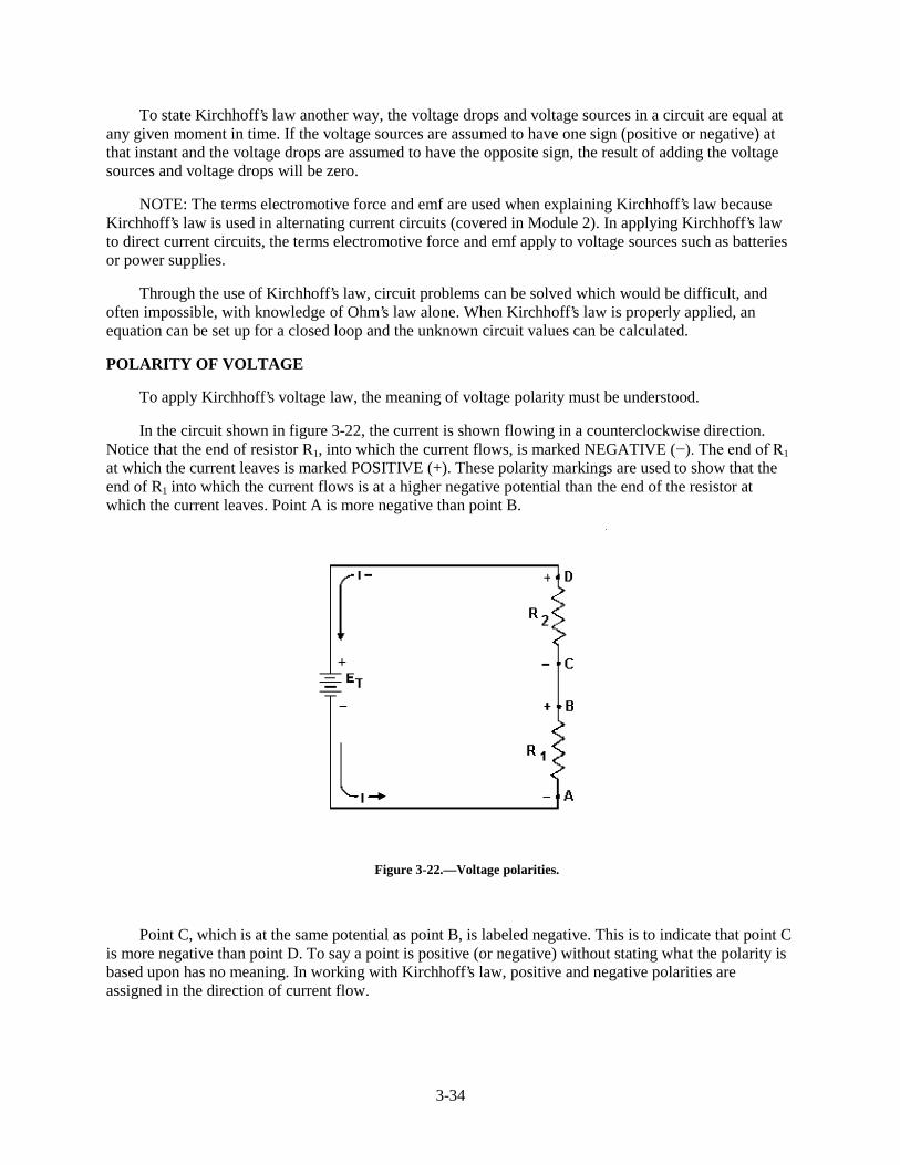
In the circuit shown in figure 3-22, the current is shown flowing in a counterclockwise direction.Notice that the end of resistor R1, into which the current flows, is marked NEGATIVE (��7KH�HQG�RI�51
at which the current leaves is marked POSITIVE (+). These polarity markings are used to show that theend of R1 into which the current flows is at a higher negative potential than the end of the resistor atwhich the current leaves. Point A is more negative than point B.
Figure 3-22.—Voltage polarities.
Point C, which is at the same potential as point B, is labeled negative. This is to indicate that point Cis more negative than point D. To say a point is positive (or negative) without stating what the polarity isbased upon has no meaning. In working with Kirchhoff’s law, positive and negative polarities areassigned in the direction of current flow.
3-35
APPLICATION OF KIRCHHOFF’S VOLTAGE LAW
Kirchhoff’s voltage law can be written as an equation, as shown below:
Ea + Eb + Ec + . . . En = 0
where Ea, Eb, etc., are the voltage drops or emf’s around any closed circuit loop. To set up the equation foran actual circuit, the following procedure is used.
1. Assume a direction of current through the circuit. (The correct direction is desirable but notnecessary.)
2. Using the assumed direction of current, assign polarities to all resistors through which thecurrent flows.
3. Place the correct polarities on any sources included in the circuit.
4. Starting at any point in the circuit, trace around the circuit, writing down the amount and polarityof the voltage across each component in succession. The polarity used is the sign AFTER theassumed current has passed through the component. Stop when the point at which the trace wasstarted is reached.
5. Place these voltages, with their polarities, into the equation and solve for the desired quantity.
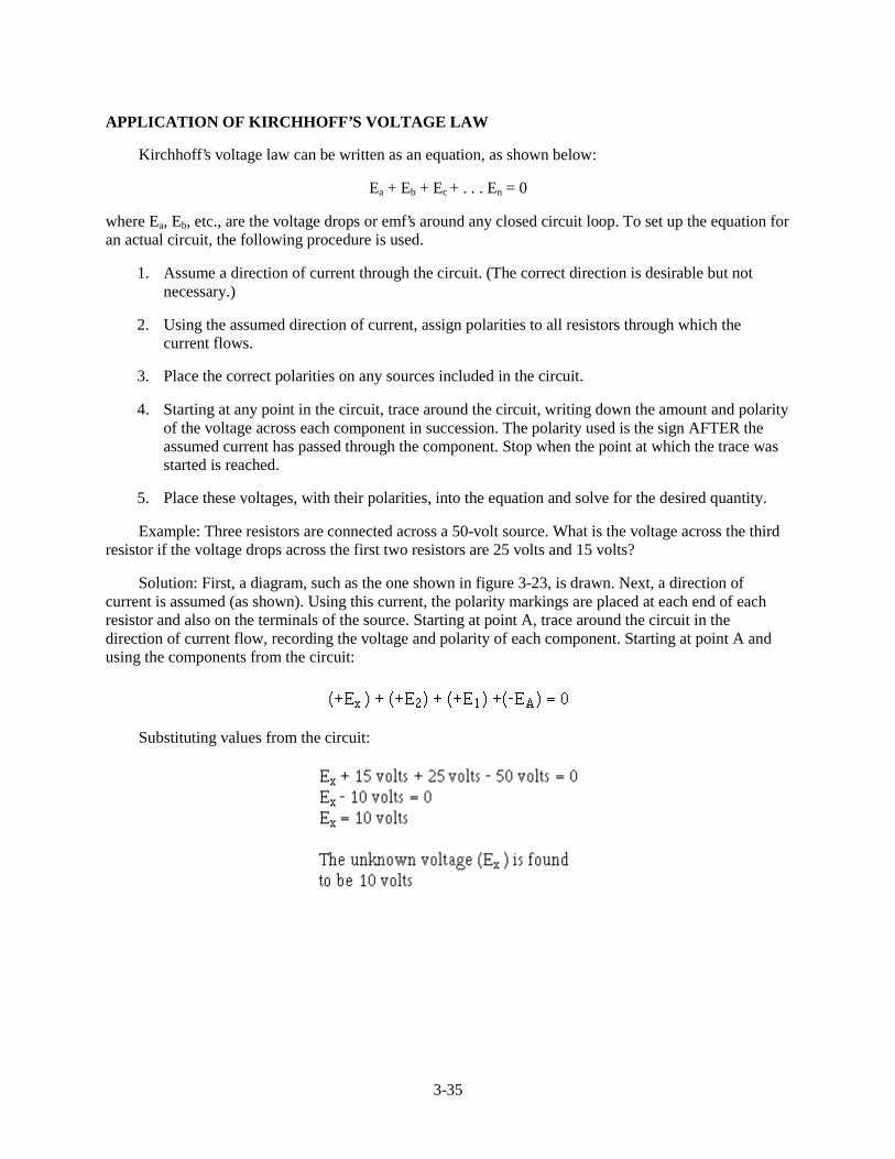
Example: Three resistors are connected across a 50-volt source. What is the voltage across the thirdresistor if the voltage drops across the first two resistors are 25 volts and 15 volts?
Solution: First, a diagram, such as the one shown in figure 3-23, is drawn. Next, a direction ofcurrent is assumed (as shown). Using this current, the polarity markings are placed at each end of eachresistor and also on the terminals of the source. Starting at point A, trace around the circuit in thedirection of current flow, recording the voltage and polarity of each component. Starting at point A andusing the components from the circuit:
Substituting values from the circuit:
3-36
Figure 3-23.—Determining unknown voltage in a series circuit.
Using the same idea as above, you can solve a problem in which the current is the unknown quantity.
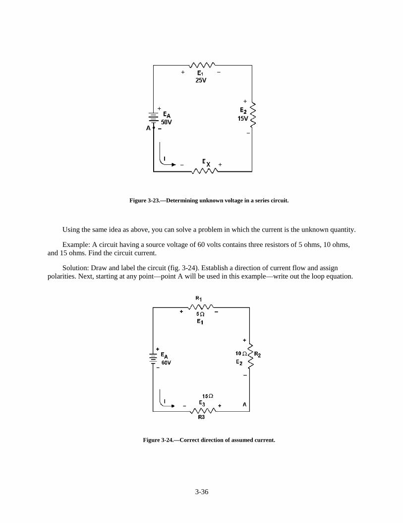
Example: A circuit having a source voltage of 60 volts contains three resistors of 5 ohms, 10 ohms,and 15 ohms. Find the circuit current.
Solution: Draw and label the circuit (fig. 3-24). Establish a direction of current flow and assignpolarities. Next, starting at any point—point A will be used in this example—write out the loop equation.
Figure 3-24.—Correct direction of assumed current.
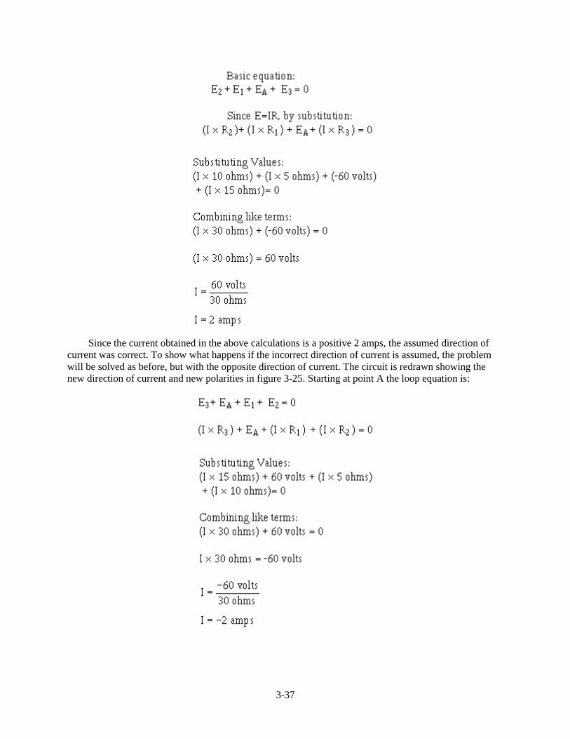
3-37
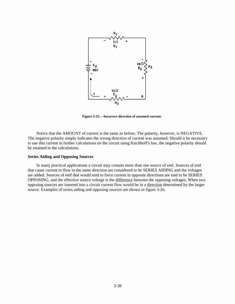
Since the current obtained in the above calculations is a positive 2 amps, the assumed direction ofcurrent was correct. To show what happens if the incorrect direction of current is assumed, the problemwill be solved as before, but with the opposite direction of current. The circuit is redrawn showing thenew direction of current and new polarities in figure 3-25. Starting at point A the loop equation is:
3-38
Figure 3-25.—Incorrect direction of assumed current.
Notice that the AMOUNT of current is the same as before. The polarity, however, is NEGATIVE.The negative polarity simply indicates the wrong direction of current was assumed. Should it be necessaryto use this current in further calculations on the circuit using Kirchhoff’s law, the negative polarity shouldbe retained in the calculations.
Series Aiding and Opposing Sources
In many practical applications a circuit may contain more than one source of emf. Sources of emfthat cause current to flow in the same direction are considered to be SERIES AIDING and the voltagesare added. Sources of emf that would tend to force current in opposite directions are said to be SERIESOPPOSING, and the effective source voltage is the difference between the opposing voltages. When twoopposing sources are inserted into a circuit current flow would be in a direction determined by the largersource. Examples of series aiding and opposing sources are shown in figure 3-26.

3-39
Figure 3-26.—Aiding and opposing sources.
A simple solution may be obtained for a multiple-source circuit through the use of Kirchhoff’svoltage law. In applying this method, the same procedure is used for the multiple-source circuit as wasused above for the single-source circuit. This is demonstrated by the following example.
Example: Using Kirchhoff’s voltage equation, find the amount of current in the circuit shown infig 3-27.
Figure 3-27.-Solving for circuit current using Kirchhoff's voltage equation.
3-40
Solution: As before, a direction of current flow is assumed and polarity signs are placed on thedrawing. The loop equation will be started at point A.
E2 + ER1 + E 1 + E3 + ER2 = 0
Q22. When using Kirchhoff’s voltage law, how are voltage polarities assigned to the voltage dropsacross resistors?
Q23. Refer to figure 3-27, if R1 was changed to a 40-ohm resistor, what would be the value of circuitcurrent (I T)?
Q24. Refer to figure 3-27. What is the effective source voltage of the circuit using the 40-ohm resistor?
CIRCUIT TERMS AND CHARACTERISTICS
Before you learn about the types of circuits other than the series circuit, you should become familiarwith some of the terms and characteristics used in electrical circuits. These terms and characteristics willbe used throughout your study of electricity and electronics.
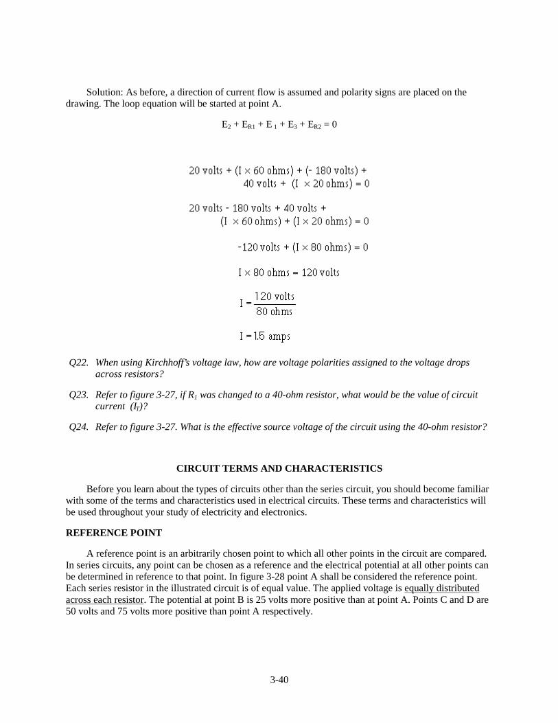
REFERENCE POINT
A reference point is an arbitrarily chosen point to which all other points in the circuit are compared.In series circuits, any point can be chosen as a reference and the electrical potential at all other points canbe determined in reference to that point. In figure 3-28 point A shall be considered the reference point.Each series resistor in the illustrated circuit is of equal value. The applied voltage is equally distributedacross each resistor. The potential at point B is 25 volts more positive than at point A. Points C and D are50 volts and 75 volts more positive than point A respectively.
3-41
Figure 3-28.—Reference points in a series circuit.
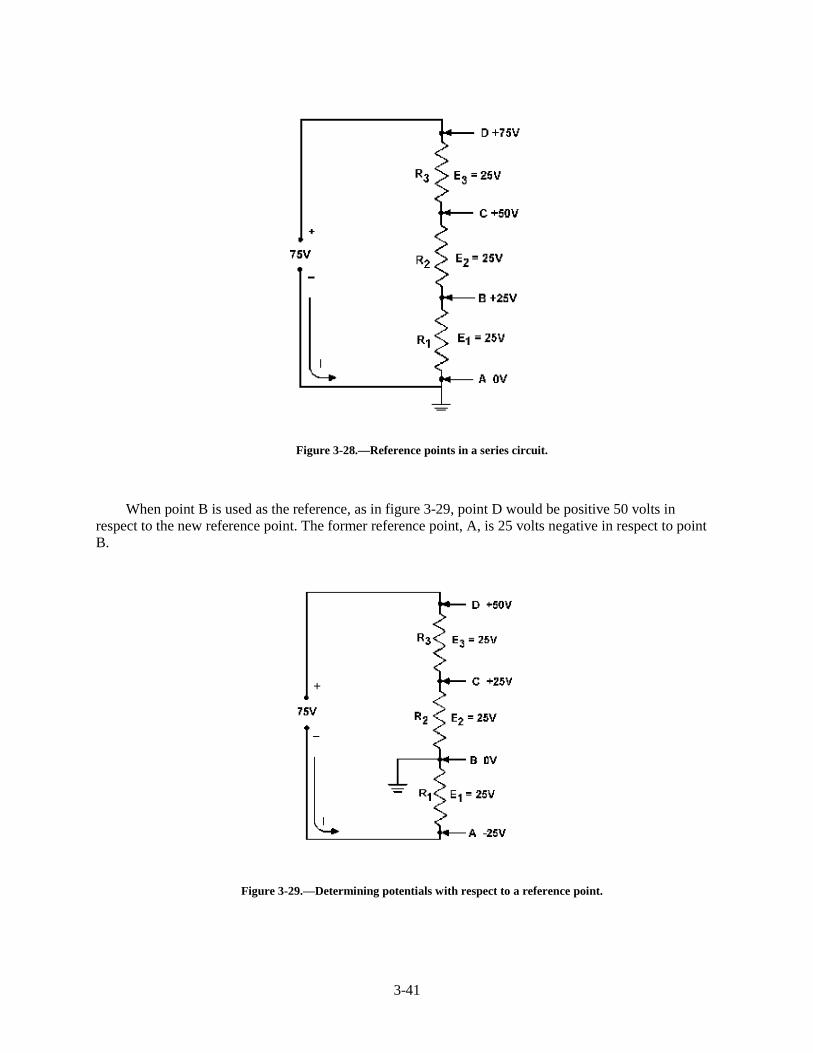
When point B is used as the reference, as in figure 3-29, point D would be positive 50 volts inrespect to the new reference point. The former reference point, A, is 25 volts negative in respect to pointB.
Figure 3-29.—Determining potentials with respect to a reference point.
3-42
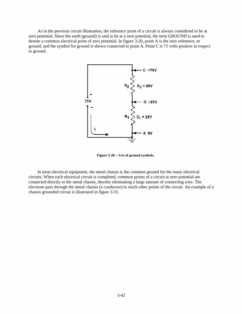
As in the previous circuit illustration, the reference point of a circuit is always considered to be atzero potential. Since the earth (ground) is said to be at a zero potential, the term GROUND is used todenote a common electrical point of zero potential. In figure 3-30, point A is the zero reference, orground, and the symbol for ground is shown connected to point A. Point C is 75 volts positive in respectto ground.
Figure 3-30.—Use of ground symbols.
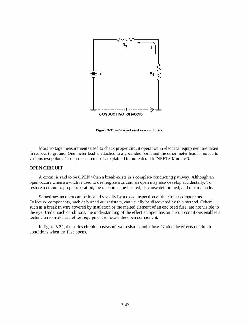
In most electrical equipment, the metal chassis is the common ground for the many electricalcircuits. When each electrical circuit is completed, common points of a circuit at zero potential areconnected directly to the metal chassis, thereby eliminating a large amount of connecting wire. Theelectrons pass through the metal chassis (a conductor) to reach other points of the circuit. An example of achassis grounded circuit is illustrated in figure 3-31.
3-43
Figure 3-31.—Ground used as a conductor.
Most voltage measurements used to check proper circuit operation in electrical equipment are takenin respect to ground. One meter lead is attached to a grounded point and the other meter lead is moved tovarious test points. Circuit measurement is explained in more detail in NEETS Module 3.
OPEN CIRCUIT
A circuit is said to be OPEN when a break exists in a complete conducting pathway. Although anopen occurs when a switch is used to deenergize a circuit, an open may also develop accidentally. Torestore a circuit to proper operation, the open must be located, its cause determined, and repairs made.
Sometimes an open can be located visually by a close inspection of the circuit components.Defective components, such as burned out resistors, can usually be discovered by this method. Others,such as a break in wire covered by insulation or the melted element of an enclosed fuse, are not visible tothe eye. Under such conditions, the understanding of the effect an open has on circuit conditions enables atechnician to make use of test equipment to locate the open component.
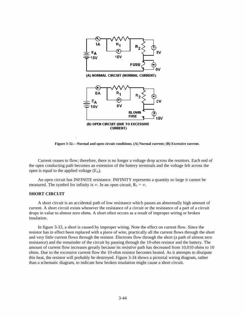
In figure 3-32, the series circuit consists of two resistors and a fuse. Notice the effects on circuitconditions when the fuse opens.
3-44
Figure 3-32.—Normal and open circuit conditions. (A) Normal current; (B) Excessive current.
Current ceases to flow; therefore, there is no longer a voltage drop across the resistors. Each end ofthe open conducting path becomes an extension of the battery terminals and the voltage felt across theopen is equal to the applied voltage (EA).
An open circuit has INFINITE resistance. INFINITY represents a quantity so large it cannot bemeasured. The symbol for infinity is ���,Q�DQ�RSHQ�FLUFXLW��5T = ��
SHORT CIRCUIT
A short circuit is an accidental path of low resistance which passes an abnormally high amount ofcurrent. A short circuit exists whenever the resistance of a circuit or the resistance of a part of a circuitdrops in value to almost zero ohms. A short often occurs as a result of improper wiring or brokeninsulation.
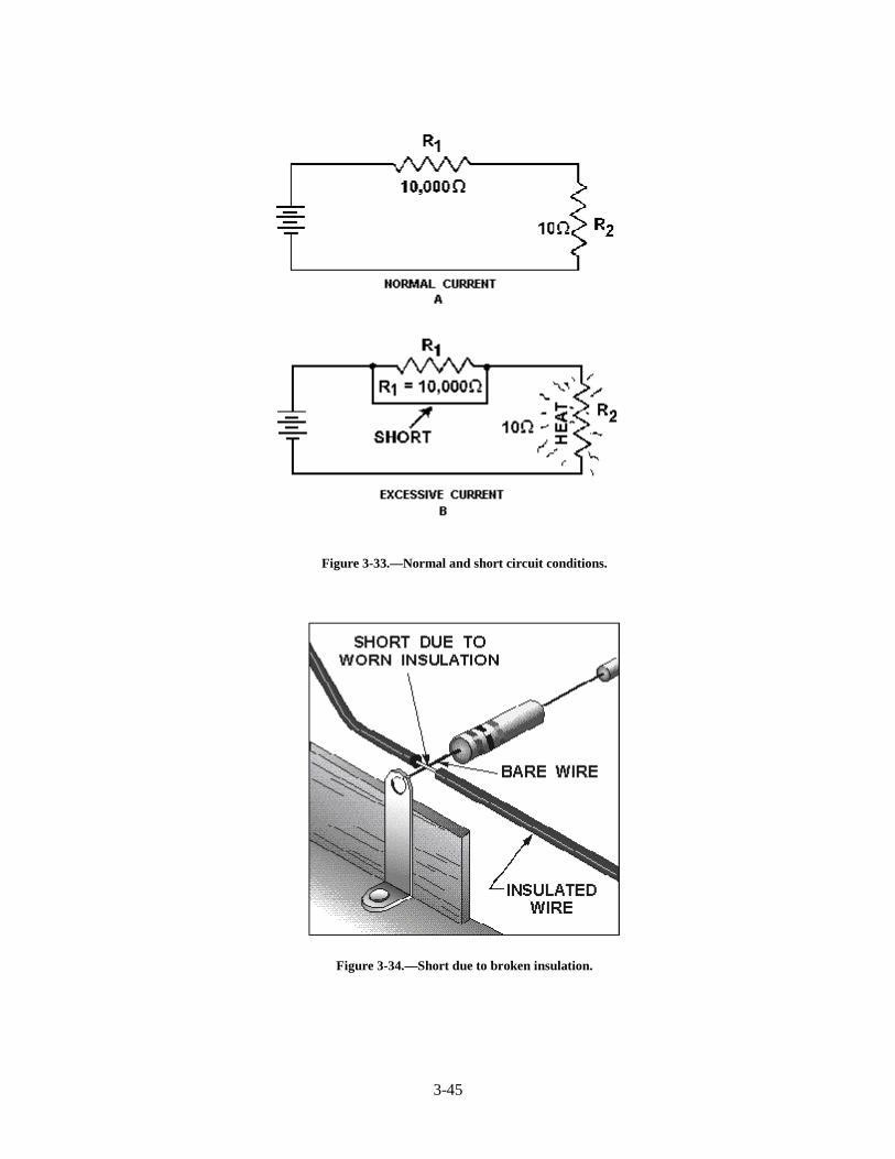
In figure 3-33, a short is caused by improper wiring. Note the effect on current flow. Since theresistor has in effect been replaced with a piece of wire, practically all the current flows through the shortand very little current flows through the resistor. Electrons flow through the short (a path of almost zeroresistance) and the remainder of the circuit by passing through the 10-ohm resistor and the battery. Theamount of current flow increases greatly because its resistive path has decreased from 10,010 ohms to 10ohms. Due to the excessive current flow the 10-ohm resistor becomes heated. As it attempts to dissipatethis heat, the resistor will probably be destroyed. Figure 3-34 shows a pictorial wiring diagram, ratherthan a schematic diagram, to indicate how broken insulation might cause a short circuit.
3-45
Figure 3-33.—Normal and short circuit conditions.
Figure 3-34.—Short due to broken insulation.
3-46
SOURCE RESISTANCE
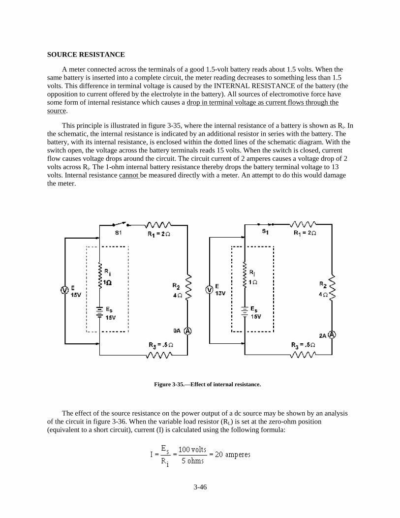
A meter connected across the terminals of a good 1.5-volt battery reads about 1.5 volts. When thesame battery is inserted into a complete circuit, the meter reading decreases to something less than 1.5volts. This difference in terminal voltage is caused by the INTERNAL RESISTANCE of the battery (theopposition to current offered by the electrolyte in the battery). All sources of electromotive force havesome form of internal resistance which causes a drop in terminal voltage as current flows through thesource.
This principle is illustrated in figure 3-35, where the internal resistance of a battery is shown as Ri. Inthe schematic, the internal resistance is indicated by an additional resistor in series with the battery. Thebattery, with its internal resistance, is enclosed within the dotted lines of the schematic diagram. With theswitch open, the voltage across the battery terminals reads 15 volts. When the switch is closed, currentflow causes voltage drops around the circuit. The circuit current of 2 amperes causes a voltage drop of 2volts across Ri. The 1-ohm internal battery resistance thereby drops the battery terminal voltage to 13volts. Internal resistance cannot be measured directly with a meter. An attempt to do this would damagethe meter.
Figure 3-35.—Effect of internal resistance.
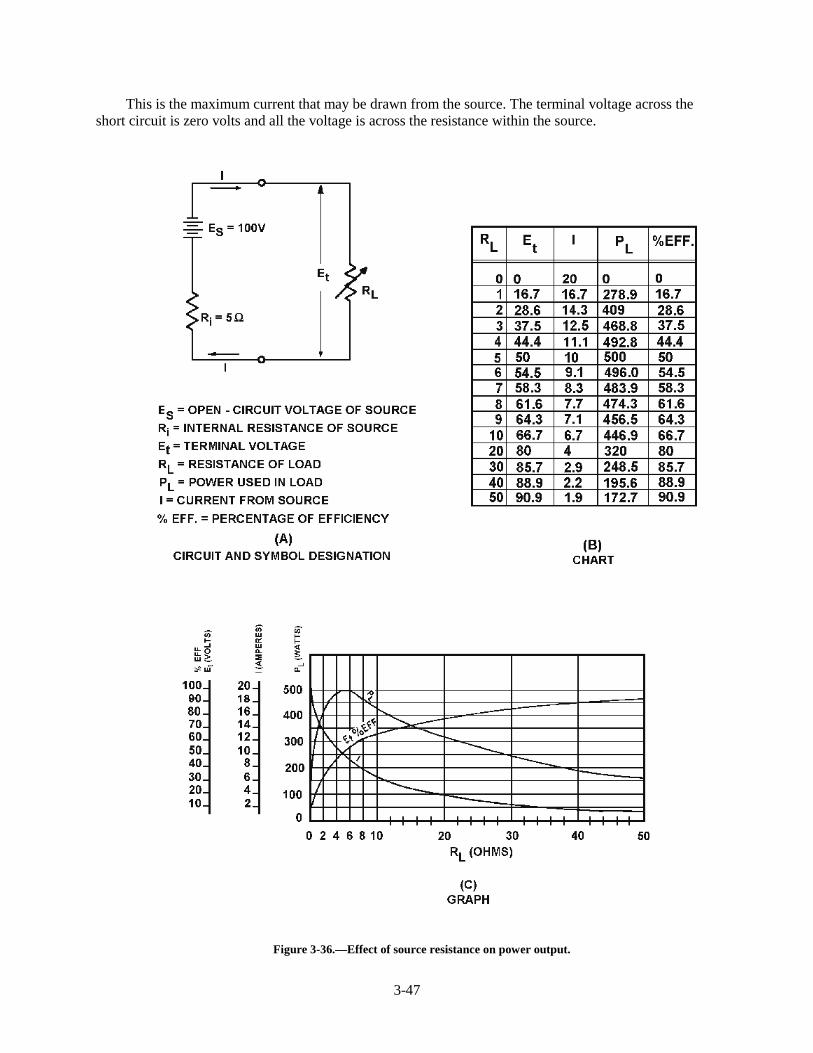
The effect of the source resistance on the power output of a dc source may be shown by an analysisof the circuit in figure 3-36. When the variable load resistor (RL) is set at the zero-ohm position(equivalent to a short circuit), current (I) is calculated using the following formula:
3-47
This is the maximum current that may be drawn from the source. The terminal voltage across theshort circuit is zero volts and all the voltage is across the resistance within the source.
Figure 3-36.—Effect of source resistance on power output.
3-48
If the load resistance (RL) were increased (the internal resistance remaining the same), the currentdrawn from the source would decrease. Consequently, the voltage drop across the internal resistancewould decrease. At the same time, the terminal voltage applied across the load would increase andapproach a maximum as the current approaches zero amps.
POWER TRANSFER AND EFFICIENCY
Maximum power is transferred from the source to the load when the resistance of the load is equal tothe internal resistance of the source. This theory is illustrated in the table and the graph of figure 3-36.When the load resistance is 5 ohms, matching the source resistance, the maximum power of 500 watts isdeveloped in the load.
The efficiency of power transfer (ratio of output power to input power) from the source to the loadincreases as the load resistance is increased. The efficiency approaches 100 percent as the load resistanceapproaches a relatively large value compared with that of the source, since less power is lost in the source.The efficiency of power transfer is only 50 percent at the maximum power transfer point (when the loadresistance equals the internal resistance of the source). The efficiency of power transfer approaches zeroefficiency when the load resistance is relatively small compared with the internal resistance of the source.This is also shown on the chart of figure 3-36.
The problem of a desire for both high efficiency and maximum power transfer is resolved by acompromise between maximum power transfer and high efficiency. Where the amounts of powerinvolved are large and the efficiency is important, the load resistance is made large relative to the sourceresistance so that the losses are kept small. In this case, the efficiency is high. Where the problem ofmatching a source to a load is important, as in communications circuits, a strong signal may be moreimportant than a high percentage of efficiency. In such cases, the efficiency of power transfer should beonly about 50 percent; however, the power transfer would be the maximum which the source is capable ofsupplying.
You should now understand the basic concepts of series circuits. The principles which have beenpresented are of lasting importance. Once equipped with a firm understanding of series circuits, you holdthe key to an understanding of the parallel circuits to be presented next.
Q25. A circuit has a source voltage of 100 volts and two 50-ohm resistors connected in series. If thereference point for this circuit is placed between the two resistors, what would be the voltage atthe reference point?
Q26. If the reference point in question 25 were connected to ground, what would be the voltage level ofthe reference point?
Q27. What is an open circuit?
Q28. What is a short circuit?
Q29. Why will a meter indicate more voltage at the battery terminal when the battery is out of a circuitthan when the battery is in a circuit?
Q30. What condition gives maximum power transfer from the source to the load?
Q31. What is the efficiency of power transfer in question 30?
Q32. A circuit has a source voltage of 25 volts. The source resistance is 1 ohm and the load resistanceis 49 ohms. What is the efficiency of power transfer?
3-49
PARALLEL DC CIRCUITS
The discussion of electrical circuits presented up to this point has been concerned with series circuitsin which there is only one path for current. There is another basic type of circuit known as thePARALLEL CIRCUIT with which you must become familiar. Where the series circuit has only one pathfor current, the parallel circuit has more than one path for current.
Ohm’s law and Kirchhoff’s law apply to all electrical circuits, but the characteristics of a parallel dccircuit are different than those of a series dc circuit.
PARALLEL CIRCUIT CHARACTERISTICS
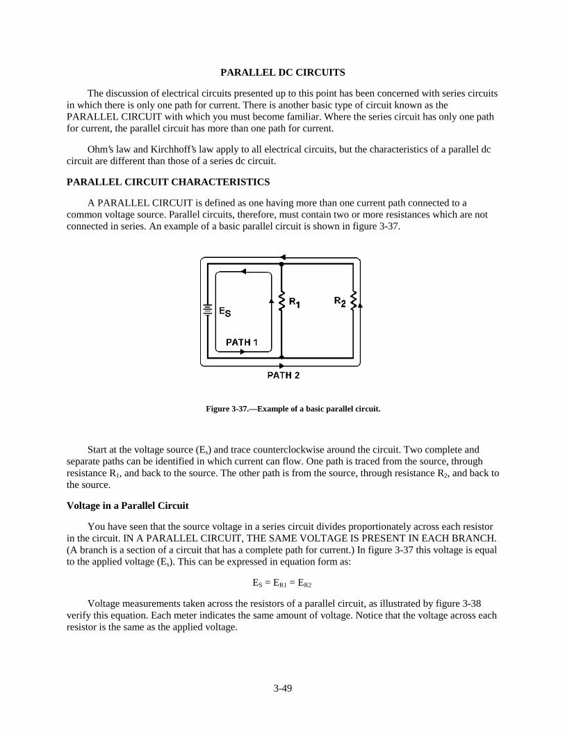
A PARALLEL CIRCUIT is defined as one having more than one current path connected to acommon voltage source. Parallel circuits, therefore, must contain two or more resistances which are notconnected in series. An example of a basic parallel circuit is shown in figure 3-37.
Figure 3-37.—Example of a basic parallel circuit.
Start at the voltage source (Es) and trace counterclockwise around the circuit. Two complete andseparate paths can be identified in which current can flow. One path is traced from the source, throughresistance R1, and back to the source. The other path is from the source, through resistance R2, and back tothe source.
Voltage in a Parallel Circuit
You have seen that the source voltage in a series circuit divides proportionately across each resistorin the circuit. IN A PARALLEL CIRCUIT, THE SAME VOLTAGE IS PRESENT IN EACH BRANCH.(A branch is a section of a circuit that has a complete path for current.) In figure 3-37 this voltage is equalto the applied voltage (Es). This can be expressed in equation form as:
ES = ER1 = ER2
Voltage measurements taken across the resistors of a parallel circuit, as illustrated by figure 3-38verify this equation. Each meter indicates the same amount of voltage. Notice that the voltage across eachresistor is the same as the applied voltage.
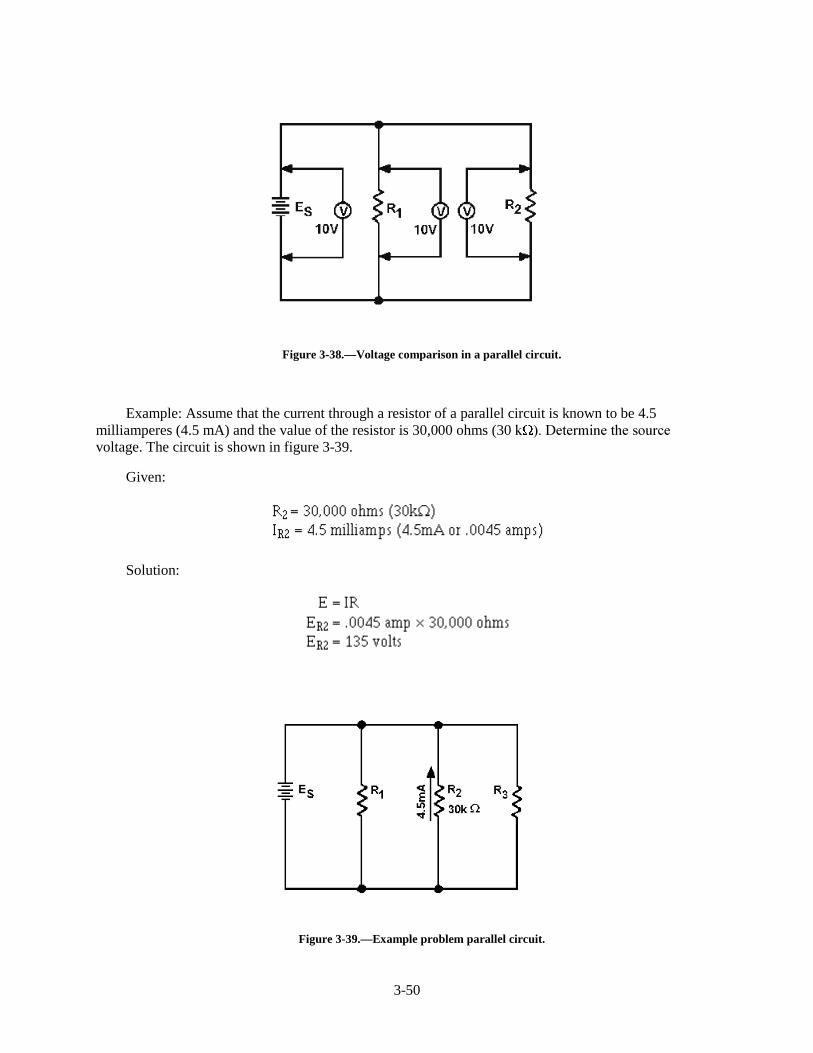
3-50
Figure 3-38.—Voltage comparison in a parallel circuit.
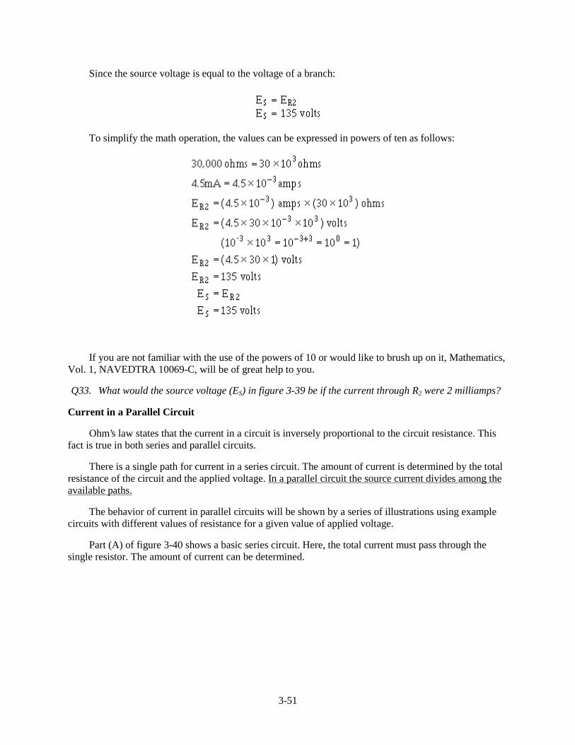
Example: Assume that the current through a resistor of a parallel circuit is known to be 4.5milliamperes (4.5 mA) and the value of the resistor is 30,000 ohms (30 N ���'HWHUPLQH�WKH�VRXUFHvoltage. The circuit is shown in figure 3-39.
Given:
Solution:
Figure 3-39.—Example problem parallel circuit.
3-51
Since the source voltage is equal to the voltage of a branch:
To simplify the math operation, the values can be expressed in powers of ten as follows:
If you are not familiar with the use of the powers of 10 or would like to brush up on it, Mathematics,Vol. 1, NAVEDTRA 10069-C, will be of great help to you.
Q33. What would the source voltage (ES) in figure 3-39 be if the current through R2 were 2 milliamps?
Current in a Parallel Circuit
Ohm’s law states that the current in a circuit is inversely proportional to the circuit resistance. Thisfact is true in both series and parallel circuits.
There is a single path for current in a series circuit. The amount of current is determined by the totalresistance of the circuit and the applied voltage. In a parallel circuit the source current divides among theavailable paths.
The behavior of current in parallel circuits will be shown by a series of illustrations using examplecircuits with different values of resistance for a given value of applied voltage.
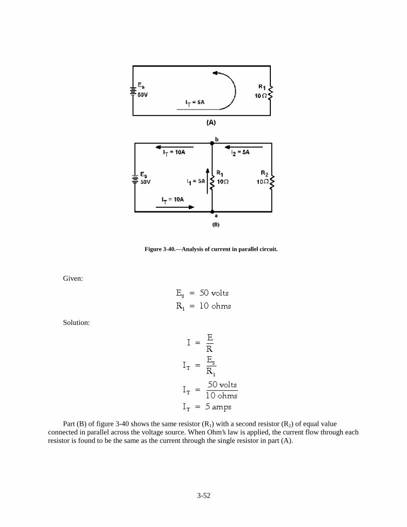
Part (A) of figure 3-40 shows a basic series circuit. Here, the total current must pass through thesingle resistor. The amount of current can be determined.
3-52
Figure 3-40.—Analysis of current in parallel circuit.
Given:
Solution:
Part (B) of figure 3-40 shows the same resistor (R1) with a second resistor (R2) of equal valueconnected in parallel across the voltage source. When Ohm’s law is applied, the current flow through eachresistor is found to be the same as the current through the single resistor in part (A).
3-53
Given:
Solution:
It is apparent that if there is 5 amperes of current through each of the two resistors, there must be aTOTAL CURRENT of 10 amperes drawn from the source.
The total current of 10 amperes, as illustrated in figure 3-40(B), leaves the negative terminal of thebattery and flows to point a. Since point a is a connecting point for the two resistors, it is called aJUNCTION. At junction a, the total current divides into two currents of 5 amperes each. These twocurrents flow through their respective resistors and rejoin at junction b. The total current then flows fromjunction b back to the positive terminal of the source. The source supplies a total current of 10 amperesand each of the two equal resistors carries one-half the total current.
Each individual current path in the circuit of figure 3-40(B) is referred to as a BRANCH. Eachbranch carries a current that is a portion of the total current. Two or more branches form a NETWORK.
From the previous explanation, the characteristics of current in a parallel circuit can be expressed interms of the following general equation:
IT = I1 + I 2 + . . . In
3-54
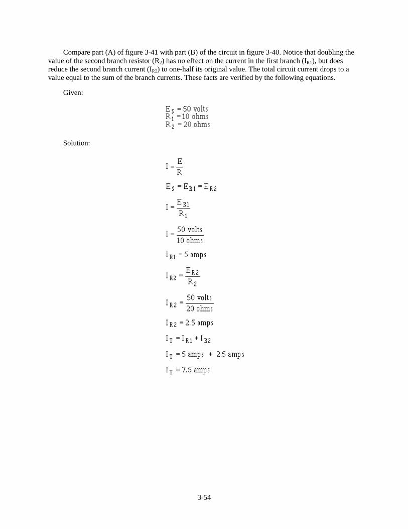
Compare part (A) of figure 3-41 with part (B) of the circuit in figure 3-40. Notice that doubling thevalue of the second branch resistor (R2) has no effect on the current in the first branch (IR1), but doesreduce the second branch current (IR2) to one-half its original value. The total circuit current drops to avalue equal to the sum of the branch currents. These facts are verified by the following equations.
Given:
Solution:
3-55
Figure 3-41.—Current behavior in parallel circuits.
The amount of current flow in the branch circuits and the total current in the circuit shown in figure3-41(B) are determined by the following computations.
Given:
3-56
Solution:
Notice that the sum of the ohmic values in each circuit shown in figure 3-41 is equal (30 ohms), andthat the applied voltage is the same (50 volts). However, the total current in 3-41(B) (15 amps) is twicethe amount in 3-41(A) (7.5 amps). It is apparent, therefore, that the manner in which resistors areconnected in a circuit, as well as their actual ohmic values, affect the total current.
The division of current in a parallel network follows a definite pattern. This pattern is described byKIRCHHOFF’S CURRENT LAW which states:
3-57
"The algebraic sum of the currents entering and leaving any junction of conductors is equal to zero."
This law can be stated mathematically as:
Ia + lb + . . . I n + 0
where: Ia, Ib, etc., are the currents entering and leaving the junction. Currents ENTERING thejunction are considered to be POSITIVE and currents LEAVING the junction are considered to beNEGATIVE. When solving a problem using Kirchhoff’s current law, the currents must be placed into theequation WITH THE PROPER POLARITY SIGNS ATTACHED.
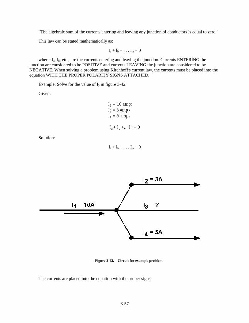
Example: Solve for the value of I3 in figure 3-42.
Given:
Solution:
Ia + lb + . . . I a + 0
Figure 3-42.—Circuit for example problem.
The currents are placed into the equation with the proper signs.
3-58
I3 has a value of 2 amperes, and the negative sign shows it to be a current LEAVING the junction.
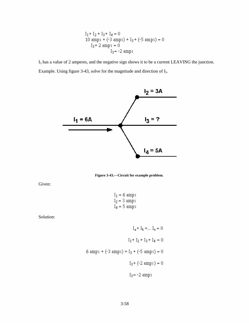
Example. Using figure 3-43, solve for the magnitude and direction of I3.
Figure 3-43.—Circuit for example problem.
Given:
Solution:
3-59
I3 is 2 amperes and its positive sign shows it to be a current entering the junction.
Q34. There is a relationship between total current and current through the individual components in acircuit. What is this relationship in a series circuit and a parallel circuit?
Q35. In applying Kirchhoff’s current law, what does the polarity of the current indicate?
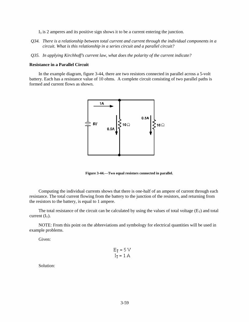
Resistance in a Parallel Circuit
In the example diagram, figure 3-44, there are two resistors connected in parallel across a 5-voltbattery. Each has a resistance value of 10 ohms. A complete circuit consisting of two parallel paths isformed and current flows as shown.
Figure 3-44.—Two equal resistors connected in parallel.
Computing the individual currents shows that there is one-half of an ampere of current through eachresistance. The total current flowing from the battery to the junction of the resistors, and returning fromthe resistors to the battery, is equal to 1 ampere.
The total resistance of the circuit can be calculated by using the values of total voltage (ET) and totalcurrent (IT).
NOTE: From this point on the abbreviations and symbology for electrical quantities will be used inexample problems.
Given:
Solution:
3-60
This computation shows the total resistance to be 5 ohms; one-half the value of either of the tworesistors.
Since the total resistance of a parallel circuit is smaller than any of the individual resistors, totalresistance of a parallel circuit is not the sum of the individual resistor values as was the case in a seriescircuit. The total resistance of resistors in parallel is also referred to as EQUIVALENT RESISTANCE(Req). The terms total resistance and equivalent resistance are used interchangeably.
There are several methods used to determine the equivalent resistance of parallel circuits. The bestmethod for a given circuit depends on the number and value of the resistors. For the circuit describedabove, where all resistors have the same value, the following simple equation is used:
This equation is valid for any number of parallel resistors of EQUAL VALUE.
Example: Four 40-ohm resistors are connected in parallel. What is their equivalent resistance?
Given:
Solution:
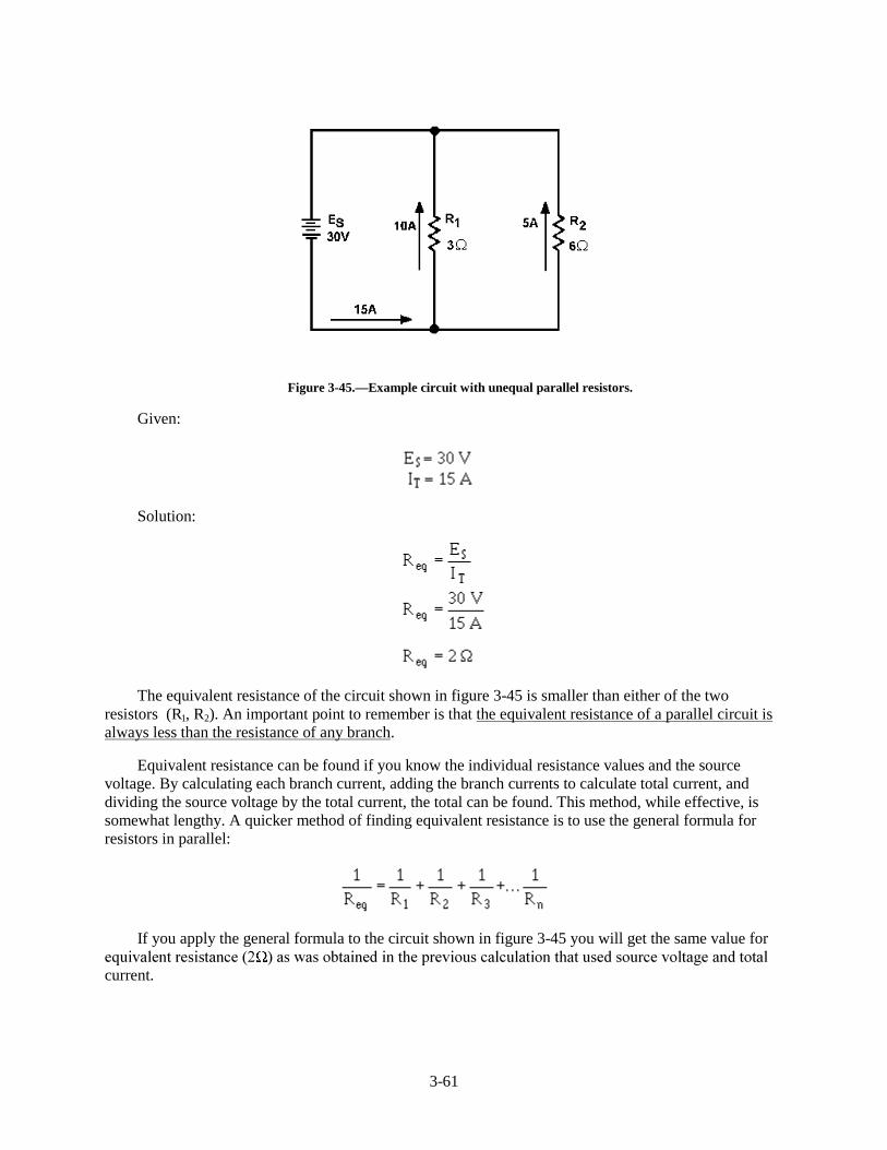
Figure 3-45 shows two resistors of unequal value in parallel. Since the total current is shown, theequivalent resistance can be calculated.
3-61
Figure 3-45.—Example circuit with unequal parallel resistors.
Given:
Solution:
The equivalent resistance of the circuit shown in figure 3-45 is smaller than either of the tworesistors (R 1, R2). An important point to remember is that the equivalent resistance of a parallel circuit isalways less than the resistance of any branch.
Equivalent resistance can be found if you know the individual resistance values and the sourcevoltage. By calculating each branch current, adding the branch currents to calculate total current, anddividing the source voltage by the total current, the total can be found. This method, while effective, issomewhat lengthy. A quicker method of finding equivalent resistance is to use the general formula forresistors in parallel:
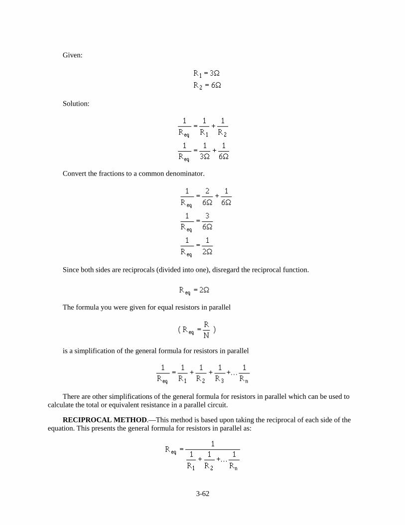
If you apply the general formula to the circuit shown in figure 3-45 you will get the same value forHTXLYDOHQW�UHVLVWDQFH��� ��DV�ZDV�REWDLQHG�LQ�WKH�SUHYLRXV�FDOFXODWLRQ�WKDW�XVHG�VRXUFH�YROWDJH�DQG�WRWDOcurrent.
3-62
Given:
Solution:
Convert the fractions to a common denominator.
Since both sides are reciprocals (divided into one), disregard the reciprocal function.
The formula you were given for equal resistors in parallel
is a simplification of the general formula for resistors in parallel
There are other simplifications of the general formula for resistors in parallel which can be used tocalculate the total or equivalent resistance in a parallel circuit.
RECIPROCAL METHOD.—This method is based upon taking the reciprocal of each side of theequation. This presents the general formula for resistors in parallel as:
3-63
This formula is used to solve for the equivalent resistance of a number of unequal parallel resistors.You must find the lowest common denominator in solving these problems. If you are a little hazy onfinding the lowest common denominator, brush up on it in Mathematics Volume 1, NAVEDTRA 10069(Series).
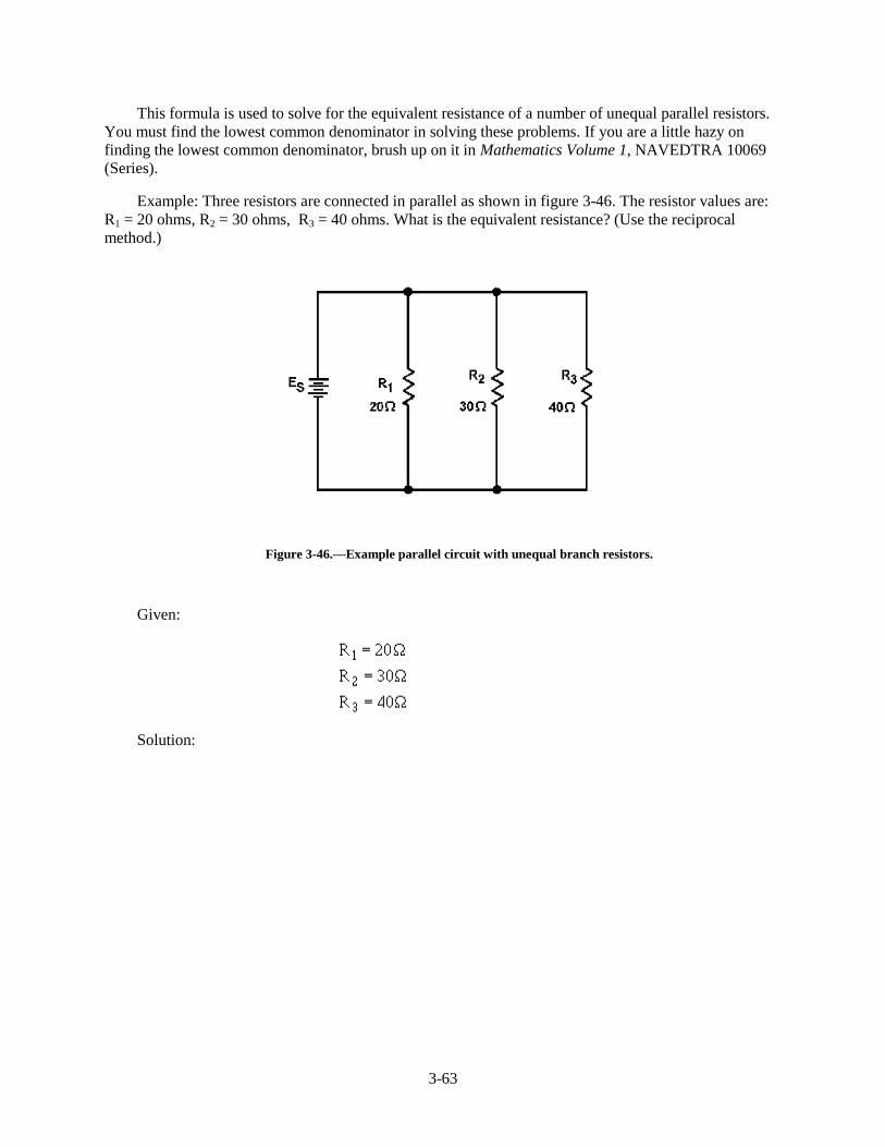
Example: Three resistors are connected in parallel as shown in figure 3-46. The resistor values are:R1 = 20 ohms, R2 = 30 ohms, R 3 = 40 ohms. What is the equivalent resistance? (Use the reciprocalmethod.)
Figure 3-46.—Example parallel circuit with unequal branch resistors.
Given:
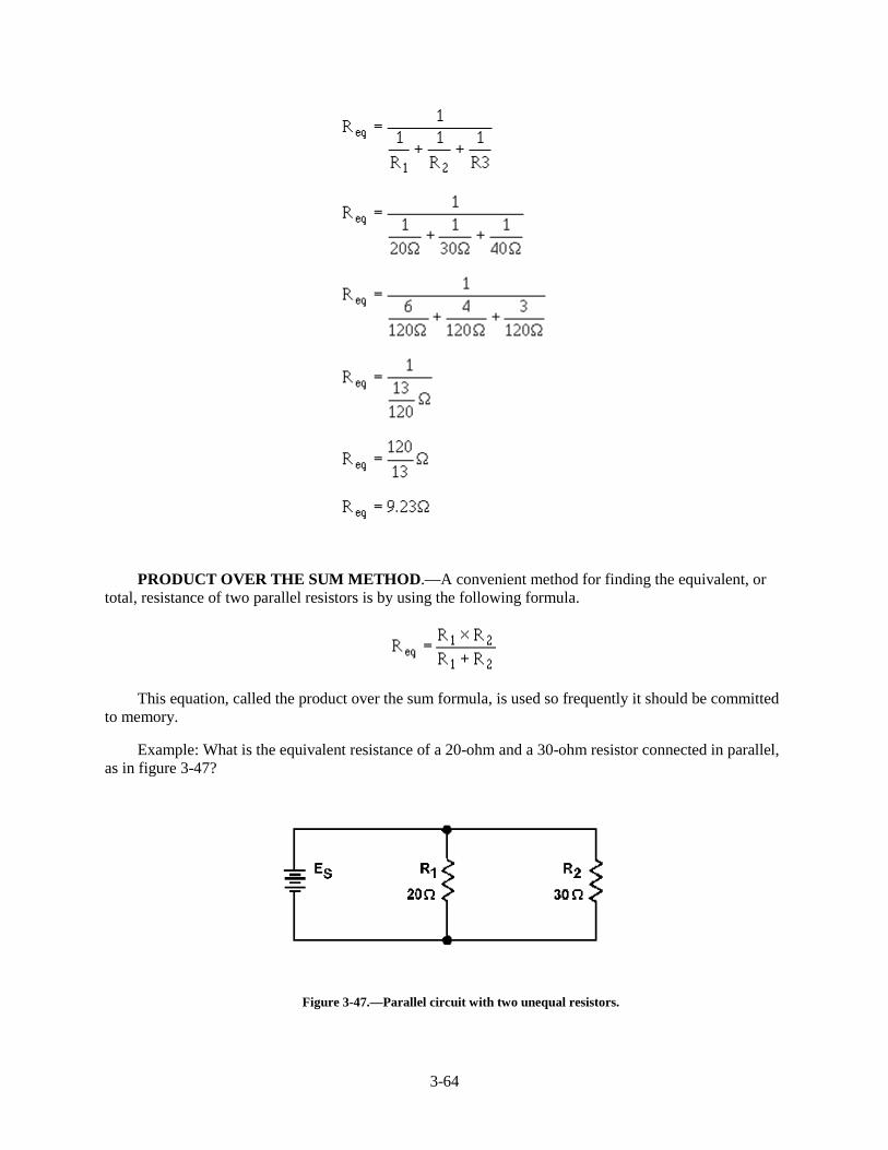
Solution:
3-64
PRODUCT OVER THE SUM METHOD.—A convenient method for finding the equivalent, ortotal, resistance of two parallel resistors is by using the following formula.
This equation, called the product over the sum formula, is used so frequently it should be committedto memory.
Example: What is the equivalent resistance of a 20-ohm and a 30-ohm resistor connected in parallel,as in figure 3-47?
Figure 3-47.—Parallel circuit with two unequal resistors.
3-65
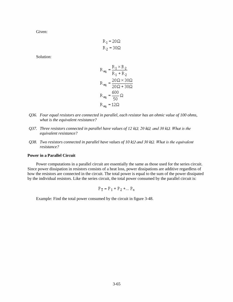
Given:
Solution:
Q36. Four equal resistors are connected in parallel, each resistor has an ohmic value of 100 ohms,what is the equivalent resistance?
Q37. Three resistors connected in parallel have values of 12 N �����N ��DQG����N ��:KDW�LV�WKHequivalent resistance?
Q38. Two resistors connected in parallel have values of 10 N �DQG����N ��:KDW�LV�WKH�HTXLYDOHQWresistance?
Power in a Parallel Circuit
Power computations in a parallel circuit are essentially the same as those used for the series circuit.Since power dissipation in resistors consists of a heat loss, power dissipations are additive regardless ofhow the resistors are connected in the circuit. The total power is equal to the sum of the power dissipatedby the individual resistors. Like the series circuit, the total power consumed by the parallel circuit is:
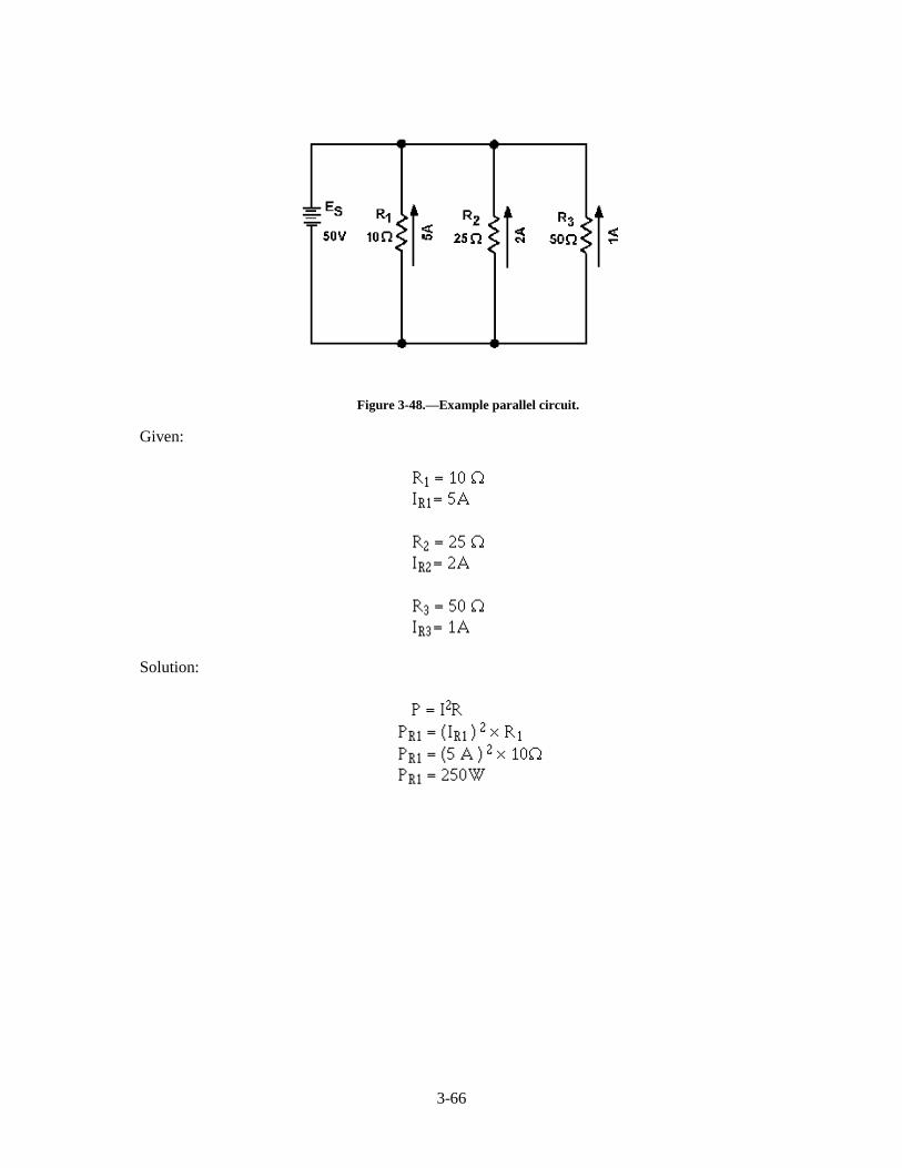
Example: Find the total power consumed by the circuit in figure 3-48.
3-66
Figure 3-48.—Example parallel circuit.
Given:
Solution:
3-67
Since the total current and source voltage are known, the total power can also be computed by:
Given:
Solution:
Equivalent Circuits
In the study of electricity, it is often necessary to reduce a complex circuit into a simpler form. Anycomplex circuit consisting of resistances can be redrawn (reduced) to a basic equivalent circuit containingthe voltage source and a single resistor representing total resistance. This process is called reduction to anEQUIVALENT CIRCUIT.
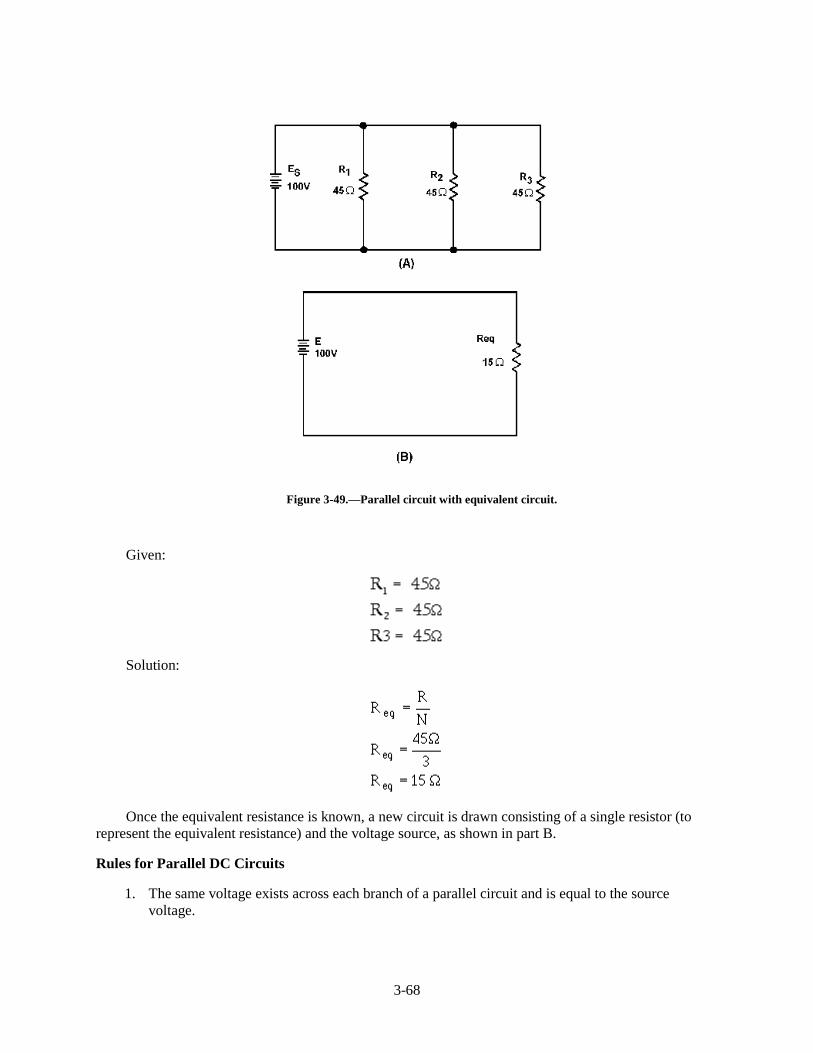
Figure 3-49 shows a parallel circuit with three resistors of equal value and the redrawn equivalentcircuit. The parallel circuit shown in part A shows the original circuit. To create the equivalent circuit,you must first calculate the equivalent resistance.
3-68
Figure 3-49.—Parallel circuit with equivalent circuit.
Given:
Solution:
Once the equivalent resistance is known, a new circuit is drawn consisting of a single resistor (torepresent the equivalent resistance) and the voltage source, as shown in part B.
Rules for Parallel DC Circuits
1. The same voltage exists across each branch of a parallel circuit and is equal to the sourcevoltage.
3-69
2. The current through a branch of a parallel network is inversely proportional to the amount ofresistance of the branch.
3. The total current of a parallel circuit is equal to the sum of the individual branch currents of thecircuit.
4. The total resistance of a parallel circuit is found by the general formula:
or one of the formulas derived from this general formula.
5. The total power consumed in a parallel circuit is equal to the sum of the power consumptions ofthe individual resistances.
SOLVING PARALLEL CIRCUIT PROBLEMS
Problems involving the determination of resistance, voltage, current, and power in a parallel circuitare solved as simply as in a series circuit. The procedure is the same — (1) draw the circuit diagram, (2)state the values given and the values to be found, (3) select the equations to be used in solving for theunknown quantities based upon the known quantities, and (4) substitute the known values in the equationyou have selected and solve for the unknown value.
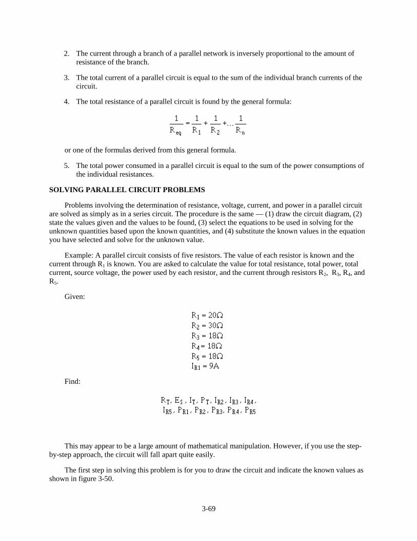
Example: A parallel circuit consists of five resistors. The value of each resistor is known and thecurrent through R1 is known. You are asked to calculate the value for total resistance, total power, totalcurrent, source voltage, the power used by each resistor, and the current through resistors R2, R 3, R4, andR5.
Given:
Find:
This may appear to be a large amount of mathematical manipulation. However, if you use the step-by-step approach, the circuit will fall apart quite easily.
The first step in solving this problem is for you to draw the circuit and indicate the known values asshown in figure 3-50.

3-70
Figure 3-50.—Parallel circuit problem.
There are several ways to approach this problem. With the values you have been given, you couldfirst solve for RT, the power used by R1, or the voltage across R1, which you know is equal to the sourcevoltage and the voltage across each of the other resistors. Solving for RT or the power used by R1 will nothelp in solving for the other unknown values.
Once the voltage across Rl is known, this value will help you calculate other unknowns. Thereforethe logical unknown to solve for is the source voltage (the voltage across R1).
Given:
Solution:
Now that source voltage is known, you can solve for current in each branch.
Given:
3-71
Solution:
Since R 3 = R4 = R5 and the voltage across each branch is the same:
Solving for total resistance.
Given:
3-72
Solution:
An alternate method for solving for RT can be used. By observation, you can see that R 3, R 4, and R5
are of equal ohmic value. Therefore an equivalent resistor can be substituted for these three resistors insolving for total resistance.
Given:
Solution:
The circuit can now be redrawn using a resistor labeled Req1 in place of R 3, R4, and R5 as shown infigure 3-51.

3-73
Figure 3-51.—First equivalent parallel circuit.
An equivalent resistor can be calculated and substituted for Rl and R2 by use of the product over thesum formula.
Given:
Solution:
The circuit is now redrawn again using a resistor labeled Req2 in place of R1 and R2 as shown infigure 3-52.
3-74
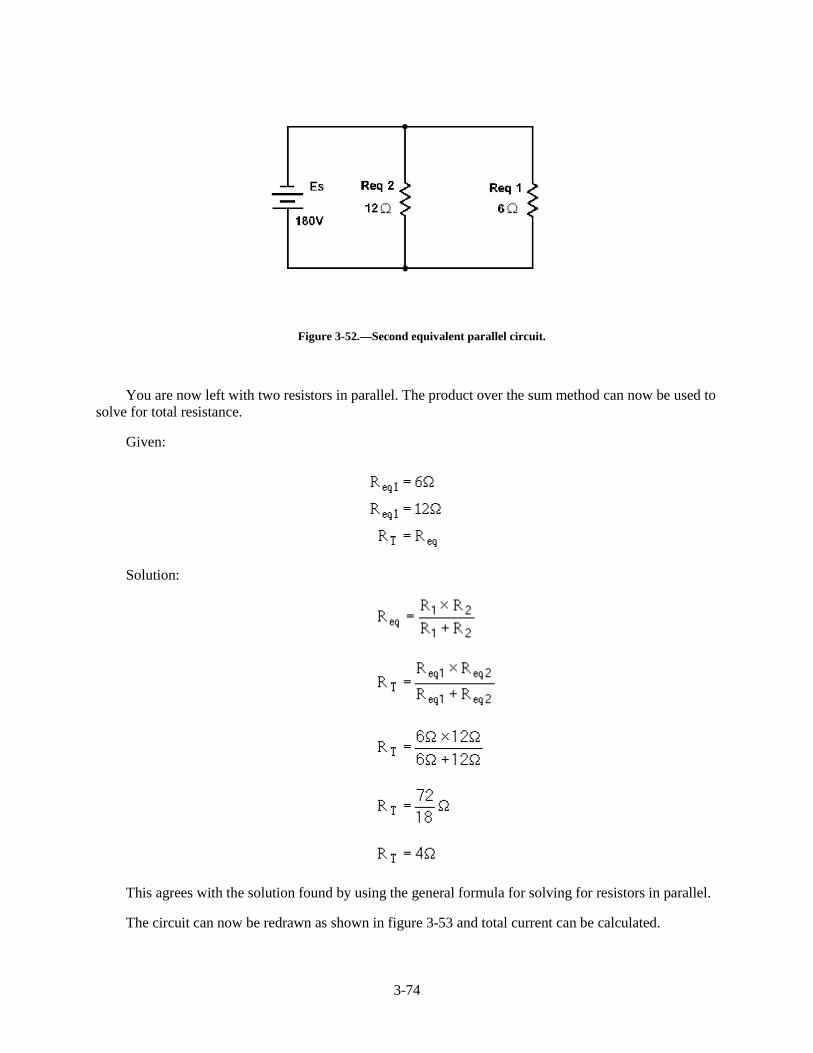
Figure 3-52.—Second equivalent parallel circuit.
You are now left with two resistors in parallel. The product over the sum method can now be used tosolve for total resistance.
Given:
Solution:
This agrees with the solution found by using the general formula for solving for resistors in parallel.
The circuit can now be redrawn as shown in figure 3-53 and total current can be calculated.
3-75
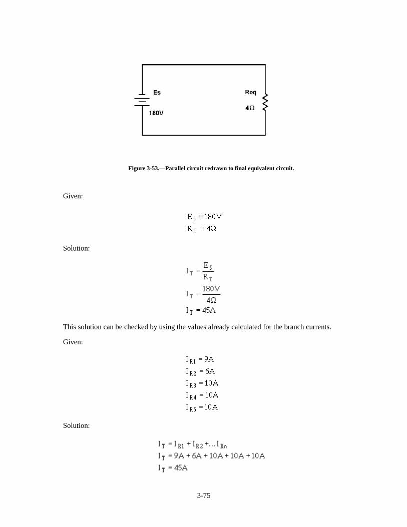
Figure 3-53.—Parallel circuit redrawn to final equivalent circuit.
Given:
Solution:
This solution can be checked by using the values already calculated for the branch currents.
Given:
Solution:
3-76
Now that total current is known, the next logical step is to find total power.
Given:
Solution:
Solving for the power in each branch.
Given:
Solution:
Since IR3 = IR4 = IR5 then, PR3 = PR4 = PR5 = 1800 W. The previous calculation for total power cannow be checked.
3-77
Given:
Solution:
Q39. What term identifies a single resistor that represents total resistance of a complex circuit?
Q40. The total power in both series and parallel circuits is computed with the formula: PT = P1 + P2 +P3 +...Pn. Why can this formula be used for both series and parallel circuits?
Q41. A circuit consists of three resistors connected in parallel across a voltage source. Rl� ��� ��52 =�� ��5�3 � ��� ��DQG�3R3 = 360 watts. Solve for RT, ES and IR2. (Hint: Draw and label the circuitfirst.)
SERIES-PARALLEL DC CIRCUITS
In the preceding discussions, series and parallel dc circuits have been considered separately. Thetechnician will encounter circuits consisting of both series and parallel elements. A circuit of this type isreferred to as a COMBINATION CIRCUIT. Solving for the quantities and elements in a combinationcircuit is simply a matter of applying the laws and rules discussed up to this point.
SOLVING COMBINATION-CIRCUIT PROBLEMS
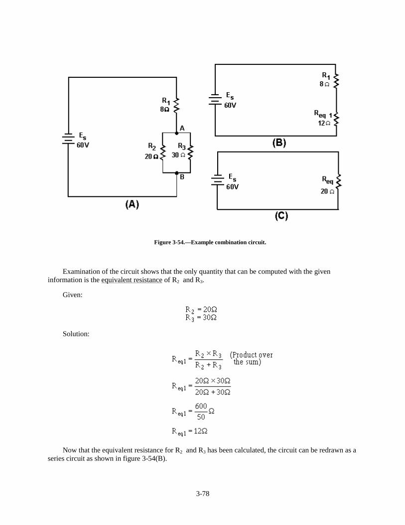
The basic technique used for solving dc combination-circuit problems is the use of equivalentcircuits. To simplify a complex circuit to a simple circuit containing only one load, equivalent circuits aresubstituted (on paper) for the complex circuit they represent. To demonstrate the method used to solvecombination circuit problems, the network shown in figure 3-54(A) will be used to calculate variouscircuit quantities, such as resistance, current, voltage, and power.
3-78
Figure 3-54.—Example combination circuit.
Examination of the circuit shows that the only quantity that can be computed with the giveninformation is the equivalent resistance of R2 and R 3.
Given:
Solution:
Now that the equivalent resistance for R2 and R 3 has been calculated, the circuit can be redrawn as aseries circuit as shown in figure 3-54(B).
3-79
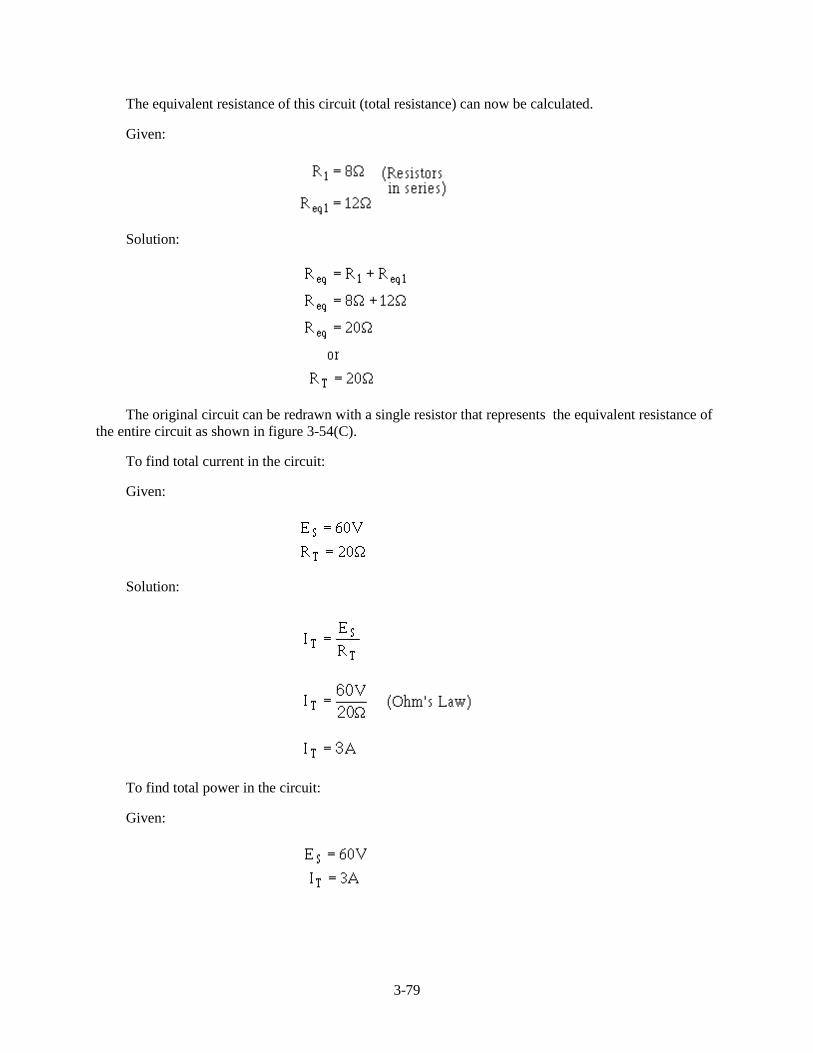
The equivalent resistance of this circuit (total resistance) can now be calculated.
Given:
Solution:
The original circuit can be redrawn with a single resistor that represents the equivalent resistance ofthe entire circuit as shown in figure 3-54(C).
To find total current in the circuit:
Given:
Solution:
To find total power in the circuit:
Given:
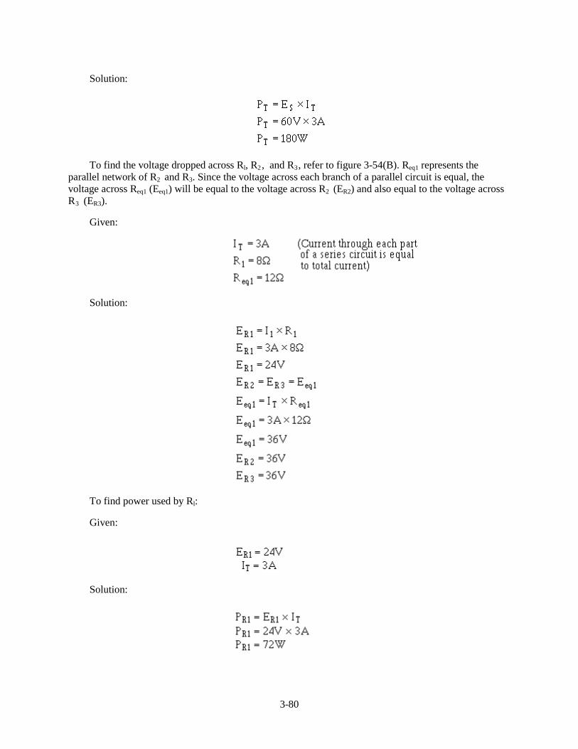
3-80
Solution:
To find the voltage dropped across Rl, R2, and R3, refer to figure 3-54(B). Req1 represents theparallel network of R2 and R 3. Since the voltage across each branch of a parallel circuit is equal, thevoltage across Req1 (Eeq1) will be equal to the voltage across R2 (ER2) and also equal to the voltage acrossR3 (ER3).
Given:
Solution:
To find power used by Rl:
Given:
Solution:
3-81
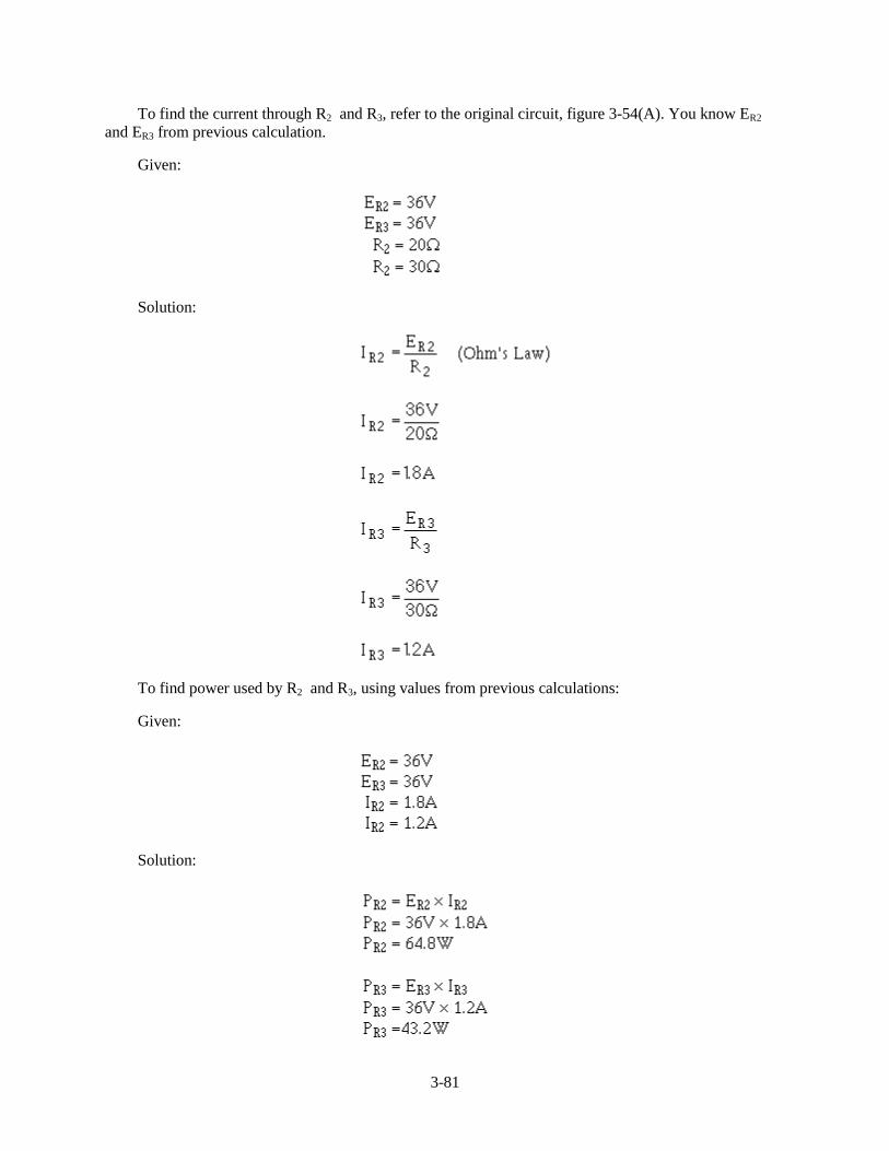
To find the current through R2 and R 3, refer to the original circuit, figure 3-54(A). You know ER2
and ER3 from previous calculation.
Given:
Solution:
To find power used by R2 and R 3, using values from previous calculations:
Given:
Solution:
3-82
Now that you have solved for the unknown quantities in this circuit, you can apply what you havelearned to any series, parallel, or combination circuit. It is important to remember to first look at thecircuit and from observation make your determination of the type of circuit, what is known, and what youare looking for. A minute spent in this manner may save you many unnecessary calculations.
Having computed all the currents and voltages of figure 3-54, a complete description of theoperation of the circuit can be made. The total current of 3 amps leaves the negative terminal of thebattery and flows through the 8-ohm resistor (R1). In so doing, a voltage drop of 24 volts occurs acrossresistor R1. At point A, this 3-ampere current divides into two currents. Of the total current, 1.8 ampsflows through the 20-ohm resistor. The remaining current of 1.2 amps flows from point A, down throughthe 30-ohm resistor to point B. This current produces a voltage drop of 36 volts across the 30-ohmresistor. (Notice that the voltage drops across the 20- and 30-ohm resistors are the same.) The two branchcurrents of 1.8 and 1.2 amps combine at junction B and the total current of 3 amps flows back to thesource. The action of the circuit has been completely described with the exception of power consumed,which could be described using the values previously computed.
It should be pointed out that the combination circuit is not difficult to solve. The key to its solutionlies in knowing the order in which the steps of the solution must be accomplished.
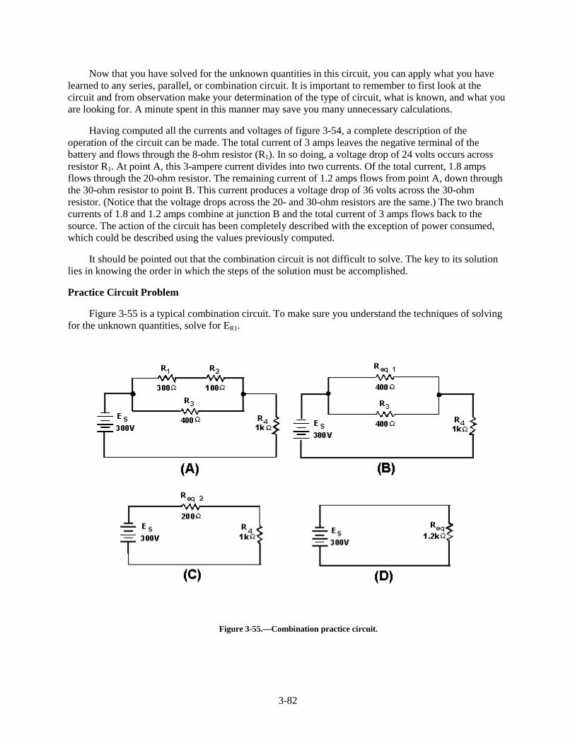
Practice Circuit Problem
Figure 3-55 is a typical combination circuit. To make sure you understand the techniques of solvingfor the unknown quantities, solve for ER1.
Figure 3-55.—Combination practice circuit.

3-83
It is not necessary to solve for all the values in the circuit to compute the voltage drop across resistorR1 (E R1). First look at the circuit and determine that the values given do not provide enough informationto solve for ER1 directly.
If the current through R1 (IR1) is known, then ER1 can be computed by applying the formula:
The following steps will be used to solve the problem.
1. The total resistance (RT) is calculated by the use of equivalent resistance.
Given:
Solution:
Redraw the circuit as shown in figure 3-55(B).
Given:
Solution:
Solution:
3-84
Redraw the circuit as shown in figure 3-55(C).
Given:
Solution:
2. The total current (IT) is now computed.
Given:
Solution:
3. Solve for the voltage dropped across Req2. This represents the voltage dropped across the networkR1, R2, and R 3 in the original circuit.
Given:
Solution:
4. Solve for the current through Req1. (Req1 represents the network R1 and R2 in the original circuit.)Since the voltage across each branch of a parallel circuit is equal to the voltage across theequivalent resistor representing the circuit:
3-85
Given:
Solution:
5. Solve for the voltage dropped across R1 (the quantity you were asked to find). Since Req1
represents the series network of R1 and R2 and total current flows through each resistor in a seriescircuit, IR1 must equal IReq1.
Given:
Solution:
Q42. Refer to figure 3-55(A). If the following resistors were replaced with the values indicated: R1 =��� ��5�3 = lk ��ZKDW�LV�WKH�WRWDO�SRZHU�LQ�WKH�FLUFXLW"�:KDW�LV�(R2?
REDRAWING CIRCUITS FOR CLARITY
You will notice that the schematic diagrams you have been working with have shown parallelcircuits drawn as neat square figures, with each branch easily identified.
In actual practice the wired circuits and more complex schematics are rarely laid out in this simpleform. For this reason, it is important for you to recognize that circuits can be drawn in a variety of ways,and to learn some of the techniques for redrawing them into their simplified form. When a circuit isredrawn for clarity or to its simplest form, the following steps are used.
1. Trace the current paths in the circuit.
2. Label the junctions in the circuit.
3. Recognize points which are at the same potential.
3-86
4. Visualize a rearrangement, "stretching" or "shrinking," of connecting wires.
5. Redraw the circuit into simpler form (through stages if necessary).
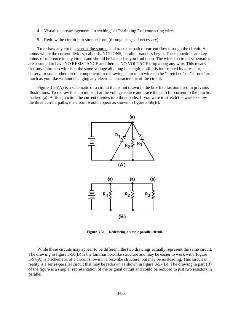
To redraw any circuit, start at the source, and trace the path of current flow through the circuit. Atpoints where the current divides, called JUNCTIONS, parallel branches begin. These junctions are keypoints of reference in any circuit and should be labeled as you find them. The wires in circuit schematicsare assumed to have NO RESISTANCE and there is NO VOLTAGE drop along any wire. This meansthat any unbroken wire is at the same voltage all along its length, until it is interrupted by a resistor,battery, or some other circuit component. In redrawing a circuit, a wire can be "stretched" or "shrunk" asmuch as you like without changing any electrical characteristic of the circuit.
Figure 3-56(A) is a schematic of a circuit that is not drawn in the box-like fashion used in previousillustrations. To redraw this circuit, start at the voltage source and trace the path for current to the junctionmarked (a). At this junction the current divides into three paths. If you were to stretch the wire to showthe three current paths, the circuit would appear as shown in figure 3-56(B).
Figure 3-56.—Redrawing a simple parallel circuit.
While these circuits may appear to be different, the two drawings actually represent the same circuit.The drawing in figure 3-56(B) is the familiar box-like structure and may be easier to work with. Figure3-57(A) is a schematic of a circuit shown in a box-like structure, but may be misleading. This circuit inreality is a series-parallel circuit that may be redrawn as shown in figure 3-57(B). The drawing in part (B)of the figure is a simpler representation of the original circuit and could be reduced to just two resistors inparallel.
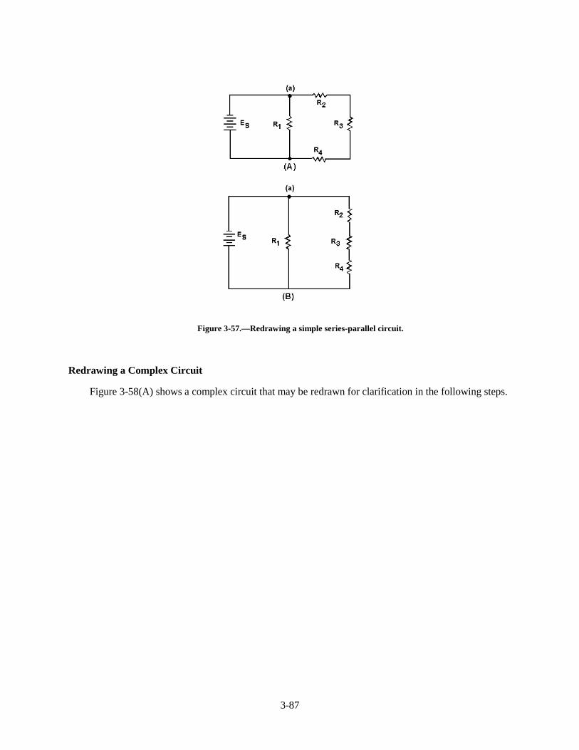
3-87
Figure 3-57.—Redrawing a simple series-parallel circuit.
Redrawing a Complex Circuit
Figure 3-58(A) shows a complex circuit that may be redrawn for clarification in the following steps.
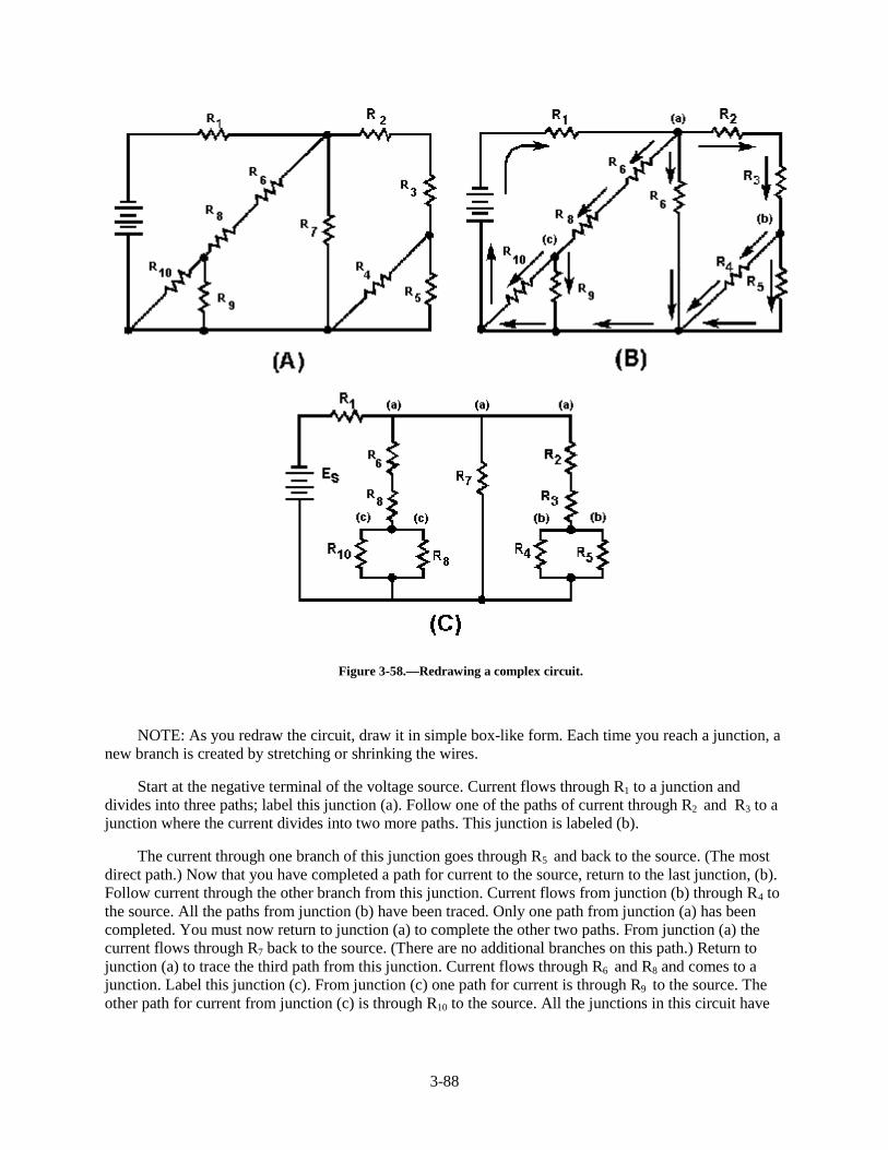
3-88
Figure 3-58.—Redrawing a complex circuit.
NOTE: As you redraw the circuit, draw it in simple box-like form. Each time you reach a junction, anew branch is created by stretching or shrinking the wires.
Start at the negative terminal of the voltage source. Current flows through R1 to a junction anddivides into three paths; label this junction (a). Follow one of the paths of current through R2 and R3 to ajunction where the current divides into two more paths. This junction is labeled (b).
The current through one branch of this junction goes through R5 and back to the source. (The mostdirect path.) Now that you have completed a path for current to the source, return to the last junction, (b).Follow current through the other branch from this junction. Current flows from junction (b) through R4 tothe source. All the paths from junction (b) have been traced. Only one path from junction (a) has beencompleted. You must now return to junction (a) to complete the other two paths. From junction (a) thecurrent flows through R7 back to the source. (There are no additional branches on this path.) Return tojunction (a) to trace the third path from this junction. Current flows through R6 and R8 and comes to ajunction. Label this junction (c). From junction (c) one path for current is through R9 to the source. Theother path for current from junction (c) is through R10 to the source. All the junctions in this circuit have
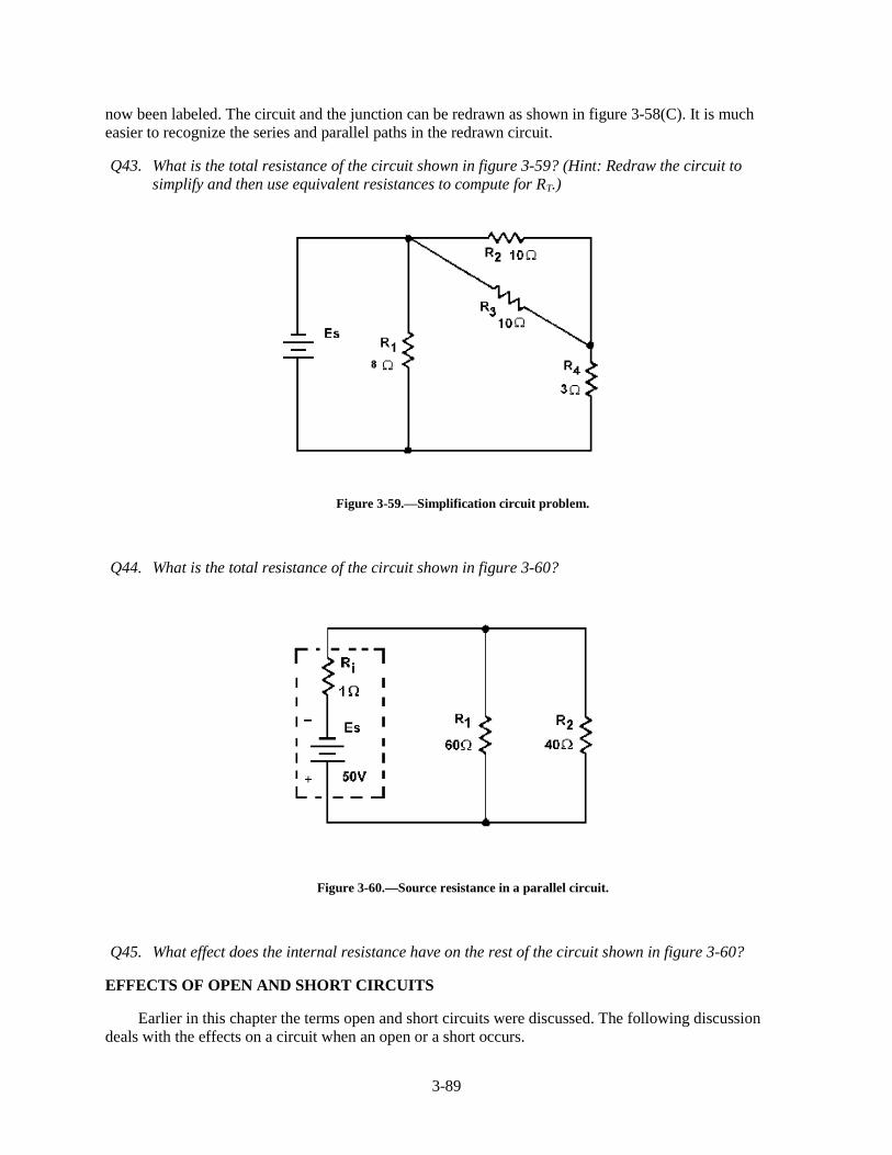
3-89
now been labeled. The circuit and the junction can be redrawn as shown in figure 3-58(C). It is mucheasier to recognize the series and parallel paths in the redrawn circuit.
Q43. What is the total resistance of the circuit shown in figure 3-59? (Hint: Redraw the circuit tosimplify and then use equivalent resistances to compute for RT.)
Figure 3-59.—Simplification circuit problem.
Q44. What is the total resistance of the circuit shown in figure 3-60?
Figure 3-60.—Source resistance in a parallel circuit.
Q45. What effect does the internal resistance have on the rest of the circuit shown in figure 3-60?
EFFECTS OF OPEN AND SHORT CIRCUITS
Earlier in this chapter the terms open and short circuits were discussed. The following discussiondeals with the effects on a circuit when an open or a short occurs.
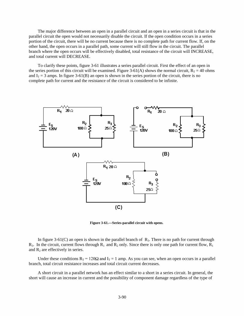
3-90
The major difference between an open in a parallel circuit and an open in a series circuit is that in theparallel circuit the open would not necessarily disable the circuit. If the open condition occurs in a seriesportion of the circuit, there will be no current because there is no complete path for current flow. If, on theother hand, the open occurs in a parallel path, some current will still flow in the circuit. The parallelbranch where the open occurs will be effectively disabled, total resistance of the circuit will INCREASE,and total current will DECREASE.
To clarify these points, figure 3-61 illustrates a series parallel circuit. First the effect of an open inthe series portion of this circuit will be examined. Figure 3-61(A) shows the normal circuit, RT = 40 ohmsand IT = 3 amps. In figure 3-61(B) an open is shown in the series portion of the circuit, there is nocomplete path for current and the resistance of the circuit is considered to be infinite.
Figure 3-61.—Series-parallel circuit with opens.
In figure 3-61(C) an open is shown in the parallel branch of R 3. There is no path for current throughR3. In the circuit, current flows through R1 and R2 only. Since there is only one path for current flow, R1
and R2 are effectively in series.
Under these conditions RT� ���� �DQG�,T = 1 amp. As you can see, when an open occurs in a parallelbranch, total circuit resistance increases and total circuit current decreases.
A short circuit in a parallel network has an effect similar to a short in a series circuit. In general, theshort will cause an increase in current and the possibility of component damage regardless of the type of
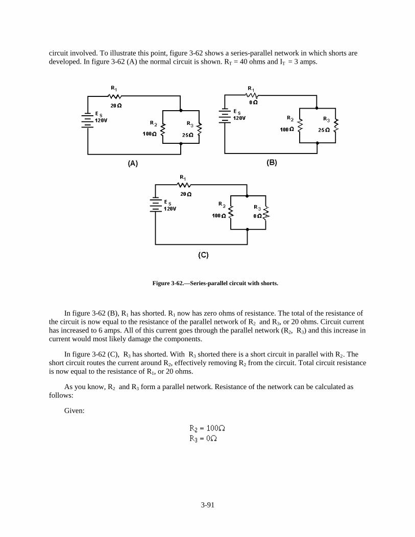
3-91
circuit involved. To illustrate this point, figure 3-62 shows a series-parallel network in which shorts aredeveloped. In figure 3-62 (A) the normal circuit is shown. RT = 40 ohms and IT = 3 amps.
Figure 3-62.—Series-parallel circuit with shorts.
In figure 3-62 (B), R1 has shorted. R1 now has zero ohms of resistance. The total of the resistance ofthe circuit is now equal to the resistance of the parallel network of R2 and R 3, or 20 ohms. Circuit currenthas increased to 6 amps. All of this current goes through the parallel network (R2, R 3) and this increase incurrent would most likely damage the components.
In figure 3-62 (C), R 3 has shorted. With R 3 shorted there is a short circuit in parallel with R2. Theshort circuit routes the current around R2, effectively removing R2 from the circuit. Total circuit resistanceis now equal to the resistance of R1, or 20 ohms.
As you know, R2 and R 3 form a parallel network. Resistance of the network can be calculated asfollows:
Given:
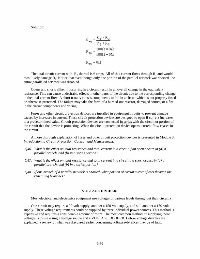
3-92
Solution:
The total circuit current with R 3 shorted is 6 amps. All of this current flows through R1 and wouldmost likely damage R1. Notice that even though only one portion of the parallel network was shorted, theentire paralleled network was disabled.
Opens and shorts alike, if occurring in a circuit, result in an overall change in the equivalentresistance. This can cause undesirable effects in other parts of the circuit due to the corresponding changein the total current flow. A short usually causes components to fail in a circuit which is not properly fusedor otherwise protected. The failure may take the form of a burned-out resistor, damaged source, or a firein the circuit components and wiring.
Fuses and other circuit protection devices are installed in equipment circuits to prevent damagecaused by increases in current. These circuit protection devices are designed to open if current increasesto a predetermined value. Circuit protection devices are connected in series with the circuit or portion ofthe circuit that the device is protecting. When the circuit protection device opens, current flow ceases inthe circuit.
A more thorough explanation of fuses and other circuit protection devices is presented in Module 3,Introduction to Circuit Protection, Control, and Measurement.
Q46. What is the effect on total resistance and total current in a circuit if an open occurs in (a) aparallel branch, and (b) in a series portion?
Q47. What is the effect on total resistance and total current in a circuit if a short occurs in (a) aparallel branch, and (b) in a series portion?
Q48. If one branch of a parallel network is shorted, what portion of circuit current flows through theremaining branches?
VOLTAGE DIVIDERS
Most electrical and electronics equipment use voltages of various levels throughout their circuitry.
One circuit may require a 90-volt supply, another a 150-volt supply, and still another a 180-voltsupply. These voltage requirements could be supplied by three individual power sources. This method isexpensive and requires a considerable amount of room. The most common method of supplying thesevoltages is to use a single voltage source and a VOLTAGE DIVIDER. Before voltage dividers areexplained, a review of what was discussed earlier concerning voltage references may be of help.
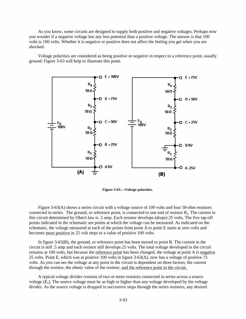
3-93
As you know, some circuits are designed to supply both positive and negative voltages. Perhaps nowyou wonder if a negative voltage has any less potential than a positive voltage. The answer is that 100volts is 100 volts. Whether it is negative or positive does not affect the feeling you get when you areshocked.
Voltage polarities are considered as being positive or negative in respect to a reference point, usuallyground. Figure 3-63 will help to illustrate this point.
Figure 3-63.—Voltage polarities.
Figure 3-63(A) shows a series circuit with a voltage source of 100 volts and four 50-ohm resistorsconnected in series. The ground, or reference point, is connected to one end of resistor R 1. The current inthis circuit determined by Ohm’s law is .5 amp. Each resistor develops (drops) 25 volts. The five tap-offpoints indicated in the schematic are points at which the voltage can be measured. As indicated on theschematic, the voltage measured at each of the points from point A to point E starts at zero volts andbecomes more positive in 25 volt steps to a value of positive 100 volts.
In figure 3-63(B), the ground, or reference point has been moved to point B. The current in thecircuit is still .5 amp and each resistor still develops 25 volts. The total voltage developed in the circuitremains at 100 volts, but because the reference point has been changed, the voltage at point A is negative25 volts. Point E, which was at positive 100 volts in figure 3-63(A), now has a voltage of positive 75volts. As you can see the voltage at any point in the circuit is dependent on three factors; the currentthrough the resistor, the ohmic value of the resistor, and the reference point in the circuit.
A typical voltage divider consists of two or more resistors connected in series across a sourcevoltage (Es). The source voltage must be as high or higher than any voltage developed by the voltagedivider. As the source voltage is dropped in successive steps through the series resistors, any desired
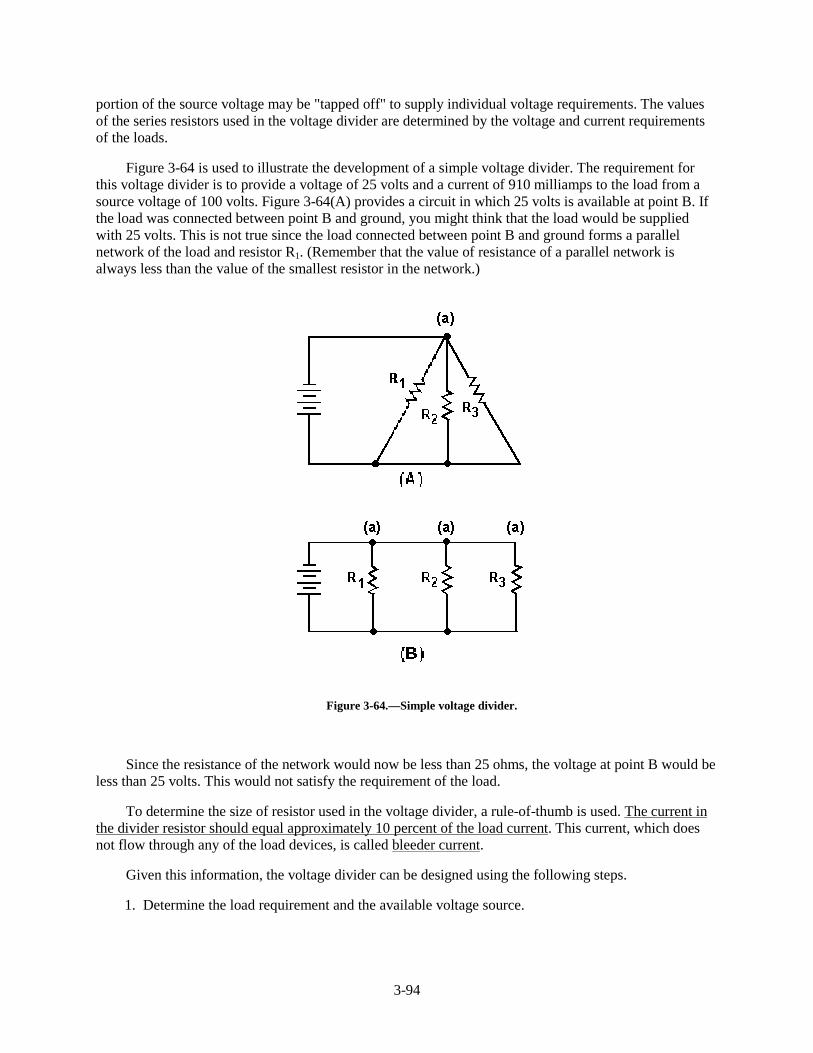
3-94
portion of the source voltage may be "tapped off" to supply individual voltage requirements. The valuesof the series resistors used in the voltage divider are determined by the voltage and current requirementsof the loads.
Figure 3-64 is used to illustrate the development of a simple voltage divider. The requirement forthis voltage divider is to provide a voltage of 25 volts and a current of 910 milliamps to the load from asource voltage of 100 volts. Figure 3-64(A) provides a circuit in which 25 volts is available at point B. Ifthe load was connected between point B and ground, you might think that the load would be suppliedwith 25 volts. This is not true since the load connected between point B and ground forms a parallelnetwork of the load and resistor R1. (Remember that the value of resistance of a parallel network isalways less than the value of the smallest resistor in the network.)
Figure 3-64.—Simple voltage divider.
Since the resistance of the network would now be less than 25 ohms, the voltage at point B would beless than 25 volts. This would not satisfy the requirement of the load.
To determine the size of resistor used in the voltage divider, a rule-of-thumb is used. The current inthe divider resistor should equal approximately 10 percent of the load current. This current, which doesnot flow through any of the load devices, is called bleeder current.
Given this information, the voltage divider can be designed using the following steps.
1. Determine the load requirement and the available voltage source.
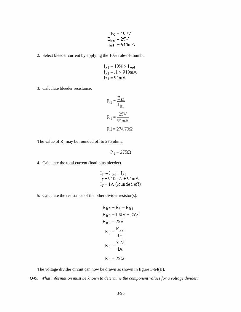
3-95
2. Select bleeder current by applying the 10% rule-of-thumb.
3. Calculate bleeder resistance.
The value of R1 may be rounded off to 275 ohms:
4. Calculate the total current (load plus bleeder).
5. Calculate the resistance of the other divider resistor(s).
The voltage divider circuit can now be drawn as shown in figure 3-64(B).
Q49. What information must be known to determine the component values for a voltage divider?
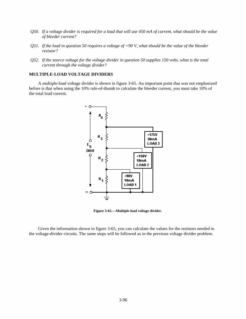
3-96
Q50. If a voltage divider is required for a load that will use 450 mA of current, what should be the valueof bleeder current?
Q51. If the load in question 50 requires a voltage of +90 V, what should be the value of the bleederresistor?
Q52. If the source voltage for the voltage divider in question 50 supplies 150 volts, what is the totalcurrent through the voltage divider?
MULTIPLE-LOAD VOLTAGE DIVIDERS
A multiple-load voltage divider is shown in figure 3-65. An important point that was not emphasizedbefore is that when using the 10% rule-of-thumb to calculate the bleeder current, you must take 10% ofthe total load current.
Figure 3-65.—Multiple-load voltage divider.
Given the information shown in figure 3-65, you can calculate the values for the resistors needed inthe voltage-divider circuits. The same steps will be followed as in the previous voltage divider problem.
3-97
Given:
The bleeder current should be 10% of the total load current.
Solution:
Since the voltage across R1 (ER1) is equal to the voltage requirement for load 1, Ohm’s law can beused to calculate the value for R1.
Solution:
The current through R2 (IR2) is equal to the current through R1 plus the current through load 1.
Solution:
The voltage across R2 (ER2) is equal to the difference between the voltage requirements of load 1 andload 2.
3-98
Ohm’s law can now be used to solve for the value of R 2 .
Solution:
The current through R 3 (IR3) is equal to the current through R2 plus the current through load 2.
The voltage across R 3 (ER3) equals the difference between the voltage requirement of load 3 andload 2.
Ohm’s law can now be used to solve for the value of R3.
Solution:
The current through R4 (IR4) is equal to the current through R 3 plus the current through load 3. IR4 isequal to total circuit current (I T).
The voltage across R4 (ER4) equals the difference between the source voltage and the voltagerequirement of load 3.
3-99
Ohm’s law can now be used to solve for the value of R4.
Solution:
With the calculations just explained, the values of the resistors used in the voltage divider are asfollows:
POWER IN THE VOLTAGE DIVIDER
Power in the voltage divider is an extremely important quantity. The power dissipated by theresistors in the voltage divider should be calculated to determine the power handling requirements of theresistors. Total power of the circuit is needed to determine the power requirement of the source.
The power for the circuit shown in figure 3-65 is calculated as follows:
Given:
Solution:
The power in each resistor is calculated just as for R 1. When the calculations are performed, thefollowing results are obtained:
3-100
To calculate the power for load 1:
Given:
Solution:
The power in each load is calculated just as for load 1. When the calculations are performed, thefollowing results are obtained.
Total power is calculated by summing the power consumed by the loads and the power dissipated bythe divider resistors. The total power in the circuit is 15.675 watts.
The power used by the loads and divider resistors is supplied by the source. This applies to allelectrical circuits; power for all components is supplied by the source.
Since power is the product of voltage and current, the power supplied by the source is equal to thesource voltage multiplied by the total circuit current (Es x IT).
In the circuit of figure 3-65, the total power can be calculated by:
Given:
Solution:
VOLTAGE DIVIDER WITH POSITIVE AND NEGATIVE VOLTAGE REQUIREMENTS
In many cases the load for a voltage divider requires both positive and negative voltages. Positiveand negative voltages can be supplied from a single source voltage by connecting the ground (referencepoint) between two of the divider resistors. The exact point in the circuit at which the reference point isplaced depends upon the voltages required by the loads.

3-101
For example, a voltage divider can be designed to provide the voltage and current to three loads froma given source voltage.
Given:
The circuit is drawn as shown in figure 3-66. Notice the placement of the ground reference point.The values for resistors R1, R 3, and R4 are computed exactly as was done in the last example. IR1 is thebleeder current and can be calculated as follows:
Figure 3-66.—Voltage divider providing both positive and negative voltages.
Solution:
Calculate the value of R1.
3-102
Solution:
Calculate the current through R2 using Kirchhoff’s current law.
At point A:
(or 195mA leaving point A)
Since ER2 = E load 2, you can calculate the value of R2.
Solution:
Calculate the current through R 3.
The voltage across R 3 (ER3) equals the difference between the voltage requirements of loads 3 and 2.
Solution:
Calculate the value of R3.
3-103
Solution:
Calculate the current through R4.
The voltage across ER4 equals the source voltage (Es) minus the voltage requirement of load 3 andthe voltage requirement of load 1. Remember Kirchhoff’s voltage law which states that the sum of thevoltage drops and emfs around any closed loop is equal to zero.
Solution:
Calculate the value of R4.
Solution:
With the calculations just explained, the values of the resistors used in the voltage /divider are as
follows:
From the information just calculated, any other circuit quantity, such as power, total current, orresistance of the load, could be calculated.
3-104
PRACTICAL APPLICATION OF VOLTAGE DIVIDERS
In actual practice the computed value of the bleeder resistor does not always come out to an evenvalue. Since the rule-of-thumb for bleeder current is only an estimated value, the bleeder resistor can beof a value close to the computed value. (If the computed value of the resistance were 510 ohms, a 500-ohm resistor could be used.) Once the actual value of the bleeder resistor is selected, the bleeder currentmust be recomputed. The voltage developed by the bleeder resistor must be equal to the voltagerequirement of the load in parallel with the bleeder resistor.
The value of the remaining resistors in the voltage divider is computed from the current through theremaining resistors and the voltage across them. These values must be used to provide the requiredvoltage and current to the loads.
If the computed values for the divider resistors are not even values; series, parallel, or series-parallelnetworks can be used to provide the required resistance.
Example: A voltage divider is required to supply two loads from a 190.5 volts source. Load 1requires +45 volts and 210 milliamps; load 2 requires +165 volts and 100 milliamps.
Calculate the bleeder current using the rule-of-thumb.
Given:
Solution:
Calculate the ohmic value of the bleeder resistor.
Given:
Solution:
Since it would be difficult to find a resistor of 1451.6 ohms, a practical choice for R1 is 1500 ohms.
Calculate the actual bleeder current using the selected value for R1.
3-105
Given:
Solution:
Using this value for IR1, calculate the resistance needed for the next divider resistor. The current (IR2)is equal to the bleeder current plus the current used by load 1.
Given:
Solution:
The voltage across R2 (ER2) is equal to the difference between the voltage requirements of loads 2and 1, or 120 volts.
Calculate the value of R2.
Given:
Solution:
3-106
The value of the final divider resistor is calculated with I R3 (IR2 + I load 2) equal to 340 mA and E R3
(Es - E load 2) equal to 25.5V.
Given:
Solution:
A 75-ohm resistor may not be easily obtainable, so a network of resistors equal to 75 ohms can beused in place of R 3.
Any combination of resistor values adding up to 75 ohms could be placed in series to develop therequired network. For example, if you had two 37.5-ohm resistors, you could connect them in series to geta network of 75 ohms. One 50-ohm and one 25-ohm resistor or seven 10-ohm and one 5-ohm resistorcould also be used.
A parallel network could be constructed from two 150-ohm resistors or three 225-ohm resistors.Either of these parallel networks would also be a network of 75 ohms.
The network used in this example will be a series-parallel network using three 50-ohm resistors.
With the information given, you should be able to draw this voltage divider network.
Once the values for the various divider resistors have been selected, you can compute the powerused by each resistor using the methods previously explained. When the power used by each resistor isknown, the wattage rating required of each resistor determines the physical size and type needed for thecircuit. This circuit is shown in figure 3-67.
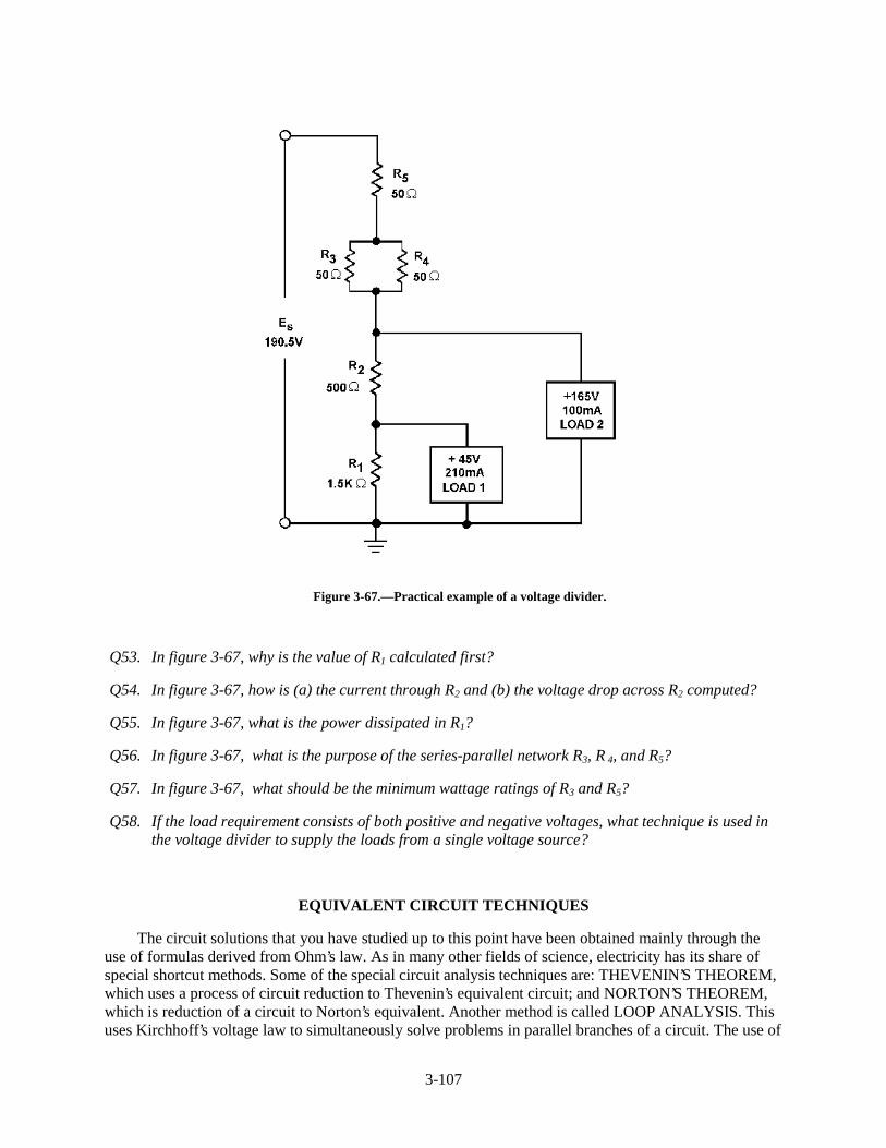
3-107
Figure 3-67.—Practical example of a voltage divider.
Q53. In figure 3-67, why is the value of R1 calculated first?
Q54. In figure 3-67, how is (a) the current through R2 and (b) the voltage drop across R2 computed?
Q55. In figure 3-67, what is the power dissipated in R1?
Q56. In figure 3-67, what is the purpose of the series-parallel network R 3, R 4, and R5?
Q57. In figure 3-67, what should be the minimum wattage ratings of R 3 and R 5 ?
Q58. If the load requirement consists of both positive and negative voltages, what technique is used inthe voltage divider to supply the loads from a single voltage source?
EQUIVALENT CIRCUIT TECHNIQUES
The circuit solutions that you have studied up to this point have been obtained mainly through theuse of formulas derived from Ohm’s law. As in many other fields of science, electricity has its share ofspecial shortcut methods. Some of the special circuit analysis techniques are: THEVENIN’S THEOREM,which uses a process of circuit reduction to Thevenin’s equivalent circuit; and NORTON’S THEOREM,which is reduction of a circuit to Norton’s equivalent. Another method is called LOOP ANALYSIS. Thisuses Kirchhoff’s voltage law to simultaneously solve problems in parallel branches of a circuit. The use of
3-108
these methods should be reserved until you have become thoroughly familiar with the methods coveredthus far in this chapter. You may want to explore some of the special techniques later in your career.
ELECTRICAL SAFETY
Safety precautions must always be observed by persons working around electric circuits andequipment to avoid injury from electric shock. Detailed safety precautions are contained in NAVMATP-5l00, Safety Precautions for Shore Activities and OPNAVINST 5l00-19, Navy Safety Precautions forForces Afloat.
The danger of shock from a 450-volt ac electrical service system is well recognized by operatingpersonnel. This is shown by the relatively low number of reports of serious shock received from thisvoltage, despite its widespread use. On the other hand, a number of fatalities have been reported due tocontact with low-voltage circuits. Despite a fairly widespread, but totally unfounded, popular belief to thecontrary, low-voltage circuits (115 volts and below) are very dangerous and can cause death when theresistance of the body is lowered. Fundamentally, current, rather than voltage, is the measure of shockintensity. The passage of even a very small current through a vital part of the human body can causeDEATH. The voltage necessary to produce the fatal current is dependent upon the resistance of the body,contact conditions, the path through the body, etc. For example, when a 60-hertz alternating current, ispassed through a human body from hand to hand or from hand to foot, and the current is graduallyincreased, it will cause the following effects: At about 1 milliampere (0.001 ampere), the shock can befelt; at about 10 milliamperes (0.01 ampere), the shock is of sufficient intensity to prevent voluntarycontrol of the muscles; and at about 100 milliamperes (0.1 ampere) the shock is fatal if it lasts for 1second or more. The above figures are the results of numerous investigations and are approximatebecause individuals differ in their resistance to electrical shock. It is most important to recognize that theresistance of the human body cannot be relied upon to prevent a fatal shock from 115 volts or less—FATALITIES FROM VOLTAGES AS LOW AS 30 VOLTS HAVE BEEN RECORDED. Tests haveshown that body resistance under unfavorable conditions may be as low as 300 ohms, and possibly as lowas 100 ohms from temple to temple if the skin is broken.
Conditions aboard ship add to the chance of receiving an electrical shock. Aboard ship the body islikely to be in contact with the metal structure of the ship and the body resistance may be low because ofperspiration or damp clothing. Extra care and awareness of electrical hazards aboard ship are needed.
Short circuits can be caused by accidentally placing or dropping a metal tool, rule, flashlight case, orother conducting article across an energized line. The arc and fire which result, even on relatively low-voltage circuits, may cause extensive damage to equipment and serious injury to personnel.
Since ship service power distribution systems are designed to be ungrounded, many persons believeit is safe to touch one conductor, since no electrical current would flow. This is not true, since thedistribution system is not totally isolated from the hull of the ship. If one conductor of an ungroundedelectrical system is touched while the body is in contact with the hull of the ship or other metal equipmentenclosure, a fatal electric current may pass through the body. ALL LIVE ELECTRIC CIRCUITS SHALLBE TREATED AS POTENTIAL HAZARDS AT ALL TIMES.
DANGER SIGNALS
Personnel should constantly be on the alert for any signs which might indicate a malfunction ofelectric equipment. Besides the more obvious visual signs, the reaction of other senses, such as hearing,smell, and touch, should also make you aware of possible electrical malfunctions. Examples of signswhich you must be alert for are: fire, smoke, sparks, arcing, or an unusual sound from an electric motor.
3-109
Frayed and damaged cords or plugs; receptacles, plugs, and cords which feel warm to the touch; slightshocks felt when handling electrical equipment; unusually hot running electric motors and other electricalequipment; an odor of burning or overheated insulation; electrical equipment which either fails to operateor operates irregularly; and electrical equipment which produces excessive vibrations are also indicationsof malfunctions. When any of the above signs are noted, they are to be reported immediately to aqualified technician. DO NOT DELAY. Do not operate faulty equipment. Above all, do not attempt tomake any repairs yourself if you are not qualified to do so. Stand clear of any suspected hazard andinstruct others to do likewise.
• Warning Signs—They have been placed for your protection. To disregard them is to invitepersonal injury as well as possible damage to equipment. Switches and receptacles with atemporary warning tag, indicating work is being performed, are not to be touched.
• Working Near Electrical Equipment—When work must be performed in the immediate vicinityof electrical equipment, check with the technician responsible for the maintenance of theequipment so you can avoid any potential hazards of which you may not be immediately aware.
• Authorized Personnel Only—Because of the danger of fire, damage to equipment, and injury topersonnel, all repair and maintenance work on electrical equipment shall be done only byauthorized persons. Keep your hands off of all equipment which you have not been specificallyauthorized to handle. Particularly stay clear of electrical equipment opened for inspection,testing, or servicing.
• Circuit Breakers and Fuses—Covers for all fuse boxes, junction boxes, switch boxes, and wiringaccessories should be kept closed. Any cover which is not closed or is missing should bereported to the technician responsible for its maintenance. Failure to do so may result in injury topersonnel or damage to equipment in the event accidental contact is made with exposed livecircuits.
ELECTRICAL FIRES
Carbon dioxide (CO2) is used in fighting electrical fires. It is nonconductive and, therefore, the safestto use in terms of electrical safety. It also offers the least likelihood of damaging equipment. However, ifthe discharge horn of a CO2 extinguisher is allowed to accidentally touch an energized circuit, the hornmay transmit a shock to the person handling the extinguisher.
The very qualities which cause CO2 to be a valuable extinguishing agent also make it dangerous tolife. When it replaces oxygen in the air to the extent that combustion cannot be sustained, respiration alsocannot be sustained. Exposure of a person to an atmosphere of high concentration of CO2 will causesuffocation.
FIRST AID FOR ELECTRIC SHOCK
A person who has stopped breathing is not necessarily dead, but is in immediate danger. Life isdependent upon oxygen, which is breathed into the lungs and then carried by the blood to every body cell.Since body cells cannot store oxygen, and since the blood can hold only a limited amount (and that onlyfor a short time), death will surely result from continued lack of breathing.
However, the heart may continue to beat for some time after breathing has stopped, and the bloodmay still be circulated to the body cells. Since the blood will, for a short time, contain a small supply of
3-110
oxygen, the body cells will not die immediately. For a very few minutes, there is some chance that theperson’s life may be saved.
The process by which a person who has stopped breathing can be saved is called ARTIFICIALVENTILATION (RESPIRATION).
The purpose of artificial ventilation is to force air out of the lungs and into the lungs, in rhythmicalternation, until natural breathing is reestablished. Artificial ventilation should be given only whennatural breathing has stopped; it should NOT be given to any person who is breathing naturally. Youshould not assume that an individual who is unconscious due to electrical shock has stopped breathing. Totell if someone suffering from an electrical shock is breathing, place your hands on the person’s sides, atthe level of the lowest ribs. If the victim is breathing, you will usually be able to feel the movement.Remember: DO NOT GIVE ARTIFICIAL VENTILATION TO A PERSON WHO IS BREATHINGNATURALLY.
Records show that seven out of ten victims of electric shock were revived when artificial respirationwas started in less than 3 minutes. After 3 minutes, the chances of revival decrease rapidly.
Once it has been determined that breathing has stopped, the person nearest the victim should start theartificial ventilation without delay and send others for assistance and medical aid. The only logical,permissible delay is that required to free the victim from contact with the electricity in the quickest, safestway. This step, while it must be taken quickly, must be done with great care; otherwise, there may be twovictims instead of one. In the case of portable electric tools, lights, appliances, equipment, or portableoutlet extensions, this should be done by turning off the supply switch or by removing the plug from itsreceptacle. If the switch or receptacle cannot be quickly located, the suspected electrical device may bepulled free of the victim. Other persons arriving on the scene must be clearly warned not to touch thesuspected equipment until it is deenergized. Aid should be enlisted to unplug the device as soon aspossible. The injured person should be pulled free of contact with stationary equipment (such as a busbar) if the equipment cannot be quickly deenergized, or if considerations of military operation or unitsurvival prevent immediate shutdown of the circuits.
This can be done quickly and safely by carefully applying the following procedures:
1. Protect yourself with dry insulating material.
2. Use a dry board, belt, clothing, or other available nonconductive material to free the victim fromelectrical contact. DO NOT TOUCH THE VICTIM UNTIL THE SOURCE OF ELECTRICITYHAS BEEN REMOVED.
Once the victim has been removed from the electrical source, it should be determined, if the personis breathing. If the person is not breathing, a method of artificial ventilation is used.
Sometimes victims of electrical shock suffer cardiac arrest (heart stoppage) as well as loss ofbreathing. Artificial ventilation alone is not enough in cases where the heart has stopped. A techniqueknown as Cardiopulmonary Resuscitation (CPR) has been developed to provide aid to a person who hasstopped breathing and suffered a cardiac arrest. Because you most likely will be working in the field ofelectricity, the risk of electrical shock is higher than most other Navy occupations. You should, at yourearliest opportunity, learn the technique of CPR.
CPR is relatively easy to learn and is taught in courses available from the American Red Cross, someNavy Medical Departments, and in the Standard First Aid Training Course (NAVEDTRA 12081).
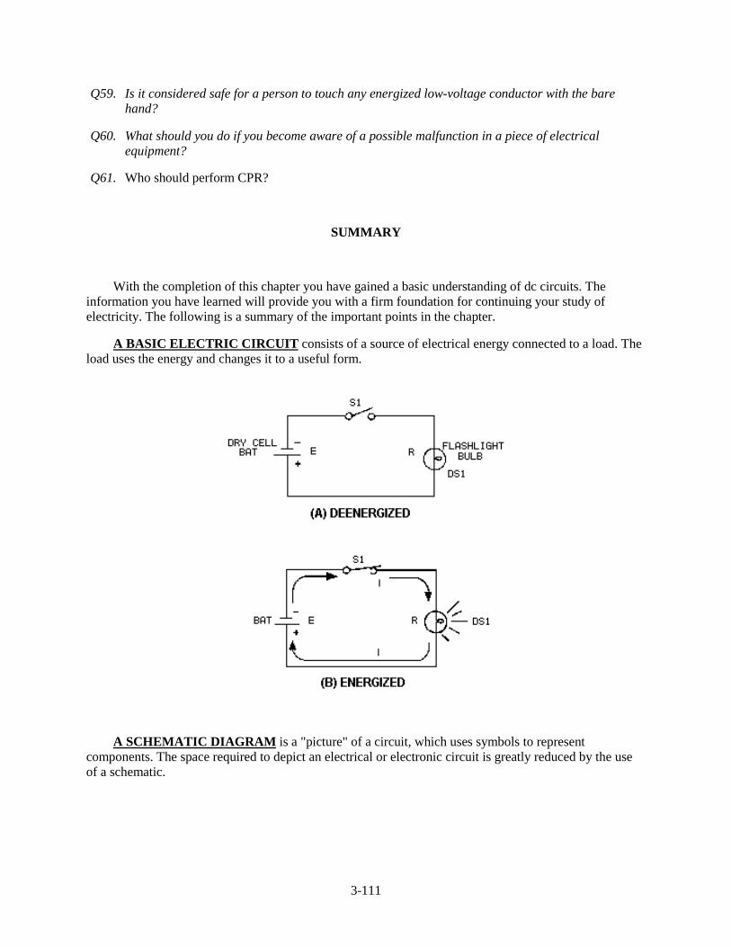
3-111
Q59. Is it considered safe for a person to touch any energized low-voltage conductor with the barehand?
Q60. What should you do if you become aware of a possible malfunction in a piece of electricalequipment?
Q61. Who should perform CPR?
SUMMARY
With the completion of this chapter you have gained a basic understanding of dc circuits. Theinformation you have learned will provide you with a firm foundation for continuing your study ofelectricity. The following is a summary of the important points in the chapter.
A BASIC ELECTRIC CIRCUIT consists of a source of electrical energy connected to a load. Theload uses the energy and changes it to a useful form.
A SCHEMATIC DIAGRAM is a "picture" of a circuit, which uses symbols to representcomponents. The space required to depict an electrical or electronic circuit is greatly reduced by the useof a schematic.
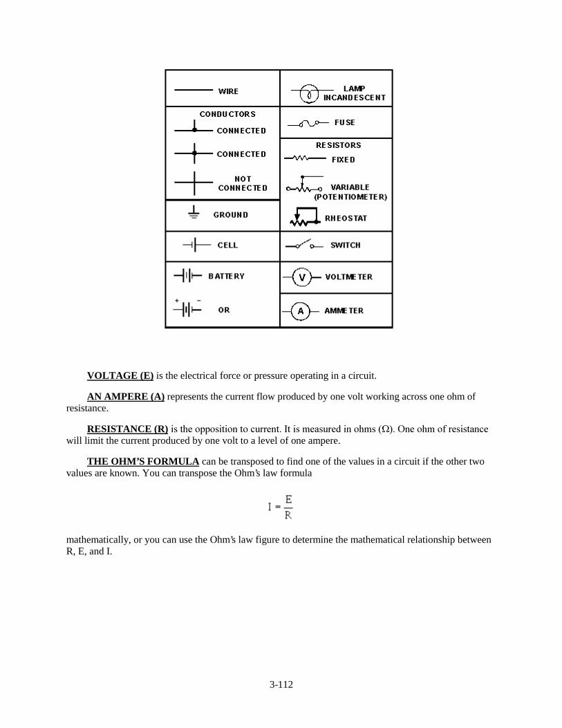
3-112
VOLTAGE (E) is the electrical force or pressure operating in a circuit.
AN AMPERE (A) represents the current flow produced by one volt working across one ohm ofresistance.
RESISTANCE (R)�LV�WKH�RSSRVLWLRQ�WR�FXUUHQW��,W�LV�PHDVXUHG�LQ�RKPV�� ���2QH�RKP�RI�UHVLVWDQFHwill limit the current produced by one volt to a level of one ampere.
THE OHM’S FORMULA can be transposed to find one of the values in a circuit if the other twovalues are known. You can transpose the Ohm’s law formula
mathematically, or you can use the Ohm’s law figure to determine the mathematical relationship betweenR, E, and I.
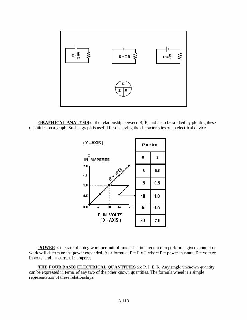
3-113
GRAPHICAL ANALYSIS of the relationship between R, E, and I can be studied by plotting thesequantities on a graph. Such a graph is useful for observing the characteristics of an electrical device.
POWER is the rate of doing work per unit of time. The time required to perform a given amount ofwork will determine the power expended. As a formula, P = E x I, where P = power in watts, E = voltagein volts, and I = current in amperes.
THE FOUR BASIC ELECTRICAL QUANTITIES are P, I, E, R. Any single unknown quantitycan be expressed in terms of any two of the other known quantities. The formula wheel is a simplerepresentation of these relationships.
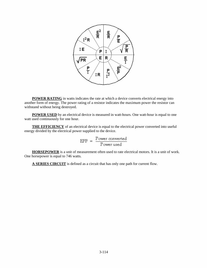
3-114
POWER RATING in watts indicates the rate at which a device converts electrical energy intoanother form of energy. The power rating of a resistor indicates the maximum power the resistor canwithstand without being destroyed.
POWER USED by an electrical device is measured in watt-hours. One watt-hour is equal to onewatt used continuously for one hour.
THE EFFICIENCY of an electrical device is equal to the electrical power converted into usefulenergy divided by the electrical power supplied to the device.
HORSEPOWER is a unit of measurement often used to rate electrical motors. It is a unit of work.One horsepower is equal to 746 watts.
A SERIES CIRCUIT is defined as a circuit that has only one path for current flow.
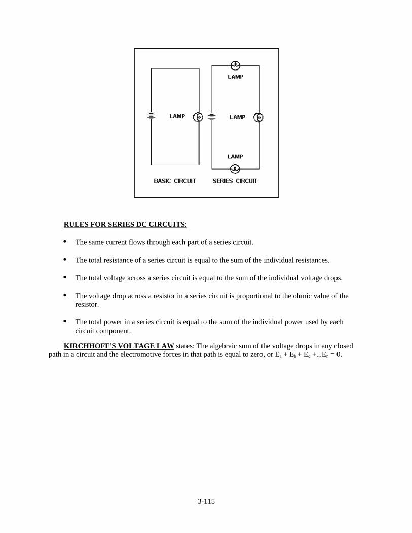
3-115
RULES FOR SERIES DC CIRCUITS:
• The same current flows through each part of a series circuit.
• The total resistance of a series circuit is equal to the sum of the individual resistances.
• The total voltage across a series circuit is equal to the sum of the individual voltage drops.
• The voltage drop across a resistor in a series circuit is proportional to the ohmic value of theresistor.
• The total power in a series circuit is equal to the sum of the individual power used by eachcircuit component.
KIRCHHOFF’S VOLTAGE LAW states: The algebraic sum of the voltage drops in any closedpath in a circuit and the electromotive forces in that path is equal to zero, or Ea + Eb + Ec +...En = 0.

3-116
VOLTAGE POLARITIES must be used when applying Kirchhoff’s voltage law. The point atwhich current enters a load (resistor) is considered negative with respect to the point at which currentleaves the load.
SERIES AIDING VOLTAGES cause current to flow in the same direction; thus the voltages areadded.
SERIES OPPOSING VOLTAGES tend to force current to flow in opposite directions; thus theequivalent voltage is the difference between the opposing voltages.
A REFERENCE POINT is a chosen point in a circuit to which all other points are compared.
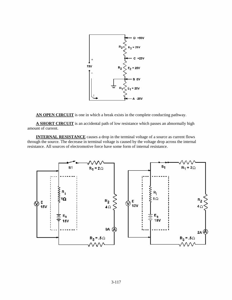
3-117
AN OPEN CIRCUIT is one in which a break exists in the complete conducting pathway.
A SHORT CIRCUIT is an accidental path of low resistance which passes an abnormally highamount of current.
INTERNAL RESISTANCE causes a drop in the terminal voltage of a source as current flowsthrough the source. The decrease in terminal voltage is caused by the voltage drop across the internalresistance. All sources of electromotive force have some form of internal resistance.
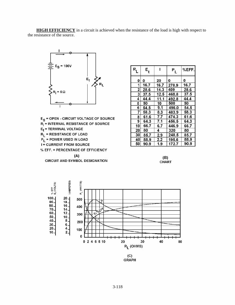
3-118
HIGH EFFICIENCY in a circuit is achieved when the resistance of the load is high with respect tothe resistance of the source.
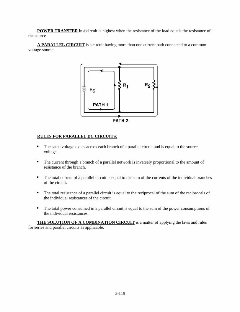
3-119
POWER TRANSFER in a circuit is highest when the resistance of the load equals the resistance ofthe source.
A PARALLEL CIRCUIT is a circuit having more than one current path connected to a commonvoltage source.
RULES FOR PARALLEL DC CIRCUITS:
• The same voltage exists across each branch of a parallel circuit and is equal to the sourcevoltage.
• The current through a branch of a parallel network is inversely proportional to the amount ofresistance of the branch.
• The total current of a parallel circuit is equal to the sum of the currents of the individual branchesof the circuit.
• The total resistance of a parallel circuit is equal to the reciprocal of the sum of the reciprocals ofthe individual resistances of the circuit.
• The total power consumed in a parallel circuit is equal to the sum of the power consumptions ofthe individual resistances.
THE SOLUTION OF A COMBINATION CIRCUIT is a matter of applying the laws and rulesfor series and parallel circuits as applicable.
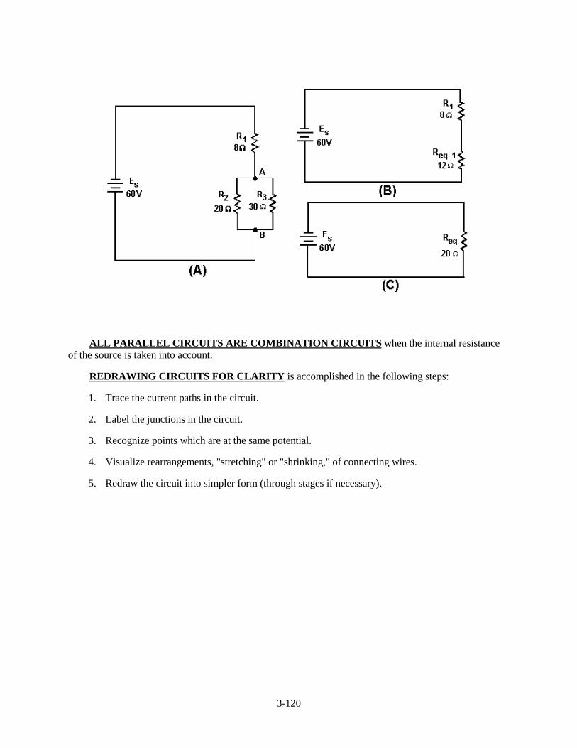
3-120
ALL PARALLEL CIRCUITS ARE COMBINATION CIRCUITS when the internal resistanceof the source is taken into account.
REDRAWING CIRCUITS FOR CLARITY is accomplished in the following steps:
1. Trace the current paths in the circuit.
2. Label the junctions in the circuit.
3. Recognize points which are at the same potential.
4. Visualize rearrangements, "stretching" or "shrinking," of connecting wires.
5. Redraw the circuit into simpler form (through stages if necessary).

3-121
EQUIPMENT PROTECTION from short-circuit current is accomplished by use of fuses and othercircuit protection devices.
A VOLTAGE DIVIDER is a series circuit in which desired portions of the source voltage may betapped off for use in equipment. Both negative and positive voltage can be provided to the loads by theproper selection of the reference point (ground).
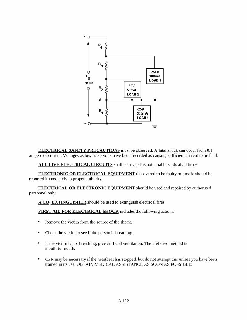
3-122
ELECTRICAL SAFETY PRECAUTIONS must be observed. A fatal shock can occur from 0.1ampere of current. Voltages as low as 30 volts have been recorded as causing sufficient current to be fatal.
ALL LIVE ELECTRICAL CIRCUITS shall be treated as potential hazards at all times.
ELECTRONIC OR ELECTRICAL EQUIPMENT discovered to be faulty or unsafe should bereported immediately to proper authority.
ELECTRICAL OR ELECTRONIC EQUIPMENT should be used and repaired by authorizedpersonnel only.
A CO2 EXTINGUISHER should be used to extinguish electrical fires.
FIRST AID FOR ELECTRICAL SHOCK includes the following actions:
• Remove the victim from the source of the shock.
• Check the victim to see if the person is breathing.
• If the victim is not breathing, give artificial ventilation. The preferred method ismouth-to-mouth.
• CPR may be necessary if the heartbeat has stopped, but do not attempt this unless you have beentrained in its use. OBTAIN MEDICAL ASSISTANCE AS SOON AS POSSIBLE.
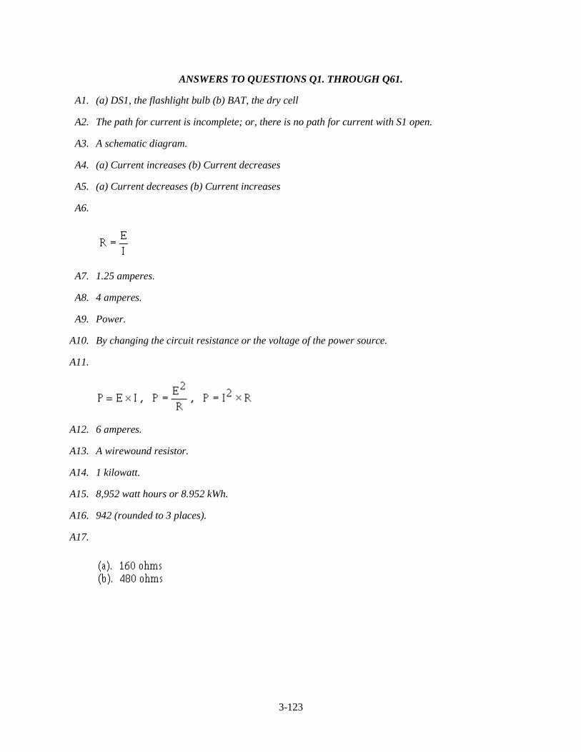
3-123
ANSWERS TO QUESTIONS Q1. THROUGH Q61.
A1. (a) DS1, the flashlight bulb (b) BAT, the dry cell
A2. The path for current is incomplete; or, there is no path for current with S1 open.
A3. A schematic diagram.
A4. (a) Current increases (b) Current decreases
A5. (a) Current decreases (b) Current increases
A6.
A7. 1.25 amperes.
A8. 4 amperes.
A9. Power.
A10. By changing the circuit resistance or the voltage of the power source.
A11.
A12. 6 amperes.
A13. A wirewound resistor.
A14. 1 kilowatt.
A15. 8,952 watt hours or 8.952 kWh.
A16. 942 (rounded to 3 places).
A17.
3-124
A18.
A19.
A20. The source voltage would have to be increased to 640 volts.
A21.
A22. The point at which current enters the resistor is assigned a negative polarity and the point at whichcurrent leaves the resistor is assigned a positive polarity.
A23. 2 amperes.
A24. 120 volts.
A25. 50 volts.
A26. Zero volts.
A27. A circuit where there is no longer a complete path for current flow.
A28. An accidental path of low resistance which passes an abnormally high amount of current.
A29. The internal (source) resistance of the battery will drop some of the voltage.
A30. When the load resistance equals the source resistance.
A31. 50 percent.
3-125
A32.
A33. 60 volts.
A34. Total current in a series circuit flows through every circuit component but in a parallel circuit totalcurrent divides among the available paths.
A35. Whether the current is entering the junction (+) or leaving the junction (-).
A36.
A37.
A38.
A39. Equivalent resistor or Req.
A40. In both cases all the power used in the circuit must come from the source.
A41.
A42. PT = 60 W, ER2 = 10 V.
A43. � �
A44. �� �
3-126
A45. Because of the 2-volt drop across the internal resistance, only 48 volts is available for the rest ofthe circuit.
A46. (a) Total resistance increases, total current decreases (b) Total resistance becomes infinite, totalcurrent is equal to zero
A47. (a) Total resistance decreases, total current increases (b) Total resistance decreases, total currentincreases
A48. None.
A49. The source voltage and load requirements (voltage and current).
A50. 45 mA rule-of-thumb.
A51. 2 N �
A52. 495 mA.
A53. R1 is the bleeder resistor. Bleeder current must be known before any of the remaining dividerresistor ohmic values can be computed.
A54. (a) By adding the bleeder current (IR1) and the current through load 1(b) By subtracting the voltageof load 1 from the voltage of load 2.
A55. 1.35 watts.
A56. The series-parallel network drops the remaining source voltage and is used to take the place of asingle resistor (75 ohms) when the required ohmic value is not available in a single resistor.
A57. R3 = 2 watts; R5 = 6 watts.
A58. The ground (reference point) is placed in the proper point in the voltage divider so that positiveand negative voltages are supplied.
A59. NEVER! All energized electric circuits should be considered potentially dangerous.
A60. You should immediately report this condition to a qualified technician.
A61. Only trained, qualified personnel.