fusion technology institute university of wisconsin
TRANSCRIPT

•
W I S C O N SI N
•
FU
SIO
N•
TECHNOLOGY• INS
TIT
UT
E
FUSION TECHNOLOGY INSTITUTE
UNIVERSITY OF WISCONSIN
MADISON WISCONSIN
Activation of W-Based Divertors with Thin Re andMo Coatings for Fusion Applications
A. Jaber, L. El-Guebaly, A. Robinson, D. Henderson, T. Renk
March 2011
UWFDM-1382

Activation of W-Based Divertors with Thin Re
and Mo Coatings for Fusion Applications
A. Jaber, L. El-Guebaly, A. Robinson, D. Henderson, T. Renk*
Fusion Technology InstituteUniversity of Wisconsin1500 Engineering Drive
Madison, WI 53706
http://fti.neep.wisc.edu
*Sandia National LaboratoriesAlbuquerque NM 87185
March 2011
UWFDM-1382
Abstract
There is a considerable interest in low activation and high heat resistant materials for fusion applications. Tungsten (W) would fulfill these requirements for plasma facing components of future fusion power plants. A novel method developed by SNL to enhance the thermal and dimensional stability of W requires depositing materials such as Re and Mo as a thin coating on the surface of dendritic W armors for IFE and MFE plasma facing components. Waste management issues arise due to the transmutation of Re and Mo in the harsh 14 MeV neutron environment created by fusion reactions. In this report, the waste disposal rating (WDR) associated with the activation of thin coatings of Re and Mo on the ARIES-ACT W-based divertor is examined. Our results indicate that Re coatings must be limited to fewer than 30 microns in order to classify the Re/W-based divertor as low-level waste (LLW). Mo coatings that are larger than a few microns thick exceed the LLW disposal limit. Further analysis on natural Mo was performed to examine the effect of isotopic tailoring on WDR. The transmutation of Mo-94, Mo-98, and Mo-100 contributes to the majority of the radioactivity produced during Mo activation. It is recommended that, in addition to limiting the Mo thickness to 25 microns, natural Mo should be tailored to remove the Mo-94, Mo-98, and Mo-100 isotopes in order to reduce the WDR of the Mo/W-based divertor below the LLW disposal limit. 1. Introduction
The environmental impact of fusion power plant designs must be determined and minimized for the attractiveness and competitiveness of fusion energy to remain significant. Therefore, material selection must be rigorous in order to assure the waste should only classify as LLW. If the geological disposal option is undesirable, alternatives such as recycling and clearance, which are more environmentally and publicly appealing options, can be pursued [1]. As a top-level requirement, the ARIES study [2] requires all fusion components to be disposed of as LLW, or preferably recycled and cleared after plant decommissioning. Recycling implies that the materials maintain necessary physical characteristics and could be reused elsewhere within the nuclear fusion and fission industry. Clearance involves releasing the clearable materials to the commercial market for reuse in other industries provided that the very low radioactivity is below specific governmental limits. In a recent study, the recycling and clearance options were examined for W-based divertors of advanced tokamaks [3]. The results indicated that recycling of such divertors is potentially feasible, while clearance is not an option not only for the divertor, but also for all plasma facing components [4,5]. Here, we examine the same divertor design, but for a different type of W armor with thin Re and Mo coatings. The prime goal of this study is to assess the impact of the Re and Mo coatings on the classification of the divertor (LLW or HLW) for the geological disposal option.
For disposal in US repositories, the Nuclear Regulatory Commission (NRC) [6] and
Fetter [7] issued waste disposal limits for numerous fission and fusion materials in which the classification of HLW or LLW can be determined. The WDR is given by the specific activity of the radioisotope in question divided by its specific activity limit. Thus, a WDR below one implies the waste is classified as LLW, whereas a WDR above one classifies the waste as HLW and long-term disposal and monitoring would be required.

Figure 1. Re dendritic coating on W substrate [8].
In both magnetic and inertial fusion, plasma facing components will be subjected to harsh
neutron and charged particle environments that will require materials to be highly resistant to heat, erosion, and activation. Renk at Sandia National Laboratories investigated the survivability of flat W-based materials (that exhibited unacceptable mass loss) and more resilient micro-engineered 3-D dendritic materials (shown in Fig. 1) fabricated by chemical vapor deposition (CVD) of Re or Mo on W substrate [8]. The specific fabrication technique of dendritic materials is proprietary to Ultramet. A thin W layer (10-30 microns) on the Re or Mo coating was judged essential to enhance the thermal conduction. Dendritic materials offer two main advantages: improvement in material properties and increased effective surface area allowing higher heat fluxes [8]. Essentially, such a form of materials tends to increase the thermal and dimensional stability of the W armor, prevents fragmentation and dust formation, and maximizes the chance of first wall (FW) and divertor survival in fusion power plants. In addition, the environmental benefit of dendritic thin coating of Re or Mo on W, as contrasted with bulk W form (like W-26Re and TZM alloys), is that the activation levels and hence the WDR can be minimized, as will be discussed shortly.
Rhenium has two natural isotopes: Re-185 (37.4%) and Re-187 (62.6%) while molybdenum has seven naturally occurring isotopes: Mo-92, Mo-94, Mo-95, Mo-96, Mo-97, Mo-98, and Mo-100. The relative abundances of the various Mo stable isotopes are summarized in Table 1. Niobium is of interest as it exists in trace amounts in many fusion materials as an impurity or part of alloyed metals and its naturally occurring isotope is Nb-93 (100%). All three elements (Re, Mo, and Nb) activate easily and should be limited for fusion applications to avoid the generation of HLW. Note that SNL did not propose Nb coatings for plasma-facing components, but it is considered in this analysis to demonstrate the waste problems that arise due to its poor activation quality. The following sections examine the activation issue by means of calculating the WDR associated with Re, Mo, and Nb coatings on the W armor of the ARIES-ACT divertor [3]. The ARIES-ACT W-based He-cooled tokamak divertor [3] is composed of 0.5 cm W armor and the 7.2 cm thick cooling channel. The cooling channel is made of ~32% W with impurities, ~12% ODS-MF82H (low activation ferritic steel), and ~56% He coolant, by volume. Figure 2 illustrates the ARIES-ACT divertor design without the Re and Mo coatings. The top left diagram
2

illustrates an isometric view of the divertor. The brown material is the 0.5 cm thick W armor made of W with nominal impurities. The bottom left diagram shows a polodial-radial cross section of the cooling channels without the W armor. The right diagram shows the radial-torodial cross section of a unit cell. The Re (or Mo) coatings range from one to 50 micron layers on the plasma facing side of the W armor as shown schematically in Fig. 3.
Table 1. Summary of Abundance of Naturally Occurring Mo Isotopes.
Isotope % Abundance Mo-92 14.84 % Mo-94 9.25 % Mo-95 15.92 % Mo-96 16.68 % Mo-97 9.55 % Mo-98 24.13 % Mo-100 9.63 %
Figure 2. Several views of the original ARIES-ACT divertor with dimensions [3].
3

7.2 cm
Cooling Channel
0.5
cm
W A
rmo
r
50
mic
ron
sR
e (o
r M
o)
Co
atin
g
Neutrons
10
mic
ron
s W
Co
atin
g
Figure 3. Radial build of divertor to be used in WDR calculations given Re and Mo coatings of thicknesses varying from one to 50 microns.
2. Methodology and Codes
The 1-D cylindrical model used in this analysis consists of 14 MeV neutrons coming from a plasma impinging on a radial build made of 10 micron W coating, one to 50 micron Re or Mo coating, 0.5 cm W armor, and 7.2 cm cooling channel (refer to Fig. 3). The front W coating has negligible effect on the divertor volume-averaged WDR, thus it is ignored in the WDR calculations. Supporting calculations are given in the appendix. This design averages a neutron wall loading (NWL) of 1 MW/m2 over the divertor surface. The operation pulse schedule is modeled for 85% availability and assigns a lifetime to the divertor of 3.4 full power years (FPY), meaning 4 years of operation.
The W in both armor and cooling channel is composed of W with nominal impurities, which are fully detailed in Table 2. The W with impurities was chosen for the divertor cooling channel material as opposed to a W alloy in order to single out the effect of the coating on the divertor WDR. The WDR of various W-based alloys is shown in Table 3 [5]. A divertor could qualify for LLW if it employs W-La2O3, W-TiC or W-VM with Mo impurity < 20 weight part per million (wppm).
Included in the nominal impurities of W was Nb. Knowing that the Nb content in W
creates activation problems, calculations were made using both 1 and 5 wppm Nb in the W of the armor and cooling channel to examine the effects of controlling the Nb impurity on the total divertor WDR given thicknesses varying between one and 50 microns of Re, Mo, and Nb coatings. The WDRs were calculated using compacted volume averages of the entire divertor at 100 years after shutdown.
A coupling of two computer codes was used to simulate the neutron transport and
activation analyses. The first code used was the DANTSYS discrete ordinate, neutral particle transport code [9]. DANTSYS was run using the S12P5 approximation along with a 1-D cylindrical equivalent of the ARIES-ACT divertor model illustrated in Figure 3. The second code was the ALARA activation code [10,11]. The FENDL-2 nuclear data and activation libraries consisting of 175 neutron and 42 gamma groups were used [12,13]. The neutron source was
4

Table 2. ARIES-ACT divertor composition and W impurities. Analysis with Nb impurity content of 5 wppm and 1 wppm was performed to examine the effect on divertor WDR.
Divertor Composition (by volume): W armor 88% W 12% void Cooling Channel 2.6% W
29.6% W alloy 11.6% FS
56.2% He coolant W Impurities (in wppm) C 10 Ba <2 Na <2 H 2 Ca <2 Nb 1 or 5* N <2 Cd <2 Mo 20 O 5 Co <2 Ni <2 P <10 Cr <2 Pb <2 S <2 Cu <2 Ta <10 Si 5 Fe 10 Ti <2 Ag <5 K 5 Zn <2 Al 5 Mg <2 Zr <2 As <2 Mn <2 *Calculations performed using both 1 and 5 wppm Nb
Table 3. WDR of various W-based divertors after 3.4 MWy/m2 of exposure and 100 years after shutdown. This table shows that a divertor with any W alloy of interest, except W-Re and W-VM with 300 wppm Mo, would classify as LLW. The W contains 5 wppm Nb and 20 wppm Mo impurities, which are the main contributors to WDR [5].
WDR Classification
W +Impurities 0.98 (52% from 94Nb) Class C LLW
W-La2O3 0.98
(54% from 94Nb) Class C LLW
W-TiC 0.94 (52% from 94Nb) Class C LLW
W-Re
3.1 (73% from 186mRe) HLW
W-VM with 300 wppm Mo
2.4 (63% from 99Tc) HLW
W-VM with 20 wppm Mo
0.98 (50% from 94Nb) Class C LLW
5

Table 4. Total coating WDR and contributors to WDR at 100 years after shutdown for Re, Mo and Nb for thicknesses of one to 50 microns.
Re Mo Nb 26.2 6,590 52,900
Isotope % Isotope % Isotope % Re-186m 100 % Tc-99 86.7 % Nb-94 99.92 %
- - Nb-94 8.1 % Nb-92 0.07 %
- - Nb-91 5 % Nb-91 0.02 % - - Traces 0.2 % - -
placed at the middle of the plasma with source energy of 14 MeV and an intensity of 1017 neutrons/cm-s. ALARA provided the capability of modeling the actual operating schedule of 85% yearly availability of the machine over the course of 4 years – the lifetime of the replaceable divertor.
3. Results
Plots of the WDR as a function of coating thicknesses were made for each element given 1 wppm Nb and 5 wppm Nb in the W of the W armor and cooling channel. Dominant isotopes and their percent contributions to the WDR are listed at 100 years after shutdown, which is an accepted cooling period by NRC. Additionally, similar analysis of isotopic tailoring of Mo in a 50 micron coating was performed to examine individual isotopic contributions to Mo activation. It is important to know that the total divertor WDR is a volume-averaged value based on the total WDR of individual zones.
3.1. Re Coating Analysis
Figure 4 displays the results of placing a thin coating on the W armor of the ARIES-ACT divertor. The LLW disposal limit (WDR=1) is also shown in the figure. Without any coating, the divertor leaves only a slight margin below the HLW limit. Approximately 30 microns would be allowed for the Re/W-based divertor to remain below the HLW classification with Nb impurity at 5 wppm. By controlling the Nb impurity, it is possible for greater than 50 microns of Re to be used on the divertor. If 50 microns of coating is desired without the potentially high cost of removing impurities, it is possible to reduce the Nb impurity to 4 wppm and still classify as LLW.
6

0.55
0.6
0.65
0.7
0.75
0.8
0.85
0.9
0.95
1
1.05
0 10 20 30 40 5
WD
R
Thickness of Re Coating [microns]
5 wppm Nb
1 wppm Nb
LLW Limit
4 wppm Nb
0
Figure 4. WDR as a function of thickness for Re coating given tungsten Nb impurity content of 1, 4, and 5 wppm.
The dominant isotope contributing to the Re coating WDR at 100 years after shutdown is the radioactive isotope Re-186m, which has a half-life of 2 x 10⁵ years. Table 5 and Table 6 show the isotopic contributions for each zone of the divertor. With the Nb impurity reduced to 1 wppm, the dominant isotope shifts from the Nb-94 to Ag-108m. In addition, the WDR of the W armor and cooling channel are below the LLW disposal limit. To obtain the values in the figure above, the total WDR values must be averaged using the compacted volumes of each component. Rhenium-185 and Re-187 will transmute when bombarded with fusion neutrons to Re-186m via (n, gamma) and (n, 2n) reactions, respectively. The specific activity limit (SAL) for Re-186m is 20 Ci/m3.
7

Table 5. Isotopic contribution to WDR of divertor for Re coating, W armor, and cooling channel given 5 wppm Nb impurity in W at 100 years after shutdown. The total WDR values given in the table apply for all thicknesses one to 50 microns. To obtain WDR values in Figure 4, volume average the total WDR values.
Re Coating & 5 wppm Nb
Waste Disposal Rating (WDR)
Isotope Coatsing W Armor Cooling Channel Re-186m 26.91
(100%) 0.0332 (2.3%)
0.0147 (2.5%)
Nb-94 - (0%)
0.617 (42.8%)
0.491 (53.8%)
Ag-108m - (0%)
0.569 (39.5%)
0.259 (28.4%)
Tc-99 - (0%)
0.206 (14.3%)
0.133 (14.6%)
Traces - (0%)
0.0148 (1.1%)
0.0143 (0.7%)
Total 26.91
1.44
0.912
Table 6. Isotopic contribution to WDR of divertor for Re coating, W armor, and cooling channel given 1 wppm Nb impurity in W at 100 years after shutdown. The total WDR values given in the table apply for all thicknesses one to 50 microns. To obtain WDR values in Figure 4, volume average the total WDR values.
Re Coating & 1 wppm Nb
Waste Disposal Rating (WDR)
Isotope Coating W Armor Cooling Channel Re-186m 26.91
(100%) 0.0332 (3.5%)
0.0147 (2.6%)
Nb-94 - (0%)
0.138 (14.4%)
0.139 (24.8%)
Ag-108m - (0%)
0.569 (59.2%)
0.259 (46.2%)
Tc-99 - (0%)
0.206 (21.4%)
0.133 (23.8%)
Traces - (0%)
0.0148 (1.5%)
0.0143 (2.6%)
Total 26.91
0.961
0.56
8
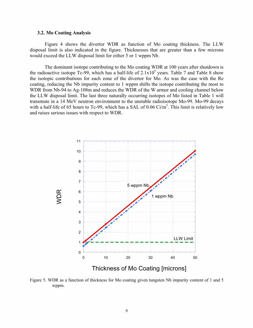
3.2. Mo Coating Analysis
Figure 4 shows the divertor WDR as function of Mo coating thickness. The LLW disposal limit is also indicated in the figure. Thicknesses that are greater than a few microns would exceed the LLW disposal limit for either 5 or 1 wppm Nb.
The dominant isotope contributing to the Mo coating WDR at 100 years after shutdown is
the radioactive isotope Tc-99, which has a half-life of 2.1x10⁵ years. Table 7 and Table 8 show the isotopic contributions for each zone of the divertor for Mo. As was the case with the Re coating, reducing the Nb impurity content to 1 wppm shifts the isotope contributing the most to WDR from Nb-94 to Ag-108m and reduces the WDR of the W armor and cooling channel below the LLW disposal limit. The last three naturally occurring isotopes of Mo listed in Table 1 will transmute in a 14 MeV neutron environment to the unstable radioisotope Mo-99. Mo-99 decays with a half-life of 65 hours to Tc-99, which has a SAL of 0.06 Ci/m3. This limit is relatively low and raises serious issues with respect to WDR.
0
1
2
3
4
5
6
7
8
9
10
11
0 10 20 30 40 5
WD
R
Thickness of Mo Coating [microns]
5 wppm Nb
1 wppm Nb
LLW Limit
0
Figure 5. WDR as a function of thickness for Mo coating given tungsten Nb impurity content of 1 and 5 wppm.
9

Table 7. Isotopic contribution to WDR of divertor for Mo coating, W armor, and cooling channel given 5 wppm Nb impurity in W at 100 years after shutdown. The total WDR values given in the table apply for all thicknesses one to 50 microns. To obtain WDR values in Figure 5, volume average the total WDR values.
Mo Coating & 5 wppm Nb
Waste Disposal Rating (WDR)
Isotope Coating W Armor Cooling Channel Re-186m -
(0%) 0.0332 (2.3%)
0.0147 (2.5%)
Nb-94 532 (8.1%)
0.617 (42.8%)
0.491 (53.8%)
Ag-108m - (0%)
0.569 (39.5%)
0.259 (28.4%)
Tc-99 5710 (86.6%)
0.206 (14.3%)
0.133 (14.6%)
Traces 0.003 (0.01%)
0.0148 (1.1%)
0.0143 (0.7%)
Total 6590
1.44
0.912
Table 8. Isotopic contribution to WDR of divertor for Mo coating, W armor, and cooling channel given 1 wppm Nb impurity in W at 100 years after shutdown. The total WDR values given in the table apply for all thicknesses one to 50 microns. To obtain WDR values in Figure 5, volume average the total WDR values.
Mo Coating & 1 wppm Nb
Waste Disposal Rating (WDR)
Isotope Coating W Armor Cooling Channel Re-186m -
(0%) 0.0332 (3.5%)
0.0147 (2.6%)
Nb-94 532 (8.1%)
0.138 (14.4%)
0.139 (24.8%)
Ag-108m - (0%)
0.569 (59.2%)
0.259 (46.2%)
Tc-99 5710 (86.6%)
0.206 (21.4%)
0.133 (23.8%)
Traces 0.003 (0.01%)
0.0148 (1.5%)
0.0143 (2.6%)
Total 6590
0.961
0.56
10

Table 9. Redistribution of isotopic compositions for tailored Mo coatings. Isotopes were removed from the natural element composition and percent abundances were redistributed.
Tailored (no Mo-100)
Tailored (no Mo-98,100)
Tailored (no Mo-94,98,100)
Mo-92 16.42% Mo-92 22.40% Mo-92 26.03% Mo-94 10.23% Mo-94 13.96% Mo-95 27.93% Mo-95 17.62% Mo-95 24.03% Mo-96 29.27% Mo-96 18.46% Mo-96 25.18% Mo-97 16.77% Mo-97 10.57% Mo-97 14.43% - - Mo-98 26.70% - - - -
It is possible to modify the Mo isotopic composition through isotopic tailoring. However, this process currently has unknown efficiency and cost. Analysis was performed by setting the various naturally occurring Mo isotopes to 100% abundance in the element definitions and performing WDR calculations. This allowed the determination of the isotopes of Mo that increase the likelihood of generating HLW. To examine the effect of isotopic tailoring, further calculations were made by completely removing the isotopes that produced large WDR and readjusting the remaining percent abundances of the other Mo isotopes.
Natural Mo consists of seven stable isotopes shown in Table 1. The heavier naturally occurring isotopes of Mo (97, 98, 100) will transmute into the radioactive isotope Tc-99 while Mo-94 transmutes into Nb-94 via the (n,p) reaction. Results indicate that Mo-94, Mo-98, and Mo-100 caused WDR greater than one in a volume-average of the total divertor. These were removed individually from natural Mo and percent compositions were redistributed accordingly. Table 9 indicates the distribution of percent compositions for the isotopically tailored Mo used in the WDR calculations.
Analysis was performed using a coating of 50 micron thick Mo and 5 wppm Nb impurity in the W. Assigning Mo to be 100% abundant in each of its isotopes indicates which individual stable isotopes contributes the largest to the divertor WDR. The results shown in Table 10 indicate that even with significant tailoring that involves up to 43% of Mo natural abundance, the divertor would not classify as LLW. It is clear that Mo-94, Mo-98, and Mo-100 contributed the largest to the WDR with values of 7, 14 and 50, respectively. Therefore, these isotopes were removed from Mo to reduce the WDR as shown in the three tailored cases in Table 9.
Since the divertor did not classify as LLW as a result of isotopic tailoring, the thickness of the coating was reduced to examine the allowable thickness of a tailored Mo coating. Figure 6 shows the effect on the divertor WDR when the coating thickness is varied from one to 50 microns for both 5 wppm and 1 wppm Nb impurity in W. For Nb impurity of 5 wppm, a coating of tailored Mo cannot exceed 8 microns to classify as LLW. Controlling the Nb to be 1 wppm allows greater thicknesses up to 25 microns.
11

Table 10. WDR for various Mo isotopic compositions at 100 years after shutdown given a 50 micron thick coating.
Mo Isotope WDR Main Isotopic Contributor to WDR Mo-nat 10.04 Tc-99 Mo-92 0.86 Nb-94 Mo-94 7.05 Nb-94 Mo-95 1.88 Nb-94 Mo-96 0.82 Nb-94 Mo-97 0.88 Tc-99 Mo-98 14.31 Tc-99 Mo-100 50.22 Tc-99
Tailored (no Mo-100) 5.84 Tc-99 Tailored (no Mo-98,100) 2.65 Nb-94
Tailored (no Mo-94,98,100) 1.93 Nb-94
0
0.5
1
1.5
2
0 10 20 30 40 5
WD
R
Thickness of Tailored Mo Coating [microns]
5 wppm Nb
1 wppm Nb
LLW Limit
0
Figure 6. WDR as function of tailored Mo coating thickness. The tailored Mo chosen for this was that with no Mo-94, Mo-98, and Mo-100.
12

0
8
16
24
32
40
48
56
64
72
80
0 10 20 30 40 5
WD
R
Thickness of Nb Coating [microns]
5 wppm Nb
1 wppm Nb
LLW Limit
0
Figure 7. WDR as a function of thickness for Nb coating given tungsten Nb impurity content of 1 and 5 wppm.
3.3. Nb Coating Analysis
Sandia National Labs did not propose the Nb coating, but analysis was performed to
illustrate the activation problems that Nb creates. Figure 7 shows the linearly increasing WDR as a function of Nb coating thickness. Thicknesses that are greater than a few microns would exceed the LLW disposal limit.
Clearly, controlling the Nb impurity in the W armor and cooling channel has no
significance since the coating is the major contributor to the compacted divertor WDR. By comparison, Nb generates much larger WDR than Re or Mo for similar thicknesses and Nb impurity (refer to Fig. 8). The lower SAL of 0.2 Ci/m3combined with Nb consisting of 100% Nb-93 result in the large activity of Nb-94 present and very high WDR that causes the Nb/W-based divertor to classify as HLW. Niobium-93 will transmute when bombarded with fusion neutrons to Nb-94 via the (n, gamma) reaction.
13

0
8
16
24
32
40
48
56
64
72
80
0 10 20 30 40 5
WD
R
Thickness of Coating [microns]
Nb
Mo
Re
0
Figure 8. WDR as a function of thickness for Re, Mo, and Nb coating given tungsten Nb impurity content
of 5 wppm.
Table 11. Isotopic contribution to WDR of divertor for Nb coating, W armor, and cooling channel given 5 wppm Nb impurity in W. The total WDR values given in the table apply for all thicknesses one to 50 microns. To obtain WDR values in Figure 8, volume average the total WDR values.
Nb Coating & 5 wppm Nb
Waste Disposal Rating (WDR)
Isotope Coating W Armor Cooling Channel Re-186m -
(0%) 0.0332 (2.3%)
0.0147 (2.5%)
Nb-94 52,870 (99.99%)
0.617 (42.8%)
0.491 (53.8%)
Ag-108m - (0%)
0.569 (39.5%)
0.259 (28.4%)
Tc-99 - (0%)
0.206 (14.3%)
0.133 (14.6%)
Traces 0.003 (0.01%)
0.0148 (1.1%)
0.0143 (0.7%)
Total 52,900
1.44
0.912
14

Table 12. Isotopic contribution to WDR of divertor for Nb coating, W armor, and cooling channel given 1 wppm Nb impurity in W. The total WDR values given in the table apply for all thicknesses one to 50 microns. To obtain WDR values in Figure 8, volume average the total WDR values.
Nb Coating & 1 wppm Nb
Waste Disposal Rating (WDR)
Isotope Coating W Armor Cooling Channel Re-186m -
(0%) 0.0332 (3.5%)
0.0147 (2.6%)
Nb-94 52,870 (99.99%)
0.138 (14.4%)
0.139 (24.8%)
Ag-108m - (0%)
0.569 (59.2%)
0.259 (46.2%)
Tc-99 - (0%)
0.206 (21.4%)
0.133 (23.8%)
Traces 0.003 (0.01%)
0.0148 (1.5%)
0.0143 (2.6%)
Total 52,900
0.961
0.56
4. Conclusions
This report analyzed the activation of thin coatings of Re and Mo placed on the ARIES-ACT W-based divertor to examine the effect of coating on the divertor WDR. A divertor without Re (or Mo) coating barely qualifies as LLW. Our results indicate that Re coatings must be limited to 30 microns in order for the Re/W-based divertor to classify as LLW. Controlling the Nb impurity below 4 wppm in the W armor and cooling channel increases the margin below the LLW disposal limit and allows for Re thicknesses larger than 50 microns.
Only a few microns of Mo coatings on the divertor cause WDR values to exceed the
LLW limit. Tailoring the Mo to remove ~43% of its isotopes (Mo-94, Mo-98, and Mo-100) reduced the WDR considerably, allowing Mo thicknesses larger than a few microns. To classify the Mo/W-based divertor as LLW, a thickness of 8 microns Mo would be allowed with Nb impurity of 5 wppm in W or 25 microns Mo with Nb impurity of 1 wppm in W.
In summary, the use of Re as in a thin surface layer to improve the W armor properties
does not appear to raise geological disposal concerns for plasma facing components. On the other hand, the use of Mo coating should be avoided because of potential high level-waste generation. Isotopic tailoring helps alleviate the waste disposal problem, but currently this process has unknown efficiency and cost. For these reasons, SNL could focus their effort on the further development of Re dentrite coating while Mo experiments would be regarded as a comparative study only.
15

Appendix The tables presented in this appendix show the negligible effect that the 10 micron W layer has on the volume-averaged divertor WDR. It is clear that due to the small thickness and low WDR of the front W layer, the contribution to the divertor WDR is insignificant and the WDR values with and without the 10 micron W layer are the same. Table 13. Divertor WDR values for 50 microns of Re and Mo. There tables show that the WDR values for a divertor with and without the 10 micron front W layer are the same.
16

17
References
1. L. El-Guebaly, V. Massaut, K. Tobita and L. Cadwallader, “Goals, Challenges, and Successes of Managing Fusion Active Materials,” Fusion Engineering and Design 83, Issues 7-9 (2008) 928-935.
2. The ARIES Project: http://aries.ucsd.edu/ARIES/. 3. X. Wang, S. Malang and M. Tillack, “High Performance Target Concept for a Power
Plant: a Combination of Plate and Finger Concepts,” Fusion Science and Technology 60, No. 1 (2011) 218-222.
4. L. El-Guebaly, R. Kurtz, M. Rieth, H. Kurishita and A. Robinson, “W-Based Alloys for Advanced Divertor Designs: Options and Environmental Impact of State-of-the-Art Alloys,” Fusion Science and Technology 60, No. 1 (2011) 185-189.
5. A. Robinson, L. El-Guebaly and D. Henderson, “W Based Alloys for Advanced Divertor Designs: Detailed Activation and Radiation Damage Analysis,” University of Wisconsin Fusion Technology Institute Report UWFDM-1378 (2010). Available at: http://fti.neep.wisc.edu/pdf/fdm1378.pdf.
6. Nuclear Regulatory Commission, 10CFR61, “Licensing Requirements for Land Disposal of Radioactive Waste,” Federal Register FR47 (1982) 57446.
7. S. Fetter, E. T. Cheng and F. M. Mann, “Long Term Radioactive Waste from Fusion Reactors: Part II,” Fusion Engineering and Design 13 (1990) 239-246.
8. T. J. Renk, B. Williams, L. El-Guebaly and A. Jaber, “Three Dimensional ‘Textured’ Coatings as First Wall Materials: Exposure to Energetic Ions on RHEPP-1,” Fusion Science and Technology 60, No. 2 (2011) 570-578.
9. R. Alcouffe et al., “DANTSYS: A Diffusion Accelerated Neutral Particle Transport Code System,” Los Alamos National Laboratory Report, LA-12969-M (1995).
10. P. Wilson and D. Henderson, “ALARA: Analytic and Laplacian Adaptive Radioactivity Analysis: A Complete Package for Analysis of Induced Activation – Volume I,” University of Wisconsin-Madison Fusion Technology Institute Report, UWFDM-1070 (1998). Available at: http://fti.neep.wisc.edu/pdf/fdm1070.pdf.
11. P. Wilson and D. Henderson, “ALARA: Analytic and Laplacian Adaptive Radioactivity Analysis: A Complete Package for Analysis of Induced Activation – Volume II,” University of Wisconsin-Madison Fusion Technology Institute Report, UWFDM-1071 (1998). Available at: http://fti.neep.wisc.edu/pdf/fdm1071.pdf.
12. D.L. Aldama, A. Trkov, “FENDL-2.1 Update of an Evaluated Nuclear Data Library for Fusion Applications,” International Atomic Agency Report INDC(NDC)-467 (2004).
13. A. Pashchenko, H. Wienke, J. Kopecky, J. Sublet and R. Forrest, “FENDL/A-2.0, Nuclear Activation Cross Section Data Library for Fusion Applications,” International Atomic Energy Agency Report IAEA-NDS-173 (1998).