fusionbasedapproachforautomaticlunar … ... ellipse fitting procedures basically involves...
TRANSCRIPT
Acta Futura 5 (2012) 163-172DOI: 10.2420/AF05.2012.163
ActaFutura
Fusion Based Approach For Automatic Lunar-Crater DetectionR.S. K*, A. L, K. V. S. S.
Department of Information Science and Technology, Anna University, Chennai - 600025. India
Abstract. is work presents lunar crater extrac-tion based on texture computation on fused im-ages. Texture is utilized as the key parameter toidentify the crater Candidate Area (CA). resh-olding of variance and homogeneity derived fromGray Level Co-occurrence Matrix (GLCM) thatis of industrial standard is used. e highlight andshadow present in the crater is used as the key fea-ture to identify the crater edge. Region growing isperformed with appropriate ”seed pixel”. Using thestatistical theory, the edge of the region grown area,is utilised to fit the ellipse around the crater. eexperiment is performed on individual images oflunar dataset as well as on fused images. Results in-dicate that the crater detection algorithm performsbetter when high spatial resolution image is usedwith low spatial resolution. It is seen that with im-age fusion, detection rate is significantly improvedfrom 71.09% to 92.48% between high spatial res-olution and fused image.
1 Introduction
History of geological processes of moon can be inter-preted by number of features such as Craters, rillesand ridges [30]. Impact craters, formed by collision ofcomets and asteroids on planetary surface, are essentialsource of information about the planetary geology andtheir surface characteristics. Age of a planetary body is
*Corresponding author. E-mail: [email protected]
directly related to the density of the craters and the evo-lution of terrain can be easily interpreted [13]. Duringthe initial Lunar and Mars exploratory missions, man-ual counting of crater was performed. But as the num-ber of missions increased, the technology of the missiontoo drastically increased resulting in very high spatialresolution images with large number of database. isrequired hefty amount of man power to perform thistask. In order to overcome these encumbrances, semiand fully automated crater extraction algorithm came toexistence. ese algorithms were bound to huge amountof limitation based on the planetary bodies themselvesand due to other factors. Planetary image, particularlylunar images, reveals low contrast and poor illuminationimages which eventually hides the features within them.Besides, crater extraction mainly dependent on the sunillumination angle and location of the feature on themoon. As the sun illumination angle becomes very low,the highlights and shadows which are the properties oflunar craters, tends to change highly and also illumi-nation diminishes and becomes very poor as the imagesmoves from equator to the poles. In addition, lunar sur-face itself is an undulating terrain with the features hid-den within them. us Craters Detection Algorithms(CDA) worked only for a particular test site and cannotbe generalised. Hence algorithmswhichwere developedduring the early stages did not test on real time imagesand further which applied on lunar images, were testedunder good illuminated flat terrain conditions.
163
Acta Futura 5 (2012) / 163-172 R.S. Kumar et al.
T . Image data properties used in crater detectionCharacteristics Chandrayaan-#1 SeleneSensor Terrain Mapping Camera/ Hyperspec-
tral ImagerMultiband Imager - Selene
Spectral resolution None/ 64 bands Center wavelength at 0.415,0.75,0.9,0.95,1.0 mm
Spectral range 0.5 to 0.85 nm; 0.4 to 0.9 nm 10 to 50 nmSpatial resolution 5 m/pixel; 80m/pixel 20 m/pixelData type 10 bit 16 bitYear of acquisition November,2008 2009
2 Background ofe Study
Craters Detection Algorithms (CDA) can be classifiedinto supervised and unsupervised detection. Supervisedalgorithm initially demands the properties of the craterto be taught by an expert and machine learning con-cepts to train the algorithms, followed by classificationof the unseen data. Algorithms such as Artificial NeuralNetwork (ANN), template matching [2, 22, 3] fall un-der this category. But contradictorily, unsupervised al-gorithms namely Hough transform, Chord Mid-pointHough Transform (CMHT) [18], mathematical mor-phology and texture classifiers [29] tend to recognize thecraters patterns based on the geometric properties suchas shape and size etc. Feature extraction can be broadlyused for applications ranging from Guidance Naviga-tion Control (GNC) during the Entry Descent Land-ing (EDL) process, to estimate the age of the planetarysurface. is directly related to crater count and geolog-ical activities and search for unknown craters on Earth.Before applying any feature extraction, the images needto be preprocessed. First, the noise is smoothed by ap-plying a Gaussian filtering and a median filtering op-eration in cascade [27]. Craters counts are the onlyavailable tool for measuring the relative ages of geo-logic formations on planets. For example, the mostcomprehensive catalogs of craters on Mars contain in-formation on 19,308 craters [19], 42,283 craters [4],and 57,633 craters [20] respectively. ey contain onlycraters larger than 5 km in diameter. For the Moonthe most comprehensive catalogue [1] lists 8497 namedcraters that are larger than few kilometres in diameter,and for Mercury the most comprehensive catalogue [10]lists 6334 craters that are larger than 10 km in diameter.In addition, much smaller global datasets of large cratersexist [23] for some Galilean satellites of Jupiter; 232craters are catalogued on Ganymede, and 130 craters
are catalogued on Callisto. No comprehensive catalogueof smaller, sub-km craters exist for any planetary body.is is because building such a dataset is a very labo-rious process, ill-suited for visual detection but well-suited for an automated technique. In this paper wepresent a different approach to auto-detection of cratersin high spatial resolution panchromatic planetary im-ages. Our focus is on surveys of sub-km craters becauselarger craters can be identified either manually [4, 21]or using a topography- based algorithm [25, 26]. Lunarimages containing craters will appear in different char-acteristics when conditions are different such as illumi-nation (solar elevation angle), local terrain condition ofcrater (the size and depth of crater) and shooting con-dition [7]. Image pixel arrays are rotated, translated orotherwise transformed to match piece of an image [14].Lunar features also exhibit different structures and vari-able sizes [8]. DEM based CDAs has become the keyinterest to research since craters which are hidden in vi-sual images can be visible in DEM. But the elevationdata are manipulated using interpolation rather than di-rect laser measurements and perhaps are smudgy in na-ture. Due to this craters which are visible in opticalimagery will not be clear in DEM [22]. In the pro-posed technique, a very high spatial resolution image hasbeen used and eventually a large number of very smallcraters will be visible ranging from (20 m to 400 m) areattempted to be detected by the proposed algorithm.Since CDAs involving exhaustive search in the imagewill result in higher computational time. erefore, wepropose a crater Candidate Area (CA) to detect a craterbased selection or rejection of the particular area that canidentify even the degraded craters. Supervised learningperforms well with cases where training and testing arecarried out under similar landforms. Instead, when thetesting is performed on a totally different image cap-tured under different solar illumination angle results in
164 DOI: 10.2420/AF05.2012.163
Fusion based approach for automatic lunar-crater detection
poor classification accuracy and tested to perform in lesscomputation [6]. Image fusion using wavelets have beenused in the last few years, to improve the spatial andspectral details of the image [12]. With several advance-ments in fusion, several modified versions of waveletswere proposed. Improved fusion technique by combin-ing a-trous and empirical mode decomposition has beenused to combine panchromatic and multispectral quick-bird images [24]. Wavelet has also been combined withother fusion techniques such as IHS and PCA [16, 31].In this paper, we aim to demonstrate the effectivenessof texture based feature extraction on fused images. Ini-tially, we test the algorithm on poor resolution imagesand extract the number of craters. Later, by combiningtwo images by fusion technique, we test the algorithmfor the extraction of craters.
3 Image Data Set
e image data used for testing the crater detection al-gorithm are from Chandrayaan-1, Indian moon mis-sion satellite and Selene of Japanese Moon mission. Im-ages are taken at high spatial resolution of 5m/ pixel and20m/pixels and at different types of terrain and illumi-nation conditions. e Table 1 lists the properties ofimage data used.
4 Methodology
e flow chart of the proposed methodology is shown inFig 1. Unlike terrestrial images, lunar images are com-posed of very less number of features and hence the tonalvariation (texture) is considered for feature extractionfrom lunar images.
4.1 Texture Computation
Texture is defined as the frequency of tonal variations,which is widely used in the feature extraction processes.In particular, spatial texture measures like Gray LevelCo-occurrence Matrix (GLCM), Gray Run LengthMatrix (GRLM) are of industrial standards due to theircomputationally less intensive nature. e GRLM isa method of extracting higher order statistical texturefeatures. A set of consecutive pixels with the same greylevel, collinear in a given direction constitute a grey levelrun. e run length is the number of pixels in the runand the run length value is the number of times sucha run occurs in an image. e Grey Run Length Ma-trix(GRLM) is a two-dimensional matrix in which each
element p(i, j/θ), gives the total number of occurrencesof runs of length j at grey level i, in a given directionθ. e θ can take four different directions (θ=0, 45, 90and 135 degrees). For example a 4X4 sub-image with4 different grey levels and its corresponding run-lengthmatrix p(i, j/θ = 0) is shown in the figure 2. A movingwindow, termed as kernel, is traversed through the inputimage where n=3,5,7,9. Here n is chosen as 3 with d=1and θ applied in all direction. Texture parameters suchas Variance and Homogeneity are computed in order toselect the Candidate Area (CA). Variance captures thesudden change in the pixel and Homogeneity measurethe maximum value at the similar area. Hence by se-lecting the appropriate threshold, these two images arethresholded.
4.2 Candidate Area processing
Older craters have rims faded out and hence the abovementioned technique captures only the inner areas insuch craters. Also, craters in which ejecta materialspresent, this CA selection technique captures the ex-cess area and these two conditions are depicted in Fig3 and Fig 5. In order to overcome this problem, thebox is expanded or shrinked based on the concept of re-gion growing on both the highlight and shadowed re-gion. Depending on the grown area, the CA is modifiedaccordingly. If there a sharp rise or a dip in the terrainthen it is captured as a CA, as per the above procedure.By using a particular threshold, false detection of cratersis overcome (4).
4.3 Region Growing
e highlight and shadow becomes the properties of thecrater, specifically for the images captured with low sunangles. is phase plays an important role in determin-ing the shape of the ellipse to be fitted. Region grow-ing, a image segmentation procedure, is a process ofgrouping similar pixels is performed till the differenceof image pixels to the seed pixel is less than thresholdwhich is depicted in Eqn. 1. |gs − gc| < threshold
(1) Since the input is the panchromatic image, max-imum and minimum pixel values are chosen as the seedpixels for the highlight and shadow respectively. Op-timized threshold value is chosen which is invariant ofthe input image capturing scenarios. After region grow-ing, canny edge is obtained for the region grown area.For clearer visualization, a single crater is chosen and itscorresponding region grown area and its edge image is
DOI: 10.2420/AF05.2012.163 165

Acta Futura 5 (2012) / 163-172 R.S. Kumar et al.
F . Methodology for crater detection using CDA algorithm
shown in Figure 6.
4.4 Ellipse fitting
Ellipse fitting procedures basically involves estimationof the variables in the parameter space such as HoughTransform (HT) and GA based techniques, which is atime consuming and a complex procedure. Hence a sta-tistical procedure is adopted, which is computationallysimple involving geometric variables of the craters to de-tects and fit the ellipse. is technique is chosen sincethe aim of the paper is to create a database of small andminute craters which hence involves a larger processingtime. Detailed description of the ellipse fitting proce-dure is described in [28, 15] is adopted in this paper.
5 Image Fusion
Image fusion is the process of combining informationfrom two or more images, to obtain complementary in-formation by a certain fusion rule [17]. ere has beenmany fusion techniques used in the past such as Inten-sity hue Saturation (IHS), Principal Component Anal-ysis (PCA), Brovey, Multiplicative and wavelet fusion.In this study, we aim to combine information from high
spatial resolution image and high spectral resolution im-age from different sensor. Here, we take image datasetfrom Hyperspectral Imager (HySI) of Chandrayaan-1and Multiband Imager (MI) of Selene. Compared toconventional fusion techniques, PCA combined waveletfusion method exhibits best spatial and spectral fidelityof the fused image [11]. Hence in our study, we demon-strate the effectiveness of feature extraction algorithmusing the fused image of PCA combined wavelet.
5.1 Traditional Principal Component Analysis
Principal Component Analysis is a mathematical andorthogonal transformation that converts the linear datainto a new coordinate data exhibiting maximum vari-ance, along first principal component, second principalcomponent and so on [9]. is transformation is alsocalled as Karhunen-Loéve (KL) transformation since ittransforms the set of correlated variables into uncorre-lated variables. e method of fusion using PCA in-volves the first principal component of the low spatialresolution image to be combined with high spatial reso-lution image. In fusion, we consider only the first prin-cipal component of low spatial resolution image sincethe first PC image contains almost 98% of the total im-
166 DOI: 10.2420/AF05.2012.163

Fusion based approach for automatic lunar-crater detection
T . Statistics of crater detecton in images captured under two different illumination and terrain conditionsImages Craters Detected Not det. False det. Det. rate False det. rate
Chandrayaan - TMC 1 (8a) 384 358 31 5 93.23% 1.39%Chandrayaan - TMC 2 (8b) 320 293 35 8 91.56% 3.04%
Chandrayaan - TMC 3 245 222 29 6 90.61% 2.70%Chandrayaan - TMC 4 12 10 3 1 83.33% 10.00%Chandrayaan - TMC 5 14 11 4 1 78.57% 9.09%
Selene - MVA 1 30 24 8 2 80% 8.33%Selene - MVA 2 193 185 10 2 95.85% 1.08%
F . Sub-image and its run-length matrix p(i, j/θ = 0)
age data. is method of fusion is believed to eliminatedata redundancy and preserve much spectral informa-tion [5].
5.2 Wavelet image fusion
Wavelet is a frequency domain operation that decom-poses the image into detailed and approximate compo-nents at level 2j. e approximate coefficient is pro-duced at level j+1, also called low frequency componentand detailed coefficients along horizontal, vertical anddiagonal. e approximate component contains muchinformation and it is used for fusion while the detailedcomponents contain much of noise and less informa-tion. Wavelet decomposition is performed by passingthe input images using low and high pass filter and the
F . Enlarging the CA to its edges
F . Results of crater detection after CA rejection
rows of the image are decimated by a factor of 2. Again,the two outputs are passed through the low and highpass filter and the columns of the image are decimatedby factor 2. Reconstruction of discrete wavelet trans-form (DWT) is performed by passing the columns ofthe wavelet coefficients to be interpolated by a factorof 2. e high frequency component is passed throughthe low pass filter and low and diagonal components arepassed through high pass filter. e components areagain added by interpolating along the rows using theappropriate filter to obtain the fused image.
5.3 PCA combined wavelet fusion
is technique combines fusion techniques of PrincipalComponent analysis and wavelet to obtain fused im-age that has greater details of spatial and spectral in-formation content. e methodology for PCA com-bined wavelet fusion is as follows and illustration of themethod used is seen in Figure 7.
DOI: 10.2420/AF05.2012.163 167

Acta Futura 5 (2012) / 163-172 R.S. Kumar et al.
F . Shrinking the CA to delete the excess area
F . Highlighting and Shadow detection followed by regiongrowing
1. Two input images high spatial resolution imageHR (MI of Selene) and high spectral resolutionimageXS (HySI of Chandrayaan-1) are consideredfor image fusion.
2. For high spectral resolution image XS, principalcomponent analysis is performed as stated in sec-tion 5.1. e First principal component of XS (ie.,PC1) is considered since it is said to contain max-imum amount of information representing the en-tire image data.
3. e high spatial resolution image HR and the firstprincipal component PC1 is decomposed usingdiscrete wavelet transform into two sets of one ap-proximate components and three detailed compo-nents (Lσ, LHσ, HLσ and Hσ from HR and Li,LHi, HLi and Hi from PC1).
4. e low frequency component Lσ and Li are fusedand detailed coefficients from high spatial resolu-tion image (LHσ, HLσ and Hσ) are used dur-ing wavelet reconstruction or inverse wavelet trans-forms.
5. is gives a new fused produced P and to obtainoriginal image it is essential to perform inversePCA. us, the fused image will have spatial reso-lution as that of HS and spectral resolution (num-ber of spectral bands) as that of XS.
6 Results And Discussion
e ultimate aim of this paper is to prepare a database ofvery small craters which demands a greater man powerif performed manually. e study areas chosen to testthis algorithm were taken under totally different illumi-nation conditions with different terrain conditions andillumination angles, which is very important for the val-idation of the performance of the algorithm. Hence bythis methodology, craters with pixels greater than 4 pix-els in diameter and with the maximum size of 100 pix-els can be captured using this methodology. It can beseen from Fig 8(a), that many craters are left out, whichare omitted during the rejection phase. is is becausea sudden rise and a fall might be captured as crater inCA identification process. Hence CA which doesn’tsatisfy the threshold conditions in both highlight andshadow are rejected. erefore, this algorithm is craftedin such a way to detect craters with less false detectionrate rather than having higher detection rate with highfalse detection. Total number of craters present in animage is counted manually since there was no databaseavailable at this resolution to validate the results. Ta-ble 2 tabulates the statistics of crater detection in whicheven though the two images portrayed in the figure 8(a)and (b) are totally different, the detection rate shownin table 2 is constant which is greater than 90% withvery less false detection rate around 2%. Images cap-tured from Selene MI- MVA are also tested to verifythe performance at different image resolution too. It isseen that images with number of craters less than 30,has detection rate which is around 80%. is mightbe due to less variance to distinguish between features(highlights and shadows) in the image. As stated, falsedetection rate is kept very low in all the images, whichis also the reasons for less detection rate in image withcraters less than 30. Besides, since the total number ofcraters is very low, a less false detection decreases thedetection rate. Hence his method performs very wellfor images with crater greater than 200. e thresh-olds selected in the rejection phase are obtained usingthe trial and error technique. When applied to differentimage, they are found to be values which yielded maxi-mum detection rate. Even thought the algorithm is de-signed in avoid false detection, an average of 2% arisesin all the scenarios. is might be due to the reasonthat reduced quantisation of the GLCM computation.GLCM is computed on the image which is reducedfrom 11 bit to 6 bit in order to perform faster compu-tation. is might have resulted some information loss.
168 DOI: 10.2420/AF05.2012.163

Fusion based approach for automatic lunar-crater detection
F . Methodology for image fusion using PCA combined wavelet transforms
F . Crater detection in the Chandrayaan TMC image captured under two different illumination and terrain conditions
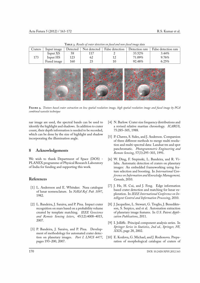
Further, crater detection algorithm as proposed in Sec-tion 4, is implemented individually on low spatial reso-lution image (80m/pixel), high spatial resolution image(63m/pixel) and on the fused image using PCA com-bined wavelet fusion. is fusion was chosen based onthe literature [11] and since this fusion technique gavegreater spatial and spectral correlation coefficient. Fur-ther, the fused image is given to Principle ComponentAnalysis (PCA) to extract information from multi-bandand to convert multi-spectral image into a single band.Results indicate number of craters detected in the origi-nal high spatial resolution image is less when comparedto the crater detection algorithm applied on the fusedimage. is might be due to the reason that the fusedimage has both the spatial and spectral content (9). Inthis experiment, the low spatial resolution image from
Chandrayaan-1 (HySI) is rich in spectral information,as it contains 64 spectral bands. But, the problem withthe image is that it lacks spatial details or clarity. us,to combine the spatial details into Chandrayaan-1, weperform image fusion with Selene that has better spa-tial resolution. Finally, the fused image will poses thesensor attributes of Chandrayaan-1 and Selene. Fromthe results, the detection rate is improved from 71.09%to 92.48% with image fusion and false detection rate isvery low (3).
7 FutureWork
Highlight and shadow are obtained as the maximumand minimum pixel value in the image which is an as-sumption at some point. Hence when multi spectral lu-
DOI: 10.2420/AF05.2012.163 169
Acta Futura 5 (2012) / 163-172 R.S. Kumar et al.
T . Results of crater detection on fused and non-fused image dataCraters Input image Detected Not detected False detection Detection rate False detection rate
Input XS 58 117 2 33.52% 3.44%173 Input HS 123 62 12 71.09% 9.76%
Fused image 160 23 10 92.48% 6.25%
F . Texture based crater extraction on low spatial resolution image, high spatial resolution image and fused image by PCAcombined wavelet technique
nar image are used, the spectral bands can be used toidentify the highlight and shadows. In addition to cratercount, their depth information is needed to be recorded,which can be done by the size of highlight and shadowincorporating the illumination angle.
8 Acknowledgements
We wish to thank Department of Space (DOS) -PLANEX programme of Physical Research Laboratoryof India for funding and supporting this work.
References
[1] L. Andersson and E. Whitaker. Nasa catalogueof lunar nomenclature. In NASA Ref. Pub. 1097,1982.
[2] L. Bandeira, J. Saraiva, and P. Pina. Impact craterrecognition on mars based on a probability volumecreated by template matching. IEEE Geoscienceand Remote Sensing letters, 45(12):4008–4015,2007.
[3] P. Bandeira, J. Saraiva, and P. Pina. Develop-ment of methodology for automated crater detec-tion on planetary images. Part I. LNCS 4477,pages 193–200, 2007.
[4] N. Barlow. Crater size frequency distributions anda revised relative martian chronology. ICARUS,75:285–305, 1988.
[5] P. Chavez, S. Sides, and J. Anderson. Comparsionof three different methods to merge multi resolu-tion and multi-spectral data: Landsat tm and spotpanchromatic. Photogrammetric Engineering andRemote Sensing, 57(3):295–303, 1991.
[6] W. Ding, F. Stepinski, L. Bandeira, and R. Vi-lalta. Automatic detection of craters on planetaryimages: An embedded frameworking using fea-ture selection and boosting. In International Con-ference on Information and KnowledgeManagement,Canada, 2010.
[7] J. He, H. Cui, and J. Feng. Edge informationbased crater detection and matching for lunar ex-ploration. In IEEE International Conference on In-telligent Control and Information Processing, 2010.
[8] J. Jacqueline, L. Stewart, G. Troglio, J. Benedikts-son, S. Serpico, and et al. Automation extractionof planetary image features. In U.S. Patent Appli-cation Publications, 2011.
[9] I. Jolliffe. Principal component analysis series. InSpringer Series in Statistics, 2nd ed., Springer, NY,XXIX, page 28, 2002.
[10] E. Kozlova, G. Michael, and J. Rodionova. Prepa-ration of morphological catalogue of craters of
170 DOI: 10.2420/AF05.2012.163

Fusion based approach for automatic lunar-crater detection
mercury. In Lunar and Planetary Science Confer-ence XXXII, pages 96–97, 2000.
[11] A. Lavanya, K. Vani, S. Sanjeevi, and R. Kumar.Image fusion of the multi-sensor lunar image datausing wavelet combined transformation. In RecentTrends in Information Technology (ICRTIT), 2011International Conference on, pages 920–925. IEEE,2011.
[12] H. Li, B. Manjunath, and S. Mitra. Multisensorimage fusion using the wavelet transform. Jour-nal of GraphicalModels and Image Processing, 57(3),1995.
[13] R. Martins, P. Pina, S. Marques, and M. Sil-veria. Crater detection by a boosting ap-proach. IEEEGeoscience andRemote Sensing letters,6(1):127–131, 2009.
[14] D. Meng, C. Yun-feng, and W. Qing-xian. Au-tonomous craters detection from planetary image.In e 3rd International IEEE Conference on Inno-vative Computing Information and Control, 2008.
[15] D. Meng, C. Yunfeng, and W. Qingxian.Method of passive image based crater au-tonomous detection. Chinese Journal of Aeronautics,22(3):301–306, 2009.
[16] M. Metwalli, A. Nasr, O. Farag Allah, and S. El-Rabaie. Image fusion based on principal compo-nent analysis and high-pass filter. InComputer En-gineering & Systems, 2009. ICCES 2009. Interna-tional Conference on, pages 63–70. IEEE, 2009.
[17] V. Pohl. Multisensor image fusion in remote sens-ing: concepts, methods and applications. Inter-national Journal of Remote Sensing, 19(5):823–854,1998.
[18] W. Qu. Chord midpoint hough transform basedellipse detection method. Journal of Zhejiang Uni-versity (Engineering Science), 39(8):1132–1135,2005.
[19] J. Rodionova, A. Karlov, T. Skobeleva, and et al.Morphological catalogue of the craters of themoon. In Editor V.V. Shevchenko. JAXA publica-tions, 2000.
[20] G. Salamunicar, S. Loncaric, P. Pina, L. Ban-deira, and J. Saraiv. Ma130301gt catalogue of
martian impact craters and advanced evaluation ofcrater detection algorithms using diverse topogra-phy and image datasets. Planetary and Space Sci-ence, 59:111–131, 2011.
[21] G. Salamuniccar and S. Loncaric. Gt-57633 cata-logue of martian impact craters developed for eval-uation of crater detection algorithms. Planetaryand Space Science, 56(15):1992–2008, 2008.
[22] G. Salamuniccar and S. Loncaric. Method forcrater detection from martian digital topogra-phy data using gradient value/orientation, mor-phometry, vote analysis, slip tuning, and calibra-tion. IEEE Geoscience and Remote Sensing letters,48(5):2317–2329, 2010.
[23] P. Schenk, C. Chapman, K. Zahnle, and J. Moore.Age and interiors: the cratering record of thegalilean satellites. In Jupiter: e Planet, Satellitesand Magnetosphere, pages 427–456, 2004.
[24] C. Shao-hui, S. Hongbo, Z. Renhua, and T. Jing.Fusing remote sensing images using à trouswavelet transform and empirical mode decompo-sition. Pattern Recognition Letters, 29:330–342,2007.
[25] T. Stepinski, M. Mendenhall, and B. Bue. Ro-bust automated identification of martian impactcraters. In Lunar and Planetary Science XXXVIII(CD-ROM), no. 1202. Lunar and Planetary Insti-tute, 2007.
[26] T. Stepinski and E. Urbach. Raster maps of cratersdepths in southern hemisphere of mars: potentialproxy for spatial distribution of ground ice. In Lu-nar and Planetary Science XXXIX (CD-ROM), no.1272. Lunar and Planetary Institute., 2008.
[27] G. Troglio, S. Serpico, and J. Moigne. Automaticextraction of planetary image feature. In irdIEEE International Conference on Space MissionChallenges for Information Technology ’09, 2009.
[28] E. Urbach, B. Jos, and M. Wilkinson. Connectedshape-size pattern spectra for rotation and scale-invariant classification of gray-scale images. IEEETransactions on Pattern Analysis AndMachine Intel-ligence, 29(2):272–285, 2007.
[29] R. Urbach and F. Stepinski. Automatic detec-tion of sub-km craters in high resolution planetary
DOI: 10.2420/AF05.2012.163 171

Acta Futura 5 (2012) / 163-172 R.S. Kumar et al.
images. Planetary and Space Science, 57:880–887,2009.
[30] T. Vinogradova, M. Burl, and E. Mjolsness.Training of a crater detection algorithm for marsimagery. In Proc. IEEE Aerospace conference, 2002.
[31] Y. Zhang and G. Hong. An ihs and wavelet inte-grated approach to improve pan-sharpening visualquality of natural colour ikonos and quickbird im-ages. Information Fusion, 6(3):225–234, 1995.
172 DOI: 10.2420/AF05.2012.163