future naval concepts — crew reductions through … · through improved damage control...
TRANSCRIPT

Naval Research LaboratoryWashington, DC 20375-5320
NRL/MR/6180--07-9025
Future Naval Concepts — Crew Reductionsthrough Improved Damage ControlCommunications (FNC-CRIDCC)Triad Test 2 Report (18-22 Sep 2006)
January 12, 2007
Approved for public release; distribution is unlimited.
Thomas T. sTreeT and Frederick W. Williams
Navy Technology Center for Safety and SurvivabilityChemistry Division
david shoWalTer and sTephen Zak
L. Robert Kimball and Associates, Inc.Pittsburgh, Pennsylvania
l. scoTT cooper kenneTh e. halloWay iiimichael rininger
charles miller
MTS Technologies, Inc.Virginia Beach, Virginia, and Johnstown, Pennsylvania
Bradley shirley
samuel genovese
rendell perry
kenney mccomBs

i
REPORT DOCUMENTATION PAGE Form ApprovedOMB No. 0704-0188
3. DATES COVERED (From - To)
Standard Form 298 (Rev. 8-98)Prescribed by ANSI Std. Z39.18
Public reporting burden for this collection of information is estimated to average 1 hour per response, including the time for reviewing instructions, searching existing data sources, gathering and maintaining the data needed, and completing and reviewing this collection of information. Send comments regarding this burden estimate or any other aspect of this collection of information, including suggestions for reducing this burden to Department of Defense, Washington Headquarters Services, Directorate for Information Operations and Reports (0704-0188), 1215 Jefferson Davis Highway, Suite 1204, Arlington, VA 22202-4302. Respondents should be aware that notwithstanding any other provision of law, no person shall be subject to any penalty for failing to comply with a collection of information if it does not display a currently valid OMB control number. PLEASE DO NOT RETURN YOUR FORM TO THE ABOVE ADDRESS.
5a. CONTRACT NUMBER
5b. GRANT NUMBER
5c. PROGRAM ELEMENT NUMBER
5d. PROJECT NUMBER
5e. TASK NUMBER
5f. WORK UNIT NUMBER
2. REPORT TYPE1. REPORT DATE (DD-MM-YYYY)
4. TITLE AND SUBTITLE
6. AUTHOR(S)
8. PERFORMING ORGANIZATION REPORT NUMBER
7. PERFORMING ORGANIZATION NAME(S) AND ADDRESS(ES)
10. SPONSOR / MONITOR’S ACRONYM(S)9. SPONSORING / MONITORING AGENCY NAME(S) AND ADDRESS(ES)
11. SPONSOR / MONITOR’S REPORT NUMBER(S)
12. DISTRIBUTION / AVAILABILITY STATEMENT
13. SUPPLEMENTARY NOTES
14. ABSTRACT
15. SUBJECT TERMS
16. SECURITY CLASSIFICATION OF:
a. REPORT
19a. NAME OF RESPONSIBLE PERSON
19b. TELEPHONE NUMBER (include areacode)
b. ABSTRACT c. THIS PAGE
18. NUMBEROF PAGES
17. LIMITATIONOF ABSTRACT
Future Naval Concepts — Crew Reductions through Improved Damage ControlCommunications (FNC-CRIDCC)Triad Test 2 Report (18-22 Sep 2006)
Thomas T. Street, Frederick W. Williams, L. Scott Cooper,* Kenneth E. Halloway III,* Michael Rininger,* Charles Miller,* Bradley Shirley,* Samuel Genovese,* Rendell Perry,* Kenney McCombs,* David Showalter,† and Stephen Zak†
Naval Research Laboratory, Code 61804555 Overlook Avenue, SWWashington, DC 20375-5320
NRL/MR/6180--07-9025
Approved for public release; distribution is unlimited.
Unclassified Unclassified UnclassifiedUL 70
Thomas T. Street
(202) 767-2254
Damage controlWLAN
The object of Triad Test 2 was to conduct and document an RF coverage survey of the installed WLAN aboard ex-USS Shadwell in a benign environment, obtain RF WLA data during fire events, and evaluate the ability of the communications equipment to continue to provide a communication capability. The fire events were used to determine the ability of the equipment to provide voice and data communications over Voice over Internet Protocol (VoIP) and Power Line Communication (PLC) paths during actual fire and smoke environments. The intelligibility of the information communicated was subjectively and objectively determined using ANSI intelligibility standards.
12-01-2007 Memorandum Report
Office of Naval ResearchOne Liberty Center875 North Randolph Street, Suite 1425Arlington, VA 22203
18 - 22 September 2006
*MTS Technologies, Inc., Virginia Beach, VA, and Johnstown, PA†L. Robert Kimball and Associates, Inc., Pittsburgh, PA
N00014-05-C-0332
61-8513-0-6-5
Voice over Internet Protocol (VoIP)Power Line Communications (PLC)
Intelligibility standardsWireless communications

CONTENTS INTRODUCTION ........................................................................................................................ 1 SETUP AND INSTALLATION................................................................................................... 2 SELF CONTAINED BREATHING APPARATUS (SCBA) ......................................................2 WIRELESS LOCAL AREA NETWORK (WLAN) INFRASTRUCTURE................................3 SOFTPHONE EVALUATION ....................................................................................................3 THREE-WAY CONFERENCE CALL TESTING ......................................................................3 Wireless to Wired VoIP Conference Call................................................................................3 Wireless-to-Wireless VoIP Conference Call ...........................................................................4 Wireless Sound Powered Phone (SPP) Circuit Conference Call.............................................4 POWER LINE COMMUNICATIONS (PLC) TESTING............................................................4 PLC Installation and Verification ............................................................................................4 PLC Standalone Network Testing ...........................................................................................5 Voice Calls on the PLC Standalone Network..........................................................................6 SPP TESTING ..............................................................................................................................7 SPP Testing and Verification...................................................................................................7 SPP Communications Case to Communications Case Untethered Testing.............................8 WLAN 802.11G SURVEY...........................................................................................................8 THROUGHPUT TESTING METHODOLOGY..........................................................................9 COMMUNICATIONS TEST 1 – NON-FIRE AND SMOKE CONDITIONS`..........................9 COMMUNICATIONS TEST 1 OBSERVATIONS/CONCLUSIONS .......................................10 FIRE EVENT 1.............................................................................................................................12 Fire Event 1 Overview.............................................................................................................12 Fire Event 1 Tests and Activities .............................................................................................14 Fire Event 1 Observations/Conclusions...................................................................................18
iii

FIRE EVENT 2.............................................................................................................................19 Fire Event 2 Overview.............................................................................................................19 Fire Event 2 Tests and Activities .............................................................................................21 Fire Event 2 Observations/Conclusions...................................................................................24 FIRE EVENT 3.............................................................................................................................25 Fire Event 3 Overview.............................................................................................................25 Fire Event 3 Tests and Activities .............................................................................................27 Fire Event 3 Observations/Conclusions...................................................................................30 SUMMARY OF CONCLUSIONS AND RECOMMENDATIONS ...........................................32 Conclusions..............................................................................................................................32 Recommendations....................................................................................................................32 REFERENCES .............................................................................................................................33 APPENDIX A...............................................................................................................................A-1 APPENDIX B ...............................................................................................................................B-1 APPENDIX C ...............................................................................................................................C-1 APPENDIX D...............................................................................................................................D-1
iv

FUTURE NAVAL CONCEPTS-CREW REDUCTIONS THROUGH IMPROVED DAMAGE CONTROL COMMUNICATIONS (FNC-CRIDCC)
TRIAD TEST 2 REPORT (18-22 SEP 2006)
INTRODUCTION Ships of the future will require vast, state-of-the-art, survivable communications networks capable of integrating a multitude of communications architectures with numerous communications sources and technologies. In order to maintain an operational damage control (DC) communications capability during ship conflagrations and DC operations, a communication system must be diverse and have the capability of operationally monitoring communications capabilities and re-routing communications by automatically switching from the failed paths/technologies to ones that are still operational. Using a combination of wired and wireless technologies could allow damaged areas of the ship to communicate using one technology and the rest of the ship to use another technology. The DC Triad concept [1],[2],[3],[4] will provide data and voice using a combination of wireless LAN’s and communication over a ships power grid and as a fallback option will provide a wireless voice link into a ship’s sound powered phone circuits. Previous radio frequency (RF) communications system development and testing in condition ZEBRA environments onboard the ex-USS SHADWELL [5] has determined the effectiveness of wireless LAN’s used for communications in that environment [6],[7],[8]. In addition, several public utility companies have installed, tested and are using equipment that delivers low cost DSL internet connections to their customers, over their power lines [9]. The successful power line delivery of internet connections and the wireless development on ex-USS SHADWELL indicate that a state-of-the-art communication system using these technologies is possible for shipboard use. Three data delivery approaches are employed to provide the capability for a survivable DC communications system. The three communications technologies are; (a) wireless local area networks (LAN), (b) power line communications and (c) a wireless input to the sound powered phone system. This effort has been designated Damage Control Operational Concepts Phase II.
MTS Technologies, Inc., under contract to the Office of Naval Research (ONR) is developing a conceptual prototype DC communications capability. The objective of the prototype is to provide a redundant, reconfigurable, recoverable, compatible (backward and forward) communications capability complementing and enhancing current DC capabilities. Commercially available equipment and capabilities have been acquired to implement a DC Triad prototype. The prototype includes; (a) wireless voice and data transmission over Wireless Local Area Network (WLAN) using Voice/Data over Internet Protocol (VoIP), (b) voice and data transmission over shipboard power lines (Power Line Communications - PLC) and (c) voice over Sound-Powered Phone (SPP) lines. The prototype is based on the “triad” communications concept discussed above, which at its core has a wireless communications interface between a DC decision-maker at the scene of an event and the DC command and control node. This program implementation expands research completed during Phase II of the Damage Control Operational Concepts (DCOC) Program, conducted in FY05 and documents the demonstration of the DC Triad prototype on ex-USS SHADWELL on September 18 – 22, 2006 [2].
1
_______________Manuscript approved December 4, 2006

The following activities were performed on the September 18-22 2006 trip to the ex-USS Shadwell:
• Conducted an RF survey (mapping) of the installed WLAN aboard ex-USS Shadwell (LSD 15) in a benign environment
• Obtained RF WLAN (Wireless LAN) data during Fire Events
• Evaluated the ability of the equipment [10],[11],[12],[13]to provide voice and data communications over the VoIP and PLC paths of the DC Communications Triad and voice communications over the ship’s installed SPP system from pre-determined compartments aboard ex-USS Shadwell during actual fire and smoke conditions
• Subjectively determined the intelligibility of the information transmitted in accordance with ANSI intelligibility standards [14],[15].
• Objectively determined the intelligibility of data transmitted over two of the three paths of the DC Communications Triad.
SETUP AND INSTALLATION
The following Triad components were installed on the 02 Level to allow for VoIP phone calls, Vocera® badge operation, and text messaging capabilities:
• Zultys® MX-250 VoIP Server
• Zultys® BPS-12 Backup Power Supply for the MX-250
• Dell® Poweredge1800 Server with Monitor, keyboard, and mouse
• APC® Backup Power Supply for the Poweredge 1800
These components were connected to the ex-USS Shadwell LAN and verified for connectivity and functionality. SELF CONTAINED BREATHING APPARATUS (SCBA) The team discussed potential Triad hardware (microphone and speaker) constraints with regard to the SCBA mask, straps, and “Loudmouth” voice amplifier. The goal was to try to determine what types of microphones, headsets, and ear bud speakers would be the most ergonomically feasible devices to use while wearing a SCBA.
2

WIRELESS LOCAL AREA NETWORK (WLAN) INFRASTRUCTURE It was determined during the August 2006 trip to ex-USS Shadwell that some of the Netgear® Ethernet switches were not powering back up when ship’s power was lost and reestablished. The Netgear® power supplies were a likely cause. A number of new power supplies replaced ones that failed.
Power supplies for the Ethernet switches were replaced in the following access point locations were replaced:
• AP 1-29-0 Main Deck behind ship fitter shop
• AP 2-15-0 Second Deck aft of Repair Locker 2 • AP 2-19-1 Second Deck in starboard passageway
SOFTPHONE EVALUATION
The X-PRO® softphone were evaluated in order to compare its performance with the SJPhone, the front-runner for use with the Team Leader PDA that was previously tested on ex-USS SHADWELL. The X-PRO® was installed and configured on an MC70 PDA. Using an MC70 with a Panasonic® KX-TCA92 headset a call was placed to the Zultys® ZIP 4x5 wired phone in DC Central. As the roaming individual moved around the 01 Level, communications became choppy and both parties determined that the voice call quality was unacceptable.
After adjusting the X-PRO® softphone configuration and attempting two more informal evaluations, it was concluded that the X-PRO® does not work as well as the SJPhone®. For future events the SJPhone® was selected for use during the Fire Events. THREE-WAY CONFERENCE CALL TESTING Three-way conference call capability of the Triad Prototype was evaluated in the following tests.
Wireless to Wired VoIP Conference Call
A VoIP call was initiated using a MC70 PDA running SJPhone® softphone to a Zultys ZIP 4x5 wired phone in Repair Locker 2. Once the call was established, the operator with the MC70 put the SJPhone in conference mode and initiated a call with an operator in DC Central who was using a Zultys Zip 4x5 wired phone. A 3-way conference call was established (using one wireless endpoint and two wired endpoints) to communicate with three operators at the same time and very good voice quality was obtained.
3

Wireless-to-Wireless VoIP Conference Call
Three operators were equipped with MC70 PDA’s running SJPhone®. One operator was located in DC Central. Another was located in Repair Locker 2, and the third roamed around the 01 Level and Main Deck. The roaming operator initiated a VoIP call with the operator in Repair Locker 2. Once the call was established, the roaming operator put his SJPhone® in conference mode and initiated a call with the operator in DC Central who was using a Zultys Zip 4x5 wired phone. The three operators were able to communicate with each other with very good voice quality. Wireless Sound Powered Phone (SPP) Circuit Conference Call A 3-way SPP conference call was performed between an operator in DC Central on node # 1 with a head/chest set, an operator in Repair Locker 2 with an SPP handset on node # 26, and an operator using Communications Case #1, which was plugged in at location 2-14-1 on node # 24, which is a hanging jack. Operators conducted the second part of this call after replacing the original, belt pack headset/microphone with a throat microphone as a fidelity check. Operators subjectively [5][6] judged the performance as “Good.” An operator maintained a roaming pattern during this event by wandering to the brig area at the port passageway, and back to the starboard passageway near Repair Locker 2. The roaming operator began this procedure using a Plantronics® headset, and later switched to a throat microphone for subjective vocal quality evaluation. The consensus of the parties involved in the conversation indicated good fidelity and volume. POWER LINE COMMUNICATIONS (PLC) TESTING
PLC Installation and Verification
The goal in this activity was to connect the two paths of the PLC network and verify connectivity. In order to accomplish this, operators connected the Telkonet Gateway® and the Telkonet eXtender® through an Ethernet switch.
• Ship’s force ran a CAT 5e shielded cable from the Telkonet Gateway location at 1-45-1 to Repair Locker 2.
• Operators installed a MiLAN® 5-port Ethernet switch next to the Telkonet Gateway® at 1-45-1. They connected the ship’s Ethernet and the Telkonet Gateway® to this switch. Lastly they connected the Telkonet eXtender® in Repair Locker 2 to the switch via the new CAT 5e cable.
• After installing the switch, engineers tested several receptacles using the Telkonet iBridge® to verify functionality and performance of the PLC network.
• At 2-24-1 (which was to be used as the Test Team 2 location during Fire Events), operators tested an AC outlet, using the Telkonet iBridge®, on circuit 2-31-28 and found it to have full performance of over four Mbps. The Telkonet Gateway® services this outlet.
4
• At Repair Locker 2, operators tested an AC outlet on circuit 1-20-1-8 and found it to have full performance of over four Mbps. This outlet, also serviced by the Telkonet Gateway® is above the door inside Repair Locker 2.
• Operators tested an AC outlet near Repair Locker 2 at location 2-15-1 over a hatch and found it to have full performance of over four Mbps. The circuit was 2-9-1-1L-D. The Telkonet eXtender® services this outlet.
• Operators tested an AC outlet at location 2-15-2 for PLC performance and found to have full performance exceeding four Mbps. This outlet is on circuit 2-15-2-1L-A, serviced by the Telkonet eXtender®.
These tests verified that the Telkonet Gateway® and Telkonet eXtender® are functioning properly. PLC Standalone Network Testing
The next goal was to test PLC communications in a “standalone” network without any connection to the ex-USS Shadwell Gigabit Ethernet System to determine the PLC network’s ability to operate separate and apart from the ex-USS Shadwell LAN in the event that the LAN becomes inaccessible or inoperable.
• With the PLC network verification complete, engineers disconnected the entire PLC network from the ex-USS Shadwell Gigabit Ethernet System at the new Milan® switch.
• Operators tested the PLC performance in the passageway at 1-29-1 on circuit 1-31-1- 1L-D and found it to have full performance exceeding four Mbps.
• Operators tested PLC performance at 2-24-1 in passageway on circuit 2-31-28 and found it to have full performance exceeding four Mbps.
• Operators tested PLC performance at Repair Locker 2 over the door on circuit 1-20-1-8 and found it to have full performance exceeding four Mbps.
• Operators tested PLC performance at 2-15-1 circuit 2-9-1-1L-D and found it to have full performance exceeding four Mbps.
• Operators tested PLC performance at panel 2-15-2 circuit 2-15-2-1L-A the PLC and found to have full performance exceeding four Mbps.
The above results verified successful PLC network functionality without any connection to the ex-USS Shadwell Gigabit Ethernet System.
5

Voice Calls On the PLC Standalone Network
Having verified PLC network connectivity apart from the ex-USS Shadwell LAN, MTS operators endeavored to place VoIP calls over the PLC standalone network. The goal was to test communications between a receptacle serviced by the Telkonet Gateway® and a receptacle serviced by the Telkonet eXtender® using the Communication cases and wireless Symbol® PDAs.
In this scenario, the ship’s LAN, and the Zultys® MX-250, would not be available for making VoIP calls. Instead, operators would utilize direct “IP-to-IP” calling between PDAs to set up the call. IP-to-IP calling simply means that the callers contact the PDA directly using IP addresses, instead of dialing an extension number.
Operators conducted the testing as follows:
• Operators plugged Communications Case #3 into circuit 2-32-2C15 in the mess area on the 01 Level. This Communications Case housed an access point with an IP address of 45.46.100.213 and a MAC address of 0020A65B881D. PLC performance tested at over four Mbps on this receptacle. The Telkonet Gateway® services this outlet.
• Operators plugged Communications Case #2 into circuit 1-18-1-F in Node Room 2 on the 01 level. This Communications Case housed an AP with an IP address of 45.46.100.212 and a MAC address of 0020A65D64DC. PLC performance exceeded four Mbps. The Telkonet eXtender® services this outlet.
• One Symbol® MC70 PDA wirelessly connected to the Communications Case #2 Access point in Node room 2.
• A second Symbol® MC70 PDA wirelessly connected to the Access point in Communications Case # 3 in the starboard mess deck area.
• Operators then initiated a wireless VoIP call between the two PDAs using the SJPhone® softphone and dialing by IP address.
• Operators observed excellent call quality on the IP-to-IP call between MC70 PDAs. They heard a slight echo on both ends. They adjusted the volume levels on both PDAs and reduced the echo to an almost inaudible level.
• Operators observed excellent call quality on the IP-to-IP call between MC70 PDAs. They heard a slight echo on both ends. They adjusted the volume levels on both PDAs and reduced the echo to an almost inaudible level.
This test verified SIP voice communications between a receptacle on the Telkonet eXtender® path and a receptacle on the Telkonet Gateway® path of the PLC network without any connection with the ex-USS Shadwell Gigabit Ethernet System. (Figure 1)
6

Figure 1 – Voice Calls on the PLC Standalone Network
SPP TESTING
SPP Testing and Verification
Operators set up and verified SPP performance of Communications Case #1. They used a belt-pack with Azden® units set to the proper channels for that Communications Case, and a Plantronics® PC-type headset to establish initial transmitter microphone gain and receiver output level settings.
Operators connected Communications Case #1 to the SPP node # 26 in Repair Locker 2, and confirmed good wireless operation with one engineer monitoring the SPP node #1 in DC Central.
Ship’s force personnel and MTS engineers judged the 1-JV9 SPP node # 11, at 1-26-3 (Tool Stowage Locker) usable, as was the 1-JV1-20, node 21, @ 1-20-1.
Due to issues with Communications Case #3, Test Team One substituted Communications Case #1. Engineers retained the SPP components of Case #3 and used them during Fire Event 1.
NOTE: Table 1 lists the Azden® radio channel assignments for Communication Cases 1 and 3, as well as their respective belt-packs.
7

Table 1 – Azden 10BT/100UPR Transmitter/Receiver Group and Channel Assignments
COMCASE # 1 TRANSMITTER : GROUP 2/CHANNEL 3 BELT PACK # 1 TRANSMITTER : GROUP 4/CHANNEL 7
RECEIVER: GROUP 4/CHANNEL 7 RECEIVER: GROUP 2/CHANNEL 3
COMCASE # 3 TRANSMITTER: GROUP 2/CHANNEL 6 BELT PACK # 3 TRANSMITTER: GROUP 5/CHANNEL 7
RECEIVER: GROUP 5/CHANNEL 7 RECEIVER: GROUP 2/CHANNEL 6
SPP Communications Case to Communications Case Untethered Testing
One of the key configurations of SPP Communications Case performance that operators intended to test was Communications Case to Communications Case with both operators being untethered. The team achieved this by placing Communications Case 3 in DC Central on node # 1, and Communications Case 1 in Repair Locker 2, on node # 26. Wearing the belt pack for Case 1and using a Plantronics® SR1 headset, the operator roamed on the Second Deck from the area immediately outside Repair Locker 2, down the starboard passageway, and up the ladder to the Main deck, in the vicinity of Frame 28. The prototype occasionally dropped connectivity between frames 11 and 15, with performance generally improving further aft in the passageway. The area between the doors at frames 29 and 30 provided excellent quality. Operators confirmed good connectivity up the ladder to the Main Deck, at which point the radios dropped the links. At times, during this test sequence, the belt pack operator changed to an Andrea® NC-61 close-talking noise-canceling headset. Later, he substituted an throat microphone along with the Plantronics® ear speaker portion of that headset. Operators subjectively judged vocal fidelity overall as “good” to “very good.” WLAN 802.11G SURVEY In February and March 2006, initial survey was conducted of the ex-USS Shadwell WLAN. Results are in the Work Plan One and Work Plan Two Reports.
February and March survey results and recommendations made in the Work Plan Two Report, Appendix B indicated that the ex-USS SHADWELL WLAN needed to be upgraded to support the higher data rates that were needed. Since March 2006, ships force installed additional Access Points and relocated others on the ex-USS Shadwell WLAN to produce better wireless coverage and improved VoIP call quality.
On 18 and 19 September 2006, another complete passive 802.11 b/g RF Survey was conducted in the Test Area using AirMagnet® Surveyor Pro software package running on an Itronix Duo-Touch® tablet PC.
Data was collected in each accessible compartment within the Test Area to ensure adequate mapping coverage in each compartment. When possible, readings were taken with material condition ZEBRA set. Readings were taken at approximately chest level with the instrument slightly away from the body. The primary measurement for the survey was signal strength (measured in dBm); referred to as Signal Distribution on the color-mapped surveys.
8

Appendix A shows color-coded maps of the RF coverage for each deck in the Test Area from the September 2006 survey. The color at the bottom of each map shows that the “hottest” (highest) signal is red and the “coldest” (lowest) is dark blue. The Symbol® MC70 can support a quality voice conversation with a signal strength as low as approximately -75 to -80 dBm, which would be a medium blue color. The maps show that near the APs on ex-USS Shadwell, the signal is as strong as approximately -20 dBm (orange) or -25 dBm (yellow). The predominant color on the maps is green, which represents a range, depending on the shade of green, between -30 dBm (light green) and -60 dBm (dark green). This is well within the operating range of the Symbol® MC70 and provides very good voice quality. Green-blue and light to medium blue shades represent a signal strength range of approximately -60 dBm to -75 dBm, which also allows for very good voice call quality on the Symbol® MC70 PDA. A few areas are shaded light blue on some of the maps, indicating that although the signal strength is not as strong as at some other locations, it is still capable of supporting voice calls.
Comparing September 2006 Signal Distribution color maps with February 2006 Signal Distribution color maps for each deck shows that signal strength has been increased and coverage has been improved in the Test Area.
Note: A cursory analysis of the color maps shows that there is color outside of the boundaries of ex-USS Shadwell. This is just an interpolation that the Air Magnet Surveyor PRO software makes to “predict” what signal strengths may be in areas where actual data readings were not taken, or could not be taken. THROUGHPUT TESTING METHODOLOGY During the Fire Events, throughput testing was conducted during three separate Fire Events. The test methodology consisted of one laptop computer equipped with the IxChariot® software located in Repair Locker 2, one Symbol® MC70 PDA and two Itronix® Tablet PCs running the IxChariot® Performance Endpoints strategically located on the 2nd Deck and Main deck and connected wirelessly through the ex-USS Shadwell’s access points (AP).
The IxChariot® console was to run a high throughput data script to all of the devices and record data results received from each endpoint. The goal was to measure the total throughput data that each device was receiving in Mbps prior to and during a Fire Event. The results should show little affect, if any, on the Wireless LAN (WLAN) during the Fire Events. COMMUNICATIONS TEST 1 – NON-FIRE AND SMOKE CONDITIONS Roaming VoIP communications tests were conducted under benign conditions to familiarize ship’s force with the Triad Team Leader device in preparation for later Fire Events.
Operators provided a ship’s force representative, who would later be acting as the Damage Control Team Leader in the Fire Events, a Triad Team Leader Prototype device consisting of a Symbol® MC70 PDA running SJPhone, packaged in a Pelican® 1040 clear plastic case, and connected to an Earmark® throat microphone and Sennheiser® MX500 ear bud speakers.
9

An operator located in Repair Locker 2, using a Zultys® ZIP 4x5 as a communications device, initiated a VoIP call with the Team Leader. The Team Leader then roamed throughout the Test Area and beyond on several decks, maintaining the voice conversation with the engineer in the Repair Locker.
Table 2 contains the log of observations as documented by the operator in Repair Locker 2. COMMUNICATIONS TEST 1 OBSERVATIONS/CONCLUSIONS The conclusion drawn from this test is that under benign conditions, there is excellent wireless coverage and very good voice quality throughout the Test Area.
Note: All communications during this test between the Team Leader and Repair Locker 2 were “loud and clear” unless otherwise indicated.
10

Table 2 – Log of Team Leader/Repair Locker 2 VoIP Communications – Communications Test 1
Transmission Number Report
1 Fire Team Leader (FTL) reports location on Port side passing FR 22 on 2nd deck 2 FTL begins movement to FR 27 3 FTL reports location @ Operations Office; hearing a “scratchy” sound in ear 4 FTL reports location @ FR 27 passageway (PSGWY) 5 FTL reports location @ 2-25-1; When moving, hears a “crackling sound”; Proceeding
to 3rd deck 6 FTL reports location @ passing FR 22 on 3rd deck 7 FTL reports location is directly below Fire Space 8 FTL reports location is forward of FR 15; under Repair Locker 2 (RP 2) 9 FTL reports location @ 3-13-4
10 FTL reports location as heading aft on 3rd deck in starboard (STBD) PSGWY 11 FTL reports location @ FR 26 12 FTL reports location @ FR 29; Closes hatch behind him as he proceeds aft 13 FTL reports location @ FR 36; in well deck @ 3-29-0 14 FTL reports location @ heading aft on 3rd deck 15 FTL reports location @ hangar bay @ FR 63 16 FTL reports location @ FR 81 17 FTL reports location aft of FR 102 18 FTL reports location @ STBD ladder well @ FR 112; far aft of ship as possible 19 FTL reports location @ flight deck behind steel structure 20 FTL reports location @ crane on Main Deck 21 FTL reports location @ STBD Quarterdeck. 22 FTL reports location @ ladder well @ 02 Weather deck 23 FTL reports location @ ladder well @ 03 Weather deck 24 FTL reports location @ 04 Weather deck; interrupted audio communications for
roughly 30-40 seconds 25 FTL reports location @ 02 Weather deck @ FR 15 26 FTL reports location @ heading in Main Deck @ FR 15 27 FTL reports location @ FR 22 28 FTL reports location @ FR 25 29 FTL reports location @ FR 26 30 FTL reports location on 2nd deck; in high pressure compartment all the way forward
Test completed.
11

FIRE EVENT 1
20 September 2006 150 KW fire in 2-18-0 (CIC) Duration: 30 minutes High Temperature in CIC: 120°C (248°F)
Fire Event 1 Overview
DC Central Team: Scott Cooper, Shawn Nocita Repair Locker 2 Team: Kenney McCombs, Mike Hammers Test Team One: Chuck Miller, David Showalter, PO Gunn (1-26-1) Test Team Two: Mike Rininger, Brad Shirley, PO Ramsey (2-22-3) Team Leader: Arthur Durkin (Roaming on 2nd Deck)
Ship’s force set material condition Zebra on the 2nd Deck for Fire Event 1 prior to ignition and secured passageway hatches on the Main Deck with the exception of the hatch to the forecastle.
Figures 2, 3, and 4 illustrate locations of teams and the fire for Fire Event 1. MTS data collection teams used Vocera® communications badges for voice communications and Symbol® MC70 PDAs with iMov Messenger client for text messaging/chat to conduct “back channel” communications.
The Team Leader wore the Triad VoIP Team Leader device (Symbol® MC70 PDA in thermoplastic Pelican® 1040 case) on a neck strap on the outside of his ensemble. He wore a Sennheiser® MX500 ear bud speaker, and used the Earmark® throat microphone.
Ship’s force used DCWIFCOM for control and communications among ship’s force personnel.
Operators positioned the Communications Case in the starboard passageway at approximately 2-22-3 and plugged it into an electrical outlet circuit2-31-28. Operators tested the PLC network speed with the Telkonet iBridge® and found to be greater than four Mbps.
The ship’s force Team leader ignited a 150kW fire in compartment 2-18-0 (CIC). The temperature’s high point in CIC was approximately 120° C (248° F).
12

Damage Control Scott Cooper
& Shawn Nocita
Fire Event 1 01 Level Location
Figure 2 – DC Central Team on the 01 level during Fire Event 1
Test Team 1 P-way outside EDG 1-26-1
Dave Showalter & Chuck Miller
Fire Event 1 Main Deck Location
Figure 3 – Test Team 1 on the Main deck during Fire Event 1
13

Repair 2
Figure 4 – Location of Fire, Test Team 2 and roaming area for Team leader during Fire Event 1
Fire Event 1 Tests And Activities
The following tests and activities were conducted during Fire Event 1:
• Fire Event 1 SPP Activity
• Fire Event 1 Throughput Testing
• Fire Event 1 RF Data Collection
• Fire Event 1 Team Leader Communications
Fire Event 1 SPP Activity
Prior to Fire Event 1, operators connected a hard shell earpiece head/chest set at node # 1 in DC Central and in Repair Locker 2, on node # 26 to facilitate monitoring of the wireless SPP interface in Communications Case #3.
Upon commencing Fire Event 1 scenario, Test Team One went to Repair Locker 2, donned SCBA equipment, picked up Communications Case #3 and reported status to DC Central.
Fire LocationKenny McCombs Mike Hammers
& PO Gunn
Team Leader Arthur Durkin
Fire Event 1 2nd Deck Locations
Test Team 2 2-22-3
Mike Rininger Brad Shirley
& PO Ramsey
Communications Case
14

Test Team One then went up to the starboard passageway on the main deck near frame 21, connected the SPP to node # 21 at 1-21-1, and reported status to DC Central using Vocera Badge.
Test Team One experienced difficulty establishing SPP communications with DC Central.Volume was very low for both sides of the conversation. Attempts to increase transmitter microphone gain and receiver output levels did not improve the situation, but instead introduced regenerative feedback at the wireless end. The Plantronics® headset became difficult to manage with SCBA gear.
At a point in the scenario, and after substituting a handset for the Communications Case, Test Team 1 reported to DC Central, via the Vocera badge, that further SPP communications would be marginal, at best. Indications were that the hardwired SPP circuit was not performing as expected.
Fire Event 1 Throughput Testing
One of the tablet PCs was located at 2-23-3 and the other in the passageway outside EDG 1-26-1. Team Leader Durkin wore the MC70 PDA into the fire area, compartment2-18-0. Figure 5 is a conceptual depiction of the WLAN throughput test configuration
Figure 5 – Fire Event 1 Throughput Testing Configuration
15

During Fire Event 1 the IxChariot® performance endpoint on both the tablet PC in compartment 2-23-3 and the MC70 PCA were non-responsive. IxChariot® received data from the performance endpoint located in the 1-26-1 passageway. This test verified that one of the three performance endpoints was able to available.
In preparation for the Fire Event2, operators eliminated throughput monitoring to the PDA because the VoIP call was more of a priority. They assumed that there was a channel interference issue with the access point and the Communications Case, causing the endpoint at 2-23-3 to fail during the test. Team members were unable to isolate and prove that this was the issue and so decided to run the performance endpoint in the same location during the next Fire Event to verify this issue.
Fire Event 1 RF Data Collection
Both Test Teams collected RF data approximately every two minutes beginning approximately five minutes prior to fire ignition, and continuing throughout the duration of the fire (data tables are available in Appendix B). The purpose of this data collection was to determine see what effect the fire and smoke may have on the wireless 802.11g signal.
Signal strength were evaluated and noise intensity measurements collected using AirMagnet® Laptop software and determined that there is little evidence that the heat, smoke, or fire affected AP signals. Except for some minor variance, within the standard deviation of the signal during the test period, the signals of the APs remained unchanged from the pre-test baseline through the Fire Event. There was no significant degradation or attenuation of the signal strength, nor was there any observed increase in background noise.
However, analysis of the data did reveal that the opening or closing of doors to secure the fire area both prior to the Fire Event and immediately after the Fire Event had significant effects on observed signal strengths of some APs. From the Fire Event test data gathered to date, the engineering team theorizes that if the signal level coverage in the test area set to ‘Zebra’ condition is adequate prior to a Fire Event, then it will be adequate during the Fire Event. However, additional tests will be necessary to determine if this theory holds true for larger fires and/or fires of different types.
Fire Event 1 Team Leader Communications
The Team Leader carried the MC70 into the fire area and all around the 2nd Deck while communicating with Repair Locker 2. Table 3 is a log of observations made by the engineer in Repair Locker 2.
Notes: All communications during this test between the Fire Team Leader and Repair Locker 2 were “loud and clear.” Team Leader required assistance to have the ear buds re-inserted into his ears after Transmission 14. After re-insertion, the test resumed and all communications were “loud and clear.”
16

Table 3 – Log of Team Leader/Repair Locker 2 VoIP Communications – Fire Event 1 Transmission
NumberReport
1 Fire Team Leader (FTL) reports fire started in 2-18-0 (Fire Space) 2 FTL begins movement to Weapons Space (Wpns Sp) 3 FTL reports location is back in Fire Space 4 FTL reports location is in CPO Berthing area 5 FTL reports location is on starboard (STBD) side passing frame 15 (FR 15) 6 FTL reports location is 2-17-1 7 FTL reports location is hatch @ FR 22; heading aft 8 FTL reports location is STBD @ FR 19 heading aft 9 FTL reports location @ Alcove @ FR 21
10 FTL reports location @ Fire Space 11 FTL reports in front of fire; Visibility in compartment is 8ft. 12 FTL reports difficulty locating ear plugs that have fallen out of his ears; Reports
having “issues” with wires 13 FTL reports location @ Alcove @ FR 21; Ear plugs have completely fallen out 14 FTL reports location @ STBD passageway (PSGWY) @ FR 26; No smoke or heat
present 15 FTL reports location @ STBD PSGWY @ FR 22 16 FTL reports location @ CPO Berthing Area. 17 FTL reports location in CPO Berthing Area; Light haze of smoke prevalent. 18 FTL reports location @ Fire Space; Wood is fully involved. 19 FTL reports location in front of fire; Visibility is 5ft.; Compartment is warm but not
uncomfortable. 20 FTL reports location @ Operations Office (OPS OFF). 21 FTL reports location @ Weapons Magazine (WPNS MAG); Completely clear; OPS
OFF has light haze of smoke. 22 FTL reports location @ Port side @ 2-23-0; Area clear of smoke; No temperature
change 23 FTL reports location @ proceeding on Port side to Repair Locker 2 (RP2) 24 FTL reports location @ Port side PSGWY; Aft of FR 22; All clear of smoke 25 FTL reports location @ Port side PSGWY @ FR 21; light haze of smoke 26 FTL reports location @ Port side PSGWY @ FR 17; light haze of smoke 27 FTL reports location @ outside RP2; Noted major problems with ear plugs 28 FTL reports location @ STBD PSGWY @ FR 17 29 FTL reports location @ CPO Berthing Area 30 FTL reports location @ Fire Space; Wood is 60% consumed; Compartment is
humid and warm but not uncomfortable; Visibility is 6ft. 31 FTL reports fire has been going for 20 minutes; 5-10 minutes remain on burning
wood; wood burn is nearly 80% completed 32 FTL reports location in Fire Space; Standing directly by fire to test any adverse
effects on communications 33 FTL reports fire is nearly 90% completed 34 FTL reports OPS OFF is almost cool; No heat transfer; bulkhead is barely warm 35 FTL reports location @ WPNS MAG; Forward (FWD) bulkhead is warm to hot to
touch 36 FTL reports location @ 2-23-0. No smoke is present and temperature is cool
17

Transmission Number
Report
37 FTL reports location in Fire Space; Wood crib almost consumed; 38 FTL reports location @ Fire Space; Stirring embers; 39 FTL reports location @ Alcove @ FR 21; Slight smoke in STBD PSGWY from
opening hatch; Slight haze aft FR 22 40 FTL reports location @ OPS OFF 41 FTL reports location @ WPNS MAG 42 FTL reports location @ 2-23-0 43 FTL reports location @ Well Deck aft FR 29 44 FTL reports location @ Port Side; Moving forward 45 Test completed
Fire Event 1 Voice Call Recording
The conference call capability of the VoIP system were used to capture/record the conversation between Repair locker 2 and the Team Leader during the Fire Event as a means for later subjective voice quality analysis.
The phone handset of the Zultys ZIP 4x5 phone in DC Central to the microphone input of a laptop PC. This enabled the team to capture both sides of the Team Leader-Repair Locker 2 conversation. The DC Central Team used Adobe Audition 2.0® to capture the analog audio to a standard WAV file for later analysis or review.
The DC Central team successfully captured the conversation, although the volume was low. Utilizing an amplitude boosting filter of Adobe Audition, the volume was increased +20dB which provided sufficient volume to understand and characterize the conversations. Operators played the amplified version of the recording for the FNC team member that operated the Zultys ZIP 4x5 phone in Repair Locker 2 and conversed with the Team Leader during the Fire Event. It was confirmed that the sound quality of the recording matched what he had heard on the phone during the actual Fire Event. The recording showed that the Team Leader’s communications were audible and intelligible. Fire Event 1 Observations/Conclusions The first Symbol® MC70 PDA lost communications prior to ignition of the fire. Engineers suspect that there was a software conflict between the IxChariot® performance endpoint software and the SJPhone® application. After engineers replaced the MC70 with another, without IxChariot® software, communications proceeded flawlessly with no further issues.
Repair Locker 2 was able to maintain communications with Team Leader even when he was standing next to the fire. He moved throughout the entire 2nd deck Test Area during the 30-minute fire and never lost VoIP/PLC communications with Repair Locker 2.
The Team Leader reported that the Sennheiser® MX500 ear bud was uncomfortable and would not stay in his ears. His ear bud fell out once during the Fire Event. Test Team 2 engineers reinserted it during the Fire Event. Before Fire Event 2, FNC engineers replaced it with a Philips® ear bud with an over-the-ear hook to hold it in place.
18
At the post event debrief, the Team Leader reported that the PDA, as configured hanging around his neck by a strap, was heavy and uncomfortable. Prior to Fire Event 2, FNC engineers replaced the neck strap with a wider strap that was worn over-the-shoulder to redistribute the weight. The Vocera® badges worked well throughout the test as a back channel means of communications between test teams. Test Team 2 utilized a Vocera® badge with an MTS NS803 throat microphone and Sennheiser® MX500 earpiece speaker. In general, the Vocera® speech recognition worked well. However, while using the throat microphone, a Test Team 2 operator occasionally had to repeat “Call DC Central” when the Vocera® system did not recognize his voice command. Team members encountered no significant voice recognition problems with the Vocera® badges when not using the throat microphone. The DCWIFCOM system lost two-way communications (it only supported one-way communications) at one point during the Fire Event. FIRE EVENT 2
21 September 2006 450KW Fire in 2-18-0 (CIC) Duration: 35 minutes High Temperature in CIC: Approximately 250° C (482° F)
Fire Event 2 Overview
DC Central Team: Scott Cooper, Shawn Nocita Repair Locker 2 Team: Kenney McCombs, Mike Hammers Test Team One: Chuck Miller, David Showalter, PO Gunn (1-26-1) Test Team Two: Mike Rininger, Brad Shirley, PO Ramsey (2-22-3) Team Leader: Arthur Durkin (Roaming on 2nd Deck)
Figures 6, 7, and 8 illustrate locations of teams and fires for Fire Event 2. The data collection teams used Vocera® communications badges for voice communications and Symbol® MC70 PDAs with iMov® Messenger® client for text messaging/chat to conduct “back channel” communications.
The Team Leader wore the Triad VoIP Team Leader device (Symbol® MC70 PDA in thermoplastic Pelican 1040 case) on a shoulder strap on the outside of his ensemble. He wore a Philips ear bud with ear hook, and used the Earmark throat microphone. Ship’s force personnel used DCWIFCOM for control and communications. Ship’s Force team leader ignited one 300kW fire and one 150kW fire in compartment 2-18-0 (CIC). The temperature’s high point in CIC was approximately 250° C (482° F).
19

Damage Control Scott Cooper
& Shawn Nocita
Fire Event 2 01 Level Location
Figure 6 – DC Central Team on the 01 level during Fire Event 2
Test Team 1 P-way outside EDG 1-26-1
Dave Showalter & Chuck Miller
Fire Event 2 Main Deck Location
Figure 7 – Test Team 1 on the Main deck during Fire Event 2
20

Repair 2
Figure 8 – Location of Fire, Test Team 2 and roaming area for Team leader during Fire Event 2
Fire Event 2 Tests and Activities
The following test and activities were conducted during Fire Event 2.
• SPP connectivity activity
• Fire Event 2 WLAN throughput testing
• Fire Event 2 RF Data Collection
• Fire Event 2 Team Leader Communications
Fire Event 2 SPP Activity
During Fire Event Two, the SPP portion of Communications Case #3 suffered total failure when, while repeatedly exchanging a handset with the Communications Case plug on node # 21, in an attempt to troubleshoot the cause of a state of very low signal volume, the cable on the Communications Case separated from the plug. This was not immediately repairable. Test Team 1 notified DC Central and canceled the SPP portion of the test.
450 KW Fire Location
2-18-0
Kenny McCombs Mike Hammers
& PO Gunn
Team Leader Arthur Durkin
Fire Event 2 2nd Deck Locations
Test Team 2 2-22-3
Mike Rininger Brad Shirley
& PO Ramsey
Communications Case
21

Fire Event 2 Throughput Testing
A problem was identified with the Fire Event 1 WLAN throughput test and the configuration was changed for Fire Event 2. During this Fire Event one of the performance endpoints was positioned in the passageway outside compartment 1-26-1. This endpoint was using the 45.46.100.193 IP address. The other endpoint was positioned in compartment 2-23-3, using the 45.46.100.224 IP address. Figure 9 is a conceptual representation of the configuration.
Figure 9 – Fire Event 2 Throughput Testing Topology
During this Fire Event, the performance endpoint located at 2-23-3 (45.46.100.224) failed before the test started. Operators were unable to bring it online. No data was collected from that location. Data were collected data from the performance endpoint located in the passageway outside compartment 1-26-1 (45.46.100.193) during this test.
The testing started out with a baseline period, used to collect data prior to the fire to serve as a reference of what the throughput would be on the shipboard environment without a fire. This Fire Event started at 00:09:37 into the testing. This would leave the period up until that time as recorded baseline results.
The overall throughput values for this Fire Event are available in Table 4.
The graph in Figure 10 illustrates the throughput data collected from the start of the baseline testing to the end of the Fire Event.
22

Table 4 – Fire Event 2 Throughput Results
Group/Pair Average (Mbps)
Minimum (Mbps)
Maximum (Mbps)
Throughput 95% Confidence Interval
Time Measured (seconds)
Relative Precision
All Pairs 10.369 6.758 12.116 45.46.100.193 10.369 6.758 12.116 0.103 2,569.132 .995
Totals: 10.369 6.758 12.116
Figure 10 – Fire Event 2 Throughput Graph
Fire Event testing results show that overall throughput decreased slightly during the fire. It is unknown if the cause of this was the fire itself or if it was because of the use of various other networked devices during this time period such as IP cameras, Air Magnet tablet PCs, PDAs, Vocera Badges, Laptop Computers, and smoke modeling sensors. Fire Event 2 RF Data Collection
Both Test Teams collected RF data approximately every two minutes beginning approximately five minutes prior to fire ignition, and continuing throughout the duration of the fire. The purpose of this data collection was to determine what effect fire and smoke might have on the wireless 802.11g signal. The data are available in Appendix B.
Signal strength data and noise intensity measurements were collected using AirMagnet® Laptop software. Upon review of this data, there is little evidence that the heat, smoke, or fire affected AP signals during this Fire Event. Except for some standard deviation of the signal during the test period, the signals of the APs remained unchanged from the pre-test baseline through the Fire Event. There was no significant degradation or attenuation of the signal strength, nor was there any observed increase in background noise.
23

Fire Event 2 Team Leader Communications
The Team Leader carried the MC70 into the fire area and all around the 2nd Deck while communicating with Repair Locker 2. Table5, below, is a log of observations made by the engineer in Repair Locker 2.
Note: All communications during this test between the Fire Team Leader and Repair Locker 2 were “loud and clear” unless otherwise indicated.
Table 5 – Log of Team Leader/Repair Locker 2 VoIP Communications – Fire Event 2
Transmission Number Report
1 Fire Team Leader (FTL) reports location at Repair Locker 2 (RP 2); Conducted test of Phonetically Balanced (PB) Monosyllabic words
2 FTL reports fires ignited in CIC Area 3 FTL reports location at WPNS Area
4 FTL reports location at OPS OFF; Temporary disconnect of line of communication: possible changing AP
4 FTL reports location at FR 22; Interrupted audio connection between Fire Team Leader and RP 2
5 FTL reports location at 2-22-1; Good smoke is present 6 FTL reports location at PORT PSGWY at FR 22; Heading to FR 15 7 FTL reports location at CPO Berthing Area
8 FTL reports location at CIC; Fire is between Fire Team Leader and RP 2; Nice fire in CIC
9 FTL reports location at CPO Berthing Area
10 FTL reports location at aft corner of CIC; Pretty heated; FTL has device temporarily under FPE
11 FTL reports location at CPO Berthing Area: FTL headed on STBD PSGWY. Interrupted audio connection between Fire Team Leader and RP 2
12 FTL reports location at 3-23-0 in the forward passageway. Lost complete communications between Fire Team Leader and RP 2
Fire Event 2 Observations/Conclusions
The Team Leader device lost communications 3 times throughout the Fire Event. Post-test analysis revealed wiring problems. The spliced headset & throat microphone attachments are not robust enough to withstand the degree of Team Leader movement exhibited during the test. After the conclusion of Fire Event 2, FNC engineers taped the wiring connectors and adapters in place in an attempt to maintain electrical connectivity for the audio components for Fire Event 3.
24

During Fire Event 2, as in Fire Event 1, the team leader wore the Triad PDA outside his clothing, exposing it to extreme heat. When Test Team 2 engineers inspected the PDA after Fire Event 2, they found that the PDA was hot to the touch and the audio wire insulation was soft. To reduce the possibility of PDA failure due to extreme temperatures, engineers wrapped the PDA case in a Nomex hood and requested that the Team Leader wear the PDA case inside his ensemble for Fire Event 3. Test Team 2 operators had to step out of compartment 2-22-3 into the starboard passageway in order for the Vocera badge to work consistently during this test. The Communications Case was located on the port side of the ship during this Fire Event. FIRE EVENT 3 21 September 2006
500 KW Fire at 2-18-0(CIC) and 150KW Fire at 2-16-0 (CPO Berthing) Duration: 42 minutes
High Temperature in CIC: Approximately 330° C (626° F)
Fire Event 3 Overview
DC Central Team: Scott Cooper, Shawn Nocita Repair Locker 2 Team: Kenney McCombs, Mike Hammers Test Team One: Chuck Miller, David Showalter Test Team Two: Mike Rininger, Brad Shirley Team Leader: Arthur Durkin
Figures 11, 12, and 13 illustrate locations of teams and fire for Fire Event 1. The data collection teams used Vocera® communications badges for voice communications and Symbol® MC70 PDAs with iMov Messenger client for text messaging/chat to conduct “back channel” communications.
The Team Leader wore the Triad VoIP Team Leader device (Symbol MC70 PDA in thermoplastic Pelican 1040 case) on a shoulder strap on the inside of his ensemble to reduce its exposure to extreme heat. He wore a Philips ear bud with ear hook, and used the Earmark throat microphone.
Ship’s force personnel used DC WIFCOM for control and communications
One 500kW fire was ignited at 2-18-0 (CIC) and one 150kW fire was ignited at location 2-16-0 (CPO Berthing). The temperature’s high point in CIC was approximately 330° C (626° F).
25

Damage Control Scott Cooper
& Shawn Nocita
Fire Event 3 01 Level Location
Figure 11 – DC Central Team on the 01 level during Fire Event 3
Test Team 1 P-way outside EDG 1-26-1
Dave Showalter & Chuck Miller
Fire Event 3 Main Deck Location
Figure 12 – Test Team 1 on the Main deck during Fire Event 3
26

27
Fi
ies were conducted during Fire Event 3.
ree, ship’s force personnel repaired the SPP plug on Communications Case #3 that failed during Fire Event 2. Operators decided to connect at SPP
gure 13 – Location of Fire, Test Team 2 and roaming area for Team leader during Fire Event 3
Fire Event 3 Tests and Activities
The following tests and activit
• Fire Event 3 SPP voice quality and connectivity testing
• Fire Event 3 WLAN Throughput Testing
• Fire Event 3 RF Data Collection • Fire Event 3 Team Leader Communications
Fire Event 3 SPP Activity
Prior to Fire Event Th
node #22 on the forecastle with a 100-foot extension cable routed through the light locker to the original location of Test Team One, at 1-21-1 for Fire Event 3.
Upon commencing the scenario for Fire Event 3, Test Team One personnel went to Repair Locker 2, obtained SCBA gear, and reported status to DC Central using Badge.
500 KW Fire Location
2-18-0
Repair 2 Kenny McCombs Mike Hammers
& PO Gunn
Team Leader Arthur Durkin
Fire Event 3 2nd Deck Locations
T2-22-
est Team 2 3
Mike Rininger Brad Shirley
& PO Ramsey
Communications Case

On location at 1-21-1, Test Team One established good wireless SPP communications with DC Central, while using the above-mentioned extension cable and configuration. They employed a Stryker® PC throat microphone and a Sennheiser® ear bud-style speaker element, while occasionally substituting a Plantronics® SR-1 headset over the SCBA mask straps in order to use the speaker element in that unit.
Test Team 1 substituted a handset for the wireless interface, and assessed voice quality. At one point they noted tha oo loud,” and reduced the microphone gain lev
-26-1. This endpoint was using the 45.46.100.224 IP address. Figure
4 – nt g T
thi Even erfo endpoint located in the passageway outside EDG 1-26-1 (45.46.100.224) failed to send data to the IxChariot Console at the end of the testing peri ineers colle ata f performance endpoint located in the passageway near 2-26-1 on the port side (45.46.100.193) during this test. There was connectivity between the performance endpoint 45.46.100.224 and the IxChariot console during the entire test, the device itself did not fail.
t that wireless communications to DC Central were “tel on the belt pack Azden 10BT transmitter.
Test Team 2 sent a text message indicating that VoIP communications were not functioning from their location on the Second Deck. Appendix C contains Sound Powered Phone signal quality and active outlet data collected during this test.
Fire Event 3 Throughput Testing
Operators changed the performance endpoint configuration during Fire Event 3. They moved one performance endpoint from the passageway outside EDG 1-26-1 to the 02 Level in the passageway near 2-26-1 on the port side of the ship. This endpoint was using the 45.46.100.193 IP address. They moved the other performance endpoint from 2-23-3 to the passageway outside EDG 114 shows a conceptual depiction of the arrangement.
Figure 1 Fire Eve 3 Throughput Testin opology
During s Fire t, the p rmance
od. Eng only cted d rom the
28

The testing started out with a baseline period to collect data prior to the fire to serve as areference of wh
at the throughput would be on the shipboard environment without a fire. This
Fire Event started at 00:20:30 into the testing. This would leave the period up until that time as recorded baseline results.
Table 6 contains the overall throughput values for this Fire Event.
Table 6 – Fire Event 3 Throughput Results
Group/Pair Average (Mbps)
Minimum (Mbps)
Maximum (Mbps)
Throughput 95% Confidence Interval
Time Measured (seconds)
Relative Precision
All Pairs 7.785 1.844 13.850 45.46.100.193 7.785 1.844 13.850 0.286 3,082.675 3.673 45.46.100.224 n/a n/a n/a n/a n/a n/a
Totals: 7.785 1.844 13.850
Figure 15 illustrates throughput data collected from the start of the baseline testing to the end of the Fire Event.
Figure 15 – Fire Event 3 Throughput Graph
Fire Event 3 RF Data Collection Operators did not collect RF Data during Fire Event 3. They collected sufficient information during previous tests
Fire Event 3 Team Leader Communications
The Team Leader carried the MC70 into the fire area and all around the 2nd Deck while communicating with Repair Locker 2. Table 7 is a log of observations made by the engineer in Repair Locker 2.
29

NoLocker 2 were “loud and clear” unless otherwise indicated.
– Log of Team Leader/Repair Locker 2 VoIP Communications – Fire Event 3
te: All communications during this test between the Fire Team Leader and Repair
Table 7
Transmission Number Report
1 Fire Team Leader (FTL) reports location @ Repair Locker 2 (RP 2); Ear plugs onducted are rounded; Reports better feel with piece to hold ear plug in place; C
test of Phonetically Balanced (PB) Monosyllabic words
2 FTL reports fires ignited in CIC and CPO Berthing Area
3 FTL reports location @ STBD PSGWY @ FR 15; Heading forward
4 FTL reports location @ RP 2; Heading to Port side; Interrupted audio connection between Fire Team Leader and RP 2
5 FTL reports location @ WPNS MAG; SCBA Mask donned
6 od crib; Fire is directly FTL reports location forward FR 22; Is within 3ft. of wobetween RP 2 and Fire Team Leader
7 reports location is Port aft corner in CIC; Is within 7ft. of fire; Fire Team and RP 2
FTL Leader is maintaining position between fires
8 FTL reports location @ 2-21-1 in Alcove; Proceeding aft FR 22 on STRDBD side
9 FTL reports location @ CPO Berthing Area
10 FTL reports location @ center line @ FR 18; Reports location is within 8ft of CIC fire and within 6ft of CPO Berthing Area
11 FTL reports location @ WPNS MAG; Light haze of smoke is present
12 forward STBD corner; bulkhead is cool to FTL reports location @ OPS OFF; @ touch
13 CPO Berthing Area. Interrupted audio connection FTL reports location @ between Fire Team Leader and RP 2
14 ted audio communications between Fire Team Leader and RP 2 FTL reports location @ CIC. Interrup
15 FTL reports location @ CPO Berthing Area. Lost complete communications between Fire Team Leader and RP 2
Fire Event 3 Observations/Conclusions
Before fire ignition, the Team Leader lost communications with Repair Locker 2 often when in the 2nd Deck starboard passageway aft of frame 15. When operators shut down the Communications Case, located in the starboard second deck passageway at 2-23-1, the Team Leader’s communications returned immediately. There was some conflict between the Communications Case AP and the AP located at 2-19-1.
30

The Team Leader lost communications with Repair Locker 2 five times during the Fire Event. The first time, it appeared that the MC70 battery was dead, and the MC70 was replaced with another, and the audio connections were re-taped. The major problem was a faulty 2.5mm audio connection on the MC70. The 2.5mm plug on the headset adapter did not seat well in the MC70. It tended to come partially out of the jack, causing a loss of either transmit or receive communications. Each time the team leader lost communications, engineers adjusted the adapter wiring plug to facilitate a better electrical connection, sometimes by adding tape, and eventually by removing the electrical tape and adjusting the MC70’s position in the protective Pelican® 1040 case.
On one occasion when communications was lost, operators discovered that PDA position and electrical tape turned the volume for the PDA all the way down. At this point, the electrical tape was removed and replaced and the PDA was repositioned the PDA case. This immediately re-opened communications between the Team Leader and Repair Locker 2. Once the team leader was able to communicate with Repair Locker Two, the DC central observer requested the team leader to go into the fire room and take a position between the fires to check for RF interference with the communications pathways. The Team Leader proceeded into the fire compartment and sat down between the two fires. From that position, he experienced uninterrupted communications with Repair Locker 2 for seventeen (17) consecutive minutes until the Fire Event ended.
Operators examined the temperature probe inside the MC70’s Pelican® 1040 case during the Fire Event, and recorded 103°F inside the case. After the Fire Event, the temperature probe indicated a high temperature of 496°F at some point during the Fire Event. Operators were unsure of where the probe was when it recorded that temperature. They speculate that the probe had fallen out of the Team Leader’s pocket and had picked up ambient temperature around the fire, or possibly been exposed to hot metal deck in the fire compartment while the team leader was sitting between the two fires.
Fire event throughput testing results show that during the fire the overall throughput decreased slightly only during certain periods, yet remained consistent with the baseline results on average. It is unknown if the cause of this was the fire itself or if it was because of the use of various other networked devices during this time period such as IP cameras, Air Magnet tablet PCs, PDAs, Vocera Badges, Laptop Computers, and smoke modeling sensors.
Previous testing revealed that the X40J SPP node (# 22 located on the forecastle) is capable of providing excellent audio. Although exposed to the elements, its jack box cover is carefully replaced after each usage. The addition of 100 feet of extension cable between that node and the Communications Case did not introduce any noticeable degradation of the audio signal. This underscores the absolute necessity for adhering to the preventive maintenance measures mandated in the fleet. The node (# 21) used for the first two Fire Events, must certainly be presenting a high electrical resistance, which is dropping the audio signal volume to an almost unusable level. Side-tone produced at the belt pack earpiece is an indicator that the wireless interface is operating; that both transmitters and both receivers in the local unit are functioning. Fire event three did not cause any detectable degradation on the performance of the wireless SPP Triad Path.
31

SUMMARY OF CONCLUSIONS AND RECOMMENDATIONS
Conclusions
1. Survey maps and voice testing during the Fire Events indicate that WLAN coverage is very good in the Test Area, and that the access point placement changes have enhanced the coverage from its original coverage condition (as documented in Work Reports 1 and 2 from work trips to ex-USS Shadwell in February and March 2006) to its current state. 2. WLAN coverage onboard ex-USS Shadwell forward of frame 29 is sufficient to support VoIP and PLC/WLAN communications during Fire Events 3. Further testing could resolve VoIP/PLC connectivity during water mist employment and RF/EM interference generated by the unshielded Water mist pumps onboard ex-USS Shadwell
4. The Triad concept has been proven successful in Fire Event testing with communications over all three paths of the Triad prototype during Fire Events.
5. Wireless interface to SPP circuits did not suffer any noticeable degradation by proximity to the Fire Events.
6. It was demonstrated that the Triad prototype could successfully communicate over PLC separate and apart from the ex-USS Shadwell LAN. The ship’s LAN can be down and Communications Case to Communications Case communications are still possible over Telkonet® configured power line circuits
7. It is possible to conduct three-person conference calls in the following scenarios: Wireless to Wired VoIP, Wireless-to-Wireless VoIP, and over SPP.
Recommendations 1. Continue Triad prototype development and experimentation.
2. Assign unique/specific channels to each APs onboard ex-USS Shadwell. At several locations aboard the ex-USS Shadwell, one AP is located close to another AP. Although each APs placement is necessary to provide a useable level of wireless signal coverage throughout the Test Area, close proximity creates a greater potential for co-channel interference. To minimize the potential for co-channel interference, we recommend that NRL assign each AP aboard the ex-USS Shadwell to a specific, non-conflicting, channel. This will remove the possibility that two APs in close proximity to each other will self- assign to conflicting channels. In addition, assigning permanent channels to APs will eliminate the possibility that an AP will change its channel while in use, which could interrupt or negatively effect ongoing voice communications.
3. Harden the Team Leader device. More engineering work is required in hardening the Team Leader device (Symbol PC70 PDA), specifically wiring and audio connectors.
32
4. Make the SPP portion of the developmental Communications Cases employed in the testing more rugged.
REFERENCES 1. Street, T. T., Williams, F. W., Cooper, S. L., Halloway, K. E. III, et al. “Damage Control Operational Concepts (DCOC): Improved DC Communications”, NRL Ltr
Rpt 0399 of 12 September 2005
2. Street, T. T., Williams, F. W., Cooper, S. L., Halloway, K. E. III, Rininger, M., et al. “Future Naval Concepts – Crew Reductions through Improved Damage Control Communications (FNC-CRIDCC) Work Plan One For ex-USS SHADWELL Site Visit (6-10 Feb 2006)” NRL Memo Rpt 8972 of 12 July 2006.
3. Street, T. T., Williams, F. W., Cooper, S. L., Halloway, K. E. III, Rininger, M., et al.
“Future Naval Concepts – Crew Reductions through Improved Damage Control Communications (FNC-CRIDCC) Work Plan Two for ex-USS SHADWELL Site
Visit (6-10 March 2006) NRL Memo Rpt 8973 of 14 July 2006.
4. Street, T. T., “Wireless On-Site Video Demonstration ISFE/DC ARM Test Exercise On September 24, 1998, On The ex-USS SHADWELL”, NRL Ltr Rpt 6180/0499 of 15 September 1998.
5. Carhart, H. W., Toomey, T. A., and Williams, F. W. “The ex-USS SHADWELL Full-Scale Fire Research and Test Ship”, NRL Memo Report 6074 of 6 October 1987, reissued September 1992
6. Street, T. T., Williams, F. W., “Electromagnet Emissions Surveys and RF Transmission Testing Aboard ex-USS SHADWELL” NRL Ltr Rpt 6180/0101 of 13 February 1998.
7. Street, T. T., “Feasibility Of Implementing a Network For Repair Locker #2 Area Of Concern Using RF Communications: Emission Testing”, NRL Ltr Rpt 6180/0713.1 of 22 November 1995. 8. Street, T. T., “Wireless Spread Spectrum, Low Level RF, DC Communications Network For Repair #2 and The Submarine Mockup Area On ex-USS SHADWELL”, NRL Ltr Rpt 6180/0724.1 of 22 November 1995 9. Mears, J., “Broadband Over Power Lines Gaining Steam” Network World Webcast, August 23, 2004.
10. MIL STD 810F (Environmental Engineering Considerations and Laboratory Tests) 11. MIL STD 202 (Test Method for Electrical and Electronic Equipment)
33

12. MIL STD 2036A (General Specifications for Electronic Equipment), MIL STD 220B (Test Procedures For Filtering For EMI/RFI) 13. MIL STD 461E (Standards For The Control Of EMI/RFI) 14. ANSI S3.2-1989 (American National Standard – Method for Measuring the Intelligibility of Speech over Communications Systems)
15. ANSI S3.5-1997 (American National Standard – Methods for Calculation of the
Speech Intelligibility Index)
34

APPENDIX A
September 2006 Ex-USS Shadwell WLAN Survey
A-1
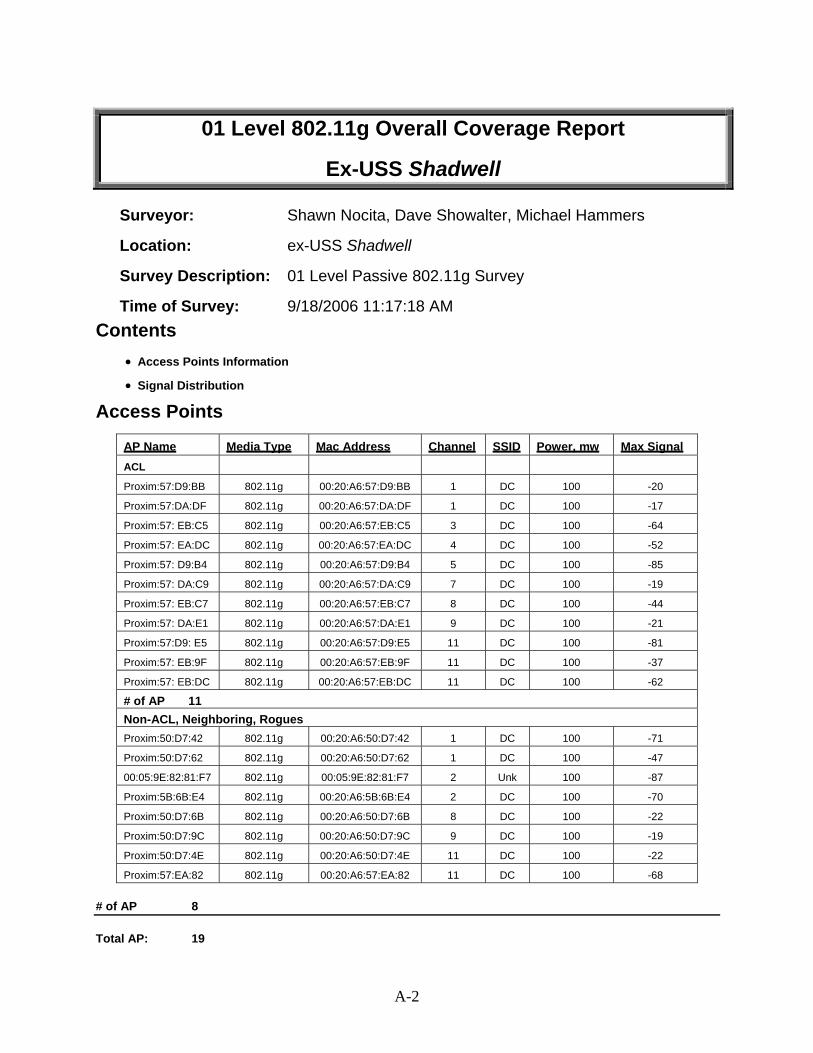
01 Level 802.11g Overall Coverage Report
Ex-USS Shadwell
Surveyor: Shawn Nocita, Dave Showalter, Michael Hammers
Location: ex-USS Shadwell
Survey Description: 01 Level Passive 802.11g Survey
Time of Survey: 9/18/2006 11:17:18 AM Contents
• Access Points Information
• Signal Distribution
Access Points
AP Name Media Type Mac Address Channel SSID Power, mw Max Signal
ACL
Proxim:57:D9:BB 802.11g 00:20:A6:57:D9:BB 1 DC 100 -20
Proxim:57:DA:DF 802.11g 00:20:A6:57:DA:DF 1 DC 100 -17
Proxim:57: EB:C5 802.11g 00:20:A6:57:EB:C5 3 DC 100 -64
Proxim:57: EA:DC 802.11g 00:20:A6:57:EA:DC 4 DC 100 -52
Proxim:57: D9:B4 802.11g 00:20:A6:57:D9:B4 5 DC 100 -85
Proxim:57: DA:C9 802.11g 00:20:A6:57:DA:C9 7 DC 100 -19
Proxim:57: EB:C7 802.11g 00:20:A6:57:EB:C7 8 DC 100 -44
Proxim:57: DA:E1 802.11g 00:20:A6:57:DA:E1 9 DC 100 -21
Proxim:57:D9: E5 802.11g 00:20:A6:57:D9:E5 11 DC 100 -81
Proxim:57: EB:9F 802.11g 00:20:A6:57:EB:9F 11 DC 100 -37
Proxim:57: EB:DC 802.11g 00:20:A6:57:EB:DC 11 DC 100 -62
# of AP 11 Non-ACL, Neighboring, Rogues Proxim:50:D7:42 802.11g 00:20:A6:50:D7:42 1 DC 100 -71
Proxim:50:D7:62 802.11g 00:20:A6:50:D7:62 1 DC 100 -47
00:05:9E:82:81:F7 802.11g 00:05:9E:82:81:F7 2 Unk 100 -87
Proxim:5B:6B:E4 802.11g 00:20:A6:5B:6B:E4 2 DC 100 -70
Proxim:50:D7:6B 802.11g 00:20:A6:50:D7:6B 8 DC 100 -22
Proxim:50:D7:9C 802.11g 00:20:A6:50:D7:9C 9 DC 100 -19
Proxim:50:D7:4E 802.11g 00:20:A6:50:D7:4E 11 DC 100 -22
Proxim:57:EA:82 802.11g 00:20:A6:57:EA:82 11 DC 100 -68
# of AP 8
Total AP: 19
A-2

Signal Distribution Signal Distribution
A-3
A-3
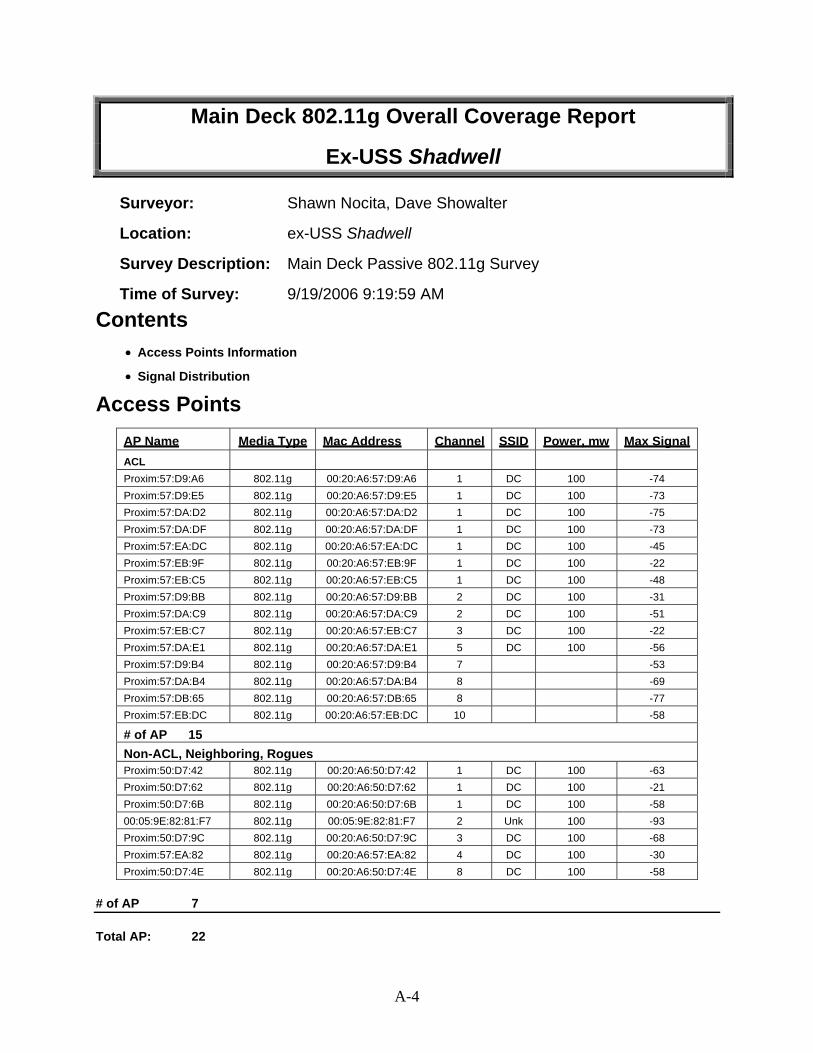
Main Deck 802.11g Overall Coverage Report
Ex-USS Shadwell
Surveyor: Shawn Nocita, Dave Showalter
Location: ex-USS Shadwell
Survey Description: Main Deck Passive 802.11g Survey
Time of Survey: 9/19/2006 9:19:59 AM
Contents • Access Points Information • Signal Distribution
Access Points
AP Name Media Type Mac Address Channel SSID Power, mw Max Signal
ACL
Proxim:57:D9:A6 802.11g 00:20:A6:57:D9:A6 1 DC 100 -74 Proxim:57:D9:E5 802.11g 00:20:A6:57:D9:E5 1 DC 100 -73 Proxim:57:DA:D2 802.11g 00:20:A6:57:DA:D2 1 DC 100 -75 Proxim:57:DA:DF 802.11g 00:20:A6:57:DA:DF 1 DC 100 -73 Proxim:57:EA:DC 802.11g 00:20:A6:57:EA:DC 1 DC 100 -45 Proxim:57:EB:9F 802.11g 00:20:A6:57:EB:9F 1 DC 100 -22 Proxim:57:EB:C5 802.11g 00:20:A6:57:EB:C5 1 DC 100 -48 Proxim:57:D9:BB 802.11g 00:20:A6:57:D9:BB 2 DC 100 -31 Proxim:57:DA:C9 802.11g 00:20:A6:57:DA:C9 2 DC 100 -51 Proxim:57:EB:C7 802.11g 00:20:A6:57:EB:C7 3 DC 100 -22 Proxim:57:DA:E1 802.11g 00:20:A6:57:DA:E1 5 DC 100 -56 Proxim:57:D9:B4 802.11g 00:20:A6:57:D9:B4 7 -53 Proxim:57:DA:B4 802.11g 00:20:A6:57:DA:B4 8 -69 Proxim:57:DB:65 802.11g 00:20:A6:57:DB:65 8 -77 Proxim:57:EB:DC 802.11g 00:20:A6:57:EB:DC 10 -58
# of AP 15 Non-ACL, Neighboring, Rogues Proxim:50:D7:42 802.11g 00:20:A6:50:D7:42 1 DC 100 -63 Proxim:50:D7:62 802.11g 00:20:A6:50:D7:62 1 DC 100 -21 Proxim:50:D7:6B 802.11g 00:20:A6:50:D7:6B 1 DC 100 -58 00:05:9E:82:81:F7 802.11g 00:05:9E:82:81:F7 2 Unk 100 -93 Proxim:50:D7:9C 802.11g 00:20:A6:50:D7:9C 3 DC 100 -68 Proxim:57:EA:82 802.11g 00:20:A6:57:EA:82 4 DC 100 -30 Proxim:50:D7:4E 802.11g 00:20:A6:50:D7:4E 8 DC 100 -58
# of AP 7
Total AP: 22
A-4

Signal Distribution
A-5

2nd Deck 802.11g Overall Coverage Report
Ex-USS Shadwell
Surveyor: Brad Shirley, Dave Showalter
Location: ex-USS Shadwell
Survey Description: 2nd Deck Passive 802.11g Survey
Time of Survey: 9/19/2006 10:44:19 AM
Contents • Access Points Information • Signal Distribution
Access Points
AP Name Media Type Mac Address Channel SSID Power, mw Max Signal ACL
Proxim:57:D9:A6 802.11g 00:20:A6:57:D9:A6 1 DC 100 -51 Proxim:57:D9:E5 802.11g 00:20:A6:57:D9:E5 1 DC 100 -55 Proxim:57:DA:D2 802.11g 00:20:A6:57:DA:D2 1 DC 100 -60 Proxim:57:DA:DF 802.11g 00:20:A6:57:DA:DF 1 DC 100 -76 Proxim:57:EA:DC 802.11g 00:20:A6:57:EA:DC 1 DC 100 -17 Proxim:57:EB:9F 802.11g 00:20:A6:57:EB:9F 1 DC 100 -52 Proxim:57:EB:C5 802.11g 00:20:A6:57:EB:C5 1 DC 100 -18 Proxim:57:D9:9F 802.11g 00:20:A6:57:D9:9F 2 DC 100 -55 Proxim:57:D9:BB 802.11g 00:20:A6:57:D9:BB 2 DC 100 -63 Proxim:57:DA:C9 802.11g 00:20:A6:57:DA:C9 2 DC 100 -75 Proxim:57:EB:C7 802.11g 00:20:A6:57:EB:C7 3 DC 100 -60 Proxim:57:DA:E1 802.11g 00:20:A6:57:DA:E1 5 DC 100 -74 Proxim:57:D9:B4 802.11g 00:20:A6:57:D9:B4 7 DC 100 -58 Proxim:57:D9:97 802.11g 00:20:A6:57:D9:97 8 DC 100 -82 Proxim:57:DA:B4 802.11g 00:20:A6:57:DA:B4 8 DC 100 -69 Proxim:57:DB:65 802.11g 00:20:A6:57:DB:65 8 DC 100 -72 Proxim:57:EB:DC 802.11g 00:20:A6:57:EB:DC 10 DC 100 -18
# of AP 17 Non-ACL, Neighboring, Rogues Proxim:50:D7:42 802.11g 00:20:A6:50:D7:42 1 DC 100 -21 Proxim:50:D7:62 802.11g 00:20:A6:50:D7:62 1 DC 100 -46 Proxim:50:D7:6B 802.11g 00:20:A6:50:D7:6B 1 DC 100 -64 Proxim:50:D7:9C 802.11g 00:20:A6:50:D7:9C 3 DC 100 -72 Proxim:57:EA:82 802.11g 00:20:A6:57:EA:82 4 DC 100 -22 Proxim:50:D7:4E 802.11g 00:20:A6:50:D7:4E 8 DC 100 -87
# of AP 6
Total AP: 23
A-6

Signal Distribution
A-7

3rd Deck 802.11g Overall Coverage Report
Ex-USS Shadwell
Surveyor: Brad Shirley, Dave Showalter
Location: ex-USS Shadwell
Survey Description: 3rd Deck Passive 802.11g Survey
Time of Survey: 9/19/2006 9:32:55 AM
Contents • Access Points Information • Signal Distribution
Access Points
AP Name Media Type Mac Address Channel SSID
Power, mw
Max Signal
ACL
00:20:A6:57:D9:A6 802.11g 00:20:A6:57:D9:A6 1 DC 100 -21 00:20:A6:57:D9:E5 802.11g 00:20:A6:57:D9:E5 1 DC 100 -27 00:20:A6:57:DA:D2 802.11g 00:20:A6:57:DA:D2 1 DC 100 -22 00:20:A6:57:DA:DF 802.11g 00:20:A6:57:DA:DF 1 DC 100 -79 00:20:A6:57:EA:DC 802.11g 00:20:A6:57:EA:DC 1 DC 100 -54 00:20:A6:57:EB:9F 802.11g 00:20:A6:57:EB:9F 1 DC 100 -75 00:20:A6:57:EB:C5 802.11g 00:20:A6:57:EB:C5 1 DC 100 -52 00:20:A6:57:D9:9F 802.11g 00:20:A6:57:D9:9F 2 DC 100 -17 00:20:A6:57:D9:BB 802.11g 00:20:A6:57:D9:BB 2 DC 100 -79 00:20:A6:57:DA:C9 802.11g 00:20:A6:57:DA:C9 2 DC 100 -84 00:20:A6:57:EB:C7 802.11g 00:20:A6:57:EB:C7 3 DC 100 -81 00:20:A6:57:D9:B4 802.11g 00:20:A6:57:D9:B4 7 DC 100 -20 00:20:A6:57:D9:97 802.11g 00:20:A6:57:D9:97 8 DC 100 -69 00:20:A6:57:DA:B4 802.11g 00:20:A6:57:DA:B4 8 DC 100 -32 00:20:A6:57:DB:65 802.11g 00:20:A6:57:DB:65 8 DC 100 -55 00:20:A6:57:EB:DC 802.11g 00:20:A6:57:EB:DC 10 DC 100 -53
# of AP 16 Non-ACL, Neighboring, Rogues 00:20:A6:50:D7:42 802.11g 00:20:A6:50:D7:42 1 DC 100 -55 00:20:A6:50:D7:62 802.11g 00:20:A6:50:D7:62 1 DC 100 -56 00:20:A6:50:D7:6B 802.11g 00:20:A6:50:D7:6B 1 DC 100 -69 00:20:A6:50:D7:9C 802.11g 00:20:A6:50:D7:9C 3 DC 100 -79 00:20:A6:57:EA:82 802.11g 00:20:A6:57:EA:82 4 DC 100 -30
# of AP 5
Total AP: 21
A-8

Signal Distribution
A-9

4th Deck 802.11g Overall Coverage Report
Ex-USS Shadwell
Surveyor: Kenney McCombs, Michael Hammers
Location: ex-USS Shadwell
Survey Description: 4th Deck Passive 802.11g Survey
Time of Survey: 9/18/2006 11:26:35 AM
Contents • Access Points Information • Signal Distribution
Access Points
AP Name Media Type Mac Address Channel SSID
Power, mw
Max Signal
ACL
00:20:A6:57:D9:A6 802.11g 00:20:A6:57:D9:A6 1 DC 100 -53 00:20:A6:57:DA:B4 802.11g 00:20:A6:57:DA:B4 1 DC 100 -26 00:20:A6:57:D9:97 802.11g 00:20:A6:57:D9:97 2 DC 100 -26 00:20:A6:57:EB:C5 802.11g 00:20:A6:57:EB:C5 3 DC 100 -73 00:20:A6:57:D9:9F 802.11g 00:20:A6:57:D9:9F 4 DC 100 -69 00:20:A6:57:D9:B4 802.11g 00:20:A6:57:D9:B4 5 DC 100 -74 00:20:A6:57:DB:65 802.11g 00:20:A6:57:DB:65 8 DC 100 -21 00:20:A6:57:D9:E5 802.11g 00:20:A6:57:D9:E5 11 DC 100 -68 00:20:A6:57:DA:D2 802.11g 00:20:A6:57:DA:D2 11 DC 100 -61
# of AP 9 Non-ACL, Neighboring, Rogues 00:20:A6:50:D7:62 802.11g 00:20:A6:50:D7:62 1 DC 100 -79
00:20:A6:50:D7:6B 802.11g 00:20:A6:50:D7:6B 8 DC 100 -84
00:20:A6:57:EA:82 802.11g 00:20:A6:57:EA:82 11 DC 100 -54
# of AP 3
Total AP: 12
A-10

Signal Distribution
A-11

5th Deck 802.11g Overall Coverage Report
Ex-USS Shadwell
Surveyor: Kenney McCombs, Michael Hammers
Location: ex-USS Shadwell
Survey Description: 5th Deck Passive 802.11g Survey
Time of Survey: 9/18/2006 11:13:37 AM
Contents • Access Points Information • Signal Distribution
Access Points
AP Name Media Type Mac Address Channel SSID
Power, mw
Max Signal
ACL
00:20:A6:57:D9:A6 802.11g 00:20:A6:57:D9:A6 1 DC 100 -53 00:20:A6:57:DA:B4 802.11g 00:20:A6:57:DA:B4 1 DC 100 -26 00:20:A6:57:D9:97 802.11g 00:20:A6:57:D9:97 2 DC 100 -26 00:20:A6:57:EB:C5 802.11g 00:20:A6:57:EB:C5 3 DC 100 -73 00:20:A6:57:D9:B4 802.11g 00:20:A6:57:D9:B4 4 DC 100 -69 00:20:A6:57:DB:65 802.11g 00:20:A6:57:DB:65 5 DC 100 -74 00:20:A6:57:DA:D2 802.11g 00:20:A6:57:DA:D2 8 DC 100 -21
# of AP 7 Non-ACL, Neighboring, Rogues 00:20:A6:50:D7:62 802.11g 00:20:A6:50:D7:62 1 DC 100 -79 00:20:A6:57:EA:82 802.11g 00:20:A6:57:EA:82 8 DC 100 -84
# of AP 2
Total AP: 9
A-12

Signal Distribution
A-13
APPENDIX B
RF DATA FIRE EVENT 1 & FIRE EVENT 2
Test Team One and Test Team Two remained at a stationary location and utilized AirMagnet® Laptop software to take “snapshots” of the RF environment approximately every two minutes. These “snapshots,” referred to as Test Points, produced RF data from the number of access points detected by the software at that specific moment in time.
In the data table, the access point is described by its location on the deck, the last four digits of its MAC address, and the channel on which the AP was operating. For example, the nomenclature AP 1-19-1 STBD PASWAY EBC7 - Channel 3 indicates that the AP is located in the starboard passageway at 1-19-1, its MAC address ends in the character EBC7, and it is operating on Channel 3.
The Test Point nomenclature found in the data table is as follows: Fire Event – Deck – Test Point. Therefore, test point e1-2-12 refers to Fire Event 1 (e1) – 2nd Deck (2) – Test Point 12 (12).
Blank cells indicate that the AirMagnet® software did not detect the signal of the specific AP (access point) or that the AP was “out of range” at that moment. Readings of -100 (Signal) and -100 (Noise) indicate detection of a very weak signal from the access point at that moment.
A higher negative number (more positive) indicates a higher signal level. For instance, -23 dBm is a much stronger signal than -88dBm. Similarly, a higher negative number for noise indicates a higher level of noise. Therefore, a -23-dBm noise level would be an abnormally high level, while typical numbers are closer to -85 dBm on ex-USS Shadwell. The signal/noise ration (S/N) simply indicates how strong the signal is in relation to the noise level. The higher the S/N is, the better the overall VoIP call quality will be.
B-1

FIRE EVENT 1 DATA
FIRE EVENT 1 - MAIN DECK - TEST TEAM 1 AP 1-19-1 STBD PASWAY AP 1-22-1 STBD COMPARTMNT COMMUNICATIONS CASE1 2-22-3
EBC7 - Channel 3 D74E - Channel 8 6BE4 - Channel 4
Test Signal Noise S/N Test Signal Noise S/N Test Signal Noise S/N
Point Point Point
e1-1-1 -19 -72 53 e1-1-1 -81 -96 15 e1-1-1 -73 -89 16
e1-1-2 -18 -77 59 e1-1-2 -79 -96 17 e1-1-2 -73 -85 12
e1-1-3 -24 -74 50 e1-1-3 -82 -96 14 e1-1-3 -72 -89 17
e1-1-4 -16 -72 56 e1-1-4 -82 -96 14 e1-1-4 -74 -89 15
e1-1-5 -18 -68 50 e1-1-5 -78 -96 18 e1-1-5 -71 -89 18
e1-1-6 -18 -64 46 e1-1-6 -80 -96 16 e1-1-6 -75 -89 14
e1-1-7 -22 -66 44 e1-1-7 -80 -96 16 e1-1-7 -79 -88 9
e1-1-8 -20 -68 48 e1-1-8 -79 -96 17 e1-1-8 -82 -88 6
e1-1-9 -22 -77 55 e1-1-9 -81 -96 15 e1-1-9 -100 -100 0
e1-1-10 -28 -74 46 e1-1-10 -81 -96 15 e1-1-10
e1-1-11 -31 -81 50 e1-1-11 -81 -96 15 e1-1-11
e1-1-12 -22 -80 58 e1-1-12 -100 -100 0 e1-1-12
e1-1-13 -27 -83 56 e1-1-13 -100 -100 0 e1-1-13
e1-1-14 -34 -81 47 e1-1-14 -83 -96 13 e1-1-14
e1-1-15 -23 -75 52 e1-1-15 -100 -100 0 e1-1-15
e1-1-16 -13 -74 61 e1-1-16 -100 -100 0 e1-1-16
e1-1-17 -22 -91 69 e1-1-17 -100 -100 0 e1-1-17
e1-1-18 -23 -92 69 e1-1-18 -80 -96 16 e1-1-18
e1-1-19 -23 -92 69 e1-1-19 -82 -96 14 e1-1-19
e1-1-20 -24 -93 69 e1-1-20 -79 -96 17 e1-1-20
e1-1-21 -21 -92 71 e1-1-21 -100 -100 0 e1-1-21
e1-1-22 -21 -93 72 e1-1-22 -79 -96 17 e1-1-22 -100 -100 0
B-2

AP 2-12-1 REPAIR 2 AP 2-19-1 STBD PASWAY AP 1-19-2 PORT COMPARTMNT
EBDC - Channel 10 EBC5 - Channel 11 DAC9 - Channel 2
Test Signal Noise S/N Test Signal Noise S/N Test Signal Noise S/N
Point Point Point
e1-1-1 -68 -83 15 e1-1-1 -66 -84 18 e1-1-1 e1-1-2 -71 -83 12 e1-1-2 -68 -84 16 e1-1-2 e1-1-3 -71 -100 29 e1-1-3 -71 -83 12 e1-1-3 e1-1-4 -100 -100 0 e1-1-4 -71 -85 14 e1-1-4 -100 -100 0 e1-1-5 -71 -81 10 e1-1-5 -69 -82 13 e1-1-5 -100 -100 0 e1-1-6 -74 -83 9 e1-1-6 -68 -84 16 e1-1-6 e1-1-7 -73 -83 10 e1-1-7 -68 -84 16 e1-1-7 e1-1-8 -74 -81 7 e1-1-8 -67 -82 15 e1-1-8 e1-1-9 -72 -100 28 e1-1-9 -69 -84 15 e1-1-9
e1-1-10 -74 -84 10 e1-1-10 -70 -85 15 e1-1-10 e1-1-11 -100 -100 0 e1-1-11 -73 -85 12 e1-1-11 e1-1-12 -100 -100 0 e1-1-12 -72 -87 15 e1-1-12 e1-1-13 -100 -100 0 e1-1-13 -72 -87 15 e1-1-13 e1-1-14 -100 -100 0 e1-1-14 -71 -86 15 e1-1-14 e1-1-15 -74 -86 12 e1-1-15 -66 -89 23 e1-1-15 e1-1-16 -74 -86 12 e1-1-16 -72 -86 14 e1-1-16 e1-1-17 -100 -100 0 e1-1-17 -72 -88 16 e1-1-17 -100 -100 0 e1-1-18 -72 -90 18 e1-1-18 -100 -100 0 e1-1-18 -79 -96 17 e1-1-19 -100 -100 0 e1-1-19 -100 -100 0 e1-1-19 -80 -94 14 e1-1-20 -71 -83 12 e1-1-20 -71 -84 13 e1-1-20 -100 -100 0 e1-1-21 -74 -81 7 e1-1-21 -70 -83 13 e1-1-21 -100 -100 0 e1-1-22 -73 -82 9 e1-1-22 -70 -84 14 e1-1-22 -76 -95 19
B-3

FIRE EVENT 1 - MAIN DECK - TEST TEAM 1 AP 1-29-0 BEHIND SHPFTR SHOP AP 1-22-2 PORT PASWAY AP 2-15-0 REPAIR 2 AFT
D762 - Channel 1 EB9F - Channel 1 D742 - Channel 1
Test Signal Noise S/N Test Signal Noise S/N Test Signal Noise S/N
Point Point Point
e1-1-1 e1-1-1 e1-1-1 e1-1-2 e1-1-2 e1-1-2 e1-1-3 -100 -100 0 e1-1-3 e1-1-3 e1-1-4 e1-1-4 e1-1-4 e1-1-5 -100 -100 0 e1-1-5 e1-1-5 e1-1-6 -100 -100 0 e1-1-6 e1-1-6 e1-1-7 e1-1-7 e1-1-7 e1-1-8 e1-1-8 e1-1-8 e1-1-9 e1-1-9 e1-1-9
e1-1-10 e1-1-10 e1-1-10 e1-1-11 e1-1-11 e1-1-11 e1-1-12 e1-1-12 e1-1-12 e1-1-13 e1-1-13 e1-1-13 e1-1-14 e1-1-14 e1-1-14 e1-1-15 e1-1-15 e1-1-15 e1-1-16 -100 -100 0 e1-1-16 e1-1-16 e1-1-17 -71 -96 25 e1-1-17 -100 -100 0 e1-1-17 -76 -96 20 e1-1-18 -69 -93 24 e1-1-18 e1-1-18 -74 -93 19 e1-1-19 -70 -93 23 e1-1-19 -100 -100 0 e1-1-19 -76 -100 24 e1-1-20 -68 -96 28 e1-1-20 -100 -100 0 e1-1-20 -74 -96 22 e1-1-21 -70 -96 26 e1-1-21 e1-1-21 -75 -96 21 e1-1-22 -67 -96 29 e1-1-22 e1-1-22 -75 -96 21
B-4

AP 1-29-3 NEAR STBD PASWAY
D9BB - Channel 2
Test Signal Noise S/N
Point
e1-1-1 e1-1-2 e1-1-3 e1-1-4 e1-1-5 e1-1-6 e1-1-7 e1-1-8 e1-1-9
e1-1-10 e1-1-11 e1-1-12 e1-1-13 e1-1-14 e1-1-15 e1-1-16 e1-1-17 -80 -96 16 e1-1-18 -100 -100 0 e1-1-19 -77 -94 17 e1-1-20 -77 -96 19 e1-1-21 -80 -96 16 e1-1-22 -76 -95 19
B-5

FIRE EVENT 1 - 2ND DECK - TEST TEAM 2 AP 2-20-2 PORT PASWAY AP 2-15-0 REPAIR 2 AFT AP 3-23-1 STBD PASWAY FWD
EADC - Channel 1 D742 - Channel 1 DAD2 - Channel 1
Test Signal Noise S/N Test Signal Noise S/N Test Signal Noise S/N
Point Point Point
e1-2-1 -81 -94 13 e1-2-1 -68 -94 26 e1-2-1 -73 -94 21 e1-2-2 -100 -100 0 e1-2-2 -66 -94 28 e1-2-2 -75 -94 19 e1-2-3 -100 -100 0 e1-2-3 -66 -89 23 e1-2-3 -74 -89 15 e1-2-4 -100 -100 0 e1-2-4 -67 -94 27 e1-2-4 -80 -94 14 e1-2-5 -100 -100 0 e1-2-5 -100 -100 0 e1-2-5 -75 -92 17 e1-1-6 e1-1-6 -100 -100 0 e1-1-6 -79 -91 12 e1-2-7 e1-2-7 e1-2-7 -76 -91 15 e1-2-8 e1-2-8 e1-2-8 -79 -94 15 e1-2-9 e1-2-9 e1-2-9 -79 -94 15
e1-2-10 e1-2-10 e1-2-10 -79 -94 15 e1-2-11 e1-2-11 -100 -100 0 e1-2-11 -80 -94 14 e1-2-12 e1-2-12 -100 -100 0 e1-2-12 -81 -91 10 e1-2-13 e1-2-13 e1-2-13 -81 -92 11 e1-2-14 e1-2-14 e1-2-14 -81 -91 10 e1-2-15 e1-2-15 e1-2-15 -82 -94 12 e1-2-16 e1-2-16 e1-2-16 -80 -93 13 e1-2-17 e1-2-17 e1-2-17 -80 -94 14 e1-2-18 e1-2-18 e1-2-18 -81 -100 19 e1-2-19 e1-2-19 e1-2-19 -79 -92 13 e1-2-20 e1-2-20 e1-2-20 -79 -94 15 e1-2-21 -100 -100 0 e1-2-21 e1-2-21 -78 -94 16 e1-2-22 e1-2-22 e1-2-22 -77 -100 23 e1-2-23 e1-2-23 -100 -100 0 e1-2-23 -77 -92 15 e1-2-24 e1-2-24 e1-2-24 -72 -94 22 e1-2-25 e1-2-25 e1-2-25 -78 -94 16
B-6

FIRE EVENT 1 - 2ND DECK - TEST TEAM 2 AP 1-29-0 BEHIND SHPFTR SHOP AP 3-16-2 PORT PASWAY FWD AP 1-29-3 NEAR STBD PASWAY
(D762 - Channel 1 D9E5 - Channel 1 D9BB - Channel 2
Test Signal Noise S/N Test Signal Noise S/N Test Signal Noise S/N
Point Point Point
e1-2-1 -83 -100 17 e1-2-1 -100 -100 0 e1-2-1 -100 -100 0 e1-2-2 -84 -94 10 e1-2-2 -100 -100 0 e1-2-2 -100 -100 0 e1-2-3 -100 -100 0 e1-2-3 e1-2-3 -100 -100 0 e1-2-4 -100 -100 0 e1-2-4 e1-2-4 -80 -91 11 e1-2-5 -100 -100 0 e1-2-5 -100 -100 0 e1-2-5 -81 -93 12 e1-1-6 e1-1-6 e1-1-6 -83 -92 9 e1-2-7 -100 -100 0 e1-2-7 e1-2-7 -100 -100 0 e1-2-8 e1-2-8 e1-2-8 -82 -94 12 e1-2-9 e1-2-9 e1-2-9 -81 -100 19
e1-2-10 e1-2-10 e1-2-10 -100 -100 0 e1-2-11 e1-2-11 e1-2-11 -82 -100 18 e1-2-12 e1-2-12 e1-2-12 -100 -100 0 e1-2-13 e1-2-13 e1-2-13 -100 -100 0 e1-2-14 e1-2-14 e1-2-14 -82 -91 9 e1-2-15 e1-2-15 e1-2-15 -82 -94 12 e1-2-16 e1-2-16 e1-2-16 -81 -94 13 e1-2-17 e1-2-17 e1-2-17 -80 -100 20 e1-2-18 e1-2-18 e1-2-18 -100 -100 0 e1-2-19 e1-2-19 e1-2-19 -80 -94 14 e1-2-20 e1-2-20 e1-2-20 -83 -93 10 e1-2-21 e1-2-21 e1-2-21 -83 -94 11 e1-2-22 e1-2-22 e1-2-22 -100 -100 0 e1-2-23 e1-2-23 e1-2-23 -82 -93 11 e1-2-24 -100 -100 0 e1-2-24 e1-2-24 -80 -100 20 e1-2-25 e1-2-25 e1-2-25 -83 -95 12
B-7

FIRE EVENT 1 - 2ND DECK - TEST TEAM 2 AP 3-13-0 BENEATH REPAIR 2 AP 1-19-1 STBD PASWAY COMMUNICATIONS CASE1 2-22-3
D99F - Channel 2 EBC7 - Channel 3 6BE4 - Channel 4
Test Signal Noise S/N Test Signal Noise S/N Test Signal Noise S/N
Point Point Point
e1-2-1 -74 -96 22 e1-2-1 -79 -92 13 e1-2-1 -32 -90 58
e1-2-2 -78 -93 15 e1-2-2 -81 -91 10 e1-2-2 -36 -90 54
e1-2-3 -76 -90 14 e1-2-3 -75 -88 13 e1-2-3 -32 -82 50
e1-2-4 -70 -91 21 e1-2-4 -80 -88 8 e1-2-4 -30 -85 55
e1-2-5 -75 -93 18 e1-2-5 -79 -92 13 e1-2-5 -35 -89 54
e1-1-6 -76 -92 16 e1-1-6 -84 -100 16 e1-1-6 -41 -90 49
e1-2-7 -75 -91 16 e1-2-7 -81 -91 10 e1-2-7 -42 -88 46
e1-2-8 -75 -94 19 e1-2-8 -82 -100 18 e1-2-8 -40 -89 49
e1-2-9 -73 -94 21 e1-2-9 -81 -100 19 e1-2-9 -45 -85 40
e1-2-10 -72 -93 21 e1-2-10 -81 -100 19 e1-2-10 -43 -87 44
e1-2-11 -73 -94 21 e1-2-11 -100 -100 0 e1-2-11 -43 -88 45
e1-2-12 -79 -91 12 e1-2-12 -80 -100 20 e1-2-12 -43 -85 42
e1-2-13 -75 -91 16 e1-2-13 -100 -100 0 e1-2-13 -45 -89 44
e1-2-14 -74 -91 17 e1-2-14 -83 -100 17 e1-2-14 -42 -89 47
e1-2-15 -75 -94 19 e1-2-15 -100 -100 0 e1-2-15 -43 -90 47
e1-2-16 -77 -94 17 e1-2-16 -80 -100 20 e1-2-16 -44 -86 42
e1-2-17 -72 -94 22 e1-2-17 -83 -92 9 e1-2-17 -42 -89 47
e1-2-18 -74 -92 18 e1-2-18 -100 -100 0 e1-2-18 -41 -89 48
e1-2-19 -73 -94 21 e1-2-19 -83 -100 17 e1-2-19 -44 -89 45
e1-2-20 -72 -93 21 e1-2-20 -100 -100 0 e1-2-20 -44 -90 46
e1-2-21 -75 -94 19 e1-2-21 -83 -100 17 e1-2-21 -45 -85 40
e1-2-22 -76 -91 15 e1-2-22 -80 -92 12 e1-2-22 -42 -89 47
e1-2-23 -75 -93 18 e1-2-23 -82 -100 18 e1-2-23 -46 -86 40
e1-2-24 -73 -96 23 e1-2-24 -83 -100 17 e1-2-24 -42 -86 44
e1-2-25 -77 -95 18 e1-2-25 -82 -100 18 e1-2-25 -46 -89 43
B-8

FIRE EVENT 1 - 2ND DECK - TEST TEAM 2 AP 4-24-1 EIOS ROOM AP 3-30-1 STBD PASWAY AFT AP 4-30-4 AFT OF NODE 10
DB65 - Channel 8 D9B4 - Channel 7 DAB4 - Channel 8
Test Signal Noise S/N Test Signal Noise S/N Test Signal Noise S/N
Point Point Point
e1-2-1 -100 -100 0 e1-2-1 -87 -100 13 e1-2-1 -100 -100 0 e1-2-2 e1-2-2 e1-2-2 e1-2-3 e1-2-3 e1-2-3 e1-2-4 e1-2-4 e1-2-4 e1-2-5 e1-2-5 e1-2-5 e1-1-6 e1-1-6 e1-1-6 e1-2-7 e1-2-7 e1-2-7 e1-2-8 e1-2-8 e1-2-8 e1-2-9 e1-2-9 e1-2-9
e1-2-10 e1-2-10 e1-2-10 e1-2-11 e1-2-11 e1-2-11 e1-2-12 e1-2-12 e1-2-12 e1-2-13 e1-2-13 e1-2-13 e1-2-14 e1-2-14 e1-2-14 e1-2-15 e1-2-15 e1-2-15 e1-2-16 e1-2-16 e1-2-16 e1-2-17 e1-2-17 e1-2-17 e1-2-18 e1-2-18 e1-2-18 e1-2-19 e1-2-19 e1-2-19 e1-2-20 e1-2-20 e1-2-20 e1-2-21 e1-2-21 e1-2-21 e1-2-22 e1-2-22 e1-2-22 e1-2-23 e1-2-23 e1-2-23 e1-2-24 e1-2-24 e1-2-24 e1-2-25 e1-2-25 e1-2-25
B-9
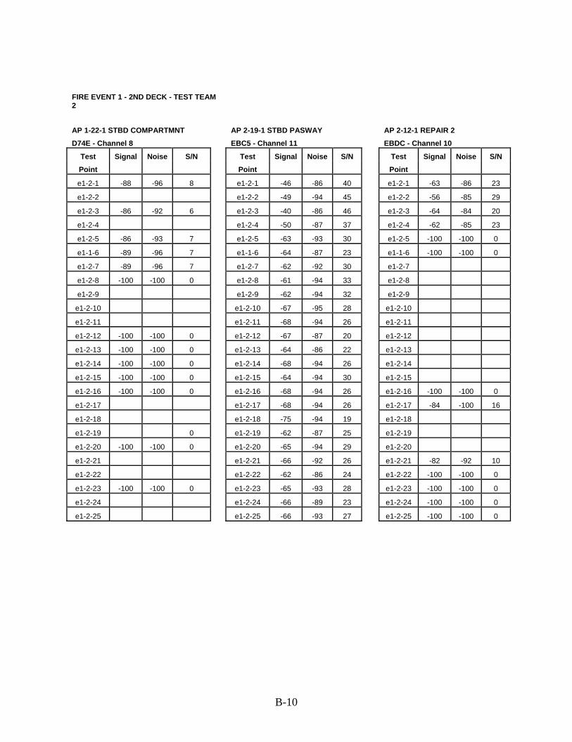
FIRE EVENT 1 - 2ND DECK - TEST TEAM 2 AP 1-22-1 STBD COMPARTMNT AP 2-19-1 STBD PASWAY AP 2-12-1 REPAIR 2
D74E - Channel 8 EBC5 - Channel 11 EBDC - Channel 10
Test Signal Noise S/N Test Signal Noise S/N Test Signal Noise S/N Point Point Point e1-2-1 -88 -96 8 e1-2-1 -46 -86 40 e1-2-1 -63 -86 23 e1-2-2 e1-2-2 -49 -94 45 e1-2-2 -56 -85 29 e1-2-3 -86 -92 6 e1-2-3 -40 -86 46 e1-2-3 -64 -84 20 e1-2-4 e1-2-4 -50 -87 37 e1-2-4 -62 -85 23 e1-2-5 -86 -93 7 e1-2-5 -63 -93 30 e1-2-5 -100 -100 0 e1-1-6 -89 -96 7 e1-1-6 -64 -87 23 e1-1-6 -100 -100 0 e1-2-7 -89 -96 7 e1-2-7 -62 -92 30 e1-2-7 e1-2-8 -100 -100 0 e1-2-8 -61 -94 33 e1-2-8 e1-2-9 e1-2-9 -62 -94 32 e1-2-9
e1-2-10 e1-2-10 -67 -95 28 e1-2-10 e1-2-11 e1-2-11 -68 -94 26 e1-2-11 e1-2-12 -100 -100 0 e1-2-12 -67 -87 20 e1-2-12 e1-2-13 -100 -100 0 e1-2-13 -64 -86 22 e1-2-13 e1-2-14 -100 -100 0 e1-2-14 -68 -94 26 e1-2-14 e1-2-15 -100 -100 0 e1-2-15 -64 -94 30 e1-2-15 e1-2-16 -100 -100 0 e1-2-16 -68 -94 26 e1-2-16 -100 -100 0 e1-2-17 e1-2-17 -68 -94 26 e1-2-17 -84 -100 16 e1-2-18 e1-2-18 -75 -94 19 e1-2-18 e1-2-19 0 e1-2-19 -62 -87 25 e1-2-19 e1-2-20 -100 -100 0 e1-2-20 -65 -94 29 e1-2-20 e1-2-21 e1-2-21 -66 -92 26 e1-2-21 -82 -92 10 e1-2-22 e1-2-22 -62 -86 24 e1-2-22 -100 -100 0 e1-2-23 -100 -100 0 e1-2-23 -65 -93 28 e1-2-23 -100 -100 0 e1-2-24 e1-2-24 -66 -89 23 e1-2-24 -100 -100 0 e1-2-25 e1-2-25 -66 -93 27 e1-2-25 -100 -100 0
B-10

FIRE EVENT 2 DATA
FIRE EVENT 2 - MAIN DECK - TEST TEAM 1 AP 1-19-1 STBD PASWAY AP 1-22-1 STBD COMPARTMNT AP 2-19-1 STBD PASWAY EBC7 - Channel 3 D74E - Channel 8 EBC5 - Channel 11
Test Signal Noise S/N Test Signal Noise S/N Test Signal Noise S/N Point Point Point
e2-1-1 -23 -86 63 e2-1-1 -100 -100 0 e2-1-1 -100 -100 0 e2-1-2 -25 -89 64 e2-1-2 -100 -100 0 e2-1-2 -63 -100 37 e2-1-3 -24 -90 66 e2-1-3 -100 -100 0 e2-1-3 -61 -100 39 e2-1-4 -22 -89 67 e2-1-4 e2-1-4 -55 -100 45 e2-1-5 -20 -88 68 e2-1-5 -100 -100 0 e2-1-5 -100 -100 0 e2-1-6 -21 -90 69 e2-1-6 -76 -83 7 e2-1-6 -61 -100 39 e2-1-7 -23 -86 63 e2-1-7 -100 -100 0 e2-1-7 -67 -100 33 e2-1-8 -17 -84 67 e2-1-8 -100 -100 0 e2-1-8 -100 -100 0 e2-1-9 -23 -89 66 e2-1-9 -74 -83 9 e2-1-9 -100 -100 0
e2-1-10 -24 -88 64 e2-1-10 e2-1-10 -51 -100 49 e2-1-11 -22 -90 68 e2-1-11 e2-1-11 -57 -67 10 e2-1-12 -22 -86 64 e2-1-12 -73 -83 10 e2-1-12 -65 -74 9 e2-1-13 -31 -90 59 e2-1-13 -77 -83 6 e2-1-13 -100 -100 0 e2-1-14 -22 -89 67 e2-1-14 -100 -100 0 e2-1-14 -100 -100 0 e2-1-15 -23 -82 59 e2-1-15 -76 -84 8 e2-1-15 -59 -100 41 e2-1-16 -22 -90 68 e2-1-16 -76 -84 8 e2-1-16 -100 -100 0 e2-1-17 -23 -89 66 e2-1-17 -100 -100 0 e2-1-17 -100 -100 0 e2-1-18 -23 -90 67 e2-1-18 -74 -83 9 e2-1-18 -59 -71 12
COMMUNICATIONS CASE1 2-16-2 AP 2-12-1 REPAIR 2 AP 1-19-2 PORT COMPARTMNT 6BE4 - Channel 4 EBDC - Channel 10 DAC9 - Channel 2
Test Signal Noise S/N Test Signal Noise S/N Test Signal Noise S/N Point Point Point e2-1-1 -100 -100 0 e2-1-1 -100 -100 0 e2-1-1 -72 -95 e2-1-2 -100 -100 0 e2-1-2 e2-1-2 -73 -93 e2-1-3 -100 -100 0 e2-1-3 e2-1-3 -74 -95 21 e2-1-4 e2-1-4 e2-1-4 -81 -93 12 e2-1-5 -100 -100 0 e2-1-5 e2-1-5 -75 -96 21 e2-1-6 -100 -100 0 e2-1-6 e2-1-6 -100 -100 0 e2-1-7 -100 -100 0 e2-1-7 e2-1-7 -74 -95 21 e2-1-8 -87 -92 5 e2-1-8 e2-1-8 -76 -96 20 e2-1-9 -100 -100 0 e2-1-9 e2-1-9 -74 -94 20
e2-1-10 -100 -100 0 e2-1-10 e2-1-10 -72 -94 22 e2-1-11 -100 -100 0 e2-1-11 e2-1-11 -71 -94 23 e2-1-12 -100 -100 0 e2-1-12 e2-1-12 -73 -91 18 e2-1-13 -100 -100 0 e2-1-13 e2-1-13 -78 -91 13 e2-1-14 -100 -100 0 e2-1-14 e2-1-14 -75 -93 18 e2-1-15 -100 -100 0 e2-1-15 e2-1-15 -74 -92 18 e2-1-16 -100 -100 0 e2-1-16 e2-1-16 -74 -95 21 e2-1-17 -87 -92 5 e2-1-17 e2-1-17 -73 -96 23 e2-1-18 -100 -100 0 e2-1-18 -40 -55 15 e2-1-18 -100 -100 0
B-11

AP 1-29-0 BEHIND SHPFTR SHOP AP 1-22-2 PORT PASWAY AP 2-15-0 REPAIR 2 AFT D762 - Channel 1 EB9F - Channel 1 D742 - Channel 1
Test Signal Noise S/N Test Signal Noise S/N Test Signal Noise S/N Point Point Point e2-1-1 -70 -85 e2-1-1 -100 -100 0 e2-1-1 -72 -100 28 e2-1-2 -70 -85 e2-1-2 e2-1-2 -70 -85 15 e2-1-3 -68 -83 15 e2-1-3 e2-1-3 -71 -83 12 e2-1-4 -100 -100 0 e2-1-4 e2-1-4 -100 -100 0 e2-1-5 -71 -82 11 e2-1-5 e2-1-5 -73 -82 9 e2-1-6 -100 -100 0 e2-1-6 e2-1-6 -73 -83 10 e2-1-7 -100 -100 0 e2-1-7 e2-1-7 -100 -100 0 e2-1-8 -70 -83 13 e2-1-8 e2-1-8 -100 -100 0 e2-1-9 -73 -82 9 e2-1-9 e2-1-9 -73 -82 9
e2-1-10 -100 -100 0 e2-1-10 e2-1-10 -100 -100 0 e2-1-11 -100 -100 0 e2-1-11 e2-1-11 -100 -100 0 e2-1-12 -100 -100 0 e2-1-12 e2-1-12 -77 -83 6 e2-1-13 -72 -83 11 e2-1-13 e2-1-13 -74 -83 9 e2-1-14 -70 -83 13 e2-1-14 e2-1-14 -72 -100 28 e2-1-15 -71 -84 13 e2-1-15 e2-1-15 -73 -100 27 e2-1-16 -69 -84 15 e2-1-16 e2-1-16 -73 -84 11 e2-1-17 -100 -100 0 e2-1-17 e2-1-17 -72 -82 10 e2-1-18 -100 -100 0 e2-1-18 e2-1-18 -72 -83 11
FIRE EVENT 2 - MAIN DECK - TEST TEAM 1 AP 1-29-3 NEAR STBD PASWAY D9BB - Channel 2
Test Signal Noise S/N Point e2-1-1 -68 -86 18 e2-1-2 -66 -89 23 e2-1-3 -100 -100 0 e2-1-4 -79 -89 10 e2-1-5 -79 -88 9 e2-1-6 -100 -100 0 e2-1-7 -100 -100 0 e2-1-8 -77 -84 7 e2-1-9 -76 -89 13
e2-1-10 -76 -88 12 e2-1-11 -78 -90 12 e2-1-12 -78 -100 22 e2-1-13 -78 -90 12 e2-1-14 -100 -100 0 e2-1-15 -100 -100 0 e2-1-16 -78 -90 12 e2-1-17 -76 -89 13 e2-1-18 -77 -90 13
B-12

FIRE EVENT 2 - 2ND DECK - TEST TEAM 2 AP 2-12-1 REPAIR 2 AP 3-30-1 STBD PASWAY AFT AP 2-20-2 PORT PASWAY EBDC - Channel 1 D9B4 - Channel 1 EADC - Channel 1
Test Signal Noise S/N Test Signal Noise S/N Test Signal Noise S/N Point Point Point e2-2-1 -70 -92 22 e2-2-1 -100 -100 0 e2-2-1 -100 -100 0 e2-2-2 -77 -94 17 e2-2-2 e2-2-2 e2-2-3 -82 -90 8 e2-2-3 e2-2-3 e2-2-4 -82 -100 18 e2-2-4 e2-2-4 e2-2-5 -100 -100 0 e2-2-5 e2-2-5 e2-2-6 -100 -100 0 e2-2-6 e2-2-6 e2-2-7 e2-2-7 e2-2-7 e2-2-8 e2-2-8 e2-2-8 e2-2-9 e2-2-9 e2-2-9
e2-2-10 e2-2-10 e2-2-10 e2-2-11 e2-2-11 e2-2-11 e2-2-12 e2-2-12 e2-2-12 e2-2-13 e2-2-13 e2-2-13 e2-2-14 e2-2-14 e2-2-14 e2-2-15 e2-2-15 e2-2-15 e2-2-16 e2-2-16 e2-2-16 e2-2-17 e2-2-17 e2-2-17 e2-2-18 e2-2-18 e2-2-18 e2-2-19 e2-2-19 e2-2-19 e2-2-20 e2-2-20 e2-2-20 e2-2-21 -100 -100 0 e2-2-21 e2-2-21 e2-2-22 -100 -100 0 e2-2-22 e2-2-22 e2-2-23 e2-2-23 e2-2-23 e2-2-24 0 e2-2-24 e2-2-24 e2-2-25 -100 -100 0 e2-2-25 e2-2-25
B-13

AP 3-23-1 STBD PASWAY FWD AP 2-19-1 STBD PASWAY AP 1-29-3 NEAR STBD PASWAY DAD2 - Channel 2 EBC5 - Channel 3 D9BB - Channel 4
Test Signal Noise S/N Test Signal Noise S/N Test Signal Noise S/N Point Point Point e2-2-1 -70 -92 22 e2-2-1 -46 -90 44 e2-2-1 -79 -100 21 e2-2-2 -70 -94 24 e2-2-2 -46 -92 46 e2-2-2 -100 -100 0 e2-2-3 -73 -93 20 e2-2-3 -65 -90 25 e2-2-3 e2-2-4 -78 -91 13 e2-2-4 -60 -89 29 e2-2-4 e2-2-5 -76 -92 16 e2-2-5 -66 -88 22 e2-2-5 e2-2-6 -76 -92 16 e2-2-6 -60 -88 28 e2-2-6 e2-2-7 -77 -92 15 e2-2-7 -63 -91 28 e2-2-7 -100 -100 0 e2-2-8 -78 -93 15 e2-2-8 -60 -91 31 e2-2-8 e2-2-9 -78 -92 14 e2-2-9 -62 -90 28 e2-2-9
e2-2-10 -77 -93 16 e2-2-10 -62 -91 29 e2-2-10 e2-2-11 -76 -92 16 e2-2-11 -60 -90 30 e2-2-11 e2-2-12 -77 -92 15 e2-2-12 -63 -90 27 e2-2-12 -100 -100 0 e2-2-13 -76 -92 16 e2-2-13 -59 -90 31 e2-2-13 e2-2-14 -75 -91 16 e2-2-14 -60 -89 29 e2-2-14 e2-2-15 -77 -91 14 e2-2-15 -61 -91 30 e2-2-15 e2-2-16 -78 -91 13 e2-2-16 -60 -91 31 e2-2-16 e2-2-17 -76 -92 16 e2-2-17 -57 -90 33 e2-2-17 -100 -100 0 e2-2-18 -78 -93 15 e2-2-18 -60 -91 31 e2-2-18 -100 -100 0 e2-2-19 -77 -94 17 e2-2-19 -57 -92 35 e2-2-19 -100 -100 0 e2-2-20 -77 -94 17 e2-2-20 -61 -92 31 e2-2-20 e2-2-21 -77 -92 15 e2-2-21 -64 -92 28 e2-2-21 -79 -100 21 e2-2-22 -78 -95 17 e2-2-22 -57 -92 35 e2-2-22 -81 -100 19 e2-2-23 -76 -93 17 e2-2-23 -59 -92 33 e2-2-23 -100 -100 0 e2-2-24 -79 -95 16 e2-2-24 -64 -91 27 e2-2-24 e2-2-25 -73 -92 19 e2-2-25 -58 -91 33 e2-2-25
B-14

FIRE EVENT 2 - 2ND DECK - TEST TEAM 2 AP 1-19-1 STBD PASWAY AP 3-13-0 BENEATH REPAIR 2 COMMUNICATIONS CASE1 2-16-2 EBC7 - Channel 4 D99F - Channel 4 6BE4 - Channel 9
Test Signal Noise S/N Test Signal Noise S/N Test Signal Noise S/N Point Point Point e2-2-1 -77 -100 23 e2-2-1 -72 -87 15 e2-2-1 -83 -94 11 e2-2-2 -80 -100 20 e2-2-2 -75 -91 16 e2-2-2 -100 -100 0 e2-2-3 -78 -100 22 e2-2-3 -74 -100 26 e2-2-3 -100 -100 0 e2-2-4 -100 -100 0 e2-2-4 -100 -100 0 e2-2-4 e2-2-5 -77 -100 23 e2-2-5 -77 -85 8 e2-2-5 -100 -100 0 e2-2-6 -80 -88 8 e2-2-6 -74 -88 14 e2-2-6 e2-2-7 -100 -100 0 e2-2-7 -74 -88 14 e2-2-7 e2-2-8 -100 -100 0 e2-2-8 -74 -88 14 e2-2-8 e2-2-9 -100 -100 0 e2-2-9 -74 -88 14 e2-2-9
e2-2-10 -79 -100 21 e2-2-10 -73 -88 15 e2-2-10 e2-2-11 -79 -88 9 e2-2-11 -73 -88 15 e2-2-11 e2-2-12 -77 -100 23 e2-2-12 -75 -89 14 e2-2-12 e2-2-13 -80 -100 20 e2-2-13 -74 -88 14 e2-2-13 e2-2-14 -78 -100 22 e2-2-14 -75 -100 25 e2-2-14 e2-2-15 -77 -100 23 e2-2-15 -77 -100 23 e2-2-15 e2-2-16 -77 -100 23 e2-2-16 -73 -88 15 e2-2-16 e2-2-17 -78 -100 22 e2-2-17 -73 -87 14 e2-2-17 e2-2-18 -78 -90 12 e2-2-18 -75 -90 15 e2-2-18 e2-2-19 -79 -89 10 e2-2-19 -76 -89 13 e2-2-19 e2-2-20 -77 -100 23 e2-2-20 -75 -89 14 e2-2-20 e2-2-21 -78 -89 11 e2-2-21 -75 -100 25 e2-2-21 e2-2-22 -78 -89 11 e2-2-22 -75 -89 14 e2-2-22 e2-2-23 -78 -89 11 e2-2-23 -74 -100 26 e2-2-23 e2-2-24 -89 -100 11 e2-2-24 -74 -86 12 e2-2-24 e2-2-25 -79 -100 21 e2-2-25 -73 -100 27 e2-2-25
B-15

AP 1-29-0 BEHIND SHPFTR SHOP AP 2-29-0 AFT PLATFORM AP 1-22-1 STBD COMPARTMNT D762 - Channel 11 EA82 - Channel 9 D74E - Channel 11
Test Signal Noise S/N Test Signal Noise S/N Test Signal Noise S/N Point Point Point e2-2-1 -100 -100 0 e2-2-1 -100 -100 0 e2-2-1 -100 -100 0 e2-2-2 -100 -100 0 e2-2-2 e2-2-2 e2-2-3 e2-2-3 e2-2-3 e2-2-4 e2-2-4 e2-2-4 e2-2-5 e2-2-5 e2-2-5 e2-2-6 e2-2-6 e2-2-6 e2-2-7 e2-2-7 e2-2-7 e2-2-8 e2-2-8 e2-2-8 e2-2-9 e2-2-9 e2-2-9
e2-2-10 e2-2-10 e2-2-10 e2-2-11 e2-2-11 e2-2-11 -100 -100 0 e2-2-12 e2-2-12 e2-2-12 e2-2-13 e2-2-13 e2-2-13 -100 -100 0 e2-2-14 e2-2-14 e2-2-14 e2-2-15 e2-2-15 e2-2-15 e2-2-16 e2-2-16 e2-2-16 e2-2-17 e2-2-17 e2-2-17 e2-2-18 e2-2-18 e2-2-18 e2-2-19 e2-2-19 e2-2-19 e2-2-20 e2-2-20 e2-2-20 e2-2-21 -78 -91 13 e2-2-21 e2-2-21 e2-2-22 e2-2-22 e2-2-22 e2-2-23 e2-2-23 e2-2-23 e2-2-24 e2-2-24 e2-2-24 e2-2-25 -81 -90 9 e2-2-25 e2-2-25
B-16

FIRE EVENT 2 - 2ND DECK - TEST TEAM 2 AP 2-15-0 REPAIR 2 AFT D742 - Channel 11
Test Signal Noise S/N Point e2-2-1 -70 -85 15 e2-2-2 -73 -87 14 e2-2-3 -73 -91 18 e2-2-4 e2-2-5 e2-2-6 e2-2-7 e2-2-8 e2-2-9
e2-2-10 e2-2-11 e2-2-12 e2-2-13 e2-2-14 e2-2-15 e2-2-16 e2-2-17 e2-2-18 e2-2-19 e2-2-20 e2-2-21 e2-2-22 -80 -91 11 e2-2-23 e2-2-24 e2-2-25
B-17

APPENDIX C
SPP QUALITY TEST RESULTS
Approximate Location of SPP Nodes
Corresponding SPP Tag Information
Signal Quality Comments
01 Level1. 01-47-0 Unmarked FIRE TESTS 1,2,3 Located in DC Central 2. 01-48-1 15 INST TR Active Monitoring Station; No jack/plug-in 3. 01-40-2 1 JV 14 Active Located in Sick Bay 4. 01-40-2 2 JZ #3 Inactive Located in Sick Bay Main Deck5. 1-41-2 Unmarked Active Located in passageway 6. 1-41-2 2 JZ 17 Inactive Located in passageway 7. 1-43-1 1 JV 1-43 Inactive Located in passageway 8. 1-43-1 2 JZ 16 Inactive Located in passageway 9. 1-30-1 X 40 J Active Located in passageway 10. 1-24-2 1 JV 2 Active Located in cage area inside Machine Room 11. 1-24-2 1 JV 9 Active Located in cage area inside Machine Room 12. 1-24-2 Unmarked Inactive Located in cage area inside Machine Room
13. 1-25-1 15 INST TR Active Monitoring Station; No jack/plug-in; Located on bulkhead inside room
14. 1-25-1 Unmarked Active Located on bulkhead inside room 15. 1-25-1 2 JZ #5 Inactive Located on bulkhead inside room 16. 1-25-1 1 JV-9 Active Located on bulkhead inside room 17. 1-25-1 1 JV-2 Inactive Located on bulkhead inside room 18. 1-19-2 1 JV-12 Active Located in passageway 19. 1-18-1 2 JZ #6 Inactive Located on bulkhead inside Machine Room 20. 1-18-1 1 JV 26 Active Located on bulkhead inside Machine Room 21. 1-20-1 1 JV 1-20 FIRE TEST 1, 2 Located in passageway 22. 1-10-0 X 40 J FIRE TEST 3 Located outside near forward of ship 2nd Deck23. 2-22-2 2 JV 15 Inactive Located on bulkhead inside room 24. 2-14-1 Unmarked Active Located on bulkhead inside room
25. 2-12-1 2 JX #6 Inactive Monitoring Station; Located on bulkhead outside Repair Locker 2
26. 2-10-1 Unmarked Active Located on bulkhead inside Repair Locker 2 3rd Deck27. 3-17-4 1 JV 12 Inactive Located on bulkhead inside room 4th Deck
28. 4-21-4 Call Signal Station Type ICD
Active Located on bulkhead inside room
5th Deck
C-1

APPENDIX D
Acronyms AP .................................................................................................................................Access Point °C ......................................................................................................Degrees Centigrade or Celsius CIC........................................................................................................ Combat Information Center CPO.....................................................................................................................Chief Petty Officer CRIDCC...........................Crew Reductions through Improved Damage Control Communications dB......................................................................................... Decibel (measure of sound amplitude) DC...........................................................................................................................Damage Control EDG .................................................................................................... Emergency Diesel Generator EM........................................................................................................................... Electromagnetic °F........................................................................................................................ Degrees Fahrenheit FNC.......................................................................................................... Future Naval Capabilities FR............................................................................................................................................ Frame FTL .......................................................................................................................Fire Team Leader IP .............................................................................................................................Internet Protocol kW.................................................................................................. Kilowatt (One Thousand Watts) LAN ..................................................................................................................Local Area Network Mbps ...................................... Mega baud per second (one million bits of information per second) MAC .......................................................................................................... Medium Access Control MTS.................................................................................Management & Technology Services Inc. PC........................................................................................................................Personal Computer PDA..........................................................................................................Personal Digital Assistant PLC .....................................................................................................Power Line Communications PO .................................................................................................................................Petty Officer PSGWY.......................................................................................................................... Passageway RF........................................................................................................................... Radio Frequency SCBA ....................................................................................... Self-Contained Breathing apparatus SPP................................................................................................................ Sound Powered Phone STBD .................................................................................................................................Starboard VoIP .....................................................................................................Voice over Internet Protocol WAV.........................................................................Windows Wave (audio format/file extension) WIFCOM .......................................................................................Wireless force Communications WLAN.................................................................................................Wireless Local Area network
D-1