future of low head turbines concerning environmental aspect · pdf file1 future of low head...
TRANSCRIPT
1
Future of Low Head Turbines Concerning Environmental Aspect
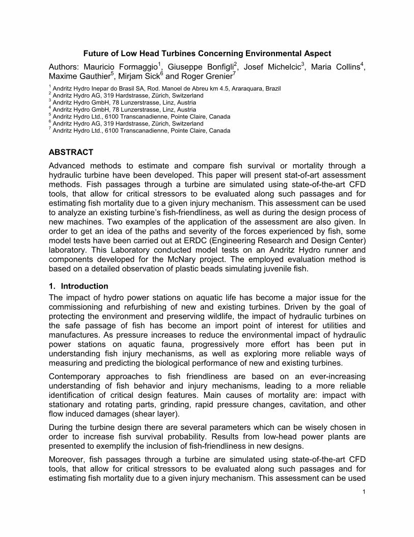
Authors: Mauricio Formaggio1, Giuseppe Bonfigli2, Josef Michelcic3, Maria Collins4, Maxime Gauthier5, Mirjam Sick6 and Roger Grenier7 1 Andritz Hydro Inepar do Brasil SA, Rod. Manoel de Abreu km 4.5, Araraquara, Brazil
2 Andritz Hydro AG, 319 Hardstrasse, Zürich, Switzerland
3 Andritz Hydro GmbH, 78 Lunzerstrasse, Linz, Austria
4 Andritz Hydro GmbH, 78 Lunzerstrasse, Linz, Austria
5 Andritz Hydro Ltd., 6100 Transcanadienne, Pointe Claire, Canada
6 Andritz Hydro AG, 319 Hardstrasse, Zürich, Switzerland
7 Andritz Hydro Ltd., 6100 Transcanadienne, Pointe Claire, Canada
ABSTRACT
Advanced methods to estimate and compare fish survival or mortality through a hydraulic turbine have been developed. This paper will present stat-of-art assessment methods. Fish passages through a turbine are simulated using state-of-the-art CFD tools, that allow for critical stressors to be evaluated along such passages and for estimating fish mortality due to a given injury mechanism. This assessment can be used to analyze an existing turbine’s fish-friendliness, as well as during the design process of new machines. Two examples of the application of the assessment are also given. In order to get an idea of the paths and severity of the forces experienced by fish, some model tests have been carried out at ERDC (Engineering Research and Design Center) laboratory. This Laboratory conducted model tests on an Andritz Hydro runner and components developed for the McNary project. The employed evaluation method is based on a detailed observation of plastic beads simulating juvenile fish.
1. Introduction
The impact of hydro power stations on aquatic life has become a major issue for the commissioning and refurbishing of new and existing turbines. Driven by the goal of protecting the environment and preserving wildlife, the impact of hydraulic turbines on the safe passage of fish has become an import point of interest for utilities and manufactures. As pressure increases to reduce the environmental impact of hydraulic power stations on aquatic fauna, progressively more effort has been put in understanding fish injury mechanisms, as well as exploring more reliable ways of measuring and predicting the biological performance of new and existing turbines.
Contemporary approaches to fish friendliness are based on an ever-increasing understanding of fish behavior and injury mechanisms, leading to a more reliable identification of critical design features. Main causes of mortality are: impact with stationary and rotating parts, grinding, rapid pressure changes, cavitation, and other flow induced damages (shear layer).
During the turbine design there are several parameters which can be wisely chosen in order to increase fish survival probability. Results from low-head power plants are presented to exemplify the inclusion of fish-friendliness in new designs.
Moreover, fish passages through a turbine are simulated using state-of-the-art CFD tools, that allow for critical stressors to be evaluated along such passages and for estimating fish mortality due to a given injury mechanism. This assessment can be used

2
to analyze an existing turbine’s fish-friendliness, as well as during the design process of new machines. Two examples of the application of the assessment are also given.
Finally it is shown another manner to enhance the environmental aspect of modern turbines based on oil free hub design concept for double regulated machines.
2. Fish Survival Assessment
2.1. Background
In the past, managing the survival of fish passing through hydraulic turbines has consisted mainly of active measures. For example, fish screens and bypasses allow downstream migrating fish to circumvent the hydraulic passages and running turbines. In addition, the number of active turbines during the periods of heavy fish migration can be reduced. Also, turbines can be operated at the best efficiency point (BEP), under the assumption that this operating point is the best for fish survival.
However, these measures are no longer sufficient for modern hydraulic turbines. Power plant operators want to minimize the amount of water passed without producing power, and so there is pressure to reduce the amount of water passing through fish bypasses and spillways. Operators also want access to wider range of operating conditions, and not only keep their turbines running at the BEP. And finally, no measure can guarantee that fish would not pass through running turbines.
With increasing pressure from environmental and political sources, turbine manufacturers are expected to answer more and more questions regarding fish passage through hydraulic passages and turbines. These questions vary depending on the client and on the project scope, but a typical approach to assessing the “fish-friendliness” of a turbine is a comparative estimate of fish survival.
To provide such an estimate requires a good understanding of the effects of turbine passage on fish. Thankfully, recent studies have expanded our knowledge and understanding of turbine-related fish injuries. Relevant injury mechanisms have been identified and linked to physical stressors. In addition, researchers have started compiling dose-response data in order to better estimate fish survival levels. In parallel, modern computational fluid dynamics (CFD) tools can be used to model the passage of fish through hydraulic passages. The combination of these studies and CFD tools forms the basis of a fish survival assessment.
2.2. Overview
A typical fish survival assessment consists of three principal steps: identification of the fish injury mechanisms, linking the injury mechanisms to stressors and compiling the dose-response data.
“Injury mechanisms” encompass all the ways that passage through a hydraulic turbine can endanger the lives of fish. In general, injury mechanisms can be separated into direct and indirect mechanisms.
Direct mechanisms are potentially fatal injuries suffered by the fish during turbine passage. The principal direct injury mechanisms include: rapid pressure drops, cavitation, shear stress, turbulence, strikes on blades and vanes, grinding and abrasion.

3
Figure 1 shows a selection of these injury mechanisms and the position in the hydraulic passage where fish are likely to encounter them.
Indirect mechanisms are the sum of all the non-lethal effects and consequences of turbine passage that can lead to increased mortality in fish populations (increased downstream predation, adversely affected fish behavior, etc.). In general, indirect mechanisms are very difficult to evaluate and are usually neglected from fish survival assessments.
Stressors: stressors are the measurable, physical quantities that can be linked to each injury mechanism. By evaluating the exposure of the fish to a given stressor, we can infer the probability that a fish suffer injury or fatality due to a given mechanism. A list of common injury mechanisms and their linked stressors are listed in table 1 below.
Figure 1 : Examples of fish injury mechanisms in a hydraulic power plants (Čada, 2001)
Table 1 : Injury mechanisms and related stressors
Injury mechanisms Stressors
Rapid pressure drop Fish acclimation pressure &
Absolute pressure Cavitation Absolute pressure
Shear stress Vorticity or strain rate Turbulence Velocity and pressure fluctuations
Blade strikes Impact intensity Other mechanical Injuries: vane strikes, grinding, abrasion, etc.
Fish trajectory and velocities (see following pages)
4
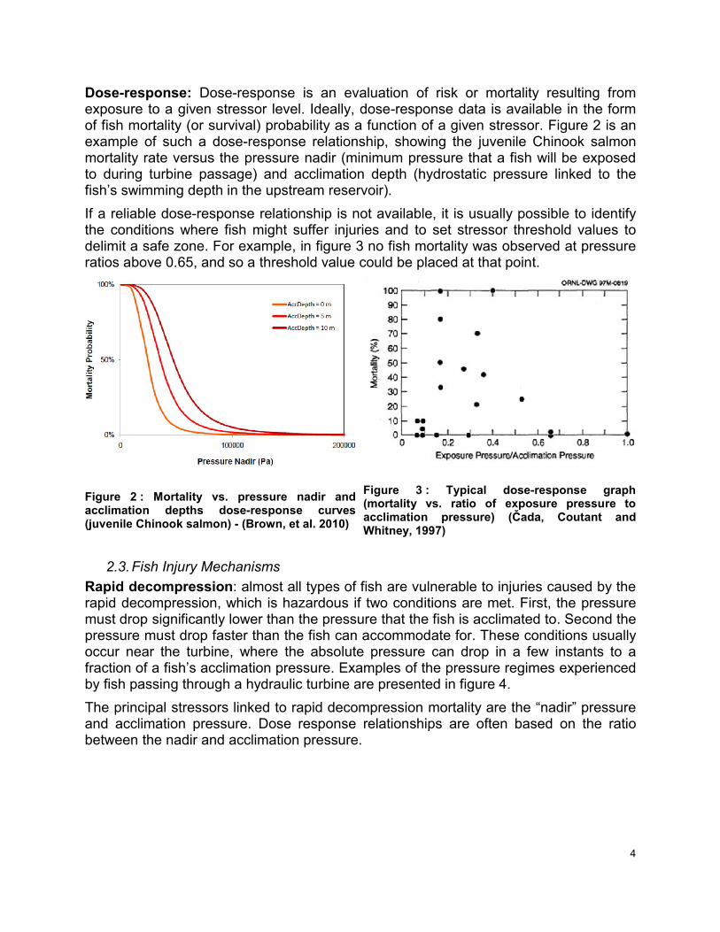
Dose-response: Dose-response is an evaluation of risk or mortality resulting from exposure to a given stressor level. Ideally, dose-response data is available in the form of fish mortality (or survival) probability as a function of a given stressor. Figure 2 is an example of such a dose-response relationship, showing the juvenile Chinook salmon mortality rate versus the pressure nadir (minimum pressure that a fish will be exposed to during turbine passage) and acclimation depth (hydrostatic pressure linked to the fish’s swimming depth in the upstream reservoir).
If a reliable dose-response relationship is not available, it is usually possible to identify the conditions where fish might suffer injuries and to set stressor threshold values to delimit a safe zone. For example, in figure 3 no fish mortality was observed at pressure ratios above 0.65, and so a threshold value could be placed at that point.
Figure 2 : Mortality vs. pressure nadir and acclimation depths dose-response curves (juvenile Chinook salmon) - (Brown, et al. 2010)
Figure 3 : Typical dose-response graph (mortality vs. ratio of exposure pressure to acclimation pressure) (Čada, Coutant and Whitney, 1997)
2.3. Fish Injury Mechanisms
Rapid decompression: almost all types of fish are vulnerable to injuries caused by the rapid decompression, which is hazardous if two conditions are met. First, the pressure must drop significantly lower than the pressure that the fish is acclimated to. Second the pressure must drop faster than the fish can accommodate for. These conditions usually occur near the turbine, where the absolute pressure can drop in a few instants to a fraction of a fish’s acclimation pressure. Examples of the pressure regimes experienced by fish passing through a hydraulic turbine are presented in figure 4.
The principal stressors linked to rapid decompression mortality are the “nadir” pressure and acclimation pressure. Dose response relationships are often based on the ratio between the nadir and acclimation pressure.

5
Figure 4 : Pressure regimes in laboratory study (simulating pressure experienced by fish passing turbines) (Abernethy, Amidan and Čada 2002)
Response of fish to rapid decompression varies greatly from one species to another, and so pressure-related dose-response relationships are species-specific. For example, the dose-response graph in figure 2 is only valid for Chinook salmon.
Cavitation: Cavitation is believed to be extremely hazardous to fish, but in reality experimental data on cavitation-related injuries is practically inexistent. However, cavitation injuries can often be neglected from a fish survival assessment, because the regions of the turbine flow where cavitation conditions occur already fall in the region where the absolute pressure is low enough to cause decompression-related mortality.
Shear stress: High shear in the hydraulic passages can cause injuries by inducing localized bending, compression and stretching loads on the fish.
High shear stress can be observed in the distributor, near the trailing edges of the stay vanes and wicket gates, and near the runner blades. The stressor linked to this injury is the vorticity or the strain rate.
It is difficult to determine the actual effects of turbine passage shear on fish. First, there is relatively little mortality data available for shear-related injuries, and so it is hard to set realistic mortality threshold values for stressors linked to shear. In addition, it is unclear

6
if the tests used to collect shear mortality data (such as the test section described in figure 5) reproduce the effects of turbine-related shear in a realistic manner.
Figure 5 : Close-up of shear test facility showing fish deployment into test environment (Neitzel, et al. 2004)
Turbulence: In general, turbulence in hydraulic passages can be separated between small and large scale effects, which affect fish differently (see figure 6). Turbulence at small scales (length scales smaller than the fish length) is present in the same locations as high shear, and lead to similar injuries (compression, stretching, bending, etc.). Thus, small scale turbulence injuries can often be lumped with shear stress injuries.
Large scale turbulence (length scales longer than the fish) affects fish differently: such turbulence causes disorientation and increased stress on the fish. Such effects taken alone do not harm the fish, but increase the incidence of indirect mortality, which is usually not taken into account for fish survival assessments.
The stressor linked to turbulence-related injuries is the turbulence kinetic energy (TKE).
Figure 6 : Effects of different turbulence scales on fish (Čada and Odeh, 2001)
Blade Strikes: high-energy impacts between the fish and the rotating runner blades are a significant source of injury for all runner types, and significant analysis has been put into ways to quantify the risks related to blade strikes.

7
Franke (Franke et al. 1997) developed an analytical blade strike equation (1) to calculate the probability of fish being killed due to an impact with the blade leading edge, based on a simplified representation of a fish and runner blade in the meridional plane in figure 7. In equation (1), the blade strike mortality PMortality,Strike is proportional to the strike probability PStrike. In turn, PStrike is function of the number of blades, the length of the fish, the runner diameter, the runner speed and the flow velocity profile upstream of the runner.
rVLNPP a
StrikeStrikeMortality
2
sin
2 1
, (1)
Figure 7 : Sketch of meridional view of runner blade and a passing fish (Franke et al. 1997)
In equation (1), “λ” is the mortality coefficient, or the proportion of fish that are killed after impacting the blade leading edge. Ideally, this coefficient can be derived from blade strike mortality data available from a similar power plant. However, such data is often not readily available, and thus the mortality coefficient must be based on the best fit of existing experimental data.
Even though, the analytical blade strike equation is well known and recognized in the industry, it is based on several unrealistic assumptions: for example, the fish are modeled as rigid, passive one-dimensional objects, and only impacts with the leading edges are considered.
Another approach to evaluating the blade strike mortality is to evaluate the severity or intensity of the impacts. The strike intensity approach estimates the mortality probability of each strike as a function of the normal velocity of the impact, as well as the ratio of the fish length (L) to the blade thickness (t). This approach is based on studies linking fish mortality to the velocity of the runner relative to the blade and to the L/t ratio (see figure 8, from Amaral, Hecker and Dixon, 2001).
This approach gives blade strike predictions based on the fish trajectories modeled in CFD simulations or by bead trajectory model tests. In addition, by generalizing the blade thickness by the radius of curvature at the point of impact (see figure 9), this model can be applied to any blade surface. The available fish mortality data as a function of the velocity and L/t ratio is still very sparse, thus, it is difficult to construct a reliable dose-response relationship and results using this method remain uncertain.

8
Figure 8 : Direct mortality to leading edge strike as function of strike speed and L/t ratio (rainbow trout) (Amaral, Hecker and Dixon 2001)
Figure 9 : Determining the equivalent length-to-thickness ratio
Other injury mechanisms: these mechanisms include strikes with the stationary components (such as stay vanes, guide vanes and walls), abrasion (friction injuries due to fish rubbing on surfaces) and grinding (fish being squeezed and entrained in gaps smaller than the size of the fish).
Since they are not part of typical fish survival assessments, an approach to dealing with these injury mechanisms is to implement design features aimed at minimizing exposure to stationary component strikes, abrasion and grinding.
2.4. Fish Trajectory Modeling
Reasonably reliable predictions of fish paths through a hydraulic turbine are needed in order to correctly assess fish survival. Modern CFD simulations provide two such prediction tools: streamlines and particle tracks.
Streamlines: in a CFD turbine simulation, streamlines can be used as surrogates for the paths that fish would follow and the level of exposure to different stressors can be evaluated along each streamline (see figure 10).
This approach is simple and straightforward, since all CFD post-processing software can easily generate and analyze streamlines. On the other hand, streamlines model the fish as passive, massless and dimensionless objects, and neglects the possible effects of the fish’s shape and behavior on the fish paths. Also, streamlines do not allow for direct strike injury predictions since they do not impact the blades and walls.
Particle Tracks are a more advanced approach to simulating fish paths through a turbine. Particle tracks add inertia to the simulated fish trajectories, giving more accurate path predictions compared to streamlines. In addition, particle tracks allow for direct strike predictions based on the relative velocity of impacts on the walls and on the local shape of the wall at the point of impact. As with streamlines, exposure levels to different stressors can be evaluated along the particle tracks (see figure 11).
Particle tracks models account for mass but not for shape and size (dimensionless particles). This may lead to unrealistic trajectory predictions, such as particles passing

9
through gaps smaller than the fish’s size. Also, this approach still models the fish as passive objects. Finally, particle tracks are very difficult to manipulate and greatly increase the computation costs.
Figure 10 : Example of streamlines as fish surrogates (colored by absolute pressure)
Figure 11 : Example of particle tracks as fish surrogates (colored by absolute pressure)
3. Examples of Applications of Fish Survival Assessments
3.1. Keeyask Proposal
Description: In a 2011 study, Andritz Hydro explored a CFD-based procedure to evaluate the fish-friendliness of hydraulic turbines and applied this procedure on different proposed turbine geometries for the Keeyask power plant on the Lower Nelson River in Manitoba, Canada. The investigations performed during this study served as a basis for Andritz Hydro’s fish survival assessment.
After a review of existing literature on turbine-related fish injuries and on the application of CFD to evaluate the exposure of fish to critical stressors, it was decided to concentrate the study on the three injury mechanisms perceived as the most hazardous to fish: rapid pressure drop, high shear stress and blade strikes.
It was not possible to derive valid dose-response relationships for pressure drop related injuries and shear stress related injuries due to a lack biological data about the concerned species of fish. Instead, the assessment relied on threshold criteria based on available fish mortality data. From Stephenson, et al. (2010), a threshold absolute pressure of 50kPa to avoid pressure drop injury was chosen, and from Neitzel et al. (2004), a threshold strain rate of 500s-1, to avoid shear stress related injuries, was chosen.
Injuries from strikes on blades and on other walls were evaluated by studying the velocity and the local curvature at the point of impact between the modeled fish and walls. Based on the results of Amaral, Hecker and Dixon (2001, see figure 8), Andritz Hydro extracted a fish survival probability map (figure 12) based on the velocity and the L/t ratio (equivalent to the ratio between fish length and curvature radius at the point of impact). The available data proved too sparse to create a reliable mortality probability map, thus a simplified map with a threshold limit between “safe” conditions (no mortality due to strikes) and “dangerous” conditions (risk of mortality due to strikes) was designed (figure 13).

10
Figure 12 : Survival probability map as a function of the normal velocity and L/t ratio
Figure 13 : Strike safety threshold based on normal strike velocity and length-to-thickness ratio
The steady-state CFD simulations were performed using the CFX (v13.0) commercial software. The hydraulic passages were modeled from the forebay to the outlet of the draft tube. In order to simplify the simulations, the full passage was split in 2 domains: a first group including the intake, semi-spiral casing and full distributor (figure 14a) and a second group with a single passage of the guide vane, and runner and the draft tube, joined together with stage-type interfaces between rotating and non-rotating domains (figure 14b).
Figure 14 : Breakdown of CFD simulation domain groups a) Intake, semi-spiral casing and distributor b) One guide vane, one runner blade and draft tube
The Lagrangian particle tracking model included in CFX-Solver represent the fish as spherical, neutrally buoyant and inelastic particles. The particles are released with a (roughly) equal spacing distribution at the inlet. During post-processing, the minimum absolute pressure and maximum strain rate are evaluated on each particle track, and the impacts between the particle tracks and the walls are evaluated. Each CFD

11
simulation can be scored by evaluating the number of particle tracks where the safety threshold for a given injury mechanism (PInjury) are exceeded. Under the assumption that a fish has an equal probability of following a given track, PInjury can be calculated with equation (2), where NInjury is the number of tracks where the threshold for a given criteria has been exceed and NTotal is the total number of simulated tracks.
Total
Injury
InjuryN
NP %100 (2)
Results and Discussion: based on the procedure described above, CFD simulations for two different proposed runner geometries were run and fish survival assessment results for two different fish sizes were compiled in table 2.
Table 2 : Fish survival assessment results for the Keeyask proposal
Fish length and weight L = 190 mm
(W = 0.074 kg) L = 300 mm
(W = 0.261 kg)
Intake, casing and distributor Minimum pressure < 50 kPa 0% 0% Shear Strain Rate < 500 s
-1 0% 0%
Dangerous Strike Probability 0% 0%
Guide vane, runner and draft tube Runner A: 5 blades
Minimum pressure < 50 kPa 13.9% 21% Shear Strain Rate < 500 s
-1 6.1% 11.1%
Dangerous Strike Probability 2.5% 3.9%
Guide vane, runner and draft tube Runner B: 4 blades
Minimum pressure < 50 kPa 8.5% 12.5% Shear Strain Rate < 500 s
-1 5.1% 7.2%
Dangerous Strike Probability 3.2% 3%
The first notable element is the apparent lack of danger in the casing and the distributor. Indeed, there are virtually no regions of dangerous pressures or shear strain in this domain. Also, while there were a high amount of impacts in the distributor region, the relative velocities of the impacts were very low and thus were not considered dangerous.
CFD simulations of guide vane-runner-draft tube domain show that the most dangerous region of the turbine passage is near the runner blades, where the absolute pressure drops below 50kPa and shear strain exceeds 500s-1 (see figure 15). This explains why the pressure and strain rate injury scores in table 2 decrease between the 5-bladed and 4-bladed runner. Also, it was determined that the only impacts that were dangerous occurred on the runner blade, and that these impacts were concentrated mostly on or near the blade leading edge (see figure 15).

12
a) b)
Figure 15 : Strikes on blade and regions exceeding pressure and strain rate thresholds a) Runner A (5-blades) at rated head b) Runner B (4 blades) at rated head
3.2. Borgharen Case
Description: In 2011, Andritz Hydro carried out a study to investigate possible alternatives to improve turbine design in order to maximize to fish survival during turbine passage for Borgharen hydro-power plant on the river Meuse, with main focus on eels and juvenile salmons.
Survival rates for one single turbine and for the entire power plant were compared to those observed at the similar hydro-power plant in Linne, located further downstream. The hydro-power plant Borgharen was designed to be equipped with horizontal bulb machines similar to the pit units in use in Linne. For both turbines the runner diameter is 4m, maximum discharge around 100m^3/s and net head of 5m. Field monitoring of fish mortality at the Linne power plant has been performed over the last two decades and provided a valuable data base to gauge and validate the theoretical approaches used to evaluate fish mortality at Borgharen.
Two layouts were evaluated as possible alternatives for the Borgharen turbine: a three-blade runner with a rotational speed of 115rpm and a four-blade runner with a rotational speed of 100rpm. The turbines installed at Linne are equipped with three-blade runners with rotational speed of 88rpm. Even though it is know that larger number of blades and the higher rotational speed increases the fish mortality, such layout for Borgharen turbines were optimized for the specific operating range.
Results and Discussion: The assessment of fish survival done by Andritz Hydro for the Borgharen power plant proves that state-of-art of most recent CFD simulations together with existing similar power plant fish survival data base is a very powerful tool to supply the most efficient hydraulic turbines, both in terms of performance and environment.
For Borgharen case, both three and four blade runners were considered to perform slightly worse than the Linne turbine with respect to blade-strike mortality, as an immediate consequence of the rotational speed and number of blades. If mortality rates for Borgharen are compared to Linne for equal turbine discharge, the three-blade runner

13
achieves lower mortality rates than the four-blade runner (3 and 1 percentage points less mortality for eel and juveniles salmonids, respectively) but higher mortality rates than the Linne turbine (3 and 1 percentage points more mortality for eel and salmonids, respectively).
Additional factor influencing the fish mortality is the operating scheme which comprehends the number of running turbines at a given available discharge and the portion of discharge bypassing the power plant. A demonstration of the potential for mortality reduction connected to the definition of the operating scheme is provided in Figure 16. For a given river discharge the higher is the discharge per turbine the minimum is the mortality rate. Overall mortality can be reduced by delaying the start of additional turbines until already running turbines have reached full load
Figure 16 : Computed mortality rates for turbine-passed eel in a bulb turbine as a function of the river discharge: operating scheme used before optimization (blue) vs. optimized operating
scheme with delayed start of additional turbines (red).
The three-blade runner was recommended as optimal solution for the Borgharen power station because it is advantageous both with regards to fish survival and energy production.
3.3. Biological Performance Assessment (BioPA) Tool
Description: Developed by the Pacific Northwest National Laboratory (PNNL) in Richland, WA, USA, the BioPA tool provides a fish survival assessment based on the CFD simulations of a hydraulic turbine. The BioPA tool provides a performance indicator that can be used to compare different turbine design layouts and geometries. It was developed to assess whether proposed replacement turbines for the Priest Rapids power plant (Columbia River, WA, USA) could match or exceed the existing turbine’s performance.
The BioPA is applied to a steady-state CFD simulation of the complete hydraulic passage (from the trash rack to the tailrace), with the results being analyzed using the Tecplot 360 software. The BioPA tool uses streamlines, with a uniform seeding at the intake, as surrogates for the fish paths.
The tool evaluates critical stressor values (minimum absolute pressure, maximum strain rate and maximum turbulence kinetic energy) on each streamline and calculates a probability density function (PDF) of the exposure to each stressor. The tool then

14
combines these exposure probabilities with mortality PDFs extracted from existing mortality studies on an endemic fish species in the Columbia River (Chinook salmon) to get a performance indicator for three injury mechanisms (rapid pressure drop, shear and turbulence).
The performance indicator for blade strikes is handled slightly differently: for each streamline, the tool evaluates a blade strike probability based on the number of blades, speed, flow conditions, fish length and blade geometry, and combines this strike probability with a mortality coefficient based on the fish size and relative velocity to obtain a mortality probability for each streamline. The blade strike performance indicator is the average blade strike mortality probability for all the streamlines.
Results and Discussion: The BioPA tool outputs a single overall performance indicator which makes it easy to compare proposed turbine geometries and layouts to the existing design. The performance indicator may not be a reliable estimate of the fish mortality, but if a proposed turbine matches or surpasses an existing turbine’s score than that proposed turbine can be expected to have equivalent or better fish survival results.
Also, by studying the breakdown of the scoring for the existing turbine, it is possible to identify the most critical elements affecting fish survival and use that knowledge to orient the efforts of the proposal and design work.
The BioPA tool showed itself as a powerful tool for evaluating comparative fish survival performance, even though it was calibrated for the specific considerations of the Priest Rapids project (see Figure 17). However, if properly treated, the BioPA’s could be generalized to analyze just about any type of turbine. In addition, running the BioPA on existing turbines where good fish mortality data is available could help calibrate the BioPA tool and it could eventually be used to make reliable fish survival estimates.
Figure 17 : Priest Rapids Dam

15
3.4. McNary Refurbishment Project
Description: In 2002, former GE Hydro and VA Tech (both owned by Andritz Hydro) awarded a contract from the US Government Corps of Engineers (USCOE) to develop and apply a fish friendly runner and water passage modifications for the McNary Dam, located on the Columbia river.
The complete development of Andritz Hydro consisted of 19 new runners, modification of the stay vane nose and tail, new wicket gate design without overhang (patent No US 7114918), and modifications on the draft tube elbow, pier nose and diffuser. The selected runner and the drawings of modified component were sent to USCOE Friendly Evaluation Laboratory – ERDC (Engineering Research and Development Center) for evaluation tests.
The method used at ERDC for fish friendly evaluation is based on observation of plastic beads, which simulate juvenile fish, as they travel through a fully homologous Plexiglas model (see Figure 18 and Figure 19). The bead observations are done through the support of a high speed camera looking through the Plexiglas Model. The recorded digital video is then replayed at a sufficiently low speed for good visualization of the bead trajectories, which are ranked based on the disturbance severity they experience.
Figure 18 : Casing portion of McNary Plexiglas Model at ERDC Laboratory
Figure 19 : Andritz Hydro Runner in Plexiglas Model of ERDC Laboratory
Results and Discussion: The disturbance severity of the bead path was recorded for original McNary model and its results of fish friendly evaluation served as basis for comparison of new and modified components.
One particular comment Andritz Hydro received from USCOE after evaluation was concerning the new runner design:
“Significant Strength - The proposed runner performs exceptionally well. Flow coming off the runner is very smooth. There were significantly fewer severe bead contacts and significantly fewer beads exhibiting sudden changes in direction. Hydraulic shear (flow acceleration) below runner was significantly reduced. The flow and beads transition very smoothly from the runner through the throat and elbow into the draft-tubes. This runner would appear to provide significantly improved fish passage conditions as compared to the existing runner and was noted as providing a “snow flake” effect because the beads appeared to smoothly drift down from the runner into the draft-tubes.”

16
4. Keeping the Water Clean
Hydro power generation is recognized as a pollution free method of energy production. The growing intolerance to inadvertent of even very small amounts of oil into rivers is an incentive to reduce the quantity of oil applied to hydro-turbines.
Typical double-regulated machines have oil-filled hubs, where the oil lubricates the trunnion and mechanism bearings. In such cases the pressure inside the runner hub is higher than outside, so that in the event of trunnion seal problem oil will leak out of the hub rather than water seeping in, occasionally damaging the bearing.
4.1. Oil free hub
The aim of this design which is known as “oil free hub” is to safely prevent any oil, which is used for positioning the runner blades, to leak into the river.
Oil free hubs have been developed and applied for many years, mainly in Scandinavia (Sweden and Finland), where the environmental requirements, traditionally have been very strict.
For many years, developments have been done to avoid such damage to the environment by applying proper design for both classical oil filled hub as well as for the even safer “oil free hub”.
The design of “oil free hub” consists of a servomotor located inside the runner hub and which has the surrounding space filled with water and additives for corrosion protection. For such a design there is no risk of oil leakage into the river water and the blade seal arrangement prevents water exchange (see Figure 20Error! Reference source not found.).
Figure 20: Oil free hub (ANDRITZ design example)
Figure 21: Detail of Runner Blade Seal
The “Oil free hub” design has a major positive impact on the water quality and thus on the environment compared to the traditional design.

17
5. References
[1] Abernethy, C. S., B. G. Amidan, and Glenn F. Čada. “Simulated passage through a modified Kaplan turbine pressure regime: A supplemement to laboratory studies of the effect of pressure and dissolved gas supersaturation on turbine-passed fish. Report submitted to the U.S. DOE, Richland, WA, USA: Pacific Northwest Naional Laboratories, 2002.
[2] Amaral, Stephen V., George Hecker , and Douglas A. Dixon. "Designing Leading Edges of Turbine Blades to Increase Fish Survival from Blade Strike”,." Paper presented at EPRI Conference on Environmentally-Enhanced Hydropower Turbines. Washington, D.C., USA, May 2001.
[3] Brown, R. S., et al. "Assessment of Barotrauma in Untagged and Tagged Juvenile Chinook Salmon Exposed to Simulated Hydro-Turbine Passage." Richland, WA, USA: Pacific Northwest National Laboratory, 2010,cited in Richmond, Marshall C., John A. Serkowski, Thomas J. Carlson, Laurie L. Ebner, Mirjam Sick, and Glenn F. Čada. "Computational Fluid Dynamics Framework for Turbine Biological Performance Assessment." Paper presented at EPRI Conference on Environmentally-Enhanced Hydropower Turbines. Washington D.C., USA, May 2011.
[4] Čada , Glenn F., and Mufeed Odeh. "Turbulence At Hydroelectric Power Plants And Its Potential Effects On Fish." Report to Bonneville power Administration (BPA Rport DOE/BP-26531-1), 2001.
[5] Čada, Glenn F. "The Development of Advanced HydroElectric Turbines to Improve Fish Passage Survival." Fisheries 26, no. 9 (September 2001): 14-23.
[6] Čada, Glenn F., Charles C. Coutant, and Richard R. Whitney. Development of Biological Criteria for the Design of Advanced Hydropower Turbines. Report for the U.S. DOE, Oak Ridge, TN, USA: Oak Ridge National Laboratories, 1997.
[7] Cook, Thomas C., George E. Hecker, Henry B. Faulkner, and Willem Jansen. Development of a more Fish Friendly Turbine Runner. Advanced Hydropower Turbine Project (Contract DE-AC07-95ID13383), Holden, MA, USA: Alden Research Laboratory, 1997.
[8] Franke, Gary F., et al. "Development of Environmentally Advanced Hydropower Turbine System Design Concepts." Report Prepared for US Department of Energy, Energy Efficiency and Renewable Energy, Hydropower Research Foundation, DOE Idaho Operations Office Contract DE-AC07-941D13223, 1997.
[9] Keller, M., M. Sick, and R. Grunder. "CFD-Based Assessment of Fish-Friendliness of the Time Dependant Flow Field in a Kaplan Runner." HydroVision. 2006.
[10] Neitzel, Duane D., et al. "Survival estimates for juvenile fish subjected to a laboratory-generated shear environment." Transactions of the American Fisheries Society, no. 133 (2004): 447-454.
18
[11] Nietzel, Duane A., Dennis Dauble, Marshall Richmond, and Glenn F. Čada. Developing Biological Specifications for Fish Friendly Turbines. Report written for the Advanced Hydropower Turbine System Program (U.S. Department of Energy), Richland, WA, USA: Pacific Northwest National Laboratories, n.d.
[12] Richmond, Marshall C, John A Serkowski, C L Rakowski, B Strickler, M Weisbeck, and C L Dotson. "Design Tools to Assess Hydro-Turbine Biological Performance: Priest Rapids Dam Turbine Replacement Project." HydroVision 2013. Denver, CO.
[13] Richmond, Marshall C., John A. Serkowski, Thomas J. Carlson, Laurie L. Ebner, Mirjam Sick, and Glenn F. Čada. "Computational Fluid Dynamics Framework for Turbine Biological Performance Assessment." Paper presented at EPRI Conference on Environmentally-Enhanced Hydropower Turbines. Washington D.C., USA, May 2011.
[14] Sick, M., Q. Liang, L. Ebner, and J. Kiel. "A further step towards CFD based assessment of fish survival in a Kaplan hydro power station." Water Power, 2009.
[15] Stephenson, John R., et al. "Assessing barotraumas in neutrally and negatively buoyant juvenile salmonids exposed to simulated hydro-turbine passage using a mobile aquatic barotraumas laboratory." Fisheri”es Research 106, 2010: 271-278, cited in Hecker, George, and Gregory S. Allen. "An Approach to Predicting Fish Survival for Advanced HydroTurbines." Hydro Review, November 2005: 36-43.
6. Authors Biography
Mauricio Formaggio joined Andritz Hydro Inepar in 2007, and works in the R&D department. He works as hydraulic design engineer with a main focus on computational fluid dynamics. He is graduated in “Mechanical Engineering” at Universidade de São Paulo.
Giuseppe Bonfigli joined Andritz Hydro in 2011. He works on the development of software tools for hydraulic design of radial and axial turbines. His main field of expertise is computational fluid dynamics. He holds a master degree in aeronautical engineering from the Politecnico di Milano, Italy, and PhD from the University of Stuttgart, Germany.
Josef Michelcic is graduated in “Mechanical Engineering” at Technical University Vienna/Austria. The main focus in his studies was the Hydraulic Turbomachinery and the Thermal Turbomachinery. Since 2011 he is working as a design engineer for Andritz Hydro GmbH in the research and development department. He works for axial turbines and static parts with a main focus on computational fluid dynamics.
Maria Collins joined Andritz Hydro GmbH in 2011. She works as a design engineer for radial and axial turbines with a main focus on computational fluid dynamics. She graduated in Aviation at the University for Applied Sciences in Graz/Austria and did her doctoral studies of engineering sciences at the Graz University of Technology. Afterwards she worked as a research assistant at the Institute for Thermal

19
Turbomachinery and Machine Dynamics at the Graz University of Technology. Her professional interest is in turbulence and transition modeling.
Maxime Gauthier joined Andritz Hydro Ltd. in 2009, and works in the Hydraulic Engineering department designing CFD-based tools for design engineers. He holds a bachelor’s degree in mechanical engineering and a master’s degree in aerospace engineering from the École Polytechnique de Montréal.
Mirjam Sick is head of Engineering Methods in the R&D department of ANDRITZ HYDRO. After obtaining her PhD from the Faculty of Mechanical Engineering of the University of Karlsruhe she worked as CFD specialist and project manager on several turbomachinery projects in Sulzer Innotec. She joined ANDRITZ HYDRO (then: Sulzer Hydro) in 1997 and has been working on turbine design and pursuing complex CFD projects such as draft tube vortex flow and dynamic load analysis including structural and mechanical analysis.
Roger Grenier joined GE Hydro (now Andritz Hydro) in 1981. He is currently Manager of Hydraulic Engineering at Andritz Hydro's Pointe-Claire location. He holds a bachelor's degree in mechanical Engineering from the Université de Sherbrooke.