fuzzy control of motion of underwater robotic · pdf filefuzzy control of motion of underwater...
TRANSCRIPT
Fuzzy Control of Motion of Underwater Robotic Vehicle
JERZY GARUS
Faculty of Mechanical and Electrical Engineering
Naval University
81-103 Gdynia, ul. Smidowicza 69
POLAND
[email protected] http://www.amw.gdynia.pl
Abstract: - The paper addresses nonlinear control of an underwater robot. A way-point line of sight scheme is
incorporated to following a desired path. Command signals are generated by an autopilot consisting of three
fuzzy controllers. A methods of thrust distribution among propellers in the robot’s propulsion system is also
proposed. Optimisation of thrust allocation is directed towards minimisation of energy expenditures necessary
to obtain required control. Some computer simulations are provided to demonstrate effectiveness, correctness
and robustness of the approach.
Key-Words: - Underwater robot, Fuzzy control, Propulsion system, Thrust allocation
1 Introduction Underwater Robotics has known an increasing
interest in the last years. The main benefits of usage
of Underwater Robotic Vehicles (URV) can be
removing a man from dangers of the undersea
environment and reduction of costs of exploration
of deep seas. Currently, it is common to use the
URVs to accomplish such missions as the
inspections of coastal and off-shore structures,
cable maintenances, as well as hydrographical and
biological surveys. In a military field they are
employed in such tasks as a surveillance, an
intelligence gathering, a torpedo recovery and mine
counter measures.
The URV is considered as a floating platform
carrying tools required for performing various
functions. These include manipulator arms with
interchangeable end-effectors, cameras, scanners,
sonars, etc. An automatic control of the such object
is a difficult problem caused by its nonlinear
dynamics [2, 4, 5, 6]. Moreover, the dynamics can
change according to the alteration of configuration
to be suited to the mission. In order to cope with
these difficulties, the control system should be
flexible.
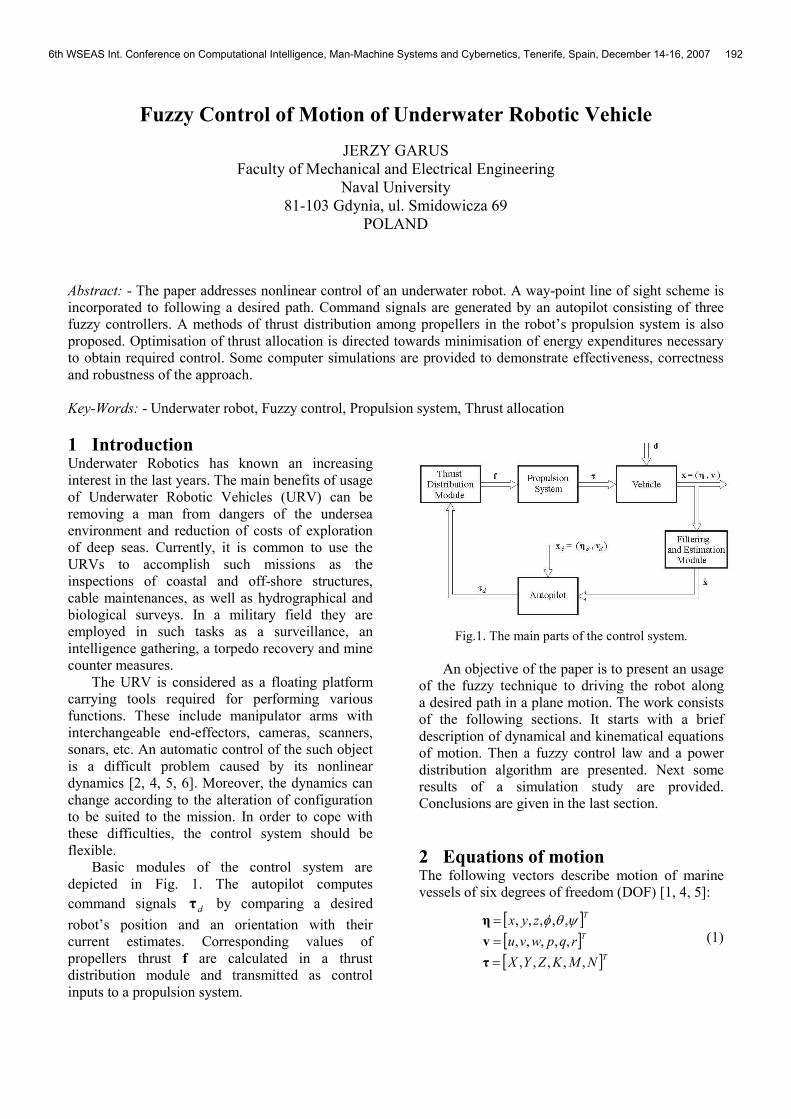
Basic modules of the control system are
depicted in Fig. 1. The autopilot computes
command signals dτ by comparing a desired
robot’s position and an orientation with their
current estimates. Corresponding values of
propellers thrust f are calculated in a thrust
distribution module and transmitted as control
inputs to a propulsion system.
Fig.1. The main parts of the control system.
An objective of the paper is to present an usage
of the fuzzy technique to driving the robot along
a desired path in a plane motion. The work consists
of the following sections. It starts with a brief
description of dynamical and kinematical equations
of motion. Then a fuzzy control law and a power
distribution algorithm are presented. Next some
results of a simulation study are provided.
Conclusions are given in the last section.
2 Equations of motion The following vectors describe motion of marine
vessels of six degrees of freedom (DOF) [1, 4, 5]:
[ ][ ][ ]T
T
T
NMKZYX
rqpwvu
zyx
,,,,,
,,,,,
,,,,,
=
=
=
τ
v
η ψθφ (1)
6th WSEAS Int. Conference on Computational Intelligence, Man-Machine Systems and Cybernetics, Tenerife, Spain, December 14-16, 2007 192

where:
η – position and orientation vector in
an inertial system;
x, y, z – coordinates of position;
φ, θ, ψ – coordinates of orientation (Euler angles);
v – linear and angular velocity vector
with coordinates in a body-fixed
system;
u, v, w – linear velocities along longitudinal,
transversal and vertical axes;
p, q, r – angular velocities about longitudinal,
transversal and vertical axes;
ττττ – vector of forces and moments acting
on it robot in the body-fixed system;
X, Y, Z – forces along longitudinal, transversal
and vertical axes;
K, M, N – moments about longitudinal,
transversal and vertical axes.
Nonlinear dynamical and kinematical equations
of motion in body-fixed system can be expressed as
[4, 5]:
( )vηJη
τηgvvDvvCvM
=
=+++
�
� )()()( (2)
where:
M – inertia matrix (including added
mass);
C(v) – matrix of Coriolis and centripetal
terms (including added mass);
D(v) – hydrodynamic damping and lift
matrix;
)(ηg – vector of gravitational forces and
moments;
)(ηJ – velocity transformation matrix
between body fixed system and
inertial one.
3 Path following and course keeping
control It is convenient to define three coordinate systems
when analysing the underwater robot’s motion in
a horizontal plane (see Fig. 1) [4, 6]:
1. the global coordinate system O0X0Y0 (called
also the earth-fixed system);
2. the local coordinate system OXY (fixed to
a body of the robot);
3. the reference coordinate system PiXiYi (system
is not fixed).
The main task of the control system is to
minimize a distance of an attitude of the robot’s
centre of gravity d to the desired path under
assumptions:
1. the robot can move with varying linear
velocities u, v and angular velocity r;
2. its positions x, y and heading ψ are
measurable;
3. the command signal ττττ consists of three
components: Xτ and Yτ - forces respectively in
x- and y-axis, Nτ - moment around z-axis;
4. travel time is not fixed, it means the navigation
between two points is not constrained by time.
Fig.2. Coordinate systems used to description of motion
in the horizontal plane: O0X0Y0 – earth-fixed system,
OXY – body-fixed system, PiXiYi – reference system.
The autopilot has to provide both path
following and course keeping capabilities. Hence, it
should minimize mean squares of deviations d from
the desired track and ψ∆ from the desired course:
( ) ( )[ ]∑ ∆+= ttdJt
22min ψλ (3)
where:
( ) ( );)()cos()()sin()( 00 ii ytyxtxtd −∆+−∆−= ψψ ;
itt ϕψψ −=∆ )()( ;
)(tψ - robot’s heading angle;
iϕ – angle of rotation of reference coordinate
system with respect to global one:
−−
=+
+
ii
iii
xx
yyarctg
1
1ϕ
λ – constant coefficient.
6th WSEAS Int. Conference on Computational Intelligence, Man-Machine Systems and Cybernetics, Tenerife, Spain, December 14-16, 2007 193
Each time a robot’s location ( ))(),( 00 tytx at the
time t satisfies:
( )[ ] ( )[ ] 2
0
2
01
2
01 ρ≤−+− ++ tyytxx ii (4)
where ρ0 is a circle of acceptance, the reference
coordinate system PiXiYi changed into
Pi+1Xi+1Yi+1, the angle of rotation 1+iφ calculated
and its position updated corresponding to the new
reference coordinate system.
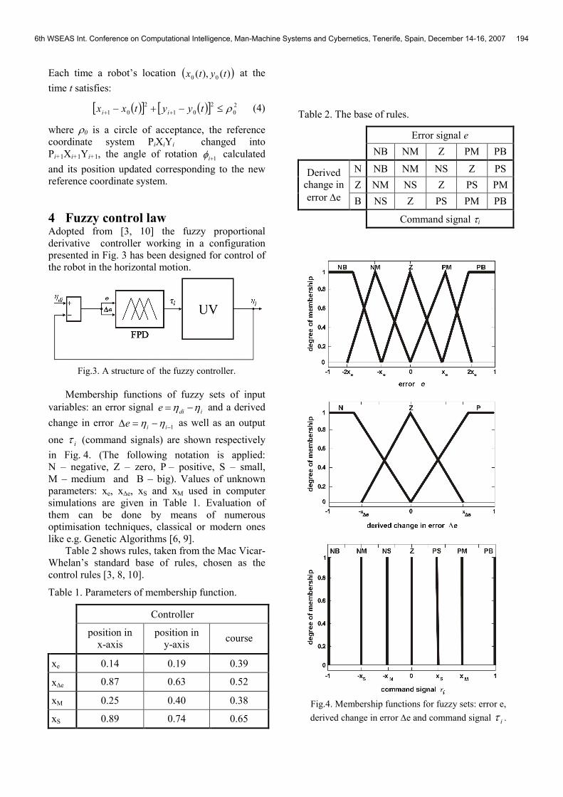
4 Fuzzy control law Adopted from [3, 10] the fuzzy proportional
derivative controller working in a configuration
presented in Fig. 3 has been designed for control of
the robot in the horizontal motion.
Fig.3. A structure of the fuzzy controller.
Membership functions of fuzzy sets of input
variables: an error signal idie ηη −= and a derived
change in error 1−−=∆ iie ηη as well as an output
one iτ (command signals) are shown respectively
in Fig. 4. (The following notation is applied:
N – negative, Z – zero, P – positive, S – small,
M – medium and B – big). Values of unknown
parameters: xe, x∆e, xS and xM used in computer
simulations are given in Table 1. Evaluation of
them can be done by means of numerous
optimisation techniques, classical or modern ones
like e.g. Genetic Algorithms [6, 9].
Table 2 shows rules, taken from the Mac Vicar-
Whelan’s standard base of rules, chosen as the
control rules [3, 8, 10].
Table 1. Parameters of membership function.
Controller
position in
x-axis
position in
y-axis course
xe 0.14 0.19 0.39
x∆e 0.87 0.63 0.52
xM 0.25 0.40 0.38
xS 0.89 0.74 0.65
Table 2. The base of rules.
Error signal e
NB NM Z PM PB
N NB NM NS Z PS
Z NM NS Z PS PM
Derived
change in
error ∆e B NS Z PS PM PB
Command signal τi
Fig.4. Membership functions for fuzzy sets: error e,
derived change in error ∆e and command signal iτ .
6th WSEAS Int. Conference on Computational Intelligence, Man-Machine Systems and Cybernetics, Tenerife, Spain, December 14-16, 2007 194
5 Procedure of power distribution Basic motion of the URVs is movement in
a horizontal plane with some variation due to
diving. They operate in crab-wise manner in four
DOF with small roll and pitch angles that can be
neglected during normal operations. Therefore, it is
on purpose to regard three-dimensional motion of
the robot as superposition of two displacements:
motion in the horizontal plane and motion in the
vertical plane. It allows to divide a its power
transmission system into two independent
subsystems, i.e. the subsystem realizing vertical
motion and the subsystem responsible for
horizontal motion. A general structure of the
propulsion system shows Fig. 5.
Fig.5. A structure of power transmission system with
five propellers
The second subsystem consists of four
propellers mounted askew in relation to main axes
of symmetry and assures surge, sway and yaw
motion. Demanded inputs, i.e. forces along roll and
lateral axes and moment around vertical axis, are
linear combination of thrusts of propellers produced
by the all subsystem. Hence, from an operating
point of view, the control system should have
a procedure of power distribution among the
propellers.
Relationship between the vector of forces and
moments τ acting on the vehicle and the thrust vector of propellers f is a complicated nonlinear
function depending on density of water, a tunnel
length and a cross-sectional area, a propeller
diameter and its revolutions and the robot’s
velocity [5].
In many practical applications it is
approximated by so called simplified model, i.e. the
system being linear in its input [4]:
Tfτ = (5)
where:
[ ]TNYX τττ ,,=τ
T – propellers configuration matrix,
[ ]Tnfff ,...,, 21=f – thrust vector.
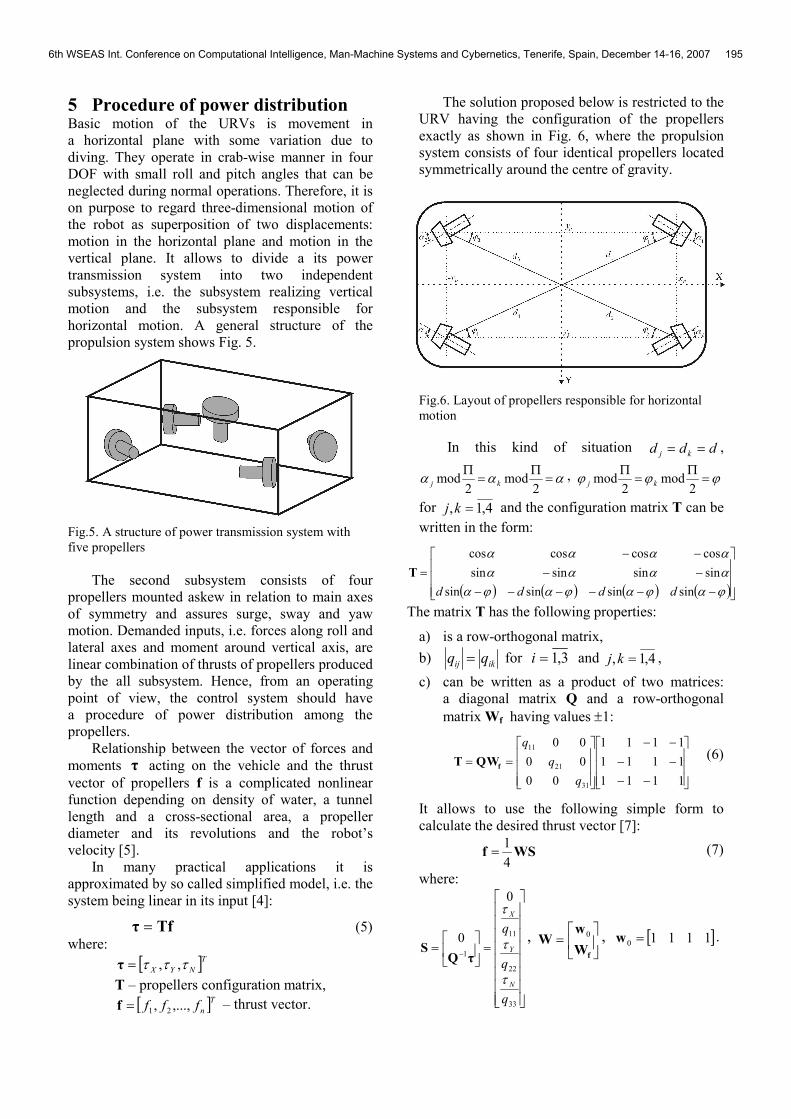
The solution proposed below is restricted to the
URV having the configuration of the propellers
exactly as shown in Fig. 6, where the propulsion
system consists of four identical propellers located
symmetrically around the centre of gravity.
Fig.6. Layout of propellers responsible for horizontal
motion
In this kind of situation ddd kj == ,
ααα =Π
=Π
2mod
2mod kj
, ϕϕϕ =Π
=Π
2mod
2mod kj
for 4,1, =kj and the configuration matrix T can be
written in the form:
( ) ( ) ( ) ( )
−−−−−−
−−
−−
=
ϕαϕαϕαϕααααααααα
sinsinsinsin
sinsinsinsin
coscoscoscos
dddd
T
The matrix T has the following properties:
a) is a row-orthogonal matrix,
b) ikij qq = for 3,1=i and 4,1, =kj ,
c) can be written as a product of two matrices:
a diagonal matrix Q and a row-orthogonal
matrix Wf having values ±1:
−−
−−
−−
==
1111
1111
1111
00
00
00
31
21
11
q
q
q
fWQT (6)
It allows to use the following simple form to
calculate the desired thrust vector [7]:
WSf4
1= (7)
where:
=
= −
33
22
11
1
0
0
q
q
q
N
Y
X
τ
τ
τ
τQS
,
=
fW
wW
0 , [ ]11110 =w .
6th WSEAS Int. Conference on Computational Intelligence, Man-Machine Systems and Cybernetics, Tenerife, Spain, December 14-16, 2007 195

6 Simulation results The proposed method of control and power
distribution was applied to motion control of the
URV called “Ukwiał”. The vehicle, used on board
of Polish minesweepers, is the open frame robot
controllable in four DOF and has the power
transmission system consisting of six propellers.
A displacement in the horizontal plane is realized
by four propellers assuring speed up to ±1.2 m/s
and ±0.6 m/s consequently along longitude and
transversal directions.
Its propellers configuration matrix has the
following form:
−−
−−
−−
=
332.0332.0332.0332.0
485.0485.0485.0485.0
875.0875.0875.0875.0
T
A simulation study has been performed for the
model of dynamics written in the Appendix A.
Simulation experiments were made for path
following control under interaction of sea current
disturbances (speed 0.3 m/s, direction 1350). The
robot was assumed to follow the path beginning
from the position and orientation (10 m, 10 m, 00),
passing target waypoints (10 m, 90 m, 900), (30 m,
90 m, 00), (30 m, 10 m, 270
0), (60 m, 10 m, 0
0) and
ending at (60 m, 90 m, 900). The autopilot
calculated command signals, the power distribution
module processed them and gave required
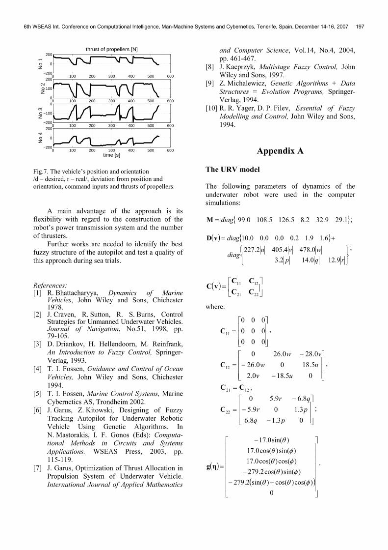
hydrodynamic thrusts.
The desired and real paths, position and
course errors, commands and the thrust of
propellers are shown in Fig. 7. It can be noticed that
a level of the errors is quite small.
7 Conclusions The paper presents a method of control of the
underwater robotic vehicle. In the described
solution using of the fuzzy controllers for the path
following control was proposed. Dynamics of the
propulsion system was regarded by using of both
the affine model of the propeller and the propellers
configuration matrix to determine of thrust
allocation. It makes the algorithms simple and
useful for practical usage.
The nonlinear mathematical model of the real
underwater robot was applied for computer
simulations. The obtained results show the
presented control system enhanced god path
following control in the horizontal plane.
0 10 20 30 40 50 60 700
10
20
30
40
50
60
70
80
90
100position in horizontal plane
x [m]
y [m
]
dr
0 100 200 300 400 500 600−2
−1.5
−1
−0.5
0
0.5
1position error [m]
time [s]
0 100 200 300 400 500 600−100
0
100
200
300
cour
se
orientation (heading) [deg]
dr
0 100 200 300 400 500 600−50
0
50
100
cour
se e
rror
time [s]
0 100 200 300 400 500 600−500
0
500
X [N
]
inputs
0 100 200 300 400 500 600−100
−50
0
50
Y [N
]
0 100 200 300 400 500 600−50
0
50
N [N
m]
time [s]
6th WSEAS Int. Conference on Computational Intelligence, Man-Machine Systems and Cybernetics, Tenerife, Spain, December 14-16, 2007 196
0 100 200 300 400 500 600−200
0
200
No
1
thrust of propellers [N]
0 100 200 300 400 500 6000
100
200
No
2
0 100 200 300 400 500 600−200
−100
0
No
3
0 100 200 300 400 500 600−200
0
200
No
4
time [s]
Fig.7. The vehicle’s position and orientation
/d – desired, r – real/, deviation from position and
orientation, command inputs and thrusts of propellers.
A main advantage of the approach is its
flexibility with regard to the construction of the
robot’s power transmission system and the number
of thrusters.
Further works are needed to identify the best
fuzzy structure of the autopilot and test a quality of
this approach during sea trials.
References: [1] R. Bhattacharyya, Dynamics of Marine
Vehicles, John Wiley and Sons, Chichester 1978.
[2] J. Craven, R. Sutton, R. S. Burns, Control Strategies for Unmanned Underwater Vehicles. Journal of Navigation, No.51, 1998, pp. 79-105.
[3] D. Driankov, H. Hellendoorn, M. Reinfrank,
An Introduction to Fuzzy Control, Springer-
Verlag, 1993.
[4] T. I. Fossen, Guidance and Control of Ocean
Vehicles, John Wiley and Sons, Chichester
1994.
[5] T. I. Fossen, Marine Control Systems, Marine
Cybernetics AS, Trondheim 2002.
[6] J. Garus, Z. Kitowski, Designing of Fuzzy
Tracking Autopilot for Underwater Robotic
Vehicle Using Genetic Algorithms. In
N. Mastorakis, I. F. Gonos (Eds): Computa-
tional Methods in Circuits and Systems
Applications. WSEAS Press, 2003, pp.
115-119.
[7] J. Garus, Optimization of Thrust Allocation in
Propulsion System of Underwater Vehicle.
International Journal of Applied Mathematics
and Computer Science, Vol.14, No.4, 2004,
pp. 461-467.
[8] J. Kacprzyk, Multistage Fuzzy Control, John
Wiley and Sons, 1997.
[9] Z. Michalewicz, Genetic Algorithms + Data
Structures = Evolution Programs, Springer-
Verlag, 1994.
[10] R. R. Yager, D. P. Filev, Essential of Fuzzy
Modelling and Control, John Wiley and Sons,
1994.
Appendix A
The URV model
The following parameters of dynamics of the
underwater robot were used in the computer
simulations:
{ }1.299.322.85.1265.1080.99diag=M ;
( ) { }
+=
rqp
wvudiag
diag
9.120.142.3
0.4784.4052.227
6.19.12.00.00.00.10vD
;
( )
=
2221
1211
CC
CCvC
where:
=
000
000
000
11C ,
−
−
−
=
05.180.2
5.1800.26
0.280.260
12
uv
uw
vw
C ,
1221 CC = ,
−
−
−
=
03.18.6
3.109.5
8.69.50
22
pq
pr
qr
C ;
( )
( )
+−
−
−
=
0
)cos()cos()sin(2.279
)sin()cos(2.279
)cos()cos(0.17
)sin()cos(0.17
)sin(0.17
φθθφθ
φθφθ
θ
ηg.
6th WSEAS Int. Conference on Computational Intelligence, Man-Machine Systems and Cybernetics, Tenerife, Spain, December 14-16, 2007 197