fuzzy logic-based inverse dynamic modelling of robot ... · fuzzy logic-based inverse dynamic...
TRANSCRIPT

FUZZY LOGIC-BASED INVERSE DYNAMIC MODELLING OF ROBOTMANIPULATORS
Meysar Zeinali, Leila NotashDepartment of Mechanical and Materials Engineering, Queen’s University, Kingston, Ontario, Canada
E-mail: [email protected]
Received October 2009, Accepted January 2010
No. 09-CSME-60, E.I.C. Accession 3146
ABSTRACT
This paper presents the design and implementation of a systematic fuzzy modellingmethodology for the inverse dynamic modelling of robot manipulators. The fuzzy logicmodelling methodology is motivated in part by the difficulties encountered in the modelling ofcomplex nonlinear uncertain systems, and by the objective of developing an efficient dynamicmodel for the real-time model-based control. The methodology is applied to build the fuzzylogic-based inverse dynamic model of a prototyped wire-actuated parallel manipulator withuncertain dynamics. The developed inverse dynamics has been used in a fuzzy model-basedadaptive robust controller for the tracking control of the parallel manipulator.
Keywords: manipulator dynamics, fuzzy logic-based modelling, inverse dynamic modelling.
MODELISATION DYNAMIQUE INVERSE DE ROBOTS MANIPULATEURSBASEE SUR LA LOGIQUE FLOUE
RESUME
Dans cet article on presente la conception et l’implantation d’une methode systematique demodelisation par logique floue de la dynamique inverse de manipulateurs robotiques.L’utilisation de la methode de la logique floue est motivee, en partie, par les difficultesrencontrees pour la modelisation de systemes incertains complexes non-lineaires, et par lavolonte de developper un modele dynamique pour la commande en temps reel. Lamethodologie proposee est appliquee a la construction d’un modele base sur la logique flouede la dynamique inverse d’un prototype d’un manipulateur parallele a entraınement par cablesdont la dynamique est incertaine. La dynamique inverse developpee a ete utilisee dans unschema de commande par logique floue base sur un modele, permettant le controle en positiondu manipulateur parallele.
Mots-cles : la dynamique des manipulateurs, modelisation basee sur la logique floue,modelisation de la dynamique inverse.
Transactions of the Canadian Society for Mechanical Engineering, Vol. 34, No. 1, 2010 137
1. INTRODUCTION
Robot manipulators are inherently complex and nonlinear uncertain systems. That is, it is notthat possible to obtain their accurate model due to large dynamic coupling between differentlinks, hard nonlinearity (e.g., Coulomb friction) and time-varying characteristics of themanipulators. To accommodate system uncertainties, variation of the parameters with time anddisturbances; learning, reasoning, decision making and advance modelling techniques should beincorporated in the controller. Very often the approximation capabilities of the fuzzy systemsare used for compensating the unknown dynamics or particular component of the dynamics ofmanipulators. For instance, in [1] a fuzzy system was utilized to compensate for the friction andpayload variation, and in [2] a fuzzy system was used as an adaptive approximator formodelling a manipulator dynamics. Systematic fuzzy modelling of manipulator inverse dynamicmodel from input-output data was presented in [3]. In [4] fuzzy logic was applied for controllinga flexible link robot arm, and in [5] an adaptive neural fuzzy controller was presented formanipulators.
The inverse dynamic model of a robot manipulator is required to generate the control input(i.e., joint torques/forces). In addition, the size of the uncertainties can be reduced, to a largeextent, by having a good dynamic model of the system, which in turn reduces the chattering andhelps to stabilize the closed-loop system. In the following subsections, the general inversedynamic model and fuzzy inverse dynamic model of manipulators are discussed.
1.1. General Inverse Dynamic ModelThe inverse dynamic model of manipulators can be described as
t~M(q)€qqzh q, _qqð Þ ð1Þ
where t~ t1,t2,:::,tn½ �T is the vector of input generalized forces, and n denotes the number ofgeneralized coordinates of the manipulator. Inertia matrix M qð Þ is an n|n symmetric positivedefinite matrix; q~ q1,q2,:::,qn½ �T, _qq~ _qq1, _qq2,:::, _qqn½ �T and €qq~ €qq1,€qq2,:::,€qqn½ �T are the displacement,velocity and acceleration vectors of joints respectively; and
h(q, _qq)~C q, _qqð Þ _qqzff q, _qqð Þzg qð Þzfext ð2Þ
where C q, _qqð Þ is an n|n matrix of centripetal and Coriolis terms, ff is an n|1 vector denotingviscous and Coulomb friction forces, g qð Þ is an n|1 vector of gravitational terms, and fext is ann|1 vector denoting the actuator reaction forces/torques corresponding to the external forces/moments on the end effector. For parallel manipulators, Eq. (2) may contain another term dueto the holonomic constraints because of the closed-loop kinematic chains and existence ofpassive joints, e.g., h q, _qqð Þ~C q, _qqð Þ _qqzff q, _qqð Þzg qð ÞzfextzFT
c l where l is the vector ofLagrange multipliers and FC accounts for the constraint forces induced by the closed-loopkinematic chains [6].
Because of the system uncertainty and external disturbances, Eq. (1), which describes thedynamic model of a manipulator, is not exactly known. Therefore, the dynamic model ofmanipulators is as
t~ MM q,tð ÞzDM q,tð Þ� �
€qqz hh q, _qq,tð ÞzDh q, _qq,tð Þ� �
zd tð Þ ð3Þ
Transactions of the Canadian Society for Mechanical Engineering, Vol. 34, No. 1, 2010 138
where MM q,tð Þ and hh q, _qq,tð Þ are the known (estimated) parts and DM q,tð Þ and Dh q, _qq,tð Þ are theunknown parts of M q,tð Þ and h q, _qq,tð Þ respectively, and d tð Þ is an n|1 bounded vector arisingfrom the external disturbances. Based on Eqs. (1) and (3), the following expression holds
F q, _qq,€qq,tð Þ~FF q, _qq,€qq,tð Þz~FF q, _qq,€qq,tð Þ ð4Þ
where F q, _qq,€qq,tð Þ~M qð Þ€qqzh q, _qqð Þ, FF q, _qq,€qq,tð Þ~MM(q)€qqzhh q, _qqð Þ is the known (approximated) partof the inverse dynamic model and can be approximated using a fuzzy modelling method, and~FF q, _qq,€qq,tð Þ~DM q,tð Þ€qqzDh q, _qq,tð Þzd tð Þ is the uncertainty vector of the inverse dynamic model.
1.2. Fuzzy Inverse Dynamic ModelThe fuzzy dynamic model considered here is a qualitative explanation of the behaviour of
manipulator in the framework of fuzzy logic (in the form of IF-THEN rules) instead of amathematical equation. Conceptually, a multi-input-multi-output (MIMO) system with mul-tiple independent outputs can be considered as a set of multi-input-single-output (MISO)systems [8]. In the inverse dynamic problem of a manipulator, the torque of each joint is afunction of position, velocity and acceleration of that joint and the other joints. Therefore, foran n degrees of freedom (DOF) manipulator, a MISO fuzzy model for joint k (k 5 1, …, n)expresses variation of the torque/force of that joint, as a result of the motion of all joints, in thefollowing form of the rules
Ri : IF q1 is Ai1 AND q2 is Ai2 AND ::: AND qr is Air THEN tk is Bi ð5Þ
where Ri is the i-th rule (i 5 1, …, c), and q1, …, qr are the main input variables for joint k,k51,…, n, that are identified among the elements of the joint displacement, velocity andacceleration vectors. Fuzzy sets Aij (j 5 1, …, r) in the antecedent (IF part) are associated with rinput variables, tk is the output torque of joint k and fuzzy set Bi in the consequent (THENpart) represents the output membership function of rule i.
The four principal components of a fuzzy system with crisp (non-fuzzy) inputs and out-puts are fuzzification, fuzzy rule base, reasoning mechanism (also called fuzzy inference),and defuzzification [9]. The fuzzification refers to replacing the crisp input with a set whoseboundaries are fuzzy, i.e., fuzzy set. As the central part of a fuzzy system, the fuzzy rule base (aset of rules in the form of IF-THEN statements, also referred to as fuzzy model) describes thesystem behaviour. The reasoning mechanism is a decision making logic which employs fuzzyrules from the fuzzy rule base to determine the fuzzy outputs corresponding to the fuzzifiedinputs of the fuzzy system. The process of transforming the fuzzy output of a fuzzy system tonon-fuzzy output (crisp output) is called defuzzification.
The methodology of fuzzy model construction from available input-output data is based onthe improved systematic fuzzy modelling method through the following steps.
1. Generating/finding the optimum number of rules that can describe the behavior of adynamic system accurately and robustly in whole domain of interest.
2. Finding/selecting the minimum number of input variables (referred to as the ‘‘main inputs’’).
3. Designing the antecedent and consequent parts of each rule, which means how to partitionthe input space and output space respectively and how to assign the membership function toeach partition.
4. Designing/selecting the appropriate reasoning mechanism.
Transactions of the Canadian Society for Mechanical Engineering, Vol. 34, No. 1, 2010 139

5. Parameter identification (parameters of the clustering algorithm and parameters of thereasoning mechanism) and parameter tuning procedures.
In the following section, the fuzzy logic-based inverse dynamic model of a wire-actuatedparallel manipulator is developed employing a systematic fuzzy logic modelling. Dataacquisition and preparation is discussed in Section 2.1. The fuzzy model of the manipulatoris presented in Section 2.2. The article concludes with a discussion in Section 3.
2. FUZZY LOGIC-BASED MODELLING OF A WIRE-ACTUATED PARALLELMANIPULATOR
In this paper, the improved systematic fuzzy logic modelling methodology from availableinformation (e.g., a simplified analytical model) and experimental data (input-output data of areal system), proposed in [7], is applied for developing an adaptive fuzzy logic-based inversedynamic model of a 4 DOF wire-actuated parallel manipulator depicted in Fig. 1.
The manipulator has been designed for digging and soil sampling at the planetaryexplorations [10, 11]. The manipulator consists of a constraining linkage with seven joints andsix links (excluding the base link) and three wires. The four degrees of freedom of themanipulator are controlled by five actuators (motors). All motors are 24 V DC servo motorsequipped with gear reducers and encoders. The actuated joints one and two each is coupled withinternal and external planetary gearboxes with a gear reduction of 134 to 1 and 4 to 1respectively. The motion of joints four and five (each equipped with an encoder but no motor)are controlled by three actuated wires; since wires can only pull thus redundant actuation isneeded. The motors of wires one and two are coupled with a gearbox with a gear reduction of12.5 to 1 and the gearbox for wire three has a gear reduction of 45.5 to 1.
To construct the fuzzy inverse dynamic model of the actuated joint/wire i of the manipulator,the input-output data set for that actuated joint/wire need to be formed. The joint/wire torque ti
(output) is proportional to the motor torque tmi of the actuated joint/wire i by its gear ratio NGi
and efficiency of gear transmission gi as ti ~ NGi gi tmi ~ NGi gi KTi im, where KTi and imare respectively the torque constant and current of the motor. The pertinent specifications forthe actuators are reported in [12].
Fig. 1. Wire-actuated parallel robot manipulator.
Transactions of the Canadian Society for Mechanical Engineering, Vol. 34, No. 1, 2010 140
2.1. Data Acquisition and Preparation for Fuzzy ModellingTo construct a fuzzy inverse dynamic model of the parallel manipulator from input-output
data, because the manipulator has five actuators, it can be considered as a composition of fiveMISO subsystems. Each MISO subsystem has one output, i.e., the torque of joint/wire actuator,and 12 input candidates, i.e., the position, velocity and acceleration of the four independentjoints of the constraining linkage (actuated joints one and two and passive joints four and five).Because the configuration of the manipulator can be fully described in terms of the motion ofindependent joints of the constraining linkage [11], instead of the motion of actuated joints/wires, the motion of these four joints are used as inputs.
The first step in data driven modelling (i.e., modelling from input-output data) is to obtain anadequate amount of input-output data by moving the manipulator along different trajectories,and measuring the displacements (and velocities and accelerations) and torques. Since thetest-bed is not equipped with velocity and acceleration sensors, the velocities and accelerationsare calculated using the central difference method as _qq kð Þ~ q kz1ð Þ{q k{1ð Þð Þ=2T and€qq kð Þ~ q kz1ð Þ{2q kð Þzq k{1ð Þð Þ
�T2, where q kð Þ indicates the joint positions at the k-th
sample and T is the sampling period. To have a rich yet small number of identification data(training data) and excite significant number of modes of the manipulator, random trajectoriesand harmonic trajectories with different frequencies and maximum desired amplitudes withinthe manipulator workspace are generated in the Simulink environment. To excite the wires, aswires can only pull, several harmonic and periodic trajectories are generated using the inversekinematic model of the manipulator. It should be noted that when the exciting frequenciescontain low-frequency motion the friction effects become dominant, and when they containhigh-frequency motion the inertial effects are dominant.
Because the first derivative (velocity) and especially the second derivative (acceleration)of positions amplify the high frequency noise, the displacement reading is filtered using thedigital low-pass Butterworth filter (recommended by many researchers) prior to computingthe velocity and acceleration signals. To find a proper cut-off frequency of the filter (to keep theuseful information while rejecting the high frequency components), initially the acceleration of aknown trajectory (e.g., sinusoidal) was compared with the measured and filtered acceleration ofcorresponding known trajectory. Then, since the measured torque of each joint/wire actuatorcontains the effects of accelerations of all joints/wires, based on the power spectral analysis ofthe actuator torques, the cut-off frequency of 35 Hz and 30 Hz were obtained respectively forjoints and wires. Because arbitrary random excitation cannot be applied to wires (wires can onlypull) the 30 Hz cut-off frequency for wires was obtained mostly by trail and error.
The collected data are categorized for three purposes. The main part (about 80%) of the data(training data) is used for structure identification (generating fuzzy IF-THEN rules) thatincludes the output data clustering, main input selection, and input-output membershipassignment. Part of the remaining collected data (tuning data) is used for parameteridentification that includes the weights of fuzzy rules. The remaining data are used for fuzzymodel validation by comparing the output of fuzzy model with the measured torque of joint/wire actuators.
2.2. Fuzzy ModelThe fuzzy logic-based inverse dynamic model of the manipulator is developed according to
the fuzzy modelling algorithm presented in Fig. 2. The parameters and equations referred to inthis flowchart are defined in the following paragraphs. The fuzzy modelling procedure consistsof structure identification and parameter identification.
Transactions of the Canadian Society for Mechanical Engineering, Vol. 34, No. 1, 2010 141

For structure identification, to build the fuzzy model, the output data, i.e., torque of joint/wire actuators, are clustered using the fuzzy c-means algorithm given in [7]. To determine thecorrect number of clusters/rules c (number of groups that exist in the data), i.e., for well-separated and compact clusters, the cluster validity index Sc of [13] is used
Sc~XN
k~1
Xc
i~1uikð Þm xk{vik k2
{ vi{�vvk k2� �
ð6Þ
Fig. 2. Proposed fuzzy modelling flowchart.
Transactions of the Canadian Society for Mechanical Engineering, Vol. 34, No. 1, 2010 142

where N is the number of data vectors, and uik is the membership degree of each data point toeach cluster calculated as
uik ~Xc
j~1
xk{vik kxk{vj
�� �� !(2=m{1)
24
35
{1
ð7Þ
The fuzziness parameter is denoted as m, :k k is the Euclidean norm, xk is the k-th data point,
vi~PN
k~1 uikð Þmxk
.PNk~1 uikð Þm is the cluster centre, and �vv~
Pci~1
PNk~1 uikð Þmxk
.Pci~1
PNk~1 uikð Þm
is the fuzzy total mean vector which represents a weighted mean of data considering theirmembership to each of the clusters in fuzzy partition.
Using the cluster validity analysis, the optimum number of clusters is investigated for eachjoint/wire. As depicted in Fig. 3, for each joint/wire, the smallest number of clusters c after
Fig. 3. Cluster validity indices for the five actuators of manipulator.
Transactions of the Canadian Society for Mechanical Engineering, Vol. 34, No. 1, 2010 143

which there is no considerable change in the minimum value of the validity index is chosen.Then, the main input variables for each joint/wire are identified based on the quantitative pindex that is computed for each joint/wire for the selected number of rules (clusters), c, anddifferent values of the fuzziness parameter, m, as
pj~Pci~1
PCij
max xj
� � ð8Þ
where Cij is the set of inputs xj with uik~1, j 51, 2, …, r0, i 5 1, 2, …, c and k 5 1, 2, …, N, inthe i-th cluster (rule), and r0 is the number of input candidates. Equation (8) is concluded fromthe fact that, in the calculation of the firing strength (antecedent aggregation) vi of the i-th rule,either with the algebraic product operator or with the min operator, the membership degree‘‘one’’ is the neutral element. Therefore, the input variables with many ‘‘one’’ elements in theirmembership function correspond to a large value of p (ineffective inputs), and can be discardedfrom the input candidates. That is, a small value of p represents a more dominant input. Themain input selection results are listed in Table 1; for each column, the highlighted p indicesrepresent the corresponding main inputs of each actuated joint/wire.
To produce the antecedent fuzzy set of each rule, the selected main inputs are partitioned into theappropriate fuzzy sets, using the technique suggested in [13], to form the trapezoidal membershipfunctions for each input. In this method, the membership degree of the peak points (data pointswith membership degree of ‘‘one’’ or close to ‘‘one’’) are the same for the input and output clustersand the membership degree of the remaining data points, e.g., j-th input variable, are calculated as
ujð Þ
ik ~Max
Pcl~1
xjk{vij1
�� ��xjk{vlj
1�� ��
!(1=m{1)24
35{1
,Pcj~1
xjk{vij2
�� ��xjk{vlj
2�� ��
!(1=m{1)24
35{12
435 :xjkvvij
1 or xjkwvij2
1 :vij1v xjkvvij
2
8>>><>>>:
ð9Þ
Transactions of the Canadian Society for Mechanical Engineering, Vol. 34, No. 1, 2010 144
Table 1. Main input indices of actuated joints and wires.
Joint 1c 5 5, m 5 2
Joint 2c 5 5, m 5 2
Wire 1c 5 6, m 5 1.5
Wire 2c 5 5, m 5 1.7
Wire 3c 5 5, m 51.8
pq157.2673e+3 pq15370.7045 pq157.4174e+5 pq155.2432e+4 pq151.0864e+4pq257.9446e+5 pq252.7136e+4 pq254.2255e+7 pq254.3882e+5 pq257.8353e+4pq451.9536e+6 pq459.0021e+3 pq452.1979e+7 pq458.5291e+3 pq452.4266e+3pq551.3341e+7 pq551.0814e+5 pq551.1003e+9 pq556.3028e+8 pq551.5647e+8
p _qq152.4817e+4 p _qq15273.7883 p _qq152.2641e+5 p _qq153.4352e+3 p _qq15 .1642e+3p _qq258.1471e+4 p _qq25499.4337 p _qq258.4342e+6 p _qq255.8215e+3 p _qq251.5393e+3p _qq453.2206e+3 p _qq4510.4070 p _qq459.1016e+3 p _qq453.4641e+3 p _qq451.0945e+3p _qq550.0123 p _qq558.2020e-4 p _qq550.1308 p _qq552.8776e-6 p _qq551.9289e-5
p₠qq1528.3639 p₠qq150.8618 p₠qq15666.5307 p₠qq1572.2085 p₠qq156.0446
p₠qq25287.8772 p₠qq2516.6549 p₠qq255.3404e+3 p₠qq2533.5940 p₠qq256.2398
p₠qq451.0916 p₠qq450.0053 p₠qq452.2590 p₠qq4536.2224 p₠qq456.2522
p₠qq551.3706e-4 p₠qq558.7143e-6 p₠qq550.0012 p₠qq551.4868e-6 p₠qq554.9392e-6

for i 5 1, 2, …, c; j 51, 2, …, r; and k 5 1, 2, …, N; where r is the number of main input variables, xjk
is the k-th data of j-th input variable and vij1 and vij
2 are points on the i-th cluster of j-th axes of inputvariables xj j~1,2, . . . ,rð Þ, which have output membership degrees equal or close to one. At thispoint, the structure of the five MISO fuzzy models of the five actuated joints/wires has been identified.
The defuzzified output value for c fuzzy rules is as:
yy~Xc
i~1Wiy
�i ð10Þ
where the design parameter Wi§0 (i 5 1, 2, …, c) is the weight of the i-th rule that should beidentified such that to minimize the performance index (PI), which is the mean squared error
between the fuzzy model output and the desired/actual output, y�i ~viy0i =Pcj~1
vj which can be
considered as a normalized defuzzified output value of the i-th rule, and yoi is a non-fuzzy
representative of the output fuzzy set Bi of i-th rule and is selected according to the criteriadefined in [14]. To account for the influence of the unmodelled effects (inaccuracies anduncertainties that may exist in the antecedent and consequent fuzzy sets of the rules), in Eq. (10)the parameterized form (weighted sum) of y�i is used.
Following the structure identification, the parameters of the fuzzy model (fuzziness parameterand weights of rules) are calculated for all five joints/wires. The weights of rules are identified inan on-line procedure using a gradient descent technique based on the instantaneous difference ofthe fuzzy model output and actual output, ek~yk{yyk, by minimizing the performance index PI:
PI Wð Þ~PN
k~1 yk{(Pc
i~1 Wiy�i )k
� �2
Nð11Þ
Using the gradient descent technique, the weight modification term for the i-th weight is:
DWi zð Þ~{aLrLPI(W)
LWi
~
2aLr
PNk~1
ezð Þ
k y�i� � zð Þ
k
Nð12Þ
where aLr, 0ƒaLrƒ1, is the learning rate, also called the step size. Therefore, at step z+1 of thelearning process, the updating law for the weight of the i-th rule is obtained as:
Wi zz1ð Þ~Wi zð Þz 2aLr
N
XN
k~1
ezð Þ
k
viy0iPc
j~1
vj
0BBB@
1CCCA
zð Þ
k
0BBBB@
1CCCCA ð13Þ
This parameterized direct fuzzy reasoning adds adaptive capability to a fuzzy model. In areal-time application, the rule weights can be updated at the same sampling rate that the controlloop runs or at the sampling rate slower than the sampling rate of control loop (to reduce thecomputation burden). The rule weights are factors by which the contribution of each rule in therule set are multiplied with as a fuzzy system adapts to its environment.
The fuzziness parameter m is identified by plotting the performance index PI versus m(Fig. 4). With proper selection of m, the behaviour of the cluster validity index can be improved
Transactions of the Canadian Society for Mechanical Engineering, Vol. 34, No. 1, 2010 145

during iteration as depicted in the flowchart of Fig. 2. In addition, by proper identification of m,there is no need to adjust the membership functions of input and output data. The results forthe two joints and three wires are summarized in Table 2. The fuzzy logic inverse dynamicmodels of the five actuated joints/wires of manipulator are depicted in Fig. 5.
Fig. 4. Performance index variation with the fuzziness parameter m for actuated joints/wires.
Transactions of the Canadian Society for Mechanical Engineering, Vol. 34, No. 1, 2010 146
Table 2. Specification of the fuzzy model of actuated joints/wires.
Joints/Wires# of Clusters c
(Fig. 3)Fuzziness Parameter m
(Fig. 4)Main Input Variables
(Table 2)
Joint 1 5 2 _qq5,₠qq
1,₠qq
2,₠qq
4,₠qq
5
Joint 2 5 2 _qq4, _qq
5,₠qq
1,₠qq
4,₠qq
5
Wire 1 6 1.5 _qq5,₠qq
1,₠qq
2,₠qq
4,₠qq
5
Wire 2 5 1.7 _qq5,₠qq
1,₠qq
2,₠qq
4,₠qq
5
Wire 3 5 1.8 _qq5,₠qq
1,₠qq
2,₠qq
4,₠qq
5
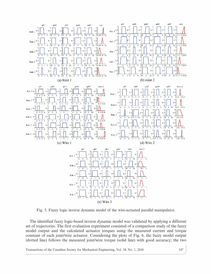
The identified fuzzy logic-based inverse dynamic model was validated by applying a differentset of trajectories. The first evaluation experiment consisted of a comparison study of the fuzzymodel output and the calculated actuator torques using the measured current and torqueconstant of each joint/wire actuator. Considering the plots of Fig. 6, the fuzzy model output(dotted line) follows the measured joint/wire torque (solid line) with good accuracy; the two
Fig. 5. Fuzzy logic inverse dynamic model of the wire-actuated parallel manipulator.
Transactions of the Canadian Society for Mechanical Engineering, Vol. 34, No. 1, 2010 147

Fig. 6. Comparison of the actuated joint/wire torque computed by fuzzy model (dotted line) with themeasured joint/wire torque (solid line) for the sinusoidal and periodic trajectories.
Transactions of the Canadian Society for Mechanical Engineering, Vol. 34, No. 1, 2010 148
lines are overlapped in most parts of the plots. In the second step, the effectiveness of theidentified fuzzy model was assessed through the use of the fuzzy model as a model-basedcomponent of the control methodology of [15] for the trajectory tracking task. Theexperimental results verified that, in the controller, the main part of the control input wasproduced by the fuzzy inverse dynamic model of the system, i.e., the controller mainly relied onthe model-based component rather than the error-based component.
3. DISCUSSION AND CONCLUSIONS
In this paper, a methodology for the development of the fuzzy logic-based inverse dynamicmodel of robot manipulators was presented. The methodology was implemented to build anadaptive fuzzy model of a prototyped 4 DOF wire-actuated parallel manipulator which employshybrid actuation of wires and joints. The methodology for fuzzy model construction includesthe input-output data collection, system identification (structure identification and parameteridentification), and fuzzy reasoning. For the structure and parameter identification, the rulegeneration (clustering of data) and main input selection, as well as identification of fuzzinessparameter and weight of rules were discussed. The optimum value of the fuzziness parameter mwas identified using the variation of the performance index with m. This is justified by using theconcept of the interval of confidence [16], which relates parameter m to the level of uncertaintycontained in the input-output data [12]. The optimum number of clusters (rules) was chosenbased on an additional criterion using the variation of the fuzzy model output with respect tothe number of clusters. A generalized and parameterized reasoning mechanism, constructedbased on the weighted sum of the normalized defuzzified output value of each individual rule,was applied. To relax the persistent excitation condition (condition on the input signal thatguarantees uniform asymptotic convergence of the identification algorithms) in the off-lineidentification procedure and to account for the effects of the time-varying parameters, agradient-descent based parameter adjustment was implemented to tune the parameters ofreasoning mechanism instead of the existing heuristic parameter identification. The identifiedfuzzy model (calculated actuator torques) of the manipulator was verified by the correspondingmeasured quantities; the fuzzy model output matched the measured joint/wire torques.
REFERENCES
1. Yoo, B.K. and Ham, W.C., ‘‘Adaptive control of robot manipulators using fuzzy compensator,Part I,’’ Proceedings of IEEE Conf. on Intelligent Robots and Systems, Vol. 1, pp. 35–40, 1999.
2. Fc, S., Zq, S. and G, F., ‘‘Design of adaptive fuzzy sliding mode controller for robotmanipulators,’’ Proceedings of IEEE Conf. on Fuzzy Systems, Vol. 1, pp. 62–67, 1996.
3. Emami, M.R., Goldenberg, A.A. and Turksen, I.B., ‘‘Fuzzy-logic control of dynamic systems:from modeling to design,’’ Engineering Application of Artificial Intelligence, Vol. 13, pp. 47–6900,2000.
4. Lin, J. and Lewise, F., ‘‘Fuzzy controller for flexible-link robot arm by reduced-ordertechniques,’’ Proceedings of IEE Control Theory and Applications, Vol. 149, No. 3, pp. 177–187,2002.
5. Zeinali, M. and Notash, L., ‘‘Robust adaptive neural fuzzy controller with model uncertaintyestimator for manipulators,’’ Transactions of the Canadian Society for Mechanical Engineering,Vol. 28, No. 2A, pp. 197–219, 2004.
6. Angeles, J., Fundamental of Robotic Mechanical Systems, Theory, Methods, and Algorithms, 2ndEdition, Springer, 2003.
Transactions of the Canadian Society for Mechanical Engineering, Vol. 34, No. 1, 2010 149

7. Zeinali, M. and Notash, L., ‘‘A systematic method of adaptive fuzzy logic modeling using animproved fuzzy c-means clustering algorithm for rule generation,’’ Proceedings of IEEE Conf.Control Applications, pp. 84–89, 2005.
8. Sugeno, M. and Yasukawa, T., ‘‘A fuzzy logic based approach to qualitative modelling,’’ IEEE
Transactions Fuzzy Systems, Vol. 1, pp. 7–3, 1993.9. Jang, J.S.R., Sun, C.T. and Mizutani, E., Neuro-Fuzzy and Soft Computing, Prentice-Hall, 1997.
10. Mroz, G. and Notash, L., ‘‘Design and prototype of parallel, wire-actuated robots with aconstraining linkage,’’ Journal of Robotic Systems, Vol. 21, No. 12, pp. 677–687, 2004.
11. Sahin, S. and Notash, L., ‘‘Kinematic modelling and analysis of a wire-actuated parallelmanipulator,’’ Proceedings of 4th CCToMM Symposium on Mechanisms, Machines and
Mechatronics, 12 pages, 2007.12. Zeinali, M., Fuzzy Model-Based Adaptive Robust Control Design and Application to Robot
Manipulators, Ph.D. Dissertation, Department of Mechanical and Materials Engineering,Queen’s University, 2007.
13. Emami, M.R., Turksen, I.B. and Goldenberg, A.A., ‘‘Development of a systematicmethodology of fuzzy logic modelling,’’ IEEE Transactions on Fuzzy Systems, Vol. 6, No. 3,pp. 346–361, 1998.
14. Wang, L. and Mendel, J.M., ‘‘Generating fuzzy rules by learning from examples,’’ IEEETransactions on Systems, Man and Cybernetics, Vol. 22, pp. 1414–1427, 1992.
15. Zeinali, M. and Notash, L., ‘‘Fuzzy logic-based adaptive robust control for parallelmanipulators,’’ Proceedings of 12th World Congress in Mechanism and Machine Science, 6 pages,2007.
16. Zak, H.S., Systems and Control, Oxford University Press, 2003.
Transactions of the Canadian Society for Mechanical Engineering, Vol. 34, No. 1, 2010 150