fuzzy logic control for sfb active queue management ... - eudl
TRANSCRIPT

Fuzzy Logic Control for SFB Active QueueManagement Mechanism
Nguyen Kim Quoc1(&), Vo Thanh Tu2, and Nguyen Thuc Hai3
1 Faculty of IT, Nguyen Tat Thanh University, Ho Chi Minh, [email protected]
2 Faculty of IT, Hue University of Science, Hue, [email protected]
3 Institute of IT, Ha Noi University of Technology, Hanoi, [email protected]
Abstract. Internet is growing not only in the number of connected devices butalso the diversity of the application layers. Therefore, the bottleneck problem inthe router is a pressing issue in congestion control. So using the mechanisms ofactive queue management for congestion control at routers is playing animportant role for the reliable and effective Internet network operation for users.Mechanism of active queue management SFB works well in the router, but nothighly effective. Therefore, we propose to incorporate intelligent computationthrough fuzzy logic control system into the mechanism SFB which can operatemore efficiently to improve service quality and network performance.
Keywords: Congestion control � Active queue management � Fuzzy logiccontroller
1 Introduction
Engineering active queue management (AQM: Active Queue Management) ismechanism controlling queue and loading operations at the routers. AQM controls thenumber of packets in the router queues by scheduling, removing proactively a comingpacket or notifying blockage to regulate traffic on the network [2, 4, 5, 12]. In recentyears, researchers have proposed a number of queue management mechanisms inrouters based on the size of the queue (such as RED…) [19], packet loss factor andperformance airtime usage (such as BLUE…)[7–9]. However, these mechanisms donot ensure good fairness for flows [6, 11, 22]. The mechanism SFB (Stochastic FairBLUE) activities based on BLUE mechanisms ensure fairness for the flows, but do notachieve high throughput, haven’t got low packet loss rate and small queue used spaceyet, so latency is still high [24]. Therefore, in this paper we propose to make activequeue management mechanism FSFB (Fuzzy SFB) by using fuzzy logic controller(FLC) integrated active queue management mechanism SFB to proactively detect andcontrol congestion better [10].
The results of the analysis and evaluation of simulation experiments based on NS2software [13, 18] installed show that: queue management mechanism FSFB activelyworks well at each router, reduces packet drop and the latency and increases
P.C. Vinh et al. (Eds.): ICCASA 2013, LNICST 128, pp. 102–114, 2014.DOI: 10.1007/978-3-319-05939-6_11, � Springer International Publishing Switzerland 2014

throughput of the flows. Therefore, the new queue management mechanism FSFB hasimproved network performance and responded quickly to the changes of networktraffic of packets on the transmission line, so the quality of network services enhanced.
This article consists of five parts. The first part points out the necessity of queuemanagement and proposed idea of new queue management mechanism FSFB. Thesecond part discuses new queue management mechanism FSFB and relating issues.The third part focuses on the new queue management FSFB of the authors. The fourthpart shows the process of simulation installation, test of experimental results with theprocess of theoretical study. The last part compares the performance of proposedqueue management mechanism with the current queue management mechanism tomake judgments and conclusions.
2 Related Works
2.1 Operation of SFB Mechanism
SFB divided queue into calculation bins, each bucket maintains a packet markingprobability pm. This probability increased /decreased linearly depending on the packetdrop rate or extent of use of the transmission line. If at queue, there is a continu-ousness of packet cancellation because large transduction overflows queue, it willincrease pm, increases severity of obstructive message that it will sends back to thesource. Conversely, if the queue becomes empty due to weak transduce or idletransmission line, then packet marking probability pm reduces. Packet markingprobability of each bin is determined as follows [23, 24]:
Based on the packet loss: if ((now-last_update) [ freeze_time) then
pm ¼ pm þ d1 and Last update ¼ now ð1Þ
Based on the idle connection: if ((now-last_update) [ freeze_time) then
pm ¼ pm�d2 and Last update ¼ now ð2Þ
Where, pm packet marking probability, d1 the increasing amount of pm, d2 thereducing amount of pm, now current time, last_update last time when pm changed,freeze_time amount of time between successful changes.
The bins are organized in L levels, each level has N bins. In addition, SFB uses Lindependent hash functions, each function corresponding to a level. Each hashfunction maps a flow into one of the coming bins at this level. The bins are used totrack and capture the statistics of queue occupation of the packet in that bin. When apacket comes to queue, it is hashed into L bins, each level is a bin. If the number ofpackets mapped in a bin exceeds a certain threshold (e.g., the size of the bin), theprobability pm in that bin increases. If the number of packets in the bin is reduced untilthe end, pm reduces. Figure 1 below shows the operation model of the active queuemanagement mechanism SFB:
Fuzzy Logic Control for SFB Active Queue Management Mechanism 103

Observation shows that with an unresponsive flow hashed into L bins, probabilitypm at the bins rapidly rises to 1. The responsive flows can share one or two bins withunresponsive flows. However, if the number of unresponsive flows is not too large ascompared to the number of bins, the responsive flow is able to be hashed at least intoone bin without unresponsive flow, thus there is normal value pm. The markingdecision of a package based on pmin that is the minimum value of pm of the mappedbins. If pmin is 1, the packet is defined as unresponsive flow and limited transmissionspeed of flow.
Here, the flows are defined as limited and unresponsive flows to save bandwidth.This strategy is done by limiting the speed of packet flowing in queue for flows withpmin value of 1. Picture above is an example that shows how SFB works. An unre-sponsive flow mapped into the bins, marking probability in these bins is 1. While TCPflows can be mapped into the same bin with the unresponsive flows at a particularlevel, it can also be mapped into the bins at other levels. Thus, the lowest markingprobability of TCP flows is less than 1, so it is not defined as unresponsive flows. Onthe other hand, when the marking probability of unresponsive flows is 1, it will belimited transmission speed.
2.2 Effect of Boxtime Parameter
In SFB, all unresponsive flows are processed as a whole. How many the bandwidthused for the unresponsive flows has? It depends on the key parameter Boxtime.Boxtime is the interval without packet of such unresponsive flow coming into thequeue. When a packet of UDP flow comes, if it is detected as packet of unresponsiveflow, SFB will compare the current time with the nearest time when a packet of anyunresponsive flow comes to the queue. If the period of these two events is greater thanBoxtime, the packet will be in the queue, otherwise it will fall. If it is in the queue, thecurrent time is updated for the next comparison. By this way, Boxtime indirectlycontrols how bandwidth is used for unresponsive flows. The large parameter Boxtime
Fig. 1. The operation model of the mechanism SFB
104 N.K. Quoc et al.

means that unresponsive flows can only achieve a low throughput, average queuelength of the UDP flows is small. Conversely, if the value of Boxtime is small, theaverage queue size of the UDP flow is large. It is reasonable when the value of smallBoxtime results throughput for large unresponsive flows. From the Boxtime is a staticparameter, it can only be set by hand and hard to configure automatic adaptation,Boxtime value in a case cannot be applied to other case. This is a main drawback ofSFB that should be addressed.
To improve fairness among UDP flows, we propose a method to create Boxtime asa random bit. By this way, the fairness among UDP flows is improved. However, thismethod only improves the fairness of unresponsive flows when they are limited thespeed to create stability of bandwidth through the bottleneck transmission line. Thehigh bandwidth streams will have higher mark probability as compared to the lowbandwidth streams.
2.3 SFB Algorithm
Step 1: Calculate the hash functions (h0, h1,.., hL-1).Step 2: Check at each level. If the bin size is larger than allowed limit, then goes
through Step 3. Conversely, if the bin is empty, goes through Step 4, if notgoes through Step 5.
Step 3: Check if the interval from last update of the bin to the present time is greaterthan the allowed threshold, the increase of packet dropping probability (p)appears, goes through Step 5.
Step 4: Check if the interval from last update of the bin to the present time is less thanthe allowed threshold, the reduction of packet dropping probability (p)appears, goes through Step 5.
Step 5: Check if the smallest probability at the bins of packets mapped is of 1, thetransmission speed of the flows is limited, in contrast coming packet ismarked with probability p. Figure 2 shows the SFB algorithm.
3 Proposed Fuzzy Approach
3.1 Fuzzy Logic Controller
Fuzzy logic controllers, such as expert systems, can be used to model human expe-riences and decision making human behavior. FLC in the input-output relationship isexpressed by using a set of linguistic rules or relational expressions. A FLC basicallyconsists of four important parts including a fuzzifier, a defuzzifier, an inference engineand a rule base. In many fuzzy control applications, the input data are often clear,therefore, a fuzzification is necessary to convert the input crisp data into an appro-priate value set with linguistic that is needed in inference engine. Singleton fuzzifier isthe general fuzzification method used to map the crisp input to a singleton fuzzy set. Inthe rule base of a FLC, a set of fuzzy control rules, which characterizes the dynamicbehavior of system, is defined. The inference engine is used to form inferences anddraw conclusions from the fuzzy control rules. Figure 3 shows the fuzzy logic
Fuzzy Logic Control for SFB Active Queue Management Mechanism 105

controller architecture. The output of inference engine is sent to defuzzification unit.Defuzzification is a mapping from a space of fuzzy control actions into a space of crispcontrol actions [26].
Suppose the FLC has n input variables x1, x2,.., xn. Furthermore, suppose the rulebase consists of K rules with the following general form: IF (x1 is A1)^…^ (xi is Ai)^…^(xn is An) THEN y is B. Where in the Ai and B are fuzzy sets of linguisticvariables x1, x2,.., xn and y respectively. The output function f(X) of this fuzzy con-troller with singleton fuzzifier, inference engine of result and center-average de-fuzzification method can be calculated as follows:
Fig. 2. Flowchart of algorithm of SFB mechanism
106 N.K. Quoc et al.

f xð Þ ¼Pk
j¼1 y j0 �Qn
i¼1 l ji xið Þ
Pkj¼1
Qni¼1 l j
i xið Þð3Þ
Where y0 is the center value of the output fuzzy set b, l (x) is the membershipfunction for fuzzy sets. In our proposed model, we use two input variables for fuzzycontroller which shows the current congestion including the packet loss rate andcurrent queue length and the output will be the packet making probability value.
Fig. 3. Architecture of fuzzy inference system
Fig. 4. Membership function of packet loss rate
Fig. 5. Member function of level of using the size of the queue
Fuzzy Logic Control for SFB Active Queue Management Mechanism 107

3.2 Linguistic Variables and Membership Functions
Input linguistic variables are variables representing the main affecting factors on theoperation mechanism SFB. Here, we select packet loss factor, level of queue use tomake input linguistic variables and the probability of packet loss used as outputlinguistic variables. Because the method of fuzzy triangular /trapezoidal is simple andeffective noise reduction, so we choose this method to construct the membershipfunction for the linguistic variable input and output (Figs. 4, 5, 6).
3.3 Construction of Fuzzy Rules
The fuzzy IF-THEN rules are built on experience from the experimental results andthe value of the membership functions of the linguistic variables. There are twoapproaching methods: trial and error approaching method based on the knowledgegained from the experiment, a set of rule base based on IF-THEN rules and thensystem is tested. If the experimental results are deduced from the unsatisfactory laws,the laws will be amended. This process is continued until the function of the controlleris satisfied. Based on functions of experiment and theory, we build rules in the rulebase as follows:
Fig. 6. Membership function of packet loss probability
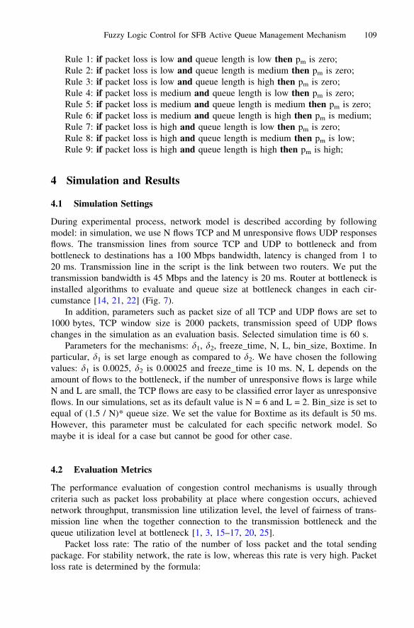
Fig. 7. Network simulation model
108 N.K. Quoc et al.
Rule 1: if packet loss is low and queue length is low then pm is zero;Rule 2: if packet loss is low and queue length is medium then pm is zero;Rule 3: if packet loss is low and queue length is high then pm is zero;Rule 4: if packet loss is medium and queue length is low then pm is zero;Rule 5: if packet loss is medium and queue length is medium then pm is zero;Rule 6: if packet loss is medium and queue length is high then pm is medium;Rule 7: if packet loss is high and queue length is low then pm is zero;Rule 8: if packet loss is high and queue length is medium then pm is low;Rule 9: if packet loss is high and queue length is high then pm is high;
4 Simulation and Results
4.1 Simulation Settings
During experimental process, network model is described according by followingmodel: in simulation, we use N flows TCP and M unresponsive flows UDP responsesflows. The transmission lines from source TCP and UDP to bottleneck and frombottleneck to destinations has a 100 Mbps bandwidth, latency is changed from 1 to20 ms. Transmission line in the script is the link between two routers. We put thetransmission bandwidth is 45 Mbps and the latency is 20 ms. Router at bottleneck isinstalled algorithms to evaluate and queue size at bottleneck changes in each cir-cumstance [14, 21, 22] (Fig. 7).
In addition, parameters such as packet size of all TCP and UDP flows are set to1000 bytes, TCP window size is 2000 packets, transmission speed of UDP flowschanges in the simulation as an evaluation basis. Selected simulation time is 60 s.
Parameters for the mechanisms: d1, d2, freeze_time, N, L, bin_size, Boxtime. Inparticular, d1 is set large enough as compared to d2. We have chosen the followingvalues: d1 is 0.0025, d2 is 0.00025 and freeze_time is 10 ms. N, L depends on theamount of flows to the bottleneck, if the number of unresponsive flows is large whileN and L are small, the TCP flows are easy to be classified error layer as unresponsiveflows. In our simulations, set as its default value is N = 6 and L = 2. Bin_size is set toequal of (1.5 / N)* queue size. We set the value for Boxtime as its default is 50 ms.However, this parameter must be calculated for each specific network model. Somaybe it is ideal for a case but cannot be good for other case.
4.2 Evaluation Metrics
The performance evaluation of congestion control mechanisms is usually throughcriteria such as packet loss probability at place where congestion occurs, achievednetwork throughput, transmission line utilization level, the level of fairness of trans-mission line when the together connection to the transmission bottleneck and thequeue utilization level at bottleneck [1, 3, 15–17, 20, 25].
Packet loss rate: The ratio of the number of loss packet and the total sendingpackage. For stability network, the rate is low, whereas this rate is very high. Packetloss rate is determined by the formula:
Fuzzy Logic Control for SFB Active Queue Management Mechanism 109

packet loss percentage ¼PN
i¼1 packet lossPN
1 packet sentð4Þ
Transmission line utilization level: As the ability to take advantage of networktraffic that said the index’s ability to communicate through the network connection isstrong or weak and is calculated by the following formula:
utilization ¼ byte departurest
bandwidth� tð5Þ
Where utilization is the level of using transmission lines, byte_departurest is thenumber of bytes transmitted in t seconds, the bandwidth is the bandwidth of thetransmission line and t is time of transmission.
Fairness level: is level of flows in network with ensuring fairness of connectionswhen network has many other throughput types. Level of fairness is 1 whenthroughput of flows is equal, unless when throughput of flows is unequal, this value isless than 1. This value demonstrates greater, assurance of the congestion controlalgorithms is well. Fairness level is calculated as following formula:
fairness ¼ ðPN
i¼1 xiÞ2
N �PN
i¼1 x2i
ð6Þ
In particular, Fairness is fair level of flows, Fairness [ [0, 1], xi: is the throughputof flow i and N is the number of flows.
Average Queue Size: The index indicates directly the level of resource use atrouter. This index is defined as the ratio of the average queue size to the actual size ofthe queue. Mechanism with this small ratio will have small latency at the queue andrisk of overflew queue is low. In contrast, the mechanism will make large latency andhigh risk of overflew queue. We use the quadratic average of control deviation to beindex of queue utilization level and it is defined as:
Se ¼ffiffiffiffiffiffiffiffiffiffiffiffiffi
1M þ 1
rXM
i¼0
e2i ¼
ffiffiffiffiffiffiffiffiffiffiffiffiffiffiffiffiffiffiffiffiffiffiffiffiffiffiffiffiffiffiffiffiffiffiffiffiffiffiffiffiffiffiffiffiffiffi
1M þ 1
XM
i¼0
Qi � Qref
� �2
vuut ð7Þ
In particular, Qref is the queue size, Qi is the queue size at the ith sampling timeand M is the number of samples.
4.3 Evaluation of Packet Loss Rate
From the graph Fig. 8, we see that the queue size in the router increases, the packetloss rate of mechanisms reduces and when the number of connections to the routerincreases, the packet loss rate increases. In all cases, SFB always has the highestpacket loss rate and the FSFB always have the lowest packet loss, when the queue sizeof 400 or more and the number of connections is less than 100, the packet loss rate ofFSFB less than 2.5 %.
110 N.K. Quoc et al.

4.4 Evaluation of Transmission Utilization Level
The graph in Fig. 9 shows the level of transmission line utilization of the mechanisms.The ability to take advantage of the transmission line utilization of the mechanismsincreases, when the queue size and loading (number of connection flows) increases.When the queue size from 400 and over or the number of connections into router from100 and over, mechanism FSFB uses better of transmission line, transmission rateused is over 90 %, and is always higher than the mechanism SFB.
4.5 Evaluation of Fairness
Based on the graph of Fig. 10 shows the fairness of the algorithm, we found that thefairness level of the algorithm by SFB and FSFB is very high at over 80 % for allcases. Particularly, mechanism FSFB always balance over 90 % in the cases whichthere are the changed number of connection flows.
Fig. 8. Packet loss rate of the mechanisms of active queue management
Fig. 9. The usage level of the transmission line of mechanisms of active queue management
Fuzzy Logic Control for SFB Active Queue Management Mechanism 111

4.6 Evaluation of medium queue size
Based on the simulation results and graph demonstrating usage rate of the queue sizeof algorithm in Fig. 11, we found that FSFB usage level is always lower than SFB, incases of the changing queue size, this figure is less than 40 %, and less than 60 % forall cases having changed flows. This matter makes the latency and the ability tooverflow queue at routers of low mechanism FSFB.
5 Conclusion
Internet facing boom in connectivity, applications and services based on it. Thecongestion control by mechanisms of the active queue management in routers isessential. However, putting intelligent computing factors, fuzzy control into mecha-nisms of the active queue management, so these mechanisms operate more efficient, toimprove quality of service and network performance. In this paper, we have changedthe mechanism SFB of queue management by introducing fuzzy logic controllersinvolved in the process of calculating the probability of packet mark based on thelevel of packet loss and queue use level at the router. Experimental simulation based
Fig. 10. The balance of the mechanism of active queue management
Fig. 11. The usage of the active queue management mechanisms
112 N.K. Quoc et al.

on software NS2 to the traditional mechanisms SFB and SFB with fuzzy controller(FSFB) in the same network model, showed FSFB has low packet loss rate, the use ofhigh transmission and small latency at router queue. So FSFB controls and conductscongestion control better than the FSB. Results of the study group would contribute tothe study of the world to improve network performance, enhance network quality ofservice.
References
1. Kapadia, A., Feng, W., Campbell, R.H.: GREEN: a TCP equation-based approach to activequeue management. U.S Department of Energy through Los Alamos National Laboratorycontract W-7045-ENG-36 (2011)
2. Dana, A., Malekloo, A.: Performance comparison between active and passive queuemanagement. Int. J. Comput. Sci. Issues (IJCSI) 7(3) No 5, 13–17 (2010)
3. Bitorika, A., Robin, M., Huggard, M., Goldrick, M.: A Comparative Study of Active QueueManagement Schemes. Department of Computer Science Trinity College, Dublin (2011)
4. Wydrowski, B.P.: Techniques in Internet Congestion Control. Electrical and ElectronicEngineering Department, The University of Melbourne (2003)
5. Wydrowski, B., Zukerman, M.: GREEN: an active queue management algorithm for a self.ARC Special Research Centre for Ultra-Broadband Information Networks, EEEDepartment, The University of Melbourne, Parkville, Vic. 3010, Australia (2010)
6. Ali Ahammed, G.F., Banu, R.: Analyzing the performance of active queue managementalgorithms. Int. J. Comput. Netw. Commun. (IJCNC) 2(2), 1–19 (2010)
7. Thiruchelvi, G., Raja, J.: A survey on active queue management mechanisms. Int.J. Comput. Sci. Netw. Secur. (IJCSNS) 8(12), 130–145 (2008)
8. Hasegawa, G., Murata, M.: Analysis of dynamic behaviors of many TCP connectionssharing tail-drop – RED. CybermediaCenter, Osaka University, Japan (2003)
9. Chandra, H., Agarwal, A., Velmurugan, T.: Analysis of active queue managementalgorithms & their implementation for TCP/IP networks using OPNET simulation tool. Int.J. Computer Appl. (0975 – 8887) 6(11), 12–15 (2010)
10. Tabash, I.K., Mamun, M.A.A., Negi, A.: A fuzzy logic based network congestion controlusing active queue management techniques. J. Sci. Res. 2(2), 273–284 (2010)
11. Chung, J., Claypool, M.: Analysis of active queue management. Computer ScienceDepartment Worcester Polytechnic Institute Worcester, MA 01609, USA (2008)
12. Chitra, K., Padamavathi, G.: Classification and performance of AQM-based schemes forcongestion avoidance. Int. J. Comput. Sci. Inform. Secur. (IJCSIS) 8(1), 331–340 (2010)
13. Fall, K., Varadhan, K.: The ns Manual, A Collaboration between researchers at UCBerkeley, LBL, USC/ISI, and Xerox PARC (2010)
14. Le, L., Jeffay, K., Donelson Smith, F.: A loss and queuing-delay controller for router buffermanagement. In: Proceedings of the 26th IEEE International Conference on DistributedComputing Systems (ICDCS’06) (2006)
15. Le, L., Aikat, J., Jeffay, K., Donelson Smith, F.: The effects of active queue managementand explicit congestion notification on web performance. IEEE/ACM Trans. Netw. 15(6),1217–1230 (2007)
16. Kwon, M., Fahmy, S.: A comparison of load-based and queue-based active queuemanagement algorithms. Department Of computer Science, Purdue University, WestLafayette, IN 47906-1398, USA (2010)
Fuzzy Logic Control for SFB Active Queue Management Mechanism 113

17. Soyturk, M., Design and Analysis of TCP/IP Networks. G.Y.T.E., Spring (2011)18. Ns-2.: Network Simulator. http://www.isi.edu/nsnam/ns19. Floyd, S., Jacobson, V.: Random early detection gateways for congestion avoidance.
Lawrence Berkeley Laboratory, University of California (1993)20. Athuraliya, S., Low, S.H., Li, V.H., Yin, Q.: REM active queue management. IEEE Netw.
15(3), 48–53 (2001)21. Ahmad, S., Mustafa, A., Ahmad, B., Bano, A., Hosam, A.A.: Comparative study of
congestion control techniques in high speed networks. IJCSIS 6(2), 222–231 (2009)22. Bhaskar Reddy, T., Ahammed, A., Banu, R.: Performance comparison of active queue
management techniques. IJCSNS Int. J. Comput. Sci. Netw. Secur. 9(2), 405–408 (2009)23. Feng, W., Kandlurz, D.D., Sahaz, D., Shin, K.G.: BLUE-a new class of active queue
management algorithms. Department of EECS Network Systems, University of Michigan(2009)
24. Feng, W., et al.: Stochastic fair blue: a queue management algorithm for enforcing fairness.In: Proceedings of IEEE, April 2001
25. Stallings, W.: High-Speed Network: TCP/IP and ATM Design Principles. Prentice Hall,Upper Saddle River (1998). ISBN 0-13-525965
26. Zadeh, L.A.: Fuzzy sets. Inf. Control 8, 333–353 (1965)
114 N.K. Quoc et al.