fxfq-p ceiling mounted cassette type (round flow) · 7.2 octave band level ... return air...
TRANSCRIPT

EDUS391000 - F1
AMERICAS
FXFQ-PCeiling Mounted Cassette Type
(Round Flow)
EDUS391000-F1
FXFQ-P 1
FXFQ-PCeiling Mounted Cassette Type
(Round Flow)
1.Specifications ...................................................................... 22.Dimensions.......................................................................... 43.Piping Diagrams .................................................................. 74.Wiring Diagrams .................................................................. 85.Electric Characteristics ........................................................ 96.Capacity Tables................................................................. 10
6.1 Cooling Capacity ..................................................................106.2 Heating Capacity ..................................................................11
7.Sound Levels (Reference)................................................. 127.1 Overall ..................................................................................127.2 Octave Band Level ...............................................................12
8.Center of Gravity ............................................................... 149.Installation ......................................................................... 1510.Accessories ..................................................................... 41
Specifications EDUS391000-F1
1. Specifications
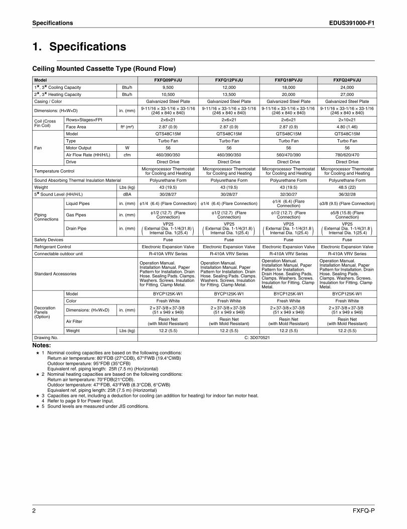
Ceiling Mounted Cassette Type (Round Flow)
Notes: 1 Nominal cooling capacities are based on the following conditions:
Return air temperature: 80°FDB (27°CDB), 67°FWB (19.4°CWB)Outdoor temperature: 95°FDB (35°CFB)Equivalent ref. piping length: 25ft (7.5 m) (Horizontal)
2 Nominal heating capacities are based on the following conditions:Return air temperature: 70°FDB(21°CDB). Outdoor temperature: 47°FDB, 43°FWB (8.3°CDB, 6°CWB)Equivalent ref. piping length: 25ft (7.5 m) (Horizontal)
3 Capacities are net, including a deduction for cooling (an addition for heating) for indoor fan motor heat.4 Refer to page 9 for Power Input.
5 Sound levels are measured under JIS conditions.
Model FXFQ09PVJU FXFQ12PVJU FXFQ18PVJU FXFQ24PVJU
1, 3 Cooling Capacity Btu/h 9,500 12,000 18,000 24,000
2, 3 Heating Capacity Btu/h 10,500 13,500 20,000 27,000
Casing / Color Galvanized Steel Plate Galvanized Steel Plate Galvanized Steel Plate Galvanized Steel Plate
Dimensions: (H×W×D) in. (mm) 9-11/16 × 33-1/16 × 33-1/16 (246 x 840 x 840)
9-11/16 × 33-1/16 × 33-1/16 (246 x 840 x 840)
9-11/16 × 33-1/16 × 33-1/16 (246 x 840 x 840)
9-11/16 × 33-1/16 × 33-1/16 (246 x 840 x 840)
Coil (Cross Fin Coil)
Rows×Stages×FPI 2×6×21 2×6×21 2×6×21 2×10×21
Face Area ft² (m²) 2.87 (0.9) 2.87 (0.9) 2.87 (0.9) 4.80 (1.46)
Fan
Model QTS48C15M QTS48C15M QTS48C15M QTS48C15M
Type Turbo Fan Turbo Fan Turbo Fan Turbo Fan
Motor Output W 56 56 56 56
Air Flow Rate (HH/H/L) cfm 460/390/350 460/390/350 560/470/390 780/620/470
Drive Direct Drive Direct Drive Direct Drive Direct Drive
Temperature Control Microprocessor Thermostatfor Cooling and Heating
Microprocessor Thermostatfor Cooling and Heating
Microprocessor Thermostatfor Cooling and Heating
Microprocessor Thermostatfor Cooling and Heating
Sound Absorbing Thermal Insulation Material Polyurethane Form Polyurethane Form Polyurethane Form Polyurethane Form
Weight Lbs (kg) 43 (19.5) 43 (19.5) 43 (19.5) 48.5 (22)
5 Sound Level (HH/H/L) dBA 30/28/27 30/28/27 32/30/27 36/32/28
Piping Connections
Liquid Pipes in. (mm) φ1/4 (6.4) (Flare Connection) φ1/4 (6.4) (Flare Connection) φ1/4 (6.4) (Flare Connection) φ3/8 (9.5) (Flare Connection)
Gas Pipes in. (mm) φ1/2 (12.7) (Flare Connection)
φ1/2 (12.7) (Flare Connection)
φ1/2 (12.7) (Flare Connection)
φ5/8 (15.8) (Flare Connection)
Drain Pipe in. (mm)VP25
External Dia. 1-1/4(31.8) Internal Dia. 1(25.4)
VP25External Dia. 1-1/4(31.8)
Internal Dia. 1(25.4)
VP25External Dia. 1-1/4(31.8
Internal Dia. 1(25.4)
VP25External Dia. 1-1/4(31.8
Internal Dia. 1(25.4)
Safety Devices Fuse Fuse Fuse Fuse
Refrigerant Control Electronic Expansion Valve Electronic Expansion Valve Electronic Expansion Valve Electronic Expansion Valve
Connectable outdoor unit R-410A VRV Series R-410A VRV Series R-410A VRV Series R-410A VRV Series
Standard Accessories
Operation Manual. Installation Manual. Paper Pattern for Installation. Drain Hose. Sealing Pads. Clamps. Washers. Screws. Insulation for Fitting. Clamp Metal.
Operation Manual. Installation Manual. Paper Pattern for Installation. Drain Hose. Sealing Pads. Clamps. Washers. Screws. Insulation for Fitting. Clamp Metal.
Operation Manual. Installation Manual. Paper Pattern for Installation. Drain Hose. Sealing Pads. Clamps. Washers. Screws. Insulation for Fitting. Clamp Metal.
Operation Manual. Installation Manual. Paper Pattern for Installation. Drain Hose. Sealing Pads. Clamps. Washers. Screws. Insulation for Fitting. Clamp Metal.
Decoration Panels(Option)
Model BYCP125K-W1 BYCP125K-W1 BYCP125K-W1 BYCP125K-W1
Color Fresh White Fresh White Fresh White Fresh White
Dimensions: (H×W×D) in. (mm) 2 × 37-3/8 × 37-3/8 (51 x 949 x 949)
2 × 37-3/8 × 37-3/8 (51 x 949 x 949)
2 × 37-3/8 × 37-3/8 (51 x 949 x 949)
2 × 37-3/8 × 37-3/8 (51 x 949 x 949)
Air Filter Resin Net(with Mold Resistant)
Resin Net(with Mold Resistant)
Resin Net(with Mold Resistant)
Resin Net(with Mold Resistant)
Weight Lbs (kg) 12.2 (5.5) 12.2 (5.5) 12.2 (5.5) 12.2 (5.5)
Drawing No. C: 3D070521
( ) ( ) ( ) ( )
2 FXFQ-P
EDUS391000-F1 Specifications
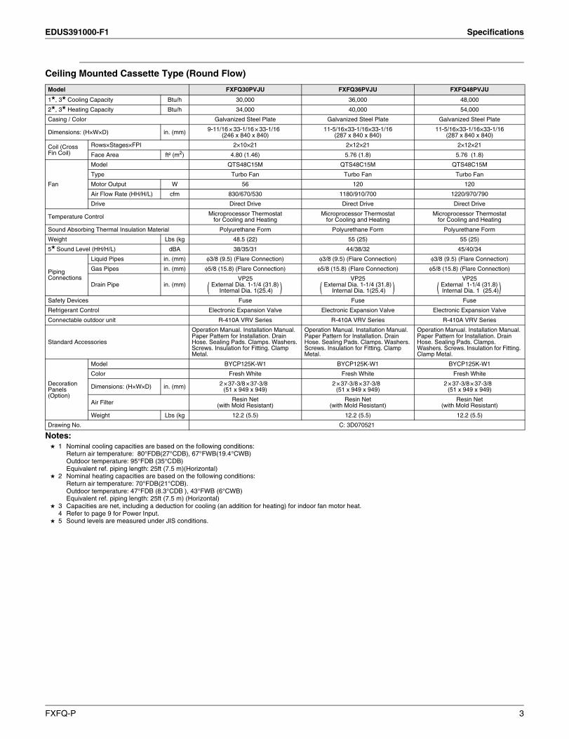
Ceiling Mounted Cassette Type (Round Flow)
Notes: 1 Nominal cooling capacities are based on the following conditions:
Return air temperature: 80°FDB(27°CDB), 67°FWB(19.4°CWB) Outdoor temperature: 95°FDB (35°CDB)Equivalent ref. piping length: 25ft (7.5 m)(Horizontal)
2 Nominal heating capacities are based on the following conditions: Return air temperature: 70°FDB(21°CDB). Outdoor temperature: 47°FDB (8.3°CDB ), 43°FWB (6°CWB)Equivalent ref. piping length: 25ft (7.5 m) (Horizontal)
3 Capacities are net, including a deduction for cooling (an addition for heating) for indoor fan motor heat.4 Refer to page 9 for Power Input.
5 Sound levels are measured under JIS conditions.
Model FXFQ30PVJU FXFQ36PVJU FXFQ48PVJU
1, 3 Cooling Capacity Btu/h 30,000 36,000 48,000
2, 3 Heating Capacity Btu/h 34,000 40,000 54,000
Casing / Color Galvanized Steel Plate Galvanized Steel Plate Galvanized Steel Plate
Dimensions: (H×W×D) in. (mm) 9-11/16 × 33-1/16 × 33-1/16 (246 x 840 x 840)
11-5/16×33-1/16×33-1/16 (287 x 840 x 840)
11-5/16×33-1/16×33-1/16 (287 x 840 x 840)
Coil (Cross Fin Coil)
Rows×Stages×FPI 2×10×21 2×12×21 2×12×21
Face Area ft² (m2) 4.80 (1.46) 5.76 (1.8) 5.76 (1.8)
Fan
Model QTS48C15M QTS48C15M QTS48C15M
Type Turbo Fan Turbo Fan Turbo Fan
Motor Output W 56 120 120
Air Flow Rate (HH/H/L) cfm 830/670/530 1180/910/700 1220/970/790
Drive Direct Drive Direct Drive Direct Drive
Temperature Control Microprocessor Thermostatfor Cooling and Heating
Microprocessor Thermostatfor Cooling and Heating
Microprocessor Thermostatfor Cooling and Heating
Sound Absorbing Thermal Insulation Material Polyurethane Form Polyurethane Form Polyurethane Form
Weight Lbs (kg 48.5 (22) 55 (25) 55 (25)
5 Sound Level (HH/H/L) dBA 38/35/31 44/38/32 45/40/34
Piping Connections
Liquid Pipes in. (mm) φ3/8 (9.5) (Flare Connection) φ3/8 (9.5) (Flare Connection) φ3/8 (9.5) (Flare Connection)
Gas Pipes in. (mm) φ5/8 (15.8) (Flare Connection) φ5/8 (15.8) (Flare Connection) φ5/8 (15.8) (Flare Connection)
Drain Pipe in. (mm)VP25
External Dia. 1-1/4 (31.8) Internal Dia. 1(25.4)
VP25External Dia. 1-1/4 (31.8)
Internal Dia. 1(25.4)
VP25External 1-1/4 (31.8) Internal Dia. 1 (25.4)
Safety Devices Fuse Fuse Fuse
Refrigerant Control Electronic Expansion Valve Electronic Expansion Valve Electronic Expansion Valve
Connectable outdoor unit R-410A VRV Series R-410A VRV Series R-410A VRV Series
Standard Accessories
Operation Manual. Installation Manual. Paper Pattern for Installation. Drain Hose. Sealing Pads. Clamps. Washers. Screws. Insulation for Fitting. Clamp Metal.
Operation Manual. Installation Manual. Paper Pattern for Installation. Drain Hose. Sealing Pads. Clamps. Washers. Screws. Insulation for Fitting. Clamp Metal.
Operation Manual. Installation Manual. Paper Pattern for Installation. Drain Hose. Sealing Pads. Clamps. Washers. Screws. Insulation for Fitting. Clamp Metal.
Decoration Panels(Option)
Model BYCP125K-W1 BYCP125K-W1 BYCP125K-W1
Color Fresh White Fresh White Fresh White
Dimensions: (H×W×D) in. (mm) 2 × 37-3/8 × 37-3/8 (51 x 949 x 949)
2 × 37-3/8 × 37-3/8 (51 x 949 x 949)
2 × 37-3/8 × 37-3/8 (51 x 949 x 949)
Air Filter Resin Net(with Mold Resistant)
Resin Net(with Mold Resistant)
Resin Net(with Mold Resistant)
Weight Lbs (kg 12.2 (5.5) 12.2 (5.5) 12.2 (5.5)
Drawing No. C: 3D070521
( ) ( ) ( )
FXFQ-P 3

Dimensions EDUS391000-F1
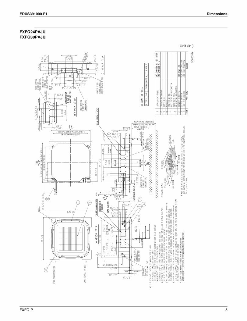
2. Dimensions
FXFQ09PVJUFXFQ12PVJUFXFQ18PVJU
Unit (in.)
3D07
0522
DO N
OT PL
ACE T
HE U
NIT I
N AR
EAS W
ITH E
XCES
SIVE
HUM
IDITY
.W
HEN
HUMI
DITY
EXCE
EDS 8
0%, C
ONDE
NSAT
ION
CAN
FORM
ON
THE U
NIT.
4 FXFQ-P
EDUS391000-F1 Dimensions
FXFQ24PVJUFXFQ30PVJU
Unit (in.)
3D07
0524
DO N
OT PL
ACE T
HE U
NIT I
N AR
EAS W
ITH E
XCES
SIVE
HUM
IDITY
.W
HEN
HUMI
DITY
EXCE
EDS 8
0%, C
ONDE
NSAT
ION
CAN
FORM
ON
THE U
NIT.
FXFQ-P 5
Dimensions EDUS391000-F1
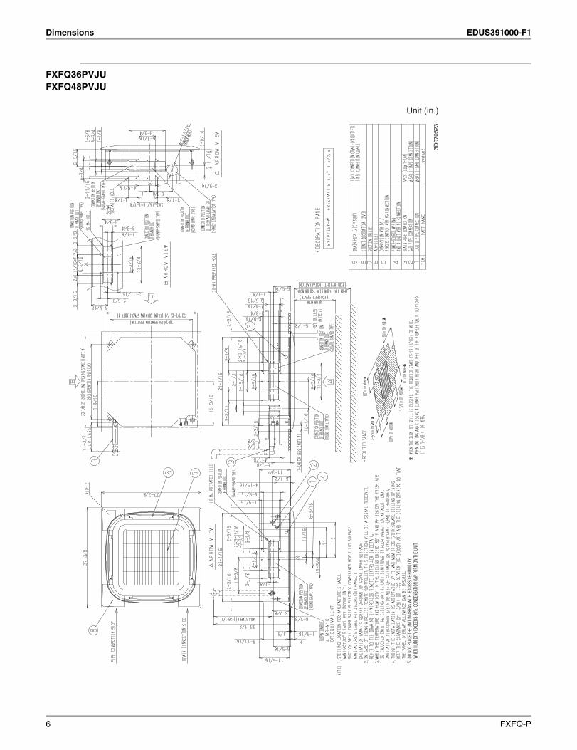
FXFQ36PVJUFXFQ48PVJU
Unit (in.)
3D07
0523
DO N
OT PL
ACE T
HE U
NIT I
N AR
EAS W
ITH E
XCES
SIVE
HUM
IDITY
.W
HEN
HUMI
DITY
EXCE
EDS 8
0%, C
ONDE
NSAT
ION
CAN
FORM
ON
THE U
NIT.
6 FXFQ-P
EDUS391000-F1 Piping Diagrams
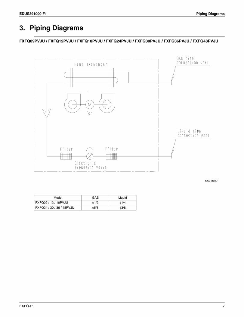
3. Piping Diagrams
FXFQ09PVJU / FXFQ12PVJU / FXFQ18PVJU / FXFQ24PVJU / FXFQ30PVJU / FXFQ36PVJU / FXFQ48PVJU
Model GAS Liquid
FXFQ09 / 12 / 18PVJU φ1/2 φ1/4
FXFQ24 / 30 / 36 / 48PVJU φ5/8 φ3/8
4D024460D
FXFQ-P 7
Wiring Diagrams EDUS391000-F1
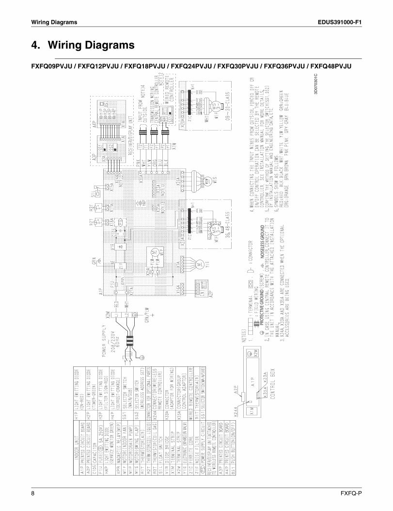
4. Wiring Diagrams
FXFQ09PVJU / FXFQ12PVJU / FXFQ18PVJU / FXFQ24PVJU / FXFQ30PVJU / FXFQ36PVJU / FXFQ48PVJU
3D07
0301
C
PROT
ECTIV
E GRO
UND
NOISE
LESS
GRO
UND
8 FXFQ-P
EDUS391000-F1 Electric Characteristics
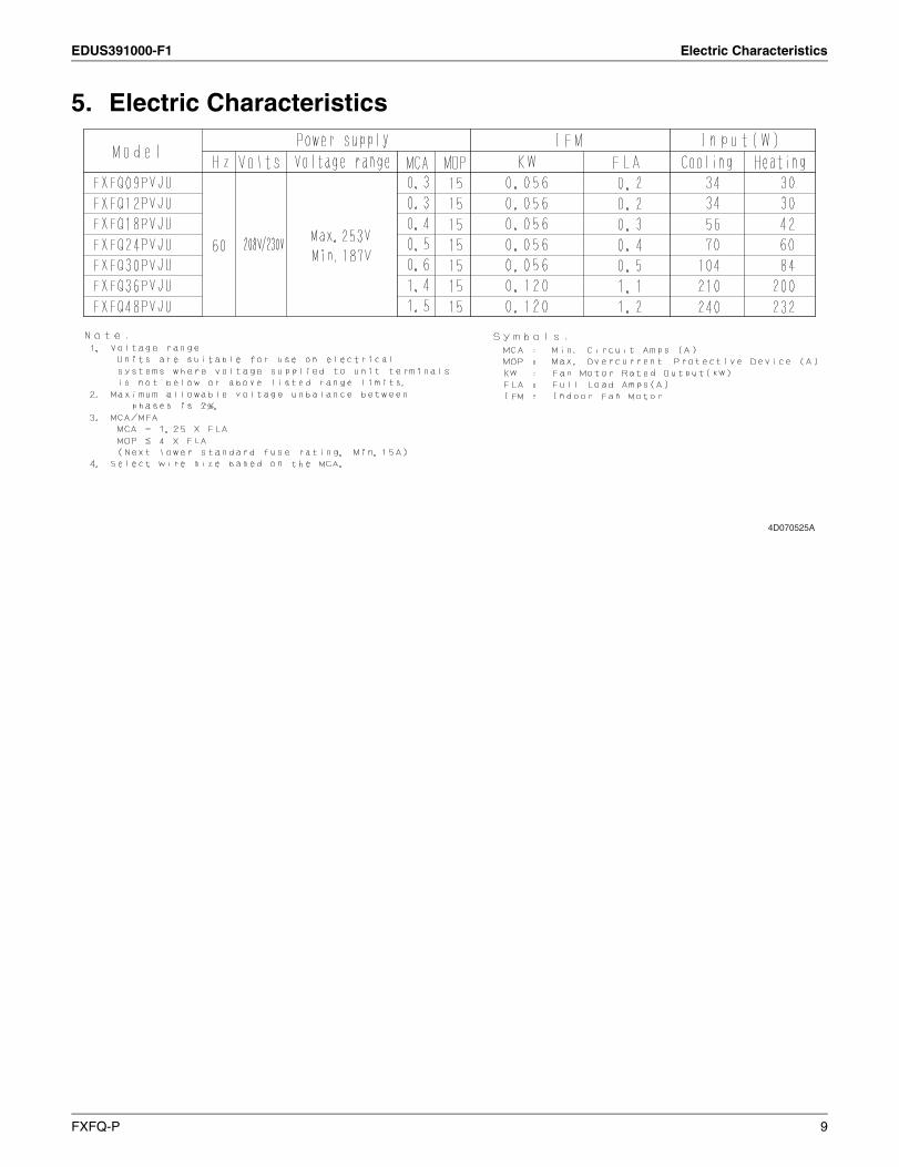
5. Electric Characteristics
4D070525A
FXFQ-P 9
Capacity Tables EDUS391000-F1
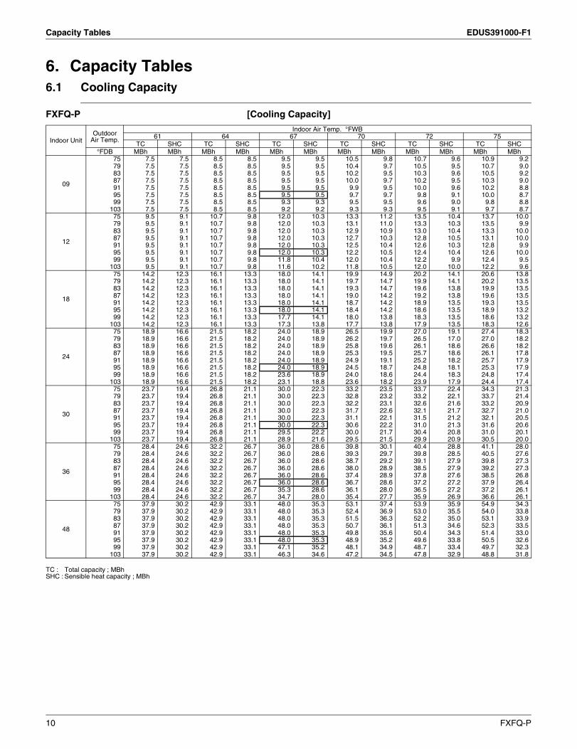
6. Capacity Tables6.1 Cooling Capacity
FXFQ-P [Cooling Capacity]
TC : Total capacity ; MBhSHC : Sensible heat capacity ; MBh
Indoor UnitOutdoor
Air Temp.
Indoor Air Temp. °FWB61 64 67 70 72 75
TC SHC TC SHC TC SHC TC SHC TC SHC TC SHC°FDB MBh MBh MBh MBh MBh MBh MBh MBh MBh MBh MBh MBh
09
75 7.5 7.5 8.5 8.5 9.5 9.5 10.5 9.8 10.7 9.6 10.9 9.279 7.5 7.5 8.5 8.5 9.5 9.5 10.4 9.7 10.5 9.5 10.7 9.083 7.5 7.5 8.5 8.5 9.5 9.5 10.2 9.5 10.3 9.6 10.5 9.287 7.5 7.5 8.5 8.5 9.5 9.5 10.0 9.7 10.2 9.5 10.3 9.091 7.5 7.5 8.5 8.5 9.5 9.5 9.9 9.5 10.0 9.6 10.2 8.895 7.5 7.5 8.5 8.5 9.5 9.5 9.7 9.7 9.8 9.1 10.0 8.799 7.5 7.5 8.5 8.5 9.3 9.3 9.5 9.5 9.6 9.0 9.8 8.8
103 7.5 7.5 8.5 8.5 9.2 9.2 9.3 9.3 9.5 9.1 9.7 8.7
12
75 9.5 9.1 10.7 9.8 12.0 10.3 13.3 11.2 13.5 10.4 13.7 10.079 9.5 9.1 10.7 9.8 12.0 10.3 13.1 11.0 13.3 10.3 13.5 9.983 9.5 9.1 10.7 9.8 12.0 10.3 12.9 10.9 13.0 10.4 13.3 10.087 9.5 9.1 10.7 9.8 12.0 10.3 12.7 10.3 12.8 10.5 13.1 10.091 9.5 9.1 10.7 9.8 12.0 10.3 12.5 10.4 12.6 10.3 12.8 9.995 9.5 9.1 10.7 9.8 12.0 10.3 12.2 10.5 12.4 10.4 12.6 10.099 9.5 9.1 10.7 9.8 11.8 10.4 12.0 10.4 12.2 9.9 12.4 9.5
103 9.5 9.1 10.7 9.8 11.6 10.2 11.8 10.5 12.0 10.0 12.2 9.6
18
75 14.2 12.3 16.1 13.3 18.0 14.1 19.9 14.9 20.2 14.1 20.6 13.879 14.2 12.3 16.1 13.3 18.0 14.1 19.7 14.7 19.9 14.1 20.2 13.583 14.2 12.3 16.1 13.3 18.0 14.1 19.3 14.7 19.6 13.8 19.9 13.587 14.2 12.3 16.1 13.3 18.0 14.1 19.0 14.2 19.2 13.8 19.6 13.591 14.2 12.3 16.1 13.3 18.0 14.1 18.7 14.2 18.9 13.5 19.3 13.595 14.2 12.3 16.1 13.3 18.0 14.1 18.4 14.2 18.6 13.5 18.9 13.299 14.2 12.3 16.1 13.3 17.7 14.1 18.0 13.8 18.3 13.5 18.6 13.2
103 14.2 12.3 16.1 13.3 17.3 13.8 17.7 13.8 17.9 13.5 18.3 12.6
24
75 18.9 16.6 21.5 18.2 24.0 18.9 26.5 19.9 27.0 19.1 27.4 18.379 18.9 16.6 21.5 18.2 24.0 18.9 26.2 19.7 26.5 17.0 27.0 18.283 18.9 16.6 21.5 18.2 24.0 18.9 25.8 19.6 26.1 18.6 26.6 18.287 18.9 16.6 21.5 18.2 24.0 18.9 25.3 19.5 25.7 18.6 26.1 17.891 18.9 16.6 21.5 18.2 24.0 18.9 24.9 19.1 25.2 18.2 25.7 17.995 18.9 16.6 21.5 18.2 24.0 18.9 24.5 18.7 24.8 18.1 25.3 17.999 18.9 16.6 21.5 18.2 23.6 18.9 24.0 18.6 24.4 18.3 24.8 17.4
103 18.9 16.6 21.5 18.2 23.1 18.8 23.6 18.2 23.9 17.9 24.4 17.4
30
75 23.7 19.4 26.8 21.1 30.0 22.3 33.2 23.5 33.7 22.4 34.3 21.379 23.7 19.4 26.8 21.1 30.0 22.3 32.8 23.2 33.2 22.1 33.7 21.483 23.7 19.4 26.8 21.1 30.0 22.3 32.2 23.1 32.6 21.6 33.2 20.987 23.7 19.4 26.8 21.1 30.0 22.3 31.7 22.6 32.1 21.7 32.7 21.091 23.7 19.4 26.8 21.1 30.0 22.3 31.1 22.1 31.5 21.2 32.1 20.595 23.7 19.4 26.8 21.1 30.0 22.3 30.6 22.2 31.0 21.3 31.6 20.699 23.7 19.4 26.8 21.1 29.5 22.2 30.0 21.7 30.4 20.8 31.0 20.1
103 23.7 19.4 26.8 21.1 28.9 21.6 29.5 21.5 29.9 20.9 30.5 20.0
36
75 28.4 24.6 32.2 26.7 36.0 28.6 39.8 30.1 40.4 28.8 41.1 28.079 28.4 24.6 32.2 26.7 36.0 28.6 39.3 29.7 39.8 28.5 40.5 27.683 28.4 24.6 32.2 26.7 36.0 28.6 38.7 29.2 39.1 27.9 39.8 27.387 28.4 24.6 32.2 26.7 36.0 28.6 38.0 28.9 38.5 27.9 39.2 27.391 28.4 24.6 32.2 26.7 36.0 28.6 37.4 28.9 37.8 27.6 38.5 26.895 28.4 24.6 32.2 26.7 36.0 28.6 36.7 28.6 37.2 27.2 37.9 26.499 28.4 24.6 32.2 26.7 35.3 28.6 36.1 28.0 36.5 27.2 37.2 26.1
103 28.4 24.6 32.2 26.7 34.7 28.0 35.4 27.7 35.9 26.9 36.6 26.1
48
75 37.9 30.2 42.9 33.1 48.0 35.3 53.1 37.4 53.9 35.9 54.9 34.379 37.9 30.2 42.9 33.1 48.0 35.3 52.4 36.9 53.0 35.5 54.0 33.883 37.9 30.2 42.9 33.1 48.0 35.3 51.5 36.3 52.2 35.0 53.1 33.987 37.9 30.2 42.9 33.1 48.0 35.3 50.7 36.1 51.3 34.6 52.3 33.591 37.9 30.2 42.9 33.1 48.0 35.3 49.8 35.6 50.4 34.3 51.4 33.095 37.9 30.2 42.9 33.1 48.0 35.3 48.9 35.2 49.6 33.8 50.5 32.699 37.9 30.2 42.9 33.1 47.1 35.2 48.1 34.9 48.7 33.4 49.7 32.3
103 37.9 30.2 42.9 33.1 46.3 34.6 47.2 34.5 47.8 32.9 48.8 31.8
10 FXFQ-P
EDUS391000-F1 Capacity Tables
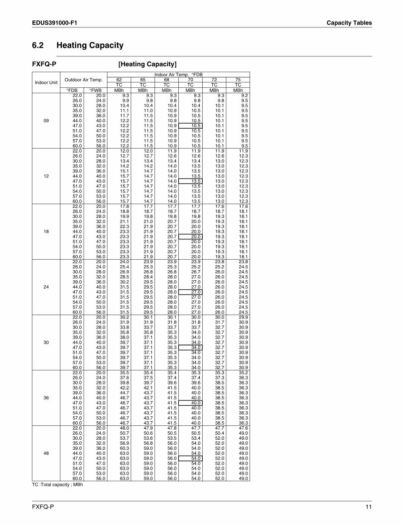
6.2 Heating Capacity
FXFQ-P [Heating Capacity]
TC :Total capacity ; MBh
Indoor UnitOutdoor Air Temp.
Indoor Air Temp. °FDB62 65 68 70 72 75TC TC TC TC TC TC
°FDB °FWB MBh MBh MBh MBh MBh MBh
09
22.0 20.0 9.3 9.3 9.3 9.3 9.3 9.226.0 24.0 9.9 9.8 9.8 9.8 9.8 9.530.0 28.0 10.4 10.4 10.4 10.4 10.1 9.535.0 32.0 11.1 11.0 10.9 10.5 10.1 9.539.0 36.0 11.7 11.5 10.9 10.5 10.1 9.544.0 40.0 12.2 11.5 10.9 10.5 10.1 9.547.0 43.0 12.2 11.5 10.9 10.5 10.1 9.551.0 47.0 12.2 11.5 10.9 10.5 10.1 9.554.0 50.0 12.2 11.5 10.9 10.5 10.1 9.557.0 53.0 12.2 11.5 10.9 10.5 10.1 9.560.0 56.0 12.2 11.5 10.9 10.5 10.1 9.5
12
22.0 20.0 12.0 12.0 11.9 11.9 11.9 11.926.0 24.0 12.7 12.7 12.6 12.6 12.6 12.330.0 28.0 13.4 13.4 13.4 13.4 13.0 12.335.0 32.0 14.2 14.2 14.0 13.5 13.0 12.339.0 36.0 15.1 14.7 14.0 13.5 13.0 12.344.0 40.0 15.7 14.7 14.0 13.5 13.0 12.347.0 43.0 15.7 14.7 14.0 13.5 13.0 12.351.0 47.0 15.7 14.7 14.0 13.5 13.0 12.354.0 50.0 15.7 14.7 14.0 13.5 13.0 12.357.0 53.0 15.7 14.7 14.0 13.5 13.0 12.360.0 56.0 15.7 14.7 14.0 13.5 13.0 12.3
18
22.0 20.0 17.8 17.7 17.7 17.7 17.6 17.626.0 24.0 18.8 18.7 18.7 18.7 18.7 18.130.0 28.0 19.9 19.8 19.8 19.8 19.3 18.135.0 32.0 21.1 21.0 20.7 20.0 19.3 18.139.0 36.0 22.3 21.9 20.7 20.0 19.3 18.144.0 40.0 23.3 21.9 20.7 20.0 19.3 18.147.0 43.0 23.3 21.9 20.7 20.0 19.3 18.151.0 47.0 23.3 21.9 20.7 20.0 19.3 18.154.0 50.0 23.3 21.9 20.7 20.0 19.3 18.157.0 53.0 23.3 21.9 20.7 20.0 19.3 18.160.0 56.0 23.3 21.9 20.7 20.0 19.3 18.1
24
22.0 20.0 24.0 23.9 23.9 23.9 23.8 23.826.0 24.0 25.4 25.3 25.3 25.2 25.2 24.530.0 28.0 26.9 26.8 26.8 26.7 26.0 24.535.0 32.0 28.5 28.4 28.0 27.0 26.0 24.539.0 36.0 30.2 29.5 28.0 27.0 26.0 24.544.0 40.0 31.5 29.5 28.0 27.0 26.0 24.547.0 43.0 31.5 29.5 28.0 27.0 26.0 24.551.0 47.0 31.5 29.5 28.0 27.0 26.0 24.554.0 50.0 31.5 29.5 28.0 27.0 26.0 24.557.0 53.0 31.5 29.5 28.0 27.0 26.0 24.560.0 56.0 31.5 29.5 28.0 27.0 26.0 24.5
30
22.0 20.0 30.2 30.1 30.1 30.0 30.0 29.926.0 24.0 31.9 31.9 31.8 31.8 31.7 30.930.0 28.0 33.8 33.7 33.7 33.7 32.7 30.935.0 32.0 35.8 35.8 35.3 34.0 32.7 30.939.0 36.0 38.0 37.1 35.3 34.0 32.7 30.944.0 40.0 39.7 37.1 35.3 34.0 32.7 30.947.0 43.0 39.7 37.1 35.3 34.0 32.7 30.951.0 47.0 39.7 37.1 35.3 34.0 32.7 30.954.0 50.0 39.7 37.1 35.3 34.0 32.7 30.957.0 53.0 39.7 37.1 35.3 34.0 32.7 30.960.0 56.0 39.7 37.1 35.3 34.0 32.7 30.9
36
22.0 20.0 35.5 35.4 35.4 35.3 35.3 35.226.0 24.0 37.6 37.5 37.4 37.4 37.3 36.330.0 28.0 39.8 39.7 39.6 39.6 38.5 36.335.0 32.0 42.2 42.1 41.5 40.0 38.5 36.339.0 36.0 44.7 43.7 41.5 40.0 38.5 36.344.0 40.0 46.7 43.7 41.5 40.0 38.5 36.347.0 43.0 46.7 43.7 41.5 40.0 38.5 36.351.0 47.0 46.7 43.7 41.5 40.0 38.5 36.354.0 50.0 46.7 43.7 41.5 40.0 38.5 36.357.0 53.0 46.7 43.7 41.5 40.0 38.5 36.360.0 56.0 46.7 43.7 41.5 40.0 38.5 36.3
48
22.0 20.0 48.0 47.9 47.8 47.7 47.7 47.626.0 24.0 50.7 50.6 50.5 50.5 50.4 49.030.0 28.0 53.7 53.6 53.5 53.4 52.0 49.035.0 32.0 56.9 56.8 56.0 54.0 52.0 49.039.0 36.0 60.3 59.0 56.0 54.0 52.0 49.044.0 40.0 63.0 59.0 56.0 54.0 52.0 49.047.0 43.0 63.0 59.0 56.0 54.0 52.0 49.051.0 47.0 63.0 59.0 56.0 54.0 52.0 49.054.0 50.0 63.0 59.0 56.0 54.0 52.0 49.057.0 53.0 63.0 59.0 56.0 54.0 52.0 49.060.0 56.0 63.0 59.0 56.0 54.0 52.0 49.0
FXFQ-P 11
Sound Levels (Reference) EDUS391000-F1
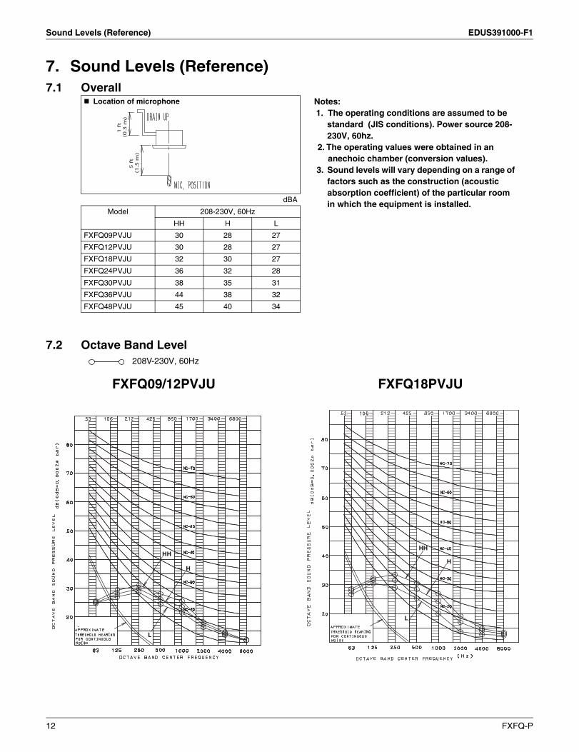
7. Sound Levels (Reference)7.1 Overall
7.2 Octave Band Level208V-230V, 60Hz
Location of microphone Notes:1. The operating conditions are assumed to be
standard (JIS conditions). Power source 208-230V, 60hz.
2. The operating values were obtained in an anechoic chamber (conversion values).
3. Sound levels will vary depending on a range of factors such as the construction (acoustic absorption coefficient) of the particular room in which the equipment is installed.dBA
Model 208-230V, 60Hz
HH H L
FXFQ09PVJU 30 28 27
FXFQ12PVJU 30 28 27
FXFQ18PVJU 32 30 27
FXFQ24PVJU 36 32 28
FXFQ30PVJU 38 35 31
FXFQ36PVJU 44 38 32
FXFQ48PVJU 45 40 34
5
ft
(1
.5 m
)
1
ft
(0
.3 m
)
HH
H
L
HH
H
L
FXFQ09/12PVJU FXFQ18PVJU
12 FXFQ-P
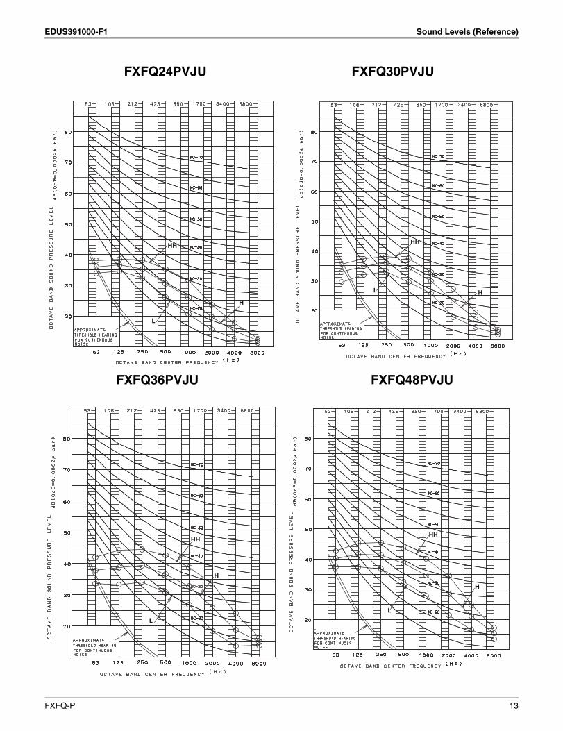
EDUS391000-F1 Sound Levels (Reference)
FXFQ36PVJU FXFQ48PVJU
HH
H
L
HH
H L
HH
H
L L
H
HH
FXFQ24PVJU FXFQ30PVJU
FXFQ-P 13
Center of Gravity EDUS391000-F1
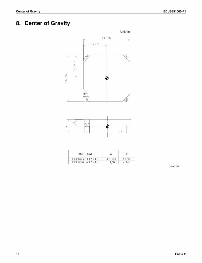
8. Center of Gravity
4D070529
Unit (in.)
14 FXFQ-P

EDUS391000-F1 Installation
9. Installation
3P161684-5H
English 1
VRV SYSTEM Inverter Heat Pump Installation manual
CONTENTS1. SAFETY CONSIDERATIONS........................................................................................ 1
2. BEFORE INSTALLATION.............................................................................................. 3
3. SELECTING INSTALLATION SITE ............................................................................... 6
4. PREPARATIONS BEFORE INSTALLATION ................................................................ 7
5. INDOOR UNIT INSTALLATION..................................................................................... 9
6. REFRIGERANT PIPING WORK.................................................................................. 10
7. DRAIN PIPING WORK ................................................................................................ 13
8. ELECTRIC WIRING WORK......................................................................................... 16
9. WIRING EXAMPLE AND HOW TO SET THE REMOTE CONTROLLER ................... 17
10. INSTALLATION OF THE DECORATION PANEL...........................................................24
11. FIELD SETTING .......................................................................................................... 24
12. TEST OPERATION...................................................................................................... 26
1. SAFETY CONSIDERATIONSRead these “SAFETY CONSIDERATIONS for Installation” carefully before installing air conditioning equip-ment. After completing the installation, make sure that the unit operates properly during the startup operation.Instruct the customer on how to operate and maintain the unit. Inform customers that they should store this Installation Manual with the Operation Manual for future reference.Always use a licensed installer or contractor to install this product. Improper installation can result in water or refrigerant leakage, electrical shock, fire, or explosion.Meanings of DANGER, WARNING, CAUTION, and NOTE Symbols:
DANGER ........... Indicates an imminently hazardous situation which, if not avoided, will result in death or serious injury.
WARNING ......... Indicates a potentially hazardous situation which, if not avoided, could result in death or serious injury.
CAUTION .......... Indicates a potentially hazardous situation which, if not avoided, may result in minor or moderate injury. It may also be used to alert against unsafe practices.
NOTE................. Indicates situations that may result in equipment or property-damage accidents only.
DANGER• Refrigerant gas is heavier than air and replaces oxygen. A massive leak can lead to oxygen depletion,
especially in basements, and an asphyxiation hazard could occur leading to serious injury or death.• Do not ground units to water pipes, gas pipes, telephone wires, or lightning rods as incomplete grounding
can cause a severe shock hazard resulting in severe injury or death. Additionally, grounding to gas pipes could cause a gas leak and potential explosion causing severe injury or death.
• If refrigerant gas leaks during installation, ventilate the area immediately. Refrigerant gas may produce toxic gas if it comes in contact with fire. Exposure to this gas could cause severe injury or death.
• After completing the installation work, check that the refrigerant gas does not leak throughout the system.• Do not install unit in an area where flammable materials are present due to risk of explosions that can cause
serious injury or death.
FXFQ-P 15
Installation EDUS391000-F1
3P161684-5H
2 English
• Safely dispose all packing and transportation materials in accordance with federal/state/local laws or ordi-nances. Packing materials such as nails and other metal or wood parts, including plastic packing mate-rials used for transportation may cause injuries or death by suffocation.
WARNING• Only qualified personnel must carry out the installation work. Installation must be done in accordance with
this installation manual. Improper installation may result in water leakage, electric shock, or fire.• When installing the unit in a small room, take measures to keep the refrigerant concentration from exceed-
ing allowable safety limits. Excessive refrigerant leaks, in the event of an accident in a closed ambient space, can lead to oxygen deficiency.
• Use only specified accessories and parts for installation work. Failure to use specified parts may result in water leakage, electric shocks, fire, or the unit falling.
• Install the air conditioner on a foundation strong enough that it can withstand the weight of the unit. A foun-dation of insufficient strength may result in the unit falling and causing injuries.
• Take into account strong winds, typhoons, or earthquakes when installing. Improper installation may result in the unit falling and causing accidents.
• Make sure that a separate power supply circuit is provided for this unit and that all electrical work is carried out by qualified personnel according to local, state, and national regulations. An insufficient power supply capacity or improper electrical construction may lead to electric shocks or fire.
• Make sure that all wiring is secured, that specified wires are used, and that no external forces act on the ter-minal connections or wires. Improper connections or installation may result in fire.
• When wiring, position the wires so that the control box lid can be securely fastened. Improper positioning of the control box lid may result in electric shocks, fire, or the terminals overheating.
• Before touching electrical parts, turn off the unit.• Be sure to install a ground fault circuit interrupter if one is not already available. This helps prevent electrical
shocks or fire.• Securely fasten the outside unit terminal cover (panel). If the terminal cover/panel is not installed properly,
dust or water may enter the outside unit causing fire or electric shock.• When installing or relocating the system, keep the refrigerant circuit free from substances other than the
specified refrigerant (R410A) such as air. Any presence of air or other foreign substance in the refrigerant circuit can cause an abnormal pressure rise or rupture, resulting in injury.
• Do not change the setting of the protection devices. If the pressure switch, thermal switch, or other pro-tection device is shorted and operated forcibly, or parts other than those specified by Daikin are used, fire or explosion may occur.
CAUTION• Do not touch the switch with wet fingers. Touching a switch with wet fingers can cause electric shock.• Do not allow children to play on or around the unit to prevent injury.• Do not touch the refrigerant pipes during and immediately after operation as the refrigerant pipes may be
hot or cold, depending on the condition of the refrigerant flowing through the refrigerant piping, compressor, and other refrigerant cycle parts. Your hands may suffer burns or frostbite if you touch the refrigerant pipes. To avoid injury, give the pipes time to return to normal temperature or, if you must touch them, be sure to wear proper gloves.
• Heat exchanger fins are sharp enough to cut.To avoid injury wear glove or cover the fins when working around them.
• Install drain piping to proper drainage. Improper drain piping may result in water leakage and property dam-age.
• Insulate piping to prevent condensation.• Be careful when transporting the product.• Do not turn off the power immediately after stopping operation. Always wait for at least 5 minutes before
turning off the power. Otherwise, water leakage may occur.• Do not use a charging cylinder. Using a charging cylinder may cause the refrigerant to deteriorate.
16 FXFQ-P
EDUS391000-F1 Installation
3P161684-5H
English 3
• Refrigerant R410A in the system must be kept clean, dry, and tight.(a) Clean and Dry -- Foreign materials (including mineral oils such as SUNISO oil or moisture) should be
prevented from getting into the system.(b) Tight -- R410A does not contain any chlorine, does not destroy the ozone layer, and does not reduce
the earth’s protection again harmful ultraviolet radiation. R410A can contribute to the greenhouse effect if it is released. Therefore take proper measures to check for the tightness of the refrigerant piping installation. Read the chapter Refrigerant Piping and follow the procedures.
• Since R410A is a blend, the required additional refrigerant must be charged in its liquid state. If the refrig-erant is charged in a state of gas, its composition can change and the system will not work properly.
• The indoor unit is for R410A. See the catalog for indoor models that can be connected. Normal operation is not possible when connected to other units.
• Indoor units are for indoor installation only. Outdoor units can be installed either outdoors or indoors.• Do not install the air conditioner in the following locations:
(a) Where a mineral oil mist or oil spray or vapor is produced, for example, in a kitchen.Plastic parts may deteriorate and fall off or result in water leakage.
(b) Where corrosive gas, such as sulfurous acid gas, is produced.Corroding copper pipes or soldered parts may result in refrigerant leakage.
(c) Near machinery emitting electromagnetic waves.Electromagnetic waves may disturb the operation of the control system and cause the unit to malfunction.
(d) Where flammable gas may leak, where there is carbon fiber, or ignitable dust suspension in the air, or where volatile flammables such as thinner or gasoline are handled. Operating the unit in such condi-tions can cause a fire.
• Take adequate measures to prevent the outside unit from being used as a shelter by small animals. Small animals making contact with electrical parts can cause malfunctions, smoke, or fire. Instruct the customer to keep the area around the unit clean.
NOTE• Install the power supply and control wires for the indoor and outdoor units at least 3.5 feet away from tele-
visions or radios to prevent image interference or noise. Depending on the radio waves, a distance of 3.5 feet may not be sufficient to eliminate the noise.
• Dismantling the unit, treatment of the refrigerant, oil and additional parts must be done in accordance with the relevant local, state, and national regulations.
• Do not use the following tools that are used with conventional refrigerants: gauge manifold, charge hose, gas leak detector, reverse flow check valve, refrigerant charge base, vacuum gauge, or refrigerant recovery equipment.
• If the conventional refrigerant and refrigerator oil are mixed in R410A, the refrigerant may deteriorate.• This air conditioner is an appliance that should not be accessible to the general public.• The wall thickness of field-installed pipes should be selected in accordance with the relevant local, state,
and national regulations.
2. BEFORE INSTALLATIONDo not exert pressure on the resin parts when opening the unit or when moving it after opening.Be sure to check the type of R410A refrigerant to be used before doing any work. (Using an incorrect refrigerant will prevent normal operation of the unit.)• When opening the unit or moving it after opening, be sure to lift it by holding on to the lifting lugs without
exerting any pressure on other parts, especially, drain piping, and other resin parts.• Decide upon a line of transport.• Leave the unit inside its packaging while moving, until reaching the installation site. Use a sling of soft mate-
rial, where unpacking is unavoidable or protective plates together with a rope when lifting, to avoid damage or scratches to the unit.
• Refer to the installation manual of the outdoor unit for items not described in this manual.• Do not dispose of any parts necessary for installation until the installation is complete.
FXFQ-P 17
Installation EDUS391000-F1
3P161684-5H
4 English
1. PRECAUTIONS• Be sure to read this manual before installing the indoor unit.• When selecting installation site, refer to the paper pattern.• This unit is suitable for installation in a household, commercial and light industrial environment.• Do not install or operate the unit in rooms mentioned below.
• Laden with mineral oil, or filled with oil vapor or spray like in kitchens. (Plastic parts may deteriorate.)• Where corrosive gas like sulfurous gas exists. (Copper tubing and brazed spots may corrode.)• Where volatile flammable gas like thinner or gasoline is used.• Where machines can generate electromagnetic waves. (Control system may malfunction.)• Where the air contains high levels of salt such as that near the ocean and where voltage fluctuates
greatly such as that in factories. Also in vehicles or vessels.
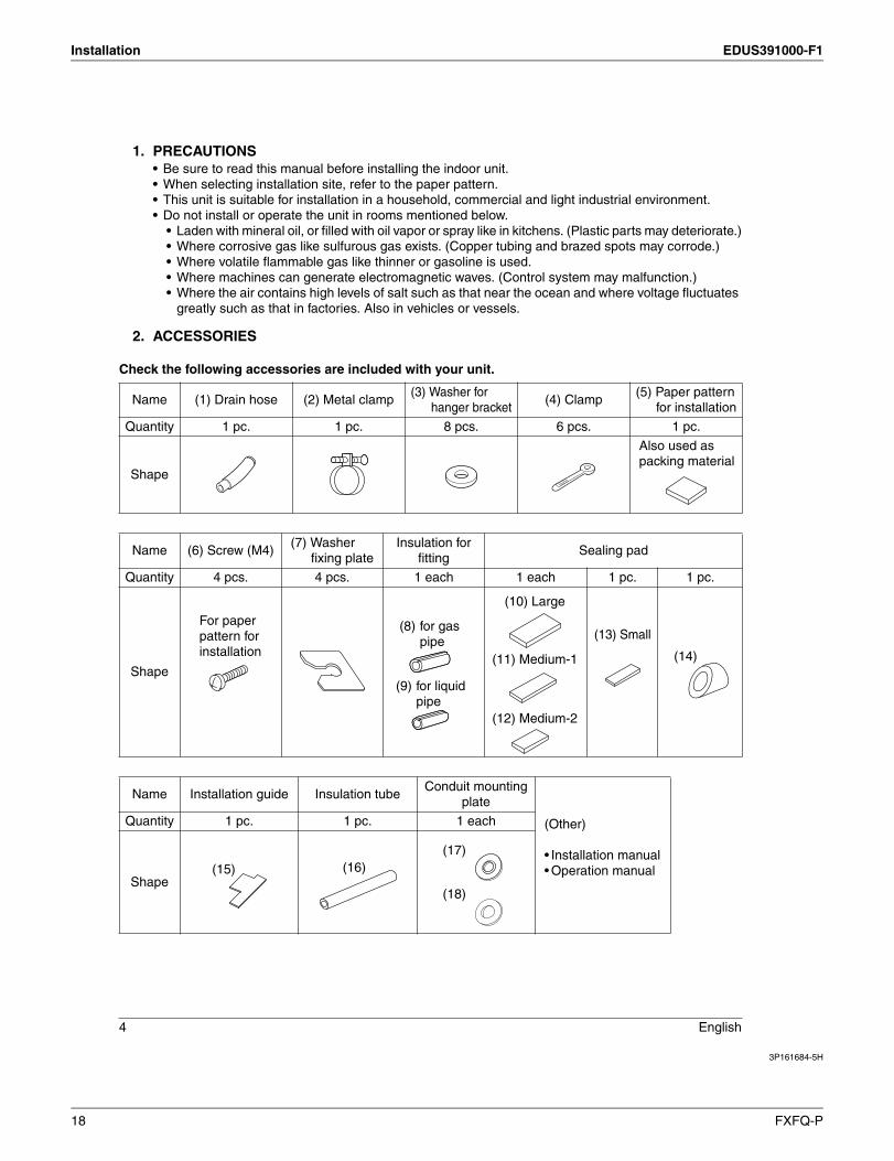
2. ACCESSORIES
Check the following accessories are included with your unit.
Name (1) Drain hose (2) Metal clamp(3) Washer for
hanger bracket(4) Clamp
(5) Paper pattern for installation
Quantity 1 pc. 1 pc. 8 pcs. 6 pcs. 1 pc.
Shape
Also used as packing material
Name (6) Screw (M4)(7) Washer
fixing plateInsulation for
fittingSealing pad
Quantity 4 pcs. 4 pcs. 1 each 1 each 1 pc. 1 pc.
Shape
(13) Small
Name Installation guide Insulation tubeConduit mounting
plate
(Other)
• Installation manual• Operation manual
Quantity 1 pc. 1 pc. 1 each
Shape
For paper pattern for installation
(8) for gas pipe
(9) for liquid pipe
(11) Medium-1
(12) Medium-2
(10) Large
(14)
(15) (16)(17)
(18)
18 FXFQ-P
EDUS391000-F1 Installation
3P161684-5H
English 5
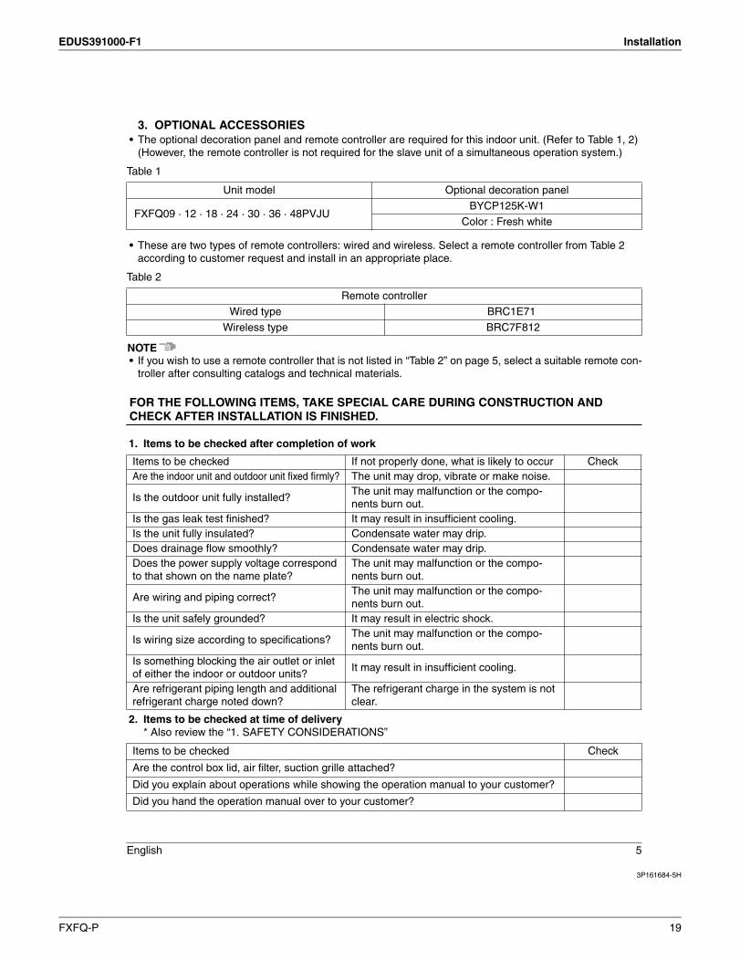
3. OPTIONAL ACCESSORIES• The optional decoration panel and remote controller are required for this indoor unit. (Refer to Table 1, 2)
(However, the remote controller is not required for the slave unit of a simultaneous operation system.)
Table 1
• These are two types of remote controllers: wired and wireless. Select a remote controller from Table 2 according to customer request and install in an appropriate place.
Table 2
NOTE• If you wish to use a remote controller that is not listed in “Table 2” on page 5, select a suitable remote con-
troller after consulting catalogs and technical materials.
FOR THE FOLLOWING ITEMS, TAKE SPECIAL CARE DURING CONSTRUCTION AND CHECK AFTER INSTALLATION IS FINISHED.
1. Items to be checked after completion of work
2. Items to be checked at time of delivery* Also review the “1. SAFETY CONSIDERATIONS”
Unit model Optional decoration panel
FXFQ09 · 12 · 18 · 24 · 30 · 36 · 48PVJUBYCP125K-W1
Color : Fresh white
Remote controller
Wired type BRC1E71
Wireless type BRC7F812
Items to be checked If not properly done, what is likely to occur CheckAre the indoor unit and outdoor unit fixed firmly? The unit may drop, vibrate or make noise.
Is the outdoor unit fully installed?The unit may malfunction or the compo-nents burn out.
Is the gas leak test finished? It may result in insufficient cooling.Is the unit fully insulated? Condensate water may drip.Does drainage flow smoothly? Condensate water may drip.Does the power supply voltage correspond to that shown on the name plate?
The unit may malfunction or the compo-nents burn out.
Are wiring and piping correct?The unit may malfunction or the compo-nents burn out.
Is the unit safely grounded? It may result in electric shock.
Is wiring size according to specifications?The unit may malfunction or the compo-nents burn out.
Is something blocking the air outlet or inlet of either the indoor or outdoor units?
It may result in insufficient cooling.
Are refrigerant piping length and additional refrigerant charge noted down?
The refrigerant charge in the system is not clear.
Items to be checked Check
Are the control box lid, air filter, suction grille attached?
Did you explain about operations while showing the operation manual to your customer?
Did you hand the operation manual over to your customer?
FXFQ-P 19
Installation EDUS391000-F1
3P161684-5H
6 English
Points for explanation about operations
4. NOTE TO THE INSTALLERBe sure to instruct customers how to properly operate the unit (especially cleaning filters, operating different func-tions, and adjusting the temperature) by having them carry out operations themselves while looking at the manual.
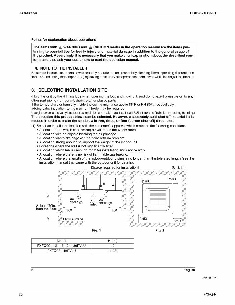
3. SELECTING INSTALLATION SITE⟨Hold the unit by the 4 lifting lugs when opening the box and moving it, and do not exert pressure on to any other part piping (refrigerant, drain, etc.) or plastic parts. If the temperature or humidity inside the ceiling might rise above 86°F or RH 80%, respectively,add extra insulation to the main unit bodyUse glass wool or polyethylene foam as insulation and make sure it is at least 3/8in. thick and fits inside the ceiling opening.⟩The direction this product blows can be selected. However, a separately sold shut-off material kit is needed in order to make the unit blow in two, three, or four (corner shut-off) directions.(1) Select an installation location with the customer’s approval which matches the following conditions.
• A location from which cool (warm) air will reach the whole room.• A location with no objects blocking the air passage.• A location where drainage can be done with no problem.• A location strong enough to support the weight of the indoor unit. • Locations where the wall is not significantly tilted.• A location which leaves enough room for installation and service work. • A location where there is no risk of flammable gas leaking. • A location where the length of the indoor-outdoor piping is no longer than the tolerated length (see the
installation manual that came with the outdoor unit for details).
The items with WARNING and CAUTION marks in the operation manual are the items per-taining to possibilities for bodily injury and material damage in addition to the general usage of the product. Accordingly, it is necessary that you make a full explanation about the described con-tents and also ask your customers to read the operation manual.
Model H (in.)
FXFQ09 · 12 · 18 · 24 · 30PVJU 10
FXFQ36 · 48PVJU 11-3/4
Fig. 2
[Space required for installation] (Unit: in.)
*≥60*≥60
*≥60*≥60
H
Floor surface
At least 70in. from the floor.
Airinlet
Fig. 1
≥60 ≥60
Airdischarge Air
discharge
20 FXFQ-P
EDUS391000-F1 Installation
3P161684-5H
English 7
CAUTION
• The indoor and outdoor units and the power supply wiring and remote controller cord must be installed at least 40in. away from any televisions or radios. This is to prevent interference with picture and sound reception. (Interference may occur even at 40in. away depending on the reception quality.)
• If installing the wireless kit, the distance of the signal sent from the remote controller might be shorter if there are fluorescent lights which are electrically started (such as with inverters, rapid starters, etc.) in the room. The indoor unit should be installed as far away from fluorescent lights as possible.
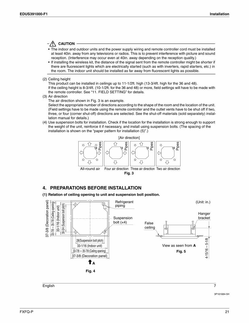
(2) Ceiling heightThis product can be installed in ceilings up to 11-1/2ft. high (13-3/4ft. high for the 36 and 48).If the ceiling height is 8-3/4ft. (10-1/2ft. for the 36 and 48) or more, field settings will have to be made with the remote controller. See “11. FIELD SETTING” for details.
(3) Air directionThe air direction shown in Fig. 3 is an example.Select the appropriate number of directions according to the shape of the room and the location of the unit. (Field settings have to be made using the remote controller and the outlet vents have to be shut off if two, three, or four (corner shut-off) directions are selected. See the shut-off materials (sold separately) instal-lation manual for details.)
(4) Use suspension bolts for installation. Check if the location for the installation is strong enough to support the weight of the unit, reinforce it if necessary, and install using suspension bolts. (The spacing of the installation is shown on the “paper pattern for installation (5)”.)
4. PREPARATIONS BEFORE INSTALLATION(1) Relation of ceiling opening to unit and suspension bolt position.
Pip
es
Pip
es
Pip
es
Pip
es
All-round air
[Air direction]
Two air directionThree air directionFour air directionFig. 3
37-3
/8 (D
ecor
atio
n pa
nel)
30-3/
4 (Su
spen
sion b
olt pi
tch)
33-1
/16
(Indo
or u
nit)
33-7/
8–35
-7/8 (
Ceilin
g ope
ning)
28(Suspension bolt pitch)
37-3/8 (Decoration panel)33-7/8 – 35-7/8 (Ceiling opening)
33-1/16 (Indoor unit)
Refrigerant piping
Suspensionbolt (×4)
Fig. 4
A
False ceiling
View as seen from A
Hangerbracket
4-15
/16
– 5-
1/8
Fig. 5
(Unit: in.)
FXFQ-P 21

Installation EDUS391000-F1
3P161684-5H
8 English
� Installation is possible when ceiling opening dimensions is as follows• When installing the unit within the frame for fixing false ceiling.
NOTE• Installation is possible with a ceiling dimension of 35-7/8in. (marked with *). However, to achieve a ceiling-
panel overlapping dimension of 13/16in., the spacing between the ceiling and the unit should be 1-3/8in. or less.
(2) Make the ceiling opening needed for installation where applicable. (For existing ceilings)• Refer to the paper pattern for installation (5) for ceiling opening dimensions.• Create the ceiling opening required for installation. From the side of the opening to the casing outlet,
implement the refrigerant and drain piping and wiring for remote controller (unnecessary for wireless type) and indoor-outdoor unit casing outlet. Refer to “6. REFRIGERANT PIPING WORK”, “7. DRAIN PIPING WORK” and “8. ELECTRIC WIRING WORK”.
• After making an opening in the ceiling, it may be necessary to reinforce ceiling beams to keep the ceiling level and to prevent it from vibrating. Consult the builder for details.
(3) Install the suspension bolts.(Use either a M8~M10 size bolt or the equivalent)Use a hole-in anchor for existing ceilings, and a sunken insert, sunken anchor or other field sup-plied parts for new ceilings to reinforce the ceiling to bear the weight of the unit. Adjust clearance (2-4in.) from the ceiling before proceeding further.
NOTE• All the above parts are field supplied.
(Dim
ensio
n ins
ide fr
ame)
33-1/16
35-7
/8
35-7/8(Dimension inside frame)
33-1
/16
Fig. 6
33-7/8(Opening dimension inside the flame for ceiling)Frame
≥13/16 33-7/8 – *35-7/8
(Ceiling-paneloverlapping dimension)
False ceiling
(Ceiling opening dimension)≥13/16
Fig. 7
(Unit: in.)
Ceiling material
1-3/8
Fig. 8
≥ 1-3/8≥
(Unit: in.)
2-4
Ceiling slab
Suspension boltLong nut or turn-buckleAnchor
False ceiling
<installation example>
Fig. 9
(Unit: in.)
22 FXFQ-P

EDUS391000-F1 Installation
3P161684-5H
English 9
5. INDOOR UNIT INSTALLATIONInstalling optional accessories (except for the decoration panel) before installing the indoor unit is easier. However, for existing ceilings, install fresh air inlet component kit and branch duct before installing the unit.As for the parts to be used for installation work, be sure to use the provided accessories and specified parts designated by our company.
(1) For new ceilings(1-1)Install the indoor unit temporarily.
• Attach the hanger bracket to the suspension bolt. Be sure to fix it securely by using a nut and washer (3) from the upper and lower sides of the hanger bracket.The washer fixing plate (7) will prevent the washer from falling.
(1-2)Refer to the paper pattern for installation (5) for ceiling opening dimension.Consult the builder or carpenter for details.• The center of the ceiling opening is indicated on the paper pattern for installation.
The center of the unit is indicated on the triangular mark to the unit bottom and on the paper pattern for installation.
• Fix the paper pattern to the unit with screws (6) (×4).• Ceiling height is shown on the side of the paper pattern for installation (5). Adjust the height of the unit
according to this indication.Please perform one of the following, as the shape of the paper pattern for installation differs accord-ing to the model.
Field supply
Washer (3) (accessory)
Hanger bracket
Tighten(double nuts)
Fig. 10
[Securing the hanger bracket]
Insert
Washer fixing plate (7)
[Securing the washer]
(accessory)
Fig. 11
Paper pattern for installation (5)
[Installation of paper pattern for installation]
Center of ceiling opening
Screw (6)(accessory)
Screw (6)(accessory)
Center of main unit
Center mark of main unit
Fig. 12
FXFQ-P 23

Installation EDUS391000-F1
3P161684-5H
10 English
<Ceiling work>(1-3)Adjust the unit to the right position for installation.
(Refer to “4. PREPARATIONS BEFORE INSTALLATION-(1)”.)• Using the Installation guide (15) allows you to check the positions from the underside of the unit to the lower ceiling surface.
(1-4)Check the unit is horizontally level.• The indoor unit is equipped with a built-in drain pump and float
switch. Verify that it is level by using a level or a water-filled vinyl tube.
CAUTION
If the unit is tilted against condensate flow, the float switch may malfunction and cause water to drip.
(1-5)Remove the washer fixing plate (7) used for preventing the washer from falling and tighten the upper nut.
(1-6)Remove the paper pattern for installation (5).
(2) For existing ceilings(2-1)Install the indoor unit temporarily.
Perform step (1-1) in (1) For new ceilings.(2-2)Adjust the height and position of the unit.
(Refer to “4. PREPARATIONS BEFORE INSTALLATION-(1)” and (1-3) in (1) For new ceilings.)(2-3)Perform steps (1-4), (1-5) in (1) For new ceilings.
6. REFRIGERANT PIPING WORK⟨For refrigerant piping of outdoor units, see the installation manual attached to the outdoor unit.⟩ ⟨Execute heat insulation work completely on both sides of the gas piping and the liquid piping. Otherwise, a water leakage can result sometimes.⟩
e⟨Also, in cases where the temperature and humidity of the refrigerant piping sections might exceed 86°F or RH80%, reinforce the refrigerant insulation. (13/16in. or thicker) Condensate may form on the surface of the insulating material.⟩⟨Be sure to check the type of R410A refrigerant to be used before doing any work. (Using an incorrect refrig-erant will prevent normal operation of the unit.)⟩
Apply the short side of the cut-out section.
Lower ceiling surface
Installation guide (15)(accessory)
Underside of the unit
Level Vinyl tube
[Maintaining horizontality]
Fig. 13
24 FXFQ-P

EDUS391000-F1 Installation
3P161684-5H
English 11
CAUTION• Use a pipe cutter and flare suitable for the type of refrigerant.• Apply ester oil or ether oil around the flare section before connecting.• To prevent dust, moisture or other foreign matter from infiltrating the tube, either pinch the end or cover
it with tape.• Do not allow anything other than the designated refrigerant to get mixed into the refrigerant circuit, such
as air, etc. If any refrigerant gas leaks while working on the unit, ventilate the room thoroughly right away.
• Do not mix air or other gas with the specified refrigerant in the refrig-eration cycle.
• Ventilate the room if refrigerant gas leaks during the work.• The outdoor unit is charged with refrigerant.• Be sure to use both a spanner and torque wrench together, as shown in the
drawing, when connecting or disconnecting pipes to/from the unit.(Refer to Fig. 14)
• Refer to “Table 3” for the dimensions of flare nut spaces.
• When connecting the flare nut, apply ester oil or ether oil to the flare section (outside only), and spin 3-4 times before screwing in.(Refer to Fig. 15)
• Keep all the screw mounting resin parts (e.g., piping presser plates) away from oil.If oil adheres, the strength of the screw mounting resin parts may drop.
CAUTION
Over-tightening the flare nut may break it and/or cause the refrigerant to leak.
NOTE• Use the flare nut included with the unit main body.
Table 3
• Refer to “Table 3” to determine the proper tightening torque.
Pipe size Tightening torque Flare dimensions A (in.) Flare shape
φ 1/4 10.4 – 12.7lbf·ft. 0.342 – 0.358
φ 3/8 24.1 – 29.4lbf·ft. 0.504 – 0.520
φ 1/2 36.5 – 44.5lbf·ft. 0.638 – 0.654
φ 5/8 45.6 – 55.6lbf·ft. 0.760 – 0.776
Torque wrench
Spanner
Pipe union
Flare nut
Fig. 14
Fig. 15
Coat here with ester or ether oil.
A
450 ± 2
0
R0.016-0.031
900± 2
0
FXFQ-P 25
Installation EDUS391000-F1
3P161684-5H
12 English
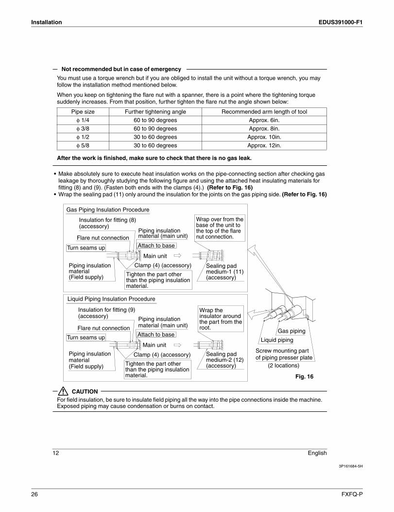
Not recommend but in case of emergency
You must use a torque wrench but if you are obliged to install the unit without a torque wrench, you mayfollow the installation method mentioned below.
When you keep on tightening the flare nut with a spanner, there is a point where the tightening torque suddenly increases. From that position, further tighten the flare nut the angle shown below:
After the work is finished, make sure to check that there is no gas leak.
• Make absolutely sure to execute heat insulation works on the pipe-connecting section after checking gas leakage by thoroughly studying the following figure and using the attached heat insulating materials for fitting (8) and (9). (Fasten both ends with the clamps (4).) (Refer to Fig. 16)
• Wrap the sealing pad (11) only around the insulation for the joints on the gas piping side. (Refer to Fig. 16)
CAUTIONFor field insulation, be sure to insulate field piping all the way into the pipe connections inside the machine.Exposed piping may cause condensation or burns on contact.
Pipe size Further tightening angle Recommended arm length of tool
φ 1/4 60 to 90 degrees Approx. 6in.
φ 3/8 60 to 90 degrees Approx. 8in.
φ 1/2 30 to 60 degrees Approx. 10in.
φ 5/8 30 to 60 degrees Approx. 12in.
Screw mounting part of piping presser plate
(2 locations)
Liquid piping
Gas piping
Fig. 16
Gas Piping Insulation Procedure
Insulation for fitting (8) (accessory)
Turn seams up
Turn seams up
Flare nut connection
Insulation for fitting (9) (accessory)
Flare nut connection
Attach to base
Attach to base
Main unit
Main unit
Piping insulation material (Field supply)
Piping insulation material (Field supply)
Tighten the part other than the piping insulation material.
Wrap over from the base of the unit to the top of the flare nut connection.
Wrap the insulator around the part from the root.
Sealing pad medium-1 (11) (accessory)
Sealing pad medium-2 (12) (accessory)
Clamp (4) (accessory)
Tighten the part other than the piping insulation material.
Clamp (4) (accessory)
Liquid Piping Insulation Procedure
Piping insulation material (main unit)
Piping insulation material (main unit)
26 FXFQ-P
EDUS391000-F1 Installation
3P161684-5H
English 13
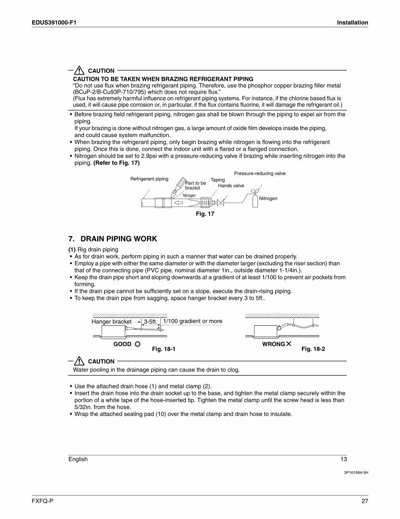
CAUTIONCAUTION TO BE TAKEN WHEN BRAZING REFRIGERANT PIPING“Do not use flux when brazing refrigerant piping. Therefore, use the phosphor copper brazing filler metal (BCuP-2/B-Cu93P-710/795) which does not require flux.”(Flux has extremely harmful influence on refrigerant piping systems. For instance, if the chlorine based flux is used, it will cause pipe corrosion or, in particular, if the flux contains fluorine, it will damage the refrigerant oil.)
• Before brazing field refrigerant piping, nitrogen gas shall be blown through the piping to expel air from the piping.If you brazing is done without nitrogen gas, a large amount of oxide film develops inside the piping, and could cause system malfunction.
• When brazing the refrigerant piping, only begin brazingpiping. Once this is done, connect the indoor unit with a flared
• Nitrogen should be set to 2.9psi with a pressure-reducing valve if brazing while inserting nitrogen into the piping. (Refer to Fig. 17)
7. DRAIN PIPING WORK(1) Rig drain piping• As for drain work, perform piping in such a manner that water can be drained properly.• Employ a pipe with either the same diameter or with the diameter larger (excluding the r section) than
that of the connecting pipe (PVC pipe, nominal diameter 1in., outside diameter 1-1/4in.).• Keep the drain pipe short and sloping downwards at a gradient of at least 1/100 to prevent air pockets from
forming.• If the drain pipe cannot be sufficiently set on a slope, execute the drain ng piping.• To keep the drain pipe from sagging, space hanger bracket every 3 to 5ft..
CAUTIONWater pooling in the drainage piping can cause the drain to clog.
• Use the attached drain hose (1) and metal clamp (2).• Insert the drain hose into the drain socket up to the base, and tighten the metal clamp securely within the
portion of a white tape of the hose-inserted tip. Tighten the metal clamp until the screw head is less than 5/32in. from the hose.
• Wrap the attached sealing pad (10) over the metal clamp and drain hose to insulate.
Nitrogen
Pressure-reducing valve
Hands valveTapingRefrigerant piping
Part to bebrazed
Nitrogen
Fig. 17
1/100 gradient or more3-5ft.
Fig. 18-1GOOD
Hanger bracket
Fig. 18-2WRONG
FXFQ-P 27
Installation EDUS391000-F1
3P161684-5H
14 English
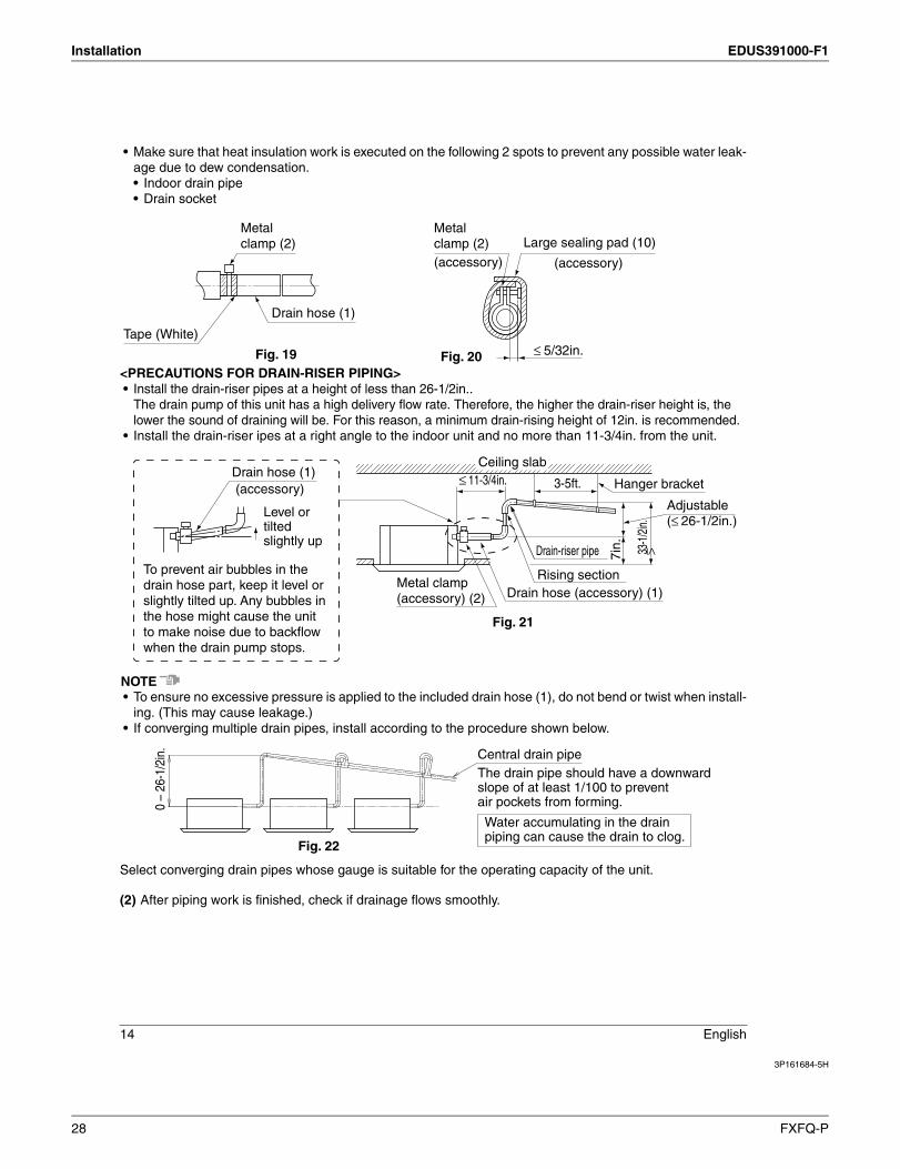
• Make sure that heat insulation work is executed on the following 2 spots to prevent any possible water leak-age due to dew condensation.• Indoor drain pipe• Drain socket
<PRECAUTIONS FOR DRAIN P ING>• Install the drain ris pipes at a height of less than 26-1/2in..
The drain pump of this unit has a high delivery flow rate. Therefore, the higher the drain r height is, the lower the sound of draining will be. For this reason, a minimum drain ri ing height of 12in. is recommended.
• Install the drain r s ipes at a right angle to the indoor unit and no more than 11-3/4in. from the unit.
NOTE• To ensure no excessive pressure is applied to the included drain hose (1), do not bend or twist when install-
ing. (This may cause leakage.)• If converging multiple drain pipes, install according to the procedure shown below.
Select converging drain pipes whose gauge is suitable for the operating capacity of the unit.
(2) After piping work is finished, check if drainage flows smoothly.
Metalclamp (2)
Tape (White)
Drain hose (1)
Fig. 19
Metalclamp (2) Large sealing pad (10)
(accessory) (accessory)
5/32in.Fig. 20 ≥
Ceiling slab
Metal clamp (accessory) (2)
Drain hose (1) (accessory)
Drain ris pipe
Rising sectionDrain hose (accessory) (1)
33-1
/2in.
Hanger bracket
Adjustable ( 26-1/2in.)
3-5ft.11-3/4in.
7in.
Fig. 21
≥
≥
≥
To prevent air bubbles in the drain hose part, keep it level or slightly tilted up. Any bubbles in the hose might cause the unit to make noise due to backflow when the drain pump stops.
Level or tiltedslightly up
0 –
26-1
/2in
.
Fig. 22
Water accumulating in the drain piping can cause the drain to clog.
Central drain pipeThe drain pipe should have a downward slope of at least 1/100 to prevent air pockets from forming.
28 FXFQ-P
EDUS391000-F1 Installation
3P161684-5H
English 15
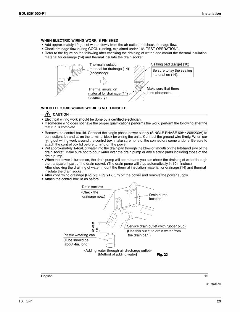
WHEN ELECTRIC WIRING WORK IS FINISHED• Add approximately 1/4gal. of water slowly from the air outlet and check drainage flow.• Check drainage flow during COOL running, explained under ‘‘12. TEST OPERATION’’.• Refer to the figure on the following after checking the draining of water, and mount the thermal insulation
material for drainage (14) and thermal insulate the drain socket.
WHEN ELECTRIC WIRING WORK IS NOT FINISHED
CAUTION• Electrical wiring work should be done by a certified electrician.• If someone who does not have the proper qualifications performs the work, perform the following after the
test run is complete.
• Remove the control box lid. Connect the single phase power supply (SINGLE PHASE 60Hz 208/230V) to connections L1 and L2 on the terminal block for wiring the units. Connect the ground wire firmly. When car-rying out wiring work around the control box, make sure none of the connectors come undone. Be sure to attach the control box lid before turning on the power.
• Put approximately 1/4gal. of water into the drain pan through the blow-off mouth on the left-hand side of the drain socket. Make sure not to pour water over the drain pump or any electric parts including those of the drain pump.
• When the power is turned on, the drain pump will operate and you can check the draining of water through the transparent part of the drain socket. (The drain pump will stop automatically in 10 minutes.)After checking the draining of water, mount the thermal insulation material for drainage (14) and thermal insulate the drain socket.
• After confirming drainage (Fig. 23, Fig. 24), turn off the power and remove the power supply. • Attach the control box lid as before.
Thermal insulation material for drainage (14) (accessory)
Sealing pad (Large) (10)
Thermal insulation material for drainage (14) (accessory)
Make sure that there is no clearance.
Be sure to lay the sealing material on (14).
At le
ast
4in.
Plastic watering can(Tube should be about 4in. long.)
(Check the drainage now.)
Service drain outlet (with rubber plug)(Use this outlet to drain water from the drain pan.)
Drain sockets
<Adding water through air discharge outlet>[Method of adding water] Fig. 23
Drain pump location
FXFQ-P 29
Installation EDUS391000-F1
3P161684-5H
16 English
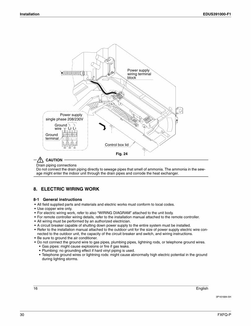
CAUTIONDrain piping connectionsDo not connect the drain piping directly to sewage pipes that smell of ammonia. The ammonia in the sew-age might enter the indoor unit through the drain pipes and corrode the heat exchanger.
8. ELECTRIC WIRING WORK
8-1 General instructions• All field supplied parts and materials and electric works must conform to local codes.• Use copper wire only.• For electric wiring work, refer to also “WIRING DIAGRAM” attached to the unit body.• For remote controller wiring details, refer to the installation manual attached to the remote controller.• All wiring must be performed by an authorized electrician.• A circuit breaker capable of shutting down power supply to the entire system must be installed.• Refer to the installation manual attached to the outdoor unit for the size of power supply electric wire con-
nected to the outdoor unit, the capacity of the circuit breaker and switch, and wiring instructions.• Be sure to ground the air conditioner.• Do not connect the ground wire to gas pipes, plumbing pipes, lightning rods, or telephone ground wires.
• Gas pipes: might cause explosions or fire if gas leaks.• Plumbing: no grounding effect if hard vinyl piping is used. • Telephone ground wires or lightning rods: might cause abnormally high electric potential in the ground
during lighting storms.
Fig. 24
Control box lid
Groundterminal
Power supply wiring terminal block
Power supply single phase 208/230V
L2 L1Groundwire
30 FXFQ-P
EDUS391000-F1 Installation
3P161684-5H
English 17
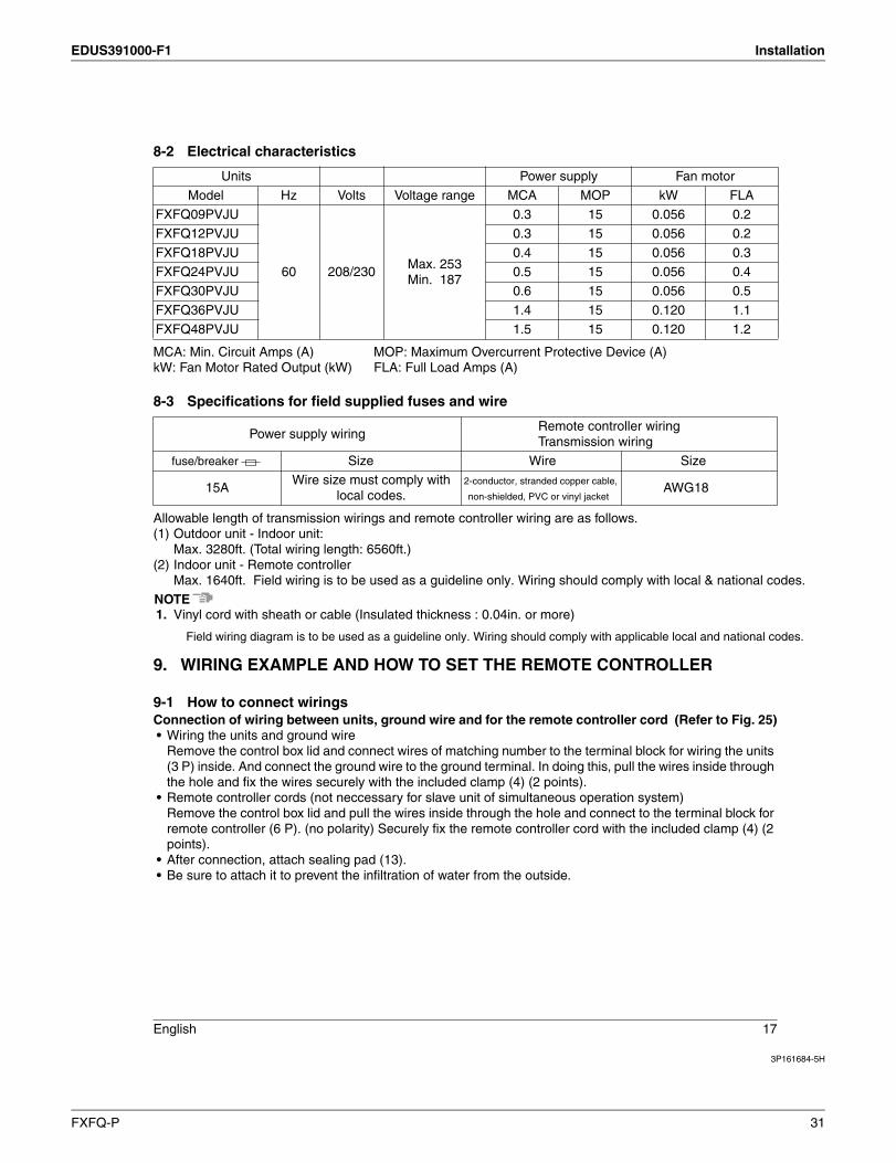
8-2 Electrical characteristics
MCA: Min. Circuit Amps (A) MOP: Maximum Overcurrent Protective Device (A)kW: Fan Motor Rated Output (kW) FLA: Full Load Amps (A)
8-3 Specifications for field supplied fuses and wire
Allowable length of transmission wirings and remote controller wiring are as follows.(1) Outdoor unit - Indoor unit:
Max. 3280ft. (Total wiring length: 6560ft.)(2) Indoor unit - Remote controller
Max. 1640ft.
NOTE1. Vinyl cord with sheath or cable (Insulated thickness : 0.04in. or more)
9. WIRING EXAMPLE AND HOW TO SET THE REMOTE CONTROLLER
9-1 How to connect wiringsConnection of wiring between units, ground wire and for the remote controller cord (Refer to Fig. 25)• Wiring the units and ground wire
Remove the control box lid and connect wires of matching number to the terminal block for wiring the units (3 P) inside. And connect the ground wire to the ground terminal. In doing this, pull the wires inside through the hole and fix the wires securely with the included clamp (4) (2 points).
• Remote controller cords (not neccessary for slave unit of simultaneous operation system)Remove the control box lid and pull the wires inside through the hole and connect to the terminal block for remote controller (6 P). (no polarity) Securely fix the remote controller cord with the included clamp (4) (2 points).
• After connection, attach sealing pad (13).• Be sure to attach it to prevent the infiltration of water from the outside.
Units Power supply Fan motor
Model Hz Volts Voltage range MCA MOP kW FLA
FXFQ09PVJU
60 208/230Max. 253Min. 187
0.3 15 0.056 0.2
FXFQ12PVJU 0.3 15 0.056 0.2
FXFQ18PVJU 0.4 15 0.056 0.3
FXFQ24PVJU 0.5 15 0.056 0.4
FXFQ30PVJU 0.6 15 0.056 0.5
FXFQ36PVJU 1.4 15 0.120 1.1
FXFQ48PVJU 1.5 15 0.120 1.2
Power supply wiringRemote controller wiringTransmission wiring
Wire
15AWire size must comply with
local codes.AWG18
Field wiring diagram is to be used as a guideline only. Wiring should comply with applicable local and national codes.
FXFQ-P 31
Installation EDUS391000-F1
3P161684-5H
18 English
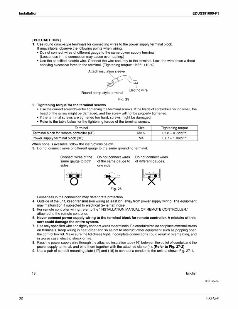
[ PRECAUTIONS ]1. Use round crimp-style terminals for connecting wires to the power supply terminal block.
If unavailable, observe the following points when wiring.• Do not connect wires of different gauge to the same power supply terminal.
(Looseness in the connection may cause overheating.)• Use the specified electric wire. Connect the wire securely to the terminal. Lock the wire down without
applying excessive force to the terminal. (Tightening torque: 1lbf·ft. ±10 %)
2. Tightening torque for the terminal screws.• Use the correct screwdriver for tightening the terminal screws. If the blade of screwdriver is too small, the
head of the screw might be damaged, and the screw will not be properly tightened.• If the terminal screws are tightened too hard, screws might be damaged.• Refer to the table below for the tightening torque of the terminal screws.
When none is available, follow the instructions below.3. Do not connect wires of different gauge to the same grounding terminal.
Looseness in the connection may deteriorate protection.4. Outside of the unit, keep transmission wiring at least 2in. away from power supply wiring. The equipment
may malfunction if subjected to electrical (external) noise.5. For remote controller wiring, refer to the “INSTALLATION MANUAL OF REMOTE CONTROLLER.”
attached to the remote controller.6. Never connect power supply wiring to the terminal block for remote controller. A mistake of th
sort could damage the entire system.7. Use only specified wire and tightly connect wires to terminals. Be careful wires do not place external stress
on terminals. Keep wiring in neat order and so as not to obstruct other equipment such as popping open the control box lid. Make sure the lid closes tight. Incomplete connections could result in overheating, and in worse case, electric shock or fire.
8. Pass the power supply wire through the attached insulation tube (16) between the outlet of conduit and the power supply terminal, and bind them together with the attached clamp (4). (Refer to Fig. 27-2)
9. Use a pair of conduit mounting plate (17) and (18) to connect a conduit to the unit as shown Fig. 27-1.
Terminal Size Tightening torque
Terminal block for remote controller (6P) M3.5 0.58 – 0.72lbf·ft
Power supply terminal block (3P) M4 0.87 – 1.06lbf·ft
Fig. 25
Electric wireRound crimp-style terminal
Attach insulation sleeve
Connect wires of the same gauge to both side .
Do not connect wires of the same gauge to one side.
Do not connect wires of different gauges.
Fig. 26
32 FXFQ-P

EDUS391000-F1 Installation
3P161684-5H
English 19
10. Use a 90° elbow type of conduit with dimensions Fig. 27-1 to prevent it from hitting the swing motor hous-ing of decoration panel.
Observe the notes mentioned below when wiring to the terminal block for wiring the units.
Fig. 27-1
Conduit
<1-3/8
≥3/8Conduit mountingplate (17)
Conduit mountingplate (18)
Fig. 27-2
Sheaths
Remote controller wiring (low voltage)
3/8 – 5/8in.2-3/4 – 3-1/2in.
Clamp (4)
Approximately1/4in.Peel back the sheath on the power line and twist. Length of
sheath to peel back
Cut off any excess material after tightening.
Wiring through-holes
Terminal blockfor remotecontroller
Control box lid
(P1 • P2)
Wiring diagram(Backside of control box lid)
Remotecontrollerwiring
Power supply terminal block
Insulationtube (16)
(3P)
Remotecontroller wiring
Forced off
Transmission wiring
Transmission wiring
P1 P2 F1 F2 T1 T2
Power supply and ground wire sheath
Clamping position
Secure the ground wire power supply and with both edges aligned.
Clamp (4)
Cut off any excess material after tightening the power supply wiring and ground wire together.Ground terminal
(Len
gth
of sh
eath
to p
eel b
ack)
3/8~
5/8i
n.
3~4i
n. L2 L1
<<Power supply and ground wire (high voltage)>>
Power supply and ground wire
Conduit mounting plate (17) (18)
Insulationtube (16)
Electric insulation
FXFQ-P 33
Installation EDUS391000-F1
3P161684-5H
20 English
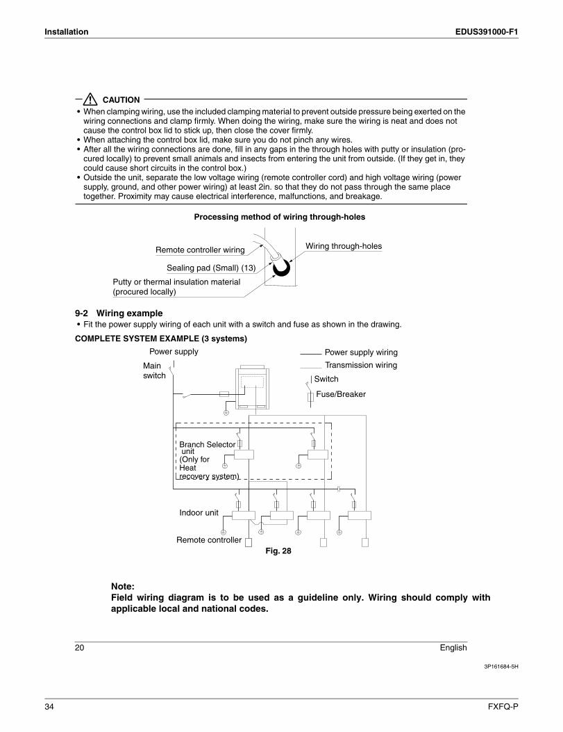
CAUTION• When clamping wiring, use the included clamping material to prevent outside pressure being exerted on the
wiring connections and clamp firmly. When doing the wiring, make sure the wiring is neat and does not cause the control box lid to stick up, then close the cover firmly.
• When attaching the control box lid, make sure you do not pinch any wires.• After all the wiring connections are done, fill in any gaps in the through holes with putty or insulation (pro-
cured locally) to prevent small animals and insects from entering the unit from outside. (If they get in, they could cause short circuits in the control box.)
• Outside the unit, separate the low voltage wiring (remote controller cord) and high voltage wiring (power supply, ground, and other power wiring) at least 2in. so that they do not pass through the same place together. Proximity may cause electrical interference, malfunctions, and breakage.
9-2 Wiring example• Fit the power supply wiring of each unit with a switch and fuse as shown in the drawing.
COMPLETE SYSTEM EXAMPLE (3 systems)
Remote controller wiring
Sealing pad (Small) (13)
Putty or thermal insulation material(procured locally)
Wiring through-holes
Processing method of wiring through-holes
Power supply wiring
Transmission wiring
Switch
Fuse
Power supply
Mainswitch
Remote controller
Indoor unit
B S unit(Only forHeatrecovery system)
Fig. 28
Note: Field wiring diagram is to be used as a guideline only. Wiring should comply withapplicable local and national codes.
34 FXFQ-P
EDUS391000-F1 Installation
3P161684-5H
English 21
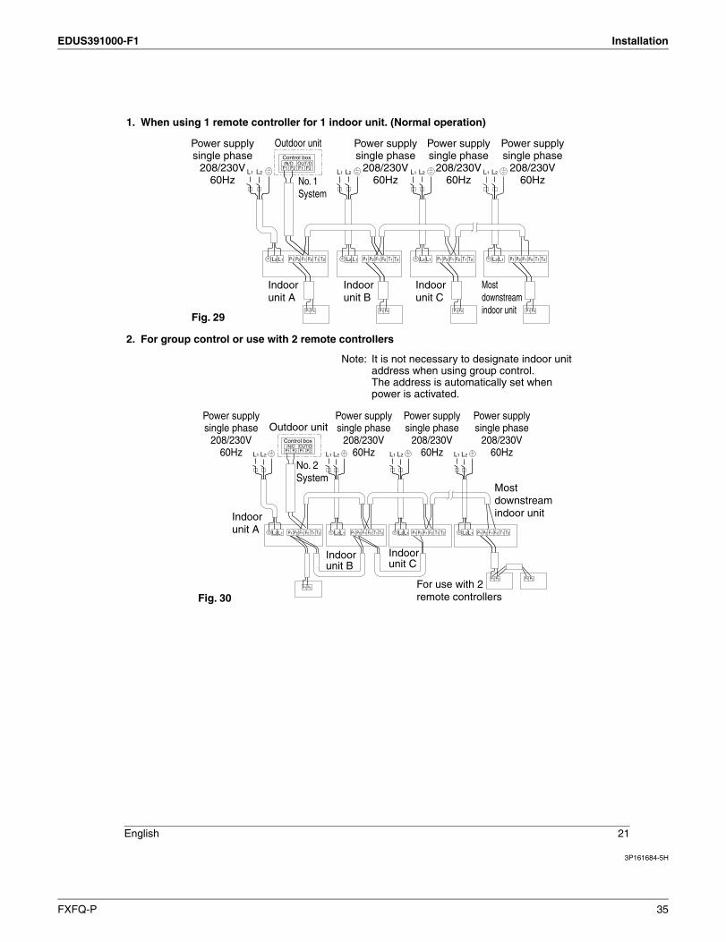
1. When using 1 remote controller for 1 indoor unit. (Normal operation)
2. For group control or use with 2 remote controllers
L1 L2 L1 L2
IN/D OUT/DF1 F2 F1 F2
Control box
L1 L2
P1 P2
P1 P2
F1 F2 T1 T2 P1 P2
P1 P2
F1 F2 T1 T2 P1 P2
P1 P2
F1 F2 T1 T2 P1 P2
P1 P2
F1 F2 T1 T2
L1 L2
Outdoor unit
No. 1System
Indoorunit A
Fig. 29
Indoorunit B
Indoorunit C
Mostdownstreamindoor unit
Power supplysingle phase
208/230V60Hz
Power supplysingle phase
208/230V60Hz
Power supplysingle phase
208/230V60Hz
Power supplysingle phase
208/230V60Hz
L2 L1 L2 L1 L2 L1 L2 L1
L1 L2 L1 L2 L1 L2
Note: It is not necessary to designate indoor unit address when using group control. The address is automatically set when power is activated.
Control box
Outdoor unit
No. 2 System
Indoorunit A
Fig. 30
Indoorunit B
Indoorunit C
Mostdownstreamindoor unit
For use with 2remote controllers
IN/D OUT/DF1 F2 F1 F2
P1 P2
P1 P2
F1 F2 T1 T2 P1 P2 F1 F2 T1 T2 P1 P2 F1 F2 T1 T2 P1 P2 F1 F2 T1 T2
P1 P2P1 P2
L2L1 L2L1 L2L1 L2L1
Power supplysingle phase
208/230V60Hz
Power supplysingle phase
208/230V60Hz
Power supplysingle phase
208/230V60Hz
Power supplysingle phase
208/230V60HzL1 L2
FXFQ-P 35

Installation EDUS391000-F1
3P161684-5H
22 English
3. When including B S unit
[ PRECAUTIONS ]1. Do not ground the equipment on gas pipes, water pipes or lightning rods, or crossground with telephones.
Improper grounding could result in electric shock.
9-3 Control by 2 remote controllers (controlling 1 indoor unit by 2 remote controllers)• When using 2 remote controllers, one must be set to “MAIN” and the other to “SUB”.
MAIN/SUB CHANGEOVER• The settings of the BRC1E71 remote controller should be switched while referring to the manual supplied
with the remote controller.• In case of the BRC1D71 remote controller.(1) Insert a screwdriver into the recess between the upper and lower part of remote controller and, working
from the 2 positions, pry off the upper part. (The remote controller PC board is attached to the upper part of remote controller.) (Refer to Fig. 32)
(2) Turn the main/sub changeover switch on one of the two remote controller PC boards to “S”. (Leave the switch of the other remote controller set to “M”.) (Refer to Fig. 33)
IN/D OUT/DF1 F2 F1 F2
IN/DOUT/DF1 F2 F1 F2
L1 L2
P1 P2
P1 P2 F1 F2 T1 T2
B S unitNo. 3System
Outdoor unit
Indoor unit A Mostdownstreamindoor unit
Fig. 31
Control box
Control boxIN/DOUT/D
F1 F2 F1 F2
B S unitControl box
L1 L2
P1 P2
P1 P2 F1 F2 T1 T2L2 L1 L2 L1
Power supplysingle phase
208/230V60Hz
Power supplysingle phase
208/230V60Hz
Upper part of remote controller
Lower part of remote controller
Fig. 32Insert the screwdriver here and gently work off the upper part of remote controller.
36 FXFQ-P

EDUS391000-F1 Installation
3P161684-5H
English 23
Wiring Method (See ‘‘ELECTRIC WIRING WORK’’)
(3) Remove the control box lid(4) Add remote control 2 (slave) to the terminal block for remote controller (P1, P2) in the control box.
(There is no polarity.) (Refer to Fig. 30 and 8-3.)
9-4 Computerised control (forced off and on/off operation)(1) Wire specifications and how to perform wiring
• Connect the input from outside to terminals T1 and T2 of the terminal block for remote controller.
(2) Actuation• The following table explains FORCED OFF and ON/OFF OPERATIONS in response to Input A.
(3) How to select FORCED OFF and ON/OFF OPERATION• Turn the power on and then use the remote controller to select operation.
9-5 Centralized control• For centralized control, it is necessary to designate the group No. For details, refer to the manual of each
optional controllers for centralized control.
Wire specification
Gauge AWG18
Length Max. ft.
External terminal Contact that can ensure the minimum applicable load of 15 V DC, 1 mA.
FORCED OFF ON/OFF OPERATION
Input “ON” stops operation (impossible by remote controllers.) Input OFF → ON turns ON unit.
Input OFF enables control by remote controller. Input ON → OFF turns OFF unit.
S
MS
SM
RemotecontrollerPC board
(Factory setting)
Fig. 33
Only one remote controller needs to be changed if factory settings have remained unto ched.
F2 T1 T2
FORCEDOFF
Input A
FXFQ-P 37
Installation EDUS391000-F1
3P161684-5H
24 English
10. INSTALLATION OF THE DECORATION PANELCaution:With a wireless remote controller, field setting and test operation cannot be performed without attach-ing the decoration panel.<If performing a test run without attaching the decoration panel, read “11. FIELD SETTING” and “12. TEST OPERATION” first.>Refer to the installation manual attached to the decoration panel.After installing the decoration panel, ensure that there is no space between the unit body and decoration panel.Note:Since the electric insulation sheet sticked to the control box lid gets sandwiched between the unit body and decoration panel, when closing the lid, slip the insulation sheet between them first and then attach the lid to the control box.
11. FIELD SETTING
CAUTIONWhen performing field setting or test operation without attaching the decoration panel, do not touch the drain pump. This may cause electric shock.
• Check that the outdoor unit has been wired properly.
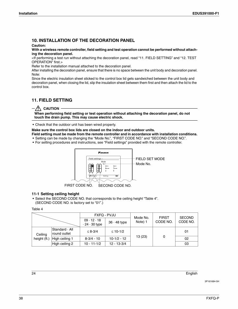
Make sure the control box lids are closed on the indoor and outdoor units.Field setting must be made from the remote controller and in accordance with installation conditions.• Setting can be made by changing the “Mode No.”, “FIRST CODE NO.” and “SECOND CODE NO.”.• For setting procedures and instructions, see “Field settings” provided with the remote controller.
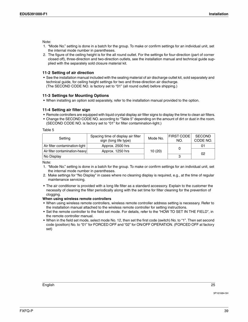
11-1 Setting ceiling height• Select the SECOND CODE NO. that corresponds to the ceiling height “Table 4”.
(SECOND CODE NO. is factory set to “01”.)
Table 4
FXFQ - PVJUMode No.Note) 1
FIRSTCODE NO.
SECONDCODE NO.09 · 12 · 18
· 24 · 30 type36 · 48 type
Ceiling height (ft.)
Standard · All round outlet
≤ 8-3/4 ≤ 10-1/2
13 (23) 0
01
High ceiling 1 8-3/4 - 10 10-1/2 - 12 02
High ceiling 2 10 - 11-1/2 12 - 13-3/4 03
Mode No.FIELD SET MODE
SECOND CODE NO.FIRST CODE NO.
Mode10
Field settings
0–014–––8–––
Return Setting
38 FXFQ-P
EDUS391000-F1 Installation
3P161684-5H
English 25
Note:1. “Mode No.” setting is done in a batch for the group. To make or confirm settings for an individual unit, set
the internal mode number in parentheses.2. The figure of the ceiling height is for the all round outlet. For the settings for four-direction (part of corner
closed off), three-direction and two-direction outlets, see the installation manual and technical guide sup-plied with the separately sold closure material kit.
11-2 Setting of air direction• See the installation manual included with the sealing material of air discharge outlet kit, sold separately and
technical guide, for ceiling height settings for two and three-direction air discharge. (The SECOND CODE NO. is factory set to “01” (all round outlet) before shipping.)
11-3 Settings for Mounting Options• When installing an option sold separately, refer to the installation manual provided to the option.
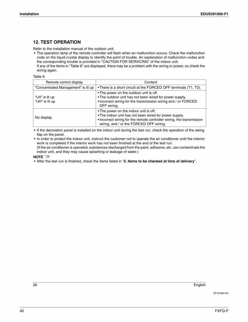
11-4 Setting air filter sign• Remote controllers are equipped with liquid crystal display air filter signs to display the time to clean air filters.• Change the SECOND CODE NO. according to “Table 5” depending on the amount of dirt or dust in the room.
(SECOND CODE NO. is factory set to “01” for filter contamination-light.)
Table 5
Note:1. “Mode No.” setting is done in a batch for the group. To make or confirm settings for an individual unit, set
the internal mode number in parentheses.2. Make settings for “No Display” in cases where no cleaning display is required, e.g., at the time of regular
maintenance servicing.
• The air conditioner is provided with a long life filter as a standard accessory. Explain to the customer the necessity of cleaning the filter periodically along with the set time for filter cleaning for the prevention of clogging.
When using wireless remote controllers• When using wireless remote controllers, wireless remote controller address setting is necessary. Refer to
the installation manual attached to the wireless remote controller for setting instructions.• Set the remote controller to the field set mode. For details, refer to the “HOW TO SET IN THE FIELD”, in
the remote controller manual.• When in the field set mode, select mode No. 12, then set the first code (switch) No. to “1”. Then set second
code (position) No. to “01” for FORCED OFF and “02” for ON/OFF OPERATION. (FORCED OFF at factory set)
SettingSpacing time of display air filter
sign (long life type)Mode No.
FIRST CODE NO.
SECONDCODE NO.
Air filter contamination-light Approx. 2500 hrs
10 (20)0
01
Air filter contamination-heavy Approx. 1250 hrs02
No Display 3
FXFQ-P 39
Installation EDUS391000-F1
3P161684-5H
26 English
12. TEST OPERATIONRefer to the installation manual of the outdoor unit.• The operation lamp of the remote controller will flash when an malfunction occurs. Check the malfunction
code on the liquid crystal display to identify the point of trouble. An explanation of malfunction codes and the corresponding trouble is provided in “CAUTION FOR SERVICING” of the indoor unit.If any of the items in “Table 6” are displayed, there may be a problem with the wiring or power, so check the wiring again.
Table 6
• If the decoration panel is installed on the indoor unit during the test run, check the operation of the swing flap on the panel.
• In order to protect the indoor unit, instruct the customer not to operate the air conditioner until the interior work is completed if the interior work has not been finished at the end of the test run.(If the air conditioner is operated, substances discharged from the paint, adhesive, etc. can contaminate the indoor unit, and they may cause splashing or leakage of water.)
NOTE• After the test run is finished, check the items listed in “2. Items to be checked at time of delivery”.
Remote control display Content
“Concentrated Management” is lit up • There is a short circuit at the FORCED OFF terminals (T1, T2).
“U4” is lit up“UH” is lit up
• The power on the outdoor unit is off.• The outdoor unit has not been wired for power supply.• Incorrect wiring for the transmission wiring and / or FORCED OFF wiring.
No display
• The power on the indoor unit is off.• The indoor unit has not been wired for power supply.• Incorrect wiring for the remote controller wiring, the transmission wiring, and / or the FORCED OFF wiring.
40 FXFQ-P
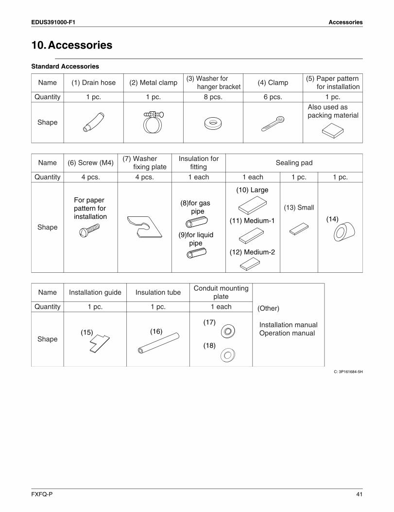
EDUS391000-F1 Accessories
10.Accessories
Standard Accessories
C: 3P161684-5H
Name (1) Drain hose (2) Metal clamp(3) Washer for
hanger bracket(4) Clamp
(5) Paper pattern for installation
Quantity 1 pc. 1 pc. 8 pcs. 6 pcs. 1 pc.
Shape
Also used as packing material
Name (6) Screw (M4)(7) Washer
fixing plateInsulation for
fittingSealing pad
Quantity 4 pcs. 4 pcs. 1 each 1 each 1 pc. 1 pc.
Shape
(13) Small
Name Installation guide Insulation tubeConduit mounting
plate
(Other)
Installation manualOperation manual
Quantity 1 pc. 1 pc. 1 each
Shape
For paper pattern for installation
(8)for gas pipe
(9)for liquid pipe
(11) Medium-1
(12) Medium-2
(10) Large
(14)
(15) (16)(17)
(18)
FXFQ-P 41

Accessories EDUS391000-F1
Optional Accessories (For Unit)
Optional Accessories (For Controls): Refer to booklet of “Controls”.
ModelFXFQ9PVJU FXFQ12PVJU FXFQ18PVJU FXFQ24PVJU FXFQ30PVJU FXFQ36PVJU FXFQ48PVJU
Item
Decoration panel BYCP125K-W1
Sealing member of air discharge outlet KDBH55K160F
Panel spacer KDBP55H160FA
Filter related
Replacement long life filter
Non-woven type KAFP551K160
Fresh air intake kit Chamber type
Without T-joint pipe and fan
KDDP55B160
With T-joint pipe without fanKDDP55B160K
Branch duct chamber KDJP55B80 KDJP55B160
Chamber connection kit KKSJ55KA160
C: 3D070526A
42 FXFQ-P
1645 Wallace Drive, Suite 110Carrollton, TX75006
AMERICAS
dddddfdf
ISO 9001 is a plant certification systemdefined by the International Organizationfor Standardization (ISO) relating to quality assurance. ISO 9001 certificationcovers quality assurance aspects relatedto the “design, development, manufacture, installation, and supplementary service” of products manufactured at the plant.
ISO 14001 is the standard defined by theInternational Organization for Standardization(ISO) relating to environmental managementsystems. Our group has been acknowledged byan internationally accredited program of environmental protection procedures and activities to meet the requirements of ISO 14001.
Specifications, designs and other content appearing in this brochure are current as of March 2011 but subject to change without notice.
EDUS391000-F1Printed in U.S.A. 3/2011 B AK
©2010 Daikin Industries, Limited.
Daikin® AC Absolute Comfort®, and its design, VRV®, REFNET™, and Quaternity™ are registered trademarks of Daikin Industries, Limited. All rights reserved. LonWorks® and LON® are registered trademarks of Echelon Corporation. BACnet® is a Data Communication Protocal for Building Automation and Control Networks, developed under the auspices of the American Society of Heating, Refrigeratin, and Air-Conditioning Engineers (ASHRAE).
Daikin Industries, Ltd.’s products are manufactured for export to numerous countries throughout theworld. Daikin Industries, Ltd. does not have control over which products are exported to and used in aparticular country. Prior to purchase, please therefore confirm with your local authorized importer,distributor and/or retailer whether this product conforms tot he applicable standards, and is suitable foruse, in the region where the product will be used. This statement does not purport to exclude, restrict ormodify the application of any local legislation.
Ask a qualified installer or contractor to install this product. Do not try to install the product yourself.Improper installation can result in water or refrigerant leakage, electrical shock, fire, or explosion.
Use only those parts and accessories supplied or specified by Daikin. Ask a qualified installer orcontractor to install those parts and accessories. Use of unauthorized parts and accessories or improper installation of parts and accessories can result in water or refrigerant leakage, electrical shock, fire, or explosion.
Read the User’s Manual carefully before using this product. The User’s Manual provides importantsafety instructions and warnings. Be sure to follow these instructions and warnings.
If you have any inquiries, please contact your local importer, distributor, or retailer.