g-709 itu_t
DESCRIPTION
OTN conceptTRANSCRIPT
7/16/2019 G-709 ITU_T
http://slidepdf.com/reader/full/g-709-itut 1/218
I n t e r n a t i o n a l T e l e c o m m u n i c a t i o n U n i o n
ITU-T G.709/Y.1331TELECOMMUNICATIONSTANDARDIZATION SECTOROF ITU
(12/2009)
SERIES G: TRANSMISSION SYSTEMS AND MEDIA,DIGITAL SYSTEMS AND NETWORKS
Digital terminal equipments – General
SERIES Y: GLOBAL INFORMATIONINFRASTRUCTURE, INTERNET PROTOCOL ASPECTS
AND NEXT-GENERATION NETWORKS
Internet protocol aspects – Transport
Interfaces for the Optical Transport Network(OTN)
Recommendation ITU-T G.709/Y.1331
7/16/2019 G-709 ITU_T
http://slidepdf.com/reader/full/g-709-itut 2/218
ITU-T G-SERIES RECOMMENDATIONS
TRANSMISSION SYSTEMS AND MEDIA, DIGITAL SYSTEMS AND NETWORKS
INTERNATIONAL TELEPHONE CONNECTIONS AND CIRCUITS G.100–G.199
GENERAL CHARACTERISTICS COMMON TO ALL ANALOGUE CARRIER-TRANSMISSION SYSTEMS
G.200–G.299
INDIVIDUAL CHARACTERISTICS OF INTERNATIONAL CARRIER TELEPHONESYSTEMS ON METALLIC LINES G.300–G.399
GENERAL CHARACTERISTICS OF INTERNATIONAL CARRIER TELEPHONE SYSTEMSON RADIO-RELAY OR SATELLITE LINKS AND INTERCONNECTION WITH METALLICLINES
G.400–G.449
COORDINATION OF RADIOTELEPHONY AND LINE TELEPHONY G.450–G.499
TRANSMISSION MEDIA AND OPTICAL SYSTEMS CHARACTERISTICS G.600–G.699
DIGITAL TERMINAL EQUIPMENTS G.700–G.799
General G.700–G.709
Coding of voice and audio signals G.710–G.729
Principal characteristics of primary multiplex equipment G.730–G.739
Principal characteristics of second order multiplex equipment G.740–G.749
Principal characteristics of higher order multiplex equipment G.750–G.759
Principal characteristics of transcoder and digital multiplication equipment G.760–G.769Operations, administration and maintenance features of transmission equipment G.770–G.779
Principal characteristics of multiplexing equipment for the synchronous digital hierarchy G.780–G.789
Other terminal equipment G.790–G.799
DIGITAL NETWORKS G.800–G.899
DIGITAL SECTIONS AND DIGITAL LINE SYSTEM G.900–G.999
MULTIMEDIA QUALITY OF SERVICE AND PERFORMANCE – GENERIC AND USER-RELATED ASPECTS
G.1000–G.1999
TRANSMISSION MEDIA CHARACTERISTICS G.6000–G.6999
DATA OVER TRANSPORT – GENERIC ASPECTS G.7000–G.7999
PACKET OVER TRANSPORT ASPECTS G.8000–G.8999
ACCESS NETWORKS G.9000–G.9999
For further details, please refer to the list of ITU-T Recommendations.
7/16/2019 G-709 ITU_T
http://slidepdf.com/reader/full/g-709-itut 3/218
Rec. ITU-T G.709/Y.1331 (12/2009) i
Recommendation ITU-T G.709/Y.1331
Interfaces for the Optical Transport Network (OTN)
Summary
Recommendation ITU-T G.709/Y.1331 defines the requirements for the optical transport module of
order n (OTM-n) signals of the optical transport network, in terms of:
– optical transport hierarchy (OTH);
– functionality of the overhead in support of multi-wavelength optical networks;
– frame structures;
– bit rates; – formats for mapping client signals.
The first revision of this Recommendation includes the text of Amendment 1 (ODUk virtual
concatenation, ODUk multiplexing, backward IAE), extension of physical interface specification,
ODUk APS/PCC signal definition and several editorial enhancements.
The second revision of this Recommendation includes the text of Amendments 1, 2, 3, Corrigenda 1,
2, Erratum 1, Implementers Guide, support for an extended (unlimited) set of constant bit rate client
signals, a flexible ODUk, which can have any bit rate and a bit rate tolerance up to ±100 ppm, a
client/server independent generic mapping procedure to map a client signal into the payload of an
OPUk, or to map an ODUj signal into the payload of one or more tributary slots in an OPUk, ODUk
delay measurement capability.
History
Edition Recommendation Approval Study Group
1.0 ITU-T G.709/Y.1331 2001-02-09 15
1.1 ITU-T G.709/Y.1331 (2001) Amend. 1 2001-11-29 15
2.0 ITU-T G.709/Y.1331 2003-03-16 152.1 ITU-T G.709/Y.1331 (2003) Amend. 1 2003-12-14 15
2.2 ITU-T G.709/Y.1331 (2003) Cor. 1 2006-12-14 15
2.3 ITU-T G.709/Y.1331 (2003) Amend. 2 2007-11-22 15
2.4 ITU-T G.709/Y.1331 (2003) Cor.2 2009-01-13 15
2.5 ITU-T G.709/Y.1331 (2003) Amend. 3 2009-04-22 15
3.0 ITU-T G.709/Y.1331 2009-12-22 15
7/16/2019 G-709 ITU_T
http://slidepdf.com/reader/full/g-709-itut 4/218
ii Rec. ITU-T G.709/Y.1331 (12/2009)
FOREWORD
The International Telecommunication Union (ITU) is the United Nations specialized agency in the field of
telecommunications, information and communication technologies (ICTs). The ITU Telecommunication
Standardization Sector (ITU-T) is a permanent organ of ITU. ITU-T is responsible for studying technical,
operating and tariff questions and issuing Recommendations on them with a view to standardizingtelecommunications on a worldwide basis.
The World Telecommunication Standardization Assembly (WTSA), which meets every four years,
establishes the topics for study by the ITU-T study groups which, in turn, produce Recommendations on
these topics.
The approval of ITU-T Recommendations is covered by the procedure laid down in WTSA Resolution 1.
In some areas of information technology which fall within ITU-T's purview, the necessary standards are
prepared on a collaborative basis with ISO and IEC.
NOTE
In this Recommendation, the expression "Administration" is used for conciseness to indicate both a
telecommunication administration and a recognized operating agency.
Compliance with this Recommendation is voluntary. However, the Recommendation may contain certain
mandatory provisions (to ensure e.g. interoperability or applicability) and compliance with the
Recommendation is achieved when all of these mandatory provisions are met. The words "shall" or some
other obligatory language such as "must" and the negative equivalents are used to express requirements. The
use of such words does not suggest that compliance with the Recommendation is required of any party.
INTELLECTUAL PROPERTY RIGHTS
ITU draws attention to the possibility that the practice or implementation of this Recommendation may
involve the use of a claimed Intellectual Property Right. ITU takes no position concerning the evidence,
validity or applicability of claimed Intellectual Property Rights, whether asserted by ITU members or others
outside of the Recommendation development process.
As of the date of approval of this Recommendation, ITU had received notice of intellectual property,
protected by patents, which may be required to implement this Recommendation. However, implementers
are cautioned that this may not represent the latest information and are therefore strongly urged to consult the
TSB patent database at http://www.itu.int/ITU-T/ipr/.
ITU 2010
All rights reserved. No part of this publication may be reproduced, by any means whatsoever, without the
prior written permission of ITU.
7/16/2019 G-709 ITU_T
http://slidepdf.com/reader/full/g-709-itut 5/218
Rec. ITU-T G.709/Y.1331 (12/2009) iii
CONTENTS
Page
1 Scope ............................................................................................................................ 1 2 References..................................................................................................................... 1 3 Terms and definitions ................................................................................................... 3
3.1 Terms defined elsewhere ................................................................................ 3 3.2 Terms defined in this Recommendation ......................................................... 4
4 Abbreviations ................................................................................................................ 4 5 Conventions .................................................................................................................. 8 6 Optical transport network interface structure ............................................................... 9
6.1 Basic signal structure ...................................................................................... 9 6.2 Information structure for the OTN interfaces ................................................. 11
7 Multiplexing/mapping principles and bit rates ............................................................. 15 7.1 Mapping .......................................................................................................... 17 7.2 Wavelength division multiplex ....................................................................... 18 7.3 Bit rates and capacity...................................................................................... 18 7.4 ODUk time-division multiplex ....................................................................... 22
8 Optical transport module (OTM-n.m, OTM-nr.m, OTM-0.m, OTM-0.mvn) .............. 27 8.1 OTM with reduced functionality (OTM-0.m, OTM-nr.m, OTM-0.mvn) ...... 28 8.2 OTM with full functionality (OTM-n.m) ....................................................... 32
9 Physical specification of the ONNI .............................................................................. 34 9.1 OTM-0.m ........................................................................................................ 34 9.2 OTM-nr.m ...................................................................................................... 34 9.3 OTM-n.m ........................................................................................................ 34 9.4 OTM-0.mvn .................................................................................................... 34
10 Optical channel (OCh) .................................................................................................. 34 10.1 OCh with full functionality (OCh) ................................................................. 34 10.2 OCh with reduced functionality (OChr) ......................................................... 35
11 Optical channel transport unit (OTU) ........................................................................... 35 11.1 OTUk frame structure ..................................................................................... 35 11.2 Scrambling ...................................................................................................... 36
12 Optical channel data unit (ODUk) ................................................................................ 37 12.1 ODUk frame structure .................................................................................... 37 12.2 ODUk bit rates and bit rate tolerances ........................................................... 37
13 Optical channel payload unit (OPUk)........................................................................... 40 14 OTM overhead signal (OOS) ....................................................................................... 40 15 Overhead description .................................................................................................... 41
15.1 Types of overhead .......................................................................................... 42 15.2 Trail trace identifier and access point identifier definition ............................ 43
7/16/2019 G-709 ITU_T
http://slidepdf.com/reader/full/g-709-itut 6/218
iv Rec. ITU-T G.709/Y.1331 (12/2009)
Page
15.3 OTS OH description ....................................................................................... 45 15.4 OMS OH description ...................................................................................... 46 15.5 OCh OH description ....................................................................................... 46 15.6 OTUk/ODUk frame alignment OH description ............................................. 47 15.7 OTUk OH description .................................................................................... 48 15.8 ODUk OH description .................................................................................... 51 15.9 OPUk OH description..................................................................................... 65
16 Maintenance signals...................................................................................................... 67 16.1 OTS maintenance signals ............................................................................... 68 16.2 OMS maintenance signals .............................................................................. 68 16.3 OCh maintenance signals ............................................................................... 68 16.4 OTUk maintenance signals ............................................................................. 68 16.5 ODUk maintenance signals ............................................................................ 70 16.6 Client maintenance signal ............................................................................... 71
17 Mapping of client signals ............................................................................................. 72 17.1 OPUk client signal fail (CSF) ......................................................................... 72 17.2 Mapping of CBR2G5, CBR10G, CBR10G3 and CBR40G signals into
OPUk .............................................................................................................. 73 17.3 Mapping of ATM cell stream into OPUk (k=0,1,2,3) .................................... 77 17.4 Mapping of GFP frames into OPUk ............................................................... 78 17.5 Mapping of test signal into OPUk .................................................................. 79 17.6 Mapping of a non-specific client bit stream into OPUk ................................. 81 17.7 Mapping of other constant bit-rate signals with justification into OPUk ....... 81 17.8 Mapping a 1000BASE-X and FC-1200 signal via timing transparent
transcoding into OPUk ................................................................................... 93 17.9 Mapping a supra-2.488 CBR Gbit/s signal into OPUflex .............................. 96
18 Concatenation ............................................................................................................... 97 18.1 Virtual concatenation of OPUk ...................................................................... 97 18.2 Mapping of client signals ............................................................................... 102 18.3 LCAS for virtual concatenation ...................................................................... 110
19 Mapping ODUj signals into the ODTU signal and the ODTU into the HO OPUk
tributary slots ................................................................................................................ 111 19.1 OPUk tributary slot definition ........................................................................ 111 19.2 ODTU definition ............................................................................................ 118 19.3 Multiplexing ODTU signals into the OPUk ................................................... 120 19.4 OPUk multiplex overhead and ODTU justification overhead ....................... 128 19.5 Mapping ODUj into ODTUjk ........................................................................ 139 19.6 Mapping of ODUj into ODTUk.ts.................................................................. 148
Annex A – Forward error correction using 16-byte interleaved RS(255,239) codecs ............ 153
7/16/2019 G-709 ITU_T
http://slidepdf.com/reader/full/g-709-itut 7/218
Rec. ITU-T G.709/Y.1331 (12/2009) v
Page
Annex B – Adapting 64B/66B encoded clients via transcoding into 513B code blocks ......... 155 B.1 Transmission order ......................................................................................... 155 B.2 Client frame recovery ..................................................................................... 155
B.3 Transcoding from 66B blocks to 513B blocks ............................................... 155 B.4 Link fault signalling ....................................................................................... 159
Annex C – Adaptation of OTU3 and OTU4 over multichannel parallel interfaces ................ 160 Annex D – Generic mapping procedure principles .................................................................. 163
D.1 Basic principle ................................................................................................ 163 D.2 Applying GMP in OTN .................................................................................. 166 D.3 Cm(t) encoding and decoding ......................................................................... 169 D.4 ΣCnD(t) encoding and decoding ...................................................................... 173
Appendix I – Range of stuff ratios for asynchronous mappings of CBR2G5, CBR10G,
and CBR40G clients with ±20 ppm bit-rate tolerance into OPUk, and for asynchronous multiplexing of ODUj into ODUk (k > j) .............................................. 174
Appendix II – Examples of functionally standardized OTU frame structures ........................ 180 Appendix III – Example of ODUk multiplexing ..................................................................... 183 Appendix IV – Example of fixed stuff in OPUk with multiplex of lower-order ODUk
signals ........................................................................................................................... 185 Appendix V .............................................................................................................................. 186 Appendix VI – ODUk multiplex structure identifier (MSI) examples .................................... 187 Appendix VII – Adaptation of parallel 64B/66B encoded clients ........................................... 189
VII.1 Introduction .................................................................................................... 189 VII.2 Clients signal format ....................................................................................... 189 VII.3 Client frame recovery ..................................................................................... 189 VII.4 Additions to Annex B transcoding for parallel 64B/66B clients .................... 192
Appendix VIII – Improved robustness for mapping of 40GBASE-R into OPU3 using
1027B code blocks ........................................................................................................ 195 VIII.1 Introduction .................................................................................................... 195 VIII.2 513B code block framing and flag bit protection ........................................... 195
VIII.3 66B block sequence check .............................................................................. 196 Appendix IX – Parallel logic implementation of the CRC-8 and CRC-5 ................................ 201 Appendix X – OTL4.10 structure ............................................................................................ 203 Appendix XI – CPRI into LO ODU mapping.......................................................................... 204 Appendix XII – Overview of CBR clients into LO OPU mapping types ................................ 206 Bibliography............................................................................................................................. 207

7/16/2019 G-709 ITU_T
http://slidepdf.com/reader/full/g-709-itut 8/218
7/16/2019 G-709 ITU_T
http://slidepdf.com/reader/full/g-709-itut 9/218
Rec. ITU-T G.709/Y.1331 (12/2009) 1
Recommendation ITU-T G.709/Y.1331
Interfaces for the Optical Transport Network (OTN)
1 Scope
The optical transport hierarchy (OTH) supports the operation and management aspects of opticalnetworks of various architectures, e.g., point-to-point, ring and mesh architectures.
This Recommendation defines the interfaces of the optical transport network to be used within and
between subnetworks of the optical network, in terms of:
– optical transport hierarchy (OTH);
– functionality of the overhead in support of multi-wavelength optical networks;
– frame structures;
– bit rates;
– formats for mapping client signals.
The interfaces defined in this Recommendation can be applied at user-to-network interfaces (UNI)
and network node interfaces (NNI) of the optical transport network. It is recognized, for interfaces
used within optical subnetworks, that aspects of the interface are optical technology dependent and
subject to change as technology progresses. Therefore, optical technology dependent aspects (for
transverse compatibility) are not defined for these interfaces to allow for technology changes. The
overhead functionality necessary for operations and management of optical subnetworks is defined.
The second revision of this Recommendation introduces:
– support for an extended (unlimited) set of constant bit rate client signals;
– a flexible ODUk, which can have any bit rate and a bit rate tolerance up to ±100 ppm;
– a client/server independent generic mapping procedure to map a client signal into the
payload of an OPUk, or to map an ODUj signal into the payload of one or more tributary
slots in an OPUk;
– ODUk delay measurement capability.
2 References
The following ITU-T Recommendations and other references contain provisions which, through
reference in this text, constitute provisions of this Recommendation. At the time of publication, the
editions indicated were valid. All Recommendations and other references are subject to revision;
users of this Recommendation are therefore encouraged to investigate the possibility of applying themost recent edition of the Recommendations and other references listed below. A list of the
currently valid ITU-T Recommendations is regularly published. The reference to a document within
this Recommendation does not give it, as a stand-alone document, the status of a Recommendation.
[ITU-T G.652] Recommendation ITU-T G.652 (2009), Characteristics of a single-mode
optical fibre and cable.
[ITU-T G.653] Recommendation ITU-T G.653 (2006), Characteristics of a dispersion-
shifted single-mode optical fibre and cable.
[ITU-T G.655] Recommendation ITU-T G.655 (2009), Characteristics of a non-zero
dispersion-shifted single-mode optical fibre and cable.
[ITU-T G.693] Recommendation ITU-T G.693 (2009), Optical interfaces for intra-office
systems.
7/16/2019 G-709 ITU_T
http://slidepdf.com/reader/full/g-709-itut 10/218
2 Rec. ITU-T G.709/Y.1331 (12/2009)
[ITU-T G.695] Recommendation ITU-T G.695 (2009), Optical interfaces for coarse
wavelength division multiplexing applications.
[ITU-T G.707] Recommendation ITU-T G.707/Y.1322 (2003), Network node interface
for the synchronous digital hierarchy (SDH).
[ITU-T G.780] Recommendation ITU-T G.780/Y.1351 (2008), Terms and definitions for
synchronous digital hierarchy (SDH) networks.[ITU-T G.798] Recommendation ITU-T G.798 (2006), Characteristics of optical
transport network hierarchy equipment functional blocks, plus
Amendment 1 (2008).
[ITU-T G.805] Recommendation ITU-T G.805 (2000), Generic functional architecture
of transport networks.
[ITU-T G.806] Recommendation ITU-T G.806 (2009), Characteristics of transport
equipment – Description methodology and generic functionality.
[ITU-T G.870] Recommendation ITU-T G.870/Y.1352 (2004), Terms and definitions for
optical transport networks (OTN).[ITU-T G.872] Recommendation ITU-T G.872 (2001), Architecture of optical transport
networks.
[ITU-T G.873.1] Recommendation ITU-T G.873.1 (2006), Optical Transport Network
(OTN): Linear protection.
[ITU-T G.959.1] Recommendation ITU-T G.959.1 (2009), Optical transport network
physical layer interfaces.
[ITU-T G.984.6] Recommendation ITU-T G.984.6 (2008), Gigabit-capable passive
optical networks (GPON): Reach extension, plus Amendment 1 (2009).
[ITU-T G.7041] Recommendation ITU-T G.7041/Y.1303 (2003), Generic framing procedure (GFP).
[ITU-T G.7042] Recommendation ITU-T G.7042/Y.1305 (2001), Link capacity
adjustment scheme (LCAS) for virtual concatenated signals.
[ITU-T G.8011.1] Recommendation ITU-T G.8011.1/Y.1307.1 (2009), Ethernet private
line service.
[ITU-T I.432.1] Recommendation ITU-T I.432.1 (1999), B-ISDN user-network
interface – Physical layer specification: General characteristics.
[ITU-T M.1400] Recommendation ITU-T M.1400 (2001), Designations for
interconnections among operators' networks.
[ITU-T M.3100 Amd.3] Recommendation ITU-T M.3100 (1995) Amd.3 (2001), Generic network
information model − Amendment 3: Definition of the management
interface for a generic alarm reporting control (ARC) feature.
[ITU-T O.150] Recommendation ITU-T O.150 (1996), General requirements for
instrumentation for performance measurements on digital transmission
equipment .
[ITU-T T.50] Recommendation ITU-T T.50 (1992), International Reference Alphabet
(IRA) (Formely International Alphabet No. 5 or IA5) – Information
technology – 7-bit coded character set for information interchange.
7/16/2019 G-709 ITU_T
http://slidepdf.com/reader/full/g-709-itut 11/218
Rec. ITU-T G.709/Y.1331 (12/2009) 3
[IEEE 802.3] IEEE Std. 802.3:2008, Information Technology – Local and Metropolitan
Area Networks Specific Requirement – Part 3: Carrier Sense Multiple
Access with Collision Detection (CSMA/CD) Access Method and
Physical Layer Specifications.
3 Terms and definitions
3.1 Terms defined elsewhere
This Recommendation uses the following terms defined elsewhere:
3.1.1 Terms defined in [ITU-T G.780]:
– BIP-X
– network node interface
3.1.2 Terms defined in [ITU-T G.805]:
– adapted information (AI)
– characteristic information (CI) – network
– subnetwork
3.1.3 Terms defined in [ITU-T G.870]:
– CBR10G
– CBR2G5
– CBR40G
– completely standardized OTUk (OTUk)
– connection monitoring end point (CMEP)
– functionally standardized OTUk (OTUkV)
– hitless activation/deactivation of a connection monitor
– inter-domain interface (IrDI)
– intra-domain interface (IaDI)
– link capacity adjustment scheme (LCAS)
– non associated overhead (naOH)
– OCC with full functionality (OCC)
– OCC with reduced functionality (OCCr)
– OCG with full functionality (OCG n)
– OCG with reduced functionality (OCG nr)
– ODUk path (ODUkP)
– ODUk TCM (ODUkT)
– optical carrier group of order n (OCG n[r])
– optical channel (OCh[r])
– optical channel carrier (OCC[r])
– optical channel data unit (ODUk)
– optical channel payload unit (OPUk) – optical channel transport unit (OTUk[V])
– optical channel with full functionality (OCh)
7/16/2019 G-709 ITU_T
http://slidepdf.com/reader/full/g-709-itut 12/218
4 Rec. ITU-T G.709/Y.1331 (12/2009)
– optical channel with reduced functionality (OChr)
– optical multiplex unit (OMU n, n ≥ 1)
– optical physical section of order n (OPSn)
– optical supervisory channel (OSC)
– optical transport hierarchy (OTH)
– optical transport module (OTM n[r].m)
– optical transport network (OTN)
– optical transport network node interface (ONNI)
– OTH multiplexing
– OTM overhead signal (OOS)
– OTM with full functionality (OTM n.m)
– OTM with reduced functionality (OTM-0.m, OTM-nr.m)
3.1.4 Terms defined in [ITU-T G.872]:
– optical multiplex section (OMS) – optical transmission section (OTS)
3.2 Terms defined in this Recommendation
None.
4 Abbreviations
This Recommendation uses the following abbreviations:
0xYY YY is a value in hexadecimal presentation
16FS 16 columns with Fixed Stuff
3R Reamplification, Reshaping and Retiming
ACT Activation (in the TCM ACT byte)
AI Adapted Information
AIS Alarm Indication Signal
AMP Asynchronous Mapping Procedure
API Access Point Identifier
APS Automatic Protection SwitchingBDI Backward Defect Indication
BDI-O Backward Defect Indication Overhead
BDI-P Backward Defect Indication Payload
BEI Backward Error Indication
BI Backward Indication
BIAE Backward Incoming Alignment Error
BIP Bit Interleaved Parity
BMP Bit-synchronous Mapping Procedure
Cm number of m-bit client data entities
7/16/2019 G-709 ITU_T
http://slidepdf.com/reader/full/g-709-itut 13/218
Rec. ITU-T G.709/Y.1331 (12/2009) 5
Cn number of n-bit client data entities
CnD difference between Cn and (m/n x Cm)
CAUI (Chip to) 100 Gb/s Attachment Unit Interface
CB Control Block
CBR Constant Bit RateCI Characteristic Information
CM Connection Monitoring
CMEP Connection Monitoring End Point
CMGPON_D Continuous Mode GPON Downstream
CMGPON_U2 Continuous Mode GPON Upstream 2
CMOH Connection Monitoring Overhead
CPRI Common Public Radio Interface
CRC Cyclic Redundancy Check
CS Client Specific
CSF Client Signal Fail
CTRL Control word sent from source to sink
DAPI Destination Access Point Identifier
DMp Delay Measurement of ODUk path
DMti Delay Measurement of TCMi
DNU Do Not UseEDC Error Detection Code
EOS End of Sequence
EXP Experimental
ExTI Expected Trace Identifier
FAS Frame Alignment Signal
FC Flag Continuation
FDI Forward Defect Indication
FDI-O Forward Defect Indication Overhead
FDI-P Forward Defect Indication Payload
FEC Forward Error Correction
GCC General Communication Channel
GID Group Identification
GMP Generic Mapping Procedure
GPON Gigabit-capable Passive Optical Networks
IaDI Intra-Domain InterfaceIAE Incoming Alignment Error
IrDI Inter-Domain Interface

7/16/2019 G-709 ITU_T
http://slidepdf.com/reader/full/g-709-itut 14/218
6 Rec. ITU-T G.709/Y.1331 (12/2009)
JC Justification Control
JOH Justification Overhead
LCAS Link Capacity Adjustment Scheme
LF Local Fault
LLM Logical Lane Marker LSB Least Significant Bit
MFAS MultiFrame Alignment Signal
MFI Multiframe Indicator
MS Maintenance Signal
MSB Most Significant Bit
MSI Multiplex Structure Identifier
MST Member Status
naOH non-associated overhead
NJO Negative Justification Opportunity
NNI Network Node Interface
NORM Normal Operating Mode
OCC Optical Channel Carrier
OCCo Optical Channel Carrier – overhead
OCCp Optical Channel Carrier – payload
OCCr Optical Channel Carrier with reduced functionalityOCG Optical Carrier Group
OCGr Optical Carrier Group with reduced functionality
OCh Optical channel with full functionality
OChr Optical channel with reduced functionality
OCI Open Connection Indication
ODTUG Optical channel Data Tributary Unit Group
ODTUjk Optical channel Data Tributary Unit j into k
ODTUk.ts Optical channel Data Tributary Unit k with ts tributary slots
ODU Optical channel Data Unit
ODUk Optical channel Data Unit-k
ODUk-Xv X virtually concatenated ODUks
ODUkP Optical channel Data Unit-k Path monitoring level
ODUkT Optical channel Data Unit-k Tandem connection monitoring level
OH Overhead
OMFI OPU Multi-Frame Identifier OMS Optical Multiplex Section
OMS-OH Optical Multiplex Section Overhead
7/16/2019 G-709 ITU_T
http://slidepdf.com/reader/full/g-709-itut 15/218
Rec. ITU-T G.709/Y.1331 (12/2009) 7
OMU Optical Multiplex Unit
ONNI Optical Network Node Interface
OOS OTM Overhead Signal
OPS Optical Physical Section
OPSM Optical Physical Section MultilaneOPU Optical channel Payload Unit
OPUk Optical channel Payload Unit-k
OPUk-Xv X virtually concatenated OPUks
OSC Optical Supervisory Channel
OTH Optical Transport Hierarchy
OTL Optical channel Transport Lane
OTLC Optical Transport Lane Carrier
OTLCG Optical Transport Lane Carrier Group
OTM Optical Transport Module
OTN Optical Transport Network
OTS Optical Transmission Section
OTS-OH Optical Transmission Section Overhead
OTU Optical channel Transport Unit
OTUk completely standardized Optical channel Transport Unit-k
OTUkV functionally standardized Optical channel Transport Unit-k OTUk-v Optical channel Transport Unit-k with vendor specific OTU FEC
P-CMEP Path-Connection Monitoring End Point
PCC Protection Communication Channel
PCS Physical Coding Sublayer
PJO Positive Justification Opportunity
PLD Payload
PM Path Monitoring
PMA Physical Medium Attachment sublayer
PMI Payload Missing Indication
PMOH Path Monitoring Overhead
PN Pseudo-random Number
POS Position field
ppm parts per million
PRBS Pseudo Random Binary Sequence
PSI Payload Structure Identifier PT Payload Type
RES Reserved for future international standardization
7/16/2019 G-709 ITU_T
http://slidepdf.com/reader/full/g-709-itut 16/218
8 Rec. ITU-T G.709/Y.1331 (12/2009)
RF Remote Fault
RS Reed-Solomon
RS-Ack Re-sequence acknowledge
SAPI Source Access Point Identifier
Sk Sink SM Section Monitoring
SMOH Section Monitoring OverHead
So Source
SNC Subnetwork Connection
SNC/I Subnetwork Connection protection with Inherent monitoring
SNC/N Subnetwork Connection protection with Non-intrusive monitoring
SNC/S Subnetwork Connection protection with Sublayer monitoring
SQ Sequence Indicator
TC Tandem Connection
TC-CMEP Tandem Connection-Connection Monitoring End Point
TCM Tandem Connection Monitoring
TCMOH Tandem Connection Monitoring Overhead
TS Tributary Slot
TSOH Tributary Slot Overhead
TTT Timing Transparent TranscodingTxTI Transmitted Trace Identifier
UNI User-to-Network Interface
VCG Virtual Concatenation Group
VCOH Virtual Concatenation Overhead
vcPT virtual concatenated Payload Type
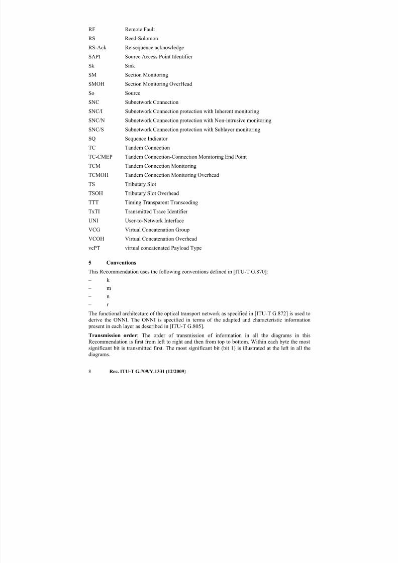
5 Conventions
This Recommendation uses the following conventions defined in [ITU-T G.870]: – k
– m
– n
– r
The functional architecture of the optical transport network as specified in [ITU-T G.872] is used to
derive the ONNI. The ONNI is specified in terms of the adapted and characteristic information
present in each layer as described in [ITU-T G.805].
Transmission order: The order of transmission of information in all the diagrams in this
Recommendation is first from left to right and then from top to bottom. Within each byte the mostsignificant bit is transmitted first. The most significant bit (bit 1) is illustrated at the left in all the
diagrams.
7/16/2019 G-709 ITU_T
http://slidepdf.com/reader/full/g-709-itut 17/218
Rec. ITU-T G.709/Y.1331 (12/2009) 9
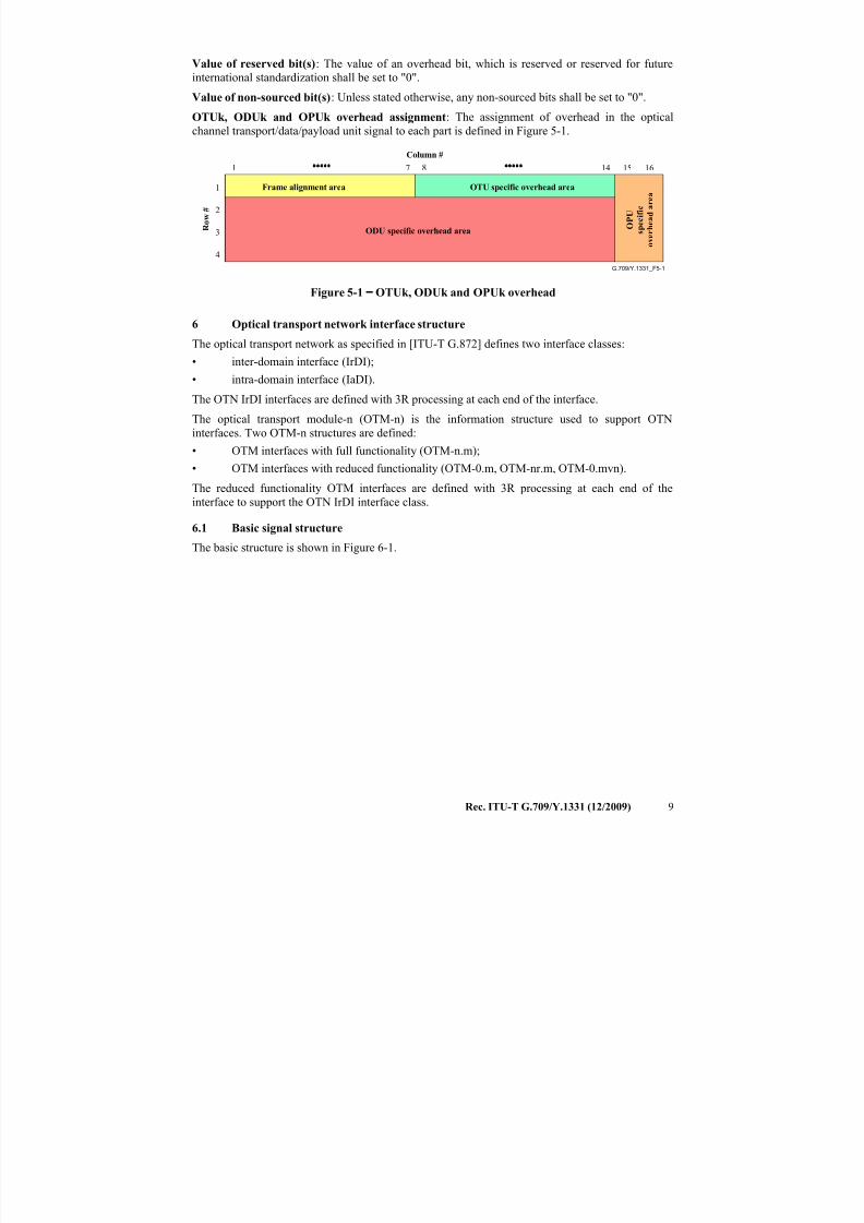
Value of reserved bit(s): The value of an overhead bit, which is reserved or reserved for future
international standardization shall be set to "0".
Value of non-sourced bit(s): Unless stated otherwise, any non-sourced bits shall be set to "0".
OTUk, ODUk and OPUk overhead assignment: The assignment of overhead in the optical
channel transport/data/payload unit signal to each part is defined in Figure 5-1.
G.709/Y.1331_F5-1
R o w #
Column #
Frame alignment area OTU specific overhead area
ODU specific overhead area O P U
s p e c i f i c
o v e r h e a d a r e a
1
2
3
4
1 167 14 158
Figure 5-1−
OTUk, ODUk and OPUk overhead
6 Optical transport network interface structure
The optical transport network as specified in [ITU-T G.872] defines two interface classes:
• inter-domain interface (IrDI);
• intra-domain interface (IaDI).
The OTN IrDI interfaces are defined with 3R processing at each end of the interface.
The optical transport module-n (OTM-n) is the information structure used to support OTN
interfaces. Two OTM-n structures are defined:
• OTM interfaces with full functionality (OTM-n.m);
• OTM interfaces with reduced functionality (OTM-0.m, OTM-nr.m, OTM-0.mvn).
The reduced functionality OTM interfaces are defined with 3R processing at each end of the
interface to support the OTN IrDI interface class.
6.1 Basic signal structure
The basic structure is shown in Figure 6-1.
7/16/2019 G-709 ITU_T
http://slidepdf.com/reader/full/g-709-itut 18/218
10 Rec. ITU-T G.709/Y.1331 (12/2009)
LO ODUk
OTM-0.mvn
Clients (e.g. STM-N, ATM, IP, Ethernet, MPLS, ...)
LO OPUk
ODUkP
ODUkT O C h
s u
b s t r u c
t u r e
HO ODUk
OTUkV
OMSn
OTSn
OTUk
OPSn
HO OPUk
OCh
ODUkP
ODUkT
OTM-n.m OTM-0.m,OTM-nr.m
Reducedfunctionality
OTM interface
Fullfunctionality
OTM interface
OTUk
OPSMnk
OTUkV OTUk
OChr
Multi Lane,Reduced
functionalityOTM interface
OTM-0.mvn
OTUkV
OMSn
OTSn
OTUk
OPSn
OCh
OTM-n.m OTM-0.m,OTM-nr.m
Reducedfunctionality
OTM interface
Fullfunctionality
OTM interface
OTUk
OPSMnk
OTUkV OTUk
OChr
Multi Lane,Reduced
functionalityOTM interface
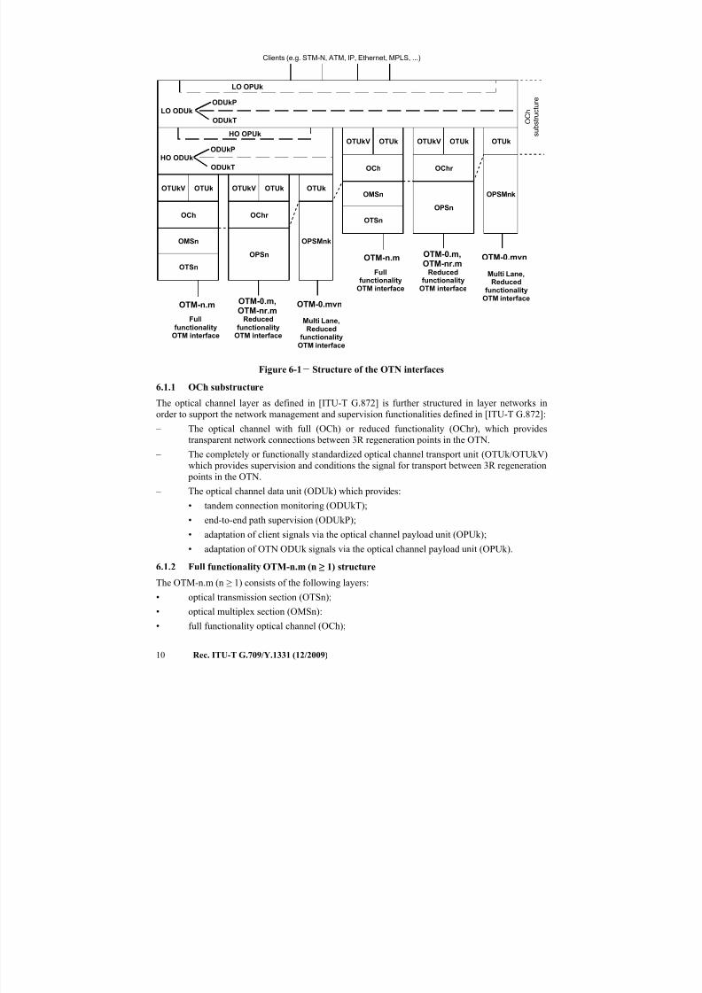
Figure 6-1 − Structure of the OTN interfaces
6.1.1 OCh substructure
The optical channel layer as defined in [ITU-T G.872] is further structured in layer networks in
order to support the network management and supervision functionalities defined in [ITU-T G.872]:
– The optical channel with full (OCh) or reduced functionality (OChr), which provides
transparent network connections between 3R regeneration points in the OTN.
– The completely or functionally standardized optical channel transport unit (OTUk/OTUkV)
which provides supervision and conditions the signal for transport between 3R regeneration
points in the OTN.
– The optical channel data unit (ODUk) which provides:
• tandem connection monitoring (ODUkT);
• end-to-end path supervision (ODUkP);
• adaptation of client signals via the optical channel payload unit (OPUk);
• adaptation of OTN ODUk signals via the optical channel payload unit (OPUk).
6.1.2 Full functionality OTM-n.m (n ≥ 1) structure
The OTM-n.m (n ≥ 1) consists of the following layers:
• optical transmission section (OTSn);
• optical multiplex section (OMSn):
• full functionality optical channel (OCh);
7/16/2019 G-709 ITU_T
http://slidepdf.com/reader/full/g-709-itut 19/218
Rec. ITU-T G.709/Y.1331 (12/2009) 11
• completely or functionally standardized optical channel transport unit (OTUk/OTUkV);
• one or more optical channel data unit (ODUk).
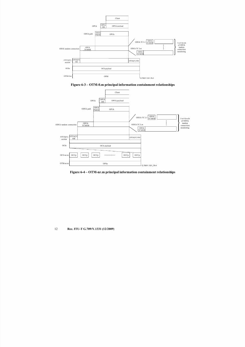
6.1.3 Reduced functionality OTM-nr.m and OTM-0.m structure
The OTM-nr.m and OTM-0.m consist of the following layers:
• optical physical section (OPSn);
• reduced functionality optical channel (OChr);
• completely or functionally standardized optical channel transport unit (OTUk/OTUkV);
• one or more optical channel data unit (ODUk).
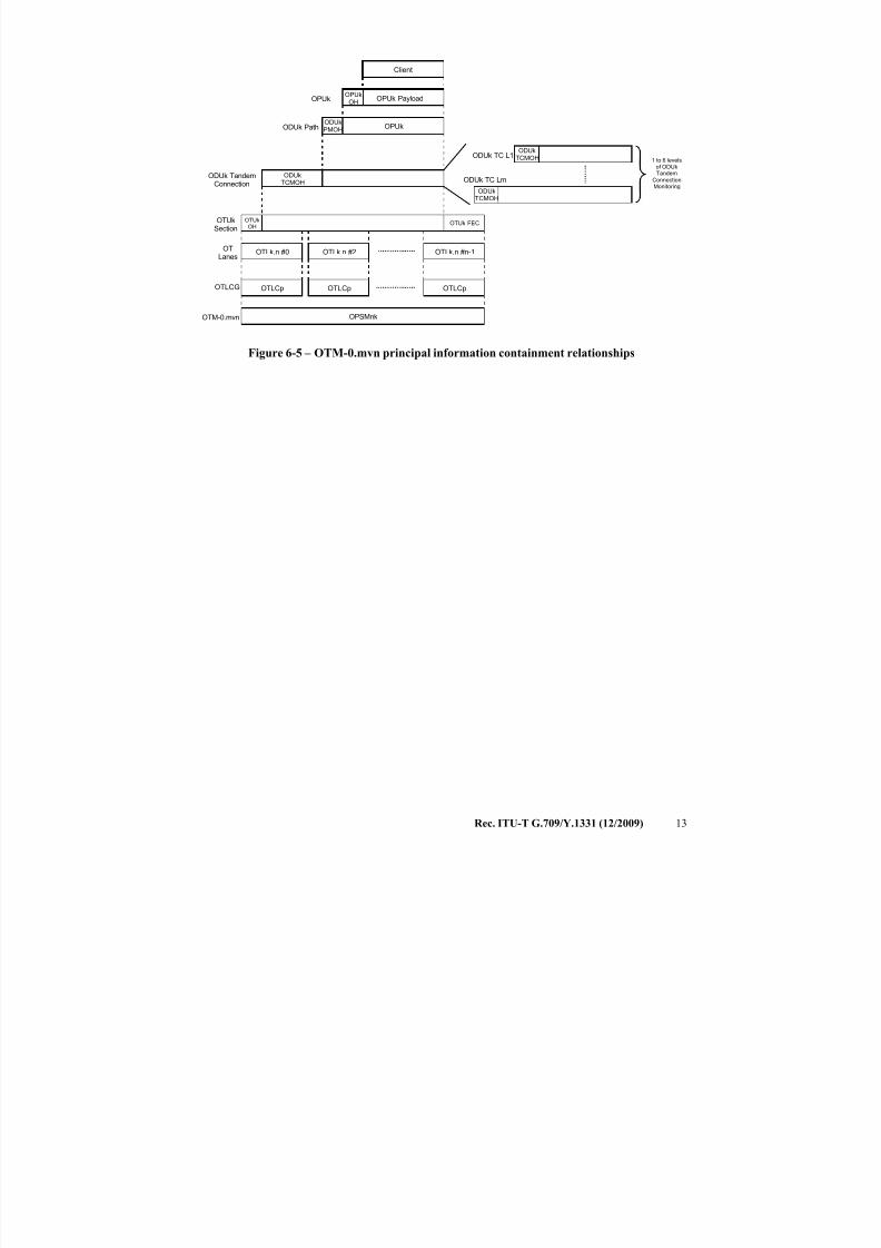
6.1.4 Parallel OTM-0.mvn structure
The OTM-0.mvn consists of the following layers:
• optical physical section (OPSMnk);
• completely standardized optical channel transport unit (OTUk);
• one or more optical channel data unit (ODUk).
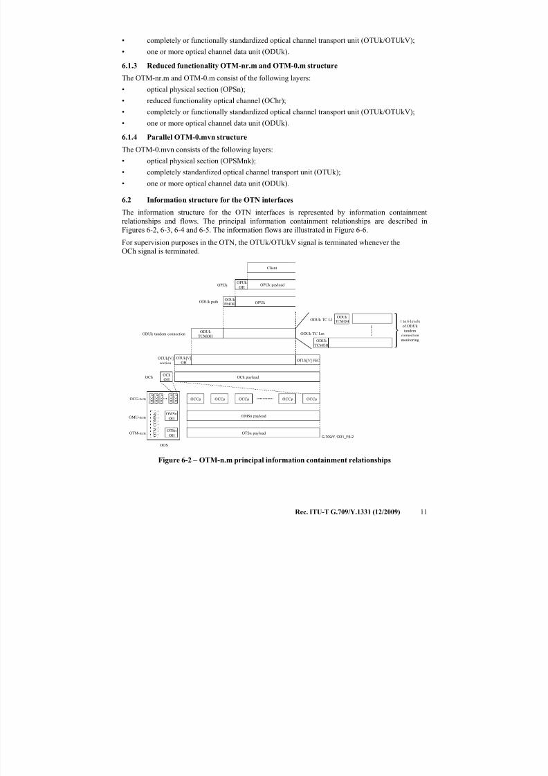
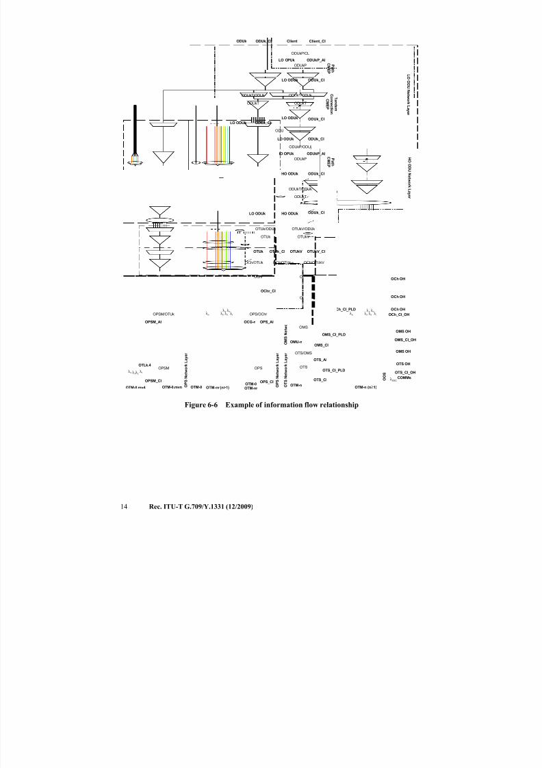
6.2 Information structure for the OTN interfaces
The information structure for the OTN interfaces is represented by information containment
relationships and flows. The principal information containment relationships are described in
Figures 6-2, 6-3, 6-4 and 6-5. The information flows are illustrated in Figure 6-6.
For supervision purposes in the OTN, the OTUk/OTUkV signal is terminated whenever the
OCh signal is terminated.
G.709/Y.1331_F6-2
OPUk payload
Client
ODUk tandem connection
OMSn payload
OTSn payload
OCh payload
1 to 6 levels
of ODUk
tandem
connection
monitoring
OTUk[V]
section
ODUk path
OTUk[V] FEC
OPUk
OCG-n.m
OMU-n.m
OTM-n.m
OCCp
ODUk TC L1
ODUk TC Lm
OCh
OOS
OPUk
OCCpOCCpOCCpOCCp O C C o
O T M C
O M M s
OPUk OH
ODUk PMOH
ODUk
TCMOH
ODUk TCMOH
ODUk
TCMOH
OTUk[V]
OH
OChOH
O C C o
O C C o
O C C o
O C C o
OMSn
OH
OTSn
OH
Figure 6-2 – OTM-n.m principal information containment relationships
7/16/2019 G-709 ITU_T
http://slidepdf.com/reader/full/g-709-itut 20/218
12 Rec. ITU-T G.709/Y.1331 (12/2009)
G.709/Y.1331_F6-3
OPUk payload
Client
ODUk tandem connection
1 to 6 levelsof ODUk
tandemconnection
monitoring
OTUk [V]
section
OCh payload
ODUk path
OTUk[V] FEC
OPUk
ODUk TC L1
ODUk TC Lm
OChr
OPUk
OPUk
OH
ODUk PMOH
ODUk
TCMOH
ODUk TCMOH
ODUk
TCMOH
OTUk[V]
OH
OTM-0.m OPS0
Figure 6-3 – OTM-0.m principal information containment relationships
G.709/Y.1331_F6-4
OPUk payload
Client
ODUk tandem connection
1 to 6 levels
of ODUk
tandem
connectionmonitoring
OTUk [V]
section
OCh payload
ODUk path
OTUk[V] FEC
OPUk
ODUk TC L1
ODUk TC Lm
OChr
OPUk
OPUk
OH
ODUk
PMOH
ODUk
TCMOH
ODUk TCMOH
ODUk
TCMOH
OTUk[V]
OH
OTM-nr.m OPSn
OCG-nr.m OCCp OCCp OCCp OCCp OCCp
Figure 6-4 – OTM-nr.m principal information containment relationships
7/16/2019 G-709 ITU_T
http://slidepdf.com/reader/full/g-709-itut 21/218
Rec. ITU-T G.709/Y.1331 (12/2009) 13
OPUk Payload
Client
ODUkTCMOH
OTUkOH
OTUk FEC
ODUk TandemConnection
OTUkSection
OPUk
OTLCG
OPSMnkOTM-0.mvn
OTLCp
OPUkOH
ODUkPMOH
ODUkTCMOH
ODUkTCMOH
ODUk Path
ODUk TC L1
ODUk TC Lm
1 to 6 levelsof ODUkTandem
ConnectionMonitoring
OPUk
OTLk.n #0 OTLk.n #2 OTLk.n #n-1
OTLCpOTLCp
OTLanes
Figure 6-5 – OTM-0.mvn principal information containment relationships
7/16/2019 G-709 ITU_T
http://slidepdf.com/reader/full/g-709-itut 22/218
14 Rec. ITU-T G.709/Y.1331 (12/2009)
OCh
OTM-n
OMS
OMS/OCh
ODUkT
ODUkT/ODUk
ODUkP
ODUkP/ODUj
OCh
OTS
OTS/OMS
OMU-n
HO ODUk
HO ODUk
HO OPUk
OCG-n
O M S N e t w o r k L a y e r
O T S N e t w o r k L a y e r
O C h N e
t w o r k L a y e r
OMS_CI_PLD
OMS_CI
OTS_CI_PLD
OTS_CI
OMS_AI
OTS_AI
OCh_CI
OCh_CI
ODUkP_AIP a t h
C ME P
T an d em
C onn e c t i on
C ME P
O p t i c al
S e c t i on
C ME P
OTM-n (n≥1)
λ 2λ 1λ n λ 3
λ 4λ 5
λ OSC
OMS_CI_OH
OTS_CI_OH
OCh_CI_OH
O O S
OTS OH
OMS OH
OCh OH
OCh OH
OCh OHOCh_CI_PLD
OMS OH
COMMs
OPS
OTM-0OTM-nr
OCG-n
O P S N e t w o r k L a y e r
OPS_AI
OPS_CI
OTM-nr (n>1)
λ 2λ 1λ n λ 3
λ 4λ 5
OChr
OPS/OChr
OChr_CI
OTM-0
OTUk
OTUk/ODUk
OCh/OTUk
OTUk
OTUkV
OTUkV/ODUk
OCh/OTUk-v
OTUkV
OPSM
OTM-0.mvn O P S N e t w o r k L a y e r
OPSM_AI
OPSM_CI
OTM-0.mv4
OPSM/OTUk
λ 2 λ 1λ 3λ 4
ODUk_CI
ODUk_CI
OTUk_CI OTUkV_CI
Client_CI
ODUkT
ODUkT/ODUk
ODUkP
ODUkP/CL
LO ODUk
LO ODUk
LO OPUk ODUkP_AI
Client
P a t h
C ME P
T an d em
C onn e c t i on
C ME P
ODUk_CI
ODUk_CI
ODU
LO ODUk
LO ODUk ODUk_CI
L O OD UN e t w or k L a y er
H O
OD UN e t w o
r k L a y er
OTLk.4
ODUkT
ODUkT/ODUk
ODUk ODUk_CI
LO ODUk ODUk_CI
OCh/OTUkV
Figure 6-6 − Example of information flow relationship
7/16/2019 G-709 ITU_T
http://slidepdf.com/reader/full/g-709-itut 23/218
Rec. ITU-T G.709/Y.1331 (12/2009) 15
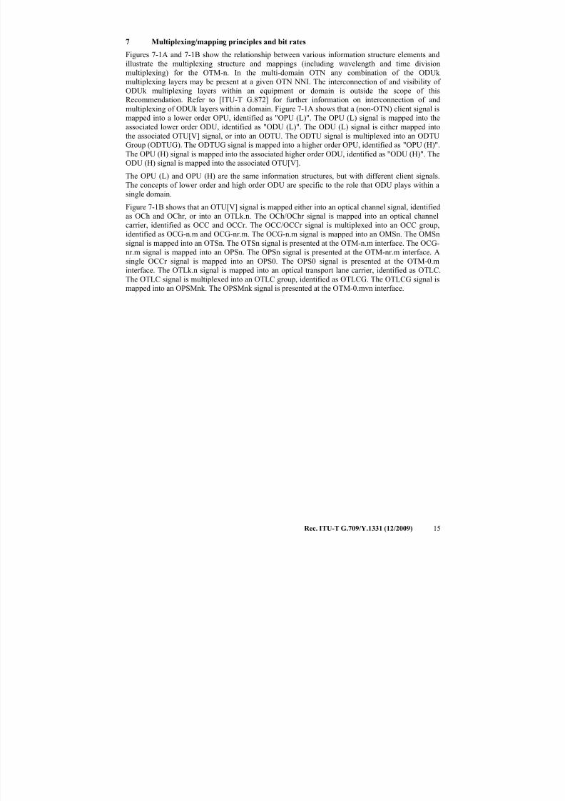
7 Multiplexing/mapping principles and bit rates
Figures 7-1A and 7-1B show the relationship between various information structure elements and
illustrate the multiplexing structure and mappings (including wavelength and time division
multiplexing) for the OTM-n. In the multi-domain OTN any combination of the ODUk
multiplexing layers may be present at a given OTN NNI. The interconnection of and visibility of
ODUk multiplexing layers within an equipment or domain is outside the scope of this
Recommendation. Refer to [ITU-T G.872] for further information on interconnection of andmultiplexing of ODUk layers within a domain. Figure 7-1A shows that a (non-OTN) client signal is
mapped into a lower order OPU, identified as "OPU (L)". The OPU (L) signal is mapped into the
associated lower order ODU, identified as "ODU (L)". The ODU (L) signal is either mapped into
the associated OTU[V] signal, or into an ODTU. The ODTU signal is multiplexed into an ODTU
Group (ODTUG). The ODTUG signal is mapped into a higher order OPU, identified as "OPU (H)".
The OPU (H) signal is mapped into the associated higher order ODU, identified as "ODU (H)". The
ODU (H) signal is mapped into the associated OTU[V].
The OPU (L) and OPU (H) are the same information structures, but with different client signals.
The concepts of lower order and high order ODU are specific to the role that ODU plays within a
single domain.
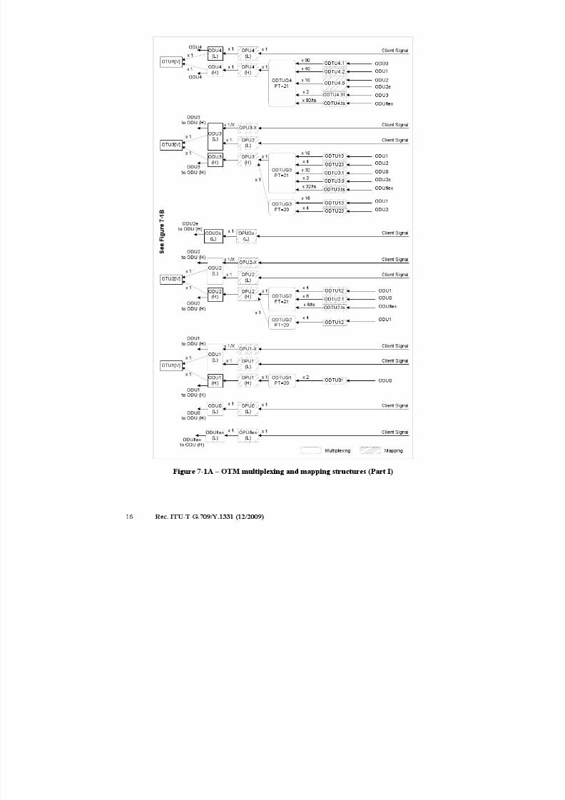
Figure 7-1B shows that an OTU[V] signal is mapped either into an optical channel signal, identified
as OCh and OChr, or into an OTLk.n. The OCh/OChr signal is mapped into an optical channel
carrier, identified as OCC and OCCr. The OCC/OCCr signal is multiplexed into an OCC group,
identified as OCG-n.m and OCG-nr.m. The OCG-n.m signal is mapped into an OMSn. The OMSn
signal is mapped into an OTSn. The OTSn signal is presented at the OTM-n.m interface. The OCG-
nr.m signal is mapped into an OPSn. The OPSn signal is presented at the OTM-nr.m interface. A
single OCCr signal is mapped into an OPS0. The OPS0 signal is presented at the OTM-0.m
interface. The OTLk.n signal is mapped into an optical transport lane carrier, identified as OTLC.
The OTLC signal is multiplexed into an OTLC group, identified as OTLCG. The OTLCG signal is
mapped into an OPSMnk. The OPSMnk signal is presented at the OTM-0.mvn interface.
7/16/2019 G-709 ITU_T
http://slidepdf.com/reader/full/g-709-itut 24/218
7/16/2019 G-709 ITU_T
http://slidepdf.com/reader/full/g-709-itut 25/218
Rec. ITU-T G.709/Y.1331 (12/2009) 17
OTU1[V]
OTU2[V]
OTM-n.m
x k
x j
MappingMultiplexing
OCG-n.m
OCC
OCCx 1
x 1
1 ≤ i+j+k+l ≤ n
OCh
OChx 1
x 1
OTM-nr.m
x k
x jOCG-nr.m
OCCr
OCCr x 1
x 1
1 ≤ i+j+k+l ≤ nOChr
OChr x 1
x 1
OSCx 1
OTM Overhead Signal (OOS)
OTS OH
x 1
x 1
x 1
OTM-0.m
x i
OCCr x 1
OChr x 1
x i
OCCx 1
OChx 1
OMSnOTSn
OPSn
OPS0x 1
OMS OH
OCh OH
COMMS OH
OTU3[V]
OTU4[V]
OCCx 1
OChx 1
OCCr x 1
OChr x 1
x l
x l
S e e F i g u r e 7 - 1 / A
OTM-0.mvn OPSMn4
OTLCx 1
OTLCx 1 x 1
OTL3.n
OTL4.nOTLCG
OTLCGx 1
x n
x n
x 1/n
x 1/nOPSMn3
Figure 7-1B – OTM multiplexing and mapping structures (Part II)
The OTS, OMS, OCh and COMMS overhead is inserted into the OOS using mapping and
multiplexing techniques outside the scope of this Recommendation.
7.1 Mapping
The client signal or an optical channel data tributary unit group (ODTUGk) is mapped into the
OPUk. The OPUk is mapped into an ODUk and the ODUk is mapped into an OTUk[V]. The
OTUk[V] is mapped into an OCh[r] and the OCh[r] is then modulated onto an OCC[r]. The OTUk
may also be mapped into n OTLk.n and an OTLk.n is then modulated onto an OTLC.
7/16/2019 G-709 ITU_T
http://slidepdf.com/reader/full/g-709-itut 26/218
18 Rec. ITU-T G.709/Y.1331 (12/2009)
7.2 Wavelength division multiplex
Up to n (n ≥ 1) OCC[r] are multiplexed into an OCG-n[r].m using wavelength division
multiplexing. The OCC[r] tributary slots of the OCG-n[r].m can be of different size.
The OCG-n[r].m is transported via the OTM-n[r].m. For the case of the full functionality OTM-n.m
interfaces the OSC is multiplexed into the OTM-n.m using wavelength division multiplexing.
n OTLC are aggregated into an OTLCG using wavelength division multiplexing. The OTLCG istransported via the OTM-0.mvn.
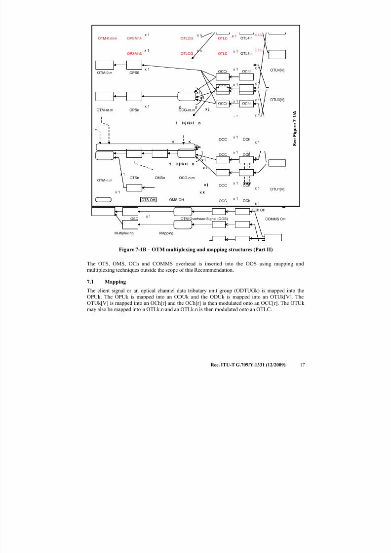
7.3 Bit rates and capacity
The bit rates and tolerance of the OTUk signals are defined in Table 7-1.
The bit rates and tolerance of the ODUk signals are defined in clause 12.2 and Table 7-2.
The bit rates and tolerance of the OPUk and OPUk-Xv payload are defined in Table 7-3.
The OTUk/ODUk/OPUk/OPUk-Xv frame periods are defined in Table 7-4.
The types and bit rates of the OTLk.n signals are defined in Table 7-5.
The 2.5G and 1.25G tributary slot related HO OPUk multiframe periods are defined in Table 7-6.
The ODTU Payload area bandwidths are defined in Table 7-7. The bandwidth depends on the HO
OPUk type (k=1,2,3,4) and the mapping procedure (AMP or GMP). The AMP bandwidths include
the bandwidth provided by the NJO overhead byte. GMP is defined without such NJO byte.
The bit rates and tolerance of the ODUflex(GFP) are defined in Table 7-8.
The number of HO OPUk tributary slots required by LO ODUj are summarized in Table 7-9.
Table 7-1 − OTU types and bit rates
OTU type OTU nominal bit rate OTU bit-rate tolerance
OTU1 255/238 × 2 488 320 kbit/s
±20 ppmOTU2 255/237 × 9 953 280 kbit/s
OTU3 255/236 × 39 813 120 kbit/s
OTU4 255/227 × 99 532 800 kbit/s
NOTE 1 – The nominal OTUk rates are approximately: 2 666 057.143 kbit/s (OTU1),
10 709 225.316 kbit/s (OTU2), 43 018 413.559 kbit/s (OTU3) and 111 809 973.568 kbit/s (OTU4).
NOTE 2 – OTU0, OTU2e and OTUflex are not specified in this Recommendation. ODU0 signals are to be
transported over ODU1, ODU2, ODU3 or ODU4 signals, ODU2e signals are to be transported over ODU3
and ODU4 signals and ODUflex signals are transported over ODU2, ODU3 and ODU4 signals.
7/16/2019 G-709 ITU_T
http://slidepdf.com/reader/full/g-709-itut 27/218
Rec. ITU-T G.709/Y.1331 (12/2009) 19
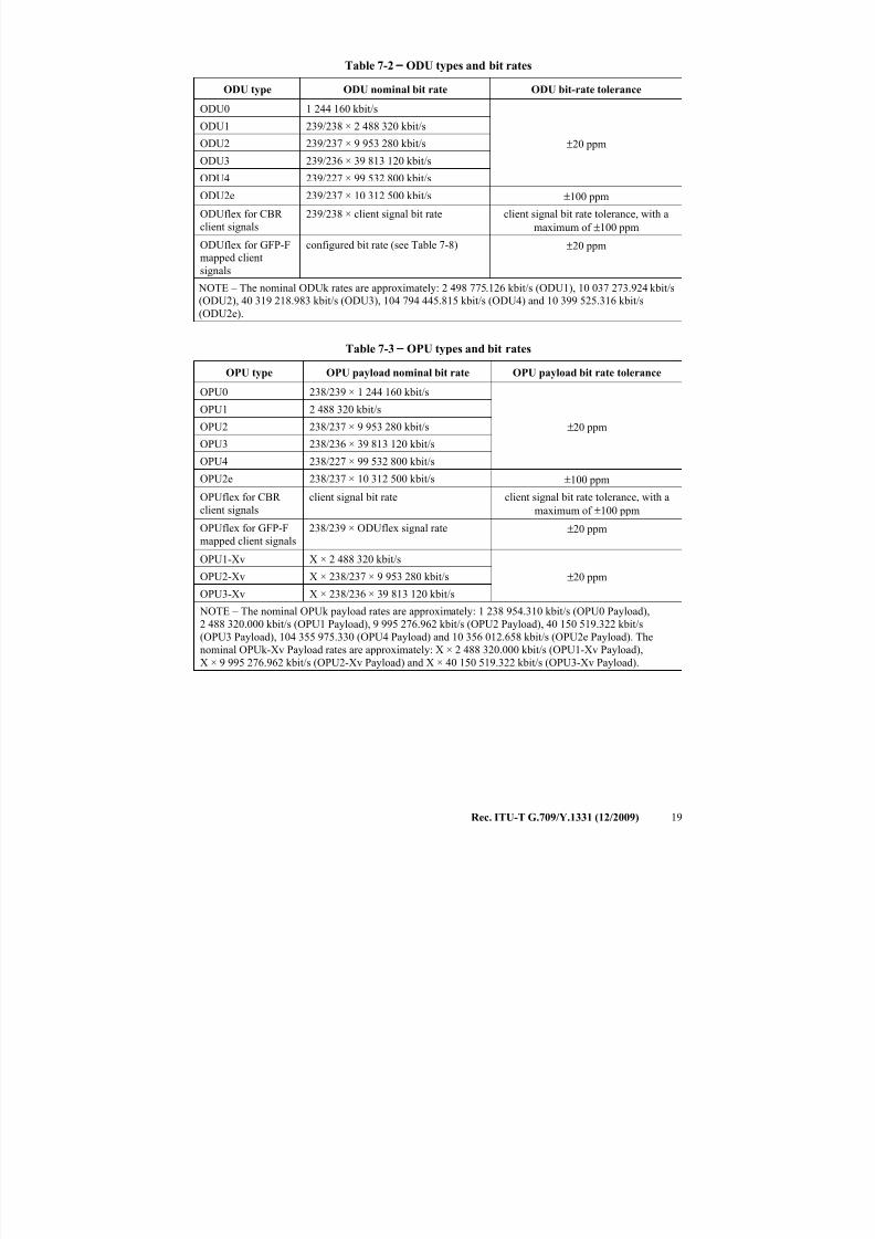
Table 7-2 − ODU types and bit rates
ODU type ODU nominal bit rate ODU bit-rate tolerance
ODU0 1 244 160 kbit/s
±20 ppm
ODU1 239/238 × 2 488 320 kbit/s
ODU2 239/237 × 9 953 280 kbit/s
ODU3 239/236 × 39 813 120 kbit/s
ODU4 239/227 × 99 532 800 kbit/s
ODU2e 239/237 × 10 312 500 kbit/s ±100 ppm
ODUflex for CBR
client signals
239/238 × client signal bit rate client signal bit rate tolerance, with a
maximum of ±100 ppm
ODUflex for GFP-F
mapped client
signals
configured bit rate (see Table 7-8) ±20 ppm
NOTE – The nominal ODUk rates are approximately: 2 498 775.126 kbit/s (ODU1), 10 037 273.924 kbit/s
(ODU2), 40 319 218.983 kbit/s (ODU3), 104 794 445.815 kbit/s (ODU4) and 10 399 525.316 kbit/s(ODU2e).
Table 7-3 − OPU types and bit rates
OPU type OPU payload nominal bit rate OPU payload bit rate tolerance
OPU0 238/239 × 1 244 160 kbit/s
±20 ppm
OPU1 2 488 320 kbit/s
OPU2 238/237 × 9 953 280 kbit/s
OPU3 238/236 × 39 813 120 kbit/s
OPU4 238/227 × 99 532 800 kbit/s
OPU2e 238/237 × 10 312 500 kbit/s ±100 ppm
OPUflex for CBR
client signals
client signal bit rate client signal bit rate tolerance, with a
maximum of ±100 ppm
OPUflex for GFP-F
mapped client signals
238/239 × ODUflex signal rate ±20 ppm
OPU1-Xv X × 2 488 320 kbit/s
±20 ppmOPU2-Xv X × 238/237 × 9 953 280 kbit/s
OPU3-Xv X × 238/236 × 39 813 120 kbit/s
NOTE – The nominal OPUk payload rates are approximately: 1 238 954.310 kbit/s (OPU0 Payload),
2 488 320.000 kbit/s (OPU1 Payload), 9 995 276.962 kbit/s (OPU2 Payload), 40 150 519.322 kbit/s
(OPU3 Payload), 104 355 975.330 (OPU4 Payload) and 10 356 012.658 kbit/s (OPU2e Payload). The
nominal OPUk-Xv Payload rates are approximately: X × 2 488 320.000 kbit/s (OPU1-Xv Payload),
X × 9 995 276.962 kbit/s (OPU2-Xv Payload) and X × 40 150 519.322 kbit/s (OPU3-Xv Payload).
7/16/2019 G-709 ITU_T
http://slidepdf.com/reader/full/g-709-itut 28/218
20 Rec. ITU-T G.709/Y.1331 (12/2009)
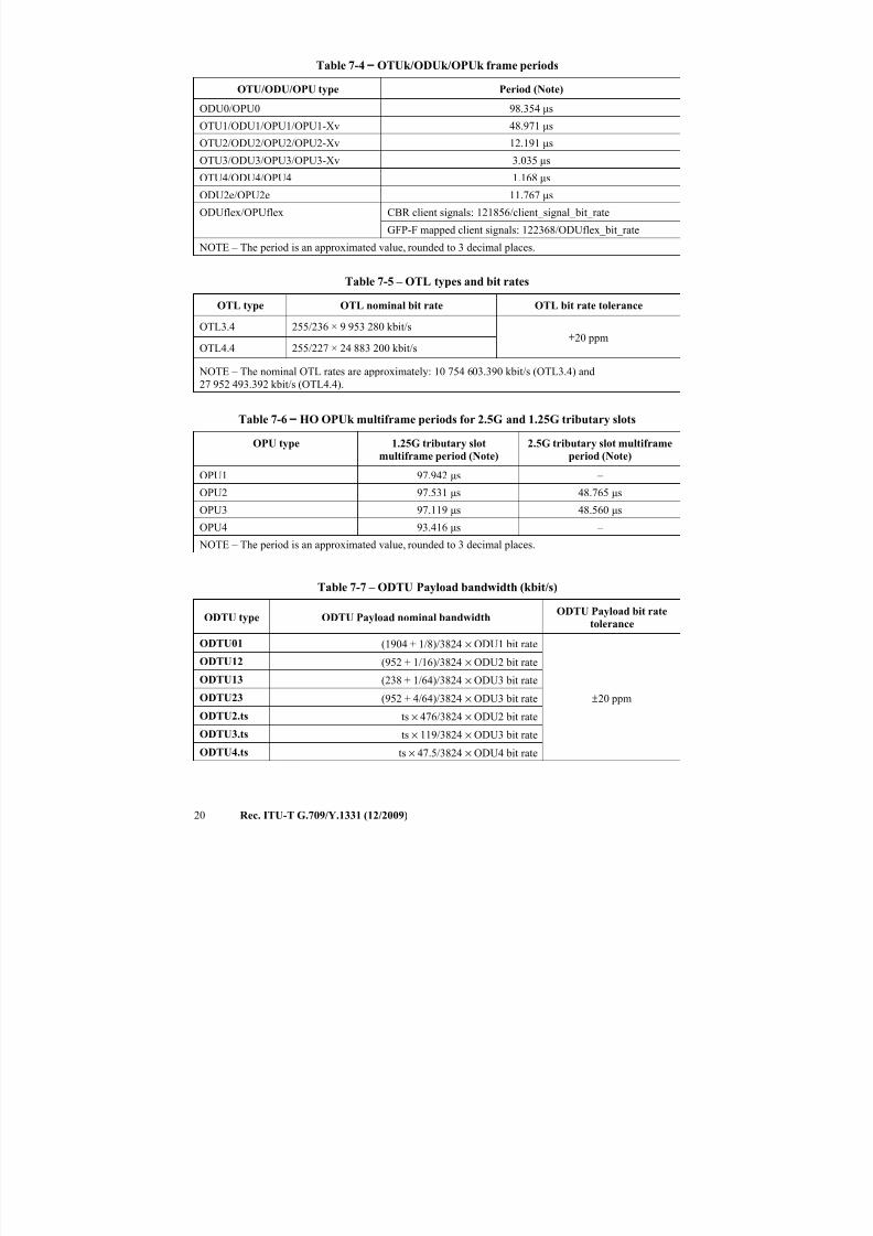
Table 7-4 − OTUk/ODUk/OPUk frame periods
OTU/ODU/OPU type Period (Note)
ODU0/OPU0 98.354 μs
OTU1/ODU1/OPU1/OPU1-Xv 48.971 μs
OTU2/ODU2/OPU2/OPU2-Xv 12.191 μs
OTU3/ODU3/OPU3/OPU3-Xv 3.035 μs
OTU4/ODU4/OPU4 1.168 μs
ODU2e/OPU2e 11.767 μs
ODUflex/OPUflex CBR client signals: 121856/client_signal_bit_rate
GFP-F mapped client signals: 122368/ODUflex_bit_rate
NOTE – The period is an approximated value, rounded to 3 decimal places.
Table 7-5 – OTL types and bit rates
OTL type OTL nominal bit rate OTL bit rate tolerance
OTL3.4 255/236 × 9 953 280 kbit/s±20 ppm
OTL4.4 255/227 × 24 883 200 kbit/s
NOTE – The nominal OTL rates are approximately: 10 754 603.390 kbit/s (OTL3.4) and
27 952 493.392 kbit/s (OTL4.4).
Table 7-6 − HO OPUk multiframe periods for 2.5G and 1.25G tributary slots OPU type 1.25G tributary slot
multiframe period (Note)
2.5G tributary slot multiframe
period (Note)
OPU1 97.942 μs –
OPU2 97.531 μs 48.765 μs
OPU3 97.119 μs 48.560 μs
OPU4 93.416 μs –
NOTE – The period is an approximated value, rounded to 3 decimal places.
Table 7-7 – ODTU Payload bandwidth (kbit/s)
ODTU type ODTU Payload nominal bandwidthODTU Payload bit rate
tolerance
ODTU01 (1904 + 1/8)/3824 × ODU1 bit rate
±20 ppm
ODTU12 (952 + 1/16)/3824 × ODU2 bit rate
ODTU13 (238 + 1/64)/3824 × ODU3 bit rate
ODTU23 (952 + 4/64)/3824 × ODU3 bit rate
ODTU2.ts ts × 476/3824 × ODU2 bit rate
ODTU3.ts ts × 119/3824 × ODU3 bit rate
ODTU4.ts ts × 47.5/3824 × ODU4 bit rate
7/16/2019 G-709 ITU_T
http://slidepdf.com/reader/full/g-709-itut 29/218
Rec. ITU-T G.709/Y.1331 (12/2009) 21
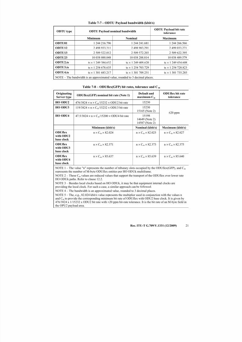
Table 7-7 – ODTU Payload bandwidth (kbit/s)
ODTU type ODTU Payload nominal bandwidthODTU Payload bit rate
tolerance
Minimum Nominal Maximum
ODTU01 1 244 216.796 1 244 241.681 1 244 266.566
ODTU12 2 498 933.311 2 498 983.291 2 499 033.271
ODTU13 2 509 522.012 2 509 572.203 2 509 622.395
ODTU23 10 038 088.048 10 038 288.814 10 038 489.579
ODTU2.ts ts × 1 249 384.632 ts × 1 249 409.620 ts × 1 249 434.608
ODTU3.ts ts × 1 254 678.635 ts × 1 254 703.729 ts × 1 254 728.823
ODTU4.ts ts × 1 301 683.217 ts × 1 301 709.251 ts × 1 301 735.285
NOTE – The bandwidth is an approximated value, rounded to 3 decimal places.
Table 7-8 – ODUflex(GFP) bit rates, tolerance and Cm
Originating
Server typeODUflex(GFP) nominal bit rate (Note 1)
Default and
maximum Cm
ODUflex bit rate
tolerance
HO ODU2 476/3824 × n × Cm/15232 × ODU2 bit rate 15230
±20 ppm
HO ODU3 119/3824 × n × Cm/15232 × ODU3 bit rate 15230
15165 (Note 2)
HO ODU4 47.5/3824 × n × Cm/15200 × ODU4 bit rate 15198
14649 (Note 2)
14587 (Note 2)
Minimum (kbit/s) Nominal (kbit/s) Maximum (kbit/s)
ODUflex
with ODU2
base clock
n × Cm × 82.024 n × Cm × 82.025 n × Cm × 82.027
ODUflex
with ODU3
base clock
n × Cm × 82.371 n × Cm × 82.373 n × Cm × 82.375
ODUflex
with ODU4
base clock
n × Cm × 85.637 n × Cm × 85.639 n × Cm × 85.640
NOTE 1 – The value "n" represents the number of tributary slots occupied by the ODUflex(GFP), and Cm
represents the number of M-byte ODUflex entities per HO ODUk multiframe.
NOTE 2 – These Cm values are reduced values that support the transport of the ODUflex over lower rate
HO ODUk paths. Refer to clause 12.2.
NOTE 3 – Besides local clocks based on HO ODUk, it may be that equipment internal clocks are
providing the local clock. For such a case, a similar approach can be followed.
NOTE 4 – The bandwidth is an approximated value, rounded to 3 decimal places.
NOTE 5 – The, e.g., 82.024 kbit/s value represents the multiplier used in conjunction with the values n
and Cm to provide the corresponding minimum bit rate of ODUflex with ODU2 base clock. It is given by
476/3824 x 1/15232 x ODU2 bit rate with ±20 ppm bit-rate tolerance. It is the bit rate of an M-byte field in
the OPU2 payload area.
7/16/2019 G-709 ITU_T
http://slidepdf.com/reader/full/g-709-itut 30/218
22 Rec. ITU-T G.709/Y.1331 (12/2009)
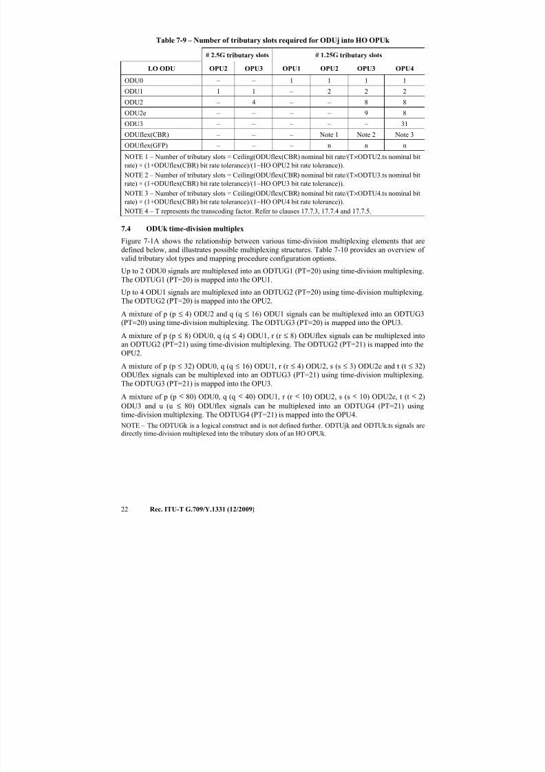
Table 7-9 – Number of tributary slots required for ODUj into HO OPUk
# 2.5G tributary slots # 1.25G tributary slots
LO ODU OPU2 OPU3 OPU1 OPU2 OPU3 OPU4
ODU0 – – 1 1 1 1
ODU1 1 1 – 2 2 2ODU2 – 4 – – 8 8
ODU2e – – – – 9 8
ODU3 – – – – – 31
ODUflex(CBR) – – – Note 1 Note 2 Note 3
ODUflex(GFP) – – – n n n
NOTE 1 – Number of tributary slots = Ceiling(ODUflex(CBR) nominal bit rate/(T×ODTU2.ts nominal bit
rate) × (1+ODUflex(CBR) bit rate tolerance)/(1−HO OPU2 bit rate tolerance)).
NOTE 2 – Number of tributary slots = Ceiling(ODUflex(CBR) nominal bit rate/(T×ODTU3.ts nominal bit
rate) × (1+ODUflex(CBR) bit rate tolerance)/(1−HO OPU3 bit rate tolerance)).
NOTE 3 – Number of tributary slots = Ceiling(ODUflex(CBR) nominal bit rate/(T×ODTU4.ts nominal bit
rate) × (1+ODUflex(CBR) bit rate tolerance)/(1−HO OPU4 bit rate tolerance)).
NOTE 4 – T represents the transcoding factor. Refer to clauses 17.7.3, 17.7.4 and 17.7.5.
7.4 ODUk time-division multiplex
Figure 7-1A shows the relationship between various time-division multiplexing elements that are
defined below, and illustrates possible multiplexing structures. Table 7-10 provides an overview of
valid tributary slot types and mapping procedure configuration options.
Up to 2 ODU0 signals are multiplexed into an ODTUG1 (PT=20) using time-division multiplexing.
The ODTUG1 (PT=20) is mapped into the OPU1.Up to 4 ODU1 signals are multiplexed into an ODTUG2 (PT=20) using time-division multiplexing.
The ODTUG2 (PT=20) is mapped into the OPU2.
A mixture of p (p ≤ 4) ODU2 and q (q ≤ 16) ODU1 signals can be multiplexed into an ODTUG3
(PT=20) using time-division multiplexing. The ODTUG3 (PT=20) is mapped into the OPU3.
A mixture of p (p ≤ 8) ODU0, q (q ≤ 4) ODU1, r (r ≤ 8) ODUflex signals can be multiplexed into
an ODTUG2 (PT=21) using time-division multiplexing. The ODTUG2 (PT=21) is mapped into the
OPU2.
A mixture of p (p ≤ 32) ODU0, q (q ≤ 16) ODU1, r (r ≤ 4) ODU2, s (s ≤ 3) ODU2e and t (t ≤ 32)
ODUflex signals can be multiplexed into an ODTUG3 (PT=21) using time-division multiplexing.The ODTUG3 (PT=21) is mapped into the OPU3.
A mixture of p (p ≤ 80) ODU0, q (q ≤ 40) ODU1, r (r ≤ 10) ODU2, s (s ≤ 10) ODU2e, t (t ≤ 2)
ODU3 and u (u ≤ 80) ODUflex signals can be multiplexed into an ODTUG4 (PT=21) using
time-division multiplexing. The ODTUG4 (PT=21) is mapped into the OPU4.
NOTE – The ODTUGk is a logical construct and is not defined further. ODTUjk and ODTUk.ts signals are
directly time-division multiplexed into the tributary slots of an HO OPUk.
7/16/2019 G-709 ITU_T
http://slidepdf.com/reader/full/g-709-itut 31/218
Rec. ITU-T G.709/Y.1331 (12/2009) 23
Table 7-10 – Overview of ODUj into OPUk mapping types
2.5G tributary slots 1.25G tributary slots
OPU2 OPU3 OPU1 OPU2 OPU3 OPU4
ODU0 – – AMP
(PT=20)
GMP
(PT=21)
GMP
(PT=21)
GMP
(PT=21)
ODU1 AMP
(PT=20)
AMP
(PT=20)
– AMP
(PT=21)
AMP
(PT=21)
GMP
(PT=21)
ODU2 – AMP
(PT=20)
– – AMP
(PT=21)
GMP
(PT=21)
ODU2e – – – – GMP
(PT=21)
GMP
(PT=21)
ODU3 – – – – – GMP
(PT=21)
ODUflex – – – GMP
(PT=21)
GMP
(PT=21)
GMP
(PT=21)
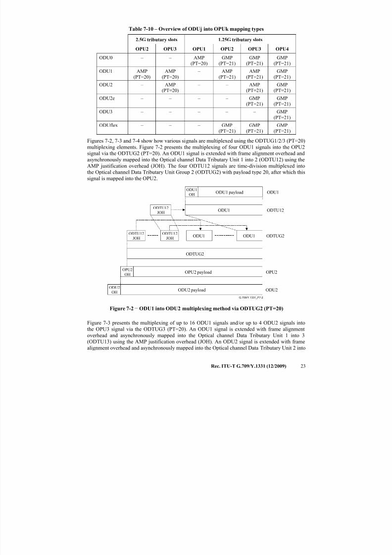
Figures 7-2, 7-3 and 7-4 show how various signals are multiplexed using the ODTUG1/2/3 (PT=20)
multiplexing elements. Figure 7-2 presents the multiplexing of four ODU1 signals into the OPU2
signal via the ODTUG2 (PT=20). An ODU1 signal is extended with frame alignment overhead and
asynchronously mapped into the Optical channel Data Tributary Unit 1 into 2 (ODTU12) using the
AMP justification overhead (JOH). The four ODTU12 signals are time-division multiplexed into
the Optical channel Data Tributary Unit Group 2 (ODTUG2) with payload type 20, after which this
signal is mapped into the OPU2.
G.709/Y.1331_F7-2
ODU1
OHODU1ODU1 payload
ODTU12
JOHODU1 ODTU12
ODU2
OH
OPU2OH
ODU2 payload
OPU2
ODU2
ODTU12
JOHODU1
ODTU12
JOHODU1 ODTUG2
ODTUG2
OPU2 payload
Figure 7-2 − ODU1 into ODU2 multiplexing method via ODTUG2 (PT=20)
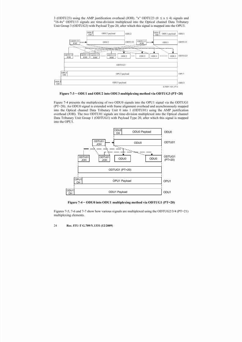
Figure 7-3 presents the multiplexing of up to 16 ODU1 signals and/or up to 4 ODU2 signals into
the OPU3 signal via the ODTUG3 (PT=20). An ODU1 signal is extended with frame alignment
overhead and asynchronously mapped into the Optical channel Data Tributary Unit 1 into 3(ODTU13) using the AMP justification overhead (JOH). An ODU2 signal is extended with frame
alignment overhead and asynchronously mapped into the Optical channel Data Tributary Unit 2 into
7/16/2019 G-709 ITU_T
http://slidepdf.com/reader/full/g-709-itut 32/218
24 Rec. ITU-T G.709/Y.1331 (12/2009)
3 (ODTU23) using the AMP justification overhead (JOH). "x" ODTU23 (0 ≤ x ≤ 4) signals and
"16-4x" ODTU13 signals are time-division multiplexed into the Optical channel Data Tributary
Unit Group 3 (ODTUG3) with Payload Type 20, after which this signal is mapped into the OPU3.
G.709/Y.1331_F7-3
ODU1OH
ODU1ODU1 payload
ODTU13JOH ODU1 ODTU13
ODU3OH
OPU3OH
ODU3 payload
OPU3
ODU3
ODTU23JOH
ODTU23JOH
ODU1 ODTUG3
ODTUG3
OPU3 payload
ODU2OH ODU2ODU2 payload
ODTU23JOH ODU2 ODTU23
ODTU13JOH
ODU2ODTU13
JOHODU2 ODU1
Figure 7-3 − ODU1 and ODU2 into ODU3 multiplexing method via ODTUG3 (PT=20)
Figure 7-4 presents the multiplexing of two ODU0 signals into the OPU1 signal via the ODTUG1
(PT=20). An ODU0 signal is extended with frame alignment overhead and asynchronously mapped
into the Optical channel Data Tributary Unit 0 into 1 (ODTU01) using the AMP justification
overhead (JOH). The two ODTU01 signals are time-division multiplexed into the Optical channel
Data Tributary Unit Group 1 (ODTUG1) with Payload Type 20, after which this signal is mapped
into the OPU1.
ODU0OH ODU0ODU0 Payload
ODTU01JOH
ODU0 ODTU01
ODU1OH
OPU1OH
ODU1 Payload
OPU1
ODU1
ODTU01JOH
ODU0ODTU01
JOHODU0
ODTUG1(PT=20)
ODTUG1 (PT=20)
OPU1 Payload
Figure 7-4 − ODU0 into ODU1 multiplexing method via ODTUG1 (PT=20)
Figures 7-5, 7-6 and 7-7 show how various signals are multiplexed using the ODTUG2/3/4 (PT=21)
multiplexing elements.
7/16/2019 G-709 ITU_T
http://slidepdf.com/reader/full/g-709-itut 33/218
Rec. ITU-T G.709/Y.1331 (12/2009) 25
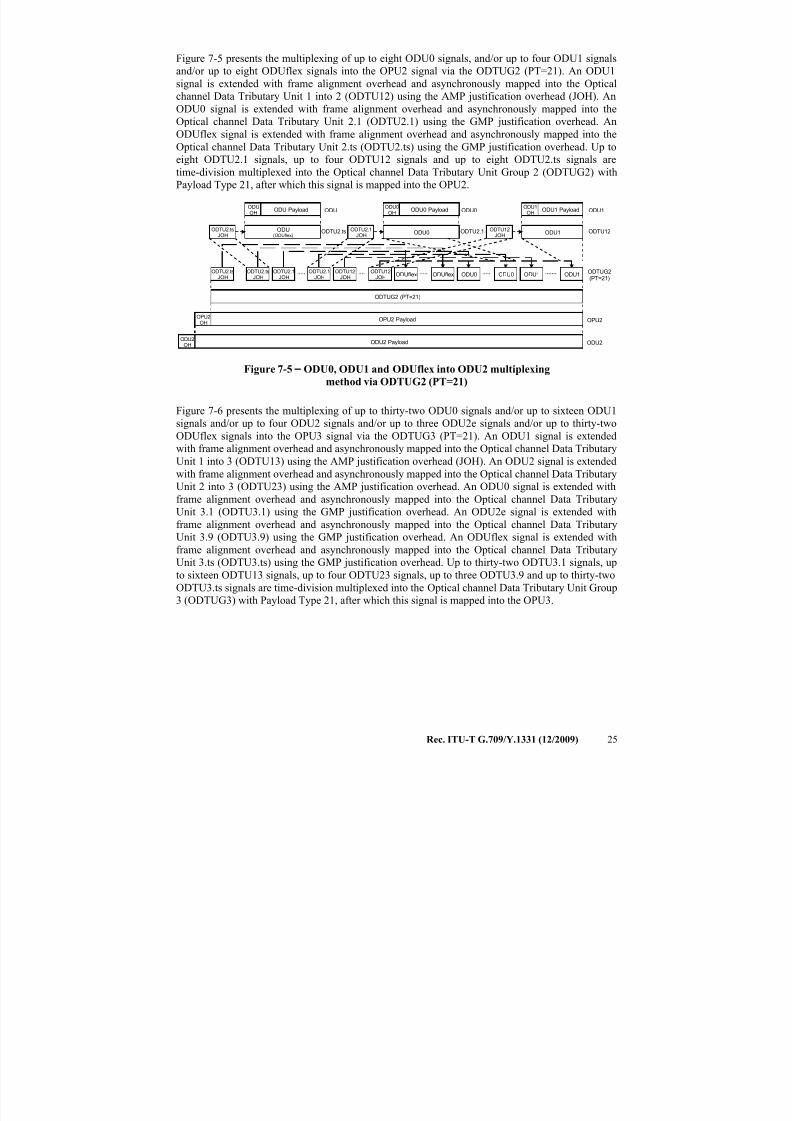
Figure 7-5 presents the multiplexing of up to eight ODU0 signals, and/or up to four ODU1 signals
and/or up to eight ODUflex signals into the OPU2 signal via the ODTUG2 (PT=21). An ODU1
signal is extended with frame alignment overhead and asynchronously mapped into the Optical
channel Data Tributary Unit 1 into 2 (ODTU12) using the AMP justification overhead (JOH). An
ODU0 signal is extended with frame alignment overhead and asynchronously mapped into the
Optical channel Data Tributary Unit 2.1 (ODTU2.1) using the GMP justification overhead. An
ODUflex signal is extended with frame alignment overhead and asynchronously mapped into theOptical channel Data Tributary Unit 2.ts (ODTU2.ts) using the GMP justification overhead. Up to
eight ODTU2.1 signals, up to four ODTU12 signals and up to eight ODTU2.ts signals are
time-division multiplexed into the Optical channel Data Tributary Unit Group 2 (ODTUG2) with
Payload Type 21, after which this signal is mapped into the OPU2.
ODU1OH ODU1ODU1 Payload
ODTU12JOH
ODU1 ODTU12
ODU2OH
OPU2OH
ODU2 Payload
OPU2
ODU2
ODTU12JOH
ODTU12JOH
ODU1 ODTUG2(PT=21)
ODTUG2 (PT=21)
OPU2 Payload
ODU0OH ODU0ODU0 Payload
ODTU2.1JOH
ODU0 ODTU2.1
ODTU2.1JOH
ODU0ODTU2.1JOH
ODU0 ODU1ODTU2.tsJOH
ODTU2.tsJOH
ODUflex ODUflex
ODUOH ODUODU Payload
ODTU2.tsJOH
ODU(ODUflex)
ODTU2.ts
Figure 7-5 − ODU0, ODU1 and ODUflex into ODU2 multiplexing
method via ODTUG2 (PT=21)
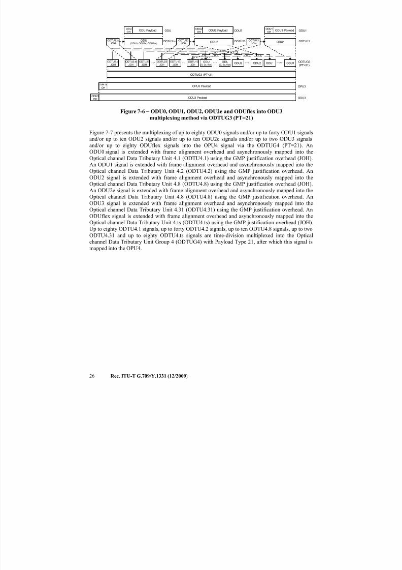
Figure 7-6 presents the multiplexing of up to thirty-two ODU0 signals and/or up to sixteen ODU1signals and/or up to four ODU2 signals and/or up to three ODU2e signals and/or up to thirty-two
ODUflex signals into the OPU3 signal via the ODTUG3 (PT=21). An ODU1 signal is extended
with frame alignment overhead and asynchronously mapped into the Optical channel Data Tributary
Unit 1 into 3 (ODTU13) using the AMP justification overhead (JOH). An ODU2 signal is extended
with frame alignment overhead and asynchronously mapped into the Optical channel Data Tributary
Unit 2 into 3 (ODTU23) using the AMP justification overhead. An ODU0 signal is extended with
frame alignment overhead and asynchronously mapped into the Optical channel Data Tributary
Unit 3.1 (ODTU3.1) using the GMP justification overhead. An ODU2e signal is extended with
frame alignment overhead and asynchronously mapped into the Optical channel Data Tributary
Unit 3.9 (ODTU3.9) using the GMP justification overhead. An ODUflex signal is extended with
frame alignment overhead and asynchronously mapped into the Optical channel Data Tributary
Unit 3.ts (ODTU3.ts) using the GMP justification overhead. Up to thirty-two ODTU3.1 signals, up
to sixteen ODTU13 signals, up to four ODTU23 signals, up to three ODTU3.9 and up to thirty-two
ODTU3.ts signals are time-division multiplexed into the Optical channel Data Tributary Unit Group
3 (ODTUG3) with Payload Type 21, after which this signal is mapped into the OPU3.
7/16/2019 G-709 ITU_T
http://slidepdf.com/reader/full/g-709-itut 34/218
26 Rec. ITU-T G.709/Y.1331 (12/2009)
ODU1OH ODU1ODU1 Payload
ODTU13JOH
ODU1 ODTU13
ODU3OH
OPU3OH
ODU3 Payload
OPU3
ODU3
ODTU13JOH
ODTU13JOH
ODU1 ODTUG3(PT=21)
ODTUG3 (PT=21)
OPU3 Payload
ODU2OH ODU2ODU2 Payload
ODTU23JOH
ODU2 ODTU23
ODTU23JOH
ODU2ODTU23
JOHODU2 ODU1
ODTU3.tsJOH
ODTU3.tsJOH
ODU(0, 2e, flex)
ODU(0, 2e, flex)
ODUOH ODUODU Payload
ODTU3.tsJOH
ODU(ODU0, ODU2e, ODUflex)
ODTU3.ts
Figure 7-6 − ODU0, ODU1, ODU2, ODU2e and ODUflex into ODU3
multiplexing method via ODTUG3 (PT=21)
Figure 7-7 presents the multiplexing of up to eighty ODU0 signals and/or up to forty ODU1 signals
and/or up to ten ODU2 signals and/or up to ten ODU2e signals and/or up to two ODU3 signalsand/or up to eighty ODUflex signals into the OPU4 signal via the ODTUG4 (PT=21). An
ODU0 signal is extended with frame alignment overhead and asynchronously mapped into the
Optical channel Data Tributary Unit 4.1 (ODTU4.1) using the GMP justification overhead (JOH).
An ODU1 signal is extended with frame alignment overhead and asynchronously mapped into the
Optical channel Data Tributary Unit 4.2 (ODTU4.2) using the GMP justification overhead. An
ODU2 signal is extended with frame alignment overhead and asynchronously mapped into the
Optical channel Data Tributary Unit 4.8 (ODTU4.8) using the GMP justification overhead (JOH).
An ODU2e signal is extended with frame alignment overhead and asynchronously mapped into the
Optical channel Data Tributary Unit 4.8 (ODTU4.8) using the GMP justification overhead. An
ODU3 signal is extended with frame alignment overhead and asynchronously mapped into the
Optical channel Data Tributary Unit 4.31 (ODTU4.31) using the GMP justification overhead. An
ODUflex signal is extended with frame alignment overhead and asynchronously mapped into the
Optical channel Data Tributary Unit 4.ts (ODTU4.ts) using the GMP justification overhead (JOH).
Up to eighty ODTU4.1 signals, up to forty ODTU4.2 signals, up to ten ODTU4.8 signals, up to two
ODTU4.31 and up to eighty ODTU4.ts signals are time-division multiplexed into the Optical
channel Data Tributary Unit Group 4 (ODTUG4) with Payload Type 21, after which this signal is
mapped into the OPU4.
7/16/2019 G-709 ITU_T
http://slidepdf.com/reader/full/g-709-itut 35/218
Rec. ITU-T G.709/Y.1331 (12/2009) 27
ODU
OH ODUODU Payload
ODTU4.tsJOH
ODU(0, 1, 2, 2e, 3, 4, flex)
ODTU4.ts
ODU4
OH
OPU4
OH
ODU4 Payload
OPU4
ODU4
ODTU4.tsJOH
ODUODTU4.ts
JOHODU
ODTUG4(PT=21)
ODTUG4 (PT=21)
OPU4 Payload
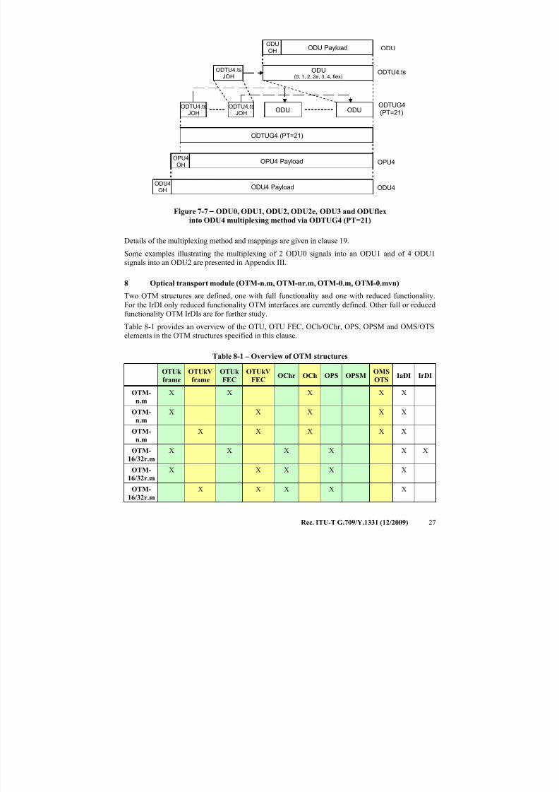
Figure 7-7 − ODU0, ODU1, ODU2, ODU2e, ODU3 and ODUflex
into ODU4 multiplexing method via ODTUG4 (PT=21)
Details of the multiplexing method and mappings are given in clause 19.
Some examples illustrating the multiplexing of 2 ODU0 signals into an ODU1 and of 4 ODU1
signals into an ODU2 are presented in Appendix III.
8 Optical transport module (OTM-n.m, OTM-nr.m, OTM-0.m, OTM-0.mvn)
Two OTM structures are defined, one with full functionality and one with reduced functionality.
For the IrDI only reduced functionality OTM interfaces are currently defined. Other full or reduced
functionality OTM IrDIs are for further study.
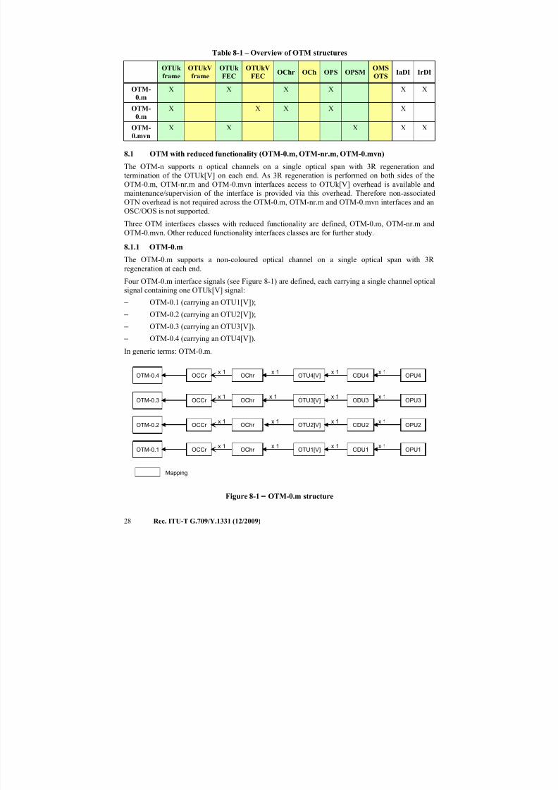
Table 8-1 provides an overview of the OTU, OTU FEC, OCh/OChr, OPS, OPSM and OMS/OTS
elements in the OTM structures specified in this clause.
Table 8-1 – Overview of OTM structures
OTUk
frame
OTUkV
frame
OTUk
FEC
OTUkV
FECOChr OCh OPS OPSM
OMS
OTSIaDI IrDI
OTM-
n.m
X X X X X
OTM-
n.m
X X X X X
OTM-
n.m
X X X X X
OTM-
16/32r.m
X X X X X X
OTM-
16/32r.m
X X X X X
OTM-
16/32r.m
X X X X X
7/16/2019 G-709 ITU_T
http://slidepdf.com/reader/full/g-709-itut 36/218
28 Rec. ITU-T G.709/Y.1331 (12/2009)
Table 8-1 – Overview of OTM structures
OTUk
frame
OTUkV
frame
OTUk
FEC
OTUkV
FECOChr OCh OPS OPSM
OMS
OTSIaDI IrDI
OTM-
0.m
X X X X X X
OTM-
0.m
X X X X X
OTM-
0.mvn
X X X X X
8.1 OTM with reduced functionality (OTM-0.m, OTM-nr.m, OTM-0.mvn)
The OTM-n supports n optical channels on a single optical span with 3R regeneration and
termination of the OTUk[V] on each end. As 3R regeneration is performed on both sides of the
OTM-0.m, OTM-nr.m and OTM-0.mvn interfaces access to OTUk[V] overhead is available and
maintenance/supervision of the interface is provided via this overhead. Therefore non-associatedOTN overhead is not required across the OTM-0.m, OTM-nr.m and OTM-0.mvn interfaces and an
OSC/OOS is not supported.
Three OTM interfaces classes with reduced functionality are defined, OTM-0.m, OTM-nr.m and
OTM-0.mvn. Other reduced functionality interfaces classes are for further study.
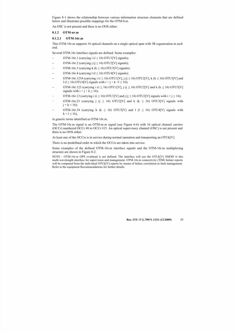
8.1.1 OTM-0.m
The OTM-0.m supports a non-coloured optical channel on a single optical span with 3R
regeneration at each end.
Four OTM-0.m interface signals (see Figure 8-1) are defined, each carrying a single channel optical
signal containing one OTUk[V] signal:
− OTM-0.1 (carrying an OTU1[V]);
− OTM-0.2 (carrying an OTU2[V]);
− OTM-0.3 (carrying an OTU3[V]).
− OTM-0.4 (carrying an OTU4[V]).
In generic terms: OTM-0.m.
ODU1 OPU1
ODU2 OPU2x 1
ODU3
x 1
OPU3x 1
OTU1[V]
OTU2]V]
OTU3[V]x 1
x 1
x 1
Mapping
OCCr
OCCr
OCCr x 1
x 1
x 1OChr
OChr
OChr x 1
x 1
x 1
OTM-0.3
OTM-0.2
OTM-0.1
ODU4 OPU4x 1
OTU4[V]x 1
OCCr x 1
OChr x 1
OTM-0.4
Figure 8-1 − OTM-0.m structure
7/16/2019 G-709 ITU_T
http://slidepdf.com/reader/full/g-709-itut 37/218
Rec. ITU-T G.709/Y.1331 (12/2009) 29
Figure 8-1 shows the relationship between various information structure elements that are defined
below and illustrates possible mappings for the OTM-0.m.
An OSC is not present and there is no OOS either.
8.1.2 OTM-nr.m
8.1.2.1 OTM-16r.m
This OTM-16r.m supports 16 optical channels on a single optical span with 3R regeneration at each
end.
Several OTM-16r interface signals are defined. Some examples:
− OTM-16r.1 (carrying i (i ≤ 16) OTU1[V] signals);
− OTM-16r.2 (carrying j (j ≤ 16) OTU2[V] signals);
− OTM-16r.3 (carrying k (k ≤ 16) OTU3[V] signals);
− OTM-16r.4 (carrying l (l ≤ 16) OTU4[V] signals);
− OTM-16r.1234 (carrying i (i ≤ 16) OTU1[V], j (j ≤ 16) OTU2[V], k (k ≤ 16) OTU3[V] and
l (l ≤ 16) OTU4[V] signals with i + j + k +l ≤ 16);
− OTM-16r.123 (carrying i (i ≤ 16) OTU1[V], j (j ≤ 16) OTU2[V] and k (k ≤ 16) OTU3[V]
signals with i + j + k ≤ 16);
− OTM-16r.12 (carrying i (i ≤ 16) OTU1[V] and j (j ≤ 16) OTU2[V] signals with i + j ≤ 16);
− OTM-16r.23 (carrying j (j ≤ 16) OTU2[V] and k (k ≤ 16) OTU3[V] signals with
j + k ≤ 16);
− OTM-16r.34 (carrying k (k ≤ 16) OTU3[V] and l (l ≤ 16) OTU4[V] signals with
k + l ≤ 16),
in generic terms identified as OTM-16r.m.
The OTM-16r.m signal is an OTM-nr.m signal (see Figure 6-6) with 16 optical channel carriers
(OCCr) numbered OCCr #0 to OCCr #15. An optical supervisory channel (OSC) is not present and
there is no OOS either.
At least one of the OCCrs is in service during normal operation and transporting an OTUk[V].
There is no predefined order in which the OCCrs are taken into service.
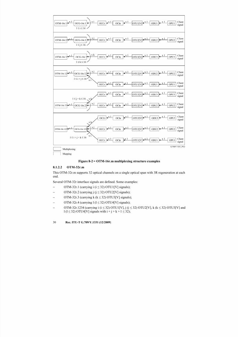
Some examples of the defined OTM-16r.m interface signals and the OTM-16r.m multiplexing
structure are shown in Figure 8-2.
NOTE – OTM-16r.m OPS overhead is not defined. The interface will use the OTUk[V] SMOH in this
multi-wavelength interface for supervision and management. OTM-16r.m connectivity (TIM) failure reports
will be computed from the individual OTUk[V] reports by means of failure correlation in fault management.
Refer to the equipment Recommendations for further details.
7/16/2019 G-709 ITU_T
http://slidepdf.com/reader/full/g-709-itut 38/218
30 Rec. ITU-T G.709/Y.1331 (12/2009)
G.709/Y.1331_F8-2
Mapping
Multiplexing
Clientsignal
Client
signal
Client
signal
Client
signal
Clientsignal
Client
signal
Clientsignal
Clientsignal
Client
signal
Clientsignal
x 1
x 1
x 1
x 1
x 1
x 1
x 1
x 1
x 1
x 1
x 1
x 1
x 1
x 1
x 1
x 1
x 1
x 1
x 1
x 1
x 1
x 1
x 1
x 1
x 1
x 1
x 1
x 1
x 1
x 1
x 1
x 1
x 1
x 1
x 1
x 1
x 1
x 1
x 1
x 1
OPU1
OPU2
OPU3
OPU2
OPU3
OPU1
OPU2
OPU3
OPU2
OPU1
ODU1
ODU2
ODU3
ODU2
ODU3
ODU1
ODU2
ODU3
ODU2
ODU1
OTU1[V]
OTU2[V]
OTU3[V]
OTU2[V]
OTU3[V]
OTU1[V]
OTU2[V]
OTU3[V]
OTU2[V]
OTU1[V]
OCCr
OCCr
OCCr
OChr
OChr
OChr
OCCr
OCCr
OChr
OChr
OCCr
OCCr
OChr
OChr
OCCr OChr
OChr
OCCr OChr
OTM-16r.123
x i
x j
x k
OCG-16r.123x 1
OTM-16r.23x j
x k
OCG-16r.23x 1
OTM-16r.12
x i
x jOCG-16r.12
x 1
OTM-16r.3x k
OCG-16r.3x 1
OTM-16r.2
x j
OCG-16r.2x 1
OTM-16r.1x i
OCG-16r.1x 1
OCCr
1 ≤ i ≤ 16
1 ≤ j ≤ 16
1 ≤ k ≤ 16
1 ≤ i + j ≤ 16
1 ≤ j + k ≤ 16
1 ≤ i + j + k ≤ 16
Figure 8-2 − OTM-16r.m multiplexing structure examples
8.1.2.2 OTM-32r.m
This OTM-32r.m supports 32 optical channels on a single optical span with 3R regeneration at each
end.
Several OTM-32r interface signals are defined. Some examples:
− OTM-32r.1 (carrying i (i ≤ 32) OTU1[V] signals);
− OTM-32r.2 (carrying j (j ≤ 32) OTU2[V] signals);
− OTM-32r.3 (carrying k (k ≤ 32) OTU3[V] signals);
− OTM-32r.4 (carrying l (l ≤ 32) OTU4[V] signals);
− OTM-32r.1234 (carrying i (i ≤ 32) OTU1[V], j (j ≤ 32) OTU2[V], k (k ≤ 32) OTU3[V] and
l (l ≤ 32) OTU4[V] signals with i + j + k + l ≤ 32);
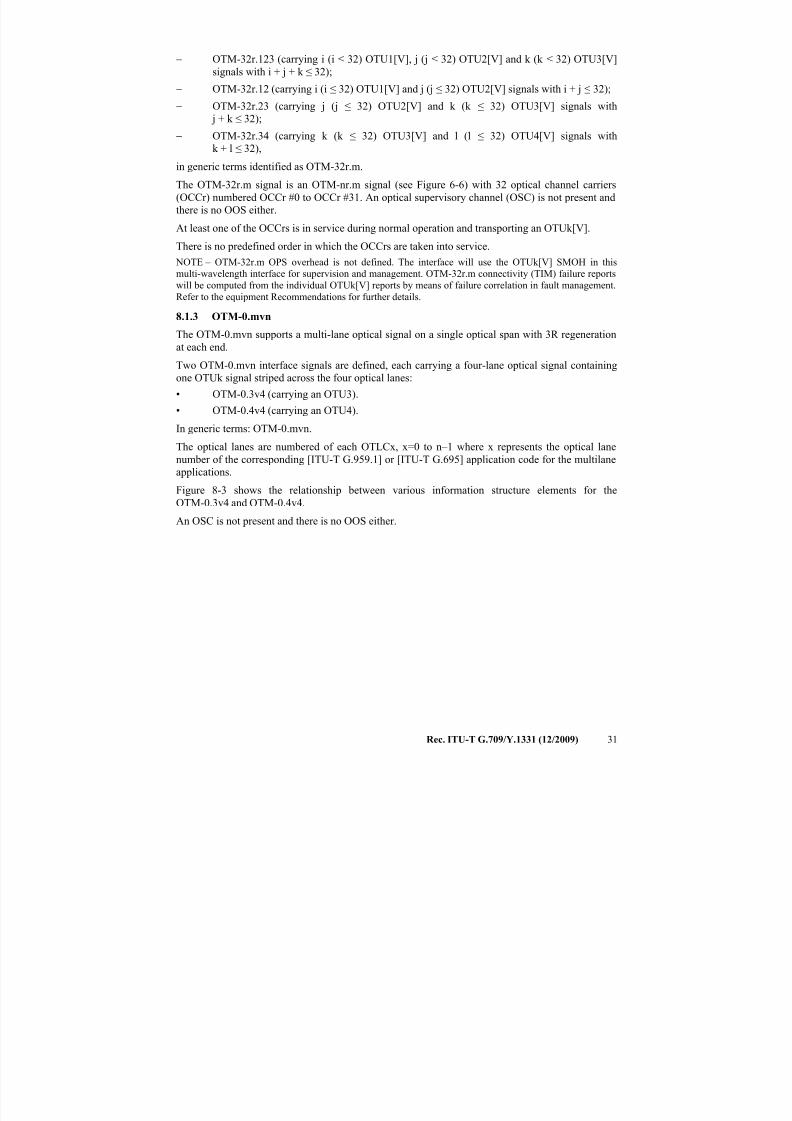
7/16/2019 G-709 ITU_T
http://slidepdf.com/reader/full/g-709-itut 39/218
Rec. ITU-T G.709/Y.1331 (12/2009) 31
− OTM-32r.123 (carrying i (i ≤ 32) OTU1[V], j (j ≤ 32) OTU2[V] and k (k ≤ 32) OTU3[V]
signals with i + j + k ≤ 32);
− OTM-32r.12 (carrying i (i ≤ 32) OTU1[V] and j (j ≤ 32) OTU2[V] signals with i + j ≤ 32);
− OTM-32r.23 (carrying j (j ≤ 32) OTU2[V] and k (k ≤ 32) OTU3[V] signals with
j + k ≤ 32);
− OTM-32r.34 (carrying k (k ≤ 32) OTU3[V] and l (l ≤ 32) OTU4[V] signals withk + l ≤ 32),
in generic terms identified as OTM-32r.m.
The OTM-32r.m signal is an OTM-nr.m signal (see Figure 6-6) with 32 optical channel carriers
(OCCr) numbered OCCr #0 to OCCr #31. An optical supervisory channel (OSC) is not present and
there is no OOS either.
At least one of the OCCrs is in service during normal operation and transporting an OTUk[V].
There is no predefined order in which the OCCrs are taken into service.
NOTE – OTM-32r.m OPS overhead is not defined. The interface will use the OTUk[V] SMOH in this
multi-wavelength interface for supervision and management. OTM-32r.m connectivity (TIM) failure reportswill be computed from the individual OTUk[V] reports by means of failure correlation in fault management.
Refer to the equipment Recommendations for further details.
8.1.3 OTM-0.mvn
The OTM-0.mvn supports a multi-lane optical signal on a single optical span with 3R regeneration
at each end.
Two OTM-0.mvn interface signals are defined, each carrying a four-lane optical signal containing
one OTUk signal striped across the four optical lanes:
• OTM-0.3v4 (carrying an OTU3).
• OTM-0.4v4 (carrying an OTU4).
In generic terms: OTM-0.mvn.
The optical lanes are numbered of each OTLCx, x=0 to n–1 where x represents the optical lane
number of the corresponding [ITU-T G.959.1] or [ITU-T G.695] application code for the multilane
applications.
Figure 8-3 shows the relationship between various information structure elements for the
OTM-0.3v4 and OTM-0.4v4.
An OSC is not present and there is no OOS either.
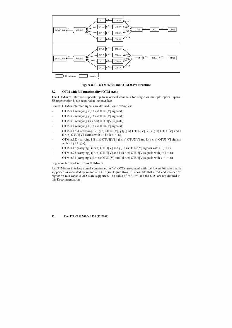
7/16/2019 G-709 ITU_T
http://slidepdf.com/reader/full/g-709-itut 40/218
32 Rec. ITU-T G.709/Y.1331 (12/2009)
ODU4 OPU4x 1
OTU4x 1
MappingMultiplexing
OTM-0.4v4 OTLCG
OTLCx 1
OTL4.4 x 1/4
x 1OTLC
x 1OTL4.4 x 1/4
OTLCx 1
OTL4.4
x 1/4
OTLCx 1
OTL4.4x 1/4
ODU3 OPU3x 1
OTU3x 1
OTM-0.3v4 OTLCG
OTLCx 1
OTL3.4 x 1/4
x 1OTLC
x 1OTL3.4 x 1/4
OTLCx 1
OTL3.4
x 1/4
OTLC
x 1
OTL3.4
x 1/4
Figure 8-3 – OTM-0.3v4 and OTM-0.4v4 structure
8.2 OTM with full functionality (OTM-n.m)
The OTM-n.m interface supports up to n optical channels for single or multiple optical spans.
3R regeneration is not required at the interface.
Several OTM-n interface signals are defined. Some examples:
– OTM-n.1 (carrying i (i ≤ n) OTU1[V] signals);
– OTM-n.2 (carrying j (j ≤ n) OTU2[V] signals);
– OTM-n.3 (carrying k (k ≤ n) OTU3[V] signals);
− OTM-n.4 (carrying l (l ≤ n) OTU4[V] signals);
− OTM-n.1234 (carrying i (i ≤ n) OTU1[V], j (j ≤ n) OTU2[V], k (k ≤ n) OTU3[V] and l
(l ≤ n) OTU4[V] signals with i + j + k +l ≤ n);
– OTM-n.123 (carrying i (i ≤ n) OTU1[V], j (j ≤ n) OTU2[V] and k (k ≤ n) OTU3[V] signals
with i + j + k ≤ n);
– OTM-n.12 (carrying i (i ≤ n) OTU1[V] and j (j ≤ n) OTU2[V] signals with i + j ≤ n);
– OTM-n.23 (carrying j (j ≤ n) OTU2[V] and k (k ≤ n) OTU3[V] signals with j + k ≤ n);
− OTM-n.34 (carrying k (k ≤ n) OTU3[V] and l (l ≤ n) OTU4[V] signals with k + l ≤ n),in generic terms identified as OTM-n.m.
An OTM-n.m interface signal contains up to "n" OCCs associated with the lowest bit rate that is
supported as indicated by m and an OSC (see Figure 8-4). It is possible that a reduced number of
higher bit rate capable OCCs are supported. The value of "n", "m" and the OSC are not defined in
this Recommendation.
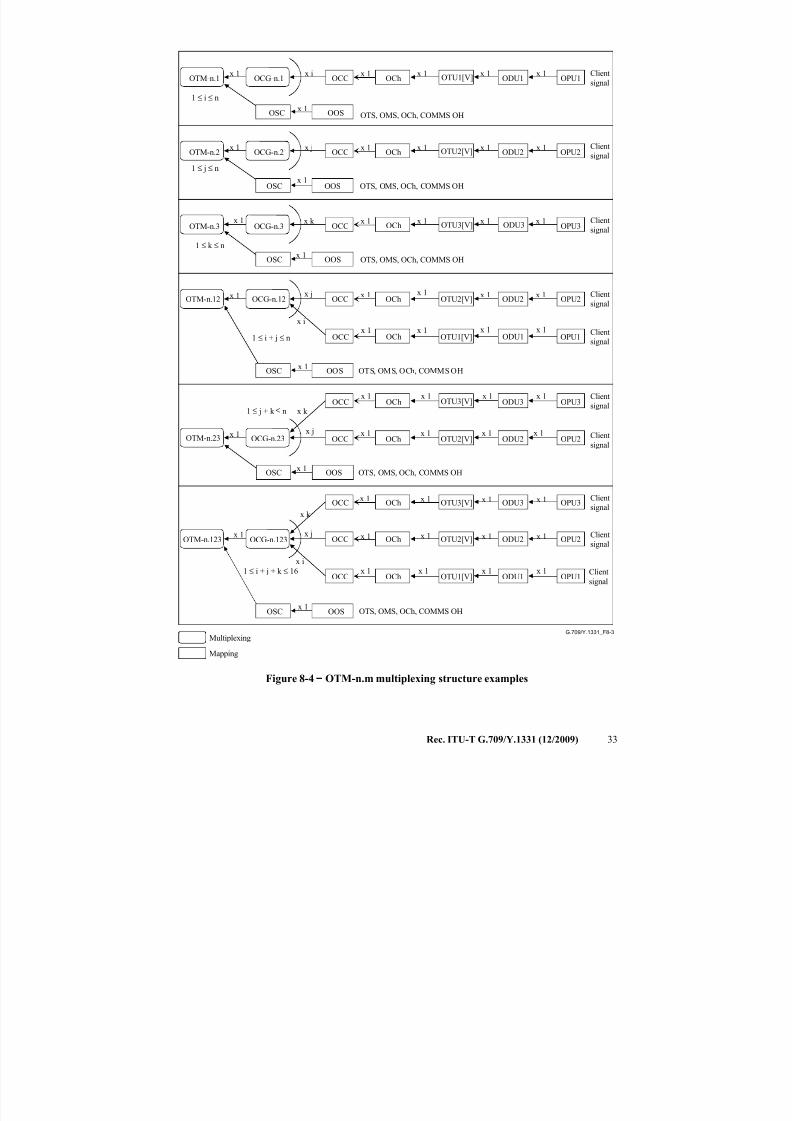
7/16/2019 G-709 ITU_T
http://slidepdf.com/reader/full/g-709-itut 41/218
Rec. ITU-T G.709/Y.1331 (12/2009) 33
G.709/Y.1331_F8-3
Mapping
Multiplexing
Client
signal
Client
signal
Client
signal
Client
signal
Client
signal
Client
signal
Client
signal
Client
signal
Client
signal
Client
signal
OOS OTS, OMS, OCh, COMMS OHx 1
OPU3x 1
OTU3[V]x 1
OCCx 1
OChx 1
OPU2x 1
OTU2[V]x 1x j
OCCx 1
OChx 1
OPU1x 1
OTU1[V]x 1x i
OCCx 1
OChx 1
OOS OTS, OMS, OCh, COMMS OHx 1
ODU2 OPU2x 1
OTU2[V]x 1
OTM-n.12 OCG-n.12 OCCx 1
OChx 1
ODU3x k
ODU2
ODU1
OOS OTS, OMS, OCh, COMMS OHx 1
ODU2 OPU2x 1
ODU3 OPU3x 1
OTU2[V]
OTU3[V]x 1
x 1x j
x k
OCC
OCCx 1
x 1OCh
OChx 1
x 1
OPU1x 1x 1
x i
x j
OCCx 1
OCh
x 1
x 1
OOS OTS, OMS, OCh, COMMS OHx 1
OOS OTS, OMS, OCh, COMMS OHOSCx 1
ODU1 OPU1
ODU2 OPU2x 1
ODU3
x 1
OPU3x 1
OTU1[V]
OTU2[V]
OTU3[V] x 1
x 1
x 1
OTM-n.123
x i
x j
x k
OCG-n.123
OCC
OCC
OCCx 1
x 1
x 1OCh
OCh
OChx 1
x 1
x 1
x 1
ODU1OTU1[V]
OTM-n.3 OCG-n.3x 1
OOSOSCx 1
1 ≤ k ≤ n
1 ≤ i + j + k ≤ 16
OSC
OTM-n.23 OCG-n.23x 1
OTM-n.2 OCG-n.2x 1
OTM-n.1 OCG-n.1x 1
OSC
OSC
OSC
1 ≤ i ≤ n
1 ≤ j ≤ n
1 ≤ i + j ≤ n
1 ≤ j + k ≤ n
OTS, OMS, OCh, COMMS OH
Figure 8-4 − OTM-n.m multiplexing structure examples
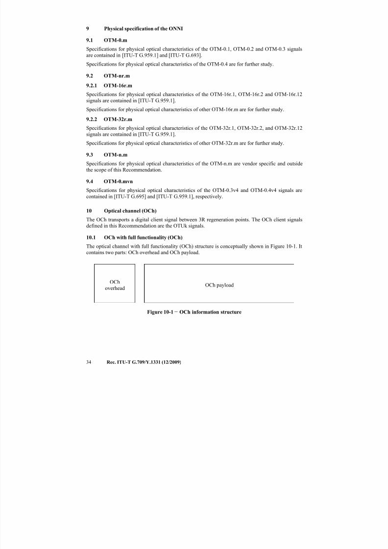
7/16/2019 G-709 ITU_T
http://slidepdf.com/reader/full/g-709-itut 42/218
34 Rec. ITU-T G.709/Y.1331 (12/2009)
9 Physical specification of the ONNI
9.1 OTM-0.m
Specifications for physical optical characteristics of the OTM-0.1, OTM-0.2 and OTM-0.3 signals
are contained in [ITU-T G.959.1] and [ITU-T G.693].
Specifications for physical optical characteristics of the OTM-0.4 are for further study.
9.2 OTM-nr.m
9.2.1 OTM-16r.m
Specifications for physical optical characteristics of the OTM-16r.1, OTM-16r.2 and OTM-16r.12
signals are contained in [ITU-T G.959.1].
Specifications for physical optical characteristics of other OTM-16r.m are for further study.
9.2.2 OTM-32r.m
Specifications for physical optical characteristics of the OTM-32r.1, OTM-32r.2, and OTM-32r.12
signals are contained in [ITU-T G.959.1].
Specifications for physical optical characteristics of other OTM-32r.m are for further study.
9.3 OTM-n.m
Specifications for physical optical characteristics of the OTM-n.m are vendor specific and outside
the scope of this Recommendation.
9.4 OTM-0.mvn
Specifications for physical optical characteristics of the OTM-0.3v4 and OTM-0.4v4 signals are
contained in [ITU-T G.695] and [ITU-T G.959.1], respectively.
10 Optical channel (OCh)
The OCh transports a digital client signal between 3R regeneration points. The OCh client signals
defined in this Recommendation are the OTUk signals.
10.1 OCh with full functionality (OCh)
The optical channel with full functionality (OCh) structure is conceptually shown in Figure 10-1. It
contains two parts: OCh overhead and OCh payload.
OCh
overheadOCh payload
Figure 10-1 − OCh information structure
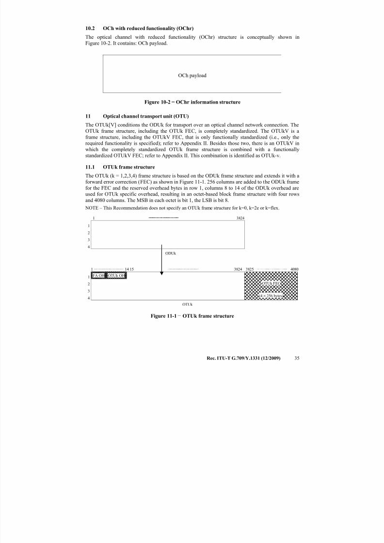
7/16/2019 G-709 ITU_T
http://slidepdf.com/reader/full/g-709-itut 43/218
Rec. ITU-T G.709/Y.1331 (12/2009) 35
10.2 OCh with reduced functionality (OChr)
The optical channel with reduced functionality (OChr) structure is conceptually shown in
Figure 10-2. It contains: OCh payload.
OCh payload
Figure 10-2 − OChr information structure
11 Optical channel transport unit (OTU)
The OTUk[V] conditions the ODUk for transport over an optical channel network connection. The
OTUk frame structure, including the OTUk FEC, is completely standardized. The OTUkV is aframe structure, including the OTUkV FEC, that is only functionally standardized (i.e., only the
required functionality is specified); refer to Appendix II. Besides those two, there is an OTUkV in
which the completely standardized OTUk frame structure is combined with a functionally
standardized OTUkV FEC; refer to Appendix II. This combination is identified as OTUk-v.
11.1 OTUk frame structure
The OTUk (k = 1,2,3,4) frame structure is based on the ODUk frame structure and extends it with a
forward error correction (FEC) as shown in Figure 11-1. 256 columns are added to the ODUk frame
for the FEC and the reserved overhead bytes in row 1, columns 8 to 14 of the ODUk overhead are
used for OTUk specific overhead, resulting in an octet-based block frame structure with four rows
and 4080 columns. The MSB in each octet is bit 1, the LSB is bit 8.
NOTE – This Recommendation does not specify an OTUk frame structure for k=0, k=2e or k=flex.
1
2
3
4
1 3824
ODUk
1
2
3
4
1 3824
OTUk OH
OTUk
3825 4080
FA OH
14 15
(4 × 256 bytes)
OTUk FEC
Figure 11-1 − OTUk frame structure
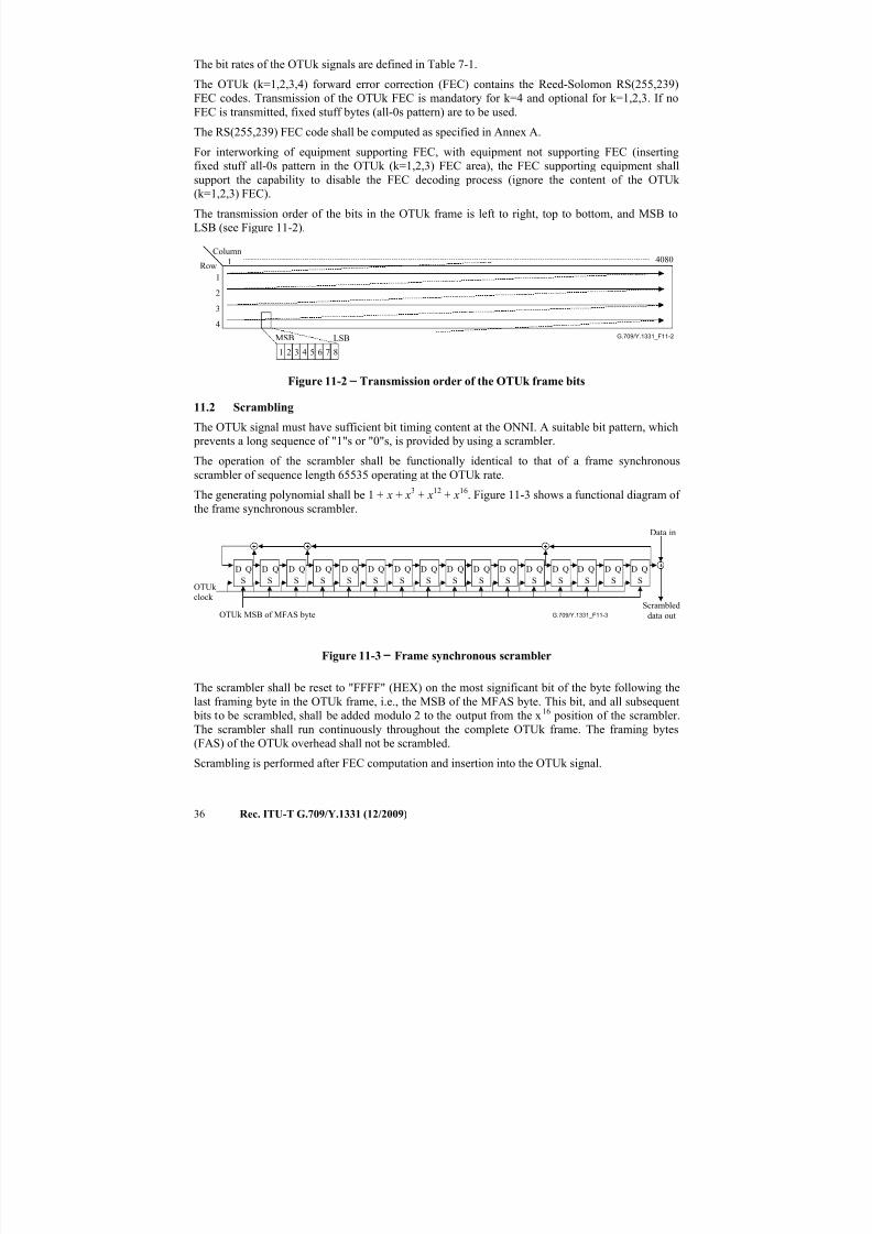
7/16/2019 G-709 ITU_T
http://slidepdf.com/reader/full/g-709-itut 44/218
36 Rec. ITU-T G.709/Y.1331 (12/2009)
The bit rates of the OTUk signals are defined in Table 7-1.
The OTUk (k=1,2,3,4) forward error correction (FEC) contains the Reed-Solomon RS(255,239)
FEC codes. Transmission of the OTUk FEC is mandatory for k=4 and optional for k=1,2,3. If no
FEC is transmitted, fixed stuff bytes (all-0s pattern) are to be used.
The RS(255,239) FEC code shall be computed as specified in Annex A.
For interworking of equipment supporting FEC, with equipment not supporting FEC (insertingfixed stuff all-0s pattern in the OTUk (k=1,2,3) FEC area), the FEC supporting equipment shall
support the capability to disable the FEC decoding process (ignore the content of the OTUk
(k=1,2,3) FEC).
The transmission order of the bits in the OTUk frame is left to right, top to bottom, and MSB to
LSB (see Figure 11-2).
G.709/Y.1331_F11-2
Row
Column
1
2
3
4
1
1 2 3 4 5 6 7 8
MSB LSB
4080
Figure 11-2 − Transmission order of the OTUk frame bits
11.2 Scrambling
The OTUk signal must have sufficient bit timing content at the ONNI. A suitable bit pattern, which
prevents a long sequence of "1"s or "0"s, is provided by using a scrambler.
The operation of the scrambler shall be functionally identical to that of a frame synchronous
scrambler of sequence length 65535 operating at the OTUk rate.
The generating polynomial shall be 1 + x + x3 + x12 + x16. Figure 11-3 shows a functional diagram of
the frame synchronous scrambler.
G.709/Y.1331_F11-3OTUk MSB of MFAS byte
Data in
OTUk
clock Scrambled
data out
D Q
S
D Q
S
D Q
S
D Q
S
D Q D Q D Q D Q D Q D Q D Q D Q D Q D Q D Q D Q
S S S S S S S S S S S S
Figure 11-3 − Frame synchronous scrambler
The scrambler shall be reset to "FFFF" (HEX) on the most significant bit of the byte following the
last framing byte in the OTUk frame, i.e., the MSB of the MFAS byte. This bit, and all subsequent
bits to be scrambled, shall be added modulo 2 to the output from the x16 position of the scrambler.
The scrambler shall run continuously throughout the complete OTUk frame. The framing bytes
(FAS) of the OTUk overhead shall not be scrambled.Scrambling is performed after FEC computation and insertion into the OTUk signal.
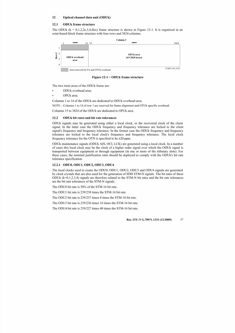
7/16/2019 G-709 ITU_T
http://slidepdf.com/reader/full/g-709-itut 45/218
Rec. ITU-T G.709/Y.1331 (12/2009) 37
12 Optical channel data unit (ODUk)
12.1 ODUk frame structure
The ODUk (k = 0,1,2,2e,3,4,flex) frame structure is shown in Figure 12-1. It is organized in an
octet-based block frame structure with four rows and 3824 columns.
G.709/Y.1331_F12-1Area reserved for FA and OTUk overhead.
OPUk area
(4 × 3810 bytes)ODUk overhead
area
1
2
3
4
1 14 15 3824
R o w
#
Column #
Figure 12-1 − ODUk frame structure
The two main areas of the ODUk frame are:
• ODUk overhead area;
• OPUk area.
Columns 1 to 14 of the ODUk are dedicated to ODUk overhead area.
NOTE – Columns 1 to 14 of row 1 are reserved for frame alignment and OTUk specific overhead.
Columns 15 to 3824 of the ODUk are dedicated to OPUk area.
12.2 ODUk bit rates and bit rate tolerances
ODUk signals may be generated using either a local clock, or the recovered clock of the client
signal. In the latter case the ODUk frequency and frequency tolerance are locked to the client
signal's frequency and frequency tolerance. In the former case the ODUk frequency and frequency
tolerance are locked to the local clock's frequency and frequency tolerance. The local clock
frequency tolerance for the OTN is specified to be ±20 ppm.
ODUk maintenance signals (ODUk AIS, OCI, LCK) are generated using a local clock. In a number
of cases this local clock may be the clock of a higher order signal over which the ODUk signal is
transported between equipment or through equipment (in one or more of the tributary slots). For
these cases, the nominal justification ratio should be deployed to comply with the ODUk's bit rate
tolerance specification.
12.2.1 ODU0, ODU1, ODU2, ODU3, ODU4
The local clocks used to create the ODU0, ODU1, ODU2, ODU3 and ODU4 signals are generated
by clock crystals that are also used for the generation of SDH STM-N signals. The bit rates of these
ODUk (k=0,1,2,3,4) signals are therefore related to the STM-N bit rates and the bit rate tolerances
are the bit rate tolerances of the STM-N signals.
The ODU0 bit rate is 50% of the STM-16 bit rate.
The ODU1 bit rate is 239/238 times the STM-16 bit rate.
The ODU2 bit rate is 239/237 times 4 times the STM-16 bit rate.
The ODU3 bit rate is 239/236 times 16 times the STM-16 bit rate.
The ODU4 bit rate is 239/227 times 40 times the STM-16 bit rate.
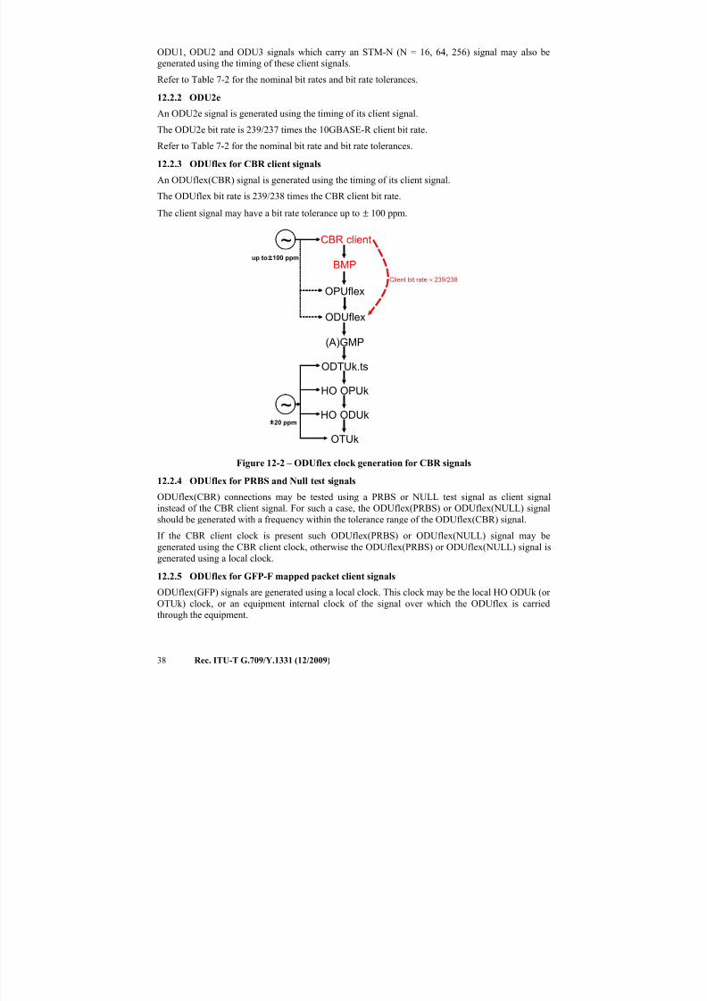
7/16/2019 G-709 ITU_T
http://slidepdf.com/reader/full/g-709-itut 46/218
38 Rec. ITU-T G.709/Y.1331 (12/2009)
ODU1, ODU2 and ODU3 signals which carry an STM-N (N = 16, 64, 256) signal may also be
generated using the timing of these client signals.
Refer to Table 7-2 for the nominal bit rates and bit rate tolerances.
12.2.2 ODU2e
An ODU2e signal is generated using the timing of its client signal.
The ODU2e bit rate is 239/237 times the 10GBASE-R client bit rate.
Refer to Table 7-2 for the nominal bit rate and bit rate tolerances.
12.2.3 ODUflex for CBR client signals
An ODUflex(CBR) signal is generated using the timing of its client signal.
The ODUflex bit rate is 239/238 times the CBR client bit rate.
The client signal may have a bit rate tolerance up to ± 100 ppm.
Figure 12-2 – ODUflex clock generation for CBR signals
12.2.4 ODUflex for PRBS and Null test signalsODUflex(CBR) connections may be tested using a PRBS or NULL test signal as client signal
instead of the CBR client signal. For such a case, the ODUflex(PRBS) or ODUflex(NULL) signal
should be generated with a frequency within the tolerance range of the ODUflex(CBR) signal.
If the CBR client clock is present such ODUflex(PRBS) or ODUflex(NULL) signal may be
generated using the CBR client clock, otherwise the ODUflex(PRBS) or ODUflex(NULL) signal is
generated using a local clock.
12.2.5 ODUflex for GFP-F mapped packet client signals
ODUflex(GFP) signals are generated using a local clock. This clock may be the local HO ODUk (or
OTUk) clock, or an equipment internal clock of the signal over which the ODUflex is carriedthrough the equipment.
CBR client
BMP
OPUflex
(A)GMP
ODTUk.ts
HO OPUk
Client bit rate × 239/238
HO ODUk
OTUk
~
~
±20 ppm
up to ±100 ppm
ODUflex
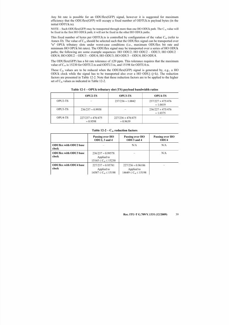
7/16/2019 G-709 ITU_T
http://slidepdf.com/reader/full/g-709-itut 47/218
Rec. ITU-T G.709/Y.1331 (12/2009) 39
Any bit rate is possible for an ODUflex(GFP) signal, however it is suggested for maximum
efficiency that the ODUflex(GFP) will occupy a fixed number of ODTUk.ts payload bytes (in the
initial ODTUk.ts).
NOTE – Such ODUflex(GFP) may be transported through more than one HO ODUk path. The Cm value will
be fixed in the first HO ODUk path; it will not be fixed in the other HO ODUk paths.
This fixed number of bytes per ODTUk.ts is controlled by configuration of the value Cm (refer to
Annex D). The value of Cm should be selected such that the ODUflex signal can be transported over
"n" OPUk tributary slots under worst-case conditions (i.e., maximum ODUflex bit rate and
minimum HO OPUk bit rates). The ODUflex signal may be transported over a series of HO ODUk
paths; the following are some example sequences: HO ODU2; HO ODU2 – ODU3; HO ODU2 –
ODU4; HO ODU2 – ODU3 – ODU4; HO ODU3; HO ODU3 – ODU4; HO ODU4.
The ODUflex(GFP) has a bit rate tolerance of ±20 ppm. This tolerance requires that the maximum
value of Cm is 15230 for ODTU2.ts and ODTU3.ts, and 15198 for ODTU4.ts.
These Cm values are to be reduced when the ODUflex(GFP) signal is generated by, e.g., a HO
ODUk clock while the signal has to be transported also over a HO ODUj (j<k). The reduction
factors are presented in Table 12-2. Note that these reduction factors are to be applied to the higher set of Cm values as indicated in Table 12-2.
Table 12-1 – OPUk tributary slot (TS) payload bandwidth ratios
OPU2-TS OPU3-TS OPU4-TS
OPU2-TS – 237/236 ≈ 1.0042 237/227 × 475/476
≈ 1.0419
OPU3-TS 236/237 ≈ 0.9958 – 236/227 × 475/476
≈ 1.0375
OPU4-TS 227/237 × 476/475≈ 0.9598
227/236 × 476/475≈ 0.9639
–
Table 12-2 – Cm reduction factors
Passing over HO
ODU2, 3 and 4
Passing over HO
ODU3 and 4
Passing over HO
ODU4
ODUflex with ODU2 base
clock
– N/A N/A
ODUflex with ODU3 base
clock
236/237 ≈ 0.99578
Applied to15165 ≤ Cm ≤ 15230
– N/A
ODUflex with ODU4 base
clock 227/237 ≈ 0.95781
Applied to
14587 ≤ Cm ≤ 15198
227/236 ≈ 0.96186
Applied to
14649 ≤ Cm ≤ 15198
–
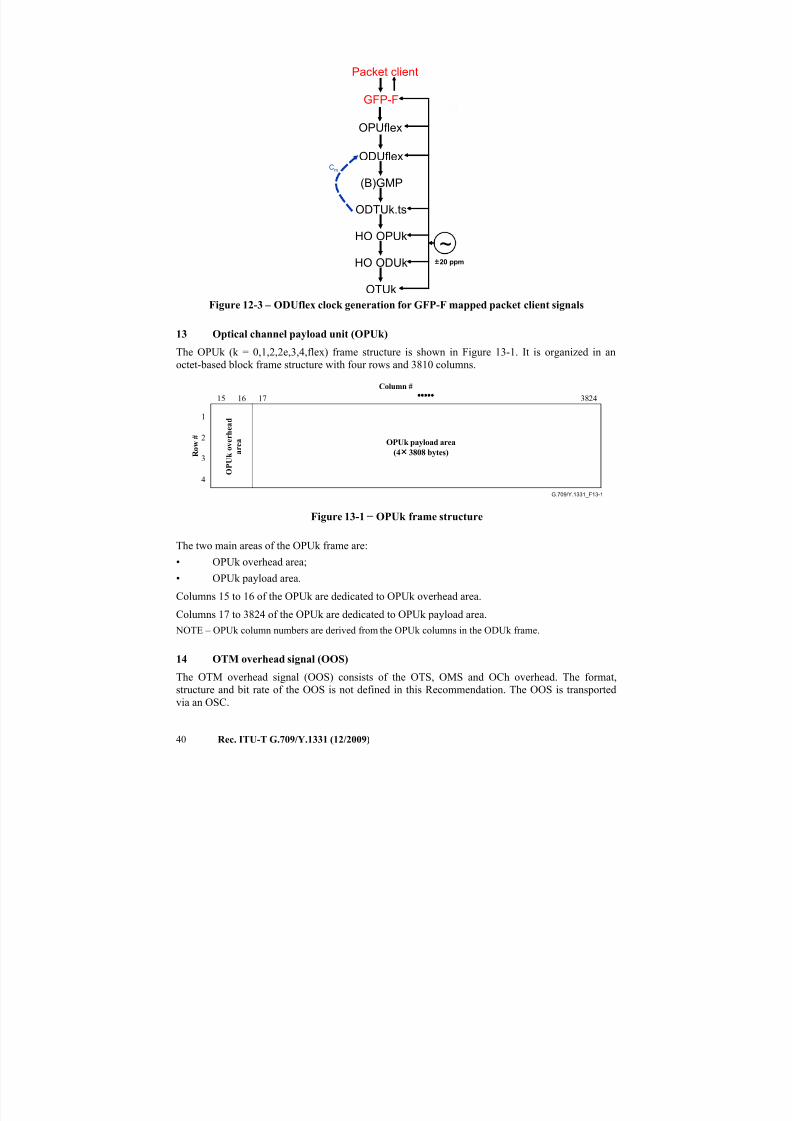
7/16/2019 G-709 ITU_T
http://slidepdf.com/reader/full/g-709-itut 48/218
40 Rec. ITU-T G.709/Y.1331 (12/2009)
Figure 12-3 – ODUflex clock generation for GFP-F mapped packet client signals
13 Optical channel payload unit (OPUk)
The OPUk (k = 0,1,2,2e,3,4,flex) frame structure is shown in Figure 13-1. It is organized in an
octet-based block frame structure with four rows and 3810 columns.
G.709/Y.1331_F13-1
O P U k o v e r h e a d
a r e a OPUk payload area
(4 × 3808 bytes)
1
2
3
4
16 17 382415
R o w
#
Column #
Figure 13-1 − OPUk frame structure
The two main areas of the OPUk frame are:
• OPUk overhead area;
• OPUk payload area.
Columns 15 to 16 of the OPUk are dedicated to OPUk overhead area.
Columns 17 to 3824 of the OPUk are dedicated to OPUk payload area.
NOTE – OPUk column numbers are derived from the OPUk columns in the ODUk frame.
14 OTM overhead signal (OOS)
The OTM overhead signal (OOS) consists of the OTS, OMS and OCh overhead. The format,structure and bit rate of the OOS is not defined in this Recommendation. The OOS is transported
via an OSC.
Packet client
GFP-F
ODUflex
(B)GMP
ODTUk.ts
HO OPUk
HO ODUk
OTUk
~±20 ppm
Cm
OPUflex
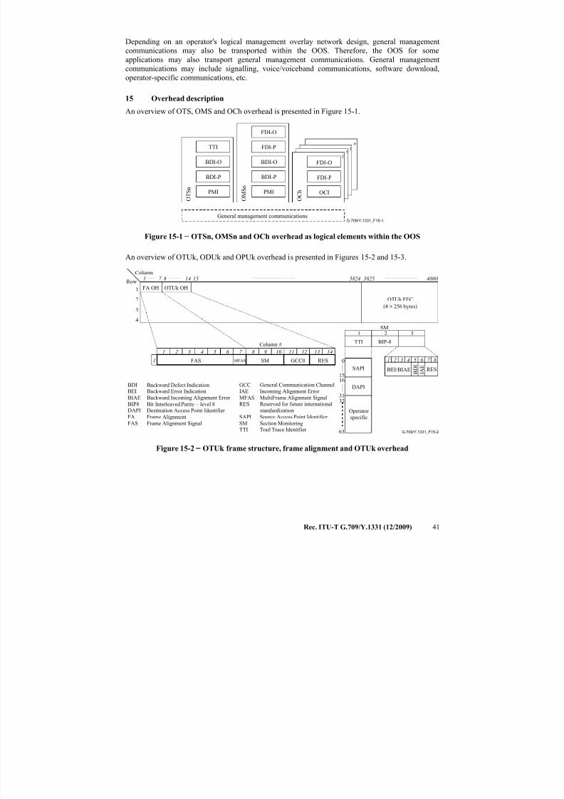
7/16/2019 G-709 ITU_T
http://slidepdf.com/reader/full/g-709-itut 49/218
Rec. ITU-T G.709/Y.1331 (12/2009) 41
Depending on an operator's logical management overlay network design, general management
communications may also be transported within the OOS. Therefore, the OOS for some
applications may also transport general management communications. General management
communications may include signalling, voice/voiceband communications, software download,
operator-specific communications, etc.
15 Overhead description
An overview of OTS, OMS and OCh overhead is presented in Figure 15-1.
G.709/Y.1331_F15-1General management communications
BDI-O
BDI-P
PMI O T S n
FDI-P
BDI-P
PMI O M
S n
FDI-O
FDI-O
FDI-P
OCI O C h
1
n
23TTI
BDI-O
Figure 15-1 − OTSn, OMSn and OCh overhead as logical elements within the OOS
An overview of OTUk, ODUk and OPUk overhead is presented in Figures 15-2 and 15-3.
G.709/Y.1331_F15-2
Row
Column
Column #
OTUk FEC
(4 × 256 bytes)
Operator
specific
TTI BIP-8
BEI/BIAE B D I
RES
1 2 3 4 5 6 7 8
1 2 3SM
12
3
4
1 14 15 3824
OTUk OH
3825 4080
1
1 2 3 4 5 6 7 8
FAS MFAS SM
9 10 11 12 13 14
RESGCC0
I A E
FA OH
7 8
63
32
0
1516
31
SAPI
DAPIBDI Backward Defect IndicationBEI Backward Error Indication
BIAE Backward Incoming Alignment Error
BIP8 Bit Interleaved Parity – level 8DAPI Destination Access Point Identifier
FA Frame Alignment
FAS Frame Alignment Signal
GCC General Communication Channel
IAE Incoming Alignment Error
MFAS MultiFrame Alignment SignalRES Reserved for future international
standardization
SAPI Source Access Point Identifier
SM Section MonitoringTTI Trail Trace Identifier
Figure 15-2 − OTUk frame structure, frame alignment and OTUk overhead
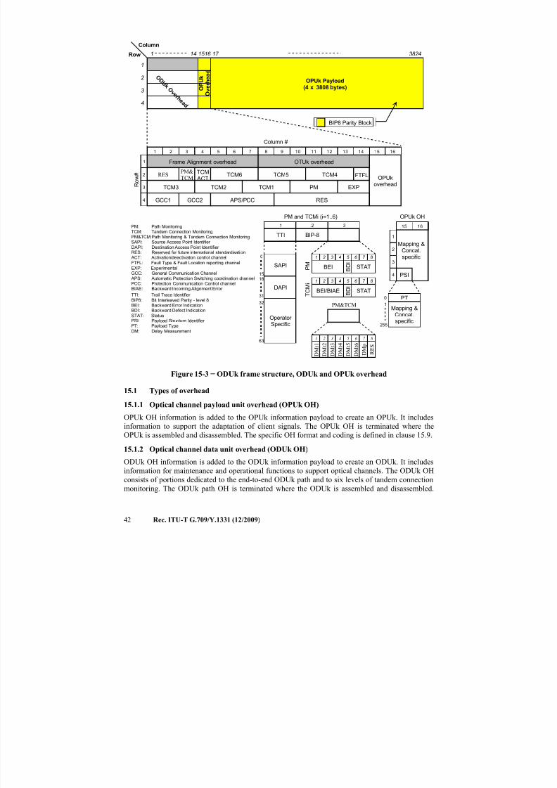
7/16/2019 G-709 ITU_T
http://slidepdf.com/reader/full/g-709-itut 50/218
42 Rec. ITU-T G.709/Y.1331 (12/2009)
1
2
3
4
1 2 3 4 5 6 7 8
Frame Alignment overhead
Column #
OPUkoverhead
OTUk overhead
9 10 11 12 13 14 15 16
R o w
#
EXP
TCM ACT
TCM5 TCM4
TCM3 TCM2 TCM1
TCM6
GCC1 GCC2
FTFL
PM
RES
1
2
3
4
1 16 17 3824Row
Column
O D U k O
v e r h e a d
OPUk Payload(4 x 3808 bytes)
PM: Path MonitoringTCM: Tandem Connection MonitoringPM&TCM:Path Monitoring & Tandem Connection MonitoringSAPI: Source Access Point Identifier DAPI: Destination Access Point Identifier RES: Reserved for future international standardisation
ACT: Activation/deactivation control channel
BIP8 Parity Block
15 14
O P U k
O
v e r h e a d
APS/PCC
63
TTI BIP-8
32
0
1516
BEI B D I
STAT
1 2 3 4 5 6 7 8
1 2 3
PM and TCMi (i=1..6)
FTFL: Fault Type & Fault Location reporting channelEXP: ExperimentalGCC: General Communication Channel
APS: Automatic Protection Switching coordination channelPCC: Protection Communication Control channelBIAE: Backward Incoming Alignment Error
TTI: Trail Trace Identifier BIP8: Bit Interleaved Parity - level 8BEI: Backward Error IndicationBDI: Backward Defect IndicationSTAT: StatusPSI: Payload Structure Identifier PT: Payload TypeDM: Delay Measurement
PSI
Mapping &Concat.specific
OPUk OH
15 16
1
2
3
4
Mapping &Concat.specific
255
0
1
PT31
SAPI
DAPI
Operator Specific
BEI/BIAE B D I STAT
1 2 3 4 5 6 7 8
P M
T C M
i
RESPM&
TCM
1 2 3 4 5 6 7 8
D M t 1
D M t 2
D M t 3
D M t 4
D M t 5
D M t 6
PM&TCM
D M p
R E S
Figure 15-3 − ODUk frame structure, ODUk and OPUk overhead
15.1 Types of overhead
15.1.1 Optical channel payload unit overhead (OPUk OH)
OPUk OH information is added to the OPUk information payload to create an OPUk. It includes
information to support the adaptation of client signals. The OPUk OH is terminated where the
OPUk is assembled and disassembled. The specific OH format and coding is defined in clause 15.9.
15.1.2 Optical channel data unit overhead (ODUk OH)
ODUk OH information is added to the ODUk information payload to create an ODUk. It includes
information for maintenance and operational functions to support optical channels. The ODUk OH
consists of portions dedicated to the end-to-end ODUk path and to six levels of tandem connectionmonitoring. The ODUk path OH is terminated where the ODUk is assembled and disassembled.
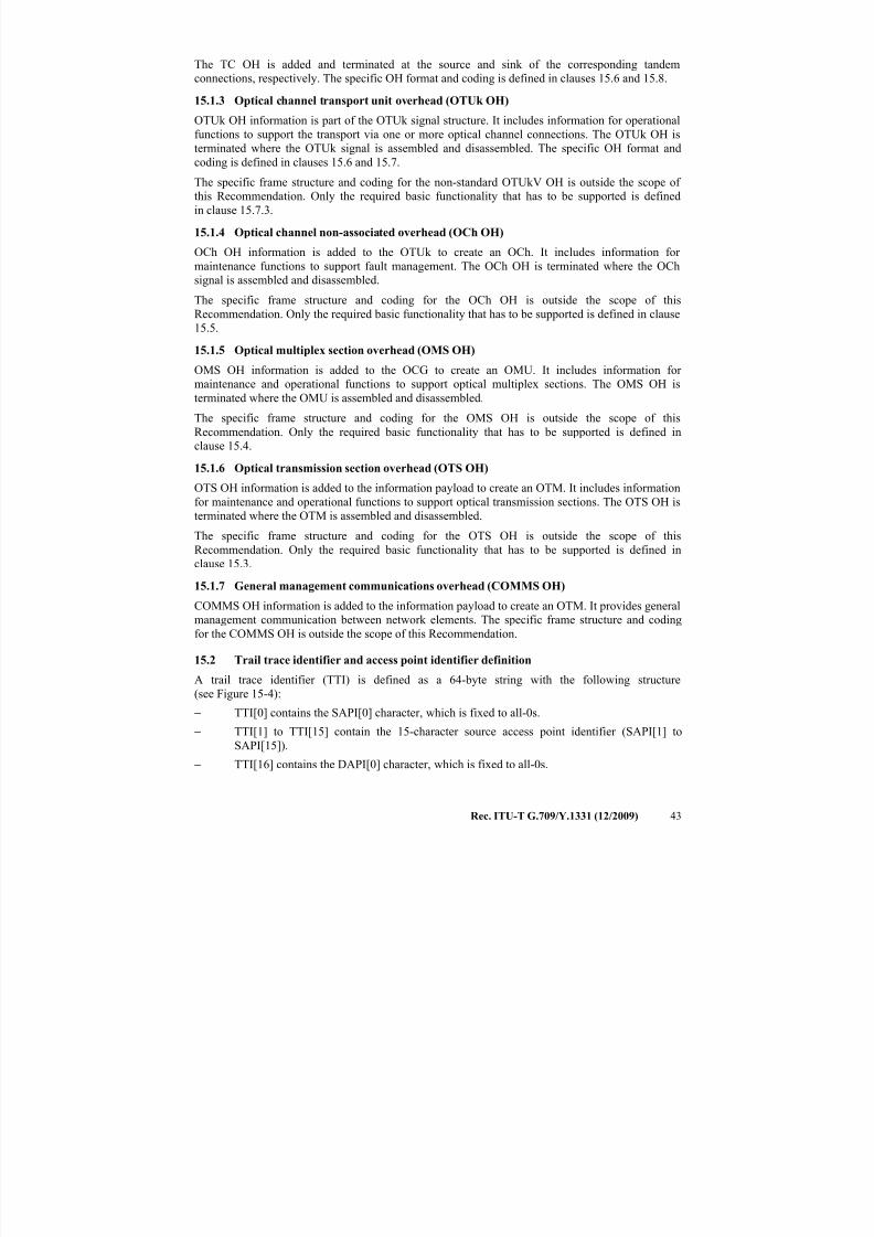
7/16/2019 G-709 ITU_T
http://slidepdf.com/reader/full/g-709-itut 51/218
Rec. ITU-T G.709/Y.1331 (12/2009) 43
The TC OH is added and terminated at the source and sink of the corresponding tandem
connections, respectively. The specific OH format and coding is defined in clauses 15.6 and 15.8.
15.1.3 Optical channel transport unit overhead (OTUk OH)
OTUk OH information is part of the OTUk signal structure. It includes information for operational
functions to support the transport via one or more optical channel connections. The OTUk OH is
terminated where the OTUk signal is assembled and disassembled. The specific OH format andcoding is defined in clauses 15.6 and 15.7.
The specific frame structure and coding for the non-standard OTUkV OH is outside the scope of
this Recommendation. Only the required basic functionality that has to be supported is defined
in clause 15.7.3.
15.1.4 Optical channel non-associated overhead (OCh OH)
OCh OH information is added to the OTUk to create an OCh. It includes information for
maintenance functions to support fault management. The OCh OH is terminated where the OCh
signal is assembled and disassembled.
The specific frame structure and coding for the OCh OH is outside the scope of thisRecommendation. Only the required basic functionality that has to be supported is defined in clause
15.5.
15.1.5 Optical multiplex section overhead (OMS OH)
OMS OH information is added to the OCG to create an OMU. It includes information for
maintenance and operational functions to support optical multiplex sections. The OMS OH is
terminated where the OMU is assembled and disassembled.
The specific frame structure and coding for the OMS OH is outside the scope of this
Recommendation. Only the required basic functionality that has to be supported is defined in
clause 15.4.15.1.6 Optical transmission section overhead (OTS OH)
OTS OH information is added to the information payload to create an OTM. It includes information
for maintenance and operational functions to support optical transmission sections. The OTS OH is
terminated where the OTM is assembled and disassembled.
The specific frame structure and coding for the OTS OH is outside the scope of this
Recommendation. Only the required basic functionality that has to be supported is defined in
clause 15.3.
15.1.7 General management communications overhead (COMMS OH)
COMMS OH information is added to the information payload to create an OTM. It provides general
management communication between network elements. The specific frame structure and coding
for the COMMS OH is outside the scope of this Recommendation.
15.2 Trail trace identifier and access point identifier definition
A trail trace identifier (TTI) is defined as a 64-byte string with the following structure
(see Figure 15-4):
− TTI[0] contains the SAPI[0] character, which is fixed to all-0s.
− TTI[1] to TTI[15] contain the 15-character source access point identifier (SAPI[1] to
SAPI[15]).− TTI[16] contains the DAPI[0] character, which is fixed to all-0s.
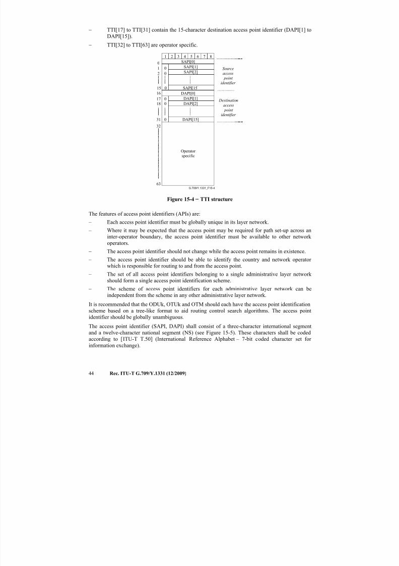
7/16/2019 G-709 ITU_T
http://slidepdf.com/reader/full/g-709-itut 52/218
44 Rec. ITU-T G.709/Y.1331 (12/2009)
− TTI[17] to TTI[31] contain the 15-character destination access point identifier (DAPI[1] to
DAPI[15]).
− TTI[32] to TTI[63] are operator specific.
G.709/Y.1331_F15-4
Sourceaccess point
identifier
Destination
access point
identifier
Operator specific
SAPI[0]
1 2 3 4 5 6 7 8
SAPI[1]SAPI[2]
SAPI[15]
00
0
12
15
0
DAPI[0]
DAPI[1]
DAPI[2]
DAPI[15]
00
0
17
18
31
16
32
63
Figure 15-4 − TTI structure
The features of access point identifiers (APIs) are:
– Each access point identifier must be globally unique in its layer network.
– Where it may be expected that the access point may be required for path set-up across an
inter-operator boundary, the access point identifier must be available to other network
operators.
– The access point identifier should not change while the access point remains in existence.
– The access point identifier should be able to identify the country and network operator
which is responsible for routing to and from the access point.
– The set of all access point identifiers belonging to a single administrative layer network should form a single access point identification scheme.
– The scheme of access point identifiers for each administrative layer network can be
independent from the scheme in any other administrative layer network.
It is recommended that the ODUk, OTUk and OTM should each have the access point identification
scheme based on a tree-like format to aid routing control search algorithms. The access point
identifier should be globally unambiguous.
The access point identifier (SAPI, DAPI) shall consist of a three-character international segment
and a twelve-character national segment (NS) (see Figure 15-5). These characters shall be coded
according to [ITU-T T.50] (International Reference Alphabet – 7-bit coded character set for
information exchange).
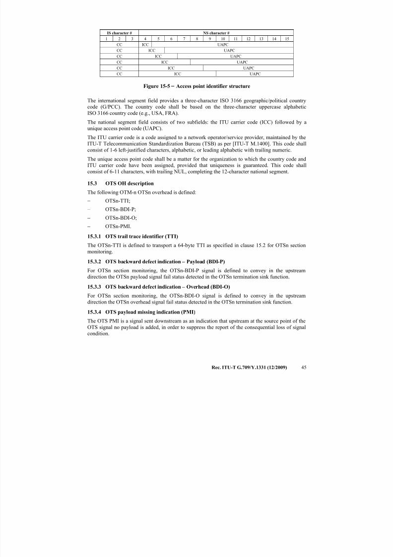
7/16/2019 G-709 ITU_T
http://slidepdf.com/reader/full/g-709-itut 53/218
Rec. ITU-T G.709/Y.1331 (12/2009) 45
IS character # NS character #
1 2 3 4 5 6 7 8 9 10 11 12 13 14 15
CC ICC UAPC
CC ICC UAPC
CC ICC UAPC
CC ICC UAPC
CC ICC UAPC
CC ICC UAPC
Figure 15-5 − Access point identifier structure
The international segment field provides a three-character ISO 3166 geographic/political country
code (G/PCC). The country code shall be based on the three-character uppercase alphabetic
ISO 3166 country code (e.g., USA, FRA).
The national segment field consists of two subfields: the ITU carrier code (ICC) followed by a
unique access point code (UAPC).
The ITU carrier code is a code assigned to a network operator/service provider, maintained by the
ITU-T Telecommunication Standardization Bureau (TSB) as per [ITU-T M.1400]. This code shall
consist of 1-6 left-justified characters, alphabetic, or leading alphabetic with trailing numeric.
The unique access point code shall be a matter for the organization to which the country code and
ITU carrier code have been assigned, provided that uniqueness is guaranteed. This code shall
consist of 6-11 characters, with trailing NUL, completing the 12-character national segment.
15.3 OTS OH description
The following OTM-n OTSn overhead is defined:
− OTSn-TTI;− OTSn-BDI-P;
− OTSn-BDI-O;
− OTSn-PMI.
15.3.1 OTS trail trace identifier (TTI)
The OTSn-TTI is defined to transport a 64-byte TTI as specified in clause 15.2 for OTSn section
monitoring.
15.3.2 OTS backward defect indication – Payload (BDI-P)
For OTSn section monitoring, the OTSn-BDI-P signal is defined to convey in the upstreamdirection the OTSn payload signal fail status detected in the OTSn termination sink function.
15.3.3 OTS backward defect indication – Overhead (BDI-O)
For OTSn section monitoring, the OTSn-BDI-O signal is defined to convey in the upstream
direction the OTSn overhead signal fail status detected in the OTSn termination sink function.
15.3.4 OTS payload missing indication (PMI)
The OTS PMI is a signal sent downstream as an indication that upstream at the source point of the
OTS signal no payload is added, in order to suppress the report of the consequential loss of signal
condition.
7/16/2019 G-709 ITU_T
http://slidepdf.com/reader/full/g-709-itut 54/218
46 Rec. ITU-T G.709/Y.1331 (12/2009)
15.4 OMS OH description
The following OTM-n OMSn overhead is defined:
− OMSn-FDI-P;
− OMSn-FDI-O;
− OMSn-BDI-P;
− OMSn-BDI-O;
− OMSn-PMI.
15.4.1 OMS forward defect indication – Payload (FDI-P)
For OMSn section monitoring, the OMSn-FDI-P signal is defined to convey in the downstream
direction the OMSn payload signal status (normal or failed).
15.4.2 OMS forward defect indication – Overhead (FDI-O)
For OMSn section monitoring, the OMSn-FDI-O signal is defined to convey in the downstream
direction the OMSn overhead signal status (normal or failed).
15.4.3 OMS backward defect indication – Payload (BDI-P)
For OMSn section monitoring, the OMSn-BDI-P signal is defined to convey in the upstream
direction the OMSn payload signal fail status detected in the OMSn termination sink function.
15.4.4 OMS backward defect indication – Overhead (BDI-O)
For OMSn section monitoring, the OMSn-BDI-O signal is defined to convey in the upstream
direction the OMSn overhead signal fail status detected in the OMSn termination sink function.
15.4.5 OMS payload missing indication (PMI)
The OMS PMI is a signal sent downstream as an indication that upstream at the source point of theOMS signal none of the OCCps contain an optical channel signal, in order to suppress the report of
the consequential loss of signal condition.
15.5 OCh OH description
The following OTM-n OCh overhead is defined:
− OCh-FDI-P;
− OCh-FDI-O;
− OCh-OCI.
15.5.1 OCh forward defect indication – Payload (FDI-P)For OCh trail monitoring, the OCh-FDI-P signal is defined to convey in the downstream direction
the OCh payload signal status (normal or failed).
15.5.2 OCh forward defect indication – Overhead (FDI-O)
For OCh trail monitoring, the OCh-FDI-O signal is defined to convey in the downstream direction
the OCh overhead signal status (normal or failed).
15.5.3 OCh open connection indication (OCI)
The OCh OCI is a signal sent downstream as an indication that upstream in a connection function
the matrix connection is opened as a result of a management command. The consequential detection
of the OCh loss of signal condition at the OCh termination point can now be related to an open
matrix.
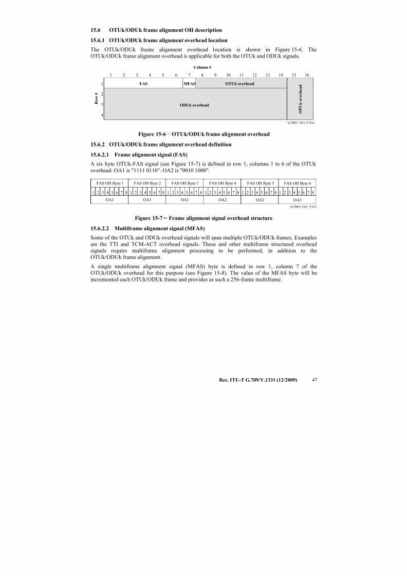
7/16/2019 G-709 ITU_T
http://slidepdf.com/reader/full/g-709-itut 55/218
Rec. ITU-T G.709/Y.1331 (12/2009) 47
15.6 OTUk/ODUk frame alignment OH description
15.6.1 OTUk/ODUk frame alignment overhead location
The OTUk/ODUk frame alignment overhead location is shown in Figure 15-6. The
OTUk/ODUk frame alignment overhead is applicable for both the OTUk and ODUk signals.
G.709/Y.1331_F15-6
R o w
#
ODUk overhead
O P U k o v e r h e a d
OTUk overhead
Column #
1
2
3
4
1 2 3 4 5 6 7 8
FAS MFAS
9 10 11 12 13 14 15 16
Figure 15-6 − OTUk/ODUk frame alignment overhead
15.6.2 OTUk/ODUk frame alignment overhead definition
15.6.2.1 Frame alignment signal (FAS)
A six byte OTUk-FAS signal (see Figure 15-7) is defined in row 1, columns 1 to 6 of the OTUk
overhead. OA1 is "1111 0110". OA2 is "0010 1000".
G.709/Y.1331_F15-7
FAS OH Byte 1 FAS OH Byte 2 FAS OH Byte 3 FAS OH Byte 4 FAS OH Byte 5 FAS OH Byte 6
1 2 3 4 5 6 7 8 1 2 3 4 5 6 7 8 1 2 3 4 5 6 7 8 1 2 3 4 5 6 7 8 1 2 3 4 5 6 7 8 1 2 3 4 5 6 7 8
OA1 OA1 OA1 OA2 OA2 OA2
Figure 15-7 − Frame alignment signal overhead structure
15.6.2.2 Multiframe alignment signal (MFAS)
Some of the OTUk and ODUk overhead signals will span multiple OTUk/ODUk frames. Examples
are the TTI and TCM-ACT overhead signals. These and other multiframe structured overhead
signals require multiframe alignment processing to be performed, in addition to the
OTUk/ODUk frame alignment.
A single multiframe alignment signal (MFAS) byte is defined in row 1, column 7 of the
OTUk/ODUk overhead for this purpose (see Figure 15-8). The value of the MFAS byte will be
incremented each OTUk/ODUk frame and provides as such a 256-frame multiframe.
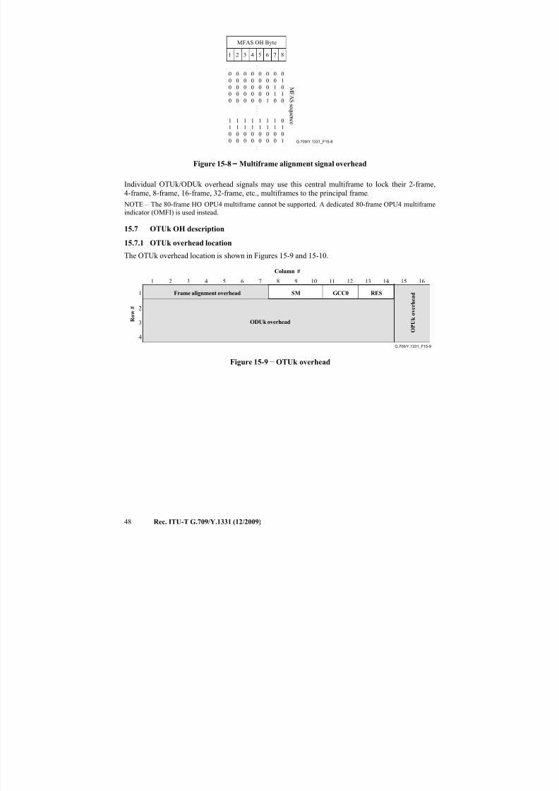
7/16/2019 G-709 ITU_T
http://slidepdf.com/reader/full/g-709-itut 56/218
48 Rec. ITU-T G.709/Y.1331 (12/2009)
G.709/Y.1331_F15-8
MFAS OH Byte
M
F A S s e q u e n c e
1 2 3 4 5 6 7 8
0 0 0 0 0 0 0 0
0 0 0 0 0 0 0 1
0 0 0 0 0 0 1 0
0 0 0 0 0 0 1 10 0 0 0 0 1 0 0....
.
.
1 1 1 1 1 1 1 0
1 1 1 1 1 1 1 1
0 0 0 0 0 0 0 0
0 0 0 0 0 0 0 1..
Figure 15-8 − Multiframe alignment signal overhead
Individual OTUk/ODUk overhead signals may use this central multiframe to lock their 2-frame,
4-frame, 8-frame, 16-frame, 32-frame, etc., multiframes to the principal frame.
NOTE – The 80-frame HO OPU4 multiframe cannot be supported. A dedicated 80-frame OPU4 multiframe
indicator (OMFI) is used instead.
15.7 OTUk OH description
15.7.1 OTUk overhead location
The OTUk overhead location is shown in Figures 15-9 and 15-10.
G.709/Y.1331_F15-9
Frame alignment overhead
Column #
R o w
#
ODUk overhead
O P U k o v e r h e a d
1 2 3 4 5 6 7 8 9 10 11 12 13 14 15 16
1
2
3
4
GCC0SM RES
Figure 15-9 − OTUk overhead
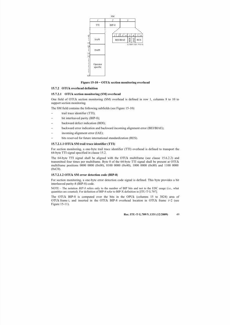
7/16/2019 G-709 ITU_T
http://slidepdf.com/reader/full/g-709-itut 57/218
Rec. ITU-T G.709/Y.1331 (12/2009) 49
G.709/Y.1331_F15-10
Operator specific
TTI BIP-8
BEI/BIAE B D
IRES
1 2 3 4 5 6 7 8
1 2 3
SM
I A E
63
32
0
15
16
31
SAPI
DAPI
Figure 15-10 − OTUk section monitoring overhead
15.7.2 OTUk overhead definition
15.7.2.1 OTUk section monitoring (SM) overhead
One field of OTUk section monitoring (SM) overhead is defined in row 1, columns 8 to 10 to
support section monitoring.
The SM field contains the following subfields (see Figure 15-10):
− trail trace identifier (TTI);
− bit interleaved parity (BIP-8);− backward defect indication (BDI);
− backward error indication and backward incoming alignment error (BEI/BIAE);
− incoming alignment error (IAE);
− bits reserved for future international standardization (RES).
15.7.2.1.1 OTUk SM trail trace identifier (TTI)
For section monitoring, a one-byte trail trace identifier (TTI) overhead is defined to transport the
64-byte TTI signal specified in clause 15.2.
The 64-byte TTI signal shall be aligned with the OTUk multiframe (see clause 15.6.2.2) andtransmitted four times per multiframe. Byte 0 of the 64-byte TTI signal shall be present at OTUk
multiframe positions 0000 0000 (0x00), 0100 0000 (0x40), 1000 0000 (0x80) and 1100 0000
(0xC0).
15.7.2.1.2 OTUk SM error detection code (BIP-8)
For section monitoring, a one-byte error detection code signal is defined. This byte provides a bit
interleaved parity-8 (BIP-8) code.
NOTE – The notation BIP-8 refers only to the number of BIP bits and not to the EDC usage (i.e., what
quantities are counted). For definition of BIP-8 refer to BIP-X definition in [ITU-T G.707].
The OTUk BIP-8 is computed over the bits in the OPUk (columns 15 to 3824) area of OTUk frame i, and inserted in the OTUk BIP-8 overhead location in OTUk frame i+2 (see
Figure 15-11).
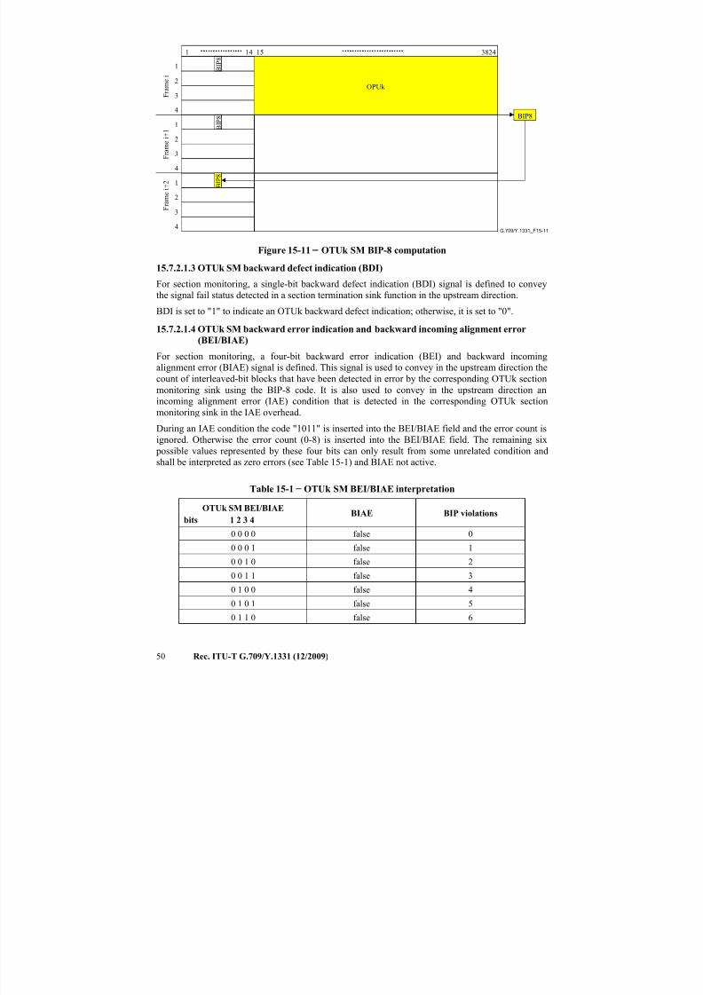
7/16/2019 G-709 ITU_T
http://slidepdf.com/reader/full/g-709-itut 58/218
50 Rec. ITU-T G.709/Y.1331 (12/2009)
G.709/Y.1331_F15-11
1 14 15 3824
BIP8
B I P 8
OPUk
B I P 8
B I P 8
F r a m e i
F r a m e i + 1
F r a m e i + 2
1
2
3
4
1
2
3
4
1
2
3
4
Figure 15-11 − OTUk SM BIP-8 computation
15.7.2.1.3 OTUk SM backward defect indication (BDI)
For section monitoring, a single-bit backward defect indication (BDI) signal is defined to convey
the signal fail status detected in a section termination sink function in the upstream direction.
BDI is set to "1" to indicate an OTUk backward defect indication; otherwise, it is set to "0".
15.7.2.1.4 OTUk SM backward error indication and backward incoming alignment error
(BEI/BIAE)
For section monitoring, a four-bit backward error indication (BEI) and backward incoming
alignment error (BIAE) signal is defined. This signal is used to convey in the upstream direction the
count of interleaved-bit blocks that have been detected in error by the corresponding OTUk section
monitoring sink using the BIP-8 code. It is also used to convey in the upstream direction an
incoming alignment error (IAE) condition that is detected in the corresponding OTUk section
monitoring sink in the IAE overhead.
During an IAE condition the code "1011" is inserted into the BEI/BIAE field and the error count is
ignored. Otherwise the error count (0-8) is inserted into the BEI/BIAE field. The remaining six
possible values represented by these four bits can only result from some unrelated condition and
shall be interpreted as zero errors (see Table 15-1) and BIAE not active.
Table 15-1 − OTUk SM BEI/BIAE interpretation
OTUk SM BEI/BIAE
bits 1 2 3 4BIAE BIP violations
0 0 0 0 false 0
0 0 0 1 false 1
0 0 1 0 false 2
0 0 1 1 false 3
0 1 0 0 false 4
0 1 0 1 false 5
0 1 1 0 false 6
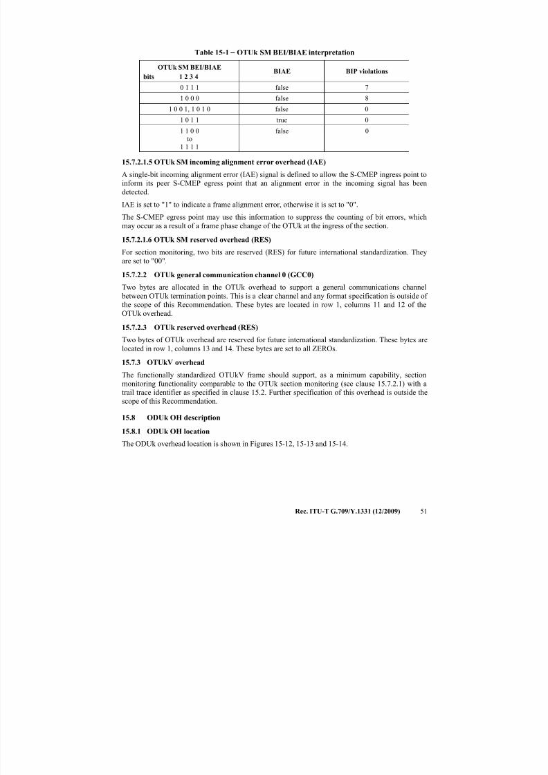
7/16/2019 G-709 ITU_T
http://slidepdf.com/reader/full/g-709-itut 59/218
Rec. ITU-T G.709/Y.1331 (12/2009) 51
Table 15-1 − OTUk SM BEI/BIAE interpretation
OTUk SM BEI/BIAE
bits 1 2 3 4BIAE BIP violations
0 1 1 1 false 7
1 0 0 0 false 8
1 0 0 1, 1 0 1 0 false 0
1 0 1 1 true 0
1 1 0 0
to
1 1 1 1
false 0
15.7.2.1.5 OTUk SM incoming alignment error overhead (IAE)
A single-bit incoming alignment error (IAE) signal is defined to allow the S-CMEP ingress point to
inform its peer S-CMEP egress point that an alignment error in the incoming signal has been
detected.
IAE is set to "1" to indicate a frame alignment error, otherwise it is set to "0".
The S-CMEP egress point may use this information to suppress the counting of bit errors, which
may occur as a result of a frame phase change of the OTUk at the ingress of the section.
15.7.2.1.6 OTUk SM reserved overhead (RES)
For section monitoring, two bits are reserved (RES) for future international standardization. They
are set to "00".
15.7.2.2 OTUk general communication channel 0 (GCC0)
Two bytes are allocated in the OTUk overhead to support a general communications channel
between OTUk termination points. This is a clear channel and any format specification is outside of
the scope of this Recommendation. These bytes are located in row 1, columns 11 and 12 of the
OTUk overhead.
15.7.2.3 OTUk reserved overhead (RES)
Two bytes of OTUk overhead are reserved for future international standardization. These bytes are
located in row 1, columns 13 and 14. These bytes are set to all ZEROs.
15.7.3 OTUkV overhead
The functionally standardized OTUkV frame should support, as a minimum capability, sectionmonitoring functionality comparable to the OTUk section monitoring (see clause 15.7.2.1) with a
trail trace identifier as specified in clause 15.2. Further specification of this overhead is outside the
scope of this Recommendation.
15.8 ODUk OH description
15.8.1 ODUk OH location
The ODUk overhead location is shown in Figures 15-12, 15-13 and 15-14.
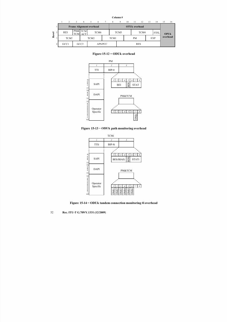
7/16/2019 G-709 ITU_T
http://slidepdf.com/reader/full/g-709-itut 60/218
52 Rec. ITU-T G.709/Y.1331 (12/2009)
1
2
3
4
1 2 3 4 5 6 7 8
Frame Alignment overhead
Column #
RESOPUk
overhead
OTUk overhead
9 10 11 12 13 14 15 16
R o w #
EXP
TCM
ACT
APS/PCC
TCM6 TCM5 TCM4
TCM3 TCM2 TCM1
GCC1 GCC2
FTFL
PM
RES
PM&
TCM
Figure 15-12 − ODUk overhead
TTI BIP-8
BEI B D I
STAT
1 2 3 4 5 6 7 8
1 2 3
PM
63
32
0
1516
31
SAPI
DAPI
Operator
Specific 1 2 3 4 5 6 7 8
D M
p
PM&TCM
Figure 15-13 − ODUk path monitoring overhead
TTIi BIP-8i
BEIi/BIAEi B D I i
STATi
1 2 3 4 5 6 7 8
1 2 3
TCMi
63
32
0
1516
31
SAPI
DAPI
Operator Specific 1 2 3 4 5 6 7 8
D M t 1
D M t 2
D M t 3
D M t 4
D M t 5
D M t 6
PM&TCM
Figure 15-14 − ODUk tandem connection monitoring #i overhead
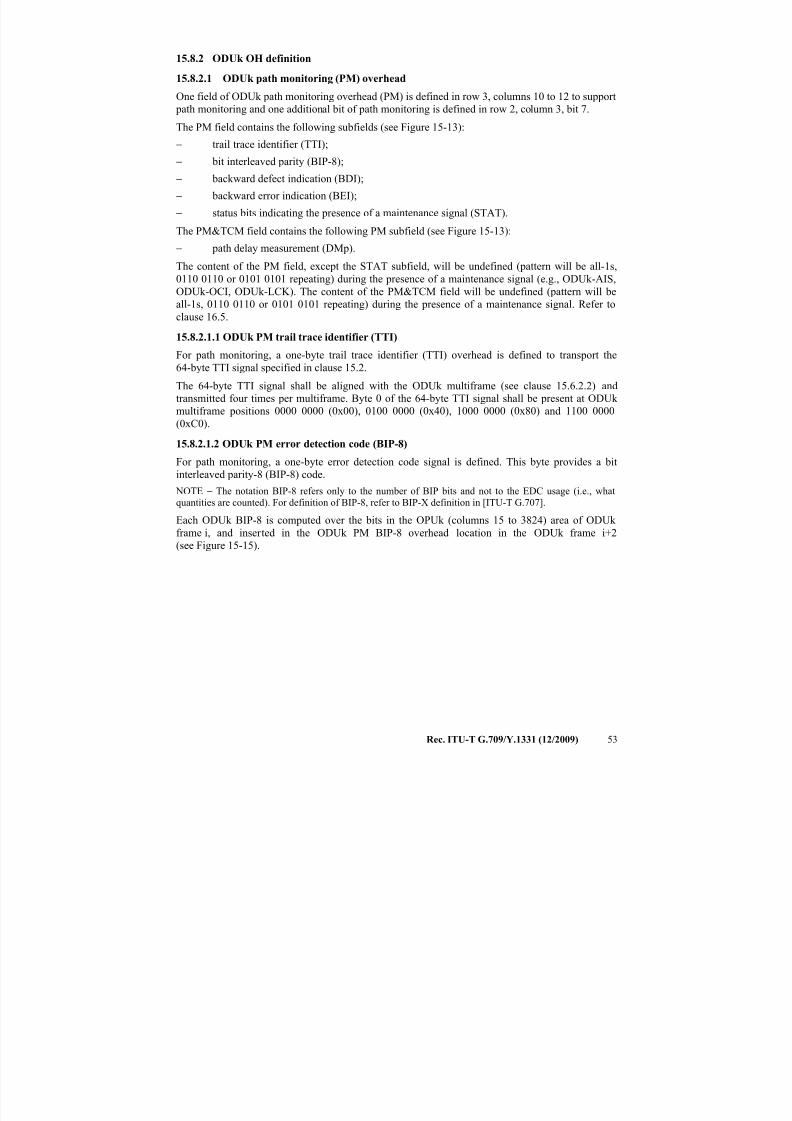
7/16/2019 G-709 ITU_T
http://slidepdf.com/reader/full/g-709-itut 61/218
Rec. ITU-T G.709/Y.1331 (12/2009) 53
15.8.2 ODUk OH definition
15.8.2.1 ODUk path monitoring (PM) overhead
One field of ODUk path monitoring overhead (PM) is defined in row 3, columns 10 to 12 to support
path monitoring and one additional bit of path monitoring is defined in row 2, column 3, bit 7.
The PM field contains the following subfields (see Figure 15-13):
− trail trace identifier (TTI);
− bit interleaved parity (BIP-8);
− backward defect indication (BDI);
− backward error indication (BEI);
− status bits indicating the presence of a maintenance signal (STAT).
The PM&TCM field contains the following PM subfield (see Figure 15-13):
− path delay measurement (DMp).
The content of the PM field, except the STAT subfield, will be undefined (pattern will be all-1s,
0110 0110 or 0101 0101 repeating) during the presence of a maintenance signal (e.g., ODUk-AIS,
ODUk-OCI, ODUk-LCK). The content of the PM&TCM field will be undefined (pattern will be
all-1s, 0110 0110 or 0101 0101 repeating) during the presence of a maintenance signal. Refer to
clause 16.5.
15.8.2.1.1 ODUk PM trail trace identifier (TTI)
For path monitoring, a one-byte trail trace identifier (TTI) overhead is defined to transport the
64-byte TTI signal specified in clause 15.2.
The 64-byte TTI signal shall be aligned with the ODUk multiframe (see clause 15.6.2.2) and
transmitted four times per multiframe. Byte 0 of the 64-byte TTI signal shall be present at ODUk
multiframe positions 0000 0000 (0x00), 0100 0000 (0x40), 1000 0000 (0x80) and 1100 0000(0xC0).
15.8.2.1.2 ODUk PM error detection code (BIP-8)
For path monitoring, a one-byte error detection code signal is defined. This byte provides a bit
interleaved parity-8 (BIP-8) code.
NOTE − The notation BIP-8 refers only to the number of BIP bits and not to the EDC usage (i.e., what
quantities are counted). For definition of BIP-8, refer to BIP-X definition in [ITU-T G.707].
Each ODUk BIP-8 is computed over the bits in the OPUk (columns 15 to 3824) area of ODUk
frame i, and inserted in the ODUk PM BIP-8 overhead location in the ODUk frame i+2
(see Figure 15-15).
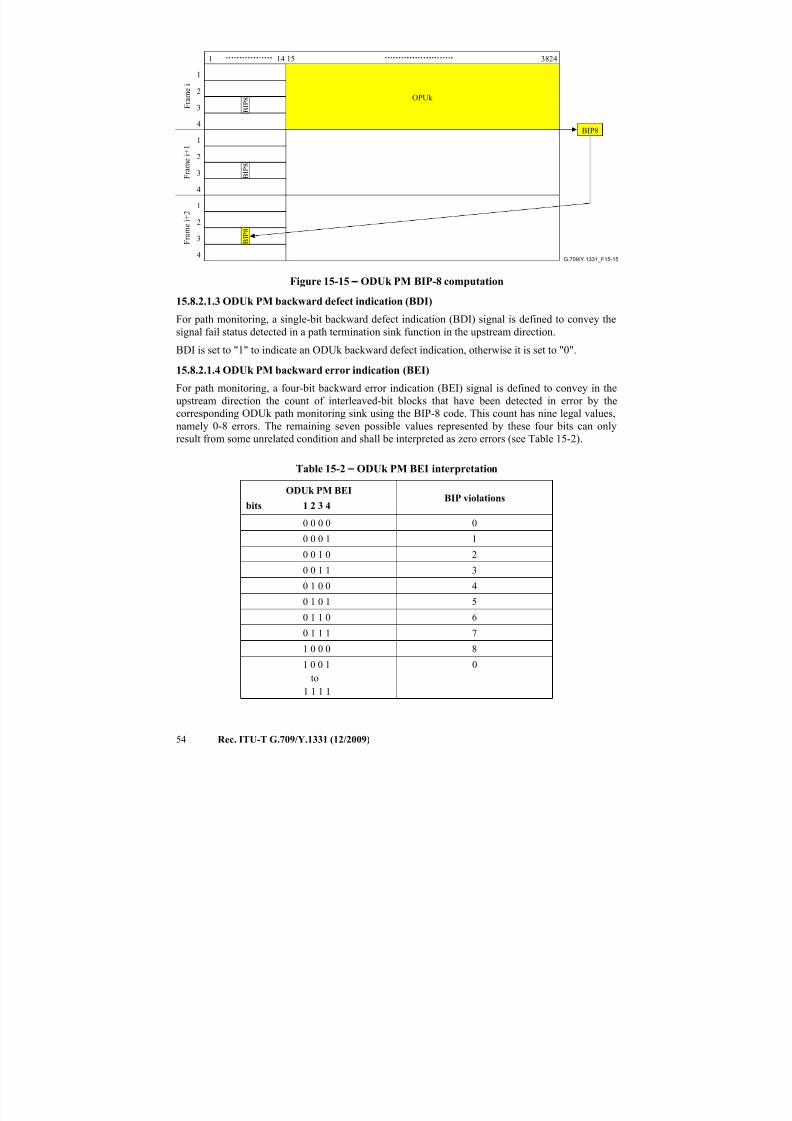
7/16/2019 G-709 ITU_T
http://slidepdf.com/reader/full/g-709-itut 62/218
54 Rec. ITU-T G.709/Y.1331 (12/2009)
G.709/Y.1331_F15-15
F r a m e i
F r a m e i + 1
F r a m e i + 2
1
2
3
4
1 3824
1
2
3
4
BIP8
B I P 8
OPUk
1
2
3
4
B I P 8
B I P 8
14 15
Figure 15-15 − ODUk PM BIP-8 computation
15.8.2.1.3 ODUk PM backward defect indication (BDI)
For path monitoring, a single-bit backward defect indication (BDI) signal is defined to convey the
signal fail status detected in a path termination sink function in the upstream direction.
BDI is set to "1" to indicate an ODUk backward defect indication, otherwise it is set to "0".
15.8.2.1.4 ODUk PM backward error indication (BEI)
For path monitoring, a four-bit backward error indication (BEI) signal is defined to convey in the
upstream direction the count of interleaved-bit blocks that have been detected in error by the
corresponding ODUk path monitoring sink using the BIP-8 code. This count has nine legal values,
namely 0-8 errors. The remaining seven possible values represented by these four bits can only
result from some unrelated condition and shall be interpreted as zero errors (see Table 15-2).
Table 15-2 − ODUk PM BEI interpretation
ODUk PM BEI
bits 1 2 3 4BIP violations
0 0 0 0 0
0 0 0 1 1
0 0 1 0 2
0 0 1 1 3
0 1 0 0 4
0 1 0 1 5
0 1 1 0 6
0 1 1 1 7
1 0 0 0 8
1 0 0 1
to1 1 1 1
0
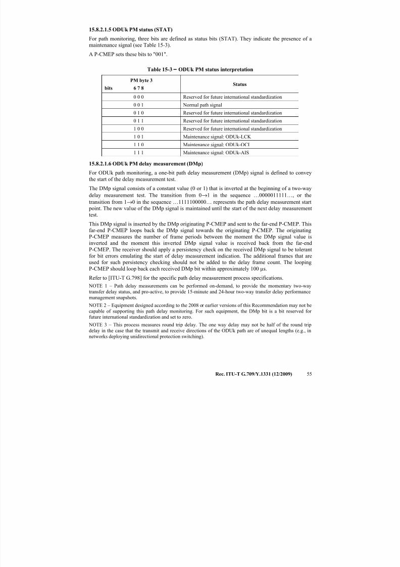
7/16/2019 G-709 ITU_T
http://slidepdf.com/reader/full/g-709-itut 63/218
Rec. ITU-T G.709/Y.1331 (12/2009) 55
15.8.2.1.5 ODUk PM status (STAT)
For path monitoring, three bits are defined as status bits (STAT). They indicate the presence of a
maintenance signal (see Table 15-3).
A P-CMEP sets these bits to "001".
Table 15-3 − ODUk PM status interpretation
PM byte 3
bits 6 7 8Status
0 0 0 Reserved for future international standardization
0 0 1 Normal path signal
0 1 0 Reserved for future international standardization
0 1 1 Reserved for future international standardization
1 0 0 Reserved for future international standardization
1 0 1 Maintenance signal: ODUk-LCK 1 1 0 Maintenance signal: ODUk-OCI
1 1 1 Maintenance signal: ODUk-AIS
15.8.2.1.6 ODUk PM delay measurement (DMp)
For ODUk path monitoring, a one-bit path delay measurement (DMp) signal is defined to convey
the start of the delay measurement test.
The DMp signal consists of a constant value (0 or 1) that is inverted at the beginning of a two-way
delay measurement test. The transition from 0→1 in the sequence …0000011111…, or the
transition from 1→0 in the sequence …1111100000… represents the path delay measurement start
point. The new value of the DMp signal is maintained until the start of the next delay measurementtest.
This DMp signal is inserted by the DMp originating P-CMEP and sent to the far-end P-CMEP. This
far-end P-CMEP loops back the DMp signal towards the originating P-CMEP. The originating
P-CMEP measures the number of frame periods between the moment the DMp signal value is
inverted and the moment this inverted DMp signal value is received back from the far-end
P-CMEP. The receiver should apply a persistency check on the received DMp signal to be tolerant
for bit errors emulating the start of delay measurement indication. The additional frames that are
used for such persistency checking should not be added to the delay frame count. The looping
P-CMEP should loop back each received DMp bit within approximately 100 µs.
Refer to [ITU-T G.798] for the specific path delay measurement process specifications.
NOTE 1 – Path delay measurements can be performed on-demand, to provide the momentary two-way
transfer delay status, and pro-active, to provide 15-minute and 24-hour two-way transfer delay performance
management snapshots.
NOTE 2 – Equipment designed according to the 2008 or earlier versions of this Recommendation may not be
capable of supporting this path delay monitoring. For such equipment, the DMp bit is a bit reserved for
future international standardization and set to zero.
NOTE 3 – This process measures round trip delay. The one way delay may not be half of the round trip
delay in the case that the transmit and receive directions of the ODUk path are of unequal lengths (e.g., in
networks deploying unidirectional protection switching).
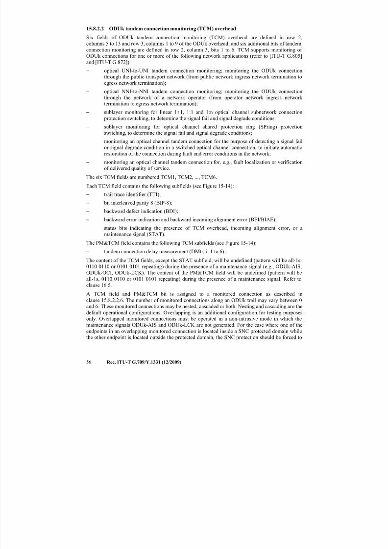
7/16/2019 G-709 ITU_T
http://slidepdf.com/reader/full/g-709-itut 64/218
56 Rec. ITU-T G.709/Y.1331 (12/2009)
15.8.2.2 ODUk tandem connection monitoring (TCM) overhead
Six fields of ODUk tandem connection monitoring (TCM) overhead are defined in row 2,
columns 5 to 13 and row 3, columns 1 to 9 of the ODUk overhead; and six additional bits of tandem
connection monitoring are defined in row 2, column 3, bits 1 to 6. TCM supports monitoring of
ODUk connections for one or more of the following network applications (refer to [ITU-T G.805]
and [ITU-T G.872]):
− optical UNI-to-UNI tandem connection monitoring; monitoring the ODUk connection
through the public transport network (from public network ingress network termination to
egress network termination);
− optical NNI-to-NNI tandem connection monitoring; monitoring the ODUk connection
through the network of a network operator (from operator network ingress network
termination to egress network termination);
− sublayer monitoring for linear 1+1, 1:1 and 1:n optical channel subnetwork connection
protection switching, to determine the signal fail and signal degrade conditions;
− sublayer monitoring for optical channel shared protection ring (SPring) protection
switching, to determine the signal fail and signal degrade conditions;− monitoring an optical channel tandem connection for the purpose of detecting a signal fail
or signal degrade condition in a switched optical channel connection, to initiate automatic
restoration of the connection during fault and error conditions in the network;
− monitoring an optical channel tandem connection for, e.g., fault localization or verification
of delivered quality of service.
The six TCM fields are numbered TCM1, TCM2, ..., TCM6.
Each TCM field contains the following subfields (see Figure 15-14):
− trail trace identifier (TTI);
− bit interleaved parity 8 (BIP-8);
− backward defect indication (BDI);
− backward error indication and backward incoming alignment error (BEI/BIAE);
− status bits indicating the presence of TCM overhead, incoming alignment error, or a
maintenance signal (STAT).
The PM&TCM field contains the following TCM subfields (see Figure 15-14):
− tandem connection delay measurement (DMti, i=1 to 6).
The content of the TCM fields, except the STAT subfield, will be undefined (pattern will be all-1s,
0110 0110 or 0101 0101 repeating) during the presence of a maintenance signal (e.g., ODUk-AIS,ODUk-OCI, ODUk-LCK). The content of the PM&TCM field will be undefined (pattern will be
all-1s, 0110 0110 or 0101 0101 repeating) during the presence of a maintenance signal. Refer to
clause 16.5.
A TCM field and PM&TCM bit is assigned to a monitored connection as described in
clause 15.8.2.2.6. The number of monitored connections along an ODUk trail may vary between 0
and 6. These monitored connections may be nested, cascaded or both. Nesting and cascading are the
default operational configurations. Overlapping is an additional configuration for testing purposes
only. Overlapped monitored connections must be operated in a non-intrusive mode in which the
maintenance signals ODUk-AIS and ODUk-LCK are not generated. For the case where one of the
endpoints in an overlapping monitored connection is located inside a SNC protected domain whilethe other endpoint is located outside the protected domain, the SNC protection should be forced to
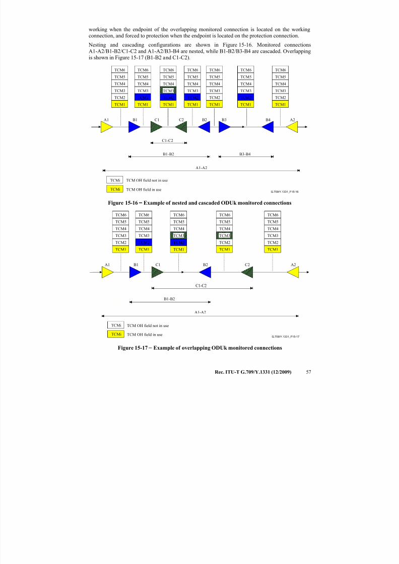
7/16/2019 G-709 ITU_T
http://slidepdf.com/reader/full/g-709-itut 65/218
Rec. ITU-T G.709/Y.1331 (12/2009) 57
working when the endpoint of the overlapping monitored connection is located on the working
connection, and forced to protection when the endpoint is located on the protection connection.
Nesting and cascading configurations are shown in Figure 15-16. Monitored connections
A1-A2/B1-B2/C1-C2 and A1-A2/B3-B4 are nested, while B1-B2/B3-B4 are cascaded. Overlapping
is shown in Figure 15-17 (B1-B2 and C1-C2).
G.709/Y.1331_F15-16
TCM OH field not in use
TCM OH field in use
A1 B1 C1 C2 B2 B3 B4 A2
A1-A2
B1-B2
C1-C2
B3-B4
TCM1 TCM1
TCM2
TCM1
TCM2
TCM3
TCM1
TCM2
TCM1 TCM1
TCM2
TCM1
TCM2
TCM3
TCM4
TCM5
TCM6
TCMi
TCMi
TCM2
TCM3
TCM4
TCM5
TCM6
TCM2
TCM3
TCM4
TCM6
TCM3
TCM4
TCM5
TCM6
TCM3
TCM4
TCM5
TCM6
TCM3
TCM4
TCM5
TCM6
TCM4
TCM5
TCM6
TCM5
Figure 15-16−
Example of nested and cascaded ODUk monitored connections
G.709/Y.1331_F15-17
TCM OH field not in use
TCM OH field in use
A1 B1 C1 C2B2 A2
A1-A2
B1-B2
C1-C2
TCM1 TCM1
TCM2
TCM1
TCM2
TCM1 TCM1
TCM2
TCM3
TCM4
TCM5
TCM6
TCMi
TCMi
TCM2
TCM3
TCM4
TCM5
TCM6
TCM2
TCM3
TCM4
TCM6
TCM3
TCM4
TCM5
TCM6
TCM3
TCM4
TCM5
TCM6
TCM5
Figure 15-17 − Example of overlapping ODUk monitored connections
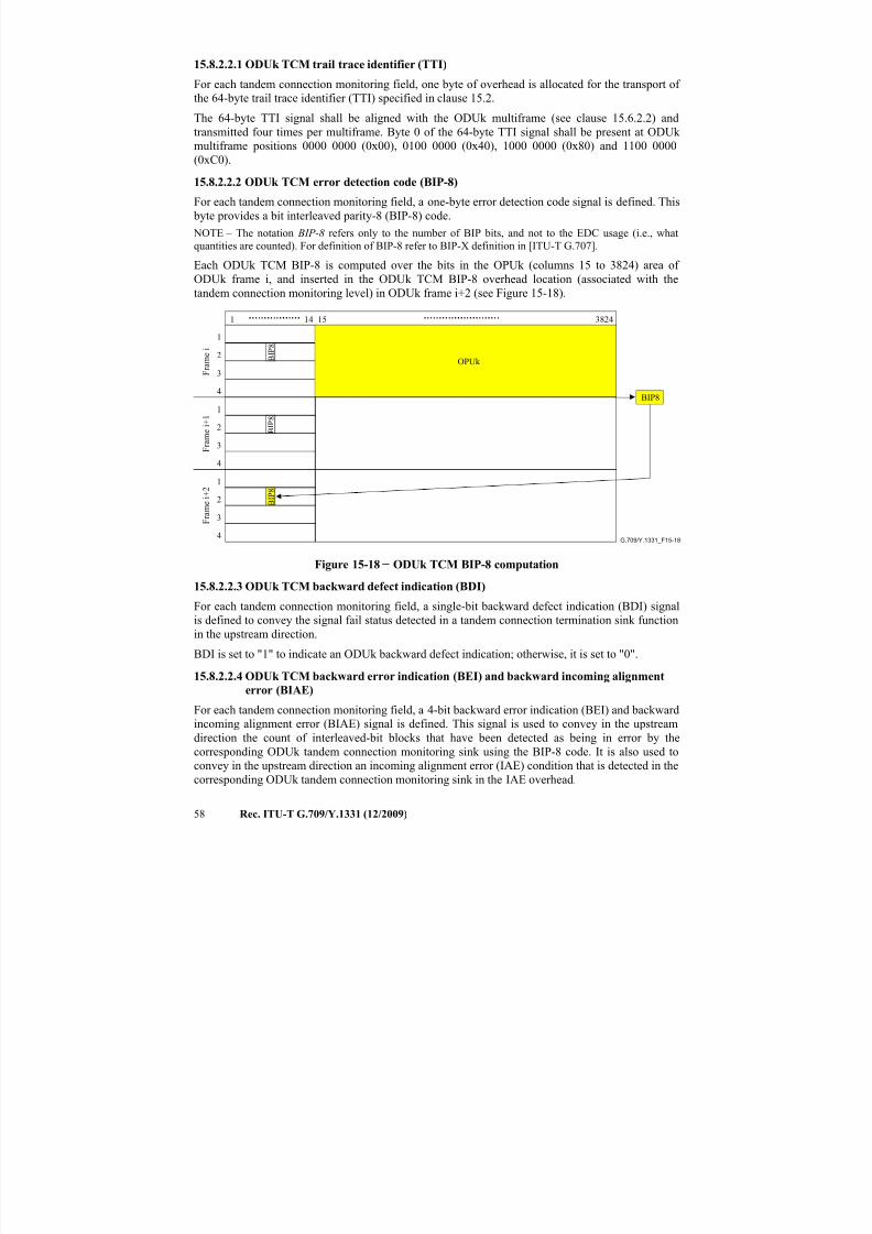
7/16/2019 G-709 ITU_T
http://slidepdf.com/reader/full/g-709-itut 66/218
58 Rec. ITU-T G.709/Y.1331 (12/2009)
15.8.2.2.1 ODUk TCM trail trace identifier (TTI)
For each tandem connection monitoring field, one byte of overhead is allocated for the transport of
the 64-byte trail trace identifier (TTI) specified in clause 15.2.
The 64-byte TTI signal shall be aligned with the ODUk multiframe (see clause 15.6.2.2) and
transmitted four times per multiframe. Byte 0 of the 64-byte TTI signal shall be present at ODUk
multiframe positions 0000 0000 (0x00), 0100 0000 (0x40), 1000 0000 (0x80) and 1100 0000(0xC0).
15.8.2.2.2 ODUk TCM error detection code (BIP-8)
For each tandem connection monitoring field, a one-byte error detection code signal is defined. This
byte provides a bit interleaved parity-8 (BIP-8) code.
NOTE – The notation BIP-8 refers only to the number of BIP bits, and not to the EDC usage (i.e., what
quantities are counted). For definition of BIP-8 refer to BIP-X definition in [ITU-T G.707].
Each ODUk TCM BIP-8 is computed over the bits in the OPUk (columns 15 to 3824) area of
ODUk frame i, and inserted in the ODUk TCM BIP-8 overhead location (associated with the
tandem connection monitoring level) in ODUk frame i+2 (see Figure 15-18).
G.709/Y.1331_F15-18
F r a m e i
F
r a m e i + 1
F r a m e i + 2
1
2
3
4
1 14 15 3824
1
2
3
4
BIP8
B I P 8
OPUk
1
2
3
4
B I P 8
B I P 8
Figure 15-18 − ODUk TCM BIP-8 computation
15.8.2.2.3 ODUk TCM backward defect indication (BDI)
For each tandem connection monitoring field, a single-bit backward defect indication (BDI) signal
is defined to convey the signal fail status detected in a tandem connection termination sink function
in the upstream direction.
BDI is set to "1" to indicate an ODUk backward defect indication; otherwise, it is set to "0".
15.8.2.2.4 ODUk TCM backward error indication (BEI) and backward incoming alignment
error (BIAE)
For each tandem connection monitoring field, a 4-bit backward error indication (BEI) and backward
incoming alignment error (BIAE) signal is defined. This signal is used to convey in the upstream
direction the count of interleaved-bit blocks that have been detected as being in error by the
corresponding ODUk tandem connection monitoring sink using the BIP-8 code. It is also used toconvey in the upstream direction an incoming alignment error (IAE) condition that is detected in the
corresponding ODUk tandem connection monitoring sink in the IAE overhead.
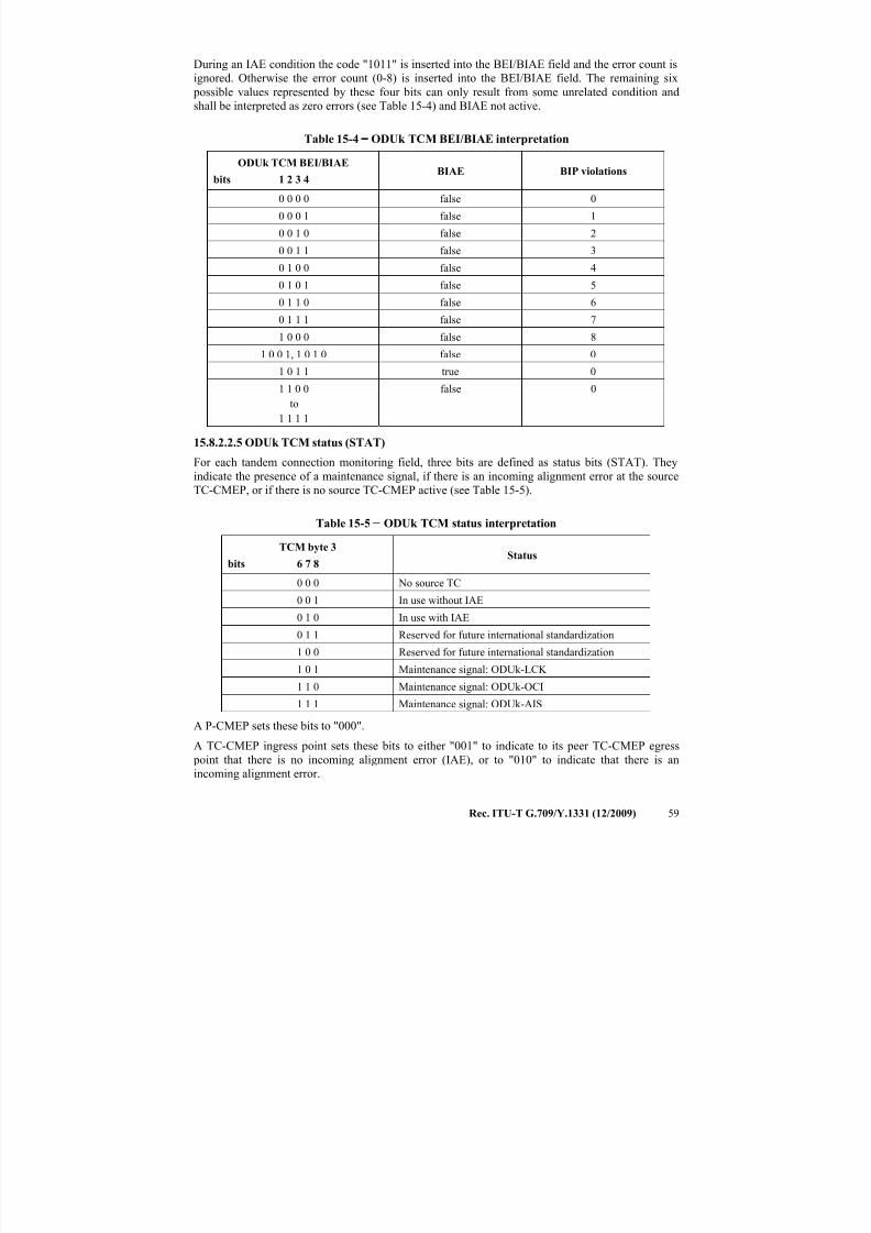
7/16/2019 G-709 ITU_T
http://slidepdf.com/reader/full/g-709-itut 67/218
Rec. ITU-T G.709/Y.1331 (12/2009) 59
During an IAE condition the code "1011" is inserted into the BEI/BIAE field and the error count is
ignored. Otherwise the error count (0-8) is inserted into the BEI/BIAE field. The remaining six
possible values represented by these four bits can only result from some unrelated condition and
shall be interpreted as zero errors (see Table 15-4) and BIAE not active.
Table 15-4 − ODUk TCM BEI/BIAE interpretation
ODUk TCM BEI/BIAE
bits 1 2 3 4BIAE BIP violations
0 0 0 0 false 0
0 0 0 1 false 1
0 0 1 0 false 2
0 0 1 1 false 3
0 1 0 0 false 4
0 1 0 1 false 5
0 1 1 0 false 6
0 1 1 1 false 7
1 0 0 0 false 8
1 0 0 1, 1 0 1 0 false 0
1 0 1 1 true 0
1 1 0 0
to
1 1 1 1
false 0
15.8.2.2.5 ODUk TCM status (STAT)
For each tandem connection monitoring field, three bits are defined as status bits (STAT). They
indicate the presence of a maintenance signal, if there is an incoming alignment error at the source
TC-CMEP, or if there is no source TC-CMEP active (see Table 15-5).
Table 15-5 − ODUk TCM status interpretation
TCM byte 3
bits 6 7 8Status
0 0 0 No source TC
0 0 1 In use without IAE
0 1 0 In use with IAE
0 1 1 Reserved for future international standardization
1 0 0 Reserved for future international standardization
1 0 1 Maintenance signal: ODUk-LCK
1 1 0 Maintenance signal: ODUk-OCI
1 1 1 Maintenance signal: ODUk-AIS
A P-CMEP sets these bits to "000".
A TC-CMEP ingress point sets these bits to either "001" to indicate to its peer TC-CMEP egress point that there is no incoming alignment error (IAE), or to "010" to indicate that there is an
incoming alignment error.
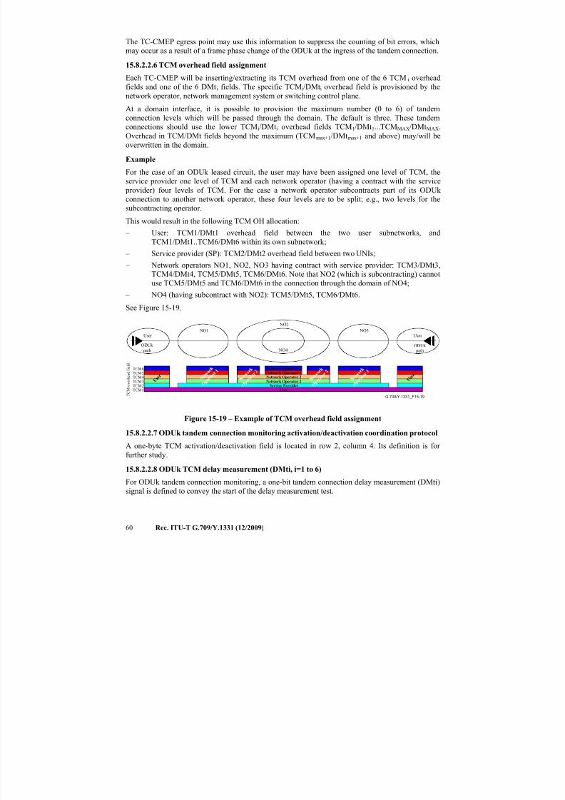
7/16/2019 G-709 ITU_T
http://slidepdf.com/reader/full/g-709-itut 68/218
60 Rec. ITU-T G.709/Y.1331 (12/2009)
The TC-CMEP egress point may use this information to suppress the counting of bit errors, which
may occur as a result of a frame phase change of the ODUk at the ingress of the tandem connection.
15.8.2.2.6 TCM overhead field assignment
Each TC-CMEP will be inserting/extracting its TCM overhead from one of the 6 TCM i overhead
fields and one of the 6 DMti fields. The specific TCMi/DMti overhead field is provisioned by the
network operator, network management system or switching control plane.At a domain interface, it is possible to provision the maximum number (0 to 6) of tandem
connection levels which will be passed through the domain. The default is three. These tandem
connections should use the lower TCMi/DMti overhead fields TCM1/DMt1...TCMMAX/DMtMAX.
Overhead in TCM/DMt fields beyond the maximum (TCMmax+1/DMtmax+1 and above) may/will be
overwritten in the domain.
Example
For the case of an ODUk leased circuit, the user may have been assigned one level of TCM, the
service provider one level of TCM and each network operator (having a contract with the service
provider) four levels of TCM. For the case a network operator subcontracts part of its ODUk connection to another network operator, these four levels are to be split; e.g., two levels for the
subcontracting operator.
This would result in the following TCM OH allocation:
– User: TCM1/DMt1 overhead field between the two user subnetworks, and
TCM1/DMt1..TCM6/DMt6 within its own subnetwork;
– Service provider (SP): TCM2/DMt2 overhead field between two UNIs;
– Network operators NO1, NO2, NO3 having contract with service provider: TCM3/DMt3,
TCM4/DMt4, TCM5/DMt5, TCM6/DMt6. Note that NO2 (which is subcontracting) cannot
use TCM5/DMt5 and TCM6/DMt6 in the connection through the domain of NO4;
– NO4 (having subcontract with NO2): TCM5/DMt5, TCM6/DMt6.
See Figure 15-19.
G.709/Y.1331_F15-19
User User NO1
NO2
NO3
NO4
Service ProviderUser
Network Operator 2Network Operator 2Network Operator 4Network Operator 4
T C M o v e r h e a d f i e l d
ODUk
pathODUk path
TCM1TCM2TCM3TCM4TCM5TCM6
Figure 15-19 – Example of TCM overhead field assignment
15.8.2.2.7 ODUk tandem connection monitoring activation/deactivation coordination protocol
A one-byte TCM activation/deactivation field is located in row 2, column 4. Its definition is for
further study.
15.8.2.2.8 ODUk TCM delay measurement (DMti, i=1 to 6)
For ODUk tandem connection monitoring, a one-bit tandem connection delay measurement (DMti)signal is defined to convey the start of the delay measurement test.
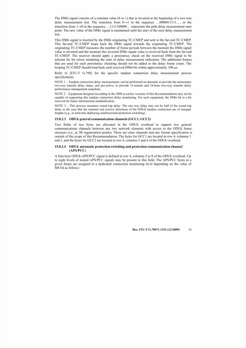
7/16/2019 G-709 ITU_T
http://slidepdf.com/reader/full/g-709-itut 69/218
Rec. ITU-T G.709/Y.1331 (12/2009) 61
The DMti signal consists of a constant value (0 or 1) that is inverted at the beginning of a two-way
delay measurement test. The transition from 0→1 in the sequence …0000011111…, or the
transition from 1→0 in the sequence …1111100000… represents the path delay measurement start
point. The new value of the DMti signal is maintained until the start of the next delay measurement
test.
This DMti signal is inserted by the DMti originating TC-CMEP and sent to the far-end TC-CMEP.
This far-end TC-CMEP loops back the DMti signal towards the originating TC-CMEP. The
originating TC-CMEP measures the number of frame periods between the moment the DMti signal
value is inverted and the moment this inverted DMti signal value is received back from the far-end
TC-CMEP. The receiver should apply a persistency check on the received DMti signal to be
tolerant for bit errors emulating the start of delay measurement indication. The additional frames
that are used for such persistency checking should not be added to the delay frame count. The
looping TC-CMEP should loop back each received DMti bit within approximately 100 µs.
Refer to [ITU-T G.798] for the specific tandem connection delay measurement process
specifications.
NOTE 1 – Tandem connection delay measurements can be performed on-demand, to provide the momentary
two-way transfer delay status, and pro-active, to provide 15-minute and 24-hour two-way transfer delay performance management snapshots.
NOTE 2 – Equipment designed according to the 2008 or earlier versions of this Recommendation may not be
capable of supporting this tandem connection delay monitoring. For such equipment, the DMti bit is a bit
reserved for future international standardization.
NOTE 3 – This process measures round trip delay. The one way delay may not be half of the round trip
delay in the case that the transmit and receive directions of the ODUk tandem connection are of unequal
lengths (e.g., in networks deploying unidirectional protection switching).
15.8.2.3 ODUk general communication channels (GCC1, GCC2)
Two fields of two bytes are allocated in the ODUk overhead to support two general
communications channels between any two network elements with access to the ODUk frame
structure (i.e., at 3R regeneration points). These are clear channels and any format specification is
outside of the scope of this Recommendation. The bytes for GCC1 are located in row 4, columns 1
and 2, and the bytes for GCC2 are located in row 4, columns 3 and 4 of the ODUk overhead.
15.8.2.4 ODUk automatic protection switching and protection communication channel
(APS/PCC)
A four-byte ODUk-APS/PCC signal is defined in row 4, columns 5 to 8 of the ODUk overhead. Up
to eight levels of nested APS/PCC signals may be present in this field. The APS/PCC bytes in a
given frame are assigned to a dedicated connection monitoring level depending on the value of
MFAS as follows:
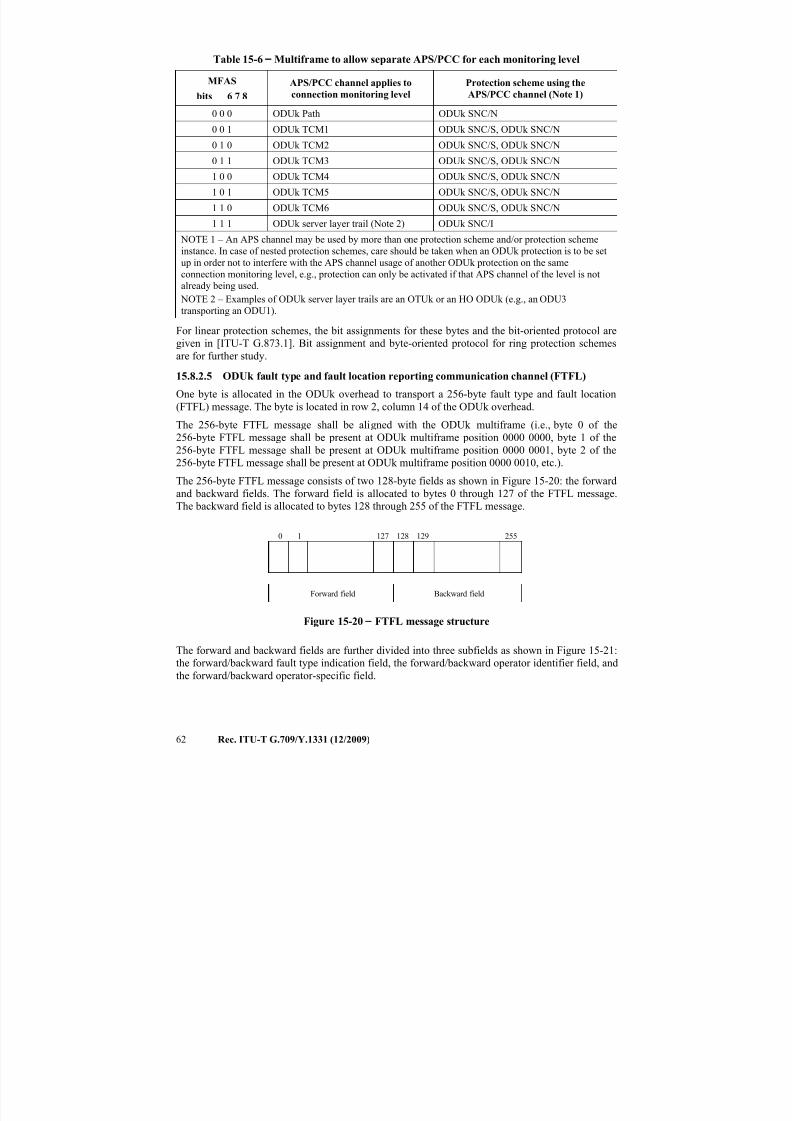
7/16/2019 G-709 ITU_T
http://slidepdf.com/reader/full/g-709-itut 70/218
62 Rec. ITU-T G.709/Y.1331 (12/2009)
Table 15-6 − Multiframe to allow separate APS/PCC for each monitoring level
MFAS
bits 6 7 8
APS/PCC channel applies to
connection monitoring level
Protection scheme using the
APS/PCC channel (Note 1)
0 0 0 ODUk Path ODUk SNC/N
0 0 1 ODUk TCM1 ODUk SNC/S, ODUk SNC/N
0 1 0 ODUk TCM2 ODUk SNC/S, ODUk SNC/N
0 1 1 ODUk TCM3 ODUk SNC/S, ODUk SNC/N
1 0 0 ODUk TCM4 ODUk SNC/S, ODUk SNC/N
1 0 1 ODUk TCM5 ODUk SNC/S, ODUk SNC/N
1 1 0 ODUk TCM6 ODUk SNC/S, ODUk SNC/N
1 1 1 ODUk server layer trail (Note 2) ODUk SNC/I
NOTE 1 – An APS channel may be used by more than one protection scheme and/or protection scheme
instance. In case of nested protection schemes, care should be taken when an ODUk protection is to be set
up in order not to interfere with the APS channel usage of another ODUk protection on the same
connection monitoring level, e.g., protection can only be activated if that APS channel of the level is notalready being used.
NOTE 2 – Examples of ODUk server layer trails are an OTUk or an HO ODUk (e.g., an ODU3
transporting an ODU1).
For linear protection schemes, the bit assignments for these bytes and the bit-oriented protocol are
given in [ITU-T G.873.1]. Bit assignment and byte-oriented protocol for ring protection schemes
are for further study.
15.8.2.5 ODUk fault type and fault location reporting communication channel (FTFL)
One byte is allocated in the ODUk overhead to transport a 256-byte fault type and fault location
(FTFL) message. The byte is located in row 2, column 14 of the ODUk overhead.The 256-byte FTFL message shall be aligned with the ODUk multiframe (i.e., byte 0 of the
256-byte FTFL message shall be present at ODUk multiframe position 0000 0000, byte 1 of the
256-byte FTFL message shall be present at ODUk multiframe position 0000 0001, byte 2 of the
256-byte FTFL message shall be present at ODUk multiframe position 0000 0010, etc.).
The 256-byte FTFL message consists of two 128-byte fields as shown in Figure 15-20: the forward
and backward fields. The forward field is allocated to bytes 0 through 127 of the FTFL message.
The backward field is allocated to bytes 128 through 255 of the FTFL message.
0 1 127 128 129 255
Forward field Backward field
Figure 15-20 − FTFL message structure
The forward and backward fields are further divided into three subfields as shown in Figure 15-21:
the forward/backward fault type indication field, the forward/backward operator identifier field, and
the forward/backward operator-specific field.
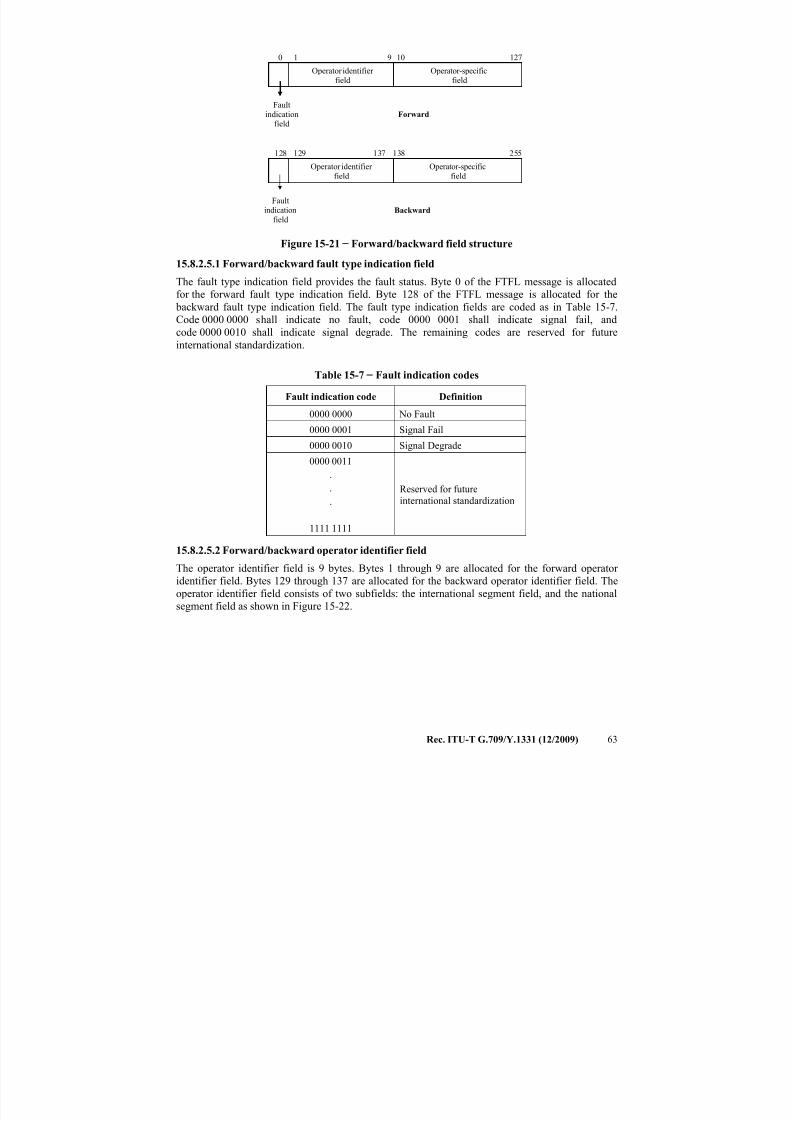
7/16/2019 G-709 ITU_T
http://slidepdf.com/reader/full/g-709-itut 71/218
Rec. ITU-T G.709/Y.1331 (12/2009) 63
0 1 9 10 127
Operator identifier field
Operator-specificfield
Faultindication
fieldForward
128 129 137 138 255
Operator identifier field
Operator-specificfield
Faultindication
fieldBackward
Figure 15-21 − Forward/backward field structure
15.8.2.5.1 Forward/backward fault type indication field
The fault type indication field provides the fault status. Byte 0 of the FTFL message is allocated
for the forward fault type indication field. Byte 128 of the FTFL message is allocated for the
backward fault type indication field. The fault type indication fields are coded as in Table 15-7.
Code 0000 0000 shall indicate no fault, code 0000 0001 shall indicate signal fail, and
code 0000 0010 shall indicate signal degrade. The remaining codes are reserved for future
international standardization.
Table 15-7 − Fault indication codes
Fault indication code Definition
0000 0000 No Fault
0000 0001 Signal Fail
0000 0010 Signal Degrade
0000 0011
.
.
.
1111 1111
Reserved for future
international standardization
15.8.2.5.2 Forward/backward operator identifier field
The operator identifier field is 9 bytes. Bytes 1 through 9 are allocated for the forward operator
identifier field. Bytes 129 through 137 are allocated for the backward operator identifier field. The
operator identifier field consists of two subfields: the international segment field, and the national
segment field as shown in Figure 15-22.
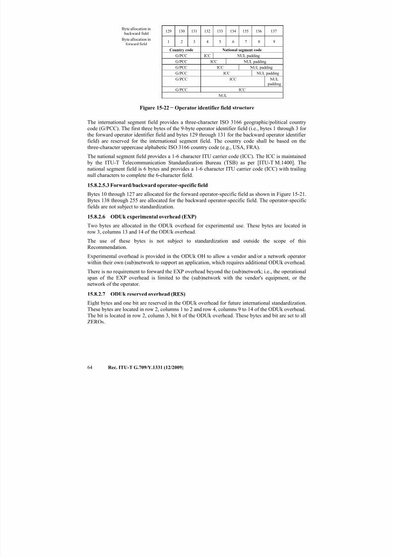
7/16/2019 G-709 ITU_T
http://slidepdf.com/reader/full/g-709-itut 72/218
64 Rec. ITU-T G.709/Y.1331 (12/2009)
Byte allocation in backward field
129 130 131 132 133 134 135 136 137
Byte allocation inforward field
1 2 3 4 5 6 7 8 9
Country code National segment code
G/PCC ICC NUL padding
G/PCC ICC NUL padding
G/PCC ICC NUL paddingG/PCC ICC NUL padding
G/PCC ICC NUL
padding
G/PCC ICC
NUL
Figure 15-22 − Operator identifier field structure
The international segment field provides a three-character ISO 3166 geographic/political country
code (G/PCC). The first three bytes of the 9-byte operator identifier field (i.e., bytes 1 through 3 for
the forward operator identifier field and bytes 129 through 131 for the backward operator identifier field) are reserved for the international segment field. The country code shall be based on the
three-character uppercase alphabetic ISO 3166 country code (e.g., USA, FRA).
The national segment field provides a 1-6 character ITU carrier code (ICC). The ICC is maintained
by the ITU-T Telecommunication Standardization Bureau (TSB) as per [ITU-T M.1400]. The
national segment field is 6 bytes and provides a 1-6 character ITU carrier code (ICC) with trailing
null characters to complete the 6-character field.
15.8.2.5.3 Forward/backward operator-specific field
Bytes 10 through 127 are allocated for the forward operator-specific field as shown in Figure 15-21.
Bytes 138 through 255 are allocated for the backward operator-specific field. The operator-specificfields are not subject to standardization.
15.8.2.6 ODUk experimental overhead (EXP)
Two bytes are allocated in the ODUk overhead for experimental use. These bytes are located in
row 3, columns 13 and 14 of the ODUk overhead.
The use of these bytes is not subject to standardization and outside the scope of this
Recommendation.
Experimental overhead is provided in the ODUk OH to allow a vendor and/or a network operator
within their own (sub)network to support an application, which requires additional ODUk overhead.
There is no requirement to forward the EXP overhead beyond the (sub)network; i.e., the operationalspan of the EXP overhead is limited to the (sub)network with the vendor's equipment, or the
network of the operator.
15.8.2.7 ODUk reserved overhead (RES)
Eight bytes and one bit are reserved in the ODUk overhead for future international standardization.
These bytes are located in row 2, columns 1 to 2 and row 4, columns 9 to 14 of the ODUk overhead.
The bit is located in row 2, column 3, bit 8 of the ODUk overhead. These bytes and bit are set to all
ZEROs.
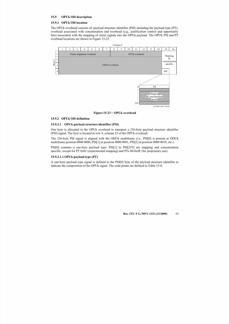
7/16/2019 G-709 ITU_T
http://slidepdf.com/reader/full/g-709-itut 73/218
Rec. ITU-T G.709/Y.1331 (12/2009) 65
15.9 OPUk OH description
15.9.1 OPUk OH location
The OPUk overhead consists of: payload structure identifier (PSI) including the payload type (PT),
overhead associated with concatenation and overhead (e.g., justification control and opportunity
bits) associated with the mapping of client signals into the OPUk payload. The OPUk PSI and PT
overhead locations are shown in Figure 15-23.
G.709/Y.1331_F15-23
Column #
R o w #
ODUk overhead
OTUk overheadFrame alignment overheadMapping
&
concatenation
specific
1
2
3
4 PSI
1 2 3 4 5 6 7 8 9 10 11 12 13 14 15 16
255
0
1
PT
Mapping
& concatenation
specific
Figure 15-23 − OPUk overhead
15.9.2 OPUk OH definition
15.9.2.1 OPUk payload structure identifier (PSI)
One byte is allocated in the OPUk overhead to transport a 256-byte payload structure identifier
(PSI) signal. The byte is located in row 4, column 15 of the OPUk overhead.
The 256-byte PSI signal is aligned with the ODUk multiframe (i.e., PSI[0] is present at ODUk
multiframe position 0000 0000, PSI[1] at position 0000 0001, PSI[2] at position 0000 0010, etc.).
PSI[0] contains a one-byte payload type. PSI[1] to PSI[255] are mapping and concatenation
specific, except for PT 0x01 (experimental mapping) and PTs 80-0x8F (for proprietary use).
15.9.2.1.1 OPUk payload type (PT)A one-byte payload type signal is defined in the PSI[0] byte of the payload structure identifier to
indicate the composition of the OPUk signal. The code points are defined in Table 15-8.
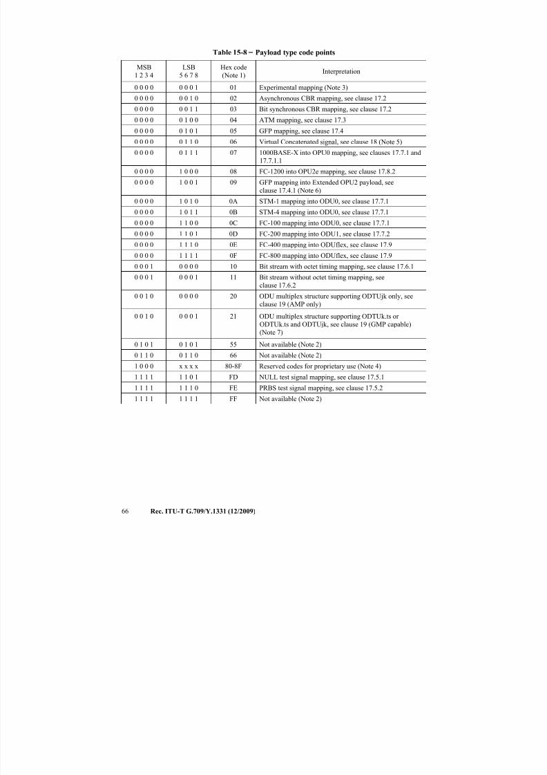
7/16/2019 G-709 ITU_T
http://slidepdf.com/reader/full/g-709-itut 74/218
66 Rec. ITU-T G.709/Y.1331 (12/2009)
Table 15-8 − Payload type code points
MSB
1 2 3 4
LSB
5 6 7 8
Hex code
(Note 1)Interpretation
0 0 0 0 0 0 0 1 01 Experimental mapping (Note 3)
0 0 0 0 0 0 1 0 02 Asynchronous CBR mapping, see clause 17.2
0 0 0 0 0 0 1 1 03 Bit synchronous CBR mapping, see clause 17.2
0 0 0 0 0 1 0 0 04 ATM mapping, see clause 17.3
0 0 0 0 0 1 0 1 05 GFP mapping, see clause 17.4
0 0 0 0 0 1 1 0 06 Virtual Concatenated signal, see clause 18 (Note 5)
0 0 0 0 0 1 1 1 07 1000BASE-X into OPU0 mapping, see clauses 17.7.1 and
17.7.1.1
0 0 0 0 1 0 0 0 08 FC-1200 into OPU2e mapping, see clause 17.8.2
0 0 0 0 1 0 0 1 09 GFP mapping into Extended OPU2 payload, see
clause 17.4.1 (Note 6)
0 0 0 0 1 0 1 0 0A STM-1 mapping into ODU0, see clause 17.7.1
0 0 0 0 1 0 1 1 0B STM-4 mapping into ODU0, see clause 17.7.1
0 0 0 0 1 1 0 0 0C FC-100 mapping into ODU0, see clause 17.7.1
0 0 0 0 1 1 0 1 0D FC-200 mapping into ODU1, see clause 17.7.2
0 0 0 0 1 1 1 0 0E FC-400 mapping into ODUflex, see clause 17.9
0 0 0 0 1 1 1 1 0F FC-800 mapping into ODUflex, see clause 17.9
0 0 0 1 0 0 0 0 10 Bit stream with octet timing mapping, see clause 17.6.1
0 0 0 1 0 0 0 1 11 Bit stream without octet timing mapping, see
clause 17.6.2
0 0 1 0 0 0 0 0 20 ODU multiplex structure supporting ODTUjk only, see
clause 19 (AMP only)
0 0 1 0 0 0 0 1 21 ODU multiplex structure supporting ODTUk.ts or
ODTUk.ts and ODTUjk, see clause 19 (GMP capable)
(Note 7)
0 1 0 1 0 1 0 1 55 Not available (Note 2)
0 1 1 0 0 1 1 0 66 Not available (Note 2)
1 0 0 0 x x x x 80-8F Reserved codes for proprietary use (Note 4)
1 1 1 1 1 1 0 1 FD NULL test signal mapping, see clause 17.5.1
1 1 1 1 1 1 1 0 FE PRBS test signal mapping, see clause 17.5.2
1 1 1 1 1 1 1 1 FF Not available (Note 2)
7/16/2019 G-709 ITU_T
http://slidepdf.com/reader/full/g-709-itut 75/218
Rec. ITU-T G.709/Y.1331 (12/2009) 67
Table 15-8 − Payload type code points
NOTE 1 – There are 216 spare codes left for future international standardization. Refer to Annex A of
[ITU-T G.806] for the procedure to obtain one of these codes for a new payload type.
NOTE 2 – These values are excluded from the set of available code points. These bit patterns are present
in ODUk maintenance signals. NOTE 3 – Value "01" is only to be used for experimental activities in cases where a mapping code is not
defined in this table. Refer to Annex A of [ITU-T G.806] for more information on the use of this code.
NOTE 4 – These 16 code values will not be subject to further standardization. Refer to Annex A of
[ITU-T G.806] for more information on the use of these codes.
NOTE 5 – For the payload type of the virtual concatenated signal a dedicated payload type overhead
(vcPT) is used, see clause 18.
NOTE 6 – Supplement 43 (02/2008) to the ITU-T G-series of Recommendations indicated that this
mapping recommended using Payload Type 87.
NOTE 7 – Equipment supporting ODTUk.ts for OPU2 or OPU3 must be backward compatible with
equipment which supports only the ODTUjk. ODTUk.ts capable equipment transmitting PT=21 which
receives PT=20 from the far end shall revert to PT=20 and operate in ODTUjk only mode. Refer to[ITU-T G.798] for the specification.
15.9.2.2 OPUk mapping specific overhead
Seven bytes are reserved in the OPUk overhead for mapping and concatenation specific overhead.
These bytes are located in rows 1 to 3, columns 15 and 16 and column 16 row 4. In addition,
255 bytes in the PSI are reserved for mapping and concatenation specific purposes.
The use of these bytes depends on the specific client signal mapping (defined in clauses 17 and 19)
and the use of concatenation (see clause 18).
16 Maintenance signalsAn alarm indication signal (AIS) is a signal sent downstream as an indication that an upstream
defect has been detected. An AIS signal is generated in an adaptation sink function. An AIS signal
is detected in a trail termination sink function to suppress defects or failures that would otherwise be
detected as a consequence of the interruption of the transport of the original signal at an upstream
point.
A forward defect indication (FDI) is a signal sent downstream as an indication that an upstream
defect has been detected. An FDI signal is generated in an adaptation sink function. An FDI signal
is detected in a trail termination sink function to suppress defects or failures that would otherwise be
detected as a consequence of the interruption of the transport of the original signal at an upstream
point. NOTE – AIS and FDI are similar signals. AIS is used as the term when the signal is in the digital domain.
FDI is used as the term when the signal is in the optical domain; FDI is transported as non-associated
overhead in the OTM overhead signal (OOS).
An open connection indication (OCI) is a signal sent downstream as an indication that upstream the
signal is not connected to a trail termination source. An OCI signal is generated in a connection
function and output by this connection function on each of its output connection points, which are
not connected to one of its input connection points. An OCI signal is detected in a trail termination
sink function.
A locked (LCK) is a signal sent downstream as an indication that upstream the connection is
"locked", and no signal is passed through.
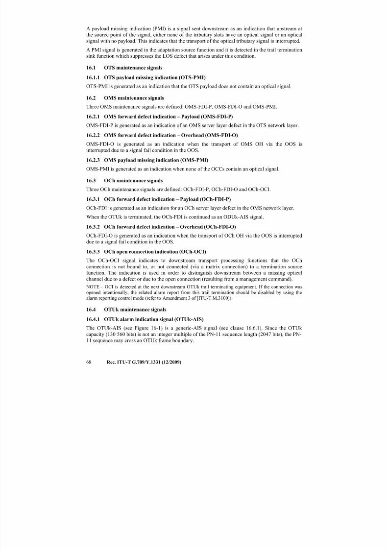
7/16/2019 G-709 ITU_T
http://slidepdf.com/reader/full/g-709-itut 76/218
68 Rec. ITU-T G.709/Y.1331 (12/2009)
A payload missing indication (PMI) is a signal sent downstream as an indication that upstream at
the source point of the signal, either none of the tributary slots have an optical signal or an optical
signal with no payload. This indicates that the transport of the optical tributary signal is interrupted.
A PMI signal is generated in the adaptation source function and it is detected in the trail termination
sink function which suppresses the LOS defect that arises under this condition.
16.1 OTS maintenance signals
16.1.1 OTS payload missing indication (OTS-PMI)
OTS-PMI is generated as an indication that the OTS payload does not contain an optical signal.
16.2 OMS maintenance signals
Three OMS maintenance signals are defined: OMS-FDI-P, OMS-FDI-O and OMS-PMI.
16.2.1 OMS forward defect indication – Payload (OMS-FDI-P)
OMS-FDI-P is generated as an indication of an OMS server layer defect in the OTS network layer.
16.2.2 OMS forward defect indication – Overhead (OMS-FDI-O)
OMS-FDI-O is generated as an indication when the transport of OMS OH via the OOS is
interrupted due to a signal fail condition in the OOS.
16.2.3 OMS payload missing indication (OMS-PMI)
OMS-PMI is generated as an indication when none of the OCCs contain an optical signal.
16.3 OCh maintenance signals
Three OCh maintenance signals are defined: OCh-FDI-P, OCh-FDI-O and OCh-OCI.
16.3.1 OCh forward defect indication – Payload (OCh-FDI-P)
OCh-FDI is generated as an indication for an OCh server layer defect in the OMS network layer.
When the OTUk is terminated, the OCh-FDI is continued as an ODUk-AIS signal.
16.3.2 OCh forward defect indication – Overhead (OCh-FDI-O)
OCh-FDI-O is generated as an indication when the transport of OCh OH via the OOS is interrupted
due to a signal fail condition in the OOS.
16.3.3 OCh open connection indication (OCh-OCI)
The OCh-OCI signal indicates to downstream transport processing functions that the OCh
connection is not bound to, or not connected (via a matrix connection) to a termination sourcefunction. The indication is used in order to distinguish downstream between a missing optical
channel due to a defect or due to the open connection (resulting from a management command).
NOTE – OCI is detected at the next downstream OTUk trail terminating equipment. If the connection was
opened intentionally, the related alarm report from this trail termination should be disabled by using the
alarm reporting control mode (refer to Amendment 3 of [ITU-T M.3100]).
16.4 OTUk maintenance signals
16.4.1 OTUk alarm indication signal (OTUk-AIS)
The OTUk-AIS (see Figure 16-1) is a generic-AIS signal (see clause 16.6.1). Since the OTUk
capacity (130 560 bits) is not an integer multiple of the PN-11 sequence length (2047 bits), the PN-11 sequence may cross an OTUk frame boundary.
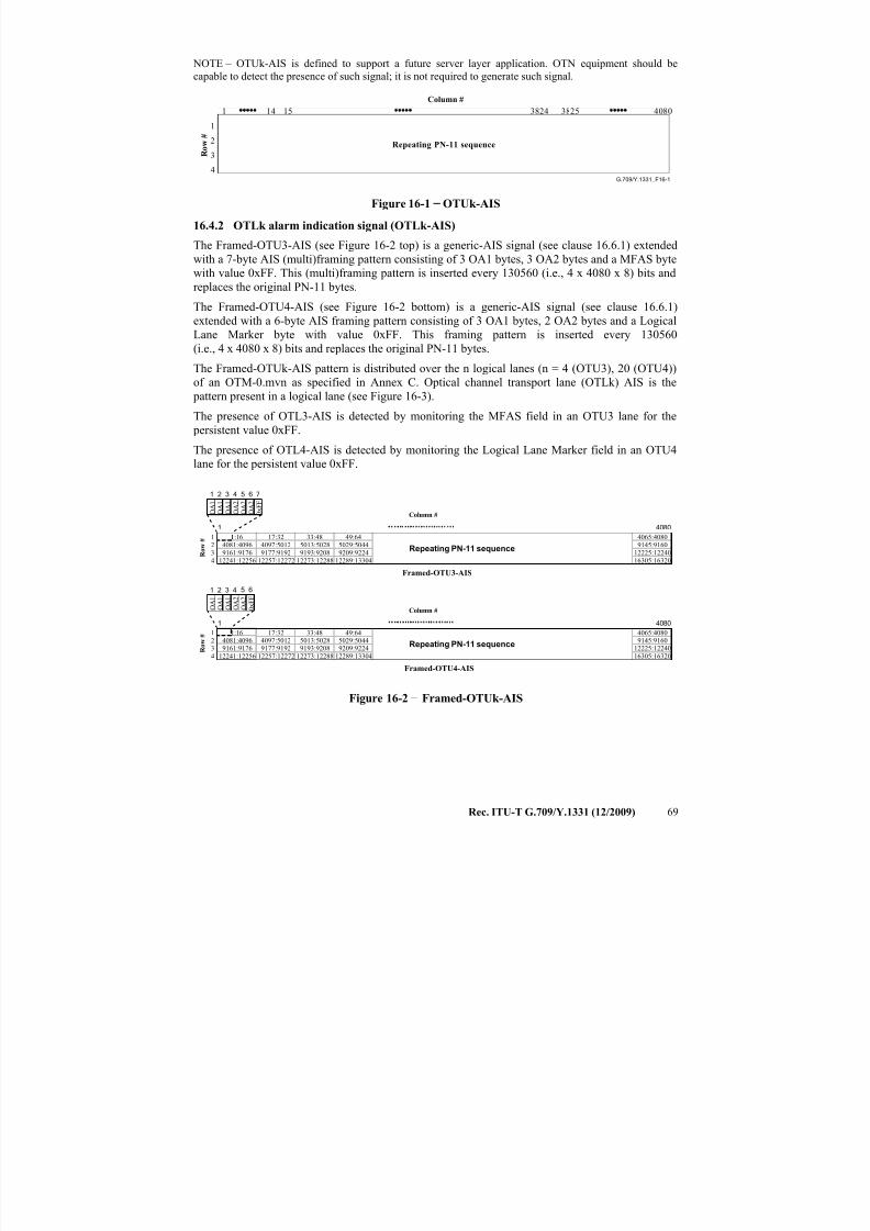
7/16/2019 G-709 ITU_T
http://slidepdf.com/reader/full/g-709-itut 77/218
Rec. ITU-T G.709/Y.1331 (12/2009) 69
NOTE – OTUk-AIS is defined to support a future server layer application. OTN equipment should be
capable to detect the presence of such signal; it is not required to generate such signal.
G.709/Y.1331_F16-1
Repeating PN-11 sequence
1
2
3
4
1 3824 3825 408014 15
R o
w
#
Column #
Figure 16-1 − OTUk-AIS
16.4.2 OTLk alarm indication signal (OTLk-AIS)
The Framed-OTU3-AIS (see Figure 16-2 top) is a generic-AIS signal (see clause 16.6.1) extended
with a 7-byte AIS (multi)framing pattern consisting of 3 OA1 bytes, 3 OA2 bytes and a MFAS byte
with value 0xFF. This (multi)framing pattern is inserted every 130560 (i.e., 4 x 4080 x 8) bits and
replaces the original PN-11 bytes.
The Framed-OTU4-AIS (see Figure 16-2 bottom) is a generic-AIS signal (see clause 16.6.1)
extended with a 6-byte AIS framing pattern consisting of 3 OA1 bytes, 2 OA2 bytes and a Logical
Lane Marker byte with value 0xFF. This framing pattern is inserted every 130560
(i.e., 4 x 4080 x 8) bits and replaces the original PN-11 bytes.
The Framed-OTUk-AIS pattern is distributed over the n logical lanes (n = 4 (OTU3), 20 (OTU4))
of an OTM-0.mvn as specified in Annex C. Optical channel transport lane (OTLk) AIS is the
pattern present in a logical lane (see Figure 16-3).
The presence of OTL3-AIS is detected by monitoring the MFAS field in an OTU3 lane for the
persistent value 0xFF.
The presence of OTL4-AIS is detected by monitoring the Logical Lane Marker field in an OTU4lane for the persistent value 0xFF.
1:16
12241:12256
9161:91764081:4096
12257:12272
9177:91924097:5012
17:32
12273:12288
9193:92085013:5028
33:48
12289:13304
9209:92245029:5044
49:64
1 4080
Column #
R o w
#
O A 1
O A 1
O A 1
O A 2
O A 2
O A 2
0 x F F
1 72 3 4 5 6
1 4080
Repeating PN-11 sequence
Column #
R o w
#
O A 1 O A 1 O A 1 O A 2 O A 2 0 x F F
1 2 3 4 5 6
Framed-OTU3-AIS
Framed-OTU4-AIS
4
321
16305:16320
12225:122409145:91604065:4080
1:16
12241:122569161:91764081:4096
12257:122729177:91924097:5012
17:32
12273:122889193:92085013:5028
33:48
12289:133049209:92245029:5044
49:64
Repeating PN-11 sequence
4321
16305:1632012225:122409145:91604065:4080
Figure 16-2 − Framed-OTUk-AIS
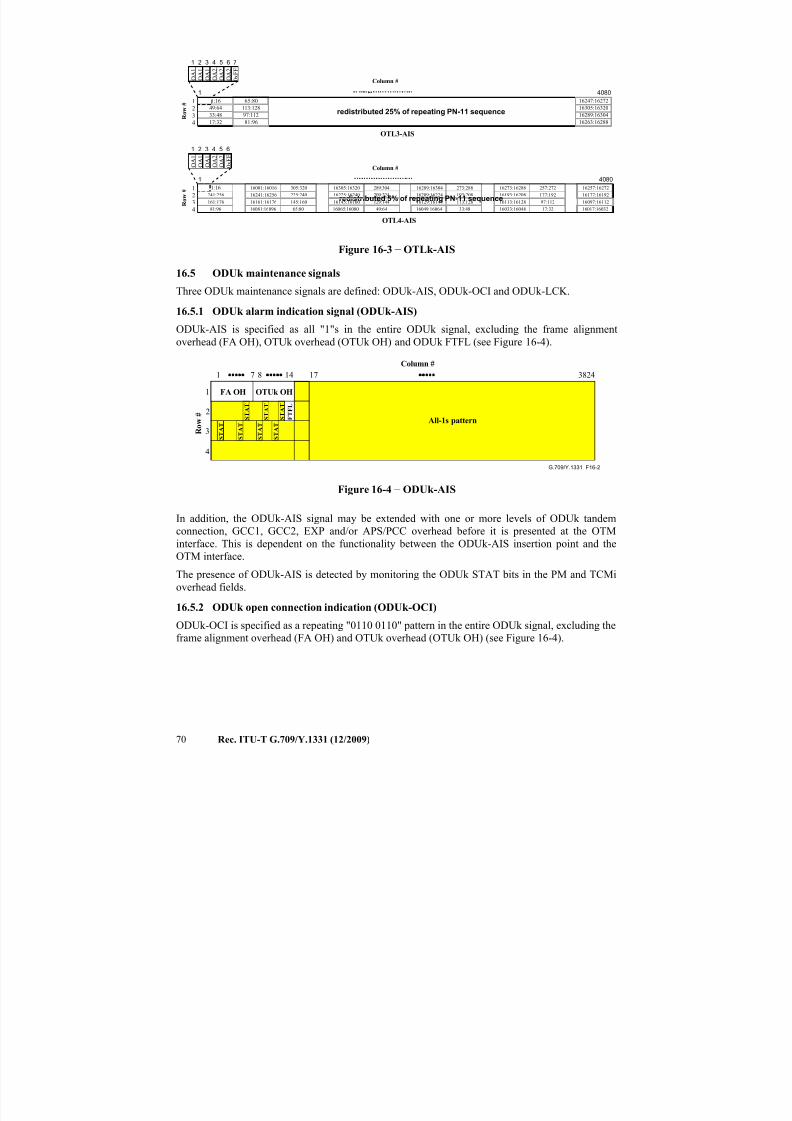
7/16/2019 G-709 ITU_T
http://slidepdf.com/reader/full/g-709-itut 78/218
70 Rec. ITU-T G.709/Y.1331 (12/2009)
16113:16128113:12816129:16144129:14416145:16160145:16016161:16176161:176
16177:16192177:19216193:16208193:20816209:16224209:22416241:16256241:256
81:96 16081:16096 65:80 16065:16080
16257:16272257:27216273:16288273:28816289:16304289:304
33:48 16017:1603217:3216033:16048
305:32016001:16016
65:80
49:64
33:48
17:32
1:16
1 4080
Column #
R o w
#
O A 1
O A 1
O A 1
O A 2
O A 2
O A 2
0 x F F
1 72 3 4 5 6
1 4080
redistributed 5% of repeating PN-11 sequence
Column #
R o w
#
O A 1
O A 1
O A 1
O A 2
O A 2
0 x F F
1 2 3 4 5 6
OTL3-AIS
OTL4-AIS
4321
1:16
redistributed 25% of repeating PN-11 sequence
43
21
16263:16288
16289:16304
16305:16320
16247:16272
81:96
97:112
113:128
49:64 16049:16064
16305:16320
16225:16240225:240
16097:1611297:112
Figure 16-3 − OTLk-AIS
16.5 ODUk maintenance signals
Three ODUk maintenance signals are defined: ODUk-AIS, ODUk-OCI and ODUk-LCK.
16.5.1 ODUk alarm indication signal (ODUk-AIS)
ODUk-AIS is specified as all "1"s in the entire ODUk signal, excluding the frame alignment
overhead (FA OH), OTUk overhead (OTUk OH) and ODUk FTFL (see Figure 16-4).
G.709/Y.1331_F16-2
3824
All-1s pattern
1
2
3
4
1 178 14
F T F L
FA OH OTUk OH
S T A T
S T A T
S T A T
S T A T
S T A T
S T A T
S T A T
7
R o w
#
Column #
Figure 16-4 − ODUk-AIS
In addition, the ODUk-AIS signal may be extended with one or more levels of ODUk tandem
connection, GCC1, GCC2, EXP and/or APS/PCC overhead before it is presented at the OTM
interface. This is dependent on the functionality between the ODUk-AIS insertion point and theOTM interface.
The presence of ODUk-AIS is detected by monitoring the ODUk STAT bits in the PM and TCMi
overhead fields.
16.5.2 ODUk open connection indication (ODUk-OCI)
ODUk-OCI is specified as a repeating "0110 0110" pattern in the entire ODUk signal, excluding the
frame alignment overhead (FA OH) and OTUk overhead (OTUk OH) (see Figure 16-4).
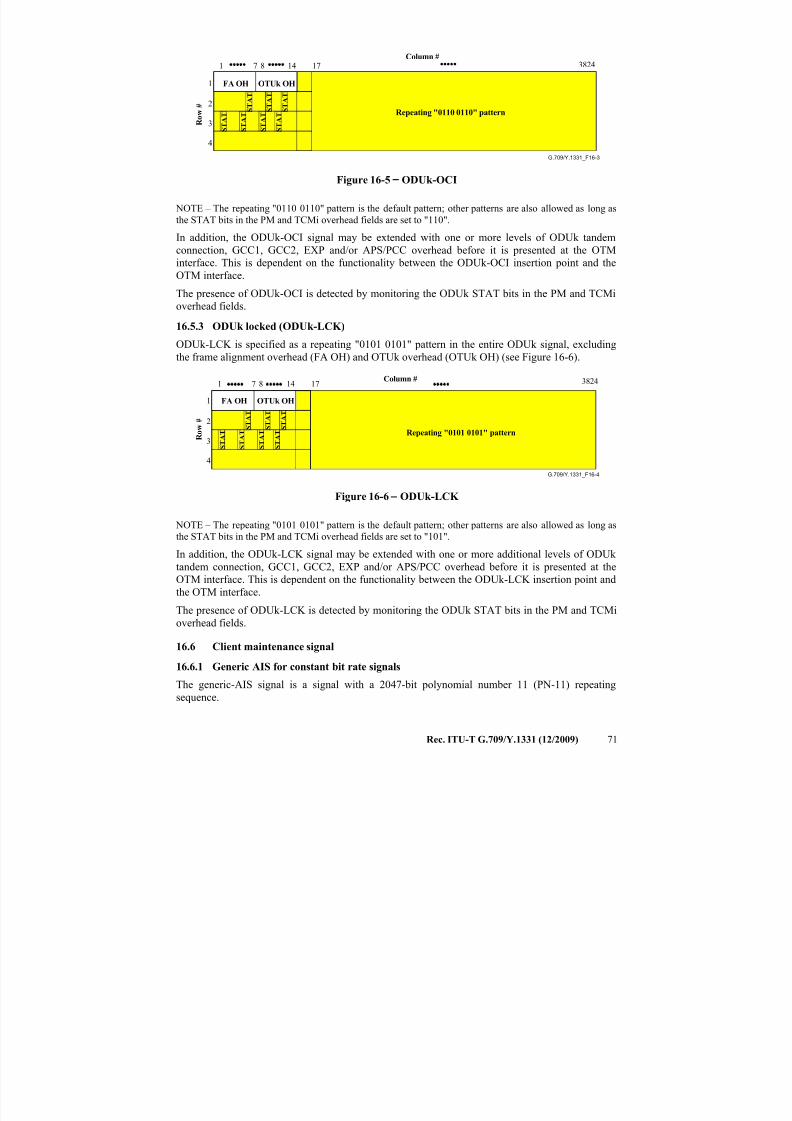
7/16/2019 G-709 ITU_T
http://slidepdf.com/reader/full/g-709-itut 79/218
Rec. ITU-T G.709/Y.1331 (12/2009) 71
G.709/Y.1331_F16-3
Repeating "0110 0110" pattern
1
2
3
4
1 17 38248 14
FA OH OTUk OH
S T A T
S T A T
S T A T
S T A T
S T A T
S T A T
S T A T
7
R o w
#
Column #
Figure 16-5 − ODUk-OCI
NOTE – The repeating "0110 0110" pattern is the default pattern; other patterns are also allowed as long as
the STAT bits in the PM and TCMi overhead fields are set to "110".
In addition, the ODUk-OCI signal may be extended with one or more levels of ODUk tandem
connection, GCC1, GCC2, EXP and/or APS/PCC overhead before it is presented at the OTM
interface. This is dependent on the functionality between the ODUk-OCI insertion point and the
OTM interface.
The presence of ODUk-OCI is detected by monitoring the ODUk STAT bits in the PM and TCMi
overhead fields.
16.5.3 ODUk locked (ODUk-LCK)
ODUk-LCK is specified as a repeating "0101 0101" pattern in the entire ODUk signal, excluding
the frame alignment overhead (FA OH) and OTUk overhead (OTUk OH) (see Figure 16-6).
G.709/Y.1331_F16-4
Repeating "0101 0101" pattern
1
2
3
4
1 17 38248 14
FA OH OTUk OH
S T A T
S T A T
S T A T
S T A T
S T A T
S T A T
S T A T
7
R o w
#
Column #
Figure 16-6 − ODUk-LCK
NOTE – The repeating "0101 0101" pattern is the default pattern; other patterns are also allowed as long as
the STAT bits in the PM and TCMi overhead fields are set to "101".
In addition, the ODUk-LCK signal may be extended with one or more additional levels of ODUk
tandem connection, GCC1, GCC2, EXP and/or APS/PCC overhead before it is presented at the
OTM interface. This is dependent on the functionality between the ODUk-LCK insertion point and
the OTM interface.
The presence of ODUk-LCK is detected by monitoring the ODUk STAT bits in the PM and TCMi
overhead fields.
16.6 Client maintenance signal
16.6.1 Generic AIS for constant bit rate signals
The generic-AIS signal is a signal with a 2047-bit polynomial number 11 (PN-11) repeating
sequence.
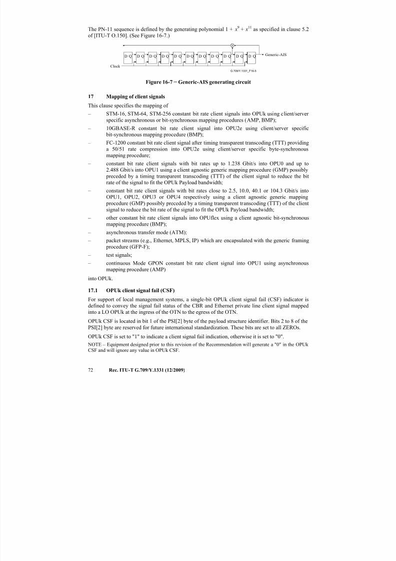
7/16/2019 G-709 ITU_T
http://slidepdf.com/reader/full/g-709-itut 80/218
72 Rec. ITU-T G.709/Y.1331 (12/2009)
The PN-11 sequence is defined by the generating polynomial 1 + x9 + x11 as specified in clause 5.2
of [ITU-T O.150]. (See Figure 16-7.)
G.709/Y.1331_F16-5
Generic-AIS
Clock
D Q D Q D Q D Q D Q D Q D Q D Q D Q D Q D Q
Figure 16-7 − Generic-AIS generating circuit
17 Mapping of client signals
This clause specifies the mapping of
– STM-16, STM-64, STM-256 constant bit rate client signals into OPUk using client/server
specific asynchronous or bit-synchronous mapping procedures (AMP, BMP);
– 10GBASE-R constant bit rate client signal into OPU2e using client/server specific
bit-synchronous mapping procedure (BMP); – FC-1200 constant bit rate client signal after timing transparent transcoding (TTT) providing
a 50/51 rate compression into OPU2e using client/server specific byte-synchronous
mapping procedure;
– constant bit rate client signals with bit rates up to 1.238 Gbit/s into OPU0 and up to
2.488 Gbit/s into OPU1 using a client agnostic generic mapping procedure (GMP) possibly
preceded by a timing transparent transcoding (TTT) of the client signal to reduce the bit
rate of the signal to fit the OPUk Payload bandwidth;
– constant bit rate client signals with bit rates close to 2.5, 10.0, 40.1 or 104.3 Gbit/s into
OPU1, OPU2, OPU3 or OPU4 respectively using a client agnostic generic mapping
procedure (GMP) possibly preceded by a timing transparent transcoding (TTT) of the clientsignal to reduce the bit rate of the signal to fit the OPUk Payload bandwidth;
– other constant bit rate client signals into OPUflex using a client agnostic bit-synchronous
mapping procedure (BMP);
– asynchronous transfer mode (ATM);
– packet streams (e.g., Ethernet, MPLS, IP) which are encapsulated with the generic framing
procedure (GFP-F);
– test signals;
– continuous Mode GPON constant bit rate client signal into OPU1 using asynchronous
mapping procedure (AMP)
into OPUk.
17.1 OPUk client signal fail (CSF)
For support of local management systems, a single-bit OPUk client signal fail (CSF) indicator is
defined to convey the signal fail status of the CBR and Ethernet private line client signal mapped
into a LO OPUk at the ingress of the OTN to the egress of the OTN.
OPUk CSF is located in bit 1 of the PSI[2] byte of the payload structure identifier. Bits 2 to 8 of the
PSI[2] byte are reserved for future international standardization. These bits are set to all ZEROs.
OPUk CSF is set to "1" to indicate a client signal fail indication, otherwise it is set to "0".
NOTE – Equipment designed prior to this revision of the Recommendation will generate a "0" in the OPUk
CSF and will ignore any value in OPUk CSF.
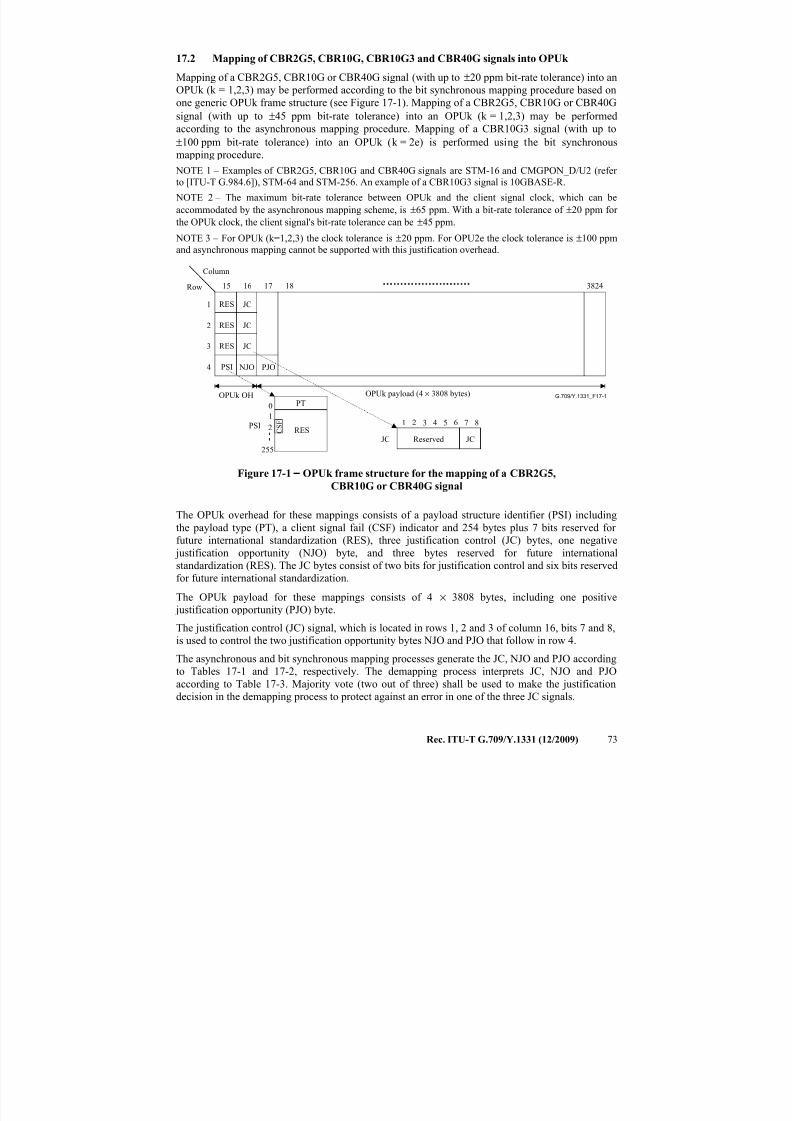
7/16/2019 G-709 ITU_T
http://slidepdf.com/reader/full/g-709-itut 81/218
Rec. ITU-T G.709/Y.1331 (12/2009) 73
17.2 Mapping of CBR2G5, CBR10G, CBR10G3 and CBR40G signals into OPUk
Mapping of a CBR2G5, CBR10G or CBR40G signal (with up to ±20 ppm bit-rate tolerance) into an
OPUk (k = 1,2,3) may be performed according to the bit synchronous mapping procedure based on
one generic OPUk frame structure (see Figure 17-1). Mapping of a CBR2G5, CBR10G or CBR40G
signal (with up to ±45 ppm bit-rate tolerance) into an OPUk (k = 1,2,3) may be performed
according to the asynchronous mapping procedure. Mapping of a CBR10G3 signal (with up to
±100 ppm bit-rate tolerance) into an OPUk (k = 2e) is performed using the bit synchronous
mapping procedure.
NOTE 1 – Examples of CBR2G5, CBR10G and CBR40G signals are STM-16 and CMGPON_D/U2 (refer
to [ITU-T G.984.6]), STM-64 and STM-256. An example of a CBR10G3 signal is 10GBASE-R.
NOTE 2 – The maximum bit-rate tolerance between OPUk and the client signal clock, which can be
accommodated by the asynchronous mapping scheme, is ±65 ppm. With a bit-rate tolerance of ±20 ppm for
the OPUk clock, the client signal's bit-rate tolerance can be ±45 ppm.
NOTE 3 – For OPUk (k=1,2,3) the clock tolerance is ±20 ppm. For OPU2e the clock tolerance is ±100 ppm
and asynchronous mapping cannot be supported with this justification overhead.
G.709/Y.1331_F17-1
Row
Column
OPUk payload (4 × 3808 bytes)
Reserved
RES
RES
RES
PSI
1
2
3
4
3824
JC
JC
JC
NJO PJO
JC
1 6 7 82 543
JCRES
255
01
PT
PSI
16 17 1815
OPUk OH
C S F
2
Figure 17-1 − OPUk frame structure for the mapping of a CBR2G5,
CBR10G or CBR40G signal
The OPUk overhead for these mappings consists of a payload structure identifier (PSI) including
the payload type (PT), a client signal fail (CSF) indicator and 254 bytes plus 7 bits reserved for
future international standardization (RES), three justification control (JC) bytes, one negative justification opportunity (NJO) byte, and three bytes reserved for future international
standardization (RES). The JC bytes consist of two bits for justification control and six bits reserved
for future international standardization.
The OPUk payload for these mappings consists of 4 × 3808 bytes, including one positive
justification opportunity (PJO) byte.
The justification control (JC) signal, which is located in rows 1, 2 and 3 of column 16, bits 7 and 8,
is used to control the two justification opportunity bytes NJO and PJO that follow in row 4.
The asynchronous and bit synchronous mapping processes generate the JC, NJO and PJO according
to Tables 17-1 and 17-2, respectively. The demapping process interprets JC, NJO and PJO
according to Table 17-3. Majority vote (two out of three) shall be used to make the justificationdecision in the demapping process to protect against an error in one of the three JC signals.
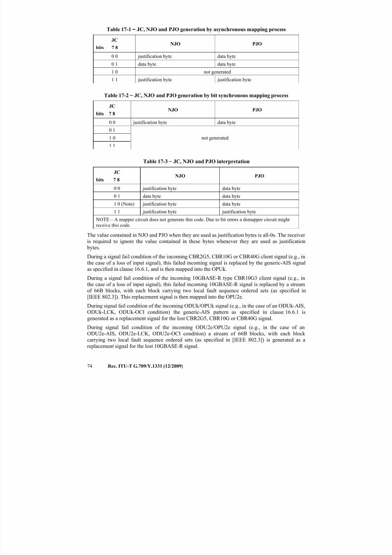
7/16/2019 G-709 ITU_T
http://slidepdf.com/reader/full/g-709-itut 82/218
74 Rec. ITU-T G.709/Y.1331 (12/2009)
Table 17-1 − JC, NJO and PJO generation by asynchronous mapping process
JC
bits 7 8NJO PJO
0 0 justification byte data byte
0 1 data byte data byte
1 0 not generated
1 1 justification byte justification byte
Table 17-2 − JC, NJO and PJO generation by bit synchronous mapping process
JC
bits 7 8NJO PJO
0 0 justification byte data byte
0 1
not generated1 0
1 1
Table 17-3 − JC, NJO and PJO interpretation
JC
bits 7 8NJO PJO
0 0 justification byte data byte
0 1 data byte data byte
1 0 (Note) justification byte data byte
1 1 justification byte justification byte
NOTE – A mapper circuit does not generate this code. Due to bit errors a demapper circuit might
receive this code.
The value contained in NJO and PJO when they are used as justification bytes is all-0s. The receiver
is required to ignore the value contained in these bytes whenever they are used as justification
bytes.
During a signal fail condition of the incoming CBR2G5, CBR10G or CBR40G client signal (e.g., in
the case of a loss of input signal), this failed incoming signal is replaced by the generic-AIS signal
as specified in clause 16.6.1, and is then mapped into the OPUk.
During a signal fail condition of the incoming 10GBASE-R type CBR10G3 client signal (e.g., in
the case of a loss of input signal), this failed incoming 10GBASE-R signal is replaced by a stream
of 66B blocks, with each block carrying two local fault sequence ordered sets (as specified in
[IEEE 802.3]). This replacement signal is then mapped into the OPU2e.
During signal fail condition of the incoming ODUk/OPUk signal (e.g., in the case of an ODUk-AIS,
ODUk-LCK, ODUk-OCI condition) the generic-AIS pattern as specified in clause 16.6.1 is
generated as a replacement signal for the lost CBR2G5, CBR10G or CBR40G signal.
During signal fail condition of the incoming ODU2e/OPU2e signal (e.g., in the case of an
ODU2e-AIS, ODU2e-LCK, ODU2e-OCI condition) a stream of 66B blocks, with each block
carrying two local fault sequence ordered sets (as specified in [IEEE 802.3]) is generated as a
replacement signal for the lost 10GBASE-R signal.
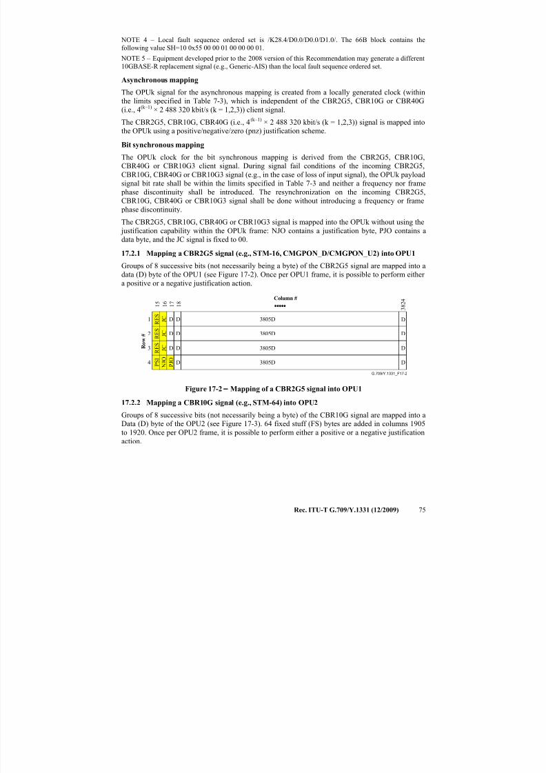
7/16/2019 G-709 ITU_T
http://slidepdf.com/reader/full/g-709-itut 83/218
Rec. ITU-T G.709/Y.1331 (12/2009) 75
NOTE 4 – Local fault sequence ordered set is /K28.4/D0.0/D0.0/D1.0/. The 66B block contains the
following value SH=10 0x55 00 00 01 00 00 00 01.
NOTE 5 – Equipment developed prior to the 2008 version of this Recommendation may generate a different
10GBASE-R replacement signal (e.g., Generic-AIS) than the local fault sequence ordered set.
Asynchronous mapping
The OPUk signal for the asynchronous mapping is created from a locally generated clock (withinthe limits specified in Table 7-3), which is independent of the CBR2G5, CBR10G or CBR40G
(i.e., 4(k–1) × 2 488 320 kbit/s (k = 1,2,3)) client signal.
The CBR2G5, CBR10G, CBR40G (i.e., 4(k–1) × 2 488 320 kbit/s (k = 1,2,3)) signal is mapped into
the OPUk using a positive/negative/zero (pnz) justification scheme.
Bit synchronous mapping
The OPUk clock for the bit synchronous mapping is derived from the CBR2G5, CBR10G,
CBR40G or CBR10G3 client signal. During signal fail conditions of the incoming CBR2G5,
CBR10G, CBR40G or CBR10G3 signal (e.g., in the case of loss of input signal), the OPUk payload
signal bit rate shall be within the limits specified in Table 7-3 and neither a frequency nor frame
phase discontinuity shall be introduced. The resynchronization on the incoming CBR2G5,
CBR10G, CBR40G or CBR10G3 signal shall be done without introducing a frequency or frame
phase discontinuity.
The CBR2G5, CBR10G, CBR40G or CBR10G3 signal is mapped into the OPUk without using the
justification capability within the OPUk frame: NJO contains a justification byte, PJO contains a
data byte, and the JC signal is fixed to 00.
17.2.1 Mapping a CBR2G5 signal (e.g., STM-16, CMGPON_D/CMGPON_U2) into OPU1
Groups of 8 successive bits (not necessarily being a byte) of the CBR2G5 signal are mapped into a
data (D) byte of the OPU1 (see Figure 17-2). Once per OPU1 frame, it is possible to perform either
a positive or a negative justification action.
G.709/Y.1331_F17-2
1 7 1 8
3 8 2 4
1
2
3
4 P J O
N J O
J C
D D D3805D
D D D3805D
D D D3805D
D D3805D
J C
J C
P S I
R E S
R E S
R E S
1 5 1 6
R o w
#
Column #
Figure 17-2 − Mapping of a CBR2G5 signal into OPU1
17.2.2 Mapping a CBR10G signal (e.g., STM-64) into OPU2
Groups of 8 successive bits (not necessarily being a byte) of the CBR10G signal are mapped into a
Data (D) byte of the OPU2 (see Figure 17-3). 64 fixed stuff (FS) bytes are added in columns 1905
to 1920. Once per OPU2 frame, it is possible to perform either a positive or a negative justification
action.
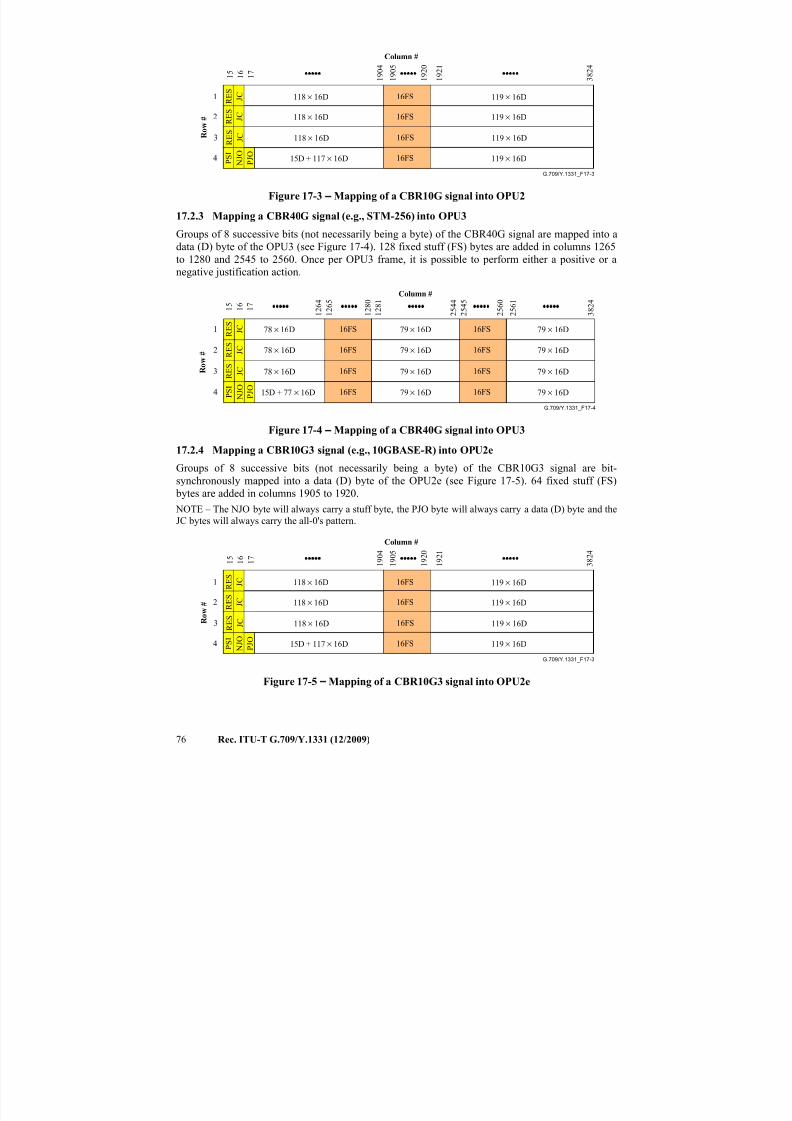
7/16/2019 G-709 ITU_T
http://slidepdf.com/reader/full/g-709-itut 84/218
76 Rec. ITU-T G.709/Y.1331 (12/2009)
G.709/Y.1331_F17-3
1 7
P J O
3 8 2 4
1 9 0 5
1 9 0 4
1 9 2 0
1 9 2 1
118 × 16D 119 × 16D
119 × 16D
119 × 16D
119 × 16D
1
2
3
4 N J O
J C
J C
J C
P S I
R E S
R E S
R E S
1 5 1 6
118 × 16D
118 × 16D
15D + 117 × 16D
16FS
16FS
16FS
16FS
R
o w
#
Column #
Figure 17-3 − Mapping of a CBR10G signal into OPU2
17.2.3 Mapping a CBR40G signal (e.g., STM-256) into OPU3
Groups of 8 successive bits (not necessarily being a byte) of the CBR40G signal are mapped into a
data (D) byte of the OPU3 (see Figure 17-4). 128 fixed stuff (FS) bytes are added in columns 1265
to 1280 and 2545 to 2560. Once per OPU3 frame, it is possible to perform either a positive or a
negative justification action.
G.709/Y.1331_F17-4
1 7
P J O
3 8 2 4
1 2 6 4
1 2 6 5
1 2 8 0
1 2 8 1
2 5 4 4
2 5 6 1
2 5 4 5
2 5 6 0
78 × 16D 79 × 16D1
2
3
4 N J O
J C
J C
J C
P S I
R E S
R E S
R E S
1 5 1 6
78 × 16D
78 × 16D
15D + 77 × 16D
16FS
16FS
16FS
16FS
79 × 16D
79 × 16D
79 × 16D
79 × 16D16FS
16FS
16FS
16FS
79 × 16D
79 × 16D
79 × 16D
R o w
#
Column #
Figure 17-4 − Mapping of a CBR40G signal into OPU3
17.2.4 Mapping a CBR10G3 signal (e.g., 10GBASE-R) into OPU2e
Groups of 8 successive bits (not necessarily being a byte) of the CBR10G3 signal are bit-
synchronously mapped into a data (D) byte of the OPU2e (see Figure 17-5). 64 fixed stuff (FS)
bytes are added in columns 1905 to 1920.
NOTE – The NJO byte will always carry a stuff byte, the PJO byte will always carry a data (D) byte and the
JC bytes will always carry the all-0's pattern.
G.709/Y.1331_F17-3
1 7
P J O
3 8 2 4
1 9 0 5
1 9 0 4
1 9 2 0
1 9 2 1
118 × 16D 119 × 16D
119 × 16D
119 × 16D
119 × 16D
1
2
3
4 N J O
J C
J C
J C
P S I
R E S
R E S
R E S
1 5 1 6
118 × 16D
118 × 16D
15D + 117 × 16D
16FS
16FS
16FS
16FS
R o w
#
Column #
Figure 17-5 − Mapping of a CBR10G3 signal into OPU2e
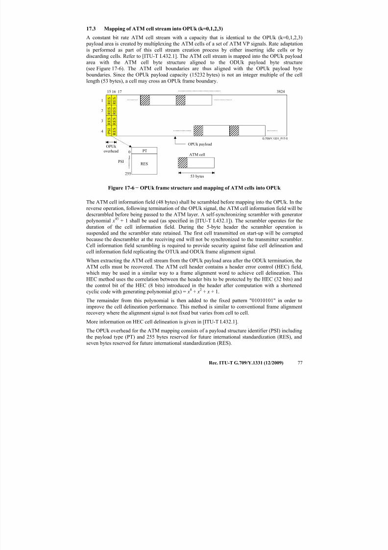
7/16/2019 G-709 ITU_T
http://slidepdf.com/reader/full/g-709-itut 85/218
Rec. ITU-T G.709/Y.1331 (12/2009) 77
17.3 Mapping of ATM cell stream into OPUk (k=0,1,2,3)
A constant bit rate ATM cell stream with a capacity that is identical to the OPUk (k=0,1,2,3)
payload area is created by multiplexing the ATM cells of a set of ATM VP signals. Rate adaptation
is performed as part of this cell stream creation process by either inserting idle cells or by
discarding cells. Refer to [ITU-T I.432.1]. The ATM cell stream is mapped into the OPUk payload
area with the ATM cell byte structure aligned to the ODUk payload byte structure
(see Figure 17-6). The ATM cell boundaries are thus aligned with the OPUk payload byte boundaries. Since the OPUk payload capacity (15232 bytes) is not an integer multiple of the cell
length (53 bytes), a cell may cross an OPUk frame boundary.
G.709/Y.1331_F17-5
OPUk payload
ATM cell
OPUk
overhead
53 bytes
17 3824
1
2
3
4 R
E S
R E S
R E S
R E S
P
S I
R E S
R E S
R E S
15 16
RES
255
0
1
PT
PSI
Figure 17-6 − OPUk frame structure and mapping of ATM cells into OPUk
The ATM cell information field (48 bytes) shall be scrambled before mapping into the OPUk. In thereverse operation, following termination of the OPUk signal, the ATM cell information field will be
descrambled before being passed to the ATM layer. A self-synchronizing scrambler with generator
polynomial x43 + 1 shall be used (as specified in [ITU-T I.432.1]). The scrambler operates for the
duration of the cell information field. During the 5-byte header the scrambler operation is
suspended and the scrambler state retained. The first cell transmitted on start-up will be corrupted
because the descrambler at the receiving end will not be synchronized to the transmitter scrambler.
Cell information field scrambling is required to provide security against false cell delineation and
cell information field replicating the OTUk and ODUk frame alignment signal.
When extracting the ATM cell stream from the OPUk payload area after the ODUk termination, the
ATM cells must be recovered. The ATM cell header contains a header error control (HEC) field,which may be used in a similar way to a frame alignment word to achieve cell delineation. This
HEC method uses the correlation between the header bits to be protected by the HEC (32 bits) and
the control bit of the HEC (8 bits) introduced in the header after computation with a shortened
cyclic code with generating polynomial g(x) = x8 + x2 + x + 1.
The remainder from this polynomial is then added to the fixed pattern "01010101" in order to
improve the cell delineation performance. This method is similar to conventional frame alignment
recovery where the alignment signal is not fixed but varies from cell to cell.
More information on HEC cell delineation is given in [ITU-T I.432.1].
The OPUk overhead for the ATM mapping consists of a payload structure identifier (PSI) including
the payload type (PT) and 255 bytes reserved for future international standardization (RES), and
seven bytes reserved for future international standardization (RES).
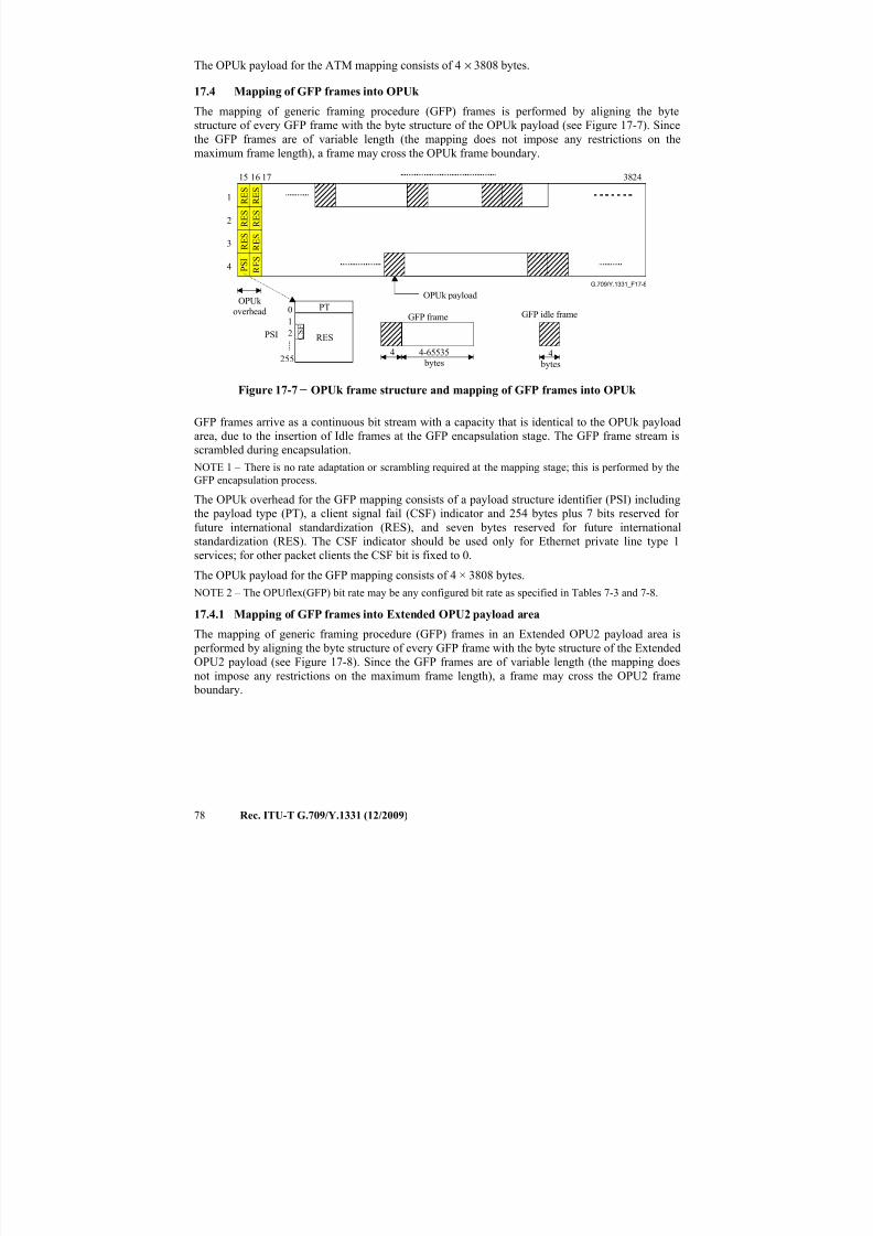
7/16/2019 G-709 ITU_T
http://slidepdf.com/reader/full/g-709-itut 86/218
78 Rec. ITU-T G.709/Y.1331 (12/2009)
The OPUk payload for the ATM mapping consists of 4 × 3808 bytes.
17.4 Mapping of GFP frames into OPUk
The mapping of generic framing procedure (GFP) frames is performed by aligning the byte
structure of every GFP frame with the byte structure of the OPUk payload (see Figure 17-7). Since
the GFP frames are of variable length (the mapping does not impose any restrictions on the
maximum frame length), a frame may cross the OPUk frame boundary.
G.709/Y.1331_F17-6
OPUk payload
GFP frame GFP idle frame
OPUk overhead
4
bytes
4-65535 bytes
17 3824
1
2
3
4 R E S
R E S
R E S
R E S
P S I
R E S
R E S
R E S
15 16
RES
255
0
1
PT
PSI
4
C S F
2
Figure 17-7 − OPUk frame structure and mapping of GFP frames into OPUk
GFP frames arrive as a continuous bit stream with a capacity that is identical to the OPUk payload
area, due to the insertion of Idle frames at the GFP encapsulation stage. The GFP frame stream is
scrambled during encapsulation. NOTE 1 – There is no rate adaptation or scrambling required at the mapping stage; this is performed by the
GFP encapsulation process.
The OPUk overhead for the GFP mapping consists of a payload structure identifier (PSI) including
the payload type (PT), a client signal fail (CSF) indicator and 254 bytes plus 7 bits reserved for
future international standardization (RES), and seven bytes reserved for future international
standardization (RES). The CSF indicator should be used only for Ethernet private line type 1
services; for other packet clients the CSF bit is fixed to 0.
The OPUk payload for the GFP mapping consists of 4 × 3808 bytes.
NOTE 2 – The OPUflex(GFP) bit rate may be any configured bit rate as specified in Tables 7-3 and 7-8.
17.4.1 Mapping of GFP frames into Extended OPU2 payload area
The mapping of generic framing procedure (GFP) frames in an Extended OPU2 payload area is
performed by aligning the byte structure of every GFP frame with the byte structure of the Extended
OPU2 payload (see Figure 17-8). Since the GFP frames are of variable length (the mapping does
not impose any restrictions on the maximum frame length), a frame may cross the OPU2 frame
boundary.
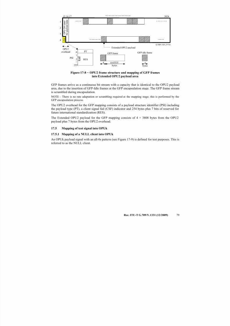
7/16/2019 G-709 ITU_T
http://slidepdf.com/reader/full/g-709-itut 87/218
Rec. ITU-T G.709/Y.1331 (12/2009) 79
G.709/Y.1331_F17-6
Extended OPU2 payload
GFP frame GFP idle frame
OPU2overhead
4
bytes
4-65535 bytes
17 3824
1
2
3
4 P S
I
15 16
RES
255
0
1
PT
PSI
4
O P U O H u s e
d
f o r p a y
l o a
d d a
t a
C S F
2
Figure 17-8 − OPU2 frame structure and mapping of GFP frames
into Extended OPU2 payload area
GFP frames arrive as a continuous bit stream with a capacity that is identical to the OPU2 payload
area, due to the insertion of GFP-Idle frames at the GFP encapsulation stage. The GFP frame stream
is scrambled during encapsulation.
NOTE – There is no rate adaptation or scrambling required at the mapping stage; this is performed by the
GFP encapsulation process.
The OPU2 overhead for the GFP mapping consists of a payload structure identifier (PSI) including
the payload type (PT), a client signal fail (CSF) indicator and 254 bytes plus 7 bits of reserved for
future international standardization (RES).
The Extended OPU2 payload for the GFP mapping consists of 4 × 3808 bytes from the OPU2 payload plus 7 bytes from the OPU2 overhead.
17.5 Mapping of test signal into OPUk
17.5.1 Mapping of a NULL client into OPUk
An OPUk payload signal with an all-0s pattern (see Figure 17-9) is defined for test purposes. This is
referred to as the NULL client.
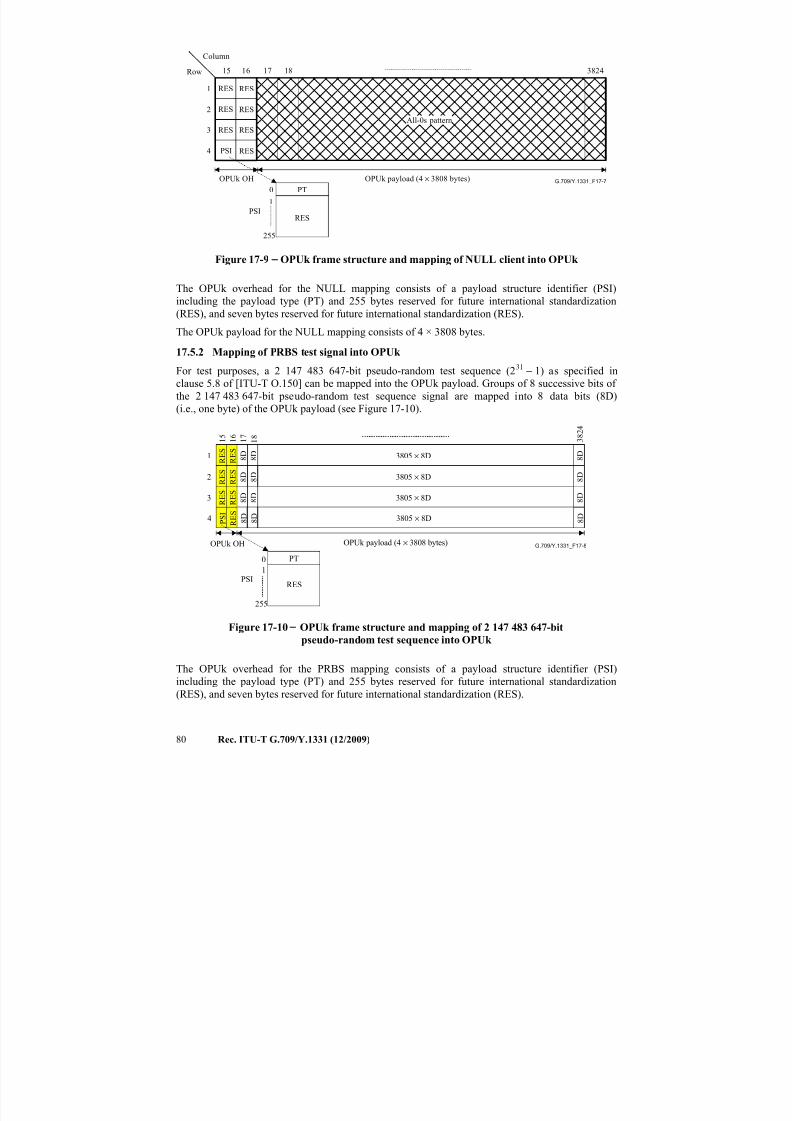
7/16/2019 G-709 ITU_T
http://slidepdf.com/reader/full/g-709-itut 88/218
80 Rec. ITU-T G.709/Y.1331 (12/2009)
G.709/Y.1331_F17-7
Row
Column
OPUk payload (4 × 3808 bytes)
All-0s pattern
RES
255
0
1
PT
PSI
1
2
3
4
16 17 38241815
RES
RES
RES
RES
RES
RES
RES
PSI
OPUk OH
Figure 17-9 − OPUk frame structure and mapping of NULL client into OPUk
The OPUk overhead for the NULL mapping consists of a payload structure identifier (PSI)
including the payload type (PT) and 255 bytes reserved for future international standardization
(RES), and seven bytes reserved for future international standardization (RES).
The OPUk payload for the NULL mapping consists of 4 × 3808 bytes.
17.5.2 Mapping of PRBS test signal into OPUk
For test purposes, a 2 147 483 647-bit pseudo-random test sequence (231 − 1) as specified in
clause 5.8 of [ITU-T O.150] can be mapped into the OPUk payload. Groups of 8 successive bits of
the 2 147 483 647-bit pseudo-random test sequence signal are mapped into 8 data bits (8D)
(i.e., one byte) of the OPUk payload (see Figure 17-10).
G.709/Y.1331_F17-8OPUk payload (4 × 3808 bytes)
1 7
3 8 2 4
1 8
8 D 8 D
8 D3805 × 8D
8 D 8 D
8 D3805 × 8D
8 D 8 D
8 D3805 × 8D
8 D 8 D
8 D3805 × 8D
1
2
3
4 R E S
R E S
R E S
R E S
P S I
R E S
R E S
R E S
1 5 1 6
OPUk OH
RES
255
0
1
PT
PSI
Figure 17-10 − OPUk frame structure and mapping of 2 147 483 647-bit
pseudo-random test sequence into OPUk
The OPUk overhead for the PRBS mapping consists of a payload structure identifier (PSI)
including the payload type (PT) and 255 bytes reserved for future international standardization(RES), and seven bytes reserved for future international standardization (RES).
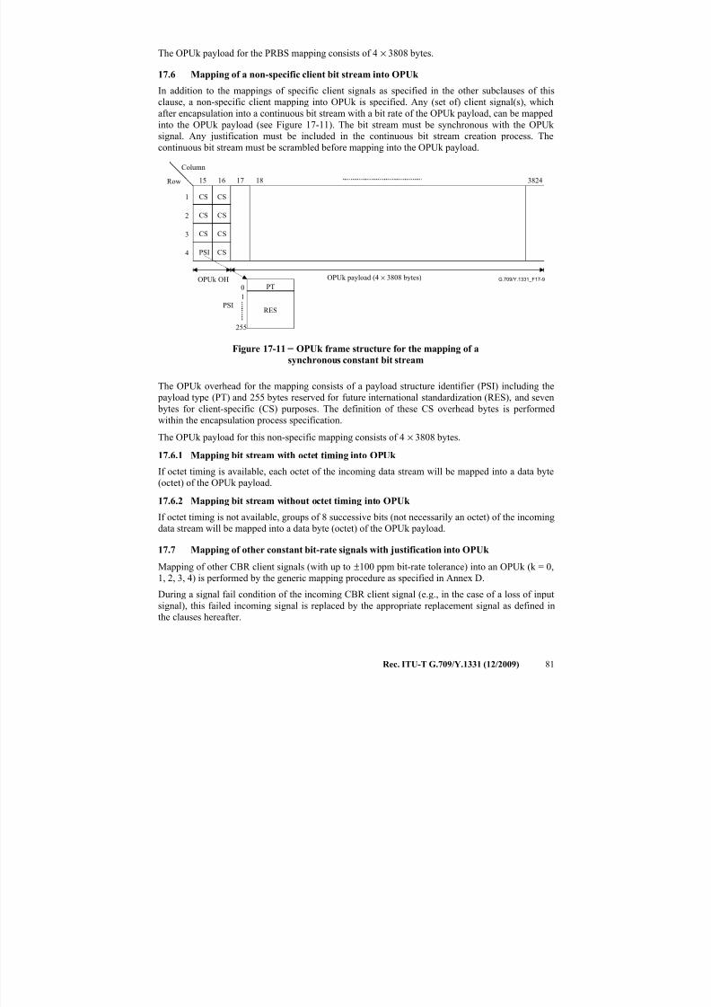
7/16/2019 G-709 ITU_T
http://slidepdf.com/reader/full/g-709-itut 89/218
Rec. ITU-T G.709/Y.1331 (12/2009) 81
The OPUk payload for the PRBS mapping consists of 4 × 3808 bytes.
17.6 Mapping of a non-specific client bit stream into OPUk
In addition to the mappings of specific client signals as specified in the other subclauses of this
clause, a non-specific client mapping into OPUk is specified. Any (set of) client signal(s), which
after encapsulation into a continuous bit stream with a bit rate of the OPUk payload, can be mapped
into the OPUk payload (see Figure 17-11). The bit stream must be synchronous with the OPUk signal. Any justification must be included in the continuous bit stream creation process. The
continuous bit stream must be scrambled before mapping into the OPUk payload.
G.709/Y.1331_F17-9
Row
Column
OPUk payload (4 × 3808 bytes)
CS1
2
3
4
3824
RES
255
0
1
PT
PSI
16 17 1815
OPUk OH
CS
CS CS
CS CS
PSI CS
Figure 17-11 − OPUk frame structure for the mapping of a
synchronous constant bit stream
The OPUk overhead for the mapping consists of a payload structure identifier (PSI) including the
payload type (PT) and 255 bytes reserved for future international standardization (RES), and seven
bytes for client-specific (CS) purposes. The definition of these CS overhead bytes is performed
within the encapsulation process specification.
The OPUk payload for this non-specific mapping consists of 4 × 3808 bytes.
17.6.1 Mapping bit stream with octet timing into OPUk
If octet timing is available, each octet of the incoming data stream will be mapped into a data byte
(octet) of the OPUk payload.
17.6.2 Mapping bit stream without octet timing into OPUk
If octet timing is not available, groups of 8 successive bits (not necessarily an octet) of the incoming
data stream will be mapped into a data byte (octet) of the OPUk payload.
17.7 Mapping of other constant bit-rate signals with justification into OPUk
Mapping of other CBR client signals (with up to ±100 ppm bit-rate tolerance) into an OPUk (k = 0,
1, 2, 3, 4) is performed by the generic mapping procedure as specified in Annex D.
During a signal fail condition of the incoming CBR client signal (e.g., in the case of a loss of input
signal), this failed incoming signal is replaced by the appropriate replacement signal as defined in
the clauses hereafter.
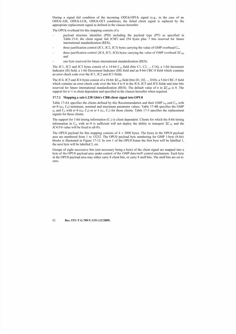
7/16/2019 G-709 ITU_T
http://slidepdf.com/reader/full/g-709-itut 90/218
82 Rec. ITU-T G.709/Y.1331 (12/2009)
During a signal fail condition of the incoming ODUk/OPUk signal (e.g., in the case of an
ODUk-AIS, ODUk-LCK, ODUk-OCI condition), the failed client signal is replaced by the
appropriate replacement signal as defined in the clauses hereafter.
The OPUk overhead for this mapping consists of a
– payload structure identifier (PSI) including the payload type (PT) as specified in
Table 15-8, the client signal fail (CSF) and 254 bytes plus 7 bits reserved for futureinternational standardization (RES),
– three justification control (JC1, JC2, JC3) bytes carrying the value of GMP overhead Cm,
– three justification control (JC4, JC5, JC6) bytes carrying the value of GMP overhead ΣCnD
and
– one byte reserved for future international standardization (RES).
The JC1, JC2 and JC3 bytes consist of a 14-bit Cm field (bits C1, C2, .., C14), a 1-bit Increment
Indicator (II) field, a 1-bit Decrement Indicator (DI) field and an 8-bit CRC-8 field which contains
an error check code over the JC1, JC2 and JC3 fields.
The JC4, JC5 and JC6 bytes consist of a 10-bit ΣCnD field (bits D1, D2, .., D10), a 5-bit CRC-5 fieldwhich contains an error check code over the bits 4 to 8 in the JC4, JC5 and JC6 fields and nine bits
reserved for future international standardization (RES). The default value of n in ΣCnD is 8. The
support for n=1 is client dependent and specified in the clauses hereafter when required.
17.7.1 Mapping a sub-1.238 Gbit/s CBR client signal into OPU0
Table 17-4A specifies the clients defined by this Recommendation and their GMP cm and Cm with
m=8 (c8, C8) minimum, nominal and maximum parameter values. Table 17-4B specifies the GMP
cn and Cn with n=8 (c8, C8) or n=1 (c1, C1) for those clients. Table 17-5 specifies the replacement
signals for those clients.
The support for 1-bit timing information (C1) is client dependent. Clients for which the 8-bit timing
information in Cm with m=8 is sufficient will not deploy the ability to transport ΣC1D and the
JC4/5/6 value will be fixed to all-0's.
The OPU0 payload for this mapping consists of 4 × 3808 bytes. The bytes in the OPU0 payload
area are numbered from 1 to 15232. The OPU0 payload byte numbering for GMP 1-byte (8-bit)
blocks is illustrated in Figure 17-12. In row 1 of the OPU0 frame the first byte will be labelled 1,
the next byte will be labelled 2, etc.
Groups of eight successive bits (not necessary being a byte) of the client signal are mapped into a
byte of the OPU0 payload area under control of the GMP data/stuff control mechanism. Each byte
in the OPU0 payload area may either carry 8 client bits, or carry 8 stuff bits. The stuff bits are set to
zero.
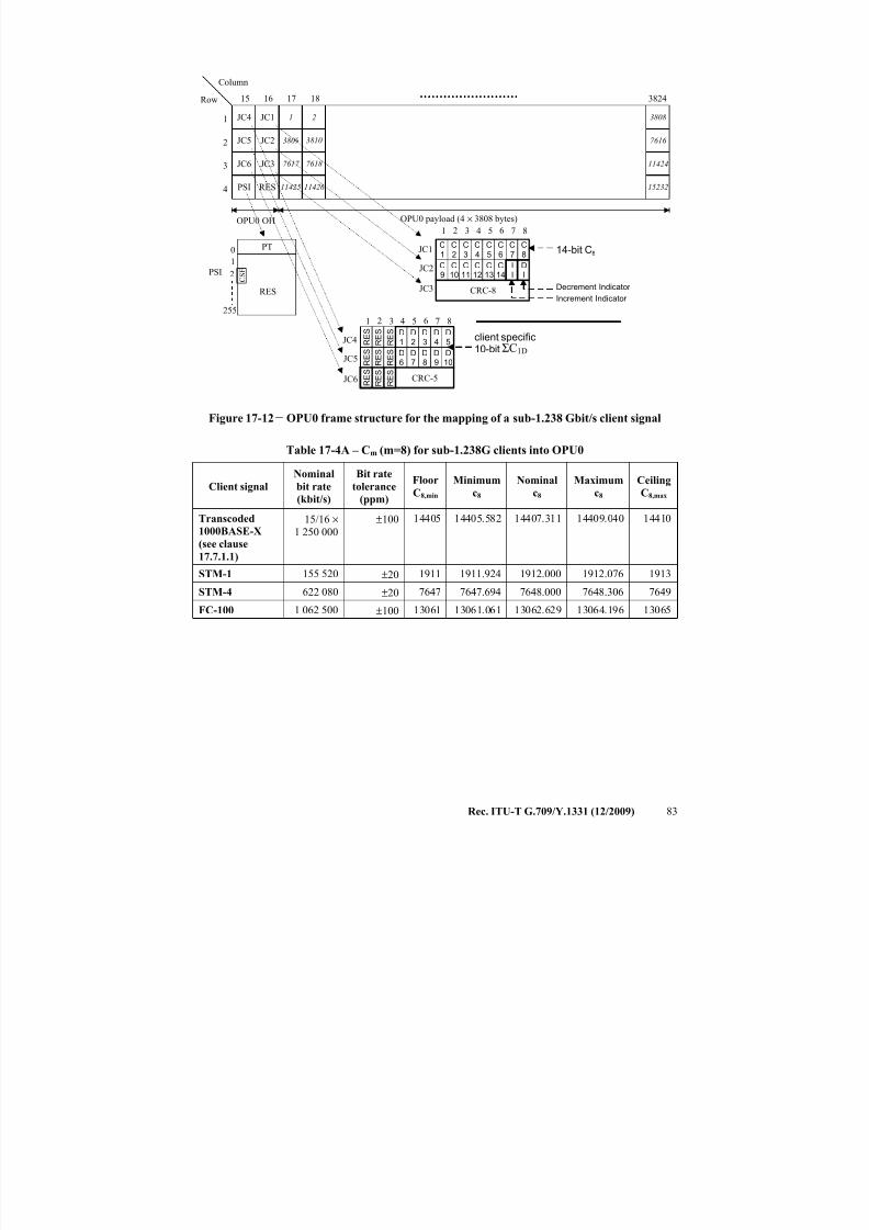
7/16/2019 G-709 ITU_T
http://slidepdf.com/reader/full/g-709-itut 91/218
Rec. ITU-T G.709/Y.1331 (12/2009) 83
Row
Column
OPU0 payload (4 × 3808 bytes)
JC4
JC5
JC6
PSI
1
2
3
4
3824
JC1
JC2
JC3
RES
1 6 7 82 543
JC1
RES
255
0
1
PT
PSI
16 17 1815
OPU0 OH
CRC-8
JC2
JC3
C9
C10
C11
C12
C13
C14
II
DI
C
1
C
2
C
3
C
4
C
5
C
6
C
7
C
8
Increment Indicator
Decrement Indicator
14-bit C8
1
3809
7617
11425
2
3810
7618
11426
3808
7616
11424
15232
C S F2
1 6 7 82 543
JC4
JC5
JC6
client specific10-bit
CRC-5
R E SD
6D7
D8
D9
D10
R E S
R E S
R E SD
1D2
D3
D4
D5
R E S
R E S ΣC1D
R E S
R E S
R E S
Figure 17-12 − OPU0 frame structure for the mapping of a sub-1.238 Gbit/s client signal
Table 17-4A – Cm (m=8) for sub-1.238G clients into OPU0
Client signal
Nominal
bit rate
(kbit/s)
Bit rate
tolerance
(ppm)
Floor
C8,min
Minimum
c8
Nominal
c8
Maximum
c8
Ceiling
C8,max
Transcoded
1000BASE-X
(see clause
17.7.1.1)
15/16 ×
1 250 000
±100 14405 14405.582 14407.311 14409.040 14410
STM-1 155 520 ±20 1911 1911.924 1912.000 1912.076 1913
STM-4 622 080 ±20 7647 7647.694 7648.000 7648.306 7649FC-100 1 062 500 ±100 13061 13061.061 13062.629 13064.196 13065
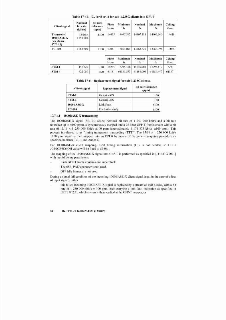
7/16/2019 G-709 ITU_T
http://slidepdf.com/reader/full/g-709-itut 92/218
84 Rec. ITU-T G.709/Y.1331 (12/2009)
Table 17-4B – Cn (n=8 or 1) for sub-1.238G clients into OPU0
Client signal
Nominal
bit rate
(kbit/s)
Bit rate
tolerance
(ppm)
Floor
C8,min
Minimum
c8
Nominal
c8
Maximum
c8
Ceiling
C8,max
Transcoded
1000BASE-X(see clause
17.7.1.1)
15/16 ×
1 250 000
±100 14405 14405.582 14407.311 14409.040 14410
FC-100 1 062 500 ±100 13061 13061.061 13062.629 13064.196 13065
Floor
C1,min
Minimum
c1
Nominal
c1
Maximum
c1
Ceiling
C1,max
STM-1 155 520 ±20 15295 15295.338 15296.000 15296.612 15297
STM-4 622 080 ±20 61181 61181.553 61184.000 61186.447 61187
Table 17-5 – Replacement signal for sub-1.238G clients
Client signal Replacement SignalBit rate tolerance
(ppm)
STM-1 Generic-AIS ±20
STM-4 Generic-AIS ±20
1000BASE-X Link Fault ±100
FC-100 For further study ±100
17.7.1.1 1000BASE-X transcodingThe 1000BASE-X signal (8B/10B coded, nominal bit rate of 1 250 000 kbit/s and a bit rate
tolerance up to ±100 ppm) is synchronously mapped into a 75-octet GFP-T frame stream with a bit
rate of 15/16 × 1 250 000 kbit/s ±100 ppm (approximately 1 171 875 kbit/s ±100 ppm). This
process is referred to as "timing transparent transcoding (TTT)". The 15/16 × 1 250 000 kbit/s
±100 ppm signal is then mapped into an OPU0 by means of the generic mapping procedure as
specified in clause 17.7.1 and Annex D.
For 1000BASE-X client mapping, 1-bit timing information (C1) is not needed, so OPU0
JC4/JC5/JC6 OH value will be fixed to all-0's.
The mapping of the 1000BASE-X signal into GFP-T is performed as specified in [ITU-T G.7041]with the following parameters:
– Each GFP-T frame contains one superblock,
– The 65B_PAD character is not used,
– GFP Idle frames are not used.
During a signal fail condition of the incoming 1000BASE-X client signal (e.g., in the case of a loss
of input signal), either
– this failed incoming 1000BASE-X signal is replaced by a stream of 10B blocks, with a bit
rate of 1 250 000 kbit/s ± 100 ppm, each carrying a link fault indication as specified in
[IEEE 802.3], which stream is then applied at the GFP-T mapper, or
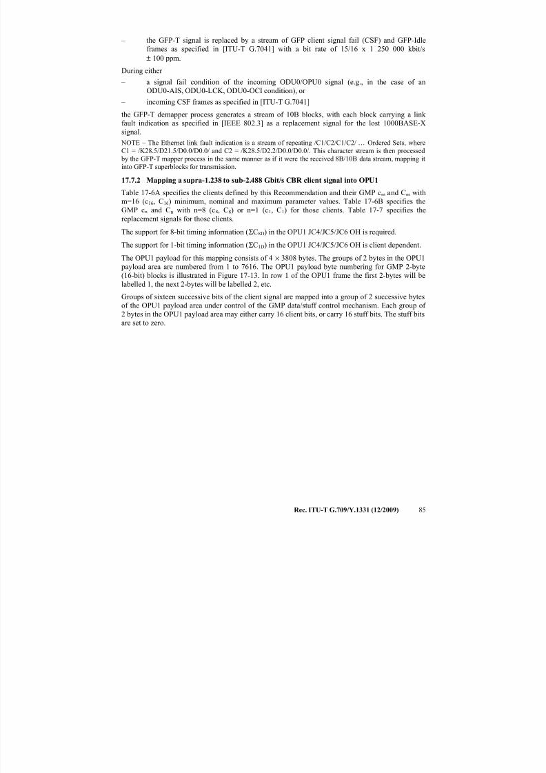
7/16/2019 G-709 ITU_T
http://slidepdf.com/reader/full/g-709-itut 93/218
Rec. ITU-T G.709/Y.1331 (12/2009) 85
– the GFP-T signal is replaced by a stream of GFP client signal fail (CSF) and GFP-Idle
frames as specified in [ITU-T G.7041] with a bit rate of 15/16 x 1 250 000 kbit/s
± 100 ppm.
During either
– a signal fail condition of the incoming ODU0/OPU0 signal (e.g., in the case of an
ODU0-AIS, ODU0-LCK, ODU0-OCI condition), or – incoming CSF frames as specified in [ITU-T G.7041]
the GFP-T demapper process generates a stream of 10B blocks, with each block carrying a link
fault indication as specified in [IEEE 802.3] as a replacement signal for the lost 1000BASE-X
signal.
NOTE – The Ethernet link fault indication is a stream of repeating /C1/C2/C1/C2/ … Ordered Sets, where
C1 = /K28.5/D21.5/D0.0/D0.0/ and C2 = /K28.5/D2.2/D0.0/D0.0/. This character stream is then processed
by the GFP-T mapper process in the same manner as if it were the received 8B/10B data stream, mapping it
into GFP-T superblocks for transmission.
17.7.2 Mapping a supra-1.238 to sub-2.488 Gbit/s CBR client signal into OPU1
Table 17-6A specifies the clients defined by this Recommendation and their GMP cm and Cm with
m=16 (c16, C16) minimum, nominal and maximum parameter values. Table 17-6B specifies the
GMP cn and Cn with n=8 (c8, C8) or n=1 (c1, C1) for those clients. Table 17-7 specifies the
replacement signals for those clients.
The support for 8-bit timing information (ΣC8D) in the OPU1 JC4/JC5/JC6 OH is required.
The support for 1-bit timing information (ΣC1D) in the OPU1 JC4/JC5/JC6 OH is client dependent.
The OPU1 payload for this mapping consists of 4 × 3808 bytes. The groups of 2 bytes in the OPU1
payload area are numbered from 1 to 7616. The OPU1 payload byte numbering for GMP 2-byte
(16-bit) blocks is illustrated in Figure 17-13. In row 1 of the OPU1 frame the first 2-bytes will be
labelled 1, the next 2-bytes will be labelled 2, etc.
Groups of sixteen successive bits of the client signal are mapped into a group of 2 successive bytes
of the OPU1 payload area under control of the GMP data/stuff control mechanism. Each group of
2 bytes in the OPU1 payload area may either carry 16 client bits, or carry 16 stuff bits. The stuff bits
are set to zero.
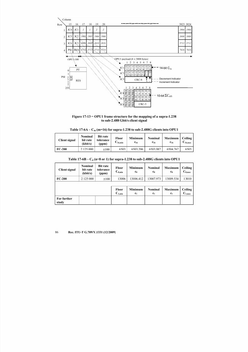
7/16/2019 G-709 ITU_T
http://slidepdf.com/reader/full/g-709-itut 94/218
86 Rec. ITU-T G.709/Y.1331 (12/2009)
Row
Column
OPU1 payload (4 × 3808 bytes)
JC4
JC5
JC6
PSI
1
2
3
4
3824
JC1
JC2
JC3
RES
1 6 7 82 543
JC1
16 17 1815
OPU1 OH
CRC-8
JC2
JC3
C9
C10
C11
C12
C13
C14
II
DI
C1
C2
C3
C4
C5
C6
C7
C8
Increment Indicator
Decrement Indicator
14-bit C16
1
1905
3809
5713
1
1905
3809
5713
1904
3808
5712
7616
1904
3808
5712
7616
382319 20
2
1906
3810
5714
2
1906
3810
5714
RES
255
0
1
PT
PSI C S F2
JC4
JC5
JC6
ΣCnD
1 6 7 82 543
10-bit
CRC-5
R E SD
6D7
D8
D9
D10
R E S
R E S
R E SD
1D2
D3
D4
D5
R E S
R E S
R E S
R E S
R E S
Figure 17-13 − OPU1 frame structure for the mapping of a supra-1.238
to sub-2.488 Gbit/s client signal
Table 17-6A – Cm (m=16) for supra-1.238 to sub-2.488G clients into OPU1
Client signal
Nominal
bit rate
(kbit/s)
Bit rate
tolerance
(ppm)
Floor
C16,min
Minimum
c16
Nominal
c16
Maximum
c16
Ceiling
C16,max
FC-200 2 125 000 ±100 6503 6503.206 6503.987 6504.767 6505
Table 17-6B – Cn (n=8 or 1) for supra-1.238 to sub-2.488G clients into OPU1
Client signal
Nominal
bit rate(kbit/s)
Bit rate
tolerance(ppm)
Floor
C8,min
Minimum
c8
Nominal
c8
Maximum
c8
Ceiling
C8,max
FC-200 2 125 000 ±100 13006 13006.412 13007.973 13009.534 13010
Floor
C1,min
Minimum
c1
Nominal
c1
Maximum
c1
Ceiling
C1,max
For further
study
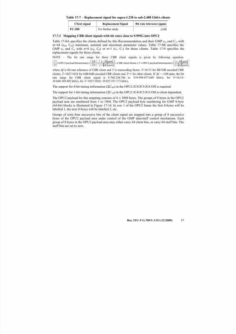
7/16/2019 G-709 ITU_T
http://slidepdf.com/reader/full/g-709-itut 95/218
Rec. ITU-T G.709/Y.1331 (12/2009) 87
Table 17-7 – Replacement signal for supra-1.238 to sub-2.488 Gbit/s clients
Client signal Replacement Signal Bit rate tolerance (ppm)
FC-200 For further study ±100
17.7.3 Mapping CBR client signals with bit rates close to 9.995G into OPU2
Table 17-8A specifies the clients defined by this Recommendation and their GMP cm and Cm withm=64 (c64, C64) minimum, nominal and maximum parameter values. Table 17-8B specifies the
GMP cn and Cn with n=8 (c8, C8) or n=1 (c1, C1) for those clients. Table 17-9 specifies the
replacement signals for those clients.
NOTE – The bit rate range for those CBR client signals is given by following equation:
[ ][ ]
[ ][ ]
Δ+
−××≤<
Δ+
−×
××
ppm f
ppmT
ppm f
ppm
1
201m) bitrate(no payloadOPU2 bitrateclientCBR
1
201
239
238m) bitrate(no payloadOPU2
8
7
where Δ f is bit-rate tolerance of CBR client and T is transcoding factor. T =16/15 for 8B/10B encoded CBR
clients, T =1027/1024 for 64B/66B encoded CBR clients and T =1 for other clients. If Δ f = ±100 ppm, the bit
rate range for CBR client signal is 8 708 228.746 to T ×9 994 077.649 kbit/s; for T =16/15:
10 660 349.492 kbit/s, for T =1027/1024: 10 023 357.173 kbit/s.
The support for 8-bit timing information (ΣC8D) in the OPU2 JC4/JC5/JC6 OH is required.
The support for 1-bit timing information (ΣC1D) in the OPU2 JC4/JC5/JC6 OH is client dependent.
The OPU2 payload for this mapping consists of 4 × 3808 bytes. The groups of 8 bytes in the OPU2
payload area are numbered from 1 to 1904. The OPU2 payload byte numbering for GMP 8-byte
(64-bit) blocks is illustrated in Figure 17-14. In row 1 of the OPU2 frame the first 8-bytes will be
labelled 1, the next 8-bytes will be labelled 2, etc.
Groups of sixty-four successive bits of the client signal are mapped into a group of 8 successive
bytes of the OPU2 payload area under control of the GMP data/stuff control mechanism. Each
group of 8 bytes in the OPU2 payload area may either carry 64 client bits, or carry 64 stuff bits. Thestuff bits are set to zero.
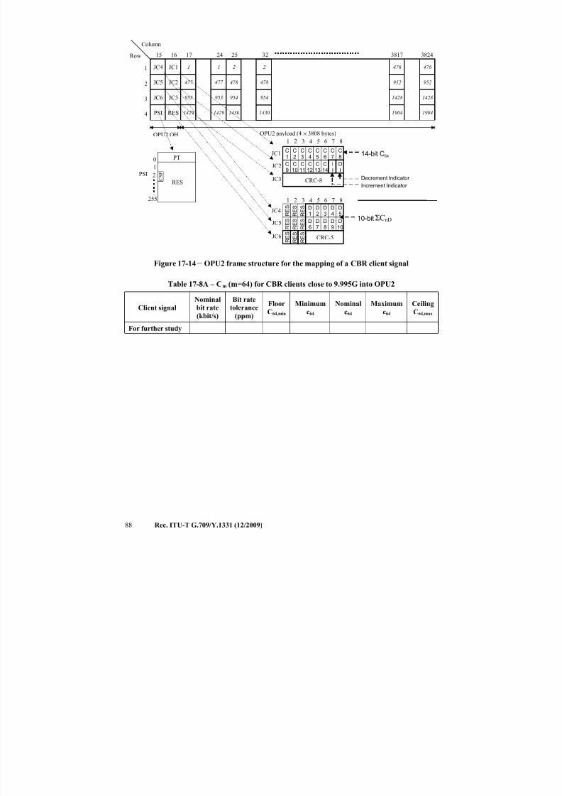
7/16/2019 G-709 ITU_T
http://slidepdf.com/reader/full/g-709-itut 96/218
88 Rec. ITU-T G.709/Y.1331 (12/2009)
Row
Column
OPU2 payload (4 × 3808 bytes)
JC4
JC5
JC6
PSI
1
2
3
4
3824
JC1
JC2
JC3
RES
1 6 7 82 543
JC1
16 17 2415
OPU2 OH
CRC-8
JC2
JC3
C9
C10
C11
C12
C13
C14
II
DI
C1
C2
C3
C4
C5
C6
C7
C8
Increment Indicator
Decrement Indicator
14-bit C64
1
477
953
1429
1
477
953
1429
476
952
1428
1904
476
952
1428
1904
381725 32
2
478
954
1430
2
478
954
1430
RES
255
0
1
PT
PSI C S F2
JC4
JC5
JC6
1 6 7 82 543
10-bit
CRC-5
R E SD
6D7
D8
D9
D10
R E S
R E S
R E SD
1D2
D3
D4
D5
R E S
R E S ΣCnD
R E S
R E S
R E S
Figure 17-14 − OPU2 frame structure for the mapping of a CBR client signal
Table 17-8A – Cm (m=64) for CBR clients close to 9.995G into OPU2
Client signal
Nominal
bit rate
(kbit/s)
Bit rate
tolerance
(ppm)
Floor
C64,min
Minimum
c64
Nominal
c64
Maximum
c64
Ceiling
C64,max
For further study
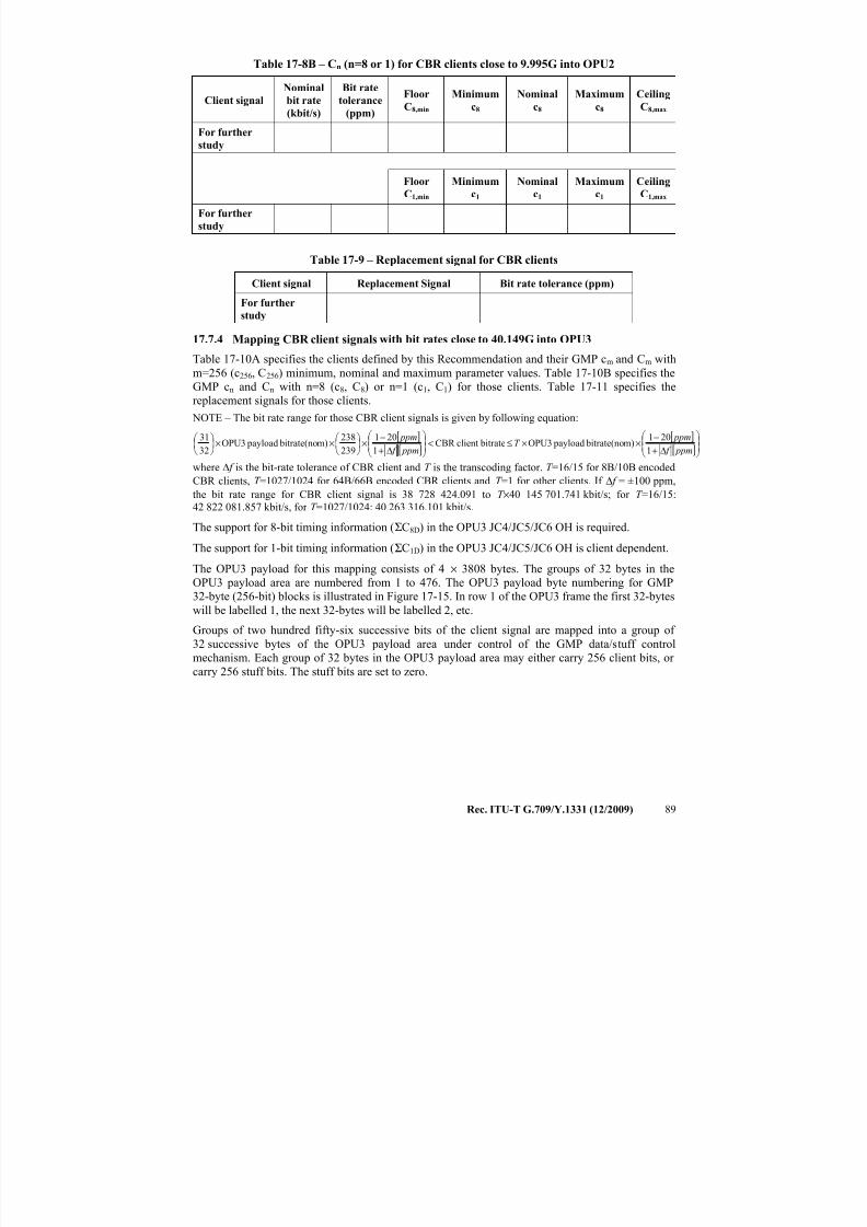
7/16/2019 G-709 ITU_T
http://slidepdf.com/reader/full/g-709-itut 97/218
Rec. ITU-T G.709/Y.1331 (12/2009) 89
Table 17-8B – Cn (n=8 or 1) for CBR clients close to 9.995G into OPU2
Client signal
Nominal
bit rate
(kbit/s)
Bit rate
tolerance
(ppm)
Floor
C8,min
Minimum
c8
Nominal
c8
Maximum
c8
Ceiling
C8,max
For further
study
Floor
C1,min
Minimum
c1
Nominal
c1
Maximum
c1
Ceiling
C1,max
For further
study
Table 17-9 – Replacement signal for CBR clients
Client signal Replacement Signal Bit rate tolerance (ppm)
For further
study
17.7.4 Mapping CBR client signals with bit rates close to 40.149G into OPU3
Table 17-10A specifies the clients defined by this Recommendation and their GMP cm and Cm with
m=256 (c256, C256) minimum, nominal and maximum parameter values. Table 17-10B specifies the
GMP cn and Cn with n=8 (c8, C8) or n=1 (c1, C1) for those clients. Table 17-11 specifies the
replacement signals for those clients.
NOTE – The bit rate range for those CBR client signals is given by following equation:
[ ]
[ ]
[ ]
[ ]
Δ+
−
××≤<
Δ+
−
×
××
ppm f
ppm
T ppm f
ppm
1
201
m) bitrate(no payloadOPU3 bitrateclientCBR 1
201
239
238
m) bitrate(no payloadOPU332
31
where Δ f is the bit-rate tolerance of CBR client and T is the transcoding factor. T =16/15 for 8B/10B encoded
CBR clients, T =1027/1024 for 64B/66B encoded CBR clients and T =1 for other clients. If Δ f = ±100 ppm,
the bit rate range for CBR client signal is 38 728 424.091 to T ×40 145 701.741 kbit/s; for T =16/15:
42 822 081.857 kbit/s, for T =1027/1024: 40 263 316.101 kbit/s.
The support for 8-bit timing information (ΣC8D) in the OPU3 JC4/JC5/JC6 OH is required.
The support for 1-bit timing information (ΣC1D) in the OPU3 JC4/JC5/JC6 OH is client dependent.
The OPU3 payload for this mapping consists of 4 × 3808 bytes. The groups of 32 bytes in the
OPU3 payload area are numbered from 1 to 476. The OPU3 payload byte numbering for GMP
32-byte (256-bit) blocks is illustrated in Figure 17-15. In row 1 of the OPU3 frame the first 32-byteswill be labelled 1, the next 32-bytes will be labelled 2, etc.
Groups of two hundred fifty-six successive bits of the client signal are mapped into a group of
32 successive bytes of the OPU3 payload area under control of the GMP data/stuff control
mechanism. Each group of 32 bytes in the OPU3 payload area may either carry 256 client bits, or
carry 256 stuff bits. The stuff bits are set to zero.
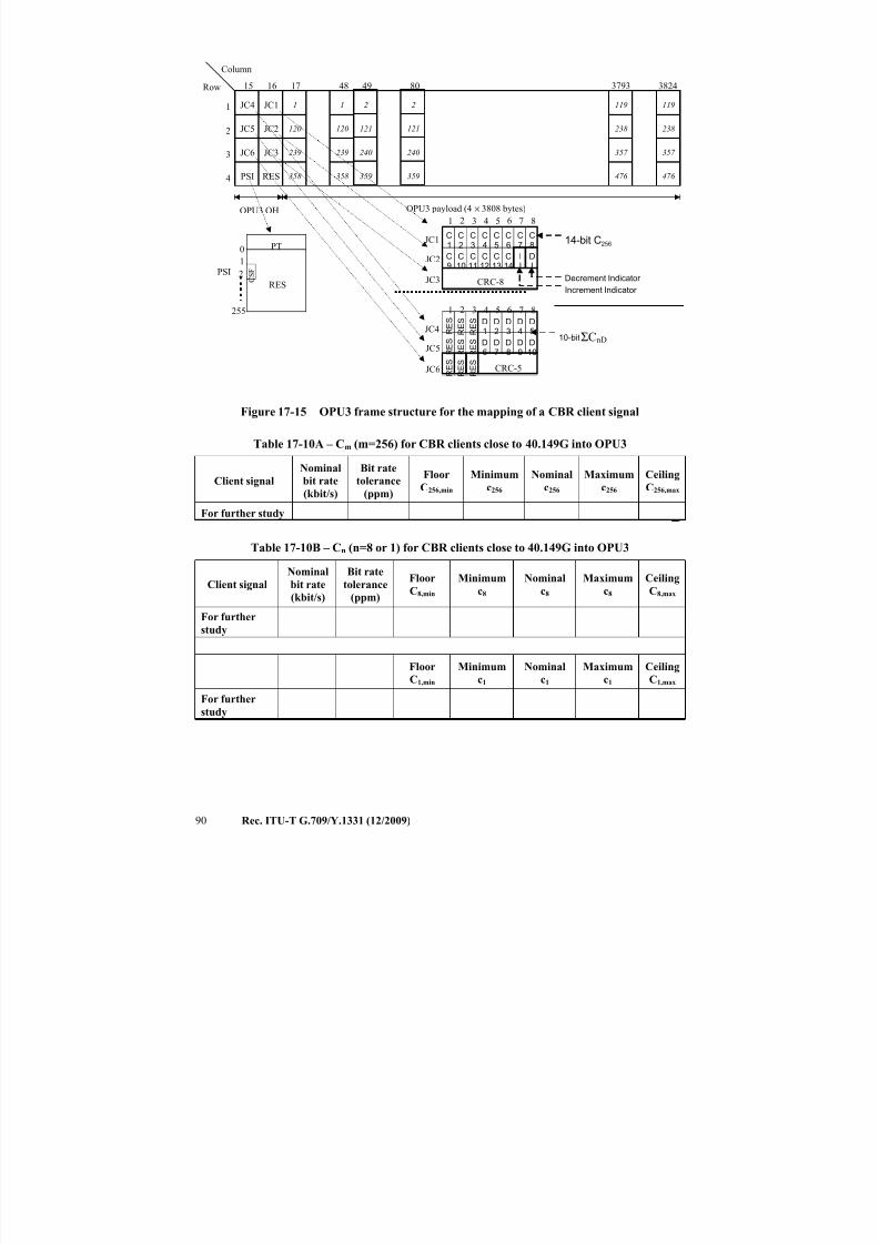
7/16/2019 G-709 ITU_T
http://slidepdf.com/reader/full/g-709-itut 98/218
90 Rec. ITU-T G.709/Y.1331 (12/2009)
Row
Column
OPU3 payload (4 × 3808 bytes)
JC4
JC5
JC6
PSI
1
2
3
4
3824
JC1
JC2
JC3
RES
1 6 7 82 543
JC1
16 17 4815
OPU3 OH
CRC-8
JC2
JC3
C9
C10
C11
C12
C13
C14
II
DI
C1
C2
C3
C4
C5
C6
C7
C8
Increment Indicator
Decrement Indicator
14-bit C256
1
120
239
358
1
120
239
358
119
238
357
476
119
238
357
476
379349 80
2
121
240
359
2
121
240
359
RES
255
0
1
PT
PSI C S F2
JC4
JC5
JC6
1 6 7 82 543
10-bit
CRC-5
R E SD
6D7
D8
D9
D10
R E S
R E S
R E SD
1D2
D3
D4
D5
R E S
R E S ΣCnD
R E S
R E S
R E S
Figure 17-15 − OPU3 frame structure for the mapping of a CBR client signal
Table 17-10A – Cm (m=256) for CBR clients close to 40.149G into OPU3
Client signal
Nominal
bit rate
(kbit/s)
Bit rate
tolerance
(ppm)
Floor
C256,min
Minimum
c256
Nominal
c256
Maximum
c256
Ceiling
C256,max
For further study
Table 17-10B – Cn (n=8 or 1) for CBR clients close to 40.149G into OPU3
Client signal
Nominal
bit rate
(kbit/s)
Bit rate
tolerance
(ppm)
Floor
C8,min
Minimum
c8
Nominal
c8
Maximum
c8
Ceiling
C8,max
For further
study
Floor
C1,min
Minimum
c1
Nominal
c1
Maximum
c1
Ceiling
C1,max
For further
study
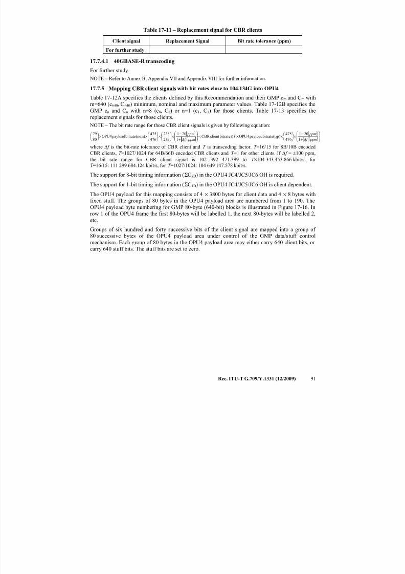
7/16/2019 G-709 ITU_T
http://slidepdf.com/reader/full/g-709-itut 99/218
Rec. ITU-T G.709/Y.1331 (12/2009) 91
Table 17-11 – Replacement signal for CBR clients
Client signal Replacement Signal Bit rate tolerance (ppm)
For further study
17.7.4.1 40GBASE-R transcoding
For further study.
NOTE – Refer to Annex B, Appendix VII and Appendix VIII for further information.
17.7.5 Mapping CBR client signals with bit rates close to 104.134G into OPU4
Table 17-12A specifies the clients defined by this Recommendation and their GMP cm and Cm with
m=640 (c640, C640) minimum, nominal and maximum parameter values. Table 17-12B specifies the
GMP cn and Cn with n=8 (c8, C8) or n=1 (c1, C1) for those clients. Table 17-13 specifies the
replacement signals for those clients.
NOTE – The bit rate range for those CBR client signals is given by following equation:
[ ]
[ ]
[ ]
[ ]
Δ+
−×
××≤<
Δ+
−×
×
××
ppm f
ppmT
ppm f
ppm
1
201
476
475 p) bitrate(ty payloadOPU4 bitrateclientCBR
1
201
239
238
476
475m) bitrate(no payloadOPU4
80
79
where Δ f is the bit-rate tolerance of CBR client and T is transcoding factor. T =16/15 for 8B/10B encoded
CBR clients, T =1027/1024 for 64B/66B encoded CBR clients and T =1 for other clients. If Δ f = ±100 ppm,
the bit rate range for CBR client signal is 102 392 471.399 to T ×104 343 453.866 kbit/s; for
T =16/15: 111 299 684.124 kbit/s, for T =1027/1024: 104 649 147.578 kbit/s.
The support for 8-bit timing information (ΣC8D) in the OPU4 JC4/JC5/JC6 OH is required.
The support for 1-bit timing information (ΣC1D) in the OPU4 JC4/JC5/JC6 OH is client dependent.
The OPU4 payload for this mapping consists of 4 × 3800 bytes for client data and 4 × 8 bytes with
fixed stuff. The groups of 80 bytes in the OPU4 payload area are numbered from 1 to 190. The
OPU4 payload byte numbering for GMP 80-byte (640-bit) blocks is illustrated in Figure 17-16. Inrow 1 of the OPU4 frame the first 80-bytes will be labelled 1, the next 80-bytes will be labelled 2,
etc.
Groups of six hundred and forty successive bits of the client signal are mapped into a group of
80 successive bytes of the OPU4 payload area under control of the GMP data/stuff control
mechanism. Each group of 80 bytes in the OPU4 payload area may either carry 640 client bits, or
carry 640 stuff bits. The stuff bits are set to zero.
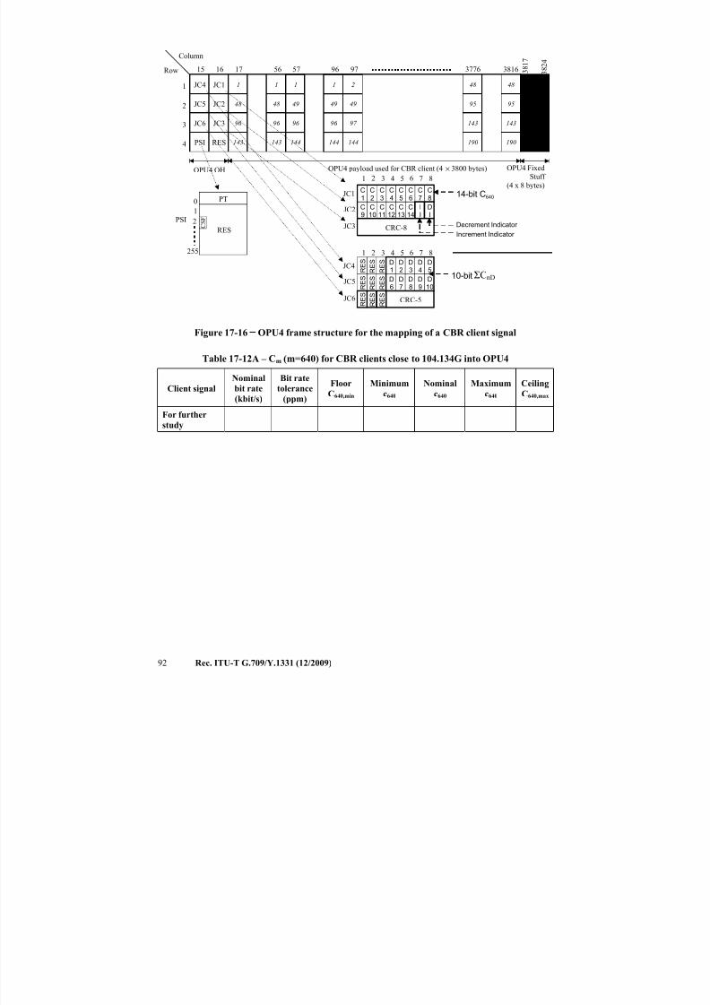
7/16/2019 G-709 ITU_T
http://slidepdf.com/reader/full/g-709-itut 100/218
92 Rec. ITU-T G.709/Y.1331 (12/2009)
Row
Column
OPU4 payload used for CBR client (4 × 3800 bytes)
JC4
JC5
JC6
PSI
1
2
3
4
3816
JC1
JC2
JC3
RES
1 6 7 82 543
JC1
16 17 5615
OPU4 OH
CRC-8
JC2
JC3
C9
C10
C11
C12
C13
C14
II
DI
C1
C2
C3
C4
C5
C6
C7
C8
Increment Indicator
Decrement Indicator
14-bit C640
1
48
96
143
1
48
96
143
48
95
143
190
48
95
143
190
377657 96
1
49
96
144
1
49
96
144
RES
255
0
1
PT
PSI C S F2
97
2
49
97
144
3 8 2 4
FixedStuff
3 8 1 7
OPU4 Fixed
Stuff
(4 x 8 bytes)
JC4
JC5
JC6
1 6 7 82 543
10-bit
CRC-5
R E SD
6D7
D8
D9
D10
R E S
R E S
R E SD
1D2
D3
D4
D5
R E S
R E S ΣCnD
R E S
R E S
R E S
Figure 17-16 − OPU4 frame structure for the mapping of a CBR client signal
Table 17-12A – Cm (m=640) for CBR clients close to 104.134G into OPU4
Client signal
Nominal
bit rate
(kbit/s)
Bit rate
tolerance
(ppm)
Floor
C640,min
Minimum
c640
Nominal
c640
Maximum
c640
Ceiling
C640,max
For further
study
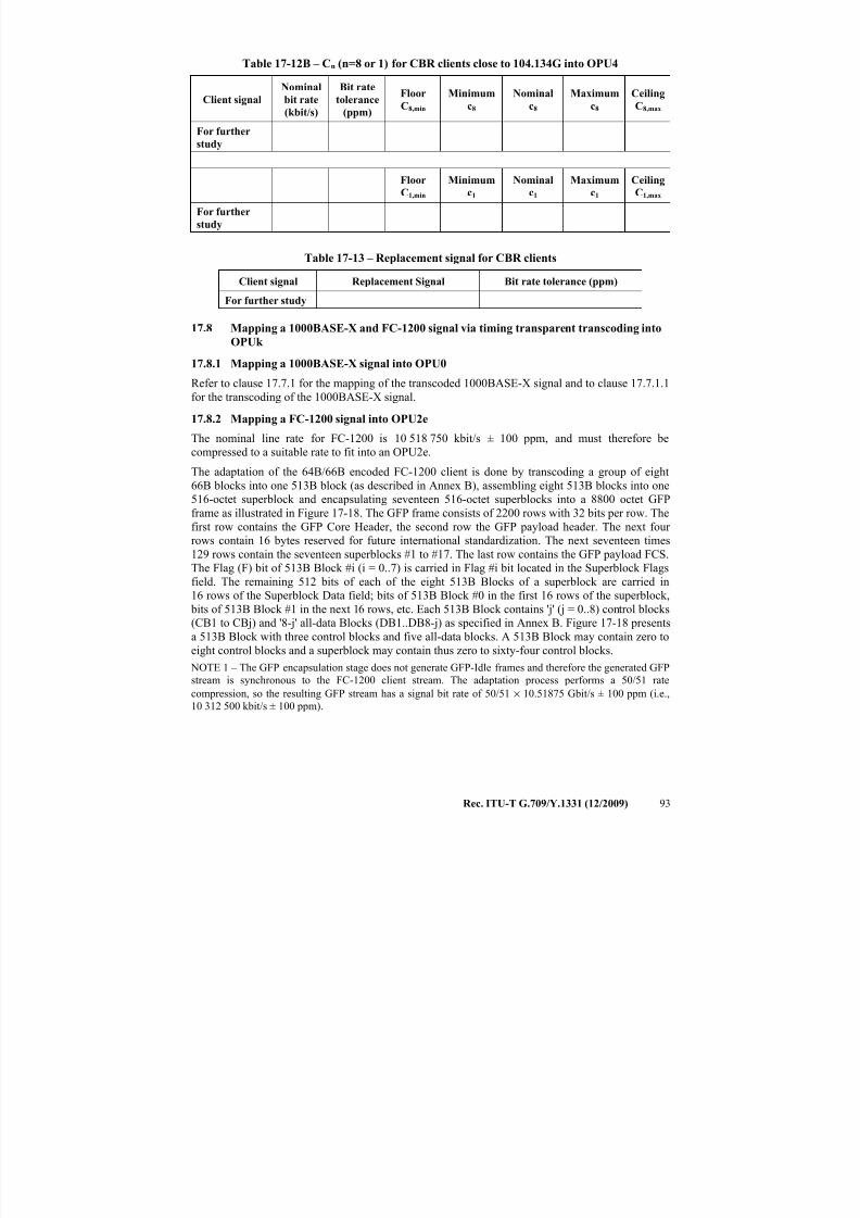
7/16/2019 G-709 ITU_T
http://slidepdf.com/reader/full/g-709-itut 101/218
Rec. ITU-T G.709/Y.1331 (12/2009) 93
Table 17-12B – Cn (n=8 or 1) for CBR clients close to 104.134G into OPU4
Client signal
Nominal
bit rate
(kbit/s)
Bit rate
tolerance
(ppm)
Floor
C8,min
Minimum
c8
Nominal
c8
Maximum
c8
Ceiling
C8,max
For further
study
Floor
C1,min
Minimum
c1
Nominal
c1
Maximum
c1
Ceiling
C1,max
For further
study
Table 17-13 – Replacement signal for CBR clients
Client signal Replacement Signal Bit rate tolerance (ppm)
For further study
17.8 Mapping a 1000BASE-X and FC-1200 signal via timing transparent transcoding into
OPUk
17.8.1 Mapping a 1000BASE-X signal into OPU0
Refer to clause 17.7.1 for the mapping of the transcoded 1000BASE-X signal and to clause 17.7.1.1
for the transcoding of the 1000BASE-X signal.
17.8.2 Mapping a FC-1200 signal into OPU2e
The nominal line rate for FC-1200 is 10 518 750 kbit/s ± 100 ppm, and must therefore becompressed to a suitable rate to fit into an OPU2e.
The adaptation of the 64B/66B encoded FC-1200 client is done by transcoding a group of eight
66B blocks into one 513B block (as described in Annex B), assembling eight 513B blocks into one
516-octet superblock and encapsulating seventeen 516-octet superblocks into a 8800 octet GFP
frame as illustrated in Figure 17-18. The GFP frame consists of 2200 rows with 32 bits per row. The
first row contains the GFP Core Header, the second row the GFP payload header. The next four
rows contain 16 bytes reserved for future international standardization. The next seventeen times
129 rows contain the seventeen superblocks #1 to #17. The last row contains the GFP payload FCS.
The Flag (F) bit of 513B Block #i (i = 0..7) is carried in Flag #i bit located in the Superblock Flags
field. The remaining 512 bits of each of the eight 513B Blocks of a superblock are carried in
16 rows of the Superblock Data field; bits of 513B Block #0 in the first 16 rows of the superblock, bits of 513B Block #1 in the next 16 rows, etc. Each 513B Block contains 'j' (j = 0..8) control blocks
(CB1 to CBj) and '8-j' all-data Blocks (DB1..DB8-j) as specified in Annex B. Figure 17-18 presents
a 513B Block with three control blocks and five all-data blocks. A 513B Block may contain zero to
eight control blocks and a superblock may contain thus zero to sixty-four control blocks.
NOTE 1 – The GFP encapsulation stage does not generate GFP-Idle frames and therefore the generated GFP
stream is synchronous to the FC-1200 client stream. The adaptation process performs a 50/51 rate
compression, so the resulting GFP stream has a signal bit rate of 50/51 × 10.51875 Gbit/s ± 100 ppm (i.e.,
10 312 500 kbit/s ± 100 ppm).
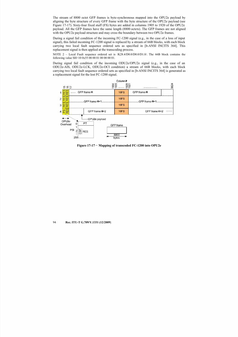
7/16/2019 G-709 ITU_T
http://slidepdf.com/reader/full/g-709-itut 102/218
94 Rec. ITU-T G.709/Y.1331 (12/2009)
The stream of 8800 octet GFP frames is byte-synchronous mapped into the OPU2e payload by
aligning the byte structure of every GFP frame with the byte structure of the OPU2e payload (see
Figure 17-17). Sixty-four fixed stuff (FS) bytes are added in columns 1905 to 1920 of the OPU2e
payload. All the GFP frames have the same length (8800 octets). The GFP frames are not aligned
with the OPU2e payload structure and may cross the boundary between two OPU2e frames.
During a signal fail condition of the incoming FC-1200 signal (e.g., in the case of a loss of input
signal), this failed incoming FC-1200 signal is replaced by a stream of 66B blocks, with each block carrying two local fault sequence ordered sets as specified in [b-ANSI INCITS 364]. This
replacement signal is then applied at the transcoding process.
NOTE 2 – Local Fault sequence ordered set is /K28.4/D0.0/D0.0/D1.0/. The 66B block contains the
following value SH=10 0x55 00 00 01 00 00 00 01.
During signal fail condition of the incoming ODU2e/OPU2e signal (e.g., in the case of an
ODU2e-AIS, ODU2e-LCK, ODU2e-OCI condition) a stream of 66B blocks, with each block
carrying two local fault sequence ordered sets as specified in [b-ANSI INCITS 364] is generated as
a replacement signal for the lost FC-1200 signal.
Figure 17-17 − Mapping of transcoded FC-1200 into OPU2e
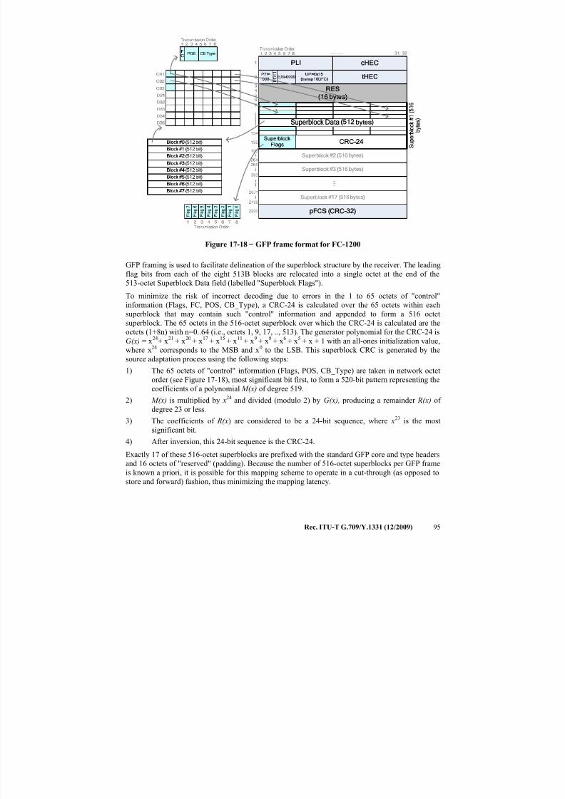
7/16/2019 G-709 ITU_T
http://slidepdf.com/reader/full/g-709-itut 103/218
Rec. ITU-T G.709/Y.1331 (12/2009) 95
Figure 17-18 − GFP frame format for FC-1200
GFP framing is used to facilitate delineation of the superblock structure by the receiver. The leading
flag bits from each of the eight 513B blocks are relocated into a single octet at the end of the
513-octet Superblock Data field (labelled "Superblock Flags").
To minimize the risk of incorrect decoding due to errors in the 1 to 65 octets of "control"
information (Flags, FC, POS, CB_Type), a CRC-24 is calculated over the 65 octets within each
superblock that may contain such "control" information and appended to form a 516 octet
superblock. The 65 octets in the 516-octet superblock over which the CRC-24 is calculated are the
octets (1+8n) with n=0..64 (i.e., octets 1, 9, 17, .., 513). The generator polynomial for the CRC-24 is
G(x) = x24+ x21 + x20 + x17 + x15 + x11 + x9 + x8 + x6 + x5 + x + 1 with an all-ones initialization value,
where x24 corresponds to the MSB and x0 to the LSB. This superblock CRC is generated by the
source adaptation process using the following steps:
1) The 65 octets of "control" information (Flags, POS, CB_Type) are taken in network octet
order (see Figure 17-18), most significant bit first, to form a 520-bit pattern representing the
coefficients of a polynomial M(x) of degree 519.
2) M(x) is multiplied by x24 and divided (modulo 2) by G(x), producing a remainder R(x) of
degree 23 or less.
3) The coefficients of R(x) are considered to be a 24-bit sequence, where x23 is the most
significant bit.
4) After inversion, this 24-bit sequence is the CRC-24.
Exactly 17 of these 516-octet superblocks are prefixed with the standard GFP core and type headers
and 16 octets of "reserved" (padding). Because the number of 516-octet superblocks per GFP frame
is known a priori, it is possible for this mapping scheme to operate in a cut-through (as opposed to
store and forward) fashion, thus minimizing the mapping latency.
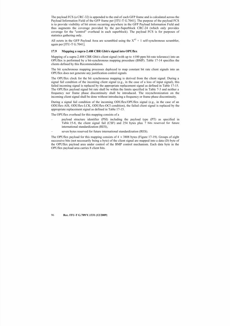
7/16/2019 G-709 ITU_T
http://slidepdf.com/reader/full/g-709-itut 104/218
96 Rec. ITU-T G.709/Y.1331 (12/2009)
The payload FCS (a CRC-32) is appended to the end of each GFP frame and is calculated across the
Payload Information Field of the GFP frame per [ITU-T G.7041]. The purpose of the payload FCS
is to provide visibility of bit errors occurring anywhere in the GFP Payload Information Field and
thus augments the coverage provided by the per-Superblock CRC-24 (which only provides
coverage for the "control" overhead in each superblock). The payload FCS is for purposes of
statistics gathering only.
All octets in the GFP Payload Area are scrambled using the X43 + 1 self-synchronous scrambler,again per [ITU-T G.7041].
17.9 Mapping a supra-2.488 CBR Gbit/s signal into OPUflex
Mapping of a supra-2.488 CBR Gbit/s client signal (with up to ±100 ppm bit-rate tolerance) into an
OPUflex is performed by a bit-synchronous mapping procedure (BMP). Table 17-14 specifies the
clients defined by this Recommendation.
The bit synchronous mapping processes deployed to map constant bit rate client signals into an
OPUflex does not generate any justification control signals.
The OPUflex clock for the bit synchronous mapping is derived from the client signal. During asignal fail condition of the incoming client signal (e.g., in the case of a loss of input signal), this
failed incoming signal is replaced by the appropriate replacement signal as defined in Table 17-15.
The OPUflex payload signal bit rate shall be within the limits specified in Table 7-3 and neither a
frequency nor frame phase discontinuity shall be introduced. The resynchronization on the
incoming client signal shall be done without introducing a frequency or frame phase discontinuity.
During a signal fail condition of the incoming ODUflex/OPUflex signal (e.g., in the case of an
ODUflex-AIS, ODUflex-LCK, ODUflex-OCI condition), the failed client signal is replaced by the
appropriate replacement signal as defined in Table 17-15.
The OPUflex overhead for this mapping consists of a
– payload structure identifier (PSI) including the payload type (PT) as specified inTable 15-8, the client signal fail (CSF) and 254 bytes plus 7 bits reserved for future
international standardization (RES),
– seven bytes reserved for future international standardization (RES).
The OPUflex payload for this mapping consists of 4 × 3808 bytes (Figure 17-19). Groups of eight
successive bits (not necessarily being a byte) of the client signal are mapped into a data (D) byte of
the OPUflex payload area under control of the BMP control mechanism. Each data byte in the
OPUflex payload area carries 8 client bits.
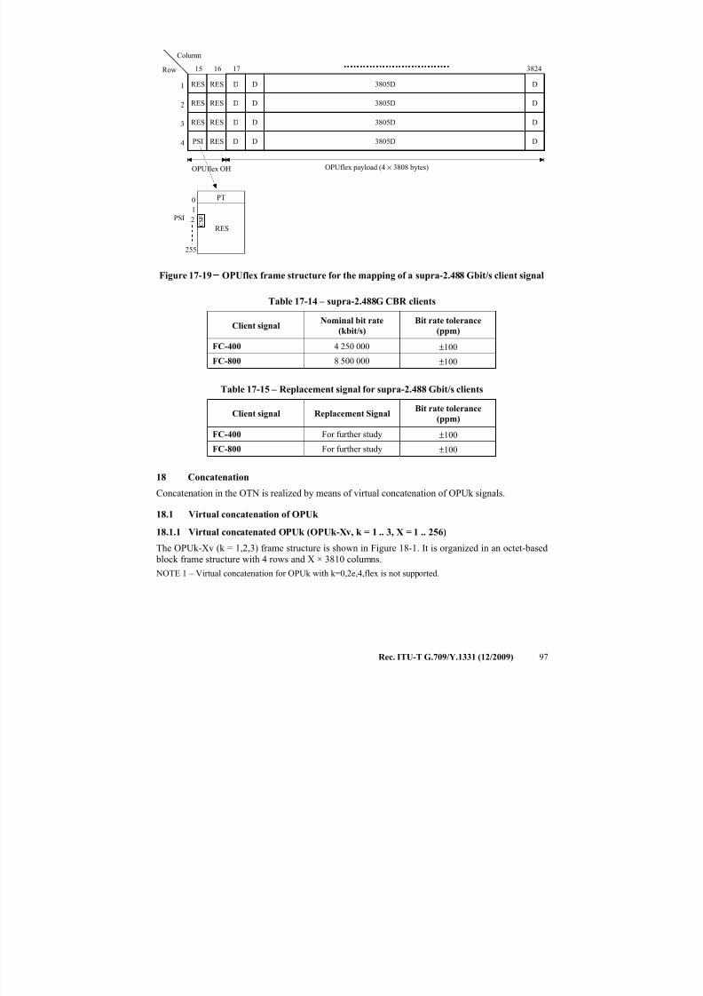
7/16/2019 G-709 ITU_T
http://slidepdf.com/reader/full/g-709-itut 105/218
Rec. ITU-T G.709/Y.1331 (12/2009) 97
Row
Column
OPUflex payload (4 × 3808 bytes)
RES
RES
RES
PSI
1
2
3
4
3824
RES
RES
RES
RES
16 1715
OPUflex OH
RES
255
0
1
PT
PSI C S F2
D
D
D
D
D
D
D
D
D
D
D
D
3805D
3805D
3805D
3805D
Figure 17-19 − OPUflex frame structure for the mapping of a supra-2.488 Gbit/s client signal
Table 17-14 – supra-2.488G CBR clients
Client signalNominal bit rate
(kbit/s)
Bit rate tolerance
(ppm)
FC-400 4 250 000 ±100
FC-800 8 500 000 ±100
Table 17-15 – Replacement signal for supra-2.488 Gbit/s clients
Client signal Replacement SignalBit rate tolerance
(ppm)
FC-400 For further study ±100
FC-800 For further study ±100
18 Concatenation
Concatenation in the OTN is realized by means of virtual concatenation of OPUk signals.
18.1 Virtual concatenation of OPUk
18.1.1 Virtual concatenated OPUk (OPUk-Xv, k = 1 .. 3, X = 1 .. 256)
The OPUk-Xv (k = 1,2,3) frame structure is shown in Figure 18-1. It is organized in an octet-based
block frame structure with 4 rows and X × 3810 columns.
NOTE 1 – Virtual concatenation for OPUk with k=0,2e,4,flex is not supported.
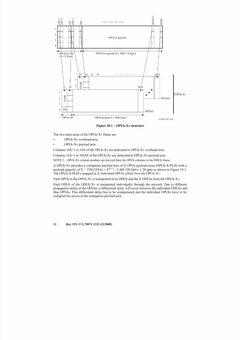
7/16/2019 G-709 ITU_T
http://slidepdf.com/reader/full/g-709-itut 106/218
98 Rec. ITU-T G.709/Y.1331 (12/2009)
G.709/Y.1331_F18-1
1 4 X + 1
1 4 X + 2
1 6 X
3 8 2 4 X
1
2
3
4
OPUk-Xv payload (4 × 3808 × X bytes)
1
2
3
4
OPUk payload (4 × 3808 bytes)OPUk OH
PSIOPUk#1
OPUk#X
OPUk-Xv
V C O H
1 5 X
3 8 2 3 X + 1
3824
OPUk-X payload
16 17 38241815
1
2
V C O H
1 5 X + 1
15 16
OPUk-Xv OH(8 × X bytes)
Figure 18-1 – OPUk-Xv structure
The two main areas of the OPUk-Xv frame are:
• OPUk-Xv overhead area;
• OPUk-Xv payload area.
Columns 14X+1 to 16X of the OPUk-Xv are dedicated to OPUk-Xv overhead area.
Columns 16X+1 to 3824X of the OPUk-Xv are dedicated to OPUk-Xv payload area.
NOTE 2 – OPUk-Xv column numbers are derived from the OPUk columns in the ODUk frame.
A OPUk-Xv provides a contiguous payload area of X OPUk payload areas (OPUk-X-PLD) with a payload capacity of X × 238/(239-k) × 4(k–1) × 2 488 320 kbit/s ± 20 ppm as shown in Figure 18-1.
The OPUk-X-PLD is mapped in X individual OPUks which form the OPUk-Xv.
Each OPUk in the OPUk-Xv is transported in an ODUk and the X ODUks form the ODUk-Xv.
Each ODUk of the ODUk-Xv is transported individually through the network. Due to different
propagation delay of the ODUks, a differential delay will occur between the individual ODUks and
thus OPUks. This differential delay has to be compensated and the individual OPUks have to be
realigned for access to the contiguous payload area.
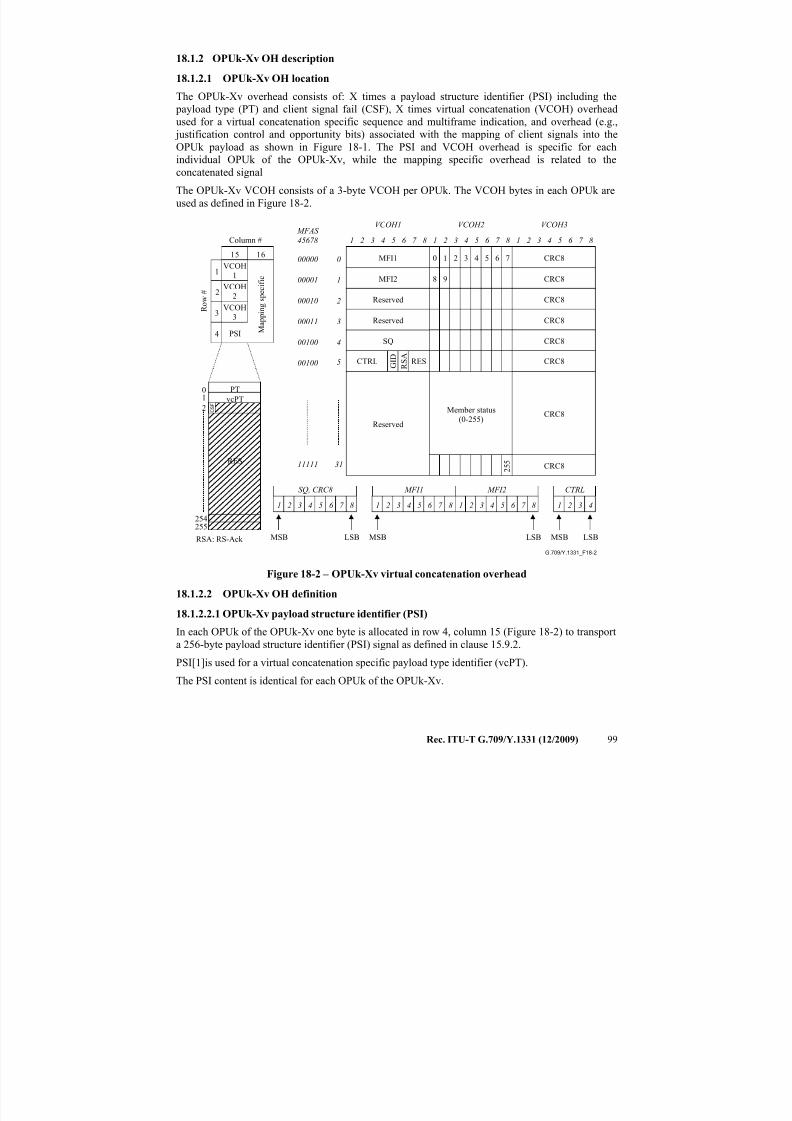
7/16/2019 G-709 ITU_T
http://slidepdf.com/reader/full/g-709-itut 107/218
Rec. ITU-T G.709/Y.1331 (12/2009) 99
18.1.2 OPUk-Xv OH description
18.1.2.1 OPUk-Xv OH location
The OPUk-Xv overhead consists of: X times a payload structure identifier (PSI) including the
payload type (PT) and client signal fail (CSF), X times virtual concatenation (VCOH) overhead
used for a virtual concatenation specific sequence and multiframe indication, and overhead (e.g.,
justification control and opportunity bits) associated with the mapping of client signals into theOPUk payload as shown in Figure 18-1. The PSI and VCOH overhead is specific for each
individual OPUk of the OPUk-Xv, while the mapping specific overhead is related to the
concatenated signal
The OPUk-Xv VCOH consists of a 3-byte VCOH per OPUk. The VCOH bytes in each OPUk are
used as defined in Figure 18-2.
G.709/Y.1331_F18-2
1
2
3
4
Column #
PSI
15 16
R o w #
RES
255254
01
2
PT
VCOH
1
VCOH
3
VCOH
2
1 2 3 4 5 6 7 8 1 2 3 4 5 6 7 8 1 2 3 4 5 6 7 8
CTRL G I D
R S A
CRC8
RES
0 1
2 5 5
2 3 4 5 6 7
8 9
0
1
2
Member status(0-255)
VCOH1 VCOH2 VCOH3
MFI1
MFI2
SQ
Reserved
Reserved
Reserved
3
4
5
00000
00001
00010
00011
00100
00100
MFAS
45678
CRC8
CRC8
CRC8
CRC8
CRC8
CRC8
CRC8
vcPT
M a p p i n g s p e c i f i c
MSB LSBRSA: RS-Ack
1 2 3 4 5 6 7 8
MSB LSB MSB LSB
3111111
1 2 3 4 5 6 7 8 1 2 3 4 5 6 7 8
MFI1 MFI2SQ, CRC8
1 2 3 4
CTRL
C S
F
Figure 18-2 – OPUk-Xv virtual concatenation overhead
18.1.2.2 OPUk-Xv OH definition
18.1.2.2.1 OPUk-Xv payload structure identifier (PSI)
In each OPUk of the OPUk-Xv one byte is allocated in row 4, column 15 (Figure 18-2) to transport
a 256-byte payload structure identifier (PSI) signal as defined in clause 15.9.2.
PSI[1]is used for a virtual concatenation specific payload type identifier (vcPT).
The PSI content is identical for each OPUk of the OPUk-Xv.
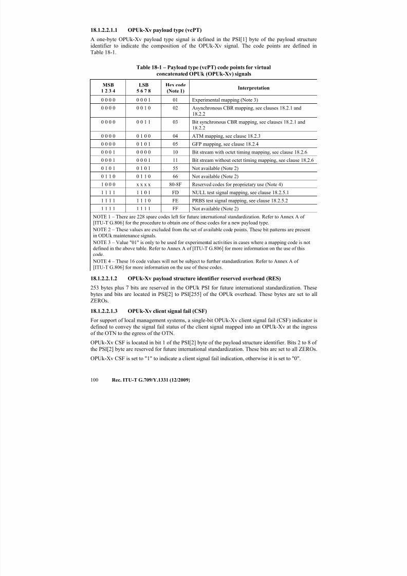
7/16/2019 G-709 ITU_T
http://slidepdf.com/reader/full/g-709-itut 108/218
100 Rec. ITU-T G.709/Y.1331 (12/2009)
18.1.2.2.1.1 OPUk-Xv payload type (vcPT)
A one-byte OPUk-Xv payload type signal is defined in the PSI[1] byte of the payload structure
identifier to indicate the composition of the OPUk-Xv signal. The code points are defined in
Table 18-1.
Table 18-1 – Payload type (vcPT) code points for virtualconcatenated OPUk (OPUk-Xv) signals
MSB
1 2 3 4
LSB
5 6 7 8
Hex code
(Note 1)Interpretation
0 0 0 0 0 0 0 1 01 Experimental mapping (Note 3)
0 0 0 0 0 0 1 0 02 Asynchronous CBR mapping, see clauses 18.2.1 and
18.2.2
0 0 0 0 0 0 1 1 03 Bit synchronous CBR mapping, see clauses 18.2.1 and
18.2.2
0 0 0 0 0 1 0 0 04 ATM mapping, see clause 18.2.3
0 0 0 0 0 1 0 1 05 GFP mapping, see clause 18.2.4
0 0 0 1 0 0 0 0 10 Bit stream with octet timing mapping, see clause 18.2.6
0 0 0 1 0 0 0 1 11 Bit stream without octet timing mapping, see clause 18.2.6
0 1 0 1 0 1 0 1 55 Not available (Note 2)
0 1 1 0 0 1 1 0 66 Not available (Note 2)
1 0 0 0 x x x x 80-8F Reserved codes for proprietary use (Note 4)
1 1 1 1 1 1 0 1 FD NULL test signal mapping, see clause 18.2.5.1
1 1 1 1 1 1 1 0 FE PRBS test signal mapping, see clause 18.2.5.2
1 1 1 1 1 1 1 1 FF Not available (Note 2) NOTE 1 – There are 228 spare codes left for future international standardization. Refer to Annex A of
[ITU-T G.806] for the procedure to obtain one of these codes for a new payload type.
NOTE 2 – These values are excluded from the set of available code points. These bit patterns are present
in ODUk maintenance signals.
NOTE 3 – Value "01" is only to be used for experimental activities in cases where a mapping code is not
defined in the above table. Refer to Annex A of [ITU-T G.806] for more information on the use of this
code.
NOTE 4 – These 16 code values will not be subject to further standardization. Refer to Annex A of
[ITU-T G.806] for more information on the use of these codes.
18.1.2.2.1.2 OPUk-Xv payload structure identifier reserved overhead (RES)253 bytes plus 7 bits are reserved in the OPUk PSI for future international standardization. These
bytes and bits are located in PSI[2] to PSI[255] of the OPUk overhead. These bytes are set to all
ZEROs.
18.1.2.2.1.3 OPUk-Xv client signal fail (CSF)
For support of local management systems, a single-bit OPUk-Xv client signal fail (CSF) indicator is
defined to convey the signal fail status of the client signal mapped into an OPUk-Xv at the ingress
of the OTN to the egress of the OTN.
OPUk-Xv CSF is located in bit 1 of the PSI[2] byte of the payload structure identifier. Bits 2 to 8 of
the PSI[2] byte are reserved for future international standardization. These bits are set to all ZEROs.
OPUk-Xv CSF is set to "1" to indicate a client signal fail indication, otherwise it is set to "0".
7/16/2019 G-709 ITU_T
http://slidepdf.com/reader/full/g-709-itut 109/218
Rec. ITU-T G.709/Y.1331 (12/2009) 101
NOTE – Equipment designed prior to this revision of the Recommendation will generate a "0" in the
OPUk-Xv CSF and will ignore any value in OPUk CSF.
18.1.2.2.2 OPUk-Xv virtual concatenation overhead (VCOH1/2/3)
Three bytes per individual OPUk of the OPUk-Xv are used to transport a 8 × 3 byte × 32 frame
structure for virtual concatenation specific overhead. These bytes are located in rows 1, 2 and 3 of
column 15 as shown in Figure 18-2.The structure is aligned with the ODUk multiframe and locked to bits 4, 5, 6, 7 and 8 of the MFAS.
The structure is repeated 8 times in the 256-frame multiframe.
The structure is used to transport multiframe sequences and LCAS control overhead.
18.1.2.2.2.1 OPUk-Xv virtual concatenation multiframe indicator (MFI1, MFI2)
A two-stage multiframe is introduced to cover differential delay measurement (between the member
signals within the virtual concatenated group) and compensation (of those differential delays) by the
realignment process within the receiver.
The first stage uses MFAS in the frame alignment overhead area for the 8-bit multiframe indicator.
MFAS is incremented every ODUk frame and counts from 0 to 255.
The second stage uses the MFI1 and MFI2 overhead bytes in the VCOH. They form a 16-bit
multiframe counter with the MSBs in MFI1 and the LSBs in MFI2.
MFI1 is located in VCOH1[0] and MFI2 in VCOH1[1].
The multiframe counter of the second stage counts from 0 to 65535 and is incremented at the start
of each multiframe of the first stage (MFAS = 0).
The resulting overall multiframe (a combination of 1st multiframe and 2nd multiframe counter) is
16 777 216 ODUk frames long.
At the start of the OPUk-Xv the multiframe sequence of all individual OPUks of the OPUk-Xv isidentical.
The realignment process has to be able to compensate a differential delay of at least 125 µs.
18.1.2.2.2.2 OPUk-Xv sequence indicator (SQ)
The sequence indicator SQ identifies the sequence/order in which the individual OPUks of the
OPUk-Xv are combined to form the contiguous OPUk-X-PLD as shown in Figure 18-1.
The 8-bit sequence number SQ (which supports values of X up to 256) is transported in VCOH1[4].
Bit 1 of VCOH1[4] is the MSB, bit 8 is the LSB.
Each OPUk of an OPUk-Xv has a fixed unique sequence number in the range of 0 to (X–1). The
OPUk transporting the first time slot of the OPUk-Xv has the sequence number 0, the OPUk transporting the second time slot has the sequence number 1 and so on up to the OPUk transporting
time slot X of the OPUk-Xv with the sequence number (X–1).
For applications requiring fixed bandwidth the sequence number is fixed assigned and not
configurable. This allows the constitution of the OPUk-Xv either to be checked without using the
trace, or to be transported via a number of ODUk signals which have their trail termination
functions being part of an ODUk trail termination function resource group.
Refer to [ITU-T G.7042] for the use and operation.
18.1.2.2.2.3 OPUk-Xv LCAS control words (CTRL)
The LCAS control word (CTRL) is located in bits 1 to 4 of VCOH1[5]. Bit 1 of VCOH1[5] is the
MSB, bit 4 is the LSB.
7/16/2019 G-709 ITU_T
http://slidepdf.com/reader/full/g-709-itut 110/218
102 Rec. ITU-T G.709/Y.1331 (12/2009)
Refer to [ITU-T G.7042] for the LCAS control commands, their coding and operation.
18.1.2.2.2.4 OPUk-Xv LCAS member status field (MST)
The LCAS member status field (MST) reports the status of the individual OPUks of the OPUk-Xv.
One bit is used per OPUk to report the status from sink to source. VCOH2[0] to VCOH2[31] are
used as shown in Figure 18-2. Refer to [ITU-T G.7042] for coding and operation.
The status of all members (256) is transferred in 1567 μs (k = 1), 390 μs (k = 2) and 97 μs (k = 3).
18.1.2.2.2.5 OPUk-Xv LCAS group identification (GID)
The LCAS group identification (GID) provides the receiver with a means of verifying that all the
arriving channels originated from one transmitter. Refer to [ITU-T G.7042] for coding and
operation.
Bit 5 of VCOH1[5] is used for the GID.
18.1.2.2.2.6 OPUk-Xv LCAS re-sequence acknowledge (RS-Ack)
Re-sequence acknowledge, an indication from sink to source that a re-sequence, a sequence
increase or a sequence decrease has been detected. Refer to [ITU-T G.7042] for coding and
operation.
Bit 6 of VCOH1[5] is used for the RS-Ack.
18.1.2.2.2.7 OPUk-Xv LCAS cyclic redundancy check (CRC)
An 8-bit CRC check for fast acceptance of VirtConc LCAS OH is provided. The CRC-8 is
calculated over VCOH1 and VCOH2 on a frame per frame basis and inserted into VCOH3. The
CRC_8 Polynomial is x8 + x3 + x2 + 1. Refer to [ITU-T G.7042] for operation.
18.1.2.2.2.8 OPUk-Xv VCOH reserved overhead
The reserved VCOH is set to all-0s.
18.1.2.2.3 OPUk mapping specific overhead
X times four bytes are reserved in the OPUk overhead for mapping specific overhead. These bytes
are located in columns 15X+1 to 16X.
The use of these bytes depends on the specific client signal mapping (defined in clause 18.2).
18.2 Mapping of client signals
18.2.1 Mapping of CBR signals (e.g., STM-64/256) into OPUk-4v
Mapping of a CBR signal (with up to ±20 ppm bit-rate tolerance) into an OPUk-4v may be performed according to two different modes (asynchronous and bit synchronous) based on one
generic OPUk-4v frame structure (see Figure 18-3).
NOTE 1 – Examples of such signals are STM-64 and STM-256.
NOTE 2 – The maximum bit-rate tolerance between OPUk-4v and the client signal clock, which can be
accommodated by this mapping scheme, is ±65 ppm. With a bit-rate tolerance of ±20 ppm for the OPUk-4v
clock, the client signal's bit-rate tolerance can be ±45 ppm.
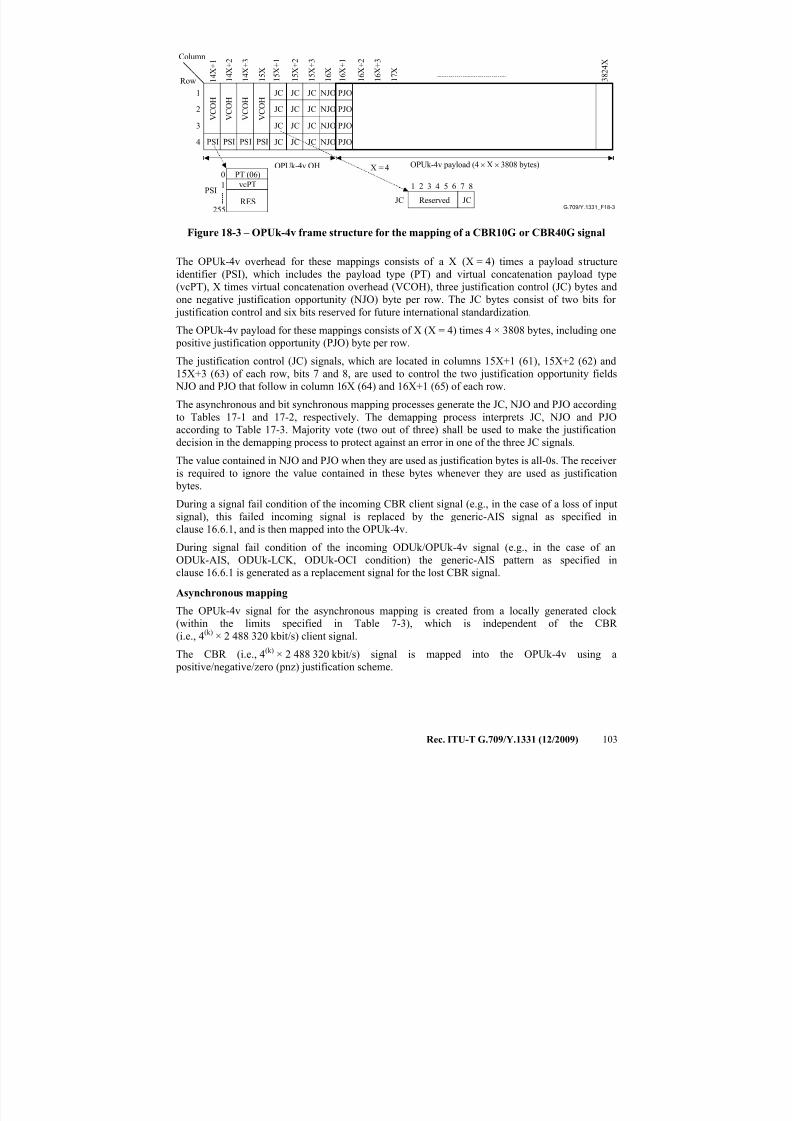
7/16/2019 G-709 ITU_T
http://slidepdf.com/reader/full/g-709-itut 111/218
Rec. ITU-T G.709/Y.1331 (12/2009) 103
G.709/Y.1331_F18-3
1
2
3
4
1 4 X + 2
3 8 2 4 X
Row
Column
OPUk-4v payload (4 × X × 3808 bytes)
1 4 X + 1
NJO
PSI
OPUk-4v OH
PJO
JCReserved
1 6 7 82 543
JCRES255
0
1
PT (06)
PSI
JC
JC
JC NJO
NJO
NJO
PJO
PJO
PJO
V C O H
PSI PSI PSI
V C O H
V C O H
V C O H
1 4 X + 3
1 5 X
1 5 X + 2
1 5 X + 1
1 5 X + 3
1 6 X
1 6 X + 2
1 6 X + 1
1 6 X + 3
1 7 X
X = 4
JC
JC
JC
JC
JC
JC
JC
JC
JC
vcPT
Figure 18-3 – OPUk-4v frame structure for the mapping of a CBR10G or CBR40G signal
The OPUk-4v overhead for these mappings consists of a X (X = 4) times a payload structure
identifier (PSI), which includes the payload type (PT) and virtual concatenation payload type(vcPT), X times virtual concatenation overhead (VCOH), three justification control (JC) bytes and
one negative justification opportunity (NJO) byte per row. The JC bytes consist of two bits for
justification control and six bits reserved for future international standardization.
The OPUk-4v payload for these mappings consists of X (X = 4) times 4 × 3808 bytes, including one
positive justification opportunity (PJO) byte per row.
The justification control (JC) signals, which are located in columns 15X+1 (61), 15X+2 (62) and
15X+3 (63) of each row, bits 7 and 8, are used to control the two justification opportunity fields
NJO and PJO that follow in column 16X (64) and 16X+1 (65) of each row.
The asynchronous and bit synchronous mapping processes generate the JC, NJO and PJO accordingto Tables 17-1 and 17-2, respectively. The demapping process interprets JC, NJO and PJO
according to Table 17-3. Majority vote (two out of three) shall be used to make the justification
decision in the demapping process to protect against an error in one of the three JC signals.
The value contained in NJO and PJO when they are used as justification bytes is all-0s. The receiver
is required to ignore the value contained in these bytes whenever they are used as justification
bytes.
During a signal fail condition of the incoming CBR client signal (e.g., in the case of a loss of input
signal), this failed incoming signal is replaced by the generic-AIS signal as specified in
clause 16.6.1, and is then mapped into the OPUk-4v.
During signal fail condition of the incoming ODUk/OPUk-4v signal (e.g., in the case of anODUk-AIS, ODUk-LCK, ODUk-OCI condition) the generic-AIS pattern as specified in
clause 16.6.1 is generated as a replacement signal for the lost CBR signal.
Asynchronous mapping
The OPUk-4v signal for the asynchronous mapping is created from a locally generated clock
(within the limits specified in Table 7-3), which is independent of the CBR
(i.e., 4(k) × 2 488 320 kbit/s) client signal.
The CBR (i.e., 4(k) × 2 488 320 kbit/s) signal is mapped into the OPUk-4v using a
positive/negative/zero (pnz) justification scheme.
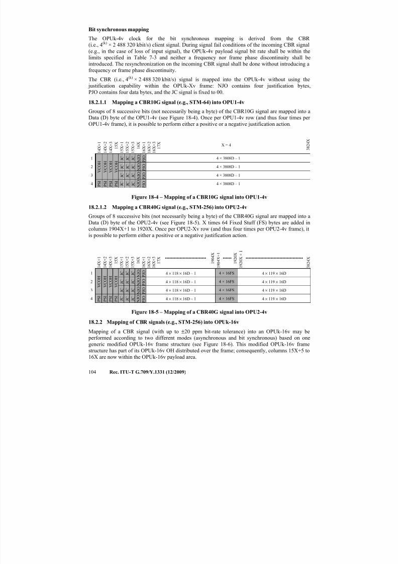
7/16/2019 G-709 ITU_T
http://slidepdf.com/reader/full/g-709-itut 112/218
104 Rec. ITU-T G.709/Y.1331 (12/2009)
Bit synchronous mapping
The OPUk-4v clock for the bit synchronous mapping is derived from the CBR
(i.e., 4(k) × 2 488 320 kbit/s) client signal. During signal fail conditions of the incoming CBR signal
(e.g., in the case of loss of input signal), the OPUk-4v payload signal bit rate shall be within the
limits specified in Table 7-3 and neither a frequency nor frame phase discontinuity shall be
introduced. The resynchronization on the incoming CBR signal shall be done without introducing a
frequency or frame phase discontinuity.
The CBR (i.e., 4(k) × 2 488 320 kbit/s) signal is mapped into the OPUk-4v without using the
justification capability within the OPUk-Xv frame: NJO contains four justification bytes,
PJO contains four data bytes, and the JC signal is fixed to 00.
18.2.1.1 Mapping a CBR10G signal (e.g., STM-64) into OPU1-4v
Groups of 8 successive bits (not necessarily being a byte) of the CBR10G signal are mapped into a
Data (D) byte of the OPU1-4v (see Figure 18-4). Once per OPU1-4v row (and thus four times per
OPU1-4v frame), it is possible to perform either a positive or a negative justification action.
1 4 X + 1
1 4 X + 2
1 4 X + 3
1 5 X
1 5 X + 1
1 5 X + 2
1 5 X + 3
1 6 X
1 6 X + 1
1 6 X + 2
1 6 X + 3
1 7 X X = 4
3 8 2 4 X
1
V C O H
V C O H
V C O H
V C O H J C J C J C
N J O P J O 4 × 3808D – 1
2 J C J C J C N J O P J O 4 × 3808D – 1
3 J C J C J C N J O P J O 4 × 3808D – 1
4 P S I P S I P S I P S I J C J C J C N
J O
P J O 4 × 3808D – 1
Figure 18-4 – Mapping of a CBR10G signal into OPU1-4v
18.2.1.2 Mapping a CBR40G signal (e.g., STM-256) into OPU2-4v
Groups of 8 successive bits (not necessarily being a byte) of the CBR40G signal are mapped into a
Data (D) byte of the OPU2-4v (see Figure 18-5). X times 64 Fixed Stuff (FS) bytes are added in
columns 1904X+1 to 1920X. Once per OPU2-Xv row (and thus four times per OPU2-4v frame), it
is possible to perform either a positive or a negative justification action.
1 4 X + 1
1 4 X + 2
1 4 X + 3
1 5 X
1 5 X + 1
1 5 X + 2
1 5 X + 3
1 6 X
1 6 X + 1
1 6 X + 2
1 6 X + 3
1 7 X ••••••••••••••••••••••••••••
1 9 0 4 X
1 9 0 4 X + 1
••••••
1 9 2 0 X
1 9 2 0 X + 1
•••••••••••••••••••••••••••••••••••••••
3 8 2 4 X
1
V C O H
V C O H
V C O H
V C O H J C J C J C N J
O
P J O
4 × 118 × 16D – 1 4 × 16FS 4 × 119 × 16D
2 J C J C J C N J O P J O 4 × 118 × 16D – 1 4 × 16FS 4 × 119 × 16D
3 J C J C J C N J O P J O 4 × 118 × 16D – 1 4 × 16FS 4 × 119 × 16D
4 P S I P S I P S I P S I J C J C J C N
J O
P J O 4 × 118 × 16D – 1 4 × 16FS 4 × 119 × 16D
Figure 18-5 – Mapping of a CBR40G signal into OPU2-4v
18.2.2 Mapping of CBR signals (e.g., STM-256) into OPUk-16v
Mapping of a CBR signal (with up to ±20 ppm bit-rate tolerance) into an OPUk-16v may be
performed according to two different modes (asynchronous and bit synchronous) based on one
generic modified OPUk-16v frame structure (see Figure 18-6). This modified OPUk-16v framestructure has part of its OPUk-16v OH distributed over the frame; consequently, columns 15X+5 to
16X are now within the OPUk-16v payload area.
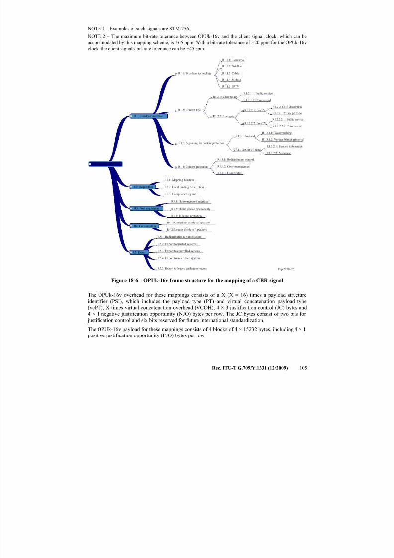
7/16/2019 G-709 ITU_T
http://slidepdf.com/reader/full/g-709-itut 113/218
Rec. ITU-T G.709/Y.1331 (12/2009) 105
NOTE 1 – Examples of such signals are STM-256.
NOTE 2 – The maximum bit-rate tolerance between OPUk-16v and the client signal clock, which can be
accommodated by this mapping scheme, is ±65 ppm. With a bit-rate tolerance of ±20 ppm for the OPUk-16v
clock, the client signal's bit-rate tolerance can be ±45 ppm.
Rep 2070-02
R1.1.1: Terrestrial
R1.1.2: Satellite
R1.1.3: Cable
R1.1.4: Mobile
R1.1.5: IPTV
R1.1: Broadcast technology
R1.2: Content type
R1.2.1: Clear-to-air
R1.2.2: Encrypted
R1.2.1.1: Public service
R1.2.1.2: Comm ercial
R1.2.2.1: PayTV
R1.2.2.2: FreeTV
R1.2.2.1.1: Subscription
R1.2.2.1.2: Pay per view
R1.2.2.2.1: Public service
R1.2.2.2.2: Commercial
R1.3.1: In-band
R1.3.1.1: Watermarking
R1.3.1.2: Vertical blanking interval
R1.3.2: Out-of-bandR1.3.2.1: Service information
R1.3.2.2: Metadata
R1.3: Signalling for content protection
R1.4: Content protection
R1.4.1: Redistribution control
R1.4.2: Copy management
R1.4.3: Usage rules
R2.1: Mapping function
R2.2: Local binding / encryption
R2.3: Compliance regime
R3.1: Home network interface
R3.2: Home device functionality
R3.3: In-home protection
R4.1: Compliant displays / speakers
R4.2: Legacy displays / speakers
R5.1: Redistribution to s ame system
R5.2: Export to trusted systems
R5.3: Export to controlled systems
R5.4: Export to unstrusted systems
R5.5: Export to legacy analogue systems
R1: Broadcast interface
Reference points
R2: Acquisition
R3: Post acquisition
R4: Consumption
R5: Export
Figure 18-6 – OPUk-16v frame structure for the mapping of a CBR signal
The OPUk-16v overhead for these mappings consists of a X (X = 16) times a payload structure
identifier (PSI), which includes the payload type (PT) and virtual concatenation payload type
(vcPT), X times virtual concatenation overhead (VCOH), 4 × 3 justification control (JC) bytes and
4 × 1 negative justification opportunity (NJO) bytes per row. The JC bytes consist of two bits for
justification control and six bits reserved for future international standardization.
The OPUk-16v payload for these mappings consists of 4 blocks of 4 × 15232 bytes, including 4 × 1
positive justification opportunity (PJO) bytes per row.
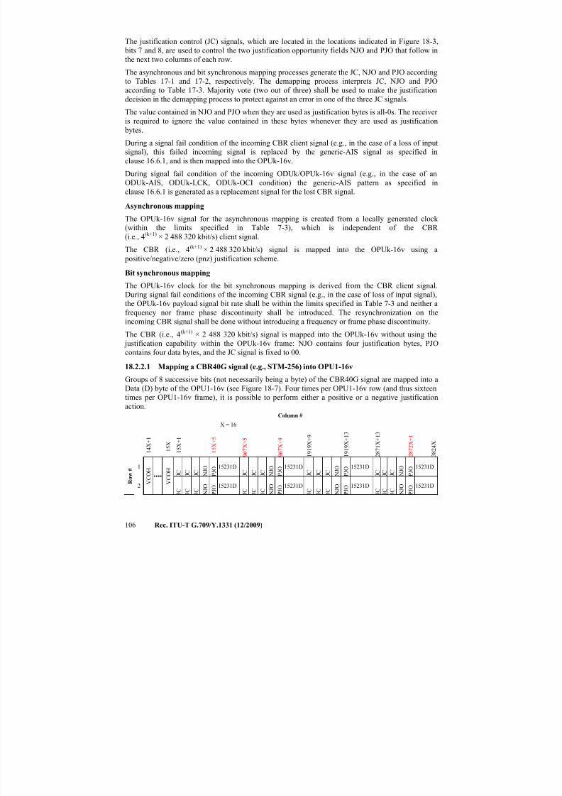
7/16/2019 G-709 ITU_T
http://slidepdf.com/reader/full/g-709-itut 114/218
106 Rec. ITU-T G.709/Y.1331 (12/2009)
The justification control (JC) signals, which are located in the locations indicated in Figure 18-3,
bits 7 and 8, are used to control the two justification opportunity fields NJO and PJO that follow in
the next two columns of each row.
The asynchronous and bit synchronous mapping processes generate the JC, NJO and PJO according
to Tables 17-1 and 17-2, respectively. The demapping process interprets JC, NJO and PJO
according to Table 17-3. Majority vote (two out of three) shall be used to make the justification
decision in the demapping process to protect against an error in one of the three JC signals.
The value contained in NJO and PJO when they are used as justification bytes is all-0s. The receiver
is required to ignore the value contained in these bytes whenever they are used as justification
bytes.
During a signal fail condition of the incoming CBR client signal (e.g., in the case of a loss of input
signal), this failed incoming signal is replaced by the generic-AIS signal as specified in
clause 16.6.1, and is then mapped into the OPUk-16v.
During signal fail condition of the incoming ODUk/OPUk-16v signal (e.g., in the case of an
ODUk-AIS, ODUk-LCK, ODUk-OCI condition) the generic-AIS pattern as specified in
clause 16.6.1 is generated as a replacement signal for the lost CBR signal.
Asynchronous mapping
The OPUk-16v signal for the asynchronous mapping is created from a locally generated clock
(within the limits specified in Table 7-3), which is independent of the CBR
(i.e., 4(k+1) × 2 488 320 kbit/s) client signal.
The CBR (i.e., 4(k+1) × 2 488 320 kbit/s) signal is mapped into the OPUk-16v using a
positive/negative/zero (pnz) justification scheme.
Bit synchronous mapping
The OPUk-16v clock for the bit synchronous mapping is derived from the CBR client signal.
During signal fail conditions of the incoming CBR signal (e.g., in the case of loss of input signal),
the OPUk-16v payload signal bit rate shall be within the limits specified in Table 7-3 and neither a
frequency nor frame phase discontinuity shall be introduced. The resynchronization on the
incoming CBR signal shall be done without introducing a frequency or frame phase discontinuity.
The CBR (i.e., 4(k+1) × 2 488 320 kbit/s) signal is mapped into the OPUk-16v without using the
justification capability within the OPUk-16v frame: NJO contains four justification bytes, PJO
contains four data bytes, and the JC signal is fixed to 00.
18.2.2.1 Mapping a CBR40G signal (e.g., STM-256) into OPU1-16v
Groups of 8 successive bits (not necessarily being a byte) of the CBR40G signal are mapped into a
Data (D) byte of the OPU1-16v (see Figure 18-7). Four times per OPU1-16v row (and thus sixteentimes per OPU1-16v frame), it is possible to perform either a positive or a negative justification
action.Column #
1 4 X + 1
1 5 X
1 5 X + 1
1 5 X + 5
X = 16
9 6 7 X + 5
9 6 7 X + 9
1 9 1 9 X + 9
1 9 1 9 X + 1 3
2 8 7 1 X + 1 3
2 8 7 2 X + 1
3 8 2 4 X
R
o w
#1
V
C O H
••••
V
C O H
J C J C J C N J O
P J O
15231D
J C J C J C N J O
P J O
15231D
J C J C J C N J O
P J O
15231D
J C J C J C N J O
P J O
15231D
2
J C J C J C N J O
P J O
15231D
J C J C J C N J O
P J O
15231D
J C J C J C N J O
P J O
15231D
J C J C J C N J O
P J O
15231D
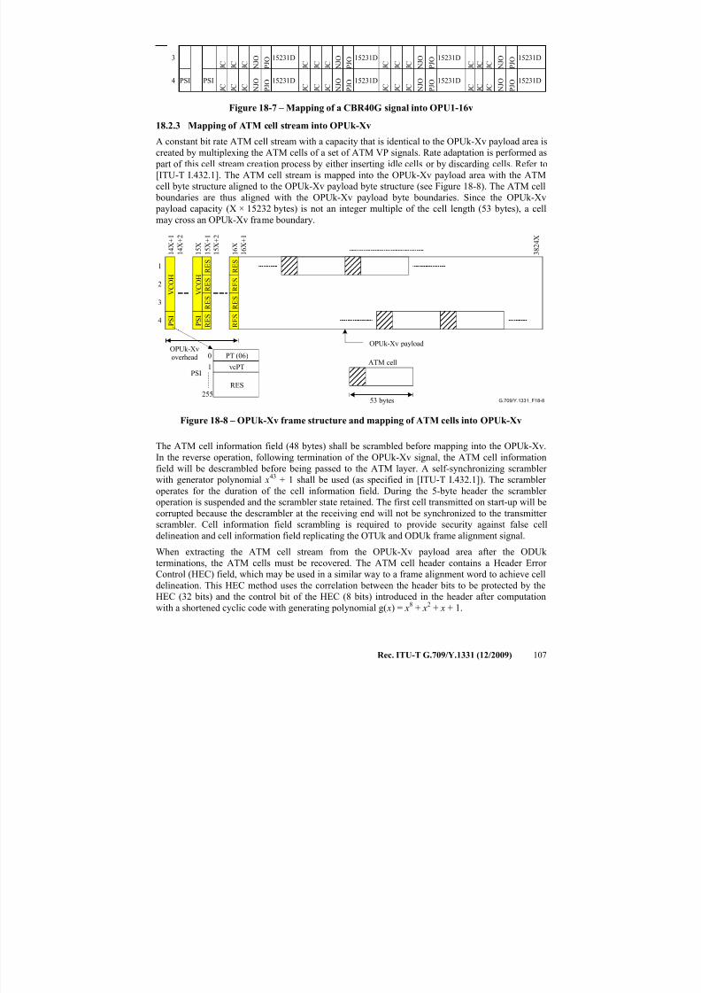
7/16/2019 G-709 ITU_T
http://slidepdf.com/reader/full/g-709-itut 115/218
Rec. ITU-T G.709/Y.1331 (12/2009) 107
3
J C J C J C N J O
P J O
15231D
J C J C J C N J O
P J O
15231D
J C J C J C N J O
P J O
15231D
J C J C J C N J O
P J O
15231D
4 PSI PSI
J C J C J C N J O
P J O
15231D
J C J C J C N J O
P J O
15231D
J C J C J C N J O
P J O
15231D
J C J C J C N J O
P J O
15231D
Figure 18-7 – Mapping of a CBR40G signal into OPU1-16v
18.2.3 Mapping of ATM cell stream into OPUk-Xv
A constant bit rate ATM cell stream with a capacity that is identical to the OPUk-Xv payload area is
created by multiplexing the ATM cells of a set of ATM VP signals. Rate adaptation is performed as
part of this cell stream creation process by either inserting idle cells or by discarding cells. Refer to
[ITU-T I.432.1]. The ATM cell stream is mapped into the OPUk-Xv payload area with the ATM
cell byte structure aligned to the OPUk-Xv payload byte structure (see Figure 18-8). The ATM cell
boundaries are thus aligned with the OPUk-Xv payload byte boundaries. Since the OPUk-Xv
payload capacity (X × 15232 bytes) is not an integer multiple of the cell length (53 bytes), a cell
may cross an OPUk-Xv frame boundary.
G.709/Y.1331_F18-8
3 8 2 4 X
OPUk-Xvoverhead
OPUk-Xv payload
ATM cell
53 bytes255
0
1PSI
1 6 X
1
2
3
4 P S I
1 5 X +
1
1 5 X +
2
R E S
R E S
R E S
P S I
1 5 X
1 4 X +
1
1 4 X +
2
1 6 X +
1
R E S
R E S
R E S
R E S
R E S
V C O H
V C O H
RES
PT (06)
vcPT
Figure 18-8 – OPUk-Xv frame structure and mapping of ATM cells into OPUk-Xv
The ATM cell information field (48 bytes) shall be scrambled before mapping into the OPUk-Xv.
In the reverse operation, following termination of the OPUk-Xv signal, the ATM cell information
field will be descrambled before being passed to the ATM layer. A self-synchronizing scrambler
with generator polynomial x43
+ 1 shall be used (as specified in [ITU-T I.432.1]). The scrambler operates for the duration of the cell information field. During the 5-byte header the scrambler
operation is suspended and the scrambler state retained. The first cell transmitted on start-up will be
corrupted because the descrambler at the receiving end will not be synchronized to the transmitter
scrambler. Cell information field scrambling is required to provide security against false cell
delineation and cell information field replicating the OTUk and ODUk frame alignment signal.
When extracting the ATM cell stream from the OPUk-Xv payload area after the ODUk
terminations, the ATM cells must be recovered. The ATM cell header contains a Header Error
Control (HEC) field, which may be used in a similar way to a frame alignment word to achieve cell
delineation. This HEC method uses the correlation between the header bits to be protected by the
HEC (32 bits) and the control bit of the HEC (8 bits) introduced in the header after computation
with a shortened cyclic code with generating polynomial g( x) = x8 + x2 + x + 1.
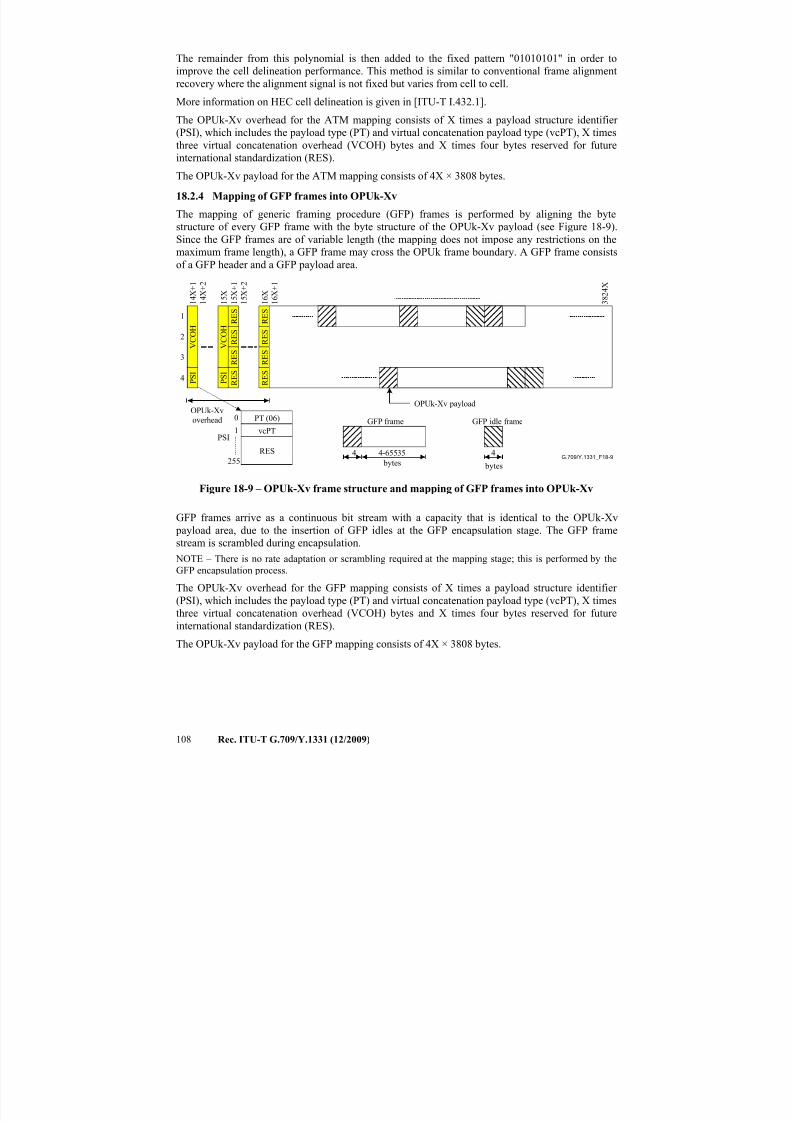
7/16/2019 G-709 ITU_T
http://slidepdf.com/reader/full/g-709-itut 116/218
108 Rec. ITU-T G.709/Y.1331 (12/2009)
The remainder from this polynomial is then added to the fixed pattern "01010101" in order to
improve the cell delineation performance. This method is similar to conventional frame alignment
recovery where the alignment signal is not fixed but varies from cell to cell.
More information on HEC cell delineation is given in [ITU-T I.432.1].
The OPUk-Xv overhead for the ATM mapping consists of X times a payload structure identifier
(PSI), which includes the payload type (PT) and virtual concatenation payload type (vcPT), X timesthree virtual concatenation overhead (VCOH) bytes and X times four bytes reserved for future
international standardization (RES).
The OPUk-Xv payload for the ATM mapping consists of 4X × 3808 bytes.
18.2.4 Mapping of GFP frames into OPUk-Xv
The mapping of generic framing procedure (GFP) frames is performed by aligning the byte
structure of every GFP frame with the byte structure of the OPUk-Xv payload (see Figure 18-9).
Since the GFP frames are of variable length (the mapping does not impose any restrictions on the
maximum frame length), a GFP frame may cross the OPUk frame boundary. A GFP frame consists
of a GFP header and a GFP payload area.
G.709/Y.1331_F18-9
GFP frame
bytes
4 4-65535
GFP idle frame
bytes
4
3 8 2 4 X
OPUk-Xvoverhead
OPUk-Xv payload
255
0
1PSI
1 6 X
1
2
3
4 P S I
1 5 X + 1
1 5 X + 2
R E S
R E S
R E S
P S I
1 5 X
1 4 X + 1
1 4 X + 2
1 6 X + 1
V C O H
R E S
R E S
R E S
V C O H
R E S
R E S
RES
PT (06)
vcPT
Figure 18-9 – OPUk-Xv frame structure and mapping of GFP frames into OPUk-Xv
GFP frames arrive as a continuous bit stream with a capacity that is identical to the OPUk-Xv
payload area, due to the insertion of GFP idles at the GFP encapsulation stage. The GFP frame
stream is scrambled during encapsulation. NOTE – There is no rate adaptation or scrambling required at the mapping stage; this is performed by the
GFP encapsulation process.
The OPUk-Xv overhead for the GFP mapping consists of X times a payload structure identifier
(PSI), which includes the payload type (PT) and virtual concatenation payload type (vcPT), X times
three virtual concatenation overhead (VCOH) bytes and X times four bytes reserved for future
international standardization (RES).
The OPUk-Xv payload for the GFP mapping consists of 4X × 3808 bytes.
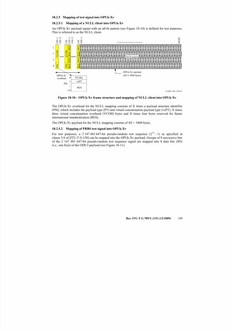
7/16/2019 G-709 ITU_T
http://slidepdf.com/reader/full/g-709-itut 117/218
Rec. ITU-T G.709/Y.1331 (12/2009) 109
18.2.5 Mapping of test signal into OPUk-Xv
18.2.5.1 Mapping of a NULL client into OPUk-Xv
An OPUk-Xv payload signal with an all-0s pattern (see Figure 18-10) is defined for test purposes.
This is referred to as the NULL client.
G.709/Y.1331_F18-10
3 8 2 4
X
OPUk-Xvoverhead
OPUk-Xv payload
(4X × 3808 bytes)
255
0
1PSI
1 6 X
1
2
3
4 P S I
1 5 X + 1
1 5 X + 2
R E S
R E S
R E S
P S I
1 5 X
1 4 X + 1
1 4 X + 2
1 6 X + 1
V C O H
R E S
R E S
R E S
V C O H
R E S
R E S
All-0s pattern
RES
PT (06)
vcPT
Figure 18-10 – OPUk-Xv frame structure and mapping of NULL client into OPUk-Xv
The OPUk-Xv overhead for the NULL mapping consists of X times a payload structure identifier
(PSI), which includes the payload type (PT) and virtual concatenation payload type (vcPT), X times
three virtual concatenation overhead (VCOH) bytes and X times four bytes reserved for future
international standardization (RES).
The OPUk-Xv payload for the NULL mapping consists of 4X × 3808 bytes.
18.2.5.2 Mapping of PRBS test signal into OPUk-Xv
For test purposes, a 2 147 483 647-bit pseudo-random test sequence (231 – 1) as specified in
clause 5.8 of [ITU-T O.150] can be mapped into the OPUk-Xv payload. Groups of 8 successive bits
of the 2 147 483 647-bit pseudo-random test sequence signal are mapped into 8 data bits (8D)
(i.e., one byte) of the ODU3 payload (see Figure 18-11).
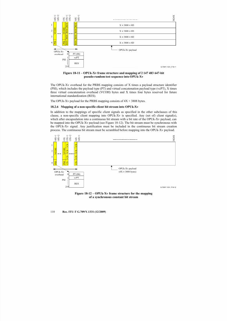
7/16/2019 G-709 ITU_T
http://slidepdf.com/reader/full/g-709-itut 118/218
110 Rec. ITU-T G.709/Y.1331 (12/2009)
G.709/Y.1331_F18-11
3 8 2 4 X
OPUk-Xv
overhead
OPUk-Xv payload
255
0
1PSI
1 6 X
1
2
3
4 P S I R
E S
R E S
R E S
P S I
1 5 X
1 4 X + 1
1 4 X + 2
V C O H
R
E S
R E S
R E S
V C O H
R E S
R E S
X × 3808 × 8D
X × 3808 × 8D
X × 3808 × 8D
X × 3808 × 8D
RES
PT (06)
vcPT
1 5 X + 1
1 5 X + 2
1 6 X + 1
Figure 18-11 – OPUk-Xv frame structure and mapping of 2 147 483 647-bit
pseudo-random test sequence into OPUk-Xv
The OPUk-Xv overhead for the PRBS mapping consists of X times a payload structure identifier
(PSI), which includes the payload type (PT) and virtual concatenation payload type (vcPT), X times
three virtual concatenation overhead (VCOH) bytes and X times four bytes reserved for future
international standardization (RES).
The OPUk-Xv payload for the PRBS mapping consists of 4X × 3808 bytes.
18.2.6 Mapping of a non-specific client bit stream into OPUk-Xv
In addition to the mappings of specific client signals as specified in the other subclauses of this
clause, a non-specific client mapping into OPUk-Xv is specified. Any (set of) client signal(s),which after encapsulation into a continuous bit stream with a bit rate of the OPUk-Xv payload, can
be mapped into the OPUk-Xv payload (see Figure 18-12). The bit stream must be synchronous with
the OPUk-Xv signal. Any justification must be included in the continuous bit stream creation
process. The continuous bit stream must be scrambled before mapping into the OPUk-Xv payload.
G.709/Y.1331_F18-12
3 8 2 4 X
OPUk-Xv
overhead
OPUk-Xv payload
(4X × 3808 bytes)
255
0
1PSI
1 6 X
1
2
3
4 P S I
1 5 X + 1
1 5 X + 2
C S
C S
C S
P S I
1 5 X
1 4 X + 1
1 4 X + 2
1 6 X + 1
V C O H
C S
C S
C S
V C O H
C S
C S
RES
PT (06)
vcPT
Figure 18-12 – OPUk-Xv frame structure for the mappingof a synchronous constant bit stream
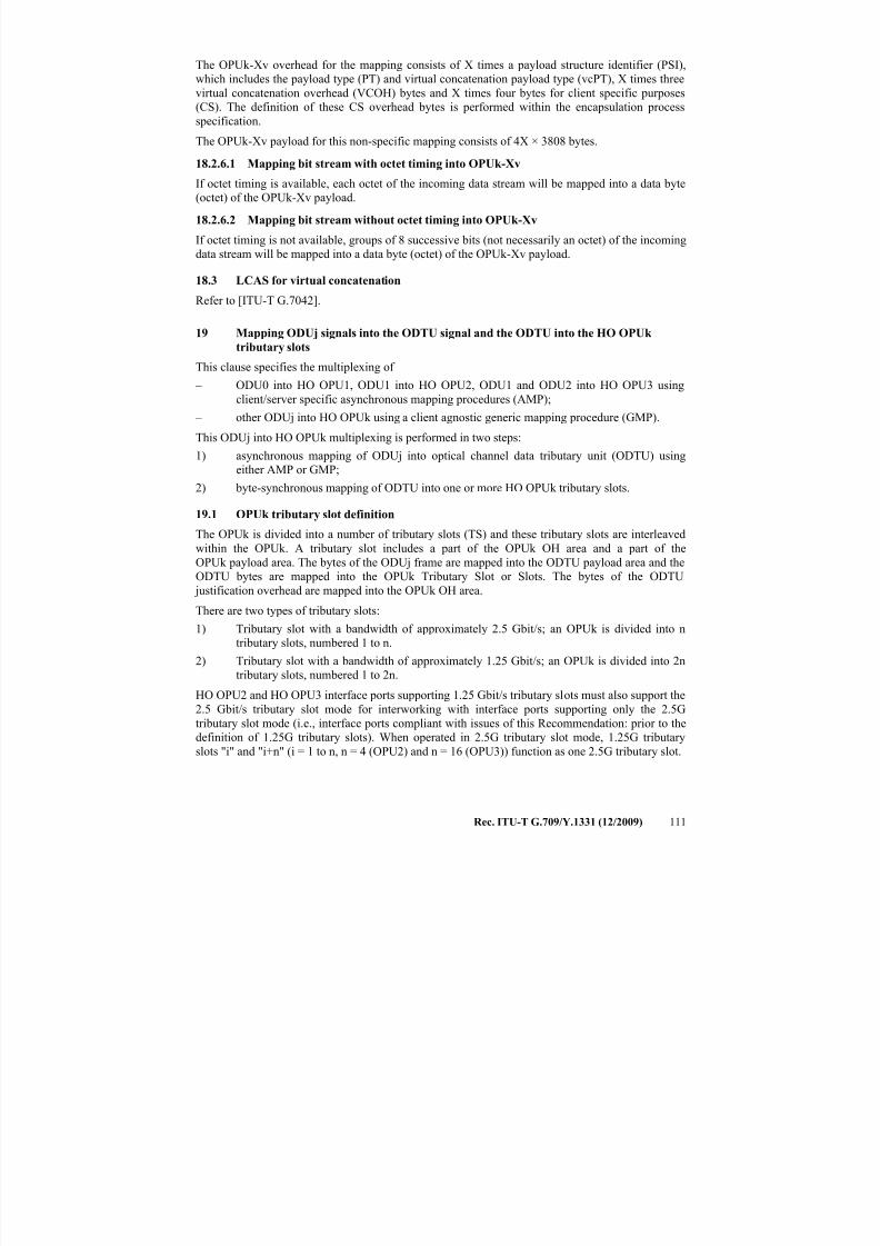
7/16/2019 G-709 ITU_T
http://slidepdf.com/reader/full/g-709-itut 119/218
Rec. ITU-T G.709/Y.1331 (12/2009) 111
The OPUk-Xv overhead for the mapping consists of X times a payload structure identifier (PSI),
which includes the payload type (PT) and virtual concatenation payload type (vcPT), X times three
virtual concatenation overhead (VCOH) bytes and X times four bytes for client specific purposes
(CS). The definition of these CS overhead bytes is performed within the encapsulation process
specification.
The OPUk-Xv payload for this non-specific mapping consists of 4X × 3808 bytes.
18.2.6.1 Mapping bit stream with octet timing into OPUk-Xv
If octet timing is available, each octet of the incoming data stream will be mapped into a data byte
(octet) of the OPUk-Xv payload.
18.2.6.2 Mapping bit stream without octet timing into OPUk-Xv
If octet timing is not available, groups of 8 successive bits (not necessarily an octet) of the incoming
data stream will be mapped into a data byte (octet) of the OPUk-Xv payload.
18.3 LCAS for virtual concatenation
Refer to [ITU-T G.7042].
19 Mapping ODUj signals into the ODTU signal and the ODTU into the HO OPUk
tributary slots
This clause specifies the multiplexing of
– ODU0 into HO OPU1, ODU1 into HO OPU2, ODU1 and ODU2 into HO OPU3 using
client/server specific asynchronous mapping procedures (AMP);
– other ODUj into HO OPUk using a client agnostic generic mapping procedure (GMP).
This ODUj into HO OPUk multiplexing is performed in two steps:
1) asynchronous mapping of ODUj into optical channel data tributary unit (ODTU) usingeither AMP or GMP;
2) byte-synchronous mapping of ODTU into one or more HO OPUk tributary slots.
19.1 OPUk tributary slot definition
The OPUk is divided into a number of tributary slots (TS) and these tributary slots are interleaved
within the OPUk. A tributary slot includes a part of the OPUk OH area and a part of the
OPUk payload area. The bytes of the ODUj frame are mapped into the ODTU payload area and the
ODTU bytes are mapped into the OPUk Tributary Slot or Slots. The bytes of the ODTU
justification overhead are mapped into the OPUk OH area.
There are two types of tributary slots:
1) Tributary slot with a bandwidth of approximately 2.5 Gbit/s; an OPUk is divided into n
tributary slots, numbered 1 to n.
2) Tributary slot with a bandwidth of approximately 1.25 Gbit/s; an OPUk is divided into 2n
tributary slots, numbered 1 to 2n.
HO OPU2 and HO OPU3 interface ports supporting 1.25 Gbit/s tributary slots must also support the
2.5 Gbit/s tributary slot mode for interworking with interface ports supporting only the 2.5G
tributary slot mode (i.e., interface ports compliant with issues of this Recommendation: prior to the
definition of 1.25G tributary slots). When operated in 2.5G tributary slot mode, 1.25G tributary
slots "i" and "i+n" (i = 1 to n, n = 4 (OPU2) and n = 16 (OPU3)) function as one 2.5G tributary slot.
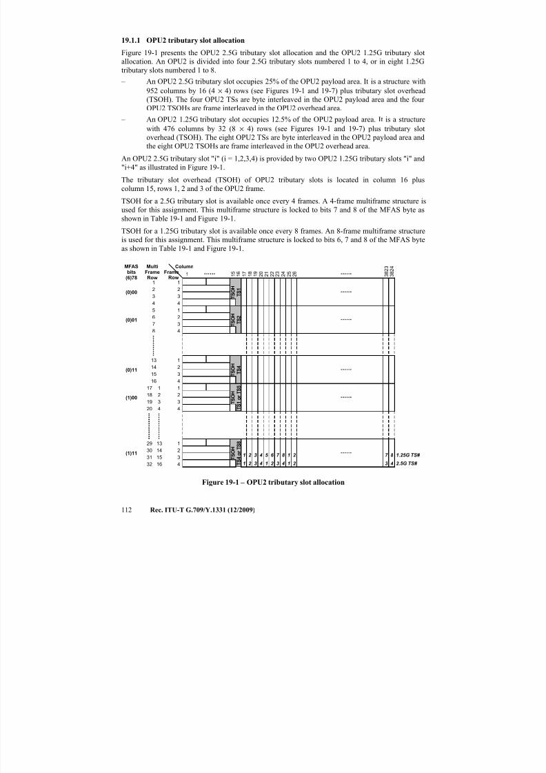
7/16/2019 G-709 ITU_T
http://slidepdf.com/reader/full/g-709-itut 120/218
112 Rec. ITU-T G.709/Y.1331 (12/2009)
19.1.1 OPU2 tributary slot allocation
Figure 19-1 presents the OPU2 2.5G tributary slot allocation and the OPU2 1.25G tributary slot
allocation. An OPU2 is divided into four 2.5G tributary slots numbered 1 to 4, or in eight 1.25G
tributary slots numbered 1 to 8.
– An OPU2 2.5G tributary slot occupies 25% of the OPU2 payload area. It is a structure with
952 columns by 16 (4 × 4) rows (see Figures 19-1 and 19-7) plus tributary slot overhead(TSOH). The four OPU2 TSs are byte interleaved in the OPU2 payload area and the four
OPU2 TSOHs are frame interleaved in the OPU2 overhead area.
– An OPU2 1.25G tributary slot occupies 12.5% of the OPU2 payload area. It is a structure
with 476 columns by 32 (8 × 4) rows (see Figures 19-1 and 19-7) plus tributary slot
overhead (TSOH). The eight OPU2 TSs are byte interleaved in the OPU2 payload area and
the eight OPU2 TSOHs are frame interleaved in the OPU2 overhead area.
An OPU2 2.5G tributary slot "i" (i = 1,2,3,4) is provided by two OPU2 1.25G tributary slots "i" and
"i+4" as illustrated in Figure 19-1.
The tributary slot overhead (TSOH) of OPU2 tributary slots is located in column 16 plus
column 15, rows 1, 2 and 3 of the OPU2 frame.
TSOH for a 2.5G tributary slot is available once every 4 frames. A 4-frame multiframe structure is
used for this assignment. This multiframe structure is locked to bits 7 and 8 of the MFAS byte as
shown in Table 19-1 and Figure 19-1.
TSOH for a 1.25G tributary slot is available once every 8 frames. An 8-frame multiframe structure
is used for this assignment. This multiframe structure is locked to bits 6, 7 and 8 of the MFAS byte
as shown in Table 19-1 and Figure 19-1.
1 1 6
1 7
3 8 2 4
FrameRow
Column
1 8
1 9
2 0
3 8 2 3
2 1
1 5
1.25G TS#
2.5G TS#
1 2 3 4 5 6 7 8
1 2 3 4 1 2 3 4
1 2
1 2
7 8
3 4
1
2
3
4
MFASbits
(6)78
1
2
3
4
(0)00
(0)01
MultiFrameRow
1
2
3
4
5
6
7
8
1
2
34
1
2
3
4
(0)11
(1)00
13
14
1516
17
18
19
20
1
2
3
4
(1)11
29
30
31
32
1
2
3
4
13
14
15
16
T S O H
T S 2
T
S O H
T S 4
T S O H
T S 1 o r T S 5
T S O H
T S 4 o r T S 8
2 3
2 4
2 5
2 6
2 2
T S O H
T S 1
Figure 19-1 – OPU2 tributary slot allocation
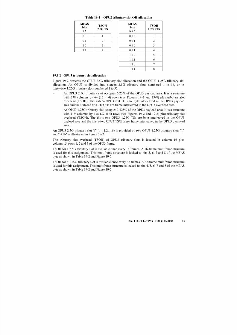
7/16/2019 G-709 ITU_T
http://slidepdf.com/reader/full/g-709-itut 121/218
Rec. ITU-T G.709/Y.1331 (12/2009) 113
Table 19-1 – OPU2 tributary slot OH allocation
MFAS
bits
7 8
TSOH
2.5G TS
MFAS
bits
6 7 8
TSOH
1.25G TS
0 0 1 0 0 0 1
0 1 2 0 0 1 2
1 0 3 0 1 0 3
1 1 4 0 1 1 4
1 0 0 5
1 0 1 6
1 1 0 7
1 1 1 8
19.1.2 OPU3 tributary slot allocation
Figure 19-2 presents the OPU3 2.5G tributary slot allocation and the OPU3 1.25G tributary slotallocation. An OPU3 is divided into sixteen 2.5G tributary slots numbered 1 to 16, or in
thirty-two 1.25G tributary slots numbered 1 to 32.
– An OPU3 2.5G tributary slot occupies 6.25% of the OPU3 payload area. It is a structure
with 238 columns by 64 (16 × 4) rows (see Figures 19-2 and 19-8) plus tributary slot
overhead (TSOH). The sixteen OPU3 2.5G TSs are byte interleaved in the OPU3 payload
area and the sixteen OPU3 TSOHs are frame interleaved in the OPU3 overhead area.
– An OPU3 1.25G tributary slot occupies 3.125% of the OPU3 payload area. It is a structure
with 119 columns by 128 (32 × 4) rows (see Figures 19-2 and 19-8) plus tributary slot
overhead (TSOH). The thirty-two OPU3 1.25G TSs are byte interleaved in the OPU3
payload area and the thirty-two OPU3 TSOHs are frame interleaved in the OPU3 overheadarea.
An OPU3 2.5G tributary slot "i" (i = 1,2,..16) is provided by two OPU3 1.25G tributary slots "i"
and "i+16" as illustrated in Figure 19-2.
The tributary slot overhead (TSOH) of OPU3 tributary slots is located in column 16 plus
column 15, rows 1, 2 and 3 of the OPU3 frame.
TSOH for a 2.5G tributary slot is available once every 16 frames. A 16-frame multiframe structure
is used for this assignment. This multiframe structure is locked to bits 5, 6, 7 and 8 of the MFAS
byte as shown in Table 19-2 and Figure 19-2.
TSOH for a 1.25G tributary slot is available once every 32 frames. A 32-frame multiframe structureis used for this assignment. This multiframe structure is locked to bits 4, 5, 6, 7 and 8 of the MFAS
byte as shown in Table 19-2 and Figure 19-2.
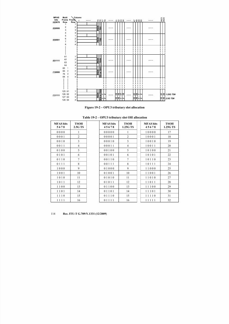
7/16/2019 G-709 ITU_T
http://slidepdf.com/reader/full/g-709-itut 122/218
114 Rec. ITU-T G.709/Y.1331 (12/2009)
1 1 6
1 7
3 8 2 4
FrameRow
Column
1 8
3 1
3 8 2 3
3 2
1 5
1.25G TS#
2.5G TS#
T S O H
T S 1
1 2 1 5
1 6
1 7
1 8
1 2 1 5
1 6 1 2
3 1
3 2
1 5
1 6
1
2
3
4
1
23
4
1
2
3
4
1
2
3
4
1
2
3
4
T S O
H
T S 2
T S O H
T S 1 6
T S O H
T S 1 o r T S 1 7
T S O H
T S 1 6 o r T S 3 2
3 4
3 3
MFASbits
(4)5678
(0)0000
(0)0001
MultiFrameRow
1
2
3
4
5
67
8
(0)1111
(1)0000
61
62
63
64
65
66
76
68
(1)1111
125
126
127
128
1
2
3
4
61
62
63
64
4 7
4 8
3 1
3 2 1 2
1 5
1 6 1 2
5 0
4 9
Figure 19-2 – OPU3 tributary slot allocation
Table 19-2 – OPU3 tributary slot OH allocation
MFAS bits
5 6 7 8
TSOH
2.5G TS
MFAS bits
4 5 6 7 8
TSOH
1.25G TS
MFAS bits
4 5 6 7 8
TSOH
1.25G TS
0 0 0 0 1 0 0 0 0 0 1 1 0 0 0 0 17
0 0 0 1 2 0 0 0 0 1 2 1 0 0 0 1 18
0 0 1 0 3 0 0 0 1 0 3 1 0 0 1 0 19
0 0 1 1 4 0 0 0 1 1 4 1 0 0 1 1 20
0 1 0 0 5 0 0 1 0 0 5 1 0 1 0 0 21
0 1 0 1 6 0 0 1 0 1 6 1 0 1 0 1 22
0 1 1 0 7 0 0 1 1 0 7 1 0 1 1 0 23
0 1 1 1 8 0 0 1 1 1 8 1 0 1 1 1 24
1 0 0 0 9 0 1 0 0 0 9 1 1 0 0 0 25
1 0 0 1 10 0 1 0 0 1 10 1 1 0 0 1 26
1 0 1 0 11 0 1 0 1 0 11 1 1 0 1 0 27
1 0 1 1 12 0 1 0 1 1 12 1 1 0 1 1 28
1 1 0 0 13 0 1 1 0 0 13 1 1 1 0 0 29
1 1 0 1 14 0 1 1 0 1 14 1 1 1 0 1 30
1 1 1 0 15 0 1 1 1 0 15 1 1 1 1 0 311 1 1 1 16 0 1 1 1 1 16 1 1 1 1 1 32
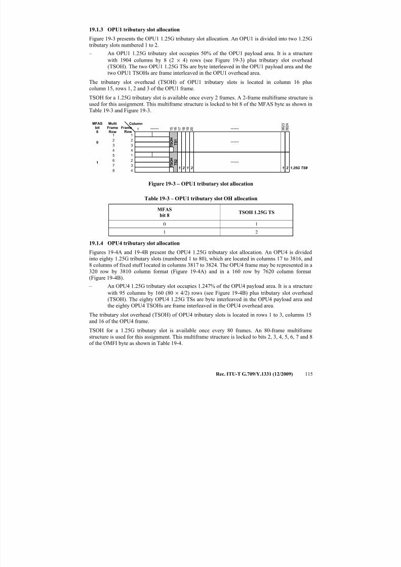
7/16/2019 G-709 ITU_T
http://slidepdf.com/reader/full/g-709-itut 123/218
Rec. ITU-T G.709/Y.1331 (12/2009) 115
19.1.3 OPU1 tributary slot allocation
Figure 19-3 presents the OPU1 1.25G tributary slot allocation. An OPU1 is divided into two 1.25G
tributary slots numbered 1 to 2.
– An OPU1 1.25G tributary slot occupies 50% of the OPU1 payload area. It is a structure
with 1904 columns by 8 (2 × 4) rows (see Figure 19-3) plus tributary slot overhead
(TSOH). The two OPU1 1.25G TSs are byte interleaved in the OPU1 payload area and thetwo OPU1 TSOHs are frame interleaved in the OPU1 overhead area.
The tributary slot overhead (TSOH) of OPU1 tributary slots is located in column 16 plus
column 15, rows 1, 2 and 3 of the OPU1 frame.
TSOH for a 1.25G tributary slot is available once every 2 frames. A 2-frame multiframe structure is
used for this assignment. This multiframe structure is locked to bit 8 of the MFAS byte as shown in
Table 19-3 and Figure 19-3.
1 1 6
1 7
3 8 2 4
FrameRow
Column
1 8
1 9
2 0
3 8 2 3
1 5
1.25G TS#
T S O H
T S 1
1 2 1 2 1 2
1
2
3
4
MFASbit8
1
2
3
4
0
1
MultiFrameRow
1
2
3
4
5
6
7
8
T S O H
T S 2
Figure 19-3 – OPU1 tributary slot allocation
Table 19-3 – OPU1 tributary slot OH allocation
MFAS
bit 8TSOH 1.25G TS
0 1
1 2
19.1.4 OPU4 tributary slot allocation
Figures 19-4A and 19-4B present the OPU4 1.25G tributary slot allocation. An OPU4 is divided
into eighty 1.25G tributary slots (numbered 1 to 80), which are located in columns 17 to 3816, and
8 columns of fixed stuff located in columns 3817 to 3824. The OPU4 frame may be represented in a
320 row by 3810 column format (Figure 19-4A) and in a 160 row by 7620 column format
(Figure 19-4B).
– An OPU4 1.25G tributary slot occupies 1.247% of the OPU4 payload area. It is a structure
with 95 columns by 160 (80 × 4/2) rows (see Figure 19-4B) plus tributary slot overhead
(TSOH). The eighty OPU4 1.25G TSs are byte interleaved in the OPU4 payload area and
the eighty OPU4 TSOHs are frame interleaved in the OPU4 overhead area.
The tributary slot overhead (TSOH) of OPU4 tributary slots is located in rows 1 to 3, columns 15
and 16 of the OPU4 frame.
TSOH for a 1.25G tributary slot is available once every 80 frames. An 80-frame multiframe
structure is used for this assignment. This multiframe structure is locked to bits 2, 3, 4, 5, 6, 7 and 8
of the OMFI byte as shown in Table 19-4.
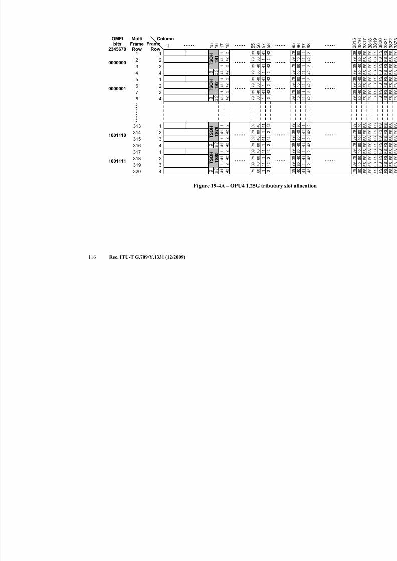
7/16/2019 G-709 ITU_T
http://slidepdf.com/reader/full/g-709-itut 124/218
116 Rec. ITU-T G.709/Y.1331 (12/2009)
1 1 6
1 7Frame
Row
Column
1 8
5 5
5 6
1 5
1
2
34
1
2
3
4
1
2
3
4
1
2
3
4
5 8
5 7
OMFIbits
2345678
0000000
0000001
MultiFrameRow
1
2
34
5
6
7
8
1001110
1001111
313
314
315
316
317
318
319
320
9 5
9 6
9 8
9 7
1
4 1
1
4 1
2
4 2
2
4 2
3 9
7 9
3 9
7 9
4 0
8 0
4 0
8 0
4 1
1
4 1
1
4 2
2
4 2
2
7 9
3 9
7 9
3 9
8 0
4 0
8 0
4 0
1
4 1
1
4 1
2
4 2
2
4 2
1
4 1
1
4 1
2
4 2
2
4 2
3 9
7 9
3 9
7 9
4 0
8 0
4 0
8 0
4 1
1
4 1
1
4 2
2
4 2
2
7 9
3 9
7 9
3 9
8 0
4 0
8 0
4 0
1
4 1
1
4 1
2
4 2
2
4 2
1
4 1
1
4 1
2
4 2
2
4 2
3 9
7 9
3 9
7 9
4 0
8 0
4 0
8 0
4 1
1
4 1
1
4 2
2
4 2
2
7 9
3 9
7 9
3 9
8 0
4 0
8 0
4 0
1
4 1
1
4 1
2
4 2
2
4 2
1
4 1
1
4 1
2
4 2
2
4 2
3 9
7 9
3 9
7 9
4 0
8 0
4 0
8 0
4 1
1
4 1
1
4 2
2
4 2
2
7 9
3 9
7 9
3 9
8 0
4 0
8 0
4 0
1
4 1
1
4 1
2
4 2
2
4 2
T S O H
T S 1
OMFI
PSI
T S O H
T S 2
OMFI
PSI
T S O H
T
S 7 9
OMFI
PSI
T S O H
T S 8 0
OMFI
PSI
Figure 19-4A – OPU4 1.25G tributary slot allocation
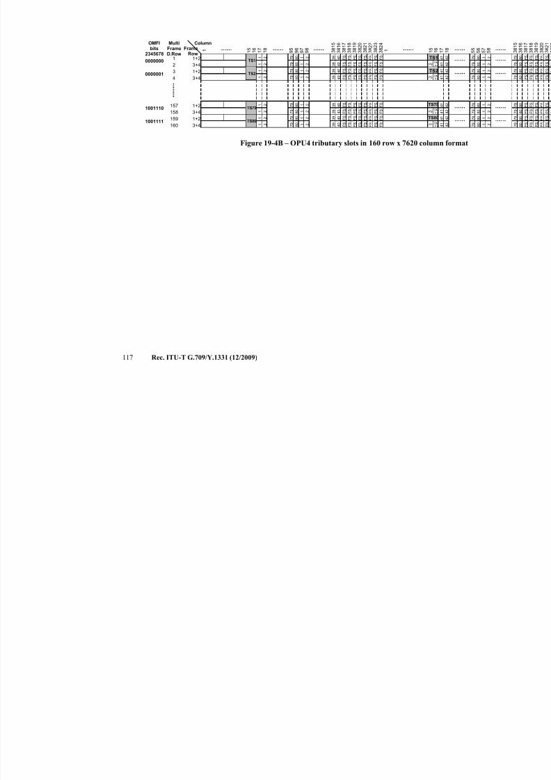
7/16/2019 G-709 ITU_T
http://slidepdf.com/reader/full/g-709-itut 125/218
117 Rec. ITU-T G.709/Y.1331 (12/2009)
1 1 6
1 7
3 8 2 4
FrameRow
Column
1 8
3 8 2 3
1 5
1+2
3+4
OMFIbits
2345678
0000000
MultiFrameD.Row
1
2
3
4
157
158
159
160
9 5
9 6
9 8
9 7
1 4 1
1 4 1
2 4 2
2 4 2
7 9
7 9
8 0
8 0
1
1
2
2 3 9
3 9
4 0
4 0
F S
F S
F S
F S
F S
F S
F S
F S
F S
F S
F S
F S
F S
F S
F S
F S
3 8 2 2
3 8 2 1
3 8 2 0
3 8 1 9
3 8 1 8
3 8 1 7
3 8 1 6
3 8 1 5
1 1 6
1 7
1 8
1 5
1+2
3+4
1 4 1
1 4 1
2 4 2
2 4 2
7 9
7 9
8 0
8 0
1
1
2
2 3 9
3 9
4 0
4 0
F S
F S
F S
F S
F S
F S
F S
F S
F S
F S
F S
F S
F S
F S
F S
F S
1+2
3+4
1 4 1
1 4 1
2 4 2
2 4 2
7 9
7 9
8 0
8 0
1
1
2
2 3 9
3 9
4 0
4 0
F S
F S
F S
F S
F S
F S
F S
F S
F S
F S
F S
F S
F S
F S
F S
F S
1+2
3+4
1 4 1
1 4 1
2 4 2
2 4 2
7 9
7 9
8 0
8 0
1
1
2
2 3 9
3 9
4 0
4 0
F S
F S
F S
F S
F S
F S
F S
F S
F S
F S
F S
F S
F S
F S
F S
F S
0000001
1001110
1001111
TS1OMFI
PSI
TS1
TS2OMFI
PSI
TS2
OMFI
PSI
TS79
OMFI
PSI
TS80
TS79
TS80
Figure 19-4B – OPU4 tributary slots in 160 row x 7620 column forma
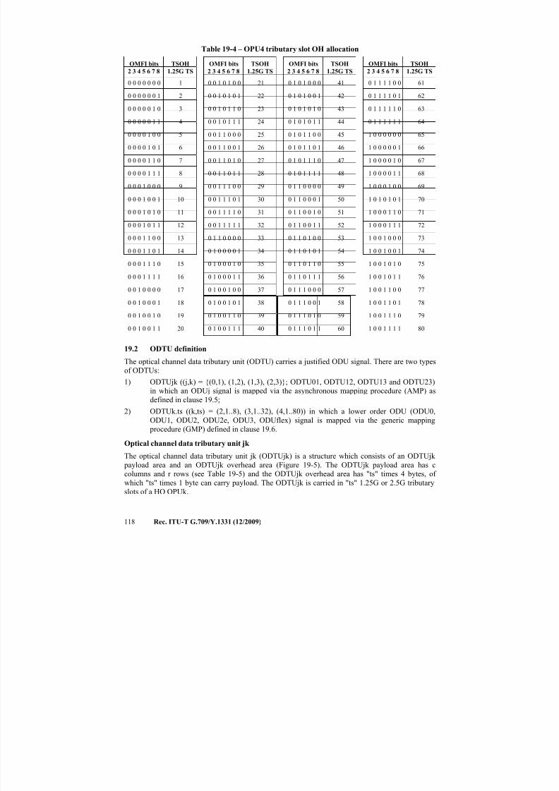
7/16/2019 G-709 ITU_T
http://slidepdf.com/reader/full/g-709-itut 126/218
118 Rec. ITU-T G.709/Y.1331 (12/2009)
Table 19-4 – OPU4 tributary slot OH allocation
OMFI bits
2 3 4 5 6 7 8
TSOH
1.25G TS
OMFI bits
2 3 4 5 6 7 8
TSOH
1.25G TS
OMFI bits
2 3 4 5 6 7 8
TSOH
1.25G TS
OMFI bits
2 3 4 5 6 7 8
TSOH
1.25G TS
0 0 0 0 0 0 0 1 0 0 1 0 1 0 0 21 0 1 0 1 0 0 0 41 0 1 1 1 1 0 0 61
0 0 0 0 0 0 1 2 0 0 1 0 1 0 1 22 0 1 0 1 0 0 1 42 0 1 1 1 1 0 1 62
0 0 0 0 0 1 0 3 0 0 1 0 1 1 0 23 0 1 0 1 0 1 0 43 0 1 1 1 1 1 0 63
0 0 0 0 0 1 1 4 0 0 1 0 1 1 1 24 0 1 0 1 0 1 1 44 0 1 1 1 1 1 1 64
0 0 0 0 1 0 0 5 0 0 1 1 0 0 0 25 0 1 0 1 1 0 0 45 1 0 0 0 0 0 0 65
0 0 0 0 1 0 1 6 0 0 1 1 0 0 1 26 0 1 0 1 1 0 1 46 1 0 0 0 0 0 1 66
0 0 0 0 1 1 0 7 0 0 1 1 0 1 0 27 0 1 0 1 1 1 0 47 1 0 0 0 0 1 0 67
0 0 0 0 1 1 1 8 0 0 1 1 0 1 1 28 0 1 0 1 1 1 1 48 1 0 0 0 0 1 1 68
0 0 0 1 0 0 0 9 0 0 1 1 1 0 0 29 0 1 1 0 0 0 0 49 1 0 0 0 1 0 0 69
0 0 0 1 0 0 1 10 0 0 1 1 1 0 1 30 0 1 1 0 0 0 1 50 1 0 1 0 1 0 1 70
0 0 0 1 0 1 0 11 0 0 1 1 1 1 0 31 0 1 1 0 0 1 0 51 1 0 0 0 1 1 0 71
0 0 0 1 0 1 1 12 0 0 1 1 1 1 1 32 0 1 1 0 0 1 1 52 1 0 0 0 1 1 1 72
0 0 0 1 1 0 0 13 0 1 1 0 0 0 0 33 0 1 1 0 1 0 0 53 1 0 0 1 0 0 0 73
0 0 0 1 1 0 1 14 0 1 0 0 0 0 1 34 0 1 1 0 1 0 1 54 1 0 0 1 0 0 1 74
0 0 0 1 1 1 0 15 0 1 0 0 0 1 0 35 0 1 1 0 1 1 0 55 1 0 0 1 0 1 0 75
0 0 0 1 1 1 1 16 0 1 0 0 0 1 1 36 0 1 1 0 1 1 1 56 1 0 0 1 0 1 1 76
0 0 1 0 0 0 0 17 0 1 0 0 1 0 0 37 0 1 1 1 0 0 0 57 1 0 0 1 1 0 0 77
0 0 1 0 0 0 1 18 0 1 0 0 1 0 1 38 0 1 1 1 0 0 1 58 1 0 0 1 1 0 1 78
0 0 1 0 0 1 0 19 0 1 0 0 1 1 0 39 0 1 1 1 0 1 0 59 1 0 0 1 1 1 0 79
0 0 1 0 0 1 1 20 0 1 0 0 1 1 1 40 0 1 1 1 0 1 1 60 1 0 0 1 1 1 1 80
19.2 ODTU definition
The optical channel data tributary unit (ODTU) carries a justified ODU signal. There are two types
of ODTUs:
1) ODTUjk ((j,k) = {(0,1), (1,2), (1,3), (2,3)}; ODTU01, ODTU12, ODTU13 and ODTU23)in which an ODUj signal is mapped via the asynchronous mapping procedure (AMP) as
defined in clause 19.5;
2) ODTUk.ts ((k,ts) = (2,1..8), (3,1..32), (4,1..80)) in which a lower order ODU (ODU0,
ODU1, ODU2, ODU2e, ODU3, ODUflex) signal is mapped via the generic mapping
procedure (GMP) defined in clause 19.6.
Optical channel data tributary unit jk
The optical channel data tributary unit jk (ODTUjk) is a structure which consists of an ODTUjk
payload area and an ODTUjk overhead area (Figure 19-5). The ODTUjk payload area has c
columns and r rows (see Table 19-5) and the ODTUjk overhead area has "ts" times 4 bytes, of
which "ts" times 1 byte can carry payload. The ODTUjk is carried in "ts" 1.25G or 2.5G tributaryslots of a HO OPUk.
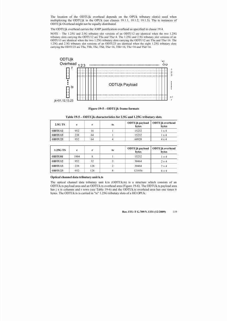
7/16/2019 G-709 ITU_T
http://slidepdf.com/reader/full/g-709-itut 127/218
Rec. ITU-T G.709/Y.1331 (12/2009) 119
The location of the ODTUjk overhead depends on the OPUk tributary slot(s) used when
multiplexing the ODTUjk in the OPUk (see clauses 19.1.1, 19.1.2, 19.1.3). The ts instances of
ODTUjk Overhead might not be equally distributed.
The ODTUjk overhead carries the AMP justification overhead as specified in clause 19.4.
NOTE – The 1.25G and 2.5G tributary slot versions of an ODTU12 are identical when the two 1.25G
tributary slots carrying the ODTU12 are TSa and TSa+4. The 1.25G and 2.5G tributary slot versions of an
ODTU13 are identical when the two 1.25G tributary slots carrying the ODTU12 are TSa and TSa+16. The
1.25G and 2.5G tributary slot versions of an ODTU23 are identical when the eight 1.25G tributary slots
carrying the ODTU23 are TSa, TSb, TSc, TSd, TSa+16, TSb+16, TSc+16 and TSd+16.
123
r-1r
1 23 c - 1
c1
tsODTUjk Payload
ODTUjk
Overhead
jk=01,12,13,23
Figure 19-5 – ODTUjk frame formats
Table 19-5 – ODTUjk characteristics for 2.5G and 1.25G tributary slots
2.5G TS c r tsODTUjk payload
bytes
ODTUjk overhead
bytes
ODTU12 952 16 1 15232 1 x 4
ODTU13 238 64 1 15232 1 x 4
ODTU23 952 64 4 60928 4 x 4
1.25G TS c r tsODTUjk payload
bytes
ODTUjk overhead
bytes
ODTU01 1904 8 1 15232 1 × 4
ODTU12 952 32 2 30464 2 × 4
ODTU13 238 128 2 30464 2 × 4
ODTU23 952 128 8 121856 8 × 4
Optical channel data tributary unit k.ts
The optical channel data tributary unit k.ts (ODTUk.ts) is a structure which consists of an
ODTUk.ts payload area and an ODTUk.ts overhead area (Figure 19-6). The ODTUk.ts payload area
has j x ts columns and r rows (see Table 19-6) and the ODTUk.ts overhead area has one times 6
bytes. The ODTUk.ts is carried in "ts" 1.25G tributary slots of a HO OPUk.
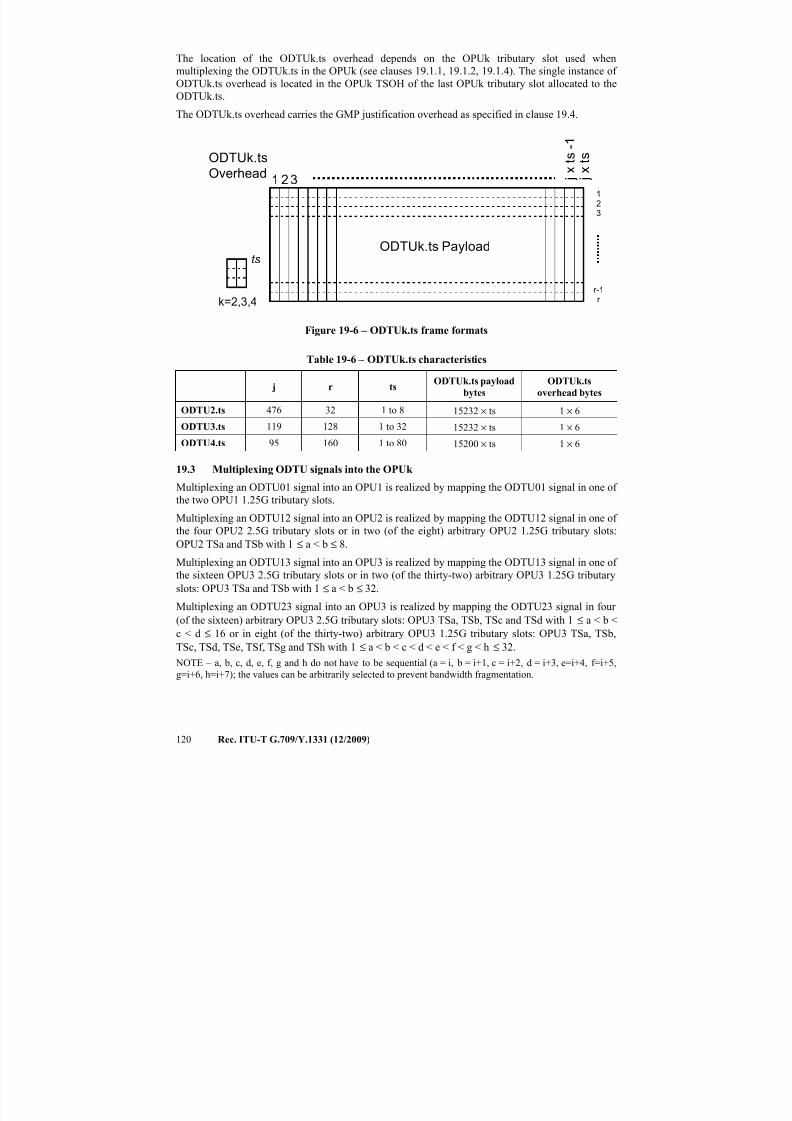
7/16/2019 G-709 ITU_T
http://slidepdf.com/reader/full/g-709-itut 128/218
120 Rec. ITU-T G.709/Y.1331 (12/2009)
The location of the ODTUk.ts overhead depends on the OPUk tributary slot used when
multiplexing the ODTUk.ts in the OPUk (see clauses 19.1.1, 19.1.2, 19.1.4). The single instance of
ODTUk.ts overhead is located in the OPUk TSOH of the last OPUk tributary slot allocated to the
ODTUk.ts.
The ODTUk.ts overhead carries the GMP justification overhead as specified in clause 19.4.
123
r-1r
1 23 j x
t s - 1
j x
t s
ts
ODTUk.ts Payload
ODTUk.ts
Overhead
k=2,3,4
Figure 19-6 – ODTUk.ts frame formats
Table 19-6 – ODTUk.ts characteristics
j r tsODTUk.ts payload
bytes
ODTUk.ts
overhead bytes
ODTU2.ts 476 32 1 to 8 15232 × ts 1 × 6
ODTU3.ts 119 128 1 to 32 15232 × ts 1 × 6
ODTU4.ts 95 160 1 to 80 15200 × ts 1 × 6
19.3 Multiplexing ODTU signals into the OPUk
Multiplexing an ODTU01 signal into an OPU1 is realized by mapping the ODTU01 signal in one of
the two OPU1 1.25G tributary slots.
Multiplexing an ODTU12 signal into an OPU2 is realized by mapping the ODTU12 signal in one of
the four OPU2 2.5G tributary slots or in two (of the eight) arbitrary OPU2 1.25G tributary slots:
OPU2 TSa and TSb with 1 ≤ a < b ≤ 8.
Multiplexing an ODTU13 signal into an OPU3 is realized by mapping the ODTU13 signal in one of
the sixteen OPU3 2.5G tributary slots or in two (of the thirty-two) arbitrary OPU3 1.25G tributary
slots: OPU3 TSa and TSb with 1 ≤ a < b ≤ 32.
Multiplexing an ODTU23 signal into an OPU3 is realized by mapping the ODTU23 signal in four
(of the sixteen) arbitrary OPU3 2.5G tributary slots: OPU3 TSa, TSb, TSc and TSd with 1 ≤ a < b <
c < d ≤ 16 or in eight (of the thirty-two) arbitrary OPU3 1.25G tributary slots: OPU3 TSa, TSb,
TSc, TSd, TSe, TSf, TSg and TSh with 1 ≤ a < b < c < d < e < f < g < h ≤ 32.
NOTE – a, b, c, d, e, f, g and h do not have to be sequential (a = i, b = i+1, c = i+2, d = i+3, e=i+4, f=i+5,
g=i+6, h=i+7); the values can be arbitrarily selected to prevent bandwidth fragmentation.
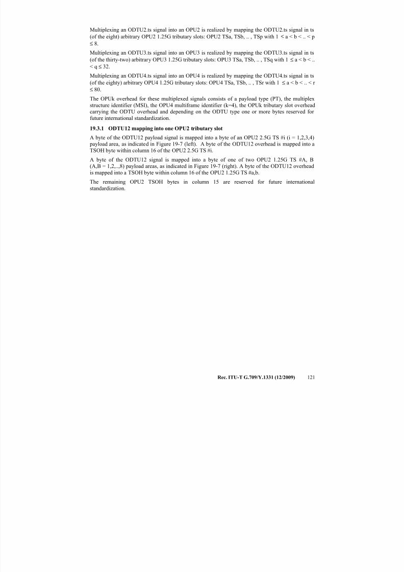
7/16/2019 G-709 ITU_T
http://slidepdf.com/reader/full/g-709-itut 129/218
Rec. ITU-T G.709/Y.1331 (12/2009) 121
Multiplexing an ODTU2.ts signal into an OPU2 is realized by mapping the ODTU2.ts signal in ts
(of the eight) arbitrary OPU2 1.25G tributary slots: OPU2 TSa, TSb, .. , TSp with 1 ≤ a < b < .. < p
≤ 8.
Multiplexing an ODTU3.ts signal into an OPU3 is realized by mapping the ODTU3.ts signal in ts
(of the thirty-two) arbitrary OPU3 1.25G tributary slots: OPU3 TSa, TSb, .. , TSq with 1 ≤ a < b < ..
< q ≤ 32.Multiplexing an ODTU4.ts signal into an OPU4 is realized by mapping the ODTU4.ts signal in ts
(of the eighty) arbitrary OPU4 1.25G tributary slots: OPU4 TSa, TSb, .. , TSr with 1 ≤ a < b < .. < r
≤ 80.
The OPUk overhead for these multiplexed signals consists of a payload type (PT), the multiplex
structure identifier (MSI), the OPU4 multiframe identifier (k=4), the OPUk tributary slot overhead
carrying the ODTU overhead and depending on the ODTU type one or more bytes reserved for
future international standardization.
19.3.1 ODTU12 mapping into one OPU2 tributary slot
A byte of the ODTU12 payload signal is mapped into a byte of an OPU2 2.5G TS #i (i = 1,2,3,4) payload area, as indicated in Figure 19-7 (left). A byte of the ODTU12 overhead is mapped into a
TSOH byte within column 16 of the OPU2 2.5G TS #i.
A byte of the ODTU12 signal is mapped into a byte of one of two OPU2 1.25G TS #A, B
(A,B = 1,2,..,8) payload areas, as indicated in Figure 19-7 (right). A byte of the ODTU12 overhead
is mapped into a TSOH byte within column 16 of the OPU2 1.25G TS #a,b.
The remaining OPU2 TSOH bytes in column 15 are reserved for future international
standardization.
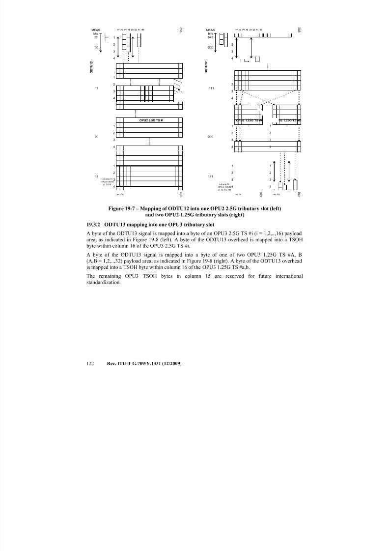
7/16/2019 G-709 ITU_T
http://slidepdf.com/reader/full/g-709-itut 130/218
122 Rec. ITU-T G.709/Y.1331 (12/2009)
1
2
3
4
OPU2 2.5G TS #i
O D T U
1 2
00
11
MFASbits78
00
11
1 2 9 5 2
1 2 9 5 2
1
2
3
4
3 4 5 8 6 7
1
2
3
4
1
2
3
4
1
2
3
4
OPU2 1.25G TS #A
O D T U
1 2
000
111
MFASbits678
000
111
1 2 4 7 6
1 2 9 5 2
1
2
3
4
3 4 5 8 6 7
1
2
3
4
1
2
3
4
OPU2 1.25G TS #B
1 2 4 7 6
1
2
3
4
1
2
3
4
Column 16
OPU2 TSOHof TS #i column 16
OPU2 TSOH
of TS #A, #B
Figure 19-7 – Mapping of ODTU12 into one OPU2 2.5G tributary slot (left)
and two OPU2 1.25G tributary slots (right)
19.3.2 ODTU13 mapping into one OPU3 tributary slot
A byte of the ODTU13 signal is mapped into a byte of an OPU3 2.5G TS #i (i = 1,2,..,16) payload
area, as indicated in Figure 19-8 (left). A byte of the ODTU13 overhead is mapped into a TSOH
byte within column 16 of the OPU3 2.5G TS #i.
A byte of the ODTU13 signal is mapped into a byte of one of two OPU3 1.25G TS #A, B
(A,B = 1,2,..,32) payload area, as indicated in Figure 19-8 (right). A byte of the ODTU13 overhead
is mapped into a TSOH byte within column 16 of the OPU3 1.25G TS #a,b.
The remaining OPU3 TSOH bytes in column 15 are reserved for future international
standardization.
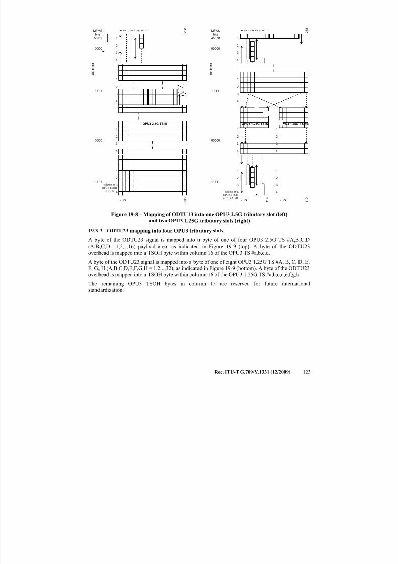
7/16/2019 G-709 ITU_T
http://slidepdf.com/reader/full/g-709-itut 131/218
Rec. ITU-T G.709/Y.1331 (12/2009) 123
1
2
3
4
OPU3 2.5G TS #i
O D T U
1 3
0000
1111
MFASbits
5678
0000
1111
1 2 2 3 8
1 2 2 3 8
1
2
3
4
3 4 5 8 6 7
1
2
3
4
1
2
3
4
1
2
3
4
OPU3 1.25G TS #A
O D T U
1 3
00000
11111
MFASbits
45678
00000
11111
1 2 1 1 9
1 2 2 3 8
1
2
3
4
3 4 5 8 6 7
1
2
3
4
1
2
3
4
OPU3 1.25G TS #B
1 2 1 1 9
1
2
3
4
1
2
3
4
column 16
OPU3 TSOH
of TS #i column 16
OPU3 TSOH
of TS #A, #B
Figure 19-8 – Mapping of ODTU13 into one OPU3 2.5G tributary slot (left)
and two OPU3 1.25G tributary slots (right)
19.3.3 ODTU23 mapping into four OPU3 tributary slots
A byte of the ODTU23 signal is mapped into a byte of one of four OPU3 2.5G TS #A,B,C,D
(A,B,C,D = 1,2,..,16) payload area, as indicated in Figure 19-9 (top). A byte of the ODTU23
overhead is mapped into a TSOH byte within column 16 of the OPU3 TS #a,b,c,d.
A byte of the ODTU23 signal is mapped into a byte of one of eight OPU3 1.25G TS #A, B, C, D, E,
F, G, H (A,B,C,D,E,F,G,H = 1,2,..,32), as indicated in Figure 19-9 (bottom). A byte of the ODTU23
overhead is mapped into a TSOH byte within column 16 of the OPU3 1.25G TS #a,b,c,d,e,f,g,h.
The remaining OPU3 TSOH bytes in column 15 are reserved for future international
standardization.
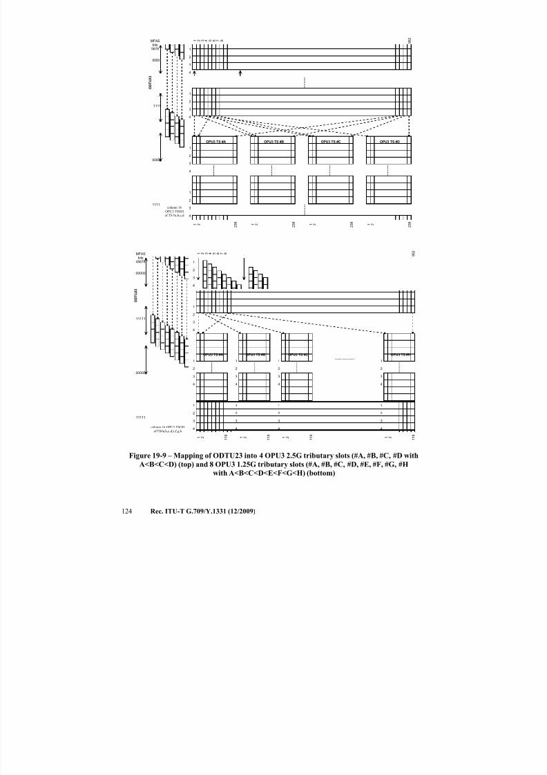
7/16/2019 G-709 ITU_T
http://slidepdf.com/reader/full/g-709-itut 132/218
124 Rec. ITU-T G.709/Y.1331 (12/2009)
1
2
3
4
OPU3 TS #A OPU3 TS #B OPU3 TS #C OPU3 TS #D
O D T U 2 3
0000
1111
MFASbits
5678
0000
1111
1 2 2 3 8
1 2 2 3 8
1 2 2 3 8
1 2 2 3 8
1 2 9 5 2
1
2
3
4
3 4 5 8 6 7
1
2
3
4
1
2
3
4
1
2
3
4
OPU3 TS #A
O D T U 2 3
00000
11111
MFASbits
45678
00000
11111
1 2 1 1 9
1 2 9 5 2
1
2
3
4
3 4 5 8 6 7
1
2
3
4
1
2
3
4
OPU3 TS #B
1 2 1 1 9
1
2
3
4
1
2
3
4
OPU3 TS #C
1 2 1 1 9
1
2
3
4
1
2
3
4
OPU3 TS #H
1 2 1 1 9
1
2
3
4
1
2
3
4
column 16 OPU3 TSOHof TS#a,b,c,d,e,f,g,h
column 16OPU3 TSOHof TS #a,b,c,d
Figure 19-9 – Mapping of ODTU23 into 4 OPU3 2.5G tributary slots (#A, #B, #C, #D with
A<B<C<D) (top) and 8 OPU3 1.25G tributary slots (#A, #B, #C, #D, #E, #F, #G, #H
with A<B<C<D<E<F<G<H) (bottom)
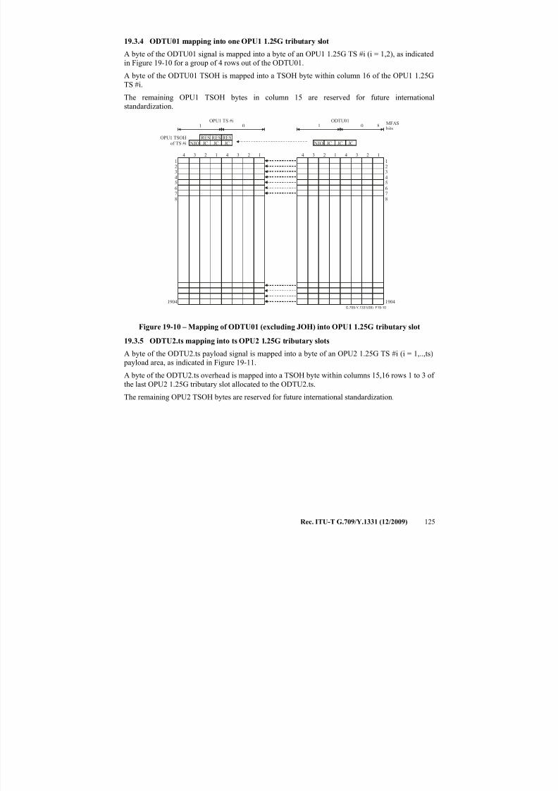
7/16/2019 G-709 ITU_T
http://slidepdf.com/reader/full/g-709-itut 133/218
Rec. ITU-T G.709/Y.1331 (12/2009) 125
19.3.4 ODTU01 mapping into one OPU1 1.25G tributary slot
A byte of the ODTU01 signal is mapped into a byte of an OPU1 1.25G TS #i (i = 1,2), as indicated
in Figure 19-10 for a group of 4 rows out of the ODTU01.
A byte of the ODTU01 TSOH is mapped into a TSOH byte within column 16 of the OPU1 1.25G
TS #i.
The remaining OPU1 TSOH bytes in column 15 are reserved for future internationalstandardization.
4 3 2 1 4 3 2 1
G.709-Y.1331(09)_F19-10
12345678
1904
4 3 2 1 4 3 2 1
12345678
1904
RESJC JC JC JC NJO NJOJC
RESJC
RES
1 0 01
OPU1 TSOHof TS #i
MFAS bits
OPU1 TS #i ODTU018
Figure 19-10 – Mapping of ODTU01 (excluding JOH) into OPU1 1.25G tributary slot
19.3.5 ODTU2.ts mapping into ts OPU2 1.25G tributary slots
A byte of the ODTU2.ts payload signal is mapped into a byte of an OPU2 1.25G TS #i (i = 1,..,ts)
payload area, as indicated in Figure 19-11.
A byte of the ODTU2.ts overhead is mapped into a TSOH byte within columns 15,16 rows 1 to 3 of
the last OPU2 1.25G tributary slot allocated to the ODTU2.ts.
The remaining OPU2 TSOH bytes are reserved for future international standardization.
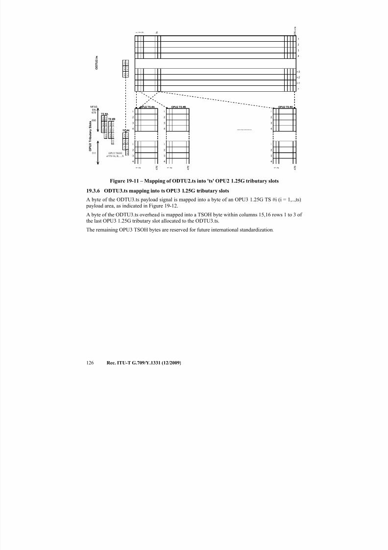
7/16/2019 G-709 ITU_T
http://slidepdf.com/reader/full/g-709-itut 134/218
126 Rec. ITU-T G.709/Y.1331 (12/2009)
OPU2 TS #A
O D
T U 2 . t s
MFASbits678
000
111
1 2 4 7 6
1 2 4 7 6 x t s
3 t s
1
2
3
4
1
2
3
4
OPU2 TS #B
1 2 4 7 6
1
2
3
4
1
2
3
4
OPU2 TS #X
1 2 4 7 6
1
2
3
4
1
2
3
4
r-3
r-2
r-1
r
1
2
3
4
J C 4 J C 1
J C 5 J C 2
J C 6 J C 3
O P U 2 T r i b u t a
r y S l o t s
OPU2 TSOH
of TS #A, B, .., X
TS #A
TS #B
TS #X
R E S
R E S
R E S
R E S
R E S
R E S
R E S
R E S
R E S
R E S
R E S
R E S
R E S
R E S
R E S
J C 4 J C 1
J C 5 J C 2
J C 6 J C 3
Figure 19-11 – Mapping of ODTU2.ts into 'ts' OPU2 1.25G tributary slots
19.3.6 ODTU3.ts mapping into ts OPU3 1.25G tributary slots
A byte of the ODTU3.ts payload signal is mapped into a byte of an OPU3 1.25G TS #i (i = 1,..,ts) payload area, as indicated in Figure 19-12.
A byte of the ODTU3.ts overhead is mapped into a TSOH byte within columns 15,16 rows 1 to 3 of
the last OPU3 1.25G tributary slot allocated to the ODTU3.ts.
The remaining OPU3 TSOH bytes are reserved for future international standardization.

7/16/2019 G-709 ITU_T
http://slidepdf.com/reader/full/g-709-itut 135/218
Rec. ITU-T G.709/Y.1331 (12/2009) 127
OPU3 TS #A
O D T U 3 . t s
MFASbits
45678
00000
11111
1 2 1 1 9
1 2 1 1 9 x t s
3 t s
1
2
3
4
1
2
3
4
OPU3 TS #B
1 2 1 1 9
1
2
3
4
1
2
3
4
OPU3 TS #X
1 2 1 1 9
1
2
3
4
1
2
3
4
r-3
r-2
r-1
r
1
2
3
4
J C 4 J C 1
J C 5 J C 2
J C 6 J C 3
O P U 3 T r i b u t a
r y S l o t s
R E S
R E S
R E S
R E S
R E S
R E S
TS #A
TS #B
OPU3 TSOHof TS # a,b,.., x
R E
S
R E
S
R E S
R E S
R E S
R E S
TS #X
R E S
R E S
R E S
J C 4 J C 1
J C 5 J C 2
J C 6 J C 3
Figure 19-12 – Mapping of ODTU3.ts into 'ts' OPU3 1.25G tributary slots
19.3.7 ODTU4.ts mapping into ts OPU4 1.25G tributary slots
A byte of the ODTU4.ts payload signal is mapped into a byte of an OPU4 1.25G TS #i (i = 1,..,ts) payload area, as indicated in Figure 19-13.
A byte of the ODTU4.ts overhead is mapped into a TSOH byte within columns 15,16 rows 1 to 3 of
the last OPU4 1.25G tributary slot allocated to the ODTU4.ts.
The remaining OPU4 TSOH bytes are reserved for future international standardization.
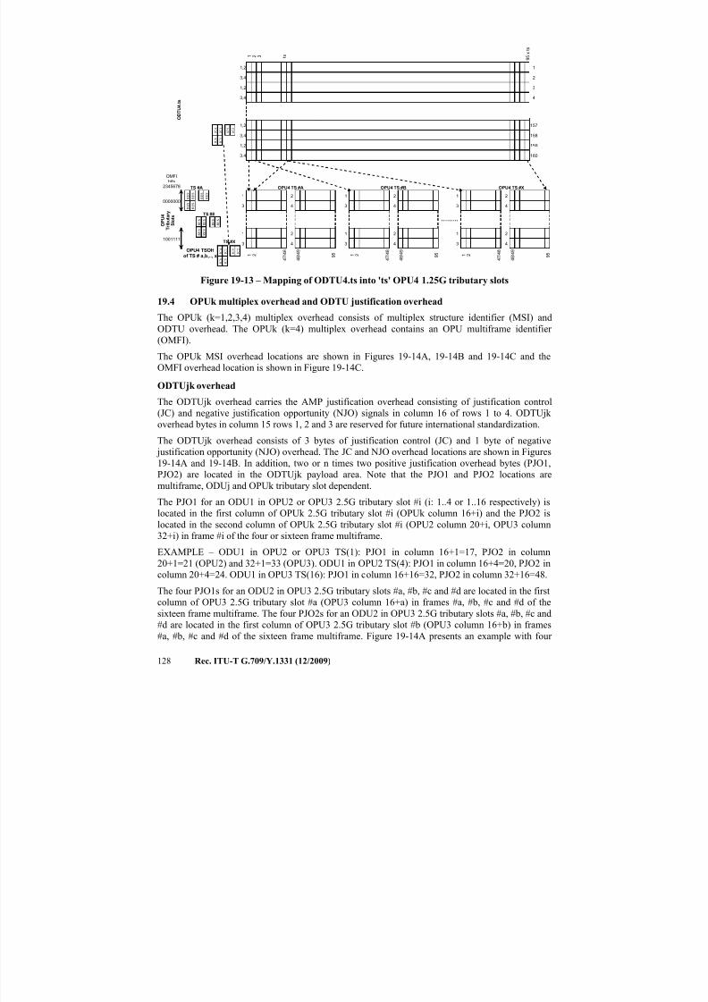
7/16/2019 G-709 ITU_T
http://slidepdf.com/reader/full/g-709-itut 136/218
128 Rec. ITU-T G.709/Y.1331 (12/2009)
1,2
3,4
1,2
3,4
OPU4 TS #A
O D T U 4 . t s
OMFIbits
2345678
0000000
1001111
1 2 4 7 / 4 8
1 2 9 5 x
t s
1,2
3,4
1,2
3,4
3 t s
1
3
1 2
3 4
OPU4 TS #X
157
158
159
160
1
2
3
4
R E S
R E S
R E S
R E S
R E S
R E S
R E S
R E S
R E S
R E S
R E S
R E S
J C 4 J C 1
J C 6 J C 3
J C 5 J C 2
O P U 4
T r i b u t a r y
S l o t s
2
4
4 8 / 4 9
9 5
OPU4 TS #B
1 2 4 7 / 4 8
1
3
1 2
3 4
2
4
4 8 / 4 9
9 5
TS #A
TS #B
TS #X
1 2 4 7 / 4 8
1
3
1 2
3 4
2
4
4 8 / 4 9
9 5
OPU4 TSOHof TS # a,b,.., x
J C 4 J C 1
J C 6 J C 3
J C 5 J C 2
Figure 19-13 – Mapping of ODTU4.ts into 'ts' OPU4 1.25G tributary slots
19.4 OPUk multiplex overhead and ODTU justification overhead
The OPUk (k=1,2,3,4) multiplex overhead consists of multiplex structure identifier (MSI) and
ODTU overhead. The OPUk (k=4) multiplex overhead contains an OPU multiframe identifier
(OMFI).
The OPUk MSI overhead locations are shown in Figures 19-14A, 19-14B and 19-14C and the
OMFI overhead location is shown in Figure 19-14C.
ODTUjk overhead
The ODTUjk overhead carries the AMP justification overhead consisting of justification control
(JC) and negative justification opportunity (NJO) signals in column 16 of rows 1 to 4. ODTUjk
overhead bytes in column 15 rows 1, 2 and 3 are reserved for future international standardization.
The ODTUjk overhead consists of 3 bytes of justification control (JC) and 1 byte of negative
justification opportunity (NJO) overhead. The JC and NJO overhead locations are shown in Figures
19-14A and 19-14B. In addition, two or n times two positive justification overhead bytes (PJO1,
PJO2) are located in the ODTUjk payload area. Note that the PJO1 and PJO2 locations are
multiframe, ODUj and OPUk tributary slot dependent.
The PJO1 for an ODU1 in OPU2 or OPU3 2.5G tributary slot #i (i: 1..4 or 1..16 respectively) is
located in the first column of OPUk 2.5G tributary slot #i (OPUk column 16+i) and the PJO2 is
located in the second column of OPUk 2.5G tributary slot #i (OPU2 column 20+i, OPU3 column
32+i) in frame #i of the four or sixteen frame multiframe.
EXAMPLE – ODU1 in OPU2 or OPU3 TS(1): PJO1 in column 16+1=17, PJO2 in column
20+1=21 (OPU2) and 32+1=33 (OPU3). ODU1 in OPU2 TS(4): PJO1 in column 16+4=20, PJO2 in
column 20+4=24. ODU1 in OPU3 TS(16): PJO1 in column 16+16=32, PJO2 in column 32+16=48.
The four PJO1s for an ODU2 in OPU3 2.5G tributary slots #a, #b, #c and #d are located in the first
column of OPU3 2.5G tributary slot #a (OPU3 column 16+a) in frames #a, #b, #c and #d of the
sixteen frame multiframe. The four PJO2s for an ODU2 in OPU3 2.5G tributary slots #a, #b, #c and
#d are located in the first column of OPU3 2.5G tributary slot #b (OPU3 column 16+b) in frames
#a, #b, #c and #d of the sixteen frame multiframe. Figure 19-14A presents an example with four
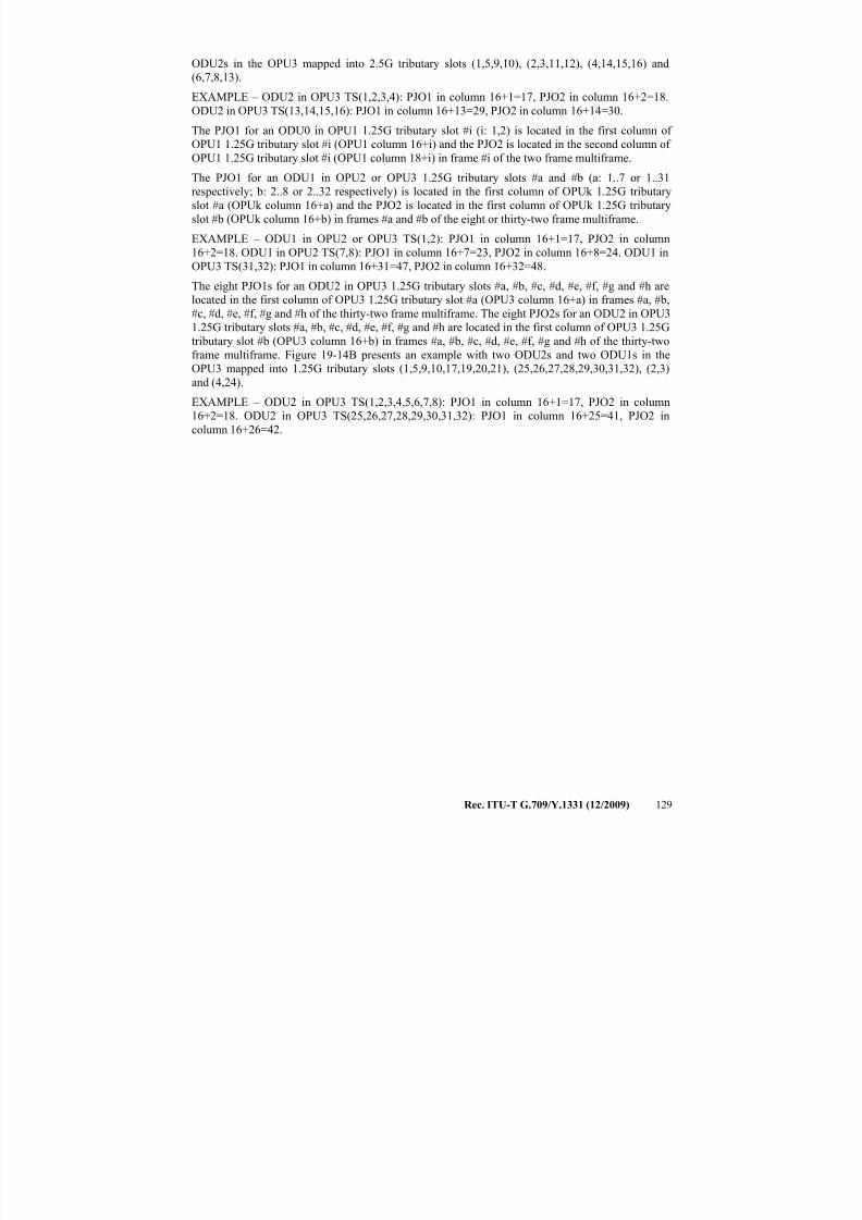
7/16/2019 G-709 ITU_T
http://slidepdf.com/reader/full/g-709-itut 137/218
Rec. ITU-T G.709/Y.1331 (12/2009) 129
ODU2s in the OPU3 mapped into 2.5G tributary slots (1,5,9,10), (2,3,11,12), (4,14,15,16) and
(6,7,8,13).
EXAMPLE – ODU2 in OPU3 TS(1,2,3,4): PJO1 in column 16+1=17, PJO2 in column 16+2=18.
ODU2 in OPU3 TS(13,14,15,16): PJO1 in column 16+13=29, PJO2 in column 16+14=30.
The PJO1 for an ODU0 in OPU1 1.25G tributary slot #i (i: 1,2) is located in the first column of
OPU1 1.25G tributary slot #i (OPU1 column 16+i) and the PJO2 is located in the second column of OPU1 1.25G tributary slot #i (OPU1 column 18+i) in frame #i of the two frame multiframe.
The PJO1 for an ODU1 in OPU2 or OPU3 1.25G tributary slots #a and #b (a: 1..7 or 1..31
respectively; b: 2..8 or 2..32 respectively) is located in the first column of OPUk 1.25G tributary
slot #a (OPUk column 16+a) and the PJO2 is located in the first column of OPUk 1.25G tributary
slot #b (OPUk column 16+b) in frames #a and #b of the eight or thirty-two frame multiframe.
EXAMPLE – ODU1 in OPU2 or OPU3 TS(1,2): PJO1 in column 16+1=17, PJO2 in column
16+2=18. ODU1 in OPU2 TS(7,8): PJO1 in column 16+7=23, PJO2 in column 16+8=24. ODU1 in
OPU3 TS(31,32): PJO1 in column 16+31=47, PJO2 in column 16+32=48.
The eight PJO1s for an ODU2 in OPU3 1.25G tributary slots #a, #b, #c, #d, #e, #f, #g and #h are
located in the first column of OPU3 1.25G tributary slot #a (OPU3 column 16+a) in frames #a, #b,#c, #d, #e, #f, #g and #h of the thirty-two frame multiframe. The eight PJO2s for an ODU2 in OPU3
1.25G tributary slots #a, #b, #c, #d, #e, #f, #g and #h are located in the first column of OPU3 1.25G
tributary slot #b (OPU3 column 16+b) in frames #a, #b, #c, #d, #e, #f, #g and #h of the thirty-two
frame multiframe. Figure 19-14B presents an example with two ODU2s and two ODU1s in the
OPU3 mapped into 1.25G tributary slots (1,5,9,10,17,19,20,21), (25,26,27,28,29,30,31,32), (2,3)
and (4,24).
EXAMPLE – ODU2 in OPU3 TS(1,2,3,4,5,6,7,8): PJO1 in column 16+1=17, PJO2 in column
16+2=18. ODU2 in OPU3 TS(25,26,27,28,29,30,31,32): PJO1 in column 16+25=41, PJO2 in
column 16+26=42.
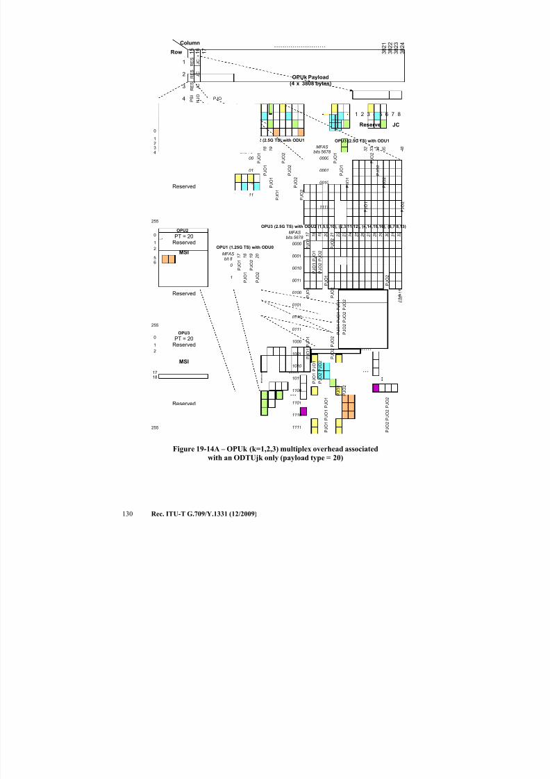
7/16/2019 G-709 ITU_T
http://slidepdf.com/reader/full/g-709-itut 138/218
130 Rec. ITU-T G.709/Y.1331 (12/2009)
J C
N J O
1
2
3
4
1 6
1 7
3 8 2 4
Row
Column
OPUk Payload(4 x 3808 bytes)
3 8 2 3
3 8 2 2
3 8 2 1
1 5
P S I
J C
J C
JCReserved
1 6 7 82 543
JC
0
1
2
56
255
Reserved
MSI
Reserved
1 7
2 1
1 8
1 9
2 0
2 2
2 3
2 4
00
01
10
11
P J O 1
P J O 2
1 7
3 3
1 8
1 9
3 2
3 4
3 5
4 8
0000
0001
0010
1111
PJO
MF AS
bits 78
MFAS
bits 5678
OPU2 (2.5G TS) with ODU1 OPU3 (2.5G TS) with ODU1
P J O 1
P J O 2
P J O 1
P J O 2
P J O 1
P J O 2
1 7
2 1
1 8
1 9
2 0
2 2
2 3
2 4
0000
0001
0010
MFAS
bits 5678
OPU3 (2.5G TS) with ODU2 (1,5,9,10), (2,3,11,12), (4,14,15,16), (6,7,8,13)
2 5
2 9
2 6
2 7
2 8
3 0
3 1
3 2
P J O 1
P J O 2
P J O 1
P J O 2
0011
0100
0101
P J O 1
P J O 2
P J O 1
P J O 2
P J O 1
P J O 2
P J O 1
P J O 2
0110
0111
1000
P J O 1
P J O 2
P J O 1
P J O 2
P J O
1
P J O
2
1001
1010
1011
P J O 1
P J O 1
P J O 2
P J O 1
1100
1101
1110
P J O 2
P J O 2
P J O 1
1111 P J O 2
0
1
2
17
18
255
Reserved
MSI
Reserved
OPU3
OPU2
0
1234
255
Reserved
MSI
Reserved
OPU1
1 7
1 8
1 9
2 0
0
1
MFAS
bit 8
OPU1 (1.25G TS) with ODU0
P J O 1
P J O 2
P J O 1
P J O 2
P J O 1
P J O 2
P J O 1
P J O 2
P J O 1
P J O 1
P J O 1
P J O 2
P J O 2
P J O 2
P J O 1
P J O 2
P J O 1
P J O 2
R E S
R E S
R E S
PT = 20
PT = 20
PT = 20
Figure 19-14A – OPUk (k=1,2,3) multiplex overhead associated
with an ODTUjk only (payload type = 20)
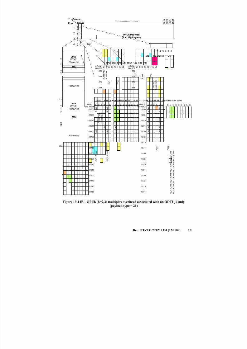
7/16/2019 G-709 ITU_T
http://slidepdf.com/reader/full/g-709-itut 139/218
Rec. ITU-T G.709/Y.1331 (12/2009) 131
J C
N J O
1
2
3
4
1 6
1 7
3 8 2 4
Row
Column
OPUk Payload(4 x 3808 bytes)
3 8 2 3
3 8 2 2
3 8 2 1
1 5
P S I
J C
J C
JCReserved
1 6 7 82 543
JC
1 7
1 8
1 9
2 0
000
001
010
PJO
MFAS
bits 678
OPU2 (1.25G TS) with ODU1 (1,2), (3,6), (7,8)
P J O 1
P J O 2
P J O 1
P J O 2
P J O 1
P J O 2
1 7
2 1
1 8
1 9
2 0
2 2
4 0
4 1
00000
00001
00010
MFAS
bits 45678
OPU3 (1.25G TS) with ODU2 (1,5,9,10,17,19,20,21), (25,26,27,28,29,30,31,32),ODU1 (2,3), (4,24)
4 2
4 6
4 3
4 4
4 5
4 7 :
4 8
P J O 1
P J O 2
00011
00100
00101
P J O 1
P J O 1
P J O 2
00110
00111
01000
P J O 1
P J O 2
01001
01010
01011
P J O 1
P J O
1
01100
01101
01110
P J O 2
P J O
2
P J O 1
01111
P J O 2
P J O 1
R E S
R E S
R E S
0
1
2
3334
255
Reserved
MSI
Reserved
OPU3
0
12
910
255
Reserved
MSI
Reserved
OPU2
PT=21
PT=21
2 1
2 2
2 3
2 4
P J O 2
P J O 1
P J O 2
011
P J O 1
P J O 2
10000
10001
10010
P J O 1
P J O 2
10011
10100
10101
P J O 1
P J O 2
P J O 1
P J O 2
P J
O 1
P J
O 2
P J
O 1
P J
O 2
10110
10111
11000
P J O 1
P J O 2
11001
11010
11011
P J O 1
P J O 1
11100
11101
11110
P J O 2
P J O 2
P J O 1
11111
P J O 2
P J O 2
1 7
2 1
1 8
1 9
2 0
2 2
4 0
4 1
4 2
4 6
4 3
4 4
4 5
4 7 :
4 8MFAS
bits 45678
P J O 1
P J O 2
P J O 1
P J O 2
P J O 1
P J O 2
1 7
1 8
1 9
2 0
100
101
110
MFAS
bits 678 2
1 2 2
2 3
2 4
P J O 1
P J O 2
111
Figure 19-14B – OPUk (k=2,3) multiplex overhead associated with an ODTUjk only
(payload type = 21)
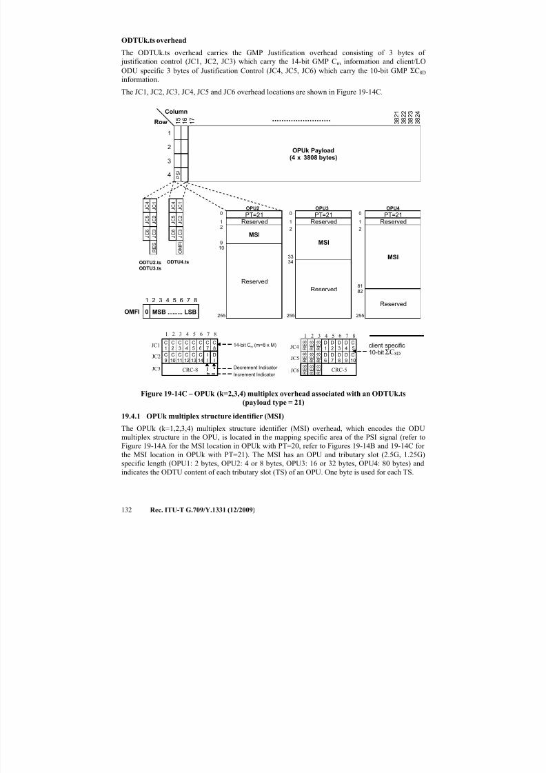
7/16/2019 G-709 ITU_T
http://slidepdf.com/reader/full/g-709-itut 140/218
132 Rec. ITU-T G.709/Y.1331 (12/2009)
ODTUk.ts overhead
The ODTUk.ts overhead carries the GMP Justification overhead consisting of 3 bytes of
justification control (JC1, JC2, JC3) which carry the 14-bit GMP Cm information and client/LO
ODU specific 3 bytes of Justification Control (JC4, JC5, JC6) which carry the 10-bit GMP ΣC8D
information.
The JC1, JC2, JC3, JC4, JC5 and JC6 overhead locations are shown in Figure 19-14C.
1
2
3
4
1 6
1 7
3 8 2 4
Row
Column
OPUk Payload(4 x 3808 bytes)
3 8 2 3
3 8 2 2
3 8 2 1
1 5
P S I
0
1
2
3334
255
Reserved
MSI
Reserved
0
1
2
8182
255
Reserved
MSI
Reserved
OPU4OPU30
12
910
255
Reserved
MSI
Reserved
OPU2
PT=21 PT=21 PT=21
MSB ......... LSB
1 6 7 82 543
OMFI 0
ODTU2.ts
ODTU3.ts
ODTU4.ts
1 6 7 82 543
JC1
CRC-8
JC2
JC3
C9
C10
C11
C12
C13
C14
II
DI
C1
C2
C3
C4
C5
C6
C7
C8
Increment Indicator
Decrement Indicator
14-bit Cm (m=8 x M)
J C 1
J C 2
J C 3
J C 4
J C 5
J C 6
O M F I
J C 1
J C 2
J C 3
J C 4
J C 5
J C 6
R E S
1 6 7 82 543
JC4
JC5
JC6
client specific10-bit
CRC-5
R E SD
6D7
D8
D9
D10
R E S
R E S
R E SD
1D2
D3
D4
D5
R E S
R E S ΣC8D
R E S
R E S
R E S
Figure 19-14C – OPUk (k=2,3,4) multiplex overhead associated with an ODTUk.ts
(payload type = 21)
19.4.1 OPUk multiplex structure identifier (MSI)
The OPUk (k=1,2,3,4) multiplex structure identifier (MSI) overhead, which encodes the ODU
multiplex structure in the OPU, is located in the mapping specific area of the PSI signal (refer to
Figure 19-14A for the MSI location in OPUk with PT=20, refer to Figures 19-14B and 19-14C for
the MSI location in OPUk with PT=21). The MSI has an OPU and tributary slot (2.5G, 1.25G)
specific length (OPU1: 2 bytes, OPU2: 4 or 8 bytes, OPU3: 16 or 32 bytes, OPU4: 80 bytes) and
indicates the ODTU content of each tributary slot (TS) of an OPU. One byte is used for each TS.
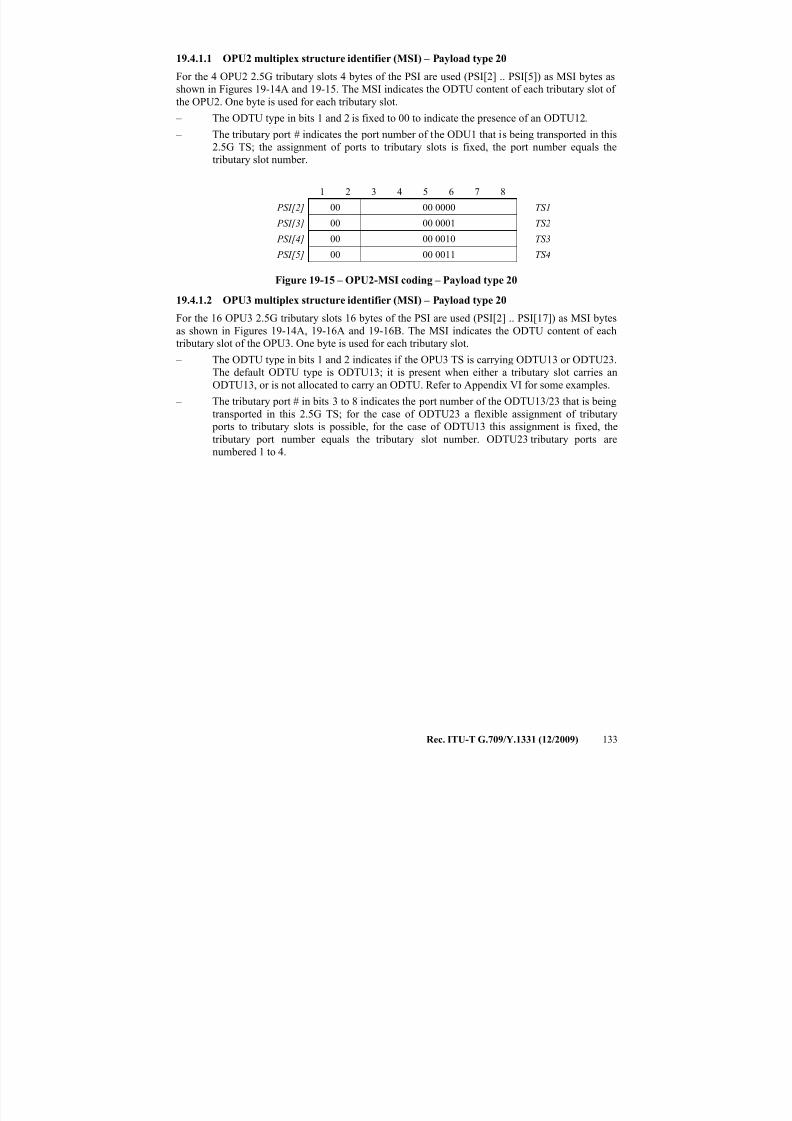
7/16/2019 G-709 ITU_T
http://slidepdf.com/reader/full/g-709-itut 141/218
Rec. ITU-T G.709/Y.1331 (12/2009) 133
19.4.1.1 OPU2 multiplex structure identifier (MSI) – Payload type 20
For the 4 OPU2 2.5G tributary slots 4 bytes of the PSI are used (PSI[2] .. PSI[5]) as MSI bytes as
shown in Figures 19-14A and 19-15. The MSI indicates the ODTU content of each tributary slot of
the OPU2. One byte is used for each tributary slot.
– The ODTU type in bits 1 and 2 is fixed to 00 to indicate the presence of an ODTU12.
– The tributary port # indicates the port number of the ODU1 that is being transported in this2.5G TS; the assignment of ports to tributary slots is fixed, the port number equals the
tributary slot number.
1 2 3 4 5 6 7 8
PSI[2] 00 00 0000 TS1
PSI[3] 00 00 0001 TS2
PSI[4] 00 00 0010 TS3
PSI[5] 00 00 0011 TS4
Figure 19-15 – OPU2-MSI coding – Payload type 20
19.4.1.2 OPU3 multiplex structure identifier (MSI) – Payload type 20
For the 16 OPU3 2.5G tributary slots 16 bytes of the PSI are used (PSI[2] .. PSI[17]) as MSI bytes
as shown in Figures 19-14A, 19-16A and 19-16B. The MSI indicates the ODTU content of each
tributary slot of the OPU3. One byte is used for each tributary slot.
– The ODTU type in bits 1 and 2 indicates if the OPU3 TS is carrying ODTU13 or ODTU23.
The default ODTU type is ODTU13; it is present when either a tributary slot carries an
ODTU13, or is not allocated to carry an ODTU. Refer to Appendix VI for some examples.
– The tributary port # in bits 3 to 8 indicates the port number of the ODTU13/23 that is being
transported in this 2.5G TS; for the case of ODTU23 a flexible assignment of tributary
ports to tributary slots is possible, for the case of ODTU13 this assignment is fixed, the
tributary port number equals the tributary slot number. ODTU23 tributary ports are
numbered 1 to 4.
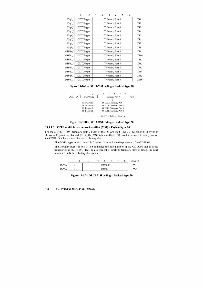
7/16/2019 G-709 ITU_T
http://slidepdf.com/reader/full/g-709-itut 142/218
134 Rec. ITU-T G.709/Y.1331 (12/2009)
1 2 3 4 5 6 7 8
PSI[2] ODTU type Tributary Port # TS1
PSI[3] ODTU type Tributary Port # TS2
PSI[4] ODTU type Tributary Port # TS3
PSI[5] ODTU type Tributary Port # TS4
PSI[6] ODTU type Tributary Port # TS5
PSI[7] ODTU type Tributary Port # TS6
PSI[8] ODTU type Tributary Port # TS7
PSI[9] ODTU type Tributary Port # TS8
PSI[10] ODTU type Tributary Port # TS9
PSI[11] ODTU type Tributary Port # TS10
PSI[12] ODTU type Tributary Port # TS11
PSI[13] ODTU type Tributary Port # TS12
PSI[14] ODTU type Tributary Port # TS13
PSI[15] ODTU type Tributary Port # TS14
PSI[16] ODTU type Tributary Port # TS15
PSI[17] ODTU type Tributary Port # TS16
Figure 19-16A – OPU3-MSI coding – Payload type 20
1 2 3 4 5 6 7 8
PSI[1+ i] ODTU type Tributary Port # TS #i
00: ODTU13
01: ODTU23
10: Reserved
11: Reserved
00 0000: Tributary Port 1
00 0001: Tributary Port 2
00 0010: Tributary Port 3
00 0011: Tributary Port 4
:
00 1111: Tributary Port 16
Figure 19-16B – OPU3 MSI coding – Payload type 20
19.4.1.3 OPU1 multiplex structure identifier (MSI) – Payload type 20
For the 2 OPU1 1.25G tributary slots 2 bytes of the PSI are used (PSI[2], PSI[3]) as MSI bytes as
shown in Figures 19-14A and 19-17. The MSI indicates the ODTU content of each tributary slot of
the OPU1. One byte is used for each tributary slot. – The ODTU type in bits 1 and 2 is fixed to 11 to indicate the presence of an ODTU01.
– The tributary port # in bits 3 to 8 indicates the port number of the ODTU01 that is being
transported in this 1.25G TS; the assignment of ports to tributary slots is fixed, the port
number equals the tributary slot number.
1 2 3 4 5 6 7 8 1.25G TS
PSI[2] 11 00 0000 TS1
PSI[3] 11 00 0001 TS2
Figure 19-17 – OPU1 MSI coding – Payload type 20
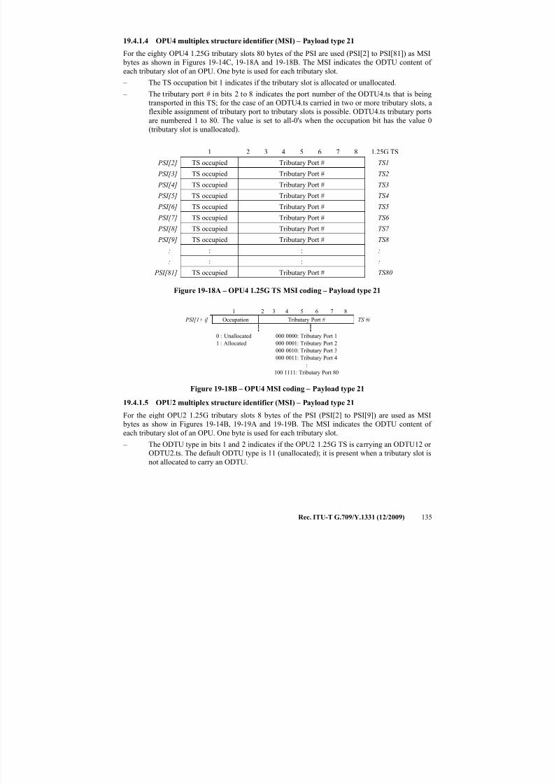
7/16/2019 G-709 ITU_T
http://slidepdf.com/reader/full/g-709-itut 143/218
Rec. ITU-T G.709/Y.1331 (12/2009) 135
19.4.1.4 OPU4 multiplex structure identifier (MSI) – Payload type 21
For the eighty OPU4 1.25G tributary slots 80 bytes of the PSI are used (PSI[2] to PSI[81]) as MSI
bytes as shown in Figures 19-14C, 19-18A and 19-18B. The MSI indicates the ODTU content of
each tributary slot of an OPU. One byte is used for each tributary slot.
– The TS occupation bit 1 indicates if the tributary slot is allocated or unallocated.
– The tributary port # in bits 2 to 8 indicates the port number of the ODTU4.ts that is beingtransported in this TS; for the case of an ODTU4.ts carried in two or more tributary slots, a
flexible assignment of tributary port to tributary slots is possible. ODTU4.ts tributary ports
are numbered 1 to 80. The value is set to all-0's when the occupation bit has the value 0
(tributary slot is unallocated).
1 2 3 4 5 6 7 8 1.25G TS
PSI[2] TS occupied Tributary Port # TS1
PSI[3] TS occupied Tributary Port # TS2
PSI[4] TS occupied Tributary Port # TS3
PSI[5] TS occupied Tributary Port # TS4
PSI[6] TS occupied Tributary Port # TS5
PSI[7] TS occupied Tributary Port # TS6
PSI[8] TS occupied Tributary Port # TS7
PSI[9] TS occupied Tributary Port # TS8
: : : :
: : : :
PSI[81] TS occupied Tributary Port # TS80
Figure 19-18A – OPU4 1.25G TS MSI coding – Payload type 21
1 2 3 4 5 6 7 8
PSI[1+ i] Occupation Tributary Port # TS #i
0 : Unallocated
1 : Allocated
000 0000: Tributary Port 1
000 0001: Tributary Port 2
000 0010: Tributary Port 3
000 0011: Tributary Port 4
:
100 1111: Tributary Port 80
Figure 19-18B – OPU4 MSI coding – Payload type 21
19.4.1.5 OPU2 multiplex structure identifier (MSI) – Payload type 21
For the eight OPU2 1.25G tributary slots 8 bytes of the PSI (PSI[2] to PSI[9]) are used as MSI
bytes as show in Figures 19-14B, 19-19A and 19-19B. The MSI indicates the ODTU content of
each tributary slot of an OPU. One byte is used for each tributary slot.
– The ODTU type in bits 1 and 2 indicates if the OPU2 1.25G TS is carrying an ODTU12 or
ODTU2.ts. The default ODTU type is 11 (unallocated); it is present when a tributary slot is
not allocated to carry an ODTU.
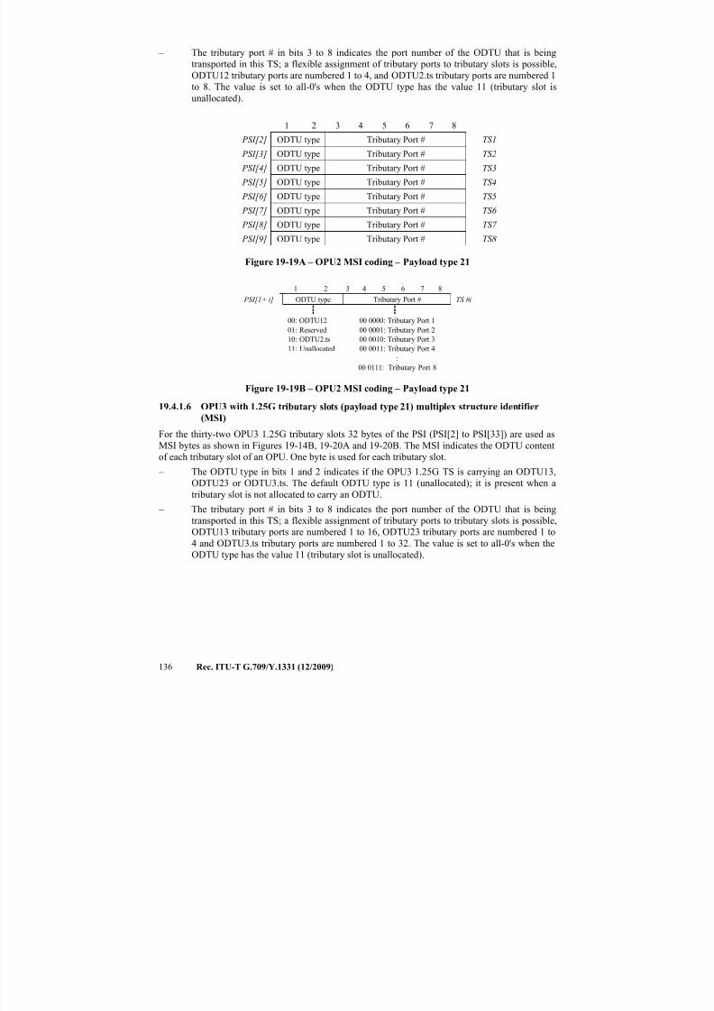
7/16/2019 G-709 ITU_T
http://slidepdf.com/reader/full/g-709-itut 144/218
136 Rec. ITU-T G.709/Y.1331 (12/2009)
– The tributary port # in bits 3 to 8 indicates the port number of the ODTU that is being
transported in this TS; a flexible assignment of tributary ports to tributary slots is possible,
ODTU12 tributary ports are numbered 1 to 4, and ODTU2.ts tributary ports are numbered 1
to 8. The value is set to all-0's when the ODTU type has the value 11 (tributary slot is
unallocated).
1 2 3 4 5 6 7 8
PSI[2] ODTU type Tributary Port # TS1
PSI[3] ODTU type Tributary Port # TS2
PSI[4] ODTU type Tributary Port # TS3
PSI[5] ODTU type Tributary Port # TS4
PSI[6] ODTU type Tributary Port # TS5
PSI[7] ODTU type Tributary Port # TS6
PSI[8] ODTU type Tributary Port # TS7
PSI[9] ODTU type Tributary Port # TS8
Figure 19-19A – OPU2 MSI coding – Payload type 21
1 2 3 4 5 6 7 8
PSI[1+ i] ODTU type Tributary Port # TS #i
00: ODTU12
01: Reserved
10: ODTU2.ts
11: Unallocated
00 0000: Tributary Port 1
00 0001: Tributary Port 2
00 0010: Tributary Port 3
00 0011: Tributary Port 4
:
00 0111: Tributary Port 8
Figure 19-19B – OPU2 MSI coding – Payload type 21
19.4.1.6 OPU3 with 1.25G tributary slots (payload type 21) multiplex structure identifier
(MSI)
For the thirty-two OPU3 1.25G tributary slots 32 bytes of the PSI (PSI[2] to PSI[33]) are used as
MSI bytes as shown in Figures 19-14B, 19-20A and 19-20B. The MSI indicates the ODTU content
of each tributary slot of an OPU. One byte is used for each tributary slot.
– The ODTU type in bits 1 and 2 indicates if the OPU3 1.25G TS is carrying an ODTU13,
ODTU23 or ODTU3.ts. The default ODTU type is 11 (unallocated); it is present when a
tributary slot is not allocated to carry an ODTU.
– The tributary port # in bits 3 to 8 indicates the port number of the ODTU that is being
transported in this TS; a flexible assignment of tributary ports to tributary slots is possible,
ODTU13 tributary ports are numbered 1 to 16, ODTU23 tributary ports are numbered 1 to
4 and ODTU3.ts tributary ports are numbered 1 to 32. The value is set to all-0's when the
ODTU type has the value 11 (tributary slot is unallocated).
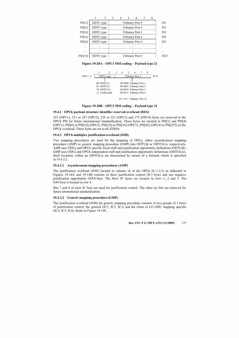
7/16/2019 G-709 ITU_T
http://slidepdf.com/reader/full/g-709-itut 145/218
Rec. ITU-T G.709/Y.1331 (12/2009) 137
1 2 3 4 5 6 7 8
PSI[2] ODTU type Tributary Port # TS1
PSI[3] ODTU type Tributary Port # TS2
PSI[4] ODTU type Tributary Port # TS3
PSI[5] ODTU type Tributary Port # TS4
PSI[6] ODTU type Tributary Port # TS5
: : : :
: : : :
PSI[33] ODTU type Tributary Port # TS32
Figure 19-20A – OPU3 MSI coding – Payload type 21
1 2 3 4 5 6 7 8
PSI[1+ i] ODTU type Tributary Port # TS #i
00: ODTU13
01: ODTU23
10: ODTU3.ts
11: Unallocated
00 0000: Tributary Port 1
00 0001: Tributary Port 2
00 0010: Tributary Port 3
00 0011: Tributary Port 4
:
01 1111: Tributary Port 32
Figure 19-20B – OPU3 MSI coding – Payload type 21
19.4.2 OPUk payload structure identifier reserved overhead (RES)
253 (OPU1), 251 or 247 (OPU2), 239 or 223 (OPU3) and 175 (OPU4) bytes are reserved in the
OPUk PSI for future international standardization. These bytes are located in PSI[1] and PSI[4]
(OPU1), PSI[6] or PSI[10] (OPU2), PSI[18] or PSI[34] (OPU3), PSI[82] (OPU4) to PSI[255] of the
OPUk overhead. These bytes are set to all ZEROs.
19.4.3 OPUk multiplex justification overhead (JOH)
Two mapping procedures are used for the mapping of ODUj, either asynchronous mapping
procedure (AMP) or generic mapping procedure (GMP) into ODTUjk or ODTUk.ts, respectively.
AMP uses ODUj and OPUk specific fixed stuff and justification opportunity definitions (ODTUjk).
GMP uses ODUj and OPUk independent stuff and justification opportunity definitions (ODTUk.ts).
Stuff locations within an ODTUk.ts are determined by means of a formula which is specified
in 19.4.3.2.
19.4.3.1 Asynchronous mapping procedures (AMP)
The justification overhead (JOH) located in column 16 of the OPUk (k=1,2,3) as indicated in
Figures 19-14A and 19-14B consists of three justification control (JC) bytes and one negative
justification opportunity (NJO) byte. The three JC bytes are located in rows 1, 2 and 3. The
NJO byte is located in row 4.
Bits 7 and 8 of each JC byte are used for justification control. The other six bits are reserved for
future international standardization.
19.4.3.2 Generic mapping procedure (GMP)
The justification overhead (JOH) for generic mapping procedure consists of two groups of 3 bytes
of justification control; the general (JC1, JC2, JC3) and the client to LO ODU mapping specific
(JC4, JC5, JC6). Refer to Figure 19-14C.
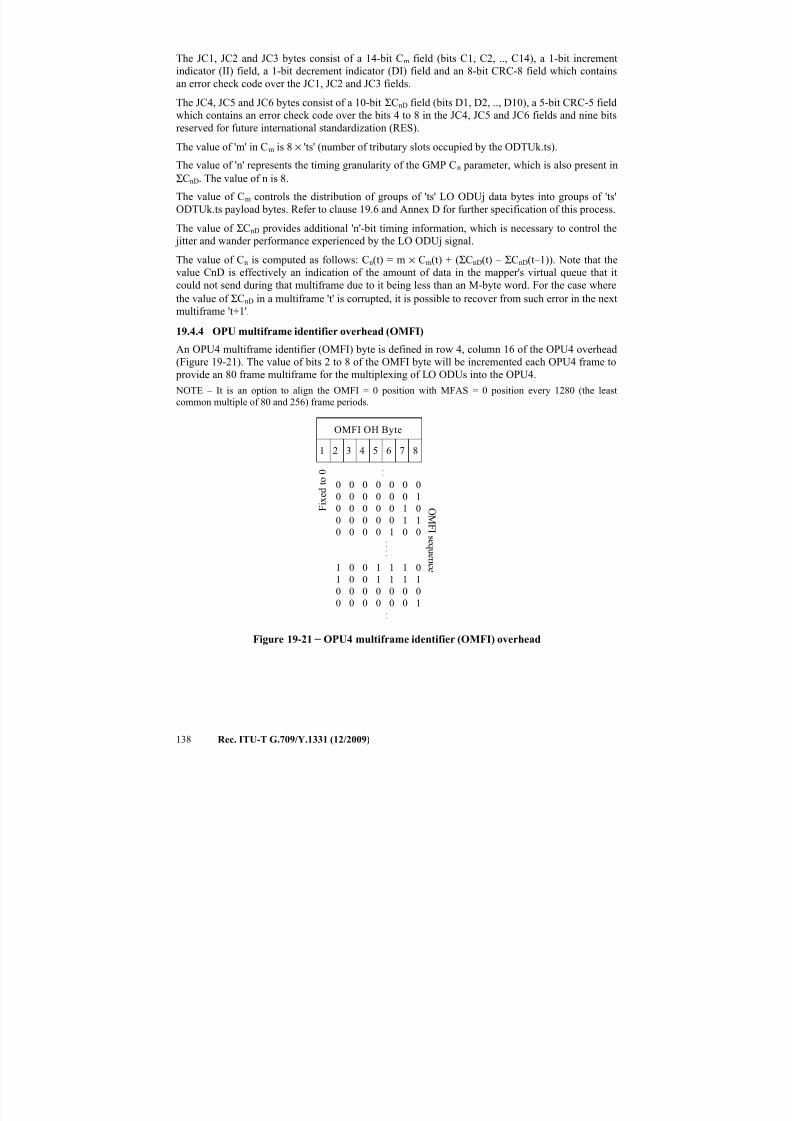
7/16/2019 G-709 ITU_T
http://slidepdf.com/reader/full/g-709-itut 146/218
138 Rec. ITU-T G.709/Y.1331 (12/2009)
The JC1, JC2 and JC3 bytes consist of a 14-bit Cm field (bits C1, C2, .., C14), a 1-bit increment
indicator (II) field, a 1-bit decrement indicator (DI) field and an 8-bit CRC-8 field which contains
an error check code over the JC1, JC2 and JC3 fields.
The JC4, JC5 and JC6 bytes consist of a 10-bit ΣCnD field (bits D1, D2, .., D10), a 5-bit CRC-5 field
which contains an error check code over the bits 4 to 8 in the JC4, JC5 and JC6 fields and nine bits
reserved for future international standardization (RES).
The value of 'm' in Cm is 8 × 'ts' (number of tributary slots occupied by the ODTUk.ts).
The value of 'n' represents the timing granularity of the GMP Cn parameter, which is also present in
ΣCnD. The value of n is 8.
The value of Cm controls the distribution of groups of 'ts' LO ODUj data bytes into groups of 'ts'
ODTUk.ts payload bytes. Refer to clause 19.6 and Annex D for further specification of this process.
The value of ΣCnD provides additional 'n'-bit timing information, which is necessary to control the
jitter and wander performance experienced by the LO ODUj signal.
The value of Cn is computed as follows: Cn(t) = m × Cm(t) + (ΣCnD(t) – ΣCnD(t–1)). Note that the
value CnD is effectively an indication of the amount of data in the mapper's virtual queue that itcould not send during that multiframe due to it being less than an M-byte word. For the case where
the value of ΣCnD in a multiframe 't' is corrupted, it is possible to recover from such error in the next
multiframe 't+1'.
19.4.4 OPU multiframe identifier overhead (OMFI)
An OPU4 multiframe identifier (OMFI) byte is defined in row 4, column 16 of the OPU4 overhead
(Figure 19-21). The value of bits 2 to 8 of the OMFI byte will be incremented each OPU4 frame to
provide an 80 frame multiframe for the multiplexing of LO ODUs into the OPU4.
NOTE – It is an option to align the OMFI = 0 position with MFAS = 0 position every 1280 (the least
common multiple of 80 and 256) frame periods.
1 2 3 4 5 6 7 8
0 0 0 0 0 0 0
0 0 0 0 0 0 1
0 0 0 0 0 1 0
0 0 0 0 0 1 1
0 0 0 0 1 0 0....
.
.
1 0 0 1 1 1 0
1 0 0 1 1 1 1
0 0 0 0 0 0 0
0 0 0 0 0 0 1..
OMFI OH Byte
OMF I
s e q u e n c e
F i x e d t o 0
Figure 19-21 − OPU4 multiframe identifier (OMFI) overhead
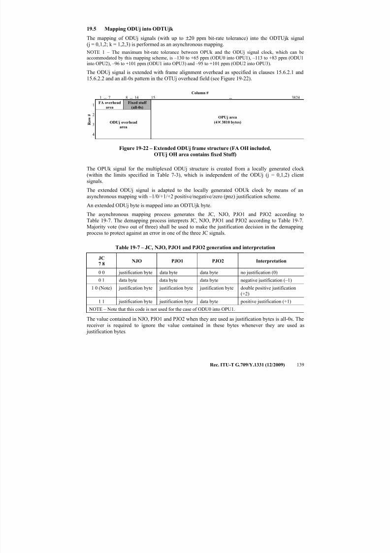
7/16/2019 G-709 ITU_T
http://slidepdf.com/reader/full/g-709-itut 147/218
Rec. ITU-T G.709/Y.1331 (12/2009) 139
19.5 Mapping ODUj into ODTUjk
The mapping of ODUj signals (with up to ±20 ppm bit-rate tolerance) into the ODTUjk signal
(j = 0,1,2; k = 1,2,3) is performed as an asynchronous mapping.
NOTE 1 – The maximum bit-rate tolerance between OPUk and the ODUj signal clock, which can be
accommodated by this mapping scheme, is –130 to +65 ppm (ODU0 into OPU1), –113 to +83 ppm (ODU1
into OPU2), –96 to +101 ppm (ODU1 into OPU3) and –95 to +101 ppm (ODU2 into OPU3).
The ODUj signal is extended with frame alignment overhead as specified in clauses 15.6.2.1 and
15.6.2.2 and an all-0s pattern in the OTUj overhead field (see Figure 19-22).
Column #
1 ... 7 8 ... 14 15 ... 3824
R o w
#
1FA overhead
area
Fixed stuff
(all-0s)
OPUj area
(4 × 3810 bytes)
2
ODUj overhead
area3
4
Figure 19-22 – Extended ODUj frame structure (FA OH included,
OTUj OH area contains fixed Stuff)
The OPUk signal for the multiplexed ODUj structure is created from a locally generated clock
(within the limits specified in Table 7-3), which is independent of the ODUj (j = 0,1,2) client
signals.
The extended ODUj signal is adapted to the locally generated ODUk clock by means of an
asynchronous mapping with –1/0/+1/+2 positive/negative/zero (pnz) justification scheme.
An extended ODUj byte is mapped into an ODTUjk byte.
The asynchronous mapping process generates the JC, NJO, PJO1 and PJO2 according to
Table 19-7. The demapping process interprets JC, NJO, PJO1 and PJO2 according to Table 19-7.
Majority vote (two out of three) shall be used to make the justification decision in the demapping
process to protect against an error in one of the three JC signals.
Table 19-7 – JC, NJO, PJO1 and PJO2 generation and interpretation
JC
7 8NJO PJO1 PJO2 Interpretation
0 0 justification byte data byte data byte no justification (0)
0 1 data byte data byte data byte negative justification (–1)
1 0 (Note) justification byte justification byte justification byte double positive justification
(+2)
1 1 justification byte justification byte data byte positive justification (+1)
NOTE – Note that this code is not used for the case of ODU0 into OPU1.
The value contained in NJO, PJO1 and PJO2 when they are used as justification bytes is all-0s. The
receiver is required to ignore the value contained in these bytes whenever they are used as
justification bytes.
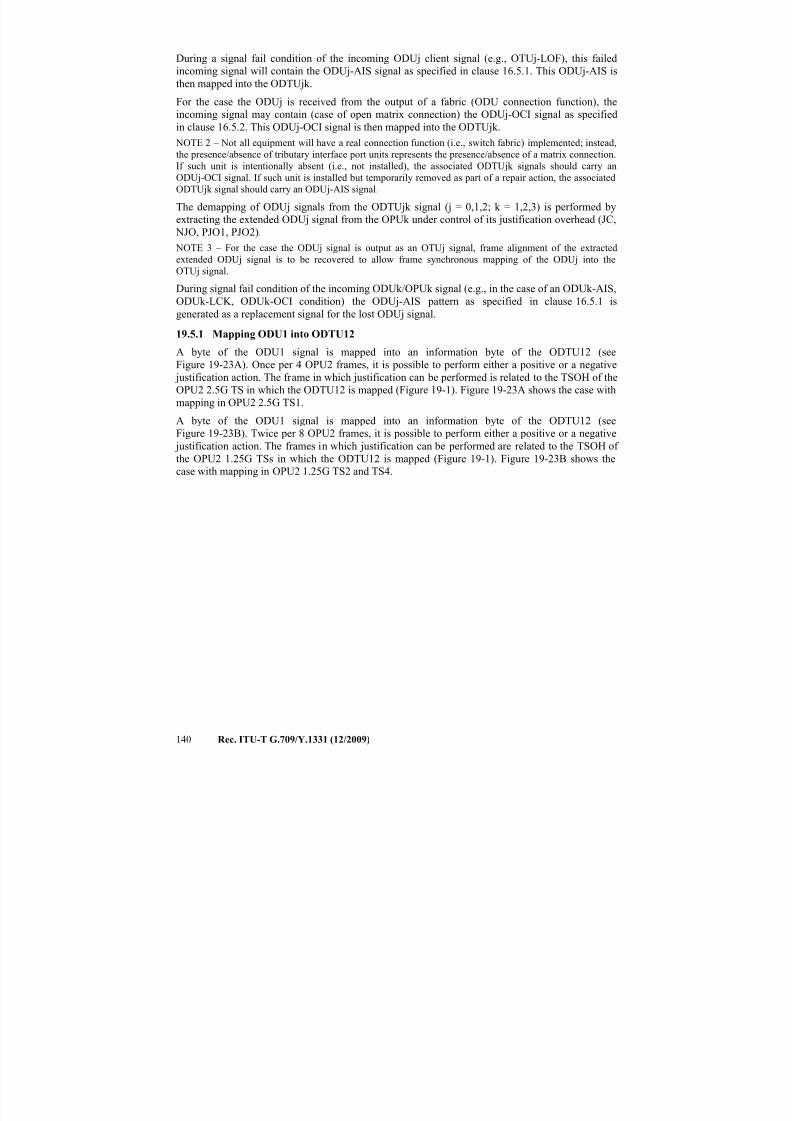
7/16/2019 G-709 ITU_T
http://slidepdf.com/reader/full/g-709-itut 148/218
140 Rec. ITU-T G.709/Y.1331 (12/2009)
During a signal fail condition of the incoming ODUj client signal (e.g., OTUj-LOF), this failed
incoming signal will contain the ODUj-AIS signal as specified in clause 16.5.1. This ODUj-AIS is
then mapped into the ODTUjk.
For the case the ODUj is received from the output of a fabric (ODU connection function), the
incoming signal may contain (case of open matrix connection) the ODUj-OCI signal as specified
in clause 16.5.2. This ODUj-OCI signal is then mapped into the ODTUjk.
NOTE 2 – Not all equipment will have a real connection function (i.e., switch fabric) implemented; instead,
the presence/absence of tributary interface port units represents the presence/absence of a matrix connection.
If such unit is intentionally absent (i.e., not installed), the associated ODTUjk signals should carry an
ODUj-OCI signal. If such unit is installed but temporarily removed as part of a repair action, the associated
ODTUjk signal should carry an ODUj-AIS signal.
The demapping of ODUj signals from the ODTUjk signal (j = 0,1,2; k = 1,2,3) is performed by
extracting the extended ODUj signal from the OPUk under control of its justification overhead (JC,
NJO, PJO1, PJO2).
NOTE 3 – For the case the ODUj signal is output as an OTUj signal, frame alignment of the extracted
extended ODUj signal is to be recovered to allow frame synchronous mapping of the ODUj into the
OTUj signal.
During signal fail condition of the incoming ODUk/OPUk signal (e.g., in the case of an ODUk-AIS,
ODUk-LCK, ODUk-OCI condition) the ODUj-AIS pattern as specified in clause 16.5.1 is
generated as a replacement signal for the lost ODUj signal.
19.5.1 Mapping ODU1 into ODTU12
A byte of the ODU1 signal is mapped into an information byte of the ODTU12 (see
Figure 19-23A). Once per 4 OPU2 frames, it is possible to perform either a positive or a negative
justification action. The frame in which justification can be performed is related to the TSOH of the
OPU2 2.5G TS in which the ODTU12 is mapped (Figure 19-1). Figure 19-23A shows the case with
mapping in OPU2 2.5G TS1.A byte of the ODU1 signal is mapped into an information byte of the ODTU12 (see
Figure 19-23B). Twice per 8 OPU2 frames, it is possible to perform either a positive or a negative
justification action. The frames in which justification can be performed are related to the TSOH of
the OPU2 1.25G TSs in which the ODTU12 is mapped (Figure 19-1). Figure 19-23B shows the
case with mapping in OPU2 1.25G TS2 and TS4.
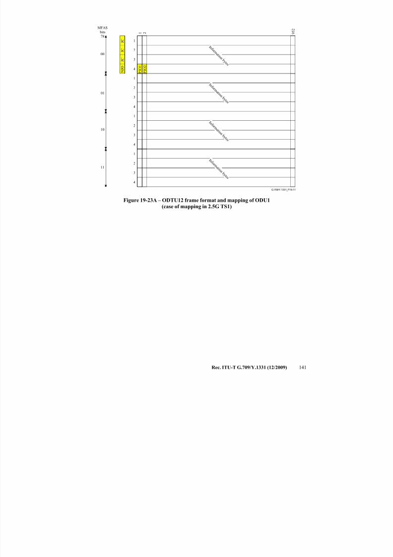
7/16/2019 G-709 ITU_T
http://slidepdf.com/reader/full/g-709-itut 149/218
Rec. ITU-T G.709/Y.1331 (12/2009) 141
G.709/Y.1331_F19-11
I n f o r m a t i o n b y t e s
P J O 1
I n f o r m a t i o
n b y t e s
I n f o r m a t i o n b y t e s
I n f o r m a t i o n b y t e s
00
01
10
11
J C
J C
N J O
J C
P J O 2
MFAS
bits78
1
2
3
4
1
2
3
4
1
2
3
4
1 2 9 5 2
1
2
3
4
Figure 19-23A – ODTU12 frame format and mapping of ODU1(case of mapping in 2.5G TS1)
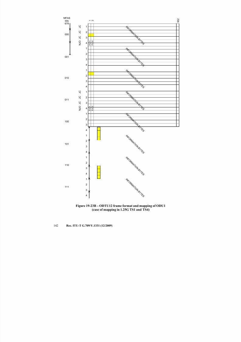
7/16/2019 G-709 ITU_T
http://slidepdf.com/reader/full/g-709-itut 150/218
142 Rec. ITU-T G.709/Y.1331 (12/2009)
1
2
3
4
I N F O R M
A T I O N B Y T E S
P J O 1
1
2
3
4
I N F O R M
A T I O N B Y T E S
1
2
3
4
I N F O R M
A T I O N B Y T E S
1 2 9 5 2
1
2
3
4
I N F O R M
A T I O N B
Y T E S
000
001
010
011
J C
J C
N J O
J C
P J O 2
MFASbits678
1
2
3
4
I N F O R M
A T I O N B Y T E S
P J O 1
1
2
3
4
I N F O R M
A T I O N B Y T E S
1
2
3
4
I N F O R M
A T I O N B Y T E S
1
2
3
4
I N F O R M
A T I O N B Y T E S
100
101
110
111
J C
J C
N J O
J C
P J O 2
Figure 19-23B – ODTU12 frame format and mapping of ODU1
(case of mapping in 1.25G TS1 and TS4)
7/16/2019 G-709 ITU_T
http://slidepdf.com/reader/full/g-709-itut 151/218
Rec. ITU-T G.709/Y.1331 (12/2009) 143
19.5.2 Mapping ODU1 into ODTU13
A byte of the ODU1 signal is mapped into an information byte of the ODTU13 (Figure 19-24A).
Column 119 of the ODTU13 is fixed stuff. An all-0s pattern is inserted in the fixed stuff bytes.
Once per 16 OPU3 frames, it is possible to perform either a positive or a negative justification
action. The frame in which justification can be performed is related to the TSOH of the OPU3 2.5G
TS in which the ODTU13 is mapped (Figure 19-2). Figure 19-24A shows the case with mapping in
OPU3 2.5G TS3.
A byte of the ODU1 signal is mapped into an information byte of the ODTU13 (see
Figure 19-24B). Column 119 of the ODTU13 is fixed stuff. An all-0s pattern is inserted in the fixed
stuff bytes. Twice per 32 OPU3 frames, it is possible to perform either a positive or a negative
justification action. The frames in which justification can be performed are related to the TSOH of
the OPU3 1.25G TSs in which the ODTU13 is mapped (Figure 19-2). Figure 19-24B shows the
case with mapping in OPU3 1.25G TS2 and TS25.
G.709/Y.1331_F19-12
1 2 2 3 8
1
2
3
4
I n f o r m a t i o n b y t e s
1
2
3
4
P J O 1
1
2
3
4
1
2
3
4
J C
J C
N J O
J C
1 1 9
I n f o r m a t i o n b y t e s
I n f o r m a t i o n b y t e s
I n f o r m a t i o n b y t e s
I n f o r m a t i o n b y t e s
I n f o r m a t i o n b y t e s
I n f o r m a t i o n b y t e s
0000
0001
0010
1111
MFAS
bits
5678
F i x e d s t u f f
F i x e d s t u f f
F i x e d s t u f f
I n f o r m a t i o n b y t e s
F i x e d s t u f f
P J O 2
Figure 19-24A – ODTU13 frame format and mapping of ODU1
(case of mapping in 2.5G TS3)
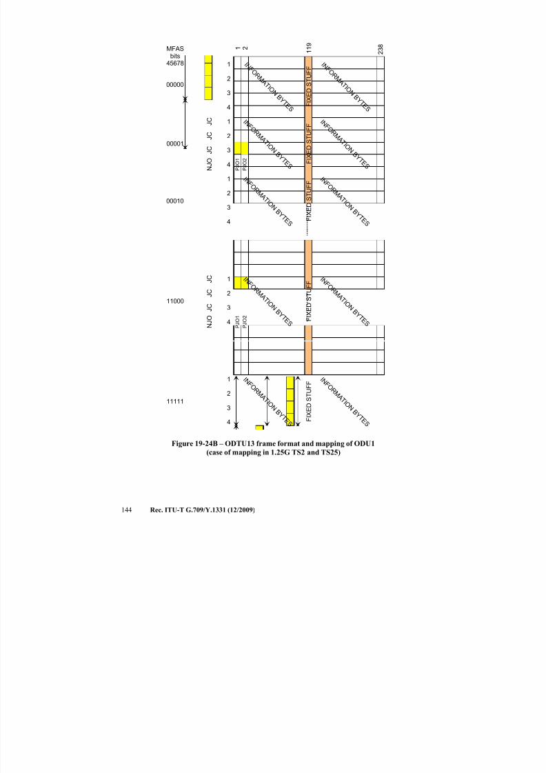
7/16/2019 G-709 ITU_T
http://slidepdf.com/reader/full/g-709-itut 152/218
144 Rec. ITU-T G.709/Y.1331 (12/2009)
1 2 2 3 8
1
2
3
4
I N F O R M A T I O
N B Y T E S
1
2
3
4 P J O 1
1
2
3
4
1
2
3
4
J C
J C
N J O
J C
P J O 2
F I X E D S T U F F
F I X E D S T U F F
F I X E D S T U F
F
1 1 9
I N F O R M
A T I O N B Y T E S
I N F O R M
A T I O N B Y T E S
I N F O R M
A T I O N B Y T E S
I N F O R M
A T I O N B Y T E S
I N F O R M
A T I O N B Y T E S
F I X E D S T U F FI N F O
R M A T I O
N B Y T E S
I N F O R M
A T I O N B Y T E S
00000
00001
00010
11000
MFASbits
45678
1
2
3
4 F I X E D S T U F F
I N F O R M
A T I O N B Y T E S
I N F O R M
A T I O N B Y T E S
11111
P J O 1
J C
J C
N J O
J
C
P J O 2
Figure 19-24B – ODTU13 frame format and mapping of ODU1
(case of mapping in 1.25G TS2 and TS25)

7/16/2019 G-709 ITU_T
http://slidepdf.com/reader/full/g-709-itut 153/218
Rec. ITU-T G.709/Y.1331 (12/2009) 145
19.5.3 Mapping ODU2 into ODTU23
A byte of the ODU2 signal is mapped into an information byte of the ODTU23 (Figure 19-25A).
Four times per sixteen OPU3 frames, it is possible to perform either a positive or a negative
justification action. The four frames in which justification can be performed are related to the
TSOH of the OPU3 2.5G TSs in which the ODTU23 is mapped (Figure 19-2). Figure 19-25A
shows the case with mapping in OPU3 2.5G TS1, TS5, TS9 and TS10.
A byte of the ODU2 signal is mapped into an information byte of the ODTU23 (see
Figure 19-25B). Eight times per 32 OPU3 frames, it is possible to perform either a positive or a
negative justification action. The frames in which justification can be performed are related to the
TSOH of the OPU3 1.25G TSs in which the ODTU23 is mapped (Figure 19-2). Figure 19-25B
shows the case with mapping in OPU3 1.25G TS 1, 2, 5, 9, 10, 25, 26 and 32.
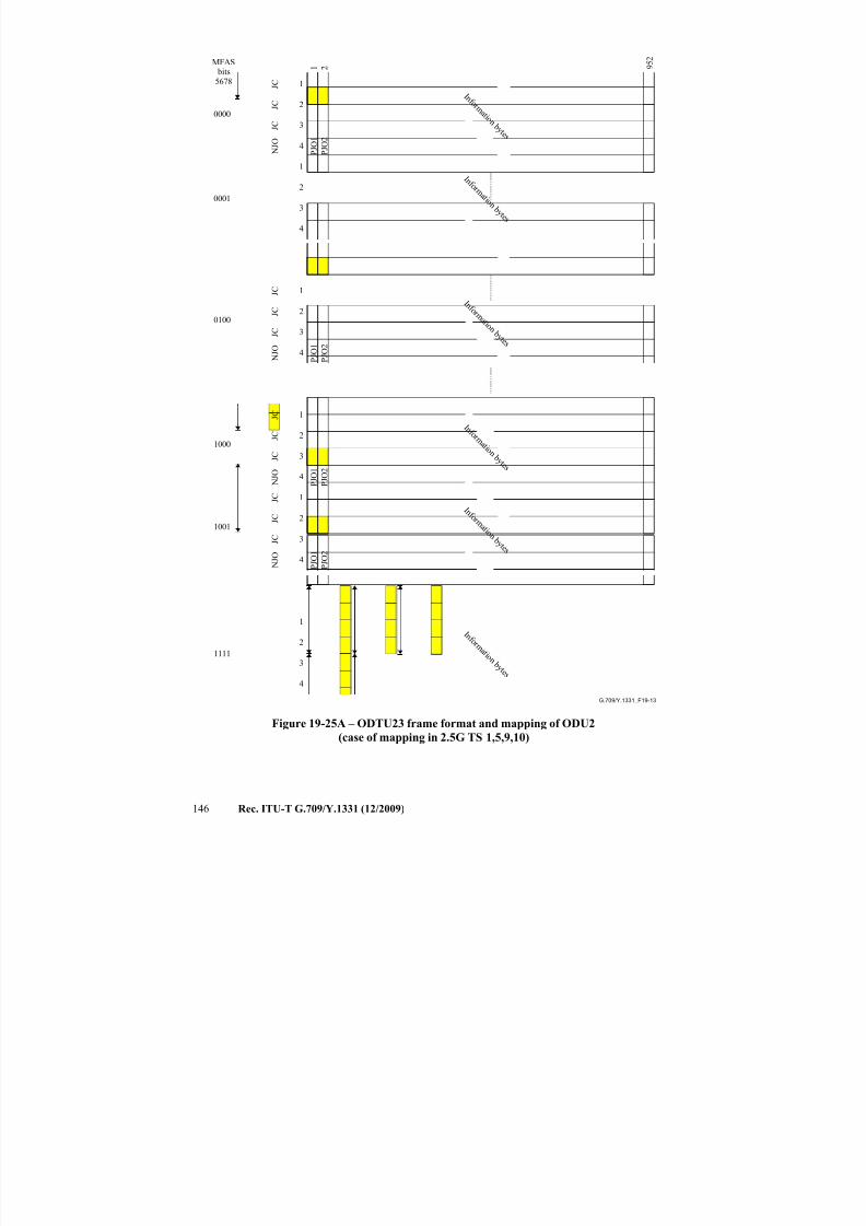
7/16/2019 G-709 ITU_T
http://slidepdf.com/reader/full/g-709-itut 154/218
146 Rec. ITU-T G.709/Y.1331 (12/2009)
G.709/Y.1331_F19-13
I n f o r m a t i o n b y t e s
P J O 1
I n f o r m a t i o n b y t e s
1 2
I n f o r m a t i o n b y t e s
0000
0001
J C
J C
N J O
J C
P J O 2
MFAS bits5678
1
2
3
4
1
2
3
4
1
2
3
4
I n f o r m a t i o n b y t e s
1
2
3
4
0100
1000
1
2
3
4
I n f o r m a t i o n b y t e s
1
2
3
4
I n f o r m a t i o n b y t e s
1001
1111
P J O 1
P J O 1
J C
J C
N J O
J C
J C
J C
N J O
J C
J C
J C
N J O
J C
P J O 2
P J O 1
P J O 2
P J O 2
9 5 2
Figure 19-25A – ODTU23 frame format and mapping of ODU2
(case of mapping in 2.5G TS 1,5,9,10)
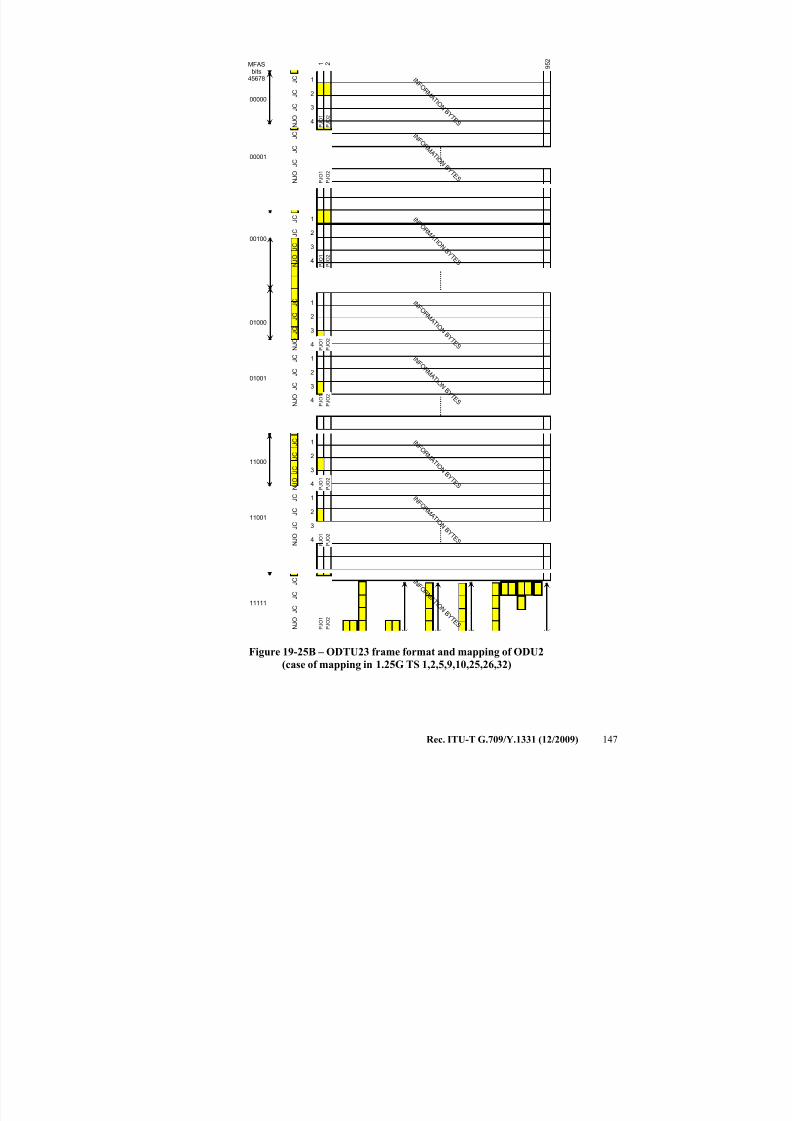
7/16/2019 G-709 ITU_T
http://slidepdf.com/reader/full/g-709-itut 155/218
Rec. ITU-T G.709/Y.1331 (12/2009) 147
1
2
3
4
I N F O R M
A T I O N B Y T E S
P J O 1
1
2
3
4
I N F O R M
A T I O N B Y T E S
1
2
3
4
I N F O R M
A T I O N B Y T E S
1 2 9 5 2
1
2
3
4
I N F O R M
A T I O N B Y T E S
00000
00001
00100
01000
1
2
3
4
I N F O R M
A T I O N B Y T E S
P J O 1
1
2
3
4
I N F O R M
A T I O N B Y T E S
01001
11111
P J O 1
P J O
J C
J C
N J O
J C
J C
J C
N J O
J C
J C
J C
N J O
J C
J C
J C
N J O
J C
P J O 2
P J O 2
P J O 1
P J O 2
P J O 2
MFASbits
45678
P J O 1
J C
J C
N J O
J C
P J O 2
1
2
3
4
I N F O R M
A T I O N B Y T E S
11000
P
J O 1
1
2
3
4
I N F O R M
A T I O N B Y T E
S
11001
P J O
J C
J C
N J O
J C
J C
J C
N
J O
J C
P J O 1
P J O 2
P
J O 2
P J O 1
J C
J C
N J O
J C
P J O 2
Figure 19-25B – ODTU23 frame format and mapping of ODU2
(case of mapping in 1.25G TS 1,2,5,9,10,25,26,32)
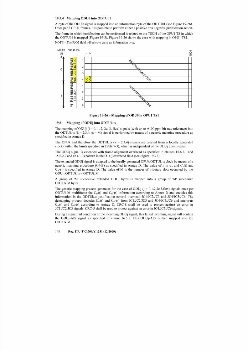
7/16/2019 G-709 ITU_T
http://slidepdf.com/reader/full/g-709-itut 156/218
148 Rec. ITU-T G.709/Y.1331 (12/2009)
19.5.4 Mapping ODU0 into ODTU01
A byte of the ODU0 signal is mapped into an information byte of the ODTU01 (see Figure 19-26).
Once per 2 OPU1 frames, it is possible to perform either a positive or a negative justification action.
The frame in which justification can be performed is related to the TSOH of the OPU1 TS in which
the ODTU01 is mapped (Figure 19-3). Figure 19-26 shows the case with mapping in OPU1 TS1.
NOTE – The PJO2 field will always carry an information byte.
1
2
3
4
I N F O R M A T I O
N B Y T E S
1 2 1 9 0 4
1
2
3
4
I N F O R M A T I O
N B Y T E S
0
1
J C
J C
N J O
J C
MFASbit8
OPU1 OH
P S I R E S R E S R E S
P S I R E S R E S R E S
T S 2 J O H
P J O 2
P J O 1
Figure 19-26 – Mapping of ODU0 in OPU1 TS1
19.6 Mapping of ODUj into ODTUk.ts
The mapping of ODUj (j = 0, 1, 2, 2e, 3, flex) signals (with up to ±100 ppm bit-rate tolerance) intothe ODTUk.ts (k = 2,3,4; ts = M) signal is performed by means of a generic mapping procedure as
specified in Annex D.
The OPUk and therefore the ODTUk.ts (k = 2,3,4) signals are created from a locally generated
clock (within the limits specified in Table 7-3), which is independent of the ODUj client signal.
The ODUj signal is extended with frame alignment overhead as specified in clauses 15.6.2.1 and
15.6.2.2 and an all-0s pattern in the OTUj overhead field (see Figure 19-22).
The extended ODUj signal is adapted to the locally generated OPUk/ODTUk.ts clock by means of a
generic mapping procedure (GMP) as specified in Annex D. The value of n in c n and Cn(t) and
CnD(t) is specified in Annex D. The value of M is the number of tributary slots occupied by theODUj; ODTUk.ts = ODTUk.M.
A group of 'M' successive extended ODUj bytes is mapped into a group of 'M' successive
ODTUk.M bytes.
The generic mapping process generates for the case of ODUj (j = 0,1,2,2e,3,flex) signals once per
ODTUk.M multiframe the Cm(t) and CnD(t) information according to Annex D and encodes this
information in the ODTUk.ts justification control overhead JC1/JC2/JC3 and JC4/JC5/JC6. The
demapping process decodes Cm(t) and CnD(t) from JC1/JC2/JC3 and JC4/JC5/JC6 and interprets
Cm(t) and CnD(t) according to Annex D. CRC-8 shall be used to protect against an error in
JC1,JC2,JC3 signals. CRC-5 shall be used to protect against an error in JC4,JC5,JC6 signals.
During a signal fail condition of the incoming ODUj signal, this failed incoming signal will containthe ODUj-AIS signal as specified in clause 16.5.1. This ODUj-AIS is then mapped into the
ODTUk.M.
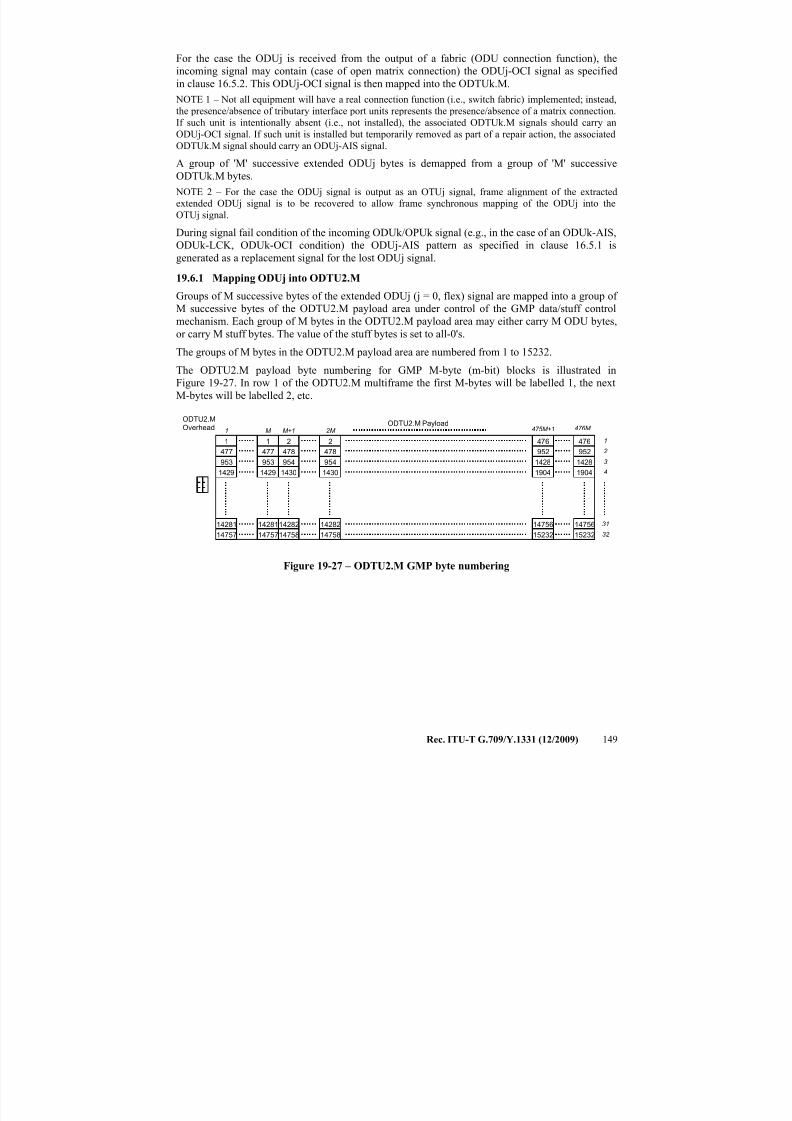
7/16/2019 G-709 ITU_T
http://slidepdf.com/reader/full/g-709-itut 157/218
Rec. ITU-T G.709/Y.1331 (12/2009) 149
For the case the ODUj is received from the output of a fabric (ODU connection function), the
incoming signal may contain (case of open matrix connection) the ODUj-OCI signal as specified
in clause 16.5.2. This ODUj-OCI signal is then mapped into the ODTUk.M.
NOTE 1 – Not all equipment will have a real connection function (i.e., switch fabric) implemented; instead,
the presence/absence of tributary interface port units represents the presence/absence of a matrix connection.
If such unit is intentionally absent (i.e., not installed), the associated ODTUk.M signals should carry an
ODUj-OCI signal. If such unit is installed but temporarily removed as part of a repair action, the associatedODTUk.M signal should carry an ODUj-AIS signal.
A group of 'M' successive extended ODUj bytes is demapped from a group of 'M' successive
ODTUk.M bytes.
NOTE 2 – For the case the ODUj signal is output as an OTUj signal, frame alignment of the extracted
extended ODUj signal is to be recovered to allow frame synchronous mapping of the ODUj into the
OTUj signal.
During signal fail condition of the incoming ODUk/OPUk signal (e.g., in the case of an ODUk-AIS,
ODUk-LCK, ODUk-OCI condition) the ODUj-AIS pattern as specified in clause 16.5.1 is
generated as a replacement signal for the lost ODUj signal.
19.6.1 Mapping ODUj into ODTU2.M
Groups of M successive bytes of the extended ODUj (j = 0, flex) signal are mapped into a group of
M successive bytes of the ODTU2.M payload area under control of the GMP data/stuff control
mechanism. Each group of M bytes in the ODTU2.M payload area may either carry M ODU bytes,
or carry M stuff bytes. The value of the stuff bytes is set to all-0's.
The groups of M bytes in the ODTU2.M payload area are numbered from 1 to 15232.
The ODTU2.M payload byte numbering for GMP M-byte (m-bit) blocks is illustrated in
Figure 19-27. In row 1 of the ODTU2.M multiframe the first M-bytes will be labelled 1, the next
M-bytes will be labelled 2, etc.
1 M M+1 475M+1 476M ODTU2.M Payload
ODTU2.MOverhead
1 1 2 2
477
953
1429
14281
14757
476 476
952
1428
1904
14756
15232
2M
952
1428
1904
14756
15232
477
953
1429
14281
14757
478
954
1430
14282
14758
478
954
1430
14282
14758
1
2
3
4
31
32
Figure 19-27 – ODTU2.M GMP byte numbering
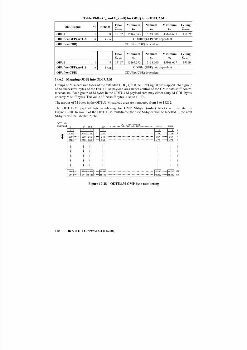
7/16/2019 G-709 ITU_T
http://slidepdf.com/reader/full/g-709-itut 158/218
150 Rec. ITU-T G.709/Y.1331 (12/2009)
Table 19-8 – Cm and Cn (n=8) for ODUj into ODTU2.M
ODUj signal M m=8×MFloor
Cm,min
Minimum
cm
Nominal
cm
Maximum
cm
Ceiling
Cm,max
ODU0 1 8 15167 15167.393 15168.000 15168.607 15169
ODUflex(GFP), n=1..8 n 8 × n ODUflex(GFP) rate dependent
ODUflex(CBR) ODUflex(CBR) dependent
Floor
C8,min
Minimum
c8
Nominal
c8
Maximum
c8
Ceiling
C8,max
ODU0 1 8 15167 15167.393 15168.000 15168.607 15169
ODUflex(GFP), n=1..8 n 8 × n ODUflex(GFP) rate dependent
ODUflex(CBR) ODUflex(CBR) dependent
19.6.2 Mapping ODUj into ODTU3.M
Groups of M successive bytes of the extended ODUj (j = 0, 2e, flex) signal are mapped into a groupof M successive bytes of the ODTU3.M payload area under control of the GMP data/stuff control
mechanism. Each group of M bytes in the ODTU3.M payload area may either carry M ODU bytes,
or carry M stuff bytes. The value of the stuff bytes is set to all-0's.
The groups of M bytes in the ODTU3.M payload area are numbered from 1 to 15232.
The ODTU3.M payload byte numbering for GMP M-byte (m-bit) blocks is illustrated in
Figure 19-28. In row 1 of the ODTU3.M multiframe the first M-bytes will be labelled 1, the next
M-bytes will be labelled 2, etc.
1 M M+1118M+1 119M
ODTU3.M PayloadODTU3.MOverhead
1 1 2 2
120
239
358
14995
15114
119 119
238
357
476
15113
15232
2M
238
357
476
15113
15232
120
239
358
14995
15114
121
240
359
14996
15115
121
240
359
14996
15115
1
2
3
4
127
128
Figure 19-28 – ODTU3.M GMP byte numbering
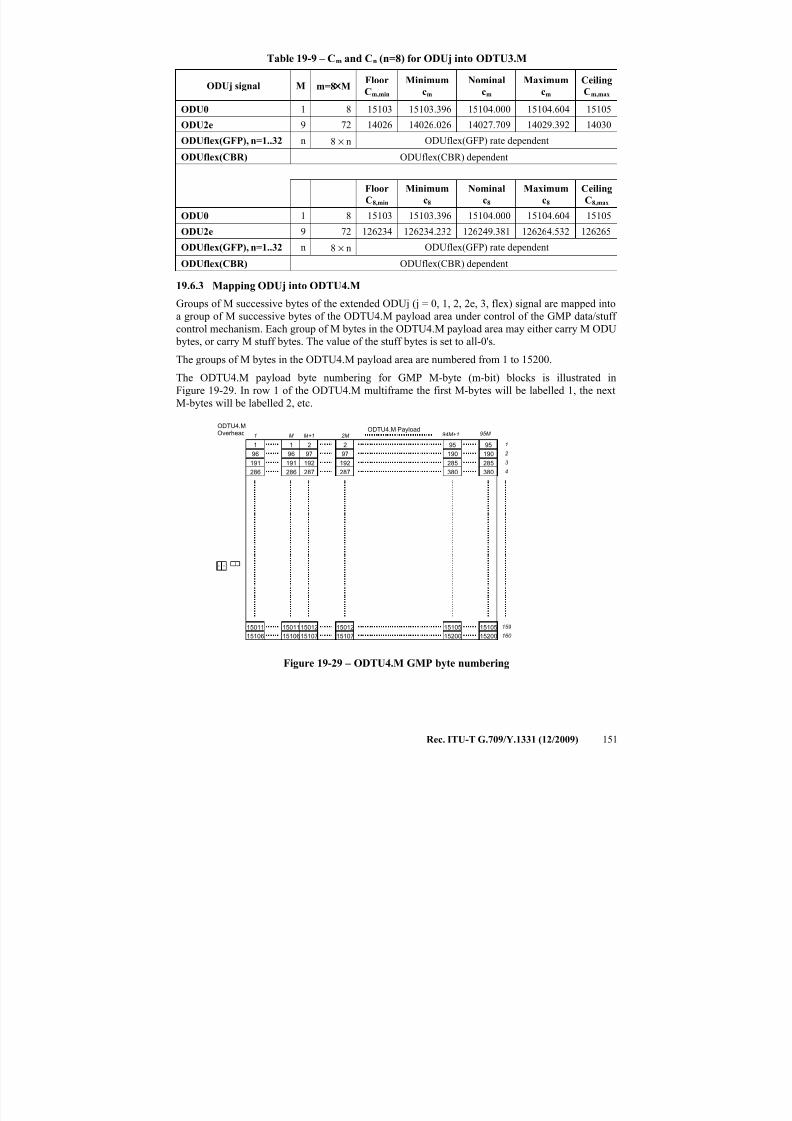
7/16/2019 G-709 ITU_T
http://slidepdf.com/reader/full/g-709-itut 159/218
Rec. ITU-T G.709/Y.1331 (12/2009) 151
Table 19-9 – Cm and Cn (n=8) for ODUj into ODTU3.M
ODUj signal M m=8×MFloor
Cm,min
Minimum
cm
Nominal
cm
Maximum
cm
Ceiling
Cm,max
ODU0 1 8 15103 15103.396 15104.000 15104.604 15105
ODU2e 9 72 14026 14026.026 14027.709 14029.392 14030
ODUflex(GFP), n=1..32 n 8 × n ODUflex(GFP) rate dependent
ODUflex(CBR) ODUflex(CBR) dependent
Floor
C8,min
Minimum
c8
Nominal
c8
Maximum
c8
Ceiling
C8,max
ODU0 1 8 15103 15103.396 15104.000 15104.604 15105
ODU2e 9 72 126234 126234.232 126249.381 126264.532 126265
ODUflex(GFP), n=1..32 n 8 × n ODUflex(GFP) rate dependent
ODUflex(CBR) ODUflex(CBR) dependent
19.6.3 Mapping ODUj into ODTU4.M
Groups of M successive bytes of the extended ODUj (j = 0, 1, 2, 2e, 3, flex) signal are mapped into
a group of M successive bytes of the ODTU4.M payload area under control of the GMP data/stuff
control mechanism. Each group of M bytes in the ODTU4.M payload area may either carry M ODU
bytes, or carry M stuff bytes. The value of the stuff bytes is set to all-0's.
The groups of M bytes in the ODTU4.M payload area are numbered from 1 to 15200.
The ODTU4.M payload byte numbering for GMP M-byte (m-bit) blocks is illustrated in
Figure 19-29. In row 1 of the ODTU4.M multiframe the first M-bytes will be labelled 1, the next
M-bytes will be labelled 2, etc.
1 M M+1 94M+1 95M ODTU4.M Payload
ODTU4.MOverhead
1 1 2 2
96
191
286
15011
15106
95 95
190
285
380
15105
15200
2M
190
285
380
15105
15200
96
191
286
15011
15106
97
192
287
15012
15107
97
192
287
15012
15107
1
2
3
4
159
160
Figure 19-29 – ODTU4.M GMP byte numbering
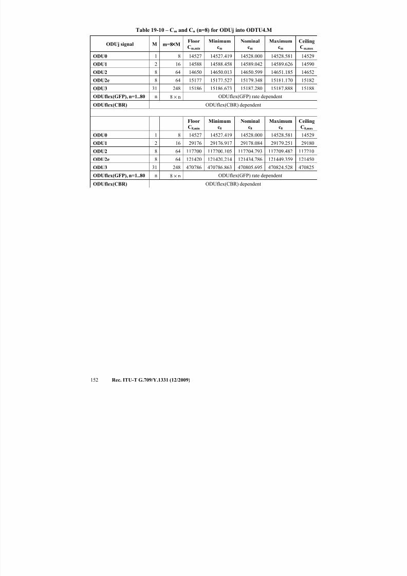
7/16/2019 G-709 ITU_T
http://slidepdf.com/reader/full/g-709-itut 160/218
152 Rec. ITU-T G.709/Y.1331 (12/2009)
Table 19-10 – Cm and Cn (n=8) for ODUj into ODTU4.M
ODUj signal M m=8×MFloor
Cm,min
Minimum
cm
Nominal
cm
Maximum
cm
Ceiling
Cm,max
ODU0 1 8 14527 14527.419 14528.000 14528.581 14529
ODU1 2 16 14588 14588.458 14589.042 14589.626 14590
ODU2 8 64 14650 14650.013 14650.599 14651.185 14652
ODU2e 8 64 15177 15177.527 15179.348 15181.170 15182
ODU3 31 248 15186 15186.673 15187.280 15187.888 15188
ODUflex(GFP), n=1..80 n 8 × n ODUflex(GFP) rate dependent
ODUflex(CBR) ODUflex(CBR) dependent
Floor
C8,min
Minimum
c8
Nominal
c8
Maximum
c8
Ceiling
C8,max
ODU0 1 8 14527 14527.419 14528.000 14528.581 14529
ODU1 2 16 29176 29176.917 29178.084 29179.251 29180
ODU2 8 64 117200 117200.105 117204.793 117209.482 117210
ODU2e 8 64 121420 121420.214 121434.786 121449.359 121450
ODU3 31 248 470786 470786.863 470805.695 470824.528 470825
ODUflex(GFP), n=1..80 n 8 × n ODUflex(GFP) rate dependent
ODUflex(CBR) ODUflex(CBR) dependent
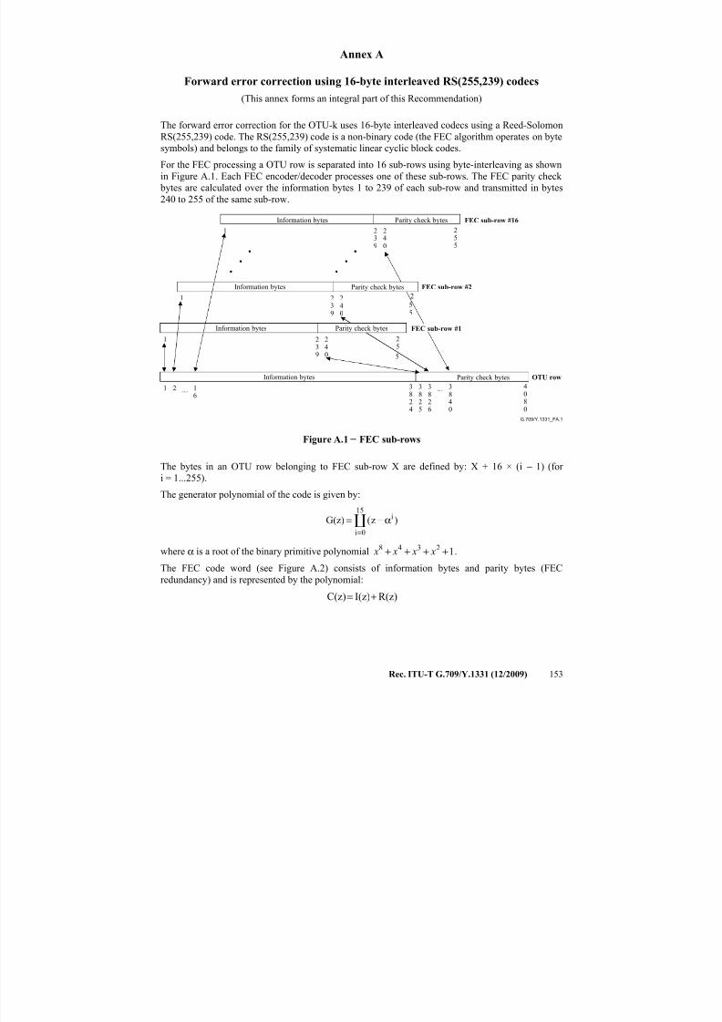
7/16/2019 G-709 ITU_T
http://slidepdf.com/reader/full/g-709-itut 161/218
Rec. ITU-T G.709/Y.1331 (12/2009) 153
Annex A
Forward error correction using 16-byte interleaved RS(255,239) codecs
(This annex forms an integral part of this Recommendation)
The forward error correction for the OTU-k uses 16-byte interleaved codecs using a Reed-SolomonRS(255,239) code. The RS(255,239) code is a non-binary code (the FEC algorithm operates on byte
symbols) and belongs to the family of systematic linear cyclic block codes.
For the FEC processing a OTU row is separated into 16 sub-rows using byte-interleaving as shown
in Figure A.1. Each FEC encoder/decoder processes one of these sub-rows. The FEC parity check
bytes are calculated over the information bytes 1 to 239 of each sub-row and transmitted in bytes
240 to 255 of the same sub-row.
G.709/Y.1331_FA.1
Information bytes
Information bytes OTU row
Information bytes
Information bytes Parity check bytes FEC sub-row #16
Parity check bytes FEC sub-row #2
Parity check bytes FEC sub-row #1
Parity check bytes
...1 2 16
3825
3826
3840
3824
4080
239
1 240
239
1 240
23
9
1 24
0
...
25
5
255
25
5
Figure A.1 − FEC sub-rows
The bytes in an OTU row belonging to FEC sub-row X are defined by: X + 16 × (i − 1) (for
i = 1...255).
The generator polynomial of the code is given by:
15
0i
i )z(G(z)
=
α−=
where α is a root of the binary primitive polynomial 12348 ++++ x x x x .
The FEC code word (see Figure A.2) consists of information bytes and parity bytes (FEC
redundancy) and is represented by the polynomial:
R(z)I(z)C(z) +=
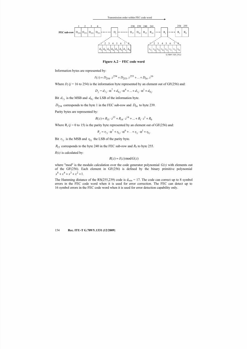
7/16/2019 G-709 ITU_T
http://slidepdf.com/reader/full/g-709-itut 162/218
154 Rec. ITU-T G.709/Y.1331 (12/2009)
G.709/Y.1331_FA.2
FEC sub-row
Transmission order within FEC code word
D254
1 2 3 4 238 239 240 254 255
1 2 3 4 5 6 7 8 1 2 3 4 5 6 7 8
D253 D252 D251 D j D17 D16 R 15 R j R 1 R 0
d7j d6j d5j d4j d3j d2j d1j d0j r 7j r 6j r 5j r 4j r 3j r 2j r 1j r 0j
241
R 14
Figure A.2 − FEC code word
Information bytes are represented by:
1616
253253
254254 ......)( z D z D z D z I +++=
Where D j ( j = 16 to 254) is the information byte represented by an element out of GF(256) and:
j j j j j d d d d D 01
16
67
7 ... +α⋅++α⋅+α⋅=
Bit jd 7 is the MSB and jd 0 the LSB of the information byte.
254 D corresponds to the byte 1 in the FEC sub-row and 16 D to byte 239.
Parity bytes are represented by:
01
114
1415
15 ...)( R z R z R z R z R +⋅++⋅+⋅=
Where R j ( j = 0 to 15) is the parity byte represented by an element out of GF(256) and:
j j j j j r r r r R 01
16
67
7 ... +α⋅++α⋅+α⋅=
Bit jr 7 is the MSB and jr 0 the LSB of the parity byte.
15 R corresponds to the byte 240 in the FEC sub-row and R0 to byte 255.
R(z) is calculated by:
( ) ( ) mod ( ) R z I z G z =
where "mod" is the modulo calculation over the code generator polynomial G(z) with elements out
of the GF(256). Each element in GF(256) is defined by the binary primitive polynomial12348 ++++ x x x x .
The Hamming distance of the RS(255,239) code is dmin = 17. The code can correct up to 8 symbolerrors in the FEC code word when it is used for error correction. The FEC can detect up to
16 symbol errors in the FEC code word when it is used for error detection capability only.
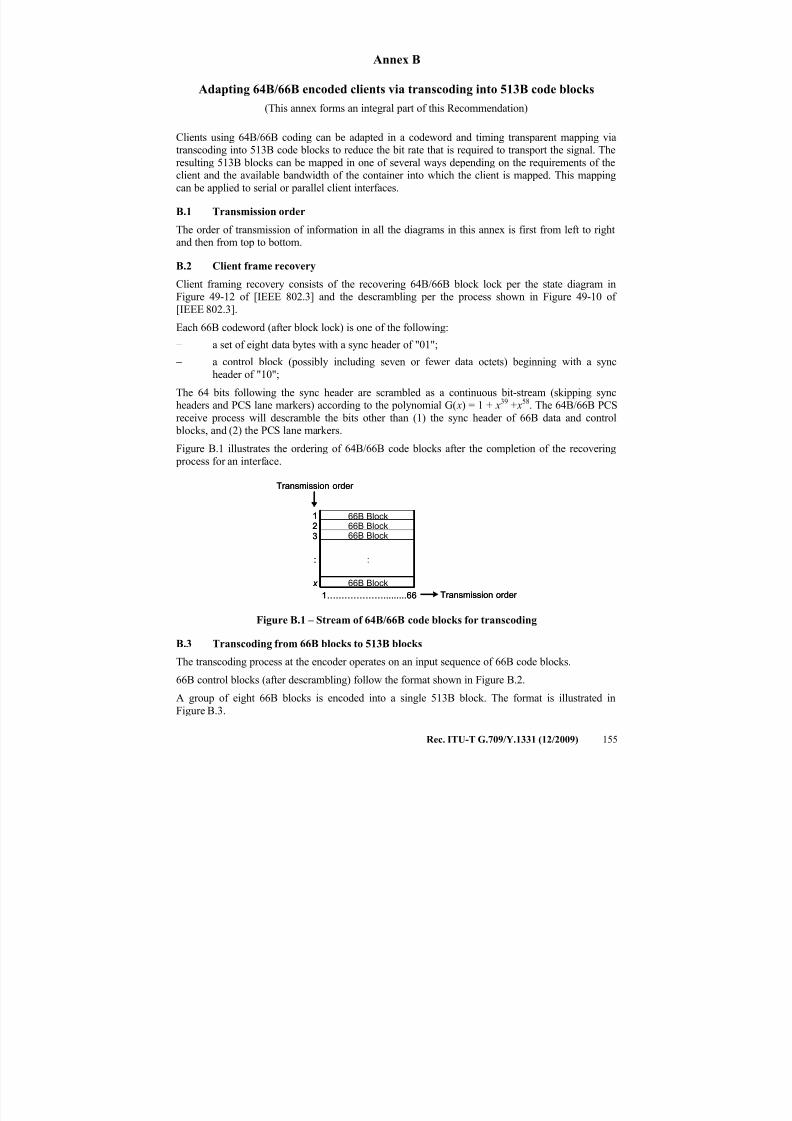
7/16/2019 G-709 ITU_T
http://slidepdf.com/reader/full/g-709-itut 163/218
Rec. ITU-T G.709/Y.1331 (12/2009) 155
Annex B
Adapting 64B/66B encoded clients via transcoding into 513B code blocks
(This annex forms an integral part of this Recommendation)
Clients using 64B/66B coding can be adapted in a codeword and timing transparent mapping viatranscoding into 513B code blocks to reduce the bit rate that is required to transport the signal. The
resulting 513B blocks can be mapped in one of several ways depending on the requirements of theclient and the available bandwidth of the container into which the client is mapped. This mapping
can be applied to serial or parallel client interfaces.
B.1 Transmission order
The order of transmission of information in all the diagrams in this annex is first from left to rightand then from top to bottom.
B.2 Client frame recovery
Client framing recovery consists of the recovering 64B/66B block lock per the state diagram inFigure 49-12 of [IEEE 802.3] and the descrambling per the process shown in Figure 49-10 of
[IEEE 802.3].
Each 66B codeword (after block lock) is one of the following:
− a set of eight data bytes with a sync header of "01";
− a control block (possibly including seven or fewer data octets) beginning with a sync
header of "10";
The 64 bits following the sync header are scrambled as a continuous bit-stream (skipping sync
headers and PCS lane markers) according to the polynomial G( x) = 1 + x39
+ x58
. The 64B/66B PCSreceive process will descramble the bits other than (1) the sync header of 66B data and control blocks, and (2) the PCS lane markers.
Figure B.1 illustrates the ordering of 64B/66B code blocks after the completion of the recovering
process for an interface.
Figure B.1 – Stream of 64B/66B code blocks for transcoding
B.3 Transcoding from 66B blocks to 513B blocks
The transcoding process at the encoder operates on an input sequence of 66B code blocks.
66B control blocks (after descrambling) follow the format shown in Figure B.2.
A group of eight 66B blocks is encoded into a single 513B block. The format is illustrated in
Figure B.3.
1….…………….........66
12
x
3
Transmission order
Transmission order
66B Block66B Block66B Block
:
66B Block
:
1….…………….........66
12
x
3
Transmission order
Transmission order
66B Block66B Block66B Block
:
66B Block
66B Block66B Block66B Block66B Block66B Block
:
66B Block
:
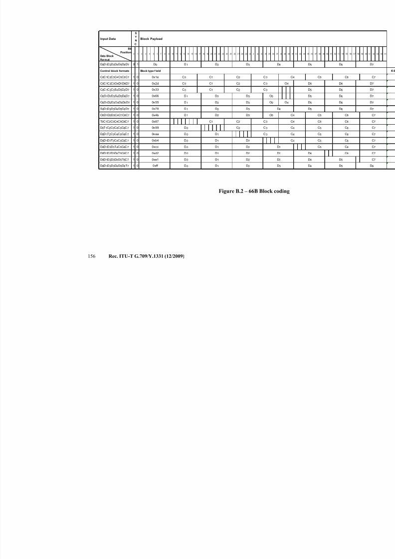
7/16/2019 G-709 ITU_T
http://slidepdf.com/reader/full/g-709-itut 164/218
156 Rec. ITU-T G.709/Y.1331 (12/2009)
Figure B.2 – 66B Block coding
Bit
Position
Data Block
Format
0 1
1 0
1 0
1 0
1 0
1 0
1 0
1 0
1 0
1 0
1 0
1 0
1 0
1 0
1 0
1 0
C5
O0 O4
D4 D5
O0 C4
O0D1D2D3O4D5D6D7 0x55 D1 D2 D3 D5
O0D1 D2 D3
D5
C0 C1 C2 C3
D5
O4C0 C1 C2 C30x2d
0x66
C0C1C2C3O4D5D6D7
C0C1C2C3S4D5D6D7 0x33
O0D1D2D3S4D5D6D7
D0D1D2D3D4T5C6C7
D0D1D2D3D4D5T6C7
D0D1D2D3D4D5D6T7
0xd2
0xe1
0xff D2 D3 D4
D0D1D2T3C4C5C6C7
D0D1D2D3T4C5C6C7
D0 D1
0xb4
0xcc
D4D2
D4
D0 D1
D0 D1 D2 D3
D3
C5
C5D0 D1 D2 D3
D0 D1 D2 C4
D0D1T2C3C4C5C6C7 D0 D1 C30xaa C4 C5
0x87
D0T1C2C3C4C5C6C7 C2 C3D00x99 C4 C5
T0C1C2C3C4C5C6C7 C1 C2 C3 C4 C5
5147 48 49 5043 44 45 4639 40 41 4235 36 37 38
D1 D2 D3O0D1D2D3C4C5C6C7 0x4b
16 17 18 19 2012 13 14 15
D3
D5
C3 C4 C5
S0D1D2D3D4D5D6D7 D1 D2
Block type f ield
C0 C1 C20x1e
0x78
C0C1C2C3C4C5C6C7
22 23 28 29 30 31 32 33 348 9 10 11 24 25 26 2721
Control block formats
D0
0 1 2 3 4 5 6
Input Data
D0D1D2D3D4D5D6D7
S
Y
N
C
Block Payload
D1
7
D2 D3 D4 D5
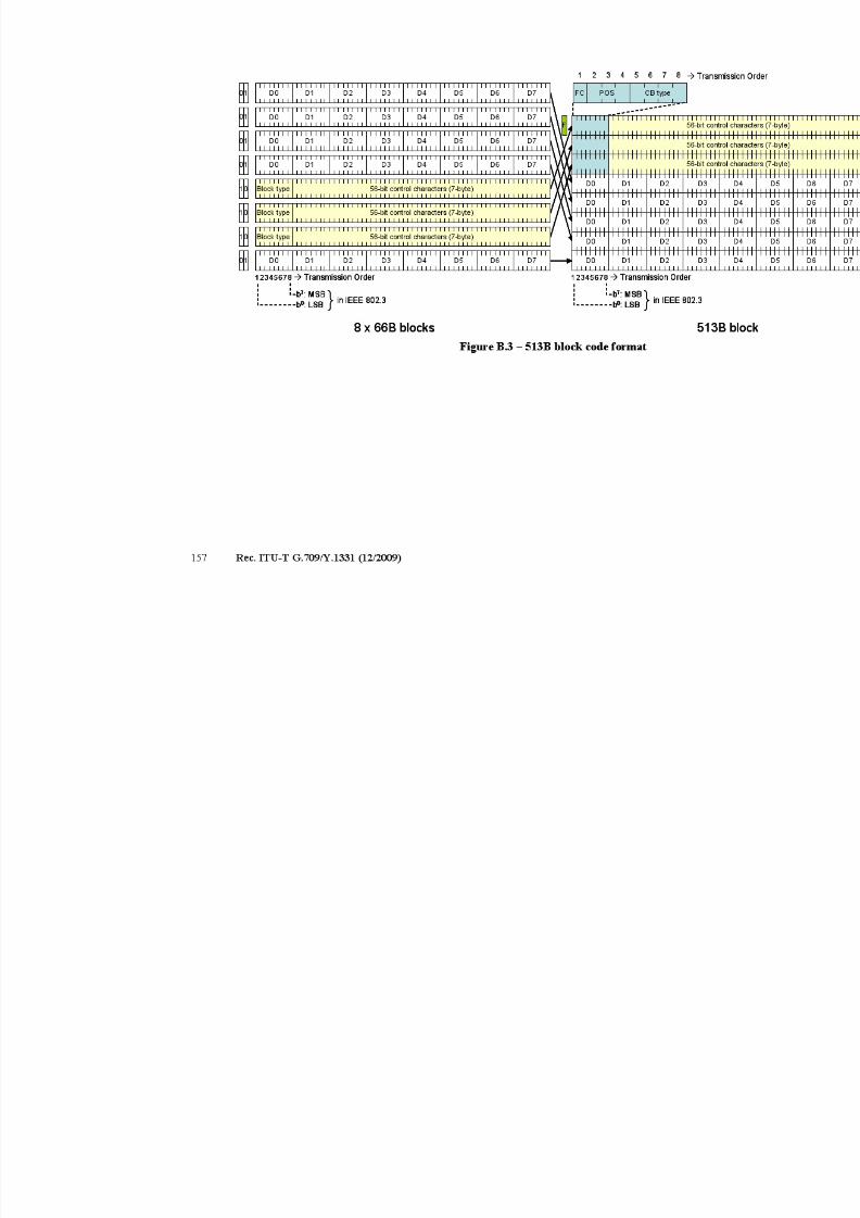
7/16/2019 G-709 ITU_T
http://slidepdf.com/reader/full/g-709-itut 165/218
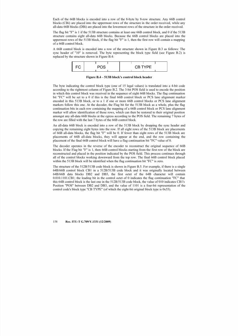
7/16/2019 G-709 ITU_T
http://slidepdf.com/reader/full/g-709-itut 166/218
158 Rec. ITU-T G.709/Y.1331 (12/2009)
Each of the 66B blocks is encoded into a row of the 8-byte by 8-row structure. Any 66B control blocks (CBi) are placed into the uppermost rows of the structure in the order received, while any
all-data 66B blocks (DBi) are placed into the lowermost rows of the structure in the order received.
The flag bit "F" is 1 if the 513B structure contains at least one 66B control block, and 0 if the 513B
structure contains eight all-data 66B blocks. Because the 66B control blocks are placed into the
uppermost rows of the 513B block, if the flag bit "F" is 1, then the first row will contain a mappingof a 66B control block.
A 66B control block is encoded into a row of the structure shown in Figure B.3 as follows: Thesync header of "10" is removed. The byte representing the block type field (see Figure B.2) is
replaced by the structure shown in Figure B.4:
Figure B.4 – 513B block's control block header
The byte indicating the control block type (one of 15 legal values) is translated into a 4-bit code
according to the rightmost column of Figure B.2. The 3-bit POS field is used to encode the positionin which this control block was received in the sequence of eight 66B blocks. The flag continuation
bit "FC" will be set to a 0 if this is the final 66B control block or PCS lane alignment marker
encoded in this 513B block, or to a 1 if one or more 66B control blocks or PCS lane alignmentmarkers follow this one. At the decoder, the Flag bit for the 513B block as a whole, plus the flag
continuation bits in each row containing the mapping of a 66B control block or PCS lane alignmentmarker will allow identification of those rows, which can then be restored to their original position
amongst any all-data 66B blocks at the egress according to the POS field. The remaining 7 bytes of the row are filled with the last 7 bytes of the 66B control block.
An all-data 66B block is encoded into a row of the 513B block by dropping the sync header and
copying the remaining eight bytes into the row. If all eight rows of the 513B block are placementsof 66B all-data blocks, the flag bit "F" will be 0. If fewer than eight rows of the 513B block are
placements of 66B all-data blocks, they will appear at the end, and the row containing the
placement of the final 66B control block will have a flag continuation bit "FC" value of 0.
The decoder operates in the reverse of the encoder to reconstruct the original sequence of 66B blocks. If the Flag bit "F" is 1, then 66B control blocks starting from the first row of the block are
reconstructed and placed in the position indicated by the POS field. This process continues throughall of the control blocks working downward from the top row. The final 66B control block placed
within the 513B block will be identified when the flag continuation bit "FC" is zero.
The structure of the 512B/513B code block is shown in Figure B.5. For example, if there is a single64B/66B control block CB1 in a 512B/513B code block and it was originally located between
64B/66B data blocks DB2 and DB3, the first octet of the 64B character will contain
0.010.1101.CB1; the leading bit in the control octet of 0 indicates the flag continuation "FC" thatthis 64B control block is the last one in the 512B/513B code block, the value of 010 indicates CB1's
Position "POS" between DB2 and DB3, and the value of 1101 is a four-bit representation of thecontrol code's block type "CB TYPE" (of which the eight-bit original block type is 0x55).
POS CB TYPEFC
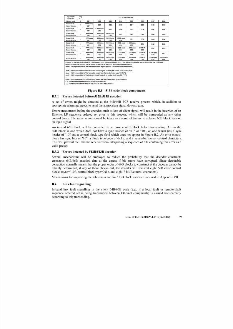
7/16/2019 G-709 ITU_T
http://slidepdf.com/reader/full/g-709-itut 167/218
Rec. ITU-T G.709/Y.1331 (12/2009) 159
0 HHH hhhh
CB8
1 GGG gggg
CB7
1 FFF ffff
CB6
1 EEE eeee
CB5
1 DDD dddd
CB4
1 CCC cccc
CB3
1 BBB bbbb
CB2
1 AAA aaaa
CB118 control block
1 DDD dddd
CB4
1 DDD dddd
CB4
1 DDD dddd
CB4
0 DDD dddd
CB4
DB1
DB2
DB3
DB4
1 CCC cccc
CB3
1 CCC cccc
CB3
1 CCC cccc
CB3
1 CCC cccc
CB3
0 CCC cccc
CB3
DB1
DB2
DB3
1 BBB bbbb
CB2
1 BBB bbbb
CB2
1 BBB bbbb
CB2
1 BBB bbbb
CB2
1 BBB bbbb
CB2
0 BBB bbbb
CB2
DB1
DB2
1 AAA aaaa
CB1
1 AAA aaaa
CB1
1 AAA aaaa
CB1
1 AAA aaaa
CB1
1 AAA aaaa
CB1
1 AAA aaaa
CB1
0 AAA aaaa
CB1
DB1
512-bit (64-Octet) field
DB4DB3DB2DB11
4 data block,
4 control block
DB5DB4DB3DB215 data block,
3 control block
DB6DB5DB4DB316 data block,
2 control block
DB7DB6DB5DB417 data block,
1 control block
-Leading bit in a 66B control block FC = 1 if there are more 66Bcontrol block and = 0 if this payload contains the last controlblock in that 513B block
-AAA = 3- bit representation of the 1 st control code’s original position (1st control code locator: POS)
-BBB = 3-bit representation of the 2 nd control code’s original position (2nd control code locator: POS)
….
-HHH = 3-bit representation of the 8 th control code’s original position (8th control code locator: POS)
-aaaa = 4-bit representation of the 1 st control code’s type (1 st control block type: CB TYPE)
-bbbb = 4-bit representation of the 2 nd control code’s type (2 nd control block type: CB TYPE)
….
-hhhh = 4-bit representation of the 8 th control code’s type (8 th control block type: CB TYPE)-CBi = 56-bit representation of the i th control code characters
-DBi = 64-bit representation of the i th data value in order of transmission
DB10 GGG gggg
CB7
1 FFF ffff
CB6
1 EEE eeee
CB51
1 data block,
7 control block
DB2DB10 FFF ffff
CB6
1 EEE eeee
CB51
2 data block,
6 control block
DB3DB2DB10 EEE eeee
CB51
3 data block,
5 control block
DB8DB7DB6DB50 All data block
Flag
bit
Input client
characters
Figure B.5 – 513B code block components
B.3.1 Errors detected before 512B/513B encoder
A set of errors might be detected at the 64B/66B PCS receive process which, in addition to
appropriate alarming, needs to send the appropriate signal downstream.
Errors encountered before the encoder, such as loss of client signal, will result in the insertion of anEthernet LF sequence ordered set prior to this process, which will be transcoded as any other
control block. The same action should be taken as a result of failure to achieve 66B block lock onan input signal
An invalid 66B block will be converted to an error control block before transcoding. An invalid
66B block is one which does not have a sync header of "01" or "10", or one which has a syncheader of "10" and a control block type field which does not appear in Figure B.2. An error control
block has sync bits of "10", a block type code of 0x1E, and 8 seven-bit/E/error control characters.
This will prevent the Ethernet receiver from interpreting a sequence of bits containing this error as avalid packet.
B.3.2 Errors detected by 512B/513B decoder
Several mechanisms will be employed to reduce the probability that the decoder constructs
erroneous 64B/66B encoded data at the egress if bit errors have corrupted. Since detectablecorruption normally means that the proper order of 66B blocks to construct at the decoder cannot be
reliably determined, if any of these checks fail, the decoder will transmit eight 66B error control blocks (sync="10", control block type=0x1e, and eight 7-bit/E/control characters).
Mechanisms for improving the robustness and for 513B block lock are discussed in Appendix VII.
B.4 Link fault signalling
In-band link fault signalling in the client 64B/66B code (e.g., if a local fault or remote fault
sequence ordered set is being transmitted between Ethernet equipments) is carried transparentlyaccording to this transcoding.
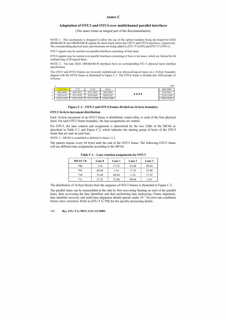
7/16/2019 G-709 ITU_T
http://slidepdf.com/reader/full/g-709-itut 168/218
160 Rec. ITU-T G.709/Y.1331 (12/2009)
Annex C
Adaptation of OTU3 and OTU4 over multichannel parallel interfaces
(This annex forms an integral part of this Recommendation)
NOTE 1 – This mechanism is designed to allow the use of the optical modules being developed for IEEE40GBASE-R and 100GBASE-R signals for short-reach client-side OTU3 and OTU4 interfaces, respectively.
The corresponding physical layer specifications are being added to [ITU-T G.695] and [ITU-T G.959.1].
OTU3 signals may be carried over parallel interfaces consisting of four lanes.
OTU4 signals may be carried over parallel interfaces consisting of four or ten lanes, which are formed by bit
multiplexing of 20 logical lanes.
NOTE 2 – Ten lane IEEE 100GBASE-R interfaces have no corresponding ITU-T physical layer interface
specification.
The OTU3 and OTU4 frames are inversely multiplexed over physical/logical lanes on a 16-byte boundary
aligned with the OTUk frame as illustrated in Figure C.1. The OTUk frame is divided into 1020 groups of
16-bytes.
12241:12256
9161:9176
4081:4096
1:16 (FAS)
4
3
2
1
12257:12272
9177:9192
4097:5012
17:32
12273:12288
9193:9208
5013:5028
33:48
12289:13304
9209:9224
5029:5044
49:64
16305:16320
12225:12240
9145:9160
4065:4080
1 4080
Figure C.1 – OTU3 and OTU4 frames divided on 16-byte boundary
OTU3 16-byte increment distribution
Each 16-byte increment of an OTU3 frame is distributed, round robin, to each of the four physicallanes. On each OTU3 frame boundary, the lane assignments are rotated.
For OTU3, the lane rotation and assignment is determined by the two LSBs of the MFAS as
described in Table C.1 and Figure C.2, which indicates the starting group of bytes of the OTU3
frame that are sent on each lane.
NOTE 3 – MFAS is scrambled as defined in clause 11.2.
The pattern repeats every 64 bytes until the end of the OTU3 frame. The following OTU3 frame
will use different lane assignments according to the MFAS.
Table C.1 – Lane rotation assignments for OTU3
MFAS 7-8 Lane 0 Lane 1 Lane 2 Lane 3
*00 1:16 17:32 33:48 49:64
*01 49:64 1:16 17:32 33:48
*10 33:48 49:64 1:16 17:32
*11 17:32 33:48 49:64 1:16
The distribution of 16-byte blocks from the sequence of OTU3 frames is illustrated in Figure C.2:
The parallel lanes can be reassembled at the sink by first recovering framing on each of the parallel
lanes, then recovering the lane identifiers and then performing lane deskewing. Frame alignment,lane identifier recovery and multi-lane alignment should operate under 10
–3bit error rate conditions
before error correction. Refer to [ITU-T G.798] for the specific processing details.
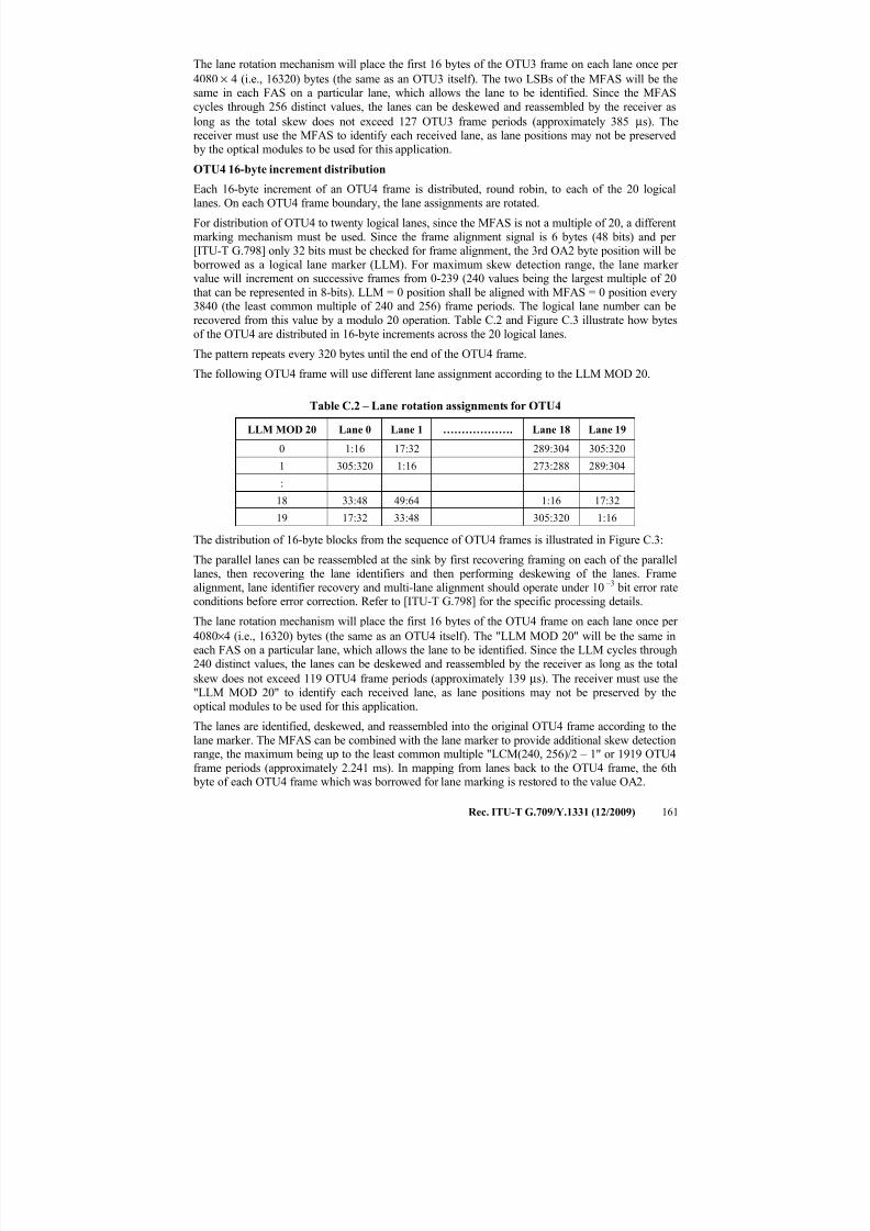
7/16/2019 G-709 ITU_T
http://slidepdf.com/reader/full/g-709-itut 169/218
Rec. ITU-T G.709/Y.1331 (12/2009) 161
The lane rotation mechanism will place the first 16 bytes of the OTU3 frame on each lane once per
4080 × 4 (i.e., 16320) bytes (the same as an OTU3 itself). The two LSBs of the MFAS will be thesame in each FAS on a particular lane, which allows the lane to be identified. Since the MFAS
cycles through 256 distinct values, the lanes can be deskewed and reassembled by the receiver as
long as the total skew does not exceed 127 OTU3 frame periods (approximately 385 μs). Thereceiver must use the MFAS to identify each received lane, as lane positions may not be preserved
by the optical modules to be used for this application.
OTU4 16-byte increment distribution
Each 16-byte increment of an OTU4 frame is distributed, round robin, to each of the 20 logical
lanes. On each OTU4 frame boundary, the lane assignments are rotated.
For distribution of OTU4 to twenty logical lanes, since the MFAS is not a multiple of 20, a different
marking mechanism must be used. Since the frame alignment signal is 6 bytes (48 bits) and per [ITU-T G.798] only 32 bits must be checked for frame alignment, the 3rd OA2 byte position will be
borrowed as a logical lane marker (LLM). For maximum skew detection range, the lane marker value will increment on successive frames from 0-239 (240 values being the largest multiple of 20
that can be represented in 8-bits). LLM = 0 position shall be aligned with MFAS = 0 position every3840 (the least common multiple of 240 and 256) frame periods. The logical lane number can be
recovered from this value by a modulo 20 operation. Table C.2 and Figure C.3 illustrate how bytes
of the OTU4 are distributed in 16-byte increments across the 20 logical lanes.
The pattern repeats every 320 bytes until the end of the OTU4 frame.
The following OTU4 frame will use different lane assignment according to the LLM MOD 20.
Table C.2 – Lane rotation assignments for OTU4
LLM MOD 20 Lane 0 Lane 1 ………………. Lane 18 Lane 19
0 1:16 17:32 289:304 305:320
1 305:320 1:16 273:288 289:304
:
18 33:48 49:64 1:16 17:32
19 17:32 33:48 305:320 1:16
The distribution of 16-byte blocks from the sequence of OTU4 frames is illustrated in Figure C.3:
The parallel lanes can be reassembled at the sink by first recovering framing on each of the parallellanes, then recovering the lane identifiers and then performing deskewing of the lanes. Frame
alignment, lane identifier recovery and multi-lane alignment should operate under 10 –3
bit error rate
conditions before error correction. Refer to [ITU-T G.798] for the specific processing details.
The lane rotation mechanism will place the first 16 bytes of the OTU4 frame on each lane once per
4080×4 (i.e., 16320) bytes (the same as an OTU4 itself). The "LLM MOD 20" will be the same ineach FAS on a particular lane, which allows the lane to be identified. Since the LLM cycles through
240 distinct values, the lanes can be deskewed and reassembled by the receiver as long as the total
skew does not exceed 119 OTU4 frame periods (approximately 139 μs). The receiver must use the
"LLM MOD 20" to identify each received lane, as lane positions may not be preserved by theoptical modules to be used for this application.
The lanes are identified, deskewed, and reassembled into the original OTU4 frame according to the
lane marker. The MFAS can be combined with the lane marker to provide additional skew detectionrange, the maximum being up to the least common multiple "LCM(240, 256)/2 – 1" or 1919 OTU4
frame periods (approximately 2.241 ms). In mapping from lanes back to the OTU4 frame, the 6th byte of each OTU4 frame which was borrowed for lane marking is restored to the value OA2.
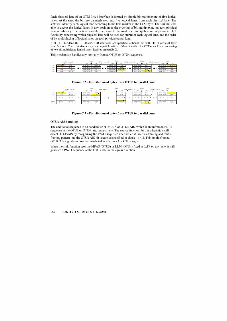
7/16/2019 G-709 ITU_T
http://slidepdf.com/reader/full/g-709-itut 170/218
162 Rec. ITU-T G.709/Y.1331 (12/2009)
Each physical lane of an OTM-0.4v4 interface is formed by simple bit multiplexing of five logical
lanes. At the sink, the bits are disinterleaved into five logical lanes from each physical lane. The
sink will identify each logical lane according to the lane marker in the LLM byte. The sink must beable to accept the logical lanes in any position as the ordering of bit multiplexing on each physical
lane is arbitrary; the optical module hardware to be used for this application is permitted fullflexibility concerning which physical lane will be used for output of each logical lane, and the order
of bit multiplexing of logical lanes on each physical output lane. NOTE 4 – Ten-lane IEEE 100GBASE-R interfaces are specified, although not with ITU-T physical layer
specifications. These interfaces may be compatible with a 10-lane interface for OTU4, each lane consisting
of two bit-multiplexed logical lanes. Refer to Appendix X.
This mechanism handles any normally framed OTU3 or OTU4 sequence.
16305:16320
16289:16304
16263:16288
16247:16272
16305:16320
16289:16304
16263:16288
16247:16272
16305:16320
16289:16304
16263:16288
16247:16272
16305:16320
16289:16304
16263:16288
16247:162721:16 (FAS)
Lane 3
Lane 2
Lane 1
Lane 0
17:32
33:48
49:64
1
65:80
81:96
97:112
113:128
49:64
1:16 (FAS)
17:32
33:48
33:48
49:64
1:16 (FAS)
17:32
17:32
33:48
49:64
1:16 (FAS)
RotateRotateRotate
1:16 (FAS)
17:32
33:48
49:64
Rotate
2 255 256 510 511 765 766 1020 1MFAS = xxxx xx00 MFAS = xxxx xx01 MFAS = xxxx xx10 MFAS = xxxx xx11
Figure C.2 – Distribution of bytes from OTU3 to parallel lanes
16017:16032
16001:160161:16 (FAS)
17:3233:48
49:64 16049:16064
16033:16048
1:16 (FAS)
17:32 16017:16032
16001:16016
1:16 (FAS)
273:288
289:304
305:320 1:16 (FAS)
17:32
289:304
305:320
16017:16032
16001:160161:16 (FAS)
Lane 1
Lane 0
17:32
321:336
337:352
RotateRotateRotate Rotate
16305:16320
16289:16304
Lane 19
Lane 18 289:304
305:320
609:624
625:640
33:48
305:320 16305:16320
16033:16048
1 2 51 52 919 969 770 1020 1LLM MOD 20 = 0 LLM MOD 20 = 1 LLM MOD 20 = 18 LLM MOD 20 = 19
Figure C.3 – Distribution of bytes from OTU4 to parallel lanes
OTUk AIS handling
The additional sequence to be handled is OTU3-AIS or OTU4-AIS, which is an unframed PN-11sequence at the OTU3 or OTU4 rate, respectively. The source function for this adaptation will
detect OTUk-AIS by recognizing the PN-11 sequence after which it inserts a framing and multi-framing pattern into the OTUk AIS bit stream as specified in clause 16.4.2. This (multi)framed
OTUk AIS signal can now be distributed as any non-AIS OTUk signal.
When the sink function sees the MFAS (OTU3) or LLM (OTU4) fixed at 0xFF on any lane, it willgenerate a PN-11 sequence at the OTUk rate in the egress direction.
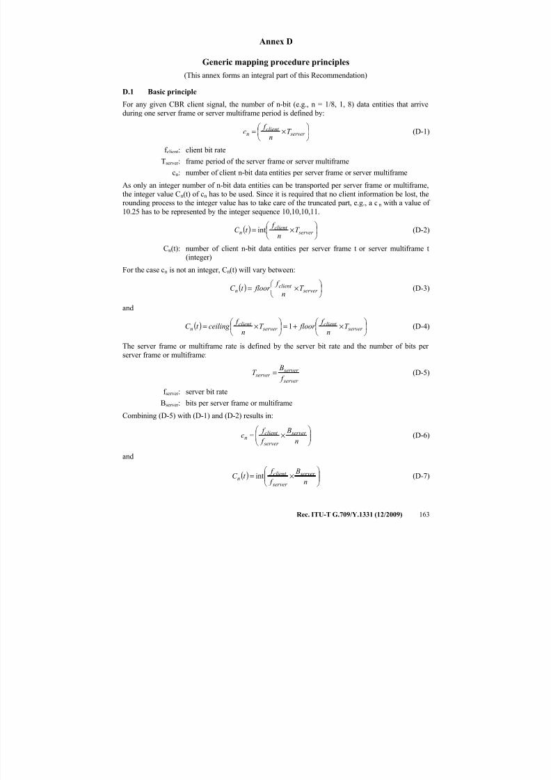
7/16/2019 G-709 ITU_T
http://slidepdf.com/reader/full/g-709-itut 171/218
Rec. ITU-T G.709/Y.1331 (12/2009) 163
Annex D
Generic mapping procedure principles
(This annex forms an integral part of this Recommendation)
D.1 Basic principleFor any given CBR client signal, the number of n-bit (e.g., n = 1/8, 1, 8) data entities that arrive
during one server frame or server multiframe period is defined by:
×= server
client n T
n
f c (D-1)
f client: client bit rate
Tserver : frame period of the server frame or server multiframe
cn: number of client n-bit data entities per server frame or server multiframe
As only an integer number of n-bit data entities can be transported per server frame or multiframe,
the integer value Cn(t) of cn has to be used. Since it is required that no client information be lost, therounding process to the integer value has to take care of the truncated part, e.g., a cn with a value of
10.25 has to be represented by the integer sequence 10,10,10,11.
( )
×= server
client n T
n
f t C int (D-2)
Cn(t): number of client n-bit data entities per server frame t or server multiframe t(integer)
For the case cn is not an integer, Cn(t) will vary between:
( )
×= server
client n T
n f floor t C (D-3)
and
( )
×+=
×= server
client server
client n T
n
f floor T
n
f ceiling t C 1 (D-4)
The server frame or multiframe rate is defined by the server bit rate and the number of bits per
server frame or multiframe:
server
server server
f
BT = (D-5)
f server : server bit rate
Bserver : bits per server frame or multiframe
Combining (D-5) with (D-1) and (D-2) results in:
×=
n
B
f
f c server
server
client n (D-6)
and
( )
×=
n B
f f t C server
server
client n int (D-7)
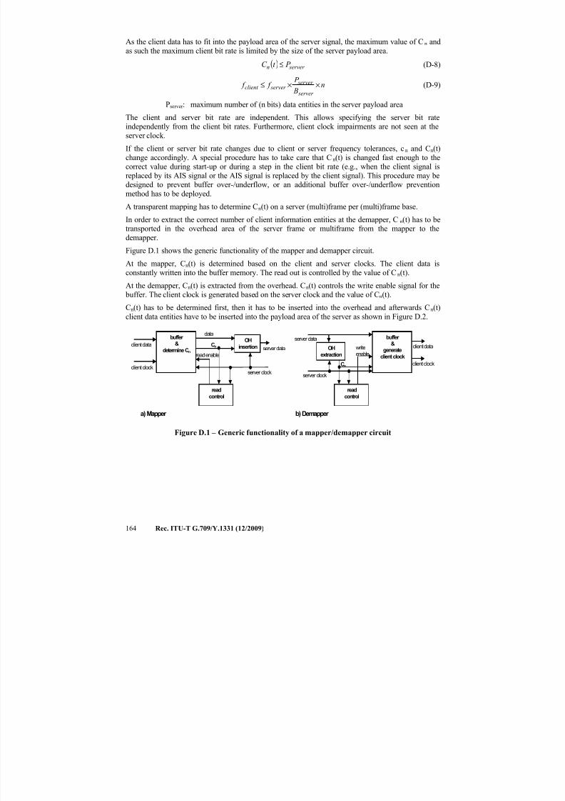
7/16/2019 G-709 ITU_T
http://slidepdf.com/reader/full/g-709-itut 172/218
164 Rec. ITU-T G.709/Y.1331 (12/2009)
As the client data has to fit into the payload area of the server signal, the maximum value of Cn and
as such the maximum client bit rate is limited by the size of the server payload area.
( ) server n P t C ≤ (D-8)
n B
P f f
server
server server client ××≤ (D-9)
Pserver : maximum number of (n bits) data entities in the server payload area
The client and server bit rate are independent. This allows specifying the server bit rateindependently from the client bit rates. Furthermore, client clock impairments are not seen at the
server clock.
If the client or server bit rate changes due to client or server frequency tolerances, cn and Cn(t)
change accordingly. A special procedure has to take care that Cn(t) is changed fast enough to thecorrect value during start-up or during a step in the client bit rate (e.g., when the client signal is
replaced by its AIS signal or the AIS signal is replaced by the client signal). This procedure may bedesigned to prevent buffer over-/underflow, or an additional buffer over-/underflow prevention
method has to be deployed.
A transparent mapping has to determine Cn(t) on a server (multi)frame per (multi)frame base.
In order to extract the correct number of client information entities at the demapper, C n(t) has to betransported in the overhead area of the server frame or multiframe from the mapper to the
demapper.
Figure D.1 shows the generic functionality of the mapper and demapper circuit.
At the mapper, Cn(t) is determined based on the client and server clocks. The client data is
constantly written into the buffer memory. The read out is controlled by the value of Cn(t).
At the demapper, Cn(t) is extracted from the overhead. Cn(t) controls the write enable signal for the
buffer. The client clock is generated based on the server clock and the value of Cn(t).
Cn(t) has to be determined first, then it has to be inserted into the overhead and afterwards Cn(t)
client data entities have to be inserted into the payload area of the server as shown in Figure D.2.
buffer &
determine Cn
readcontrol
OH
insertion
server clock
Cn
client clock
client dataserver data
read enable
data
OH
extraction
buffer &
generate
client clock
readcontrol
server clock
server data
client data
client clockCn
writeenable
a) Mapper b) Demapper
Figure D.1 – Generic functionality of a mapper/demapper circuit
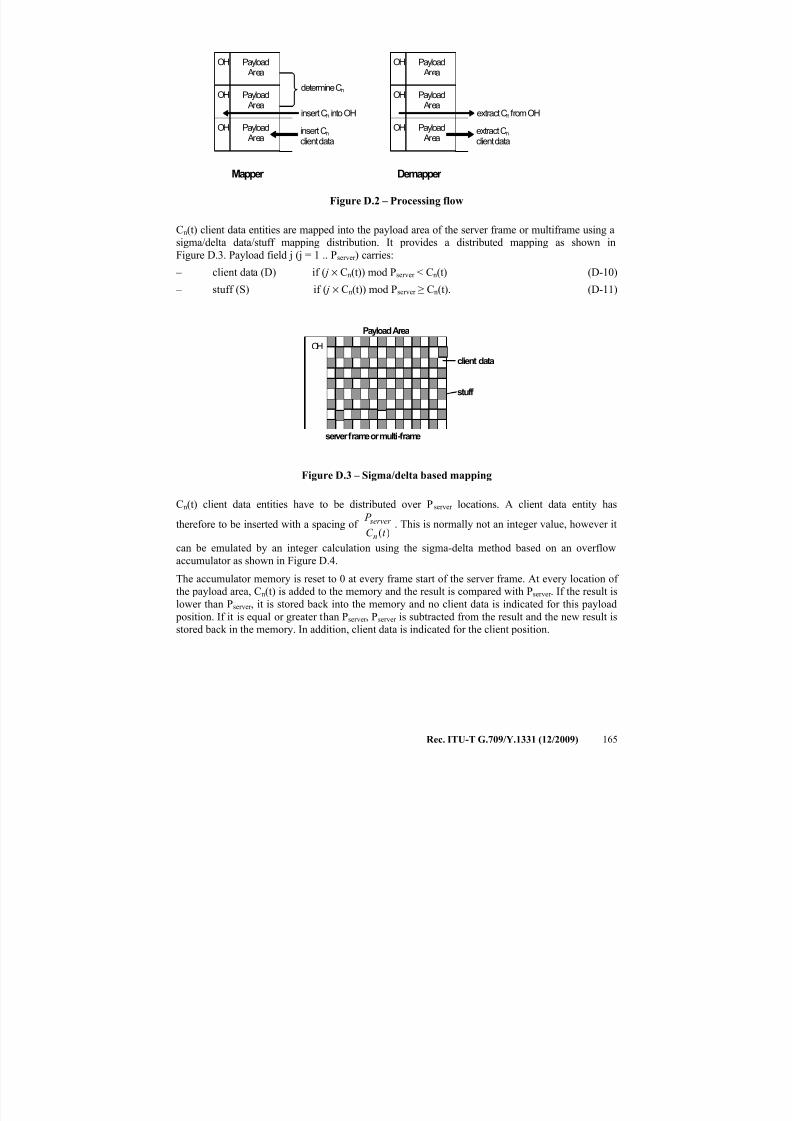
7/16/2019 G-709 ITU_T
http://slidepdf.com/reader/full/g-709-itut 173/218
Rec. ITU-T G.709/Y.1331 (12/2009) 165
determine Cn
Payload Area
OH
Payload Area
OH
Payload
Area
OH insert Cnclient data
insert Cn into OH
Payload Area
OH
Payload Area
OH
Payload
Area
OH extract Cnclient data
extract Cn from OH
Mapper Demapper
Figure D.2 – Processing flow
Cn(t) client data entities are mapped into the payload area of the server frame or multiframe using asigma/delta data/stuff mapping distribution. It provides a distributed mapping as shown in
Figure D.3. Payload field j (j = 1 .. Pserver ) carries:
– client data (D) if ( j × Cn(t)) mod Pserver < Cn(t) (D-10)
– stuff (S) if ( j × Cn(t)) mod Pserver ≥ Cn(t). (D-11)
OH
Payload Area
client data
stuff
server frame or multi-frame
Figure D.3 – Sigma/delta based mapping
Cn(t) client data entities have to be distributed over Pserver locations. A client data entity has
therefore to be inserted with a spacing of )(t C
P
n
server . This is normally not an integer value, however it
can be emulated by an integer calculation using the sigma-delta method based on an overflowaccumulator as shown in Figure D.4.
The accumulator memory is reset to 0 at every frame start of the server frame. At every location of
the payload area, Cn(t) is added to the memory and the result is compared with Pserver . If the result is
lower than Pserver , it is stored back into the memory and no client data is indicated for this payload
position. If it is equal or greater than Pserver , Pserver is subtracted from the result and the new result is
stored back in the memory. In addition, client data is indicated for the client position.
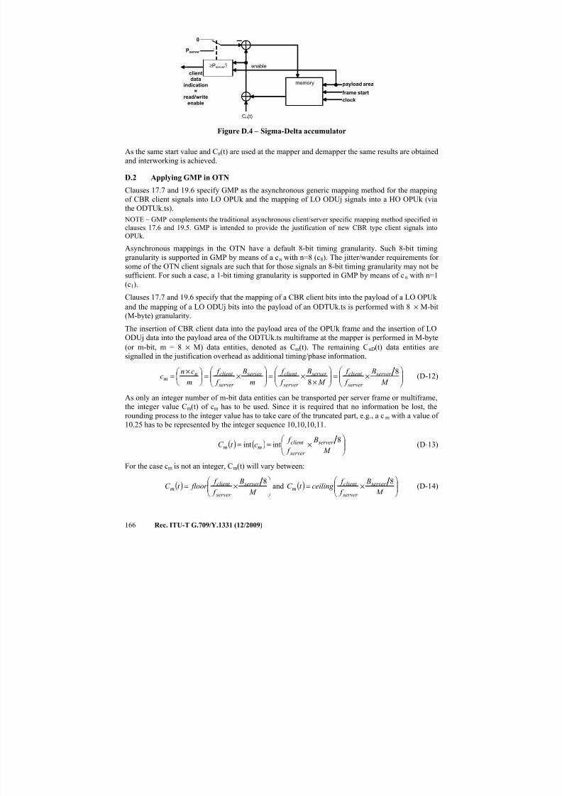
7/16/2019 G-709 ITU_T
http://slidepdf.com/reader/full/g-709-itut 174/218
166 Rec. ITU-T G.709/Y.1331 (12/2009)
0
memory
≥Pserver ?
Pserver
clientdata
indication=
read/writeenable
payload area
frame start
clock
Cn(t)
enable
Figure D.4 – Sigma-Delta accumulator
As the same start value and Cn(t) are used at the mapper and demapper the same results are obtained
and interworking is achieved.
D.2 Applying GMP in OTN
Clauses 17.7 and 19.6 specify GMP as the asynchronous generic mapping method for the mappingof CBR client signals into LO OPUk and the mapping of LO ODUj signals into a HO OPUk (via
the ODTUk.ts).
NOTE – GMP complements the traditional asynchronous client/server specific mapping method specified in
clauses 17.6 and 19.5. GMP is intended to provide the justification of new CBR type client signals into
OPUk.
Asynchronous mappings in the OTN have a default 8-bit timing granularity. Such 8-bit timing
granularity is supported in GMP by means of a cn with n=8 (c8). The jitter/wander requirements for
some of the OTN client signals are such that for those signals an 8-bit timing granularity may not be
sufficient. For such a case, a 1-bit timing granularity is supported in GMP by means of c n with n=1
(c1).
Clauses 17.7 and 19.6 specify that the mapping of a CBR client bits into the payload of a LO OPUk
and the mapping of a LO ODUj bits into the payload of an ODTUk.ts is performed with 8 × M-bit
(M-byte) granularity.
The insertion of CBR client data into the payload area of the OPUk frame and the insertion of LO
ODUj data into the payload area of the ODTUk.ts multiframe at the mapper is performed in M-byte
(or m-bit, m = 8 × M) data entities, denoted as Cm(t). The remaining CnD(t) data entities are
signalled in the justification overhead as additional timing/phase information.
×=
××=
×=
×=
M
B
f
f
M
B
f
f
m
B
f
f
m
cnc server
server
client server
server
client server
server
client nm
8
8(D-12)
As only an integer number of m-bit data entities can be transported per server frame or multiframe,
the integer value Cm(t) of cm has to be used. Since it is required that no information be lost, the
rounding process to the integer value has to take care of the truncated part, e.g., a c m with a value of
10.25 has to be represented by the integer sequence 10,10,10,11.
( ) ( )
×==
M
B
f
f ct C server
server
client mm
8intint (D-13)
For the case cm is not an integer, Cm(t) will vary between:
( )
×=
M B
f f floor t C server
server
client m 8 and ( )
×=
M B
f f ceiling t C server
server
client m 8 (D-14)
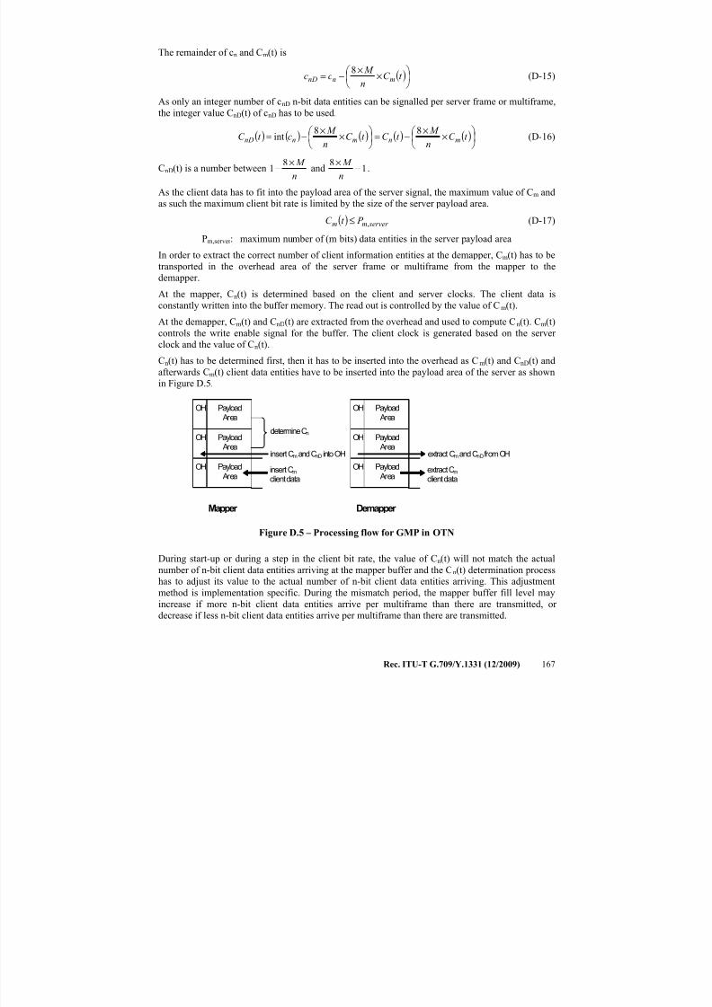
7/16/2019 G-709 ITU_T
http://slidepdf.com/reader/full/g-709-itut 175/218
Rec. ITU-T G.709/Y.1331 (12/2009) 167
The remainder of cn and Cm(t) is
( )
×
×−= t C
n
M cc mnnD
8(D-15)
As only an integer number of cnD n-bit data entities can be signalled per server frame or multiframe,
the integer value CnD(t) of cnD has to be used.
( ) ( ) ( ) ( ) ( )
×
×−=
×
×−= t C
n
M t C t C
n
M ct C mnmnnD
88int (D-16)
CnD(t) is a number betweenn
M ×−
81 and 1
8−
×
n
M .
As the client data has to fit into the payload area of the server signal, the maximum value of Cm and
as such the maximum client bit rate is limited by the size of the server payload area.
( ) server mm P t C ,≤ (D-17)
Pm,server
: maximum number of (m bits) data entities in the server payload area
In order to extract the correct number of client information entities at the demapper, Cm(t) has to be
transported in the overhead area of the server frame or multiframe from the mapper to the
demapper.
At the mapper, Cn(t) is determined based on the client and server clocks. The client data is
constantly written into the buffer memory. The read out is controlled by the value of Cm(t).
At the demapper, Cm(t) and CnD(t) are extracted from the overhead and used to compute Cn(t). Cm(t)
controls the write enable signal for the buffer. The client clock is generated based on the server
clock and the value of Cn(t).
Cn(t) has to be determined first, then it has to be inserted into the overhead as C m(t) and CnD(t) and
afterwards Cm(t) client data entities have to be inserted into the payload area of the server as shown
in Figure D.5.
determine Cn
Payload Area
OH
Payload Area
OH
Payload Area
OH insert Cm
client data
insert Cm and CnD into OH
Payload Area
OH
Payload Area
OH
Payload Area
OH extract Cm
client data
extract Cmand CnDfrom OH
Mapper Demapper
Figure D.5 – Processing flow for GMP in OTN
During start-up or during a step in the client bit rate, the value of Cn(t) will not match the actual
number of n-bit client data entities arriving at the mapper buffer and the Cn(t) determination process
has to adjust its value to the actual number of n-bit client data entities arriving. This adjustment
method is implementation specific. During the mismatch period, the mapper buffer fill level may
increase if more n-bit client data entities arrive per multiframe than there are transmitted, or
decrease if less n-bit client data entities arrive per multiframe than there are transmitted.
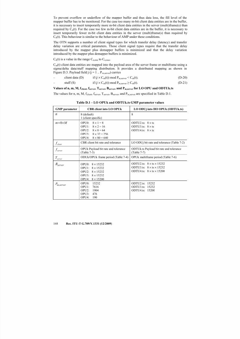
7/16/2019 G-709 ITU_T
http://slidepdf.com/reader/full/g-709-itut 176/218
168 Rec. ITU-T G.709/Y.1331 (12/2009)
To prevent overflow or underflow of the mapper buffer and thus data loss, the fill level of the
mapper buffer has to be monitored. For the case too many m-bit client data entities are in the buffer,
it is necessary to insert temporarily more m-bit client data entities in the server (multi)frame(s) than
required by Cn(t). For the case too few m-bit client data entities are in the buffer, it is necessary to
insert temporarily fewer m-bit client data entities in the server (multi)frame(s) than required by
Cn(t). This behaviour is similar to the behaviour of AMP under these conditions.
The OTN supports a number of client signal types for which transfer delay (latency) and transfer delay variation are critical parameters. Those client signal types require that the transfer delay
introduced by the mapper plus demapper buffers is minimized and that the delay variation
introduced by the mapper plus demapper buffers is minimized.
Cn(t) is a value in the range Cn,min to Cn,max.
Cm(t) client data entities are mapped into the payload area of the server frame or multiframe using a
sigma/delta data/stuff mapping distribution. It provides a distributed mapping as shown in
Figure D.3. Payload field j (j = 1 .. Pm,server ) carries
– client data (D) if ( j × Cm(t)) mod Pm,server < Cm(t); (D-20)
– stuff (S) if ( j × Cm(t)) mod Pm,server ≥ Cm(t). (D-21) Values of n, m, M, f client, f server, Tserver, Bserver, and Pm,server for LO OPU and ODTUk.ts
The values for n, m, M, f client, f server , Tserver , Bserver , and Pm,server are specified in Table D.1.
Table D.1 – LO OPUk and ODTUk.ts GMP parameter values
GMP parameter CBR client into LO OPUk LO ODUj into HO OPUk (ODTUk.ts)
n 8 (default)
1 (client specific)
8
M m ×=8 OPU0: 8 × 1 = 8OPU1: 8 × 2 = 16
OPU2: 8 × 8 = 64
OPU3: 8 × 32 = 256
OPU4: 8 × 80 = 640
ODTU2.ts: 8 × tsODTU3.ts: 8 × ts
ODTU4.ts: 8 × ts
client f CBR client bit rate and tolerance LO ODUj bit rate and tolerance (Table 7-2)
server f OPUk Payload bit rate and tolerance
(Table 7-3)
ODTUk.ts Payload bit rate and tolerance
(Table 7-7)
server T ODUk/OPUk frame period (Table 7-4) OPUk multiframe period (Table 7-6)
server B OPU0: 8 × 15232OPU1: 8 × 15232
OPU2: 8 × 15232
OPU3: 8 × 15232
OPU4: 8 × 15200
ODTU2.ts: 8 × ts × 15232ODTU3.ts: 8 × ts × 15232
ODTU4.ts: 8 × ts × 15200
server m P , OPU0: 15232
OPU1: 7616
OPU2: 1904
OPU3: 476
OPU4: 190
ODTU2.ts: 15232
ODTU3.ts: 15232
ODTU4.ts: 15200
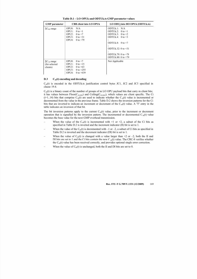
7/16/2019 G-709 ITU_T
http://slidepdf.com/reader/full/g-709-itut 177/218
Rec. ITU-T G.709/Y.1331 (12/2009) 169
Table D.1 – LO OPUk and ODTUk.ts GMP parameter values
GMP parameter CBR client into LO OPUk LO ODUj into HO OPUk (ODTUk.ts)
ΣC8D range OPU0: N/A
OPU1: 0 to +1
OPU2: 0 to +7OPU3: 0 to +31
OPU4: 0 to +79
ODTUk.1: N/A
ODTUk.2: 0 to +1
ODTUk.3: 0 to +2ODTUk.4: 0 to +3
:
ODTUk.8: 0 to +7
:
ODTUk.32: 0 to +31
:
ODTUk.79: 0 to +78
ODTUk.80: 0 to +79
ΣC1D range
(for selected
clients)
OPU0: 0 to +7
OPU1: 0 to +15
OPU2: 0 to +63OPU3: 0 to +255
OPU4: 0 to +639
Not Applicable
D.3 Cm(t) encoding and decoding
Cm(t) is encoded in the ODTUk.ts justification control bytes JC1, JC2 and JC3 specified inclause 19.4.
Cm(t) is a binary count of the number of groups of m LO OPU payload bits that carry m client bits;
it has values between Floor(Cm,min) and Ceiling(Cm,max), which values are client specific. The Ci(i=1..14) bits that comprise Cm(t) are used to indicate whether the Cm(t) value is incremented or
decremented from the value in the previous frame. Table D.2 shows the inversion patterns for the Ci bits that are inverted to indicate an increment or decrement of the Cm(t) value. A "I" entry in the
table indicates an inversion of that bit.
The bit inversion patterns apply to the current Cm(t) value, prior to the increment or decrement
operation that is signalled by the inversion pattern. The incremented or decremented Cm(t) value becomes the base value for the next GMP overhead transmission.
– When the value of the Cm(t) is incremented with +1 or +2, a subset of the Ci bits asspecified in Table D.2 is inverted and the increment indicator (II) bit is set to 1.
– When the value of the Cm(t) is decremented with –1 or –2, a subset of Ci bits as specified in
Table D.2 is inverted and the decrement indicator (DI) bit is set to 1.
– When the value of Cm(t) is changed with a value larger than +2 or –2, both the II andDI bits are set to 1 and the Ci bits contain the new Cm(t) value. The CRC-8 verifies whether the Cm(t) value has been received correctly, and provides optional single error correction.
– When the value of Cm(t) is unchanged, both the II and DI bits are set to 0.
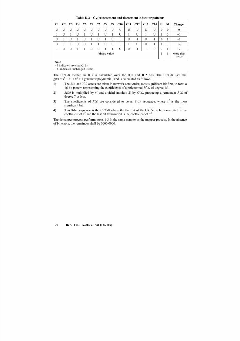
7/16/2019 G-709 ITU_T
http://slidepdf.com/reader/full/g-709-itut 178/218
170 Rec. ITU-T G.709/Y.1331 (12/2009)
Table D.2 – Cm(t) increment and decrement indicator patterns
C1 C2 C3 C4 C5 C6 C7 C8 C9 C10 C11 C12 C13 C14 II DI Change
U U U U U U U U U U U U U U 0 0 0
I U I U I U I U I U I U I U 1 0 +1
U I U I U I U I U I U I U I 0 1 –1
U I I U U I I U U I I U U I 1 0 +2
I U U I I U U I I U U I I U 0 1 –2
binary value 1 1 More than
+2/–2
Note
– I indicates inverted Ci bit
– U indicates unchanged Ci bit
The CRC-8 located in JC3 is calculated over the JC1 and JC2 bits. The CRC-8 uses the
g(x) = x8
+ x3
+ x2
+ 1 generator polynomial, and is calculated as follows:
1) The JC1 and JC2 octets are taken in network octet order, most significant bit first, to form a16-bit pattern representing the coefficients of a polynomial M(x) of degree 15.
2) M(x) is multiplied by x8 and divided (modulo 2) by G(x), producing a remainder R(x) of degree 7 or less.
3) The coefficients of R(x) are considered to be an 8-bit sequence, where x7 is the most
significant bit.
4) This 8-bit sequence is the CRC-8 where the first bit of the CRC-8 to be transmitted is thecoefficient of x7 and the last bit transmitted is the coefficient of x0.
The demapper process performs steps 1-3 in the same manner as the mapper process. In the absence
of bit errors, the remainder shall be 0000 0000.
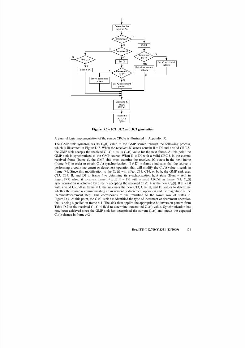
7/16/2019 G-709 ITU_T
http://slidepdf.com/reader/full/g-709-itut 179/218
Rec. ITU-T G.709/Y.1331 (12/2009) 171
Figure D.6 – JC1, JC2 and JC3 generation
A parallel logic implementation of the source CRC-8 is illustrated in Appendix IX.
The GMP sink synchronizes its Cm(t) value to the GMP source through the following process,which is illustrated in Figure D.7. When the received JC octets contain II = DI and a valid CRC-8,
the GMP sink accepts the received C1-C14 as its Cm(t) value for the next frame. At this point theGMP sink is synchronized to the GMP source. When II ≠ DI with a valid CRC-8 in the current
received frame (frame i), the GMP sink must examine the received JC octets in the next frame
(frame i+1) in order to obtain Cm(t) synchronization. II ≠ DI in frame i indicates that the source is
performing a count increment or decrement operation that will modify the Cm(t) value it sends inframe i+1. Since this modification to the Cm(t) will affect C13, C14, or both, the GMP sink usesC13, C14, II, and DI in frame i to determine its synchronization hunt state (Hunt – A-F in
Figure D.7) when it receives frame i+1. If II = DI with a valid CRC-8 in frame i+1, Cm(t)synchronization is achieved by directly accepting the received C1-C14 as the new Cm(t). If II ≠ DI
with a valid CRC-8 in frame i+1, the sink uses the new C13, C14, II, and DI values to determine
whether the source is communicating an increment or decrement operation and the magnitude of theincrement/decrement step. This corresponds to the transition to the lower row of states inFigure D.7. At this point, the GMP sink has identified the type of increment or decrement operation
that is being signalled in frame i+1. The sink then applies the appropriate bit inversion pattern fromTable D.2 to the received C1-C14 field to determine transmitted Cm(t) value. Synchronization has
now been achieved since the GMP sink has determined the current Cm(t) and knows the expectedCm(t) change in frame i+2.
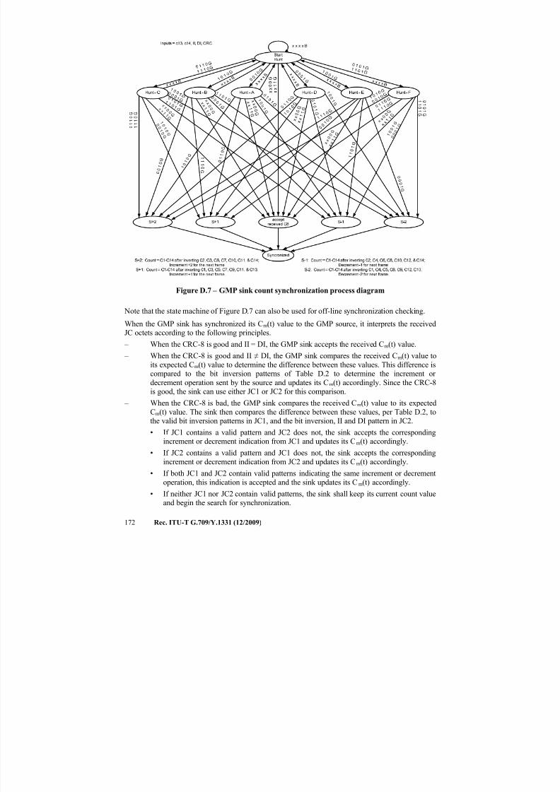
7/16/2019 G-709 ITU_T
http://slidepdf.com/reader/full/g-709-itut 180/218
172 Rec. ITU-T G.709/Y.1331 (12/2009)
x x x x
B
1 0 1 0 G
1 0 0 1 G
x x 0
0 G
x x 1 1 G
1 0 1 0 G
0 0 1 0 G
1
0 0 1 G
1 0 0 1 G
0 0 0 1 G
x x 0
0 G
x x 1
1 G
Figure D.7 – GMP sink count synchronization process diagram
Note that the state machine of Figure D.7 can also be used for off-line synchronization checking.
When the GMP sink has synchronized its Cm(t) value to the GMP source, it interprets the receivedJC octets according to the following principles.
– When the CRC-8 is good and II = DI, the GMP sink accepts the received Cm(t) value.
– When the CRC-8 is good and II ≠ DI, the GMP sink compares the received Cm(t) value to
its expected Cm(t) value to determine the difference between these values. This difference iscompared to the bit inversion patterns of Table D.2 to determine the increment or
decrement operation sent by the source and updates its Cm(t) accordingly. Since the CRC-8is good, the sink can use either JC1 or JC2 for this comparison.
– When the CRC-8 is bad, the GMP sink compares the received Cm(t) value to its expected
Cm(t) value. The sink then compares the difference between these values, per Table D.2, tothe valid bit inversion patterns in JC1, and the bit inversion, II and DI pattern in JC2.
• If JC1 contains a valid pattern and JC2 does not, the sink accepts the correspondingincrement or decrement indication from JC1 and updates its Cm(t) accordingly.
• If JC2 contains a valid pattern and JC1 does not, the sink accepts the corresponding
increment or decrement indication from JC2 and updates its Cm(t) accordingly.
• If both JC1 and JC2 contain valid patterns indicating the same increment or decrement
operation, this indication is accepted and the sink updates its Cm(t) accordingly.
• If neither JC1 nor JC2 contain valid patterns, the sink shall keep its current count valueand begin the search for synchronization.
7/16/2019 G-709 ITU_T
http://slidepdf.com/reader/full/g-709-itut 181/218
Rec. ITU-T G.709/Y.1331 (12/2009) 173
NOTE – If JC1 and JC2 each contain valid patterns that are different from each other, the receiver
can either keep the current Cm(t) value and begin a synchronization search, or it can use the CRC-8
to determine whether JC1 or JC2 contains the correct pattern.
The GMP sink uses the updated Cm(t) value to extract the client data from the next LO OPU frame
or ODTUk.ts multiframe.
D.4 ΣCnD(t) encoding and decoding
The cumulative value of CnD(t) (ΣCnD(t)) is encoded in bits 4-8 of the LO OPUk and ODTUk.ts justification control bytes JC4, JC5 and JC6. Bits D1 to D10 in JC4 and JC5 carry the value of
ΣCnD(t). Bit D1 carries the most significant bit and bit D10 carries the least significant bit.
The CRC-5 located in JC6 is calculated over the D1-D10 bits in JC4 and JC5. The CRC-5 uses theg(x) = x5 + x + 1 generator polynomial, and is calculated as follows:
1) The JC4 bits 4-8 and JC5 bits 4-8 octets are taken in network transmission order, most
significant bit first, to form a 10-bit pattern representing the coefficients of a polynomial M(x) of degree 9.
2) M(x) is multiplied by x5
and divided (modulo 2) by G(x), producing a remainder R(x) of degree 4 or less.
3) The coefficients of R(x) are considered to be an 8-bit sequence, where x4 is the mostsignificant bit.
4) This 5-bit sequence is the CRC-5 where the first bit of the CRC-5 to be transmitted is the
coefficient of x4
and the last bit transmitted is the coefficient of x0.
The demapper process performs steps 1-3 in the same manner as the mapper process. In the absenceof bit errors, the remainder shall be 00000.
A parallel logic implementation of the source CRC-5 is illustrated in Appendix IX.
7/16/2019 G-709 ITU_T
http://slidepdf.com/reader/full/g-709-itut 182/218
174 Rec. ITU-T G.709/Y.1331 (12/2009)
Appendix I
Range of stuff ratios for asynchronous mappings of CBR2G5, CBR10G, and
CBR40G clients with ±20 ppm bit-rate tolerance into OPUk, and for
asynchronous multiplexing of ODUj into ODUk (k > j)
(This appendix does not form an integral part of this Recommendation)
Clause 17.2 describes asynchronous and bit synchronous mappings of CBR2G5, CBR10G, and
CBR40G clients with ±20 ppm bit-rate tolerance into ODU1, 2, and 3, respectively. Clause 19
describes asynchronous mapping (multiplexing) of ODUj into ODUk (k > j). For asynchronousCBR client mappings, any frequency difference between the client and local OPUk server clocks is
accommodated by the +1/0/–1 justification scheme. For asynchronous multiplexing of ODUj intoODUk (k > j), any frequency difference between the client ODUj and local OPUk server clocks is
accommodated by the +2/+1/0/–1 justification scheme. The OPUk payload, ODUk, and OTUk bitrates and tolerances are given in clause 7.3. The ODU1, ODU2, and ODU3 rates are 239/238,
239/237, and 239/236 times 2 488 320 kbit/s, 9 953 280 kbit/s, and 39 813 120 kbit/s, respectively.The ODUk bit-rate tolerances are ±20 ppm. This appendix shows that each justification scheme canaccommodate these bit rates and tolerances for the respective mappings, and also derives the rangeof justification (stuff) ratio for each mapping.
The +1/0/–1 mapping in clause 17.2 provides for one positive justification opportunity (PJO) and
one negative justification opportunity (NJO) in each ODUk frame. The +2/+1/0/–1 mapping in
clause 19 provides for 2 PJOs and one NJO in each ODUk frame. For the case of ODUmultiplexing (i.e., the latter case), the ODUj being mapped will get only a fraction of the full
payload capacity of the ODUk. There can be, in general, a number of fixed stuff bytes per ODUj or CBR client. Note that in both mapping cases, there is one stuff opportunity in every ODUk frame.
For mapping of a CBR client into ODUk, the CBR client is allowed to use all the stuff opportunities(because only one CBR client signal is mapped into an ODUk). However, for mapping ODUj into
ODUk (k > j), the ODUj can only use 1/2 (ODU0 into ODU1), 1/4 (ODU1 into ODU2 or ODU2
into ODU3) or 1/16 (ODU1 into ODU3) of the stuff opportunities. The other stuff opportunities areneeded for the other clients being multiplexed into the ODUk.
Traditionally, the justification ratio (stuff ratio) for purely positive justification schemes is defined
as the long-run average fraction of justification opportunities for which a justification is done(i.e., for a very large number of frames, the ratio of the number of justifications to the total number
of justification opportunities). In the +1/0/–1 scheme, positive and negative justifications must bedistinguished. This is done by using different algebraic signs for positive and negative justifications.
With this convention, the justification ratio can vary at most (for sufficiently large frequency
offsets) from –1 to +1 (in contrast to a purely positive justification scheme, where justification ratiocan vary at most from 0 to 1). In the case of ODUk multiplexing, the justification ratio is defined
relative to the stuff opportunities available for the client in question. Then, the justification ratio canvary (for sufficiently large frequency offsets) from –1 to +2. (If the justification ratio were defined
relative to all the stuff opportunities for all the clients, the range would be –1/2 to +1 for multiplexing ODU0 into ODU1, –1/4 to +1/2 for multiplexing ODU1 into ODU2 and ODU2 intoODU3, and –1/16 to +1/8 for multiplexing ODU1 into ODU3.)
Let α represent justification ratio (−1 ≤ α ≤ 1 for CBR client into ODUk mapping; –2 ≤ α ≤ 1 for
ODUj into ODUk mapping (k > j)), and use the further convention that positive α will correspond
to negative justification and negative α to positive justification (the reason for this convention is
explained below).
7/16/2019 G-709 ITU_T
http://slidepdf.com/reader/full/g-709-itut 183/218
Rec. ITU-T G.709/Y.1331 (12/2009) 175
Define the following notation (the index j refers to the possible ODUj client being mapped, and the
index k refers to the ODUk server layer into which the ODUj or CBR client is mapped):
N = number of fixed stuff bytes in the OPUk payload area associated with the
client in question (note that this is not the total number of fixed stuff bytes if multiple clients are being multiplexed)
S = nominal STM-N or ODUj client rate (bytes/s)
T = nominal ODUk frame period(s)
yc = client frequency offset (fraction)
y s = server frequency offset (fraction)
p = fraction of OPUk payload area available to this client
N f = average number of client bytes mapped into an ODUk frame, for the particular frequency offsets (averaged over a large number of frames)
Then N f is given by:
s
c
f y
y
ST N +
+
= 1
1
(I-1)
For frequency offsets small compared to 1, this may be approximated:
β≡−+= ST y yST N sc f )1( (I-2)
The quantity β –1 is the net frequency offset due to client and server frequency offset.
Now, the average number of client bytes mapped into an ODUk frame is also equal to the totalnumber of bytes in the payload area available to this client (which is (4)(3808) p = 15232 p), minus
the number of fixed stuff bytes for this client ( N ), plus the average number of bytes stuffed for this
client over a very large number of frames. The latter is equal to the justification ratio α multiplied
by the fraction of frames p corresponding to justification opportunities for this client. Combiningthis with equation I-1 produces:
N p pST −+α=β 15232 (I-3)
In equation I-3, a positive α corresponds to more client bytes mapped into the ODUk, on average.
As indicated above, this corresponds to negative justification. This sign convention is used so that α enters in equation I-3 with a positive sign (for convenience).
Equation I-3 is the main result. For mapping STM-N (CBR clients) into ODUk, the quantity p is 1.
The range of stuff ratio may now be determined for mapping STM-N or ODUj clients into ODUk,using equation I-3. In what follows, let R16 be the STM-16 rate, i.e., 2.48832 Gbit/s =
3.1104 × 108 bytes/s.
Asynchronous mapping of CBR2G5 (2 488 320 kbit/s) signal into ODU1
The nominal client rate is S = R16. The nominal ODU1 rate is (239/238)S (see clause 7.3). But thenominal ODU1 rate is also equal to (4)(3824)/T. Then:
15232239
238)3824)(4(ST == (I-4)
Inserting this into equation I-3, and using the fact that N = 0 (no fixed stuff bytes) for this mapping
produces
)1(15232 −β=α (I-5)
7/16/2019 G-709 ITU_T
http://slidepdf.com/reader/full/g-709-itut 184/218
176 Rec. ITU-T G.709/Y.1331 (12/2009)
Since the ODUk and client frequency tolerances are each ±20 ppm, β ranges from 0.99996 to
1.00004. Using this in equation I-5 gives as the range of α:
60928.060928.0 +≤α≤− (I-6)
Asynchronous mapping of CBR10G (9 953 280 kbit/s) signal into ODU2
The nominal client rate is S = 4 R16. The nominal ODU2 rate is (239/237)S (see clause 7.3). But the
nominal ODU2 rate is also equal to (4)(3824)/T. Then:
15168239
237)3824)(4( ==ST (I-7)
Inserting this into equation I-3, and using the fact that N = 64 (number of fixed stuff bytes) for thismapping produces:
)1(15168152326415168 −β=−+β=α (I-8)
As before, the ODUk and client frequency tolerances are ±20 ppm, and β ranges from 0.99996 to
1.00004. Using this in equation I-8 gives as the range of α:
60672.060672.0 +≤α≤− (I-9)
Asynchronous mapping of CBR40G (39 813 120 kbit/s) signal into ODU3
The nominal client rate is S = 16 R16. The nominal ODU3 rate is (239/236)S (see clause 7.3). But the
nominal ODU3 rate is also equal to (4)(3824)/T. Then:
15104239
236)3824)(4(ST == (I-10)
Inserting this into equation I-3, and using the fact that N = 128 (number of fixed stuff bytes) for thismapping produces:
)1(151041523212815104 −β=−+β=α (I-11)
As before, the ODUk and client frequency tolerances are ±20 ppm, and β ranges from 0.99996 to
1.00004. Using this in equation I-11 gives as the range of α:
60416.060416.0 +≤α≤− (I-12)
ODU1 into ODU2 multiplexing
The ODU1 nominal client rate is (see clause 7.3):
16R 238
239S = (I-13)
The ODU2 nominal frame time is:
)R 4(237
239
)4)(3824(T
16
= (I-14)
The fraction p is 0.25. Inserting into equation I-3 produces:
N38084
)R 4(237
239
)4)(3824(R
238
239
16
16 −+α
=β (I-15)
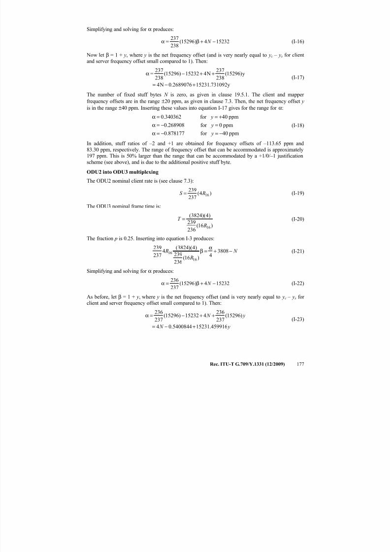
7/16/2019 G-709 ITU_T
http://slidepdf.com/reader/full/g-709-itut 185/218
Rec. ITU-T G.709/Y.1331 (12/2009) 177
Simplifying and solving for α produces:
152324)15296(238
237−+β=α N (I-16)
Now let β = 1 + y, where y is the net frequency offset (and is very nearly equal to yc – y s for clientand server frequency offset small compared to 1). Then:
y731092.152312689076.0 N4
y)15296(238
237 N415232)15296(
238
237
+−=
++−=α(I-17)
The number of fixed stuff bytes N is zero, as given in clause 19.5.1. The client and mapper
frequency offsets are in the range ±20 ppm, as given in clause 7.3. Then, the net frequency offset y
is in the range ±40 ppm. Inserting these values into equation I-17 gives for the range for α:
ppm40for 878177.0
ppm0for 0.268908
ppm40for 340362.0
−=−=α
=−=α
+==α
y
y
y
(I-18)
In addition, stuff ratios of –2 and +1 are obtained for frequency offsets of –113.65 ppm and
83.30 ppm, respectively. The range of frequency offset that can be accommodated is approximately197 ppm. This is 50% larger than the range that can be accommodated by a +1/0/–1 justification
scheme (see above), and is due to the additional positive stuff byte.
ODU2 into ODU3 multiplexing
The ODU2 nominal client rate is (see clause 7.3):
)4(237
23916 RS = (I-19)
The ODU3 nominal frame time is:
)16(236
239
)4)(3824(
16 R
T = (I-20)
The fraction p is 0.25. Inserting into equation I-3 produces:
N
R
R −+α
=β 38084
)16(236
239
)4)(3824(4
237
239
16
16 (I-21)
Simplifying and solving for α produces:
152324)15296(237
236−+β=α N (I-22)
As before, let β = 1 + y, where y is the net frequency offset (and is very nearly equal to yc – y s for client and server frequency offset small compared to 1). Then:
y N
y N
459916.152315400844.04
)15296(237
236415232)15296(
237
236
+−=
++−=α(I-23)
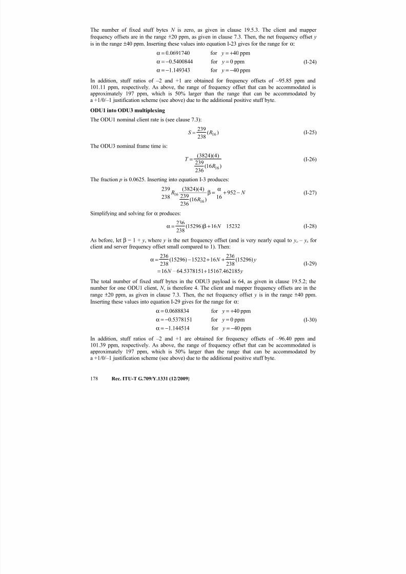
7/16/2019 G-709 ITU_T
http://slidepdf.com/reader/full/g-709-itut 186/218
178 Rec. ITU-T G.709/Y.1331 (12/2009)
The number of fixed stuff bytes N is zero, as given in clause 19.5.3. The client and mapper
frequency offsets are in the range ±20 ppm, as given in clause 7.3. Then, the net frequency offset y
is in the range ±40 ppm. Inserting these values into equation I-23 gives for the range for α:
ppm40for 149343.1
ppm0for 4540084.0
ppm40for 0691740.0
−=−=α
=−=α
+==α
y
y
y
(I-24)
In addition, stuff ratios of –2 and +1 are obtained for frequency offsets of –95.85 ppm and
101.11 ppm, respectively. As above, the range of frequency offset that can be accommodated isapproximately 197 ppm, which is 50% larger than the range that can be accommodated by
a +1/0/–1 justification scheme (see above) due to the additional positive stuff byte.
ODU1 into ODU3 multiplexing
The ODU1 nominal client rate is (see clause 7.3):
)(
238
23916 RS = (I-25)
The ODU3 nominal frame time is:
)16(236
239
)4)(3824(
16 R
T = (I-26)
The fraction p is 0.0625. Inserting into equation I-3 produces:
N
R
R −+α
=β 95216)16(
236
239
)4)(3824(
238
239
16
16 (I-27)
Simplifying and solving for α produces:
1523216)15296(238
236−+β=α N (I-28)
As before, let β = 1 + y, where y is the net frequency offset (and is very nearly equal to yc – y s for client and server frequency offset small compared to 1). Then:
y N
y N
462185.151675378151.6416
)15296(238
2361615232)15296(
238
236
+−=
++−=α(I-29)
The total number of fixed stuff bytes in the ODU3 payload is 64, as given in clause 19.5.2; the
number for one ODU1 client, N , is therefore 4. The client and mapper frequency offsets are in the
range ±20 ppm, as given in clause 7.3. Then, the net frequency offset y is in the range ±40 ppm.
Inserting these values into equation I-29 gives for the range for α:
ppm40for 144514.1
ppm0for 5378151.0
ppm40for 0688834.0
−=−=α
=−=α
+==α
y
y
y
(I-30)
In addition, stuff ratios of –2 and +1 are obtained for frequency offsets of –96.40 ppm and101.39 ppm, respectively. As above, the range of frequency offset that can be accommodated is
approximately 197 ppm, which is 50% larger than the range that can be accommodated bya +1/0/–1 justification scheme (see above) due to the additional positive stuff byte.
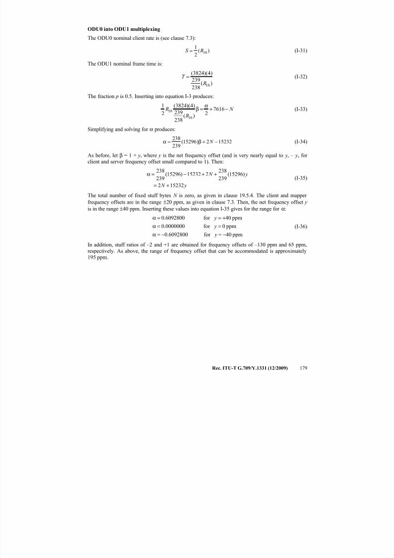
7/16/2019 G-709 ITU_T
http://slidepdf.com/reader/full/g-709-itut 187/218
Rec. ITU-T G.709/Y.1331 (12/2009) 179
ODU0 into ODU1 multiplexing
The ODU0 nominal client rate is (see clause 7.3):
)(2
116 RS = (I-31)
The ODU1 nominal frame time is:
)(238
239
)4)(3824(
16 R
T = (I-32)
The fraction p is 0.5. Inserting into equation I-3 produces:
N
R
R −+α
=β 76162)(
238
239
)4)(3824(
2
1
16
16 (I-33)
Simplifying and solving for α produces:
152322)15296(239
238−+β=α N (I-34)
As before, let β = 1 + y, where y is the net frequency offset (and is very nearly equal to yc – y s for
client and server frequency offset small compared to 1). Then:
y N
y N
152322
)15296(239
238215232)15296(
239
238
+=
++−=α(I-35)
The total number of fixed stuff bytes N is zero, as given in clause 19.5.4. The client and mapper
frequency offsets are in the range ±20 ppm, as given in clause 7.3. Then, the net frequency offset y is in the range ±40 ppm. Inserting these values into equation I-35 gives for the range for α:
ppm40for 6092800.0
ppm0for 0000000.0
ppm40for 6092800.0
−=−=α
==α
+==α
y
y
y
(I-36)
In addition, stuff ratios of –2 and +1 are obtained for frequency offsets of –130 ppm and 65 ppm,
respectively. As above, the range of frequency offset that can be accommodated is approximately195 ppm.
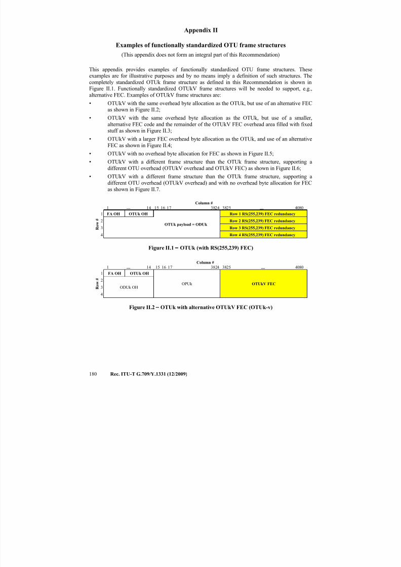
7/16/2019 G-709 ITU_T
http://slidepdf.com/reader/full/g-709-itut 188/218
180 Rec. ITU-T G.709/Y.1331 (12/2009)
Appendix II
Examples of functionally standardized OTU frame structures
(This appendix does not form an integral part of this Recommendation)
This appendix provides examples of functionally standardized OTU frame structures. Theseexamples are for illustrative purposes and by no means imply a definition of such structures. The
completely standardized OTUk frame structure as defined in this Recommendation is shown inFigure II.1. Functionally standardized OTUkV frame structures will be needed to support, e.g.,
alternative FEC. Examples of OTUkV frame structures are:
• OTUkV with the same overhead byte allocation as the OTUk, but use of an alternative FECas shown in Figure II.2;
• OTUkV with the same overhead byte allocation as the OTUk, but use of a smaller,
alternative FEC code and the remainder of the OTUkV FEC overhead area filled with fixedstuff as shown in Figure II.3;
• OTUkV with a larger FEC overhead byte allocation as the OTUk, and use of an alternativeFEC as shown in Figure II.4;
• OTUkV with no overhead byte allocation for FEC as shown in Figure II.5;
• OTUkV with a different frame structure than the OTUk frame structure, supporting a
different OTU overhead (OTUkV overhead and OTUkV FEC) as shown in Figure II.6;
• OTUkV with a different frame structure than the OTUk frame structure, supporting a
different OTU overhead (OTUkV overhead) and with no overhead byte allocation for FECas shown in Figure II.7.
Column #
1 .... 14 15 16 17 3824 3825 .... 4080
R o w
#
1 FA OH OTUk OH
OTUk payload = ODUk
Row 1 RS(255,239) FEC redundancy
2 Row 2 RS(255,239) FEC redundancy
3 Row 3 RS(255,239) FEC redundancy
4 Row 4 RS(255,239) FEC redundancy
Figure II.1 − OTUk (with RS(255,239) FEC)
Column #
1 .... 14 15 16 17 3824 3825 .... 4080
R o w
#1 FA OH OTUk OH
OPUk OTUkV FEC2
ODUk OH3
4
Figure II.2 − OTUk with alternative OTUkV FEC (OTUk-v)
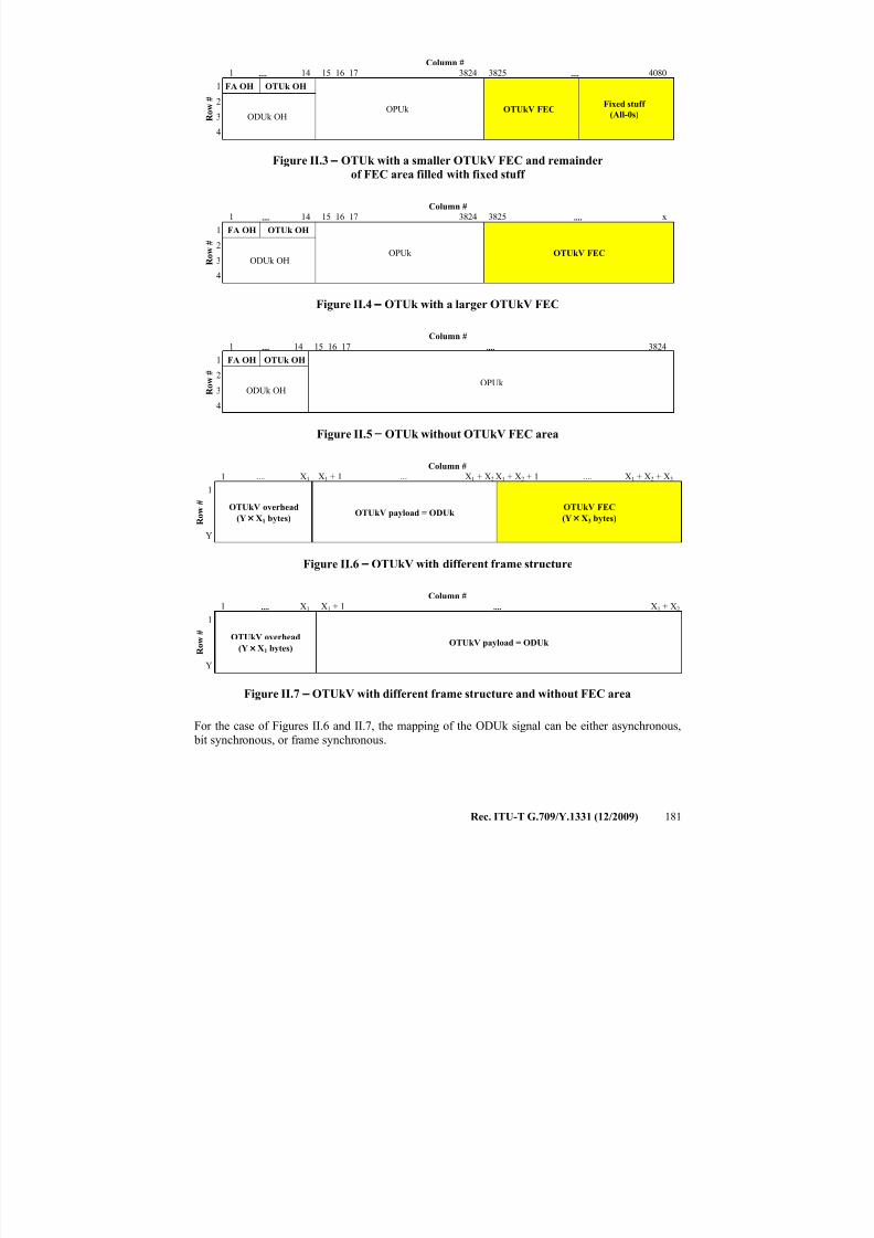
7/16/2019 G-709 ITU_T
http://slidepdf.com/reader/full/g-709-itut 189/218
Rec. ITU-T G.709/Y.1331 (12/2009) 181
Column #
1 .... 14 15 16 17 3824 3825 .... 4080
R o w
#
1 FA OH OTUk OH
OPUk OTUkV FECFixed stuff
(All-0s)
2
ODUk OH3
4
Figure II.3 − OTUk with a smaller OTUkV FEC and remainder
of FEC area filled with fixed stuff
Column #
1 .... 14 15 16 17 3824 3825 .... x
R o w
#
1 FA OH OTUk OH
OPUk OTUkV FEC2
ODUk OH3
4
Figure II.4 − OTUk with a larger OTUkV FEC
Column #
1 .... 14 15 16 17 .... 3824
R o w
#
1 FA OH OTUk OH
OPUk 2
ODUk OH3
4
Figure II.5 − OTUk without OTUkV FEC area
Column #
1 .... X1 X1 + 1 .... X1 + X2 X1 + X2 + 1 .... X1 + X2 + X3
R o w
#
1
OTUkV overhead
(Y × X1 bytes)OTUkV payload = ODUk
OTUkV FEC
(Y × X3 bytes)
Y
Figure II.6 − OTUkV with different frame structure
Column #
1 .... X1 X1 + 1 .... X1 + X2
R o w
#
1
OTUkV overhead
(Y × X1 bytes)OTUkV payload = ODUk
Y
Figure II.7 − OTUkV with different frame structure and without FEC area
For the case of Figures II.6 and II.7, the mapping of the ODUk signal can be either asynchronous,
bit synchronous, or frame synchronous.
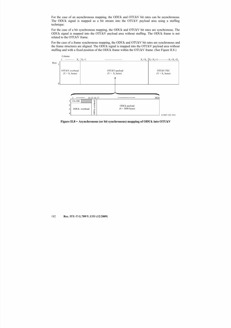
7/16/2019 G-709 ITU_T
http://slidepdf.com/reader/full/g-709-itut 190/218
182 Rec. ITU-T G.709/Y.1331 (12/2009)
For the case of an asynchronous mapping, the ODUk and OTUkV bit rates can be asynchronous.
The ODUk signal is mapped as a bit stream into the OTUkV payload area using a stuffingtechnique.
For the case of a bit synchronous mapping, the ODUk and OTUkV bit rates are synchronous. The
ODUk signal is mapped into the OTUkV payload area without stuffing. The ODUk frame is not
related to the OTUkV frame.
For the case of a frame synchronous mapping, the ODUk and OTUkV bit rates are synchronous andthe frame structures are aligned. The ODUk signal is mapped into the OTUkV payload area without
stuffing and with a fixed position of the ODUk frame within the OTUkV frame. (See Figure II.8.)
G.709/Y.1331_FII.8
OTUkV overhead
(Y × X1 bytes)
OTUkV payload
(Y × X2 bytes)
OTUkV FEC
(Y × X3 bytes)
O P U k o v e r h e a d
ODUk overhead
ODUk payload(4 × 3808 bytes)
X1 X1+1 X1+X2 X1+X2+1 X1+X2+X3
1
2
3
4
3824
1
Y
1
1
FA OH
14 15 16 17
Column
Row
Figure II.8 − Asynchronous (or bit synchronous) mapping of ODUk into OTUkV
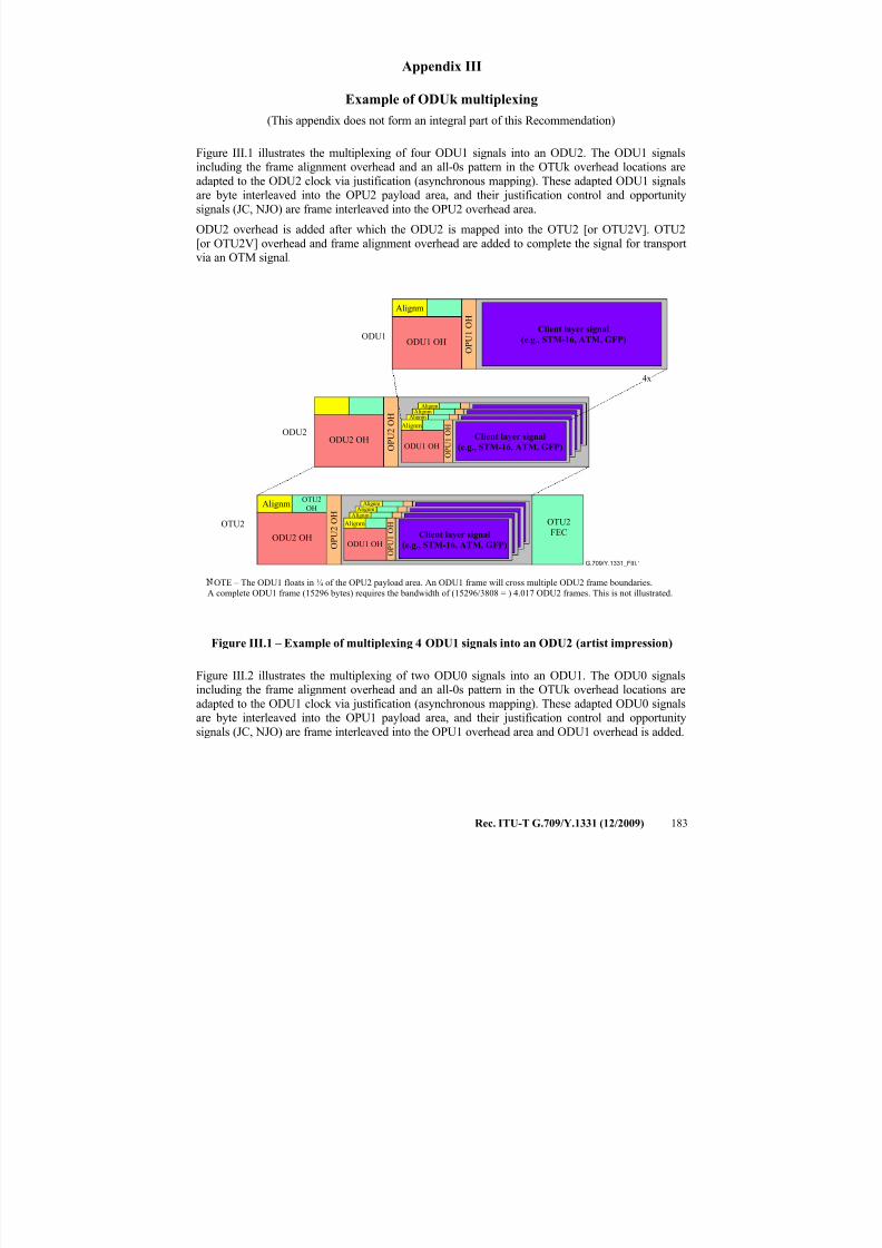
7/16/2019 G-709 ITU_T
http://slidepdf.com/reader/full/g-709-itut 191/218
Rec. ITU-T G.709/Y.1331 (12/2009) 183
Appendix III
Example of ODUk multiplexing
(This appendix does not form an integral part of this Recommendation)
Figure III.1 illustrates the multiplexing of four ODU1 signals into an ODU2. The ODU1 signalsincluding the frame alignment overhead and an all-0s pattern in the OTUk overhead locations are
adapted to the ODU2 clock via justification (asynchronous mapping). These adapted ODU1 signalsare byte interleaved into the OPU2 payload area, and their justification control and opportunity
signals (JC, NJO) are frame interleaved into the OPU2 overhead area.
ODU2 overhead is added after which the ODU2 is mapped into the OTU2 [or OTU2V]. OTU2
[or OTU2V] overhead and frame alignment overhead are added to complete the signal for transportvia an OTM signal.
G.709/Y.1331_FIII.1
OTU2
Client layer signal
(e.g., STM-16, ATM, GFP)ODU1ODU1 OH
Alignm
ODU2
O P U 1 O H
ODU2 OH O P U 2 O H
OTE – The ODU1 floats in ¼ of the OPU2 payload area. An ODU1 frame will cross multiple ODU2 frame boundaries.
A complete ODU1 frame (15296 bytes) requires the bandwidth of (15296/3808 = ) 4.017 ODU2 frames. This is not illustrated.
OTU2
FEC
Client layer signal
(e.g., STM-16, ATM, GFP)ODU1 OH
O
P U 1 O HAlignm
4x
ODU2 OH O P U 2 O H
Client layer signal
(e.g., STM-16, ATM, GFP)ODU1 OH
O P U 1 O HAlignm
AlignmAlignm
Alignm
AlignmAlignm
Alignm
AlignmOTU2
OH
Figure III.1 – Example of multiplexing 4 ODU1 signals into an ODU2 (artist impression)
Figure III.2 illustrates the multiplexing of two ODU0 signals into an ODU1. The ODU0 signalsincluding the frame alignment overhead and an all-0s pattern in the OTUk overhead locations are
adapted to the ODU1 clock via justification (asynchronous mapping). These adapted ODU0 signalsare byte interleaved into the OPU1 payload area, and their justification control and opportunity
signals (JC, NJO) are frame interleaved into the OPU1 overhead area and ODU1 overhead is added.
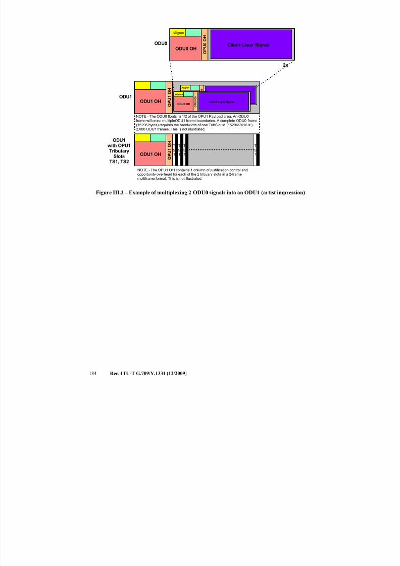
7/16/2019 G-709 ITU_T
http://slidepdf.com/reader/full/g-709-itut 192/218
184 Rec. ITU-T G.709/Y.1331 (12/2009)
Client Layer SignalODU0ODU0 OH
ODU1
2x
O P U 0 O H
Client Layer Signal(GFP-T encapsulated 1GE)ODU1 OH
Alignm
O P U 0 O H
Client Layer SignalODU0 OH
Alignm
O P U 0 O H
ODU1 OH O P U 1 O H
NOTE - The ODU0 floats in 1/2 of the OPU1 Payload area. An ODU0frame will cross multipleODU1 frame boundaries. A complete ODU0 frame(15296 bytes) requires the bandwidth of one TribSlot in (15296/7616 = )2.008 ODU1 frames. This is not i llustrated.
ODU1 OH O P U 1 O H
T
S1
T
S2
T
S1
T
S2
T
S1
T
S2
T
S1
T
S2
ODU1with OPU1Tributary
SlotsTS1, TS2
NOTE - The OPU1 OH contains 1 column of justification control andopportunity overhead for each of the 2 tribuary slots in a 2-framemultiframe format. This is not illustrated.
Alignm
Figure III.2 – Example of multiplexing 2 ODU0 signals into an ODU1 (artist impression)

7/16/2019 G-709 ITU_T
http://slidepdf.com/reader/full/g-709-itut 193/218
Rec. ITU-T G.709/Y.1331 (12/2009) 185
Appendix IV
Example of fixed stuff in OPUk with multiplex of lower-order ODUk signals
(This appendix does not form an integral part of this Recommendation)
When an OPU3 transports 16 ODU1 signals, columns 1905 to 1920 of the OPU3 contain fixedstuff; one fixed stuff column for each of the 16 ODU1 signals.
G.709/Y.1331_FIV.1
1
2
3
4
1 16 1 7
3 8 2 4
Row
Column
OPU3 payload
transporting
16 × ODU1
3 8 2 3
3 8 0 8
3 8 0 9
O P U 3 T r i b S l o t 1 5
O P U 3 T r i b S l o t 1 6
3 2 3 3
1 9 0 5
3 1
J O H
P S I O
P U 3 T r i b S l o t 1
O P U 3 T r i b S l o t 1 5
O P U 3 T r i b S l o t 1 6
O P U 3 T r i b S l o t 1
1 9 0 4
1 9 2 0
1 9 2 1
1 9 1 9
OPU3 payload
transporting
16 × ODU1
F I X E D
S T U
F F
O P U 3 T r i b S l o t 1 5
O P U 3 T r i b S l o t 1 6
O P U 3 T r i b S l o t 1
Figure IV.1 – Fixed stuff locations when mapping 16 × ODU1 into OPU3

7/16/2019 G-709 ITU_T
http://slidepdf.com/reader/full/g-709-itut 194/218
186 Rec. ITU-T G.709/Y.1331 (12/2009)
Appendix V
The content of this appendix is intentionally left empty. The content of former Appendix V "Rangeof stuff ratios for asynchronous multiplexing of ODUj into ODUk (k > j)" that appeared in previous
edition ITU-T G.709 (2003) has been merged into Appendix I.
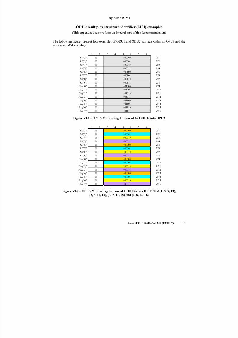
7/16/2019 G-709 ITU_T
http://slidepdf.com/reader/full/g-709-itut 195/218
Rec. ITU-T G.709/Y.1331 (12/2009) 187
Appendix VI
ODUk multiplex structure identifier (MSI) examples
(This appendix does not form an integral part of this Recommendation)
The following figures present four examples of ODU1 and ODU2 carriage within an OPU3 and theassociated MSI encoding.
1 2 3 4 5 6 7 8
PSI[ 2 ] 00 000000 TS 1
PSI[ 3 ] 00 000001 TS 2
PSI[ 4 ] 00 000010 TS 3
PSI[ 5 ] 00 000011 TS 4
PSI[ 6 ] 00 000100 TS 5
PSI[ 7 ] 00 000101 TS 6
PSI[ 8 ] 00 000110 TS 7
PSI[ 9 ] 00 000111 TS 8
PSI[ 10 ] 00 001000 TS 9
PSI[ 11 ] 00 001001 TS 10
PSI[ 12 ] 00 001010 TS 11
PSI[ 13 ] 00 001011 TS 12
PSI[ 14 ] 00 001100 TS 13
PSI[ 15 ] 00 001101 TS 14
PSI[ 16 ] 00 001110 TS 15
PSI[ 17 ] 00 001111 TS 16
Figure VI.1 – OPU3-MSI coding for case of 16 ODU1s into OPU3
1 2 3 4 5 6 7 8
PSI[ 2 ] 01 000000 TS 1
PSI[ 3 ] 01 000001 TS 2
PSI[ 4 ] 01 000010 TS 3
PSI[ 5 ] 01 000011 TS 4
PSI[ 6 ] 01 000000 TS 5
PSI[ 7 ] 01 000001 TS 6
PSI[ 8 ] 01 000010 TS 7
PSI[ 9 ] 01 000011 TS 8
PSI[ 10 ] 01 000000 TS 9
PSI[ 11 ] 01 000001 TS 10
PSI[ 12 ] 01 000010 TS 11
PSI[ 13 ] 01 000011 TS 12
PSI[ 14 ] 01 000000 TS 13
PSI[ 15 ] 01 000001 TS 14
PSI[ 16 ] 01 000010 TS 15
PSI[ 17 ] 01 000011 TS 16
Figure VI.2 – OPU3-MSI coding for case of 4 ODU2s into OPU3 TS# (1, 5, 9, 13),
(2, 6, 10, 14), (3, 7, 11, 15) and (4, 8, 12, 16)
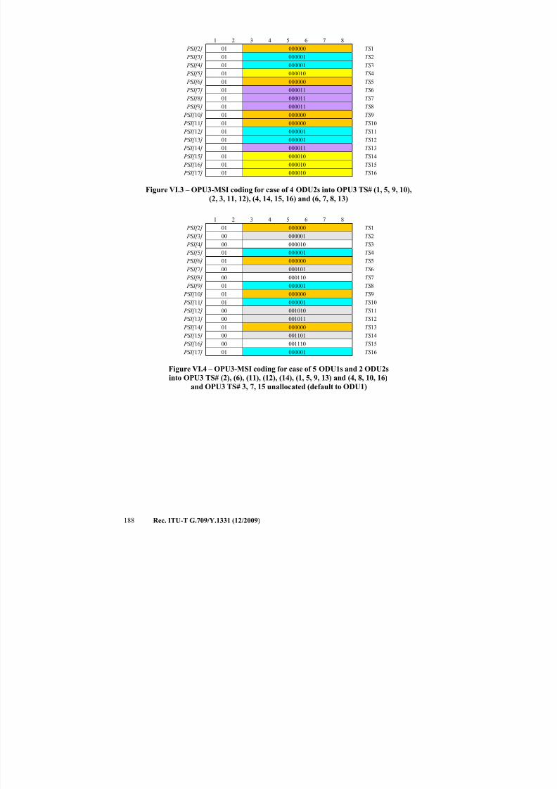
7/16/2019 G-709 ITU_T
http://slidepdf.com/reader/full/g-709-itut 196/218
188 Rec. ITU-T G.709/Y.1331 (12/2009)
1 2 3 4 5 6 7 8
PSI[ 2 ] 01 000000 TS 1
PSI[ 3 ] 01 000001 TS 2
PSI[ 4 ] 01 000001 TS 3
PSI[ 5 ] 01 000010 TS 4
PSI[ 6 ] 01 000000 TS 5
PSI[ 7 ] 01 000011 TS 6
PSI[ 8 ] 01 000011 TS 7
PSI[ 9 ] 01 000011 TS 8
PSI[ 10 ] 01 000000 TS 9
PSI[ 11 ] 01 000000 TS 10
PSI[ 12 ] 01 000001 TS 11
PSI[ 13 ] 01 000001 TS 12
PSI[ 14 ] 01 000011 TS 13
PSI[ 15 ] 01 000010 TS 14
PSI[ 16 ] 01 000010 TS 15
PSI[ 17 ] 01 000010 TS 16
Figure VI.3 – OPU3-MSI coding for case of 4 ODU2s into OPU3 TS# (1, 5, 9, 10),(2, 3, 11, 12), (4, 14, 15, 16) and (6, 7, 8, 13)
1 2 3 4 5 6 7 8
PSI[ 2 ] 01 000000 TS 1
PSI[ 3 ] 00 000001 TS 2
PSI[ 4 ] 00 000010 TS 3
PSI[ 5 ] 01 000001 TS 4
PSI[ 6 ] 01 000000 TS 5
PSI[ 7 ] 00 000101 TS 6
PSI[ 8 ] 00 000110 TS 7
PSI[ 9 ] 01 000001 TS 8 PSI[ 10 ] 01 000000 TS 9
PSI[ 11 ] 01 000001 TS 10
PSI[ 12 ] 00 001010 TS 11
PSI[ 13 ] 00 001011 TS 12
PSI[ 14 ] 01 000000 TS 13
PSI[ 15 ] 00 001101 TS 14
PSI[ 16 ] 00 001110 TS 15
PSI[ 17 ] 01 000001 TS 16
Figure VI.4 – OPU3-MSI coding for case of 5 ODU1s and 2 ODU2s
into OPU3 TS# (2), (6), (11), (12), (14), (1, 5, 9, 13) and (4, 8, 10, 16)
and OPU3 TS# 3, 7, 15 unallocated (default to ODU1)
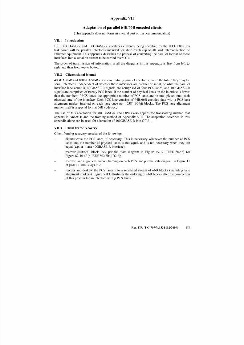
7/16/2019 G-709 ITU_T
http://slidepdf.com/reader/full/g-709-itut 197/218
Rec. ITU-T G.709/Y.1331 (12/2009) 189
Appendix VII
Adaptation of parallel 64B/66B encoded clients
(This appendix does not form an integral part of this Recommendation)
VII.1 IntroductionIEEE 40GBASE-R and 100GBASE-R interfaces currently being specified by the IEEE P802.3ba
task force will be parallel interfaces intended for short-reach (up to 40 km) interconnection of Ethernet equipment. This appendix describes the process of converting the parallel format of these
interfaces into a serial bit stream to be carried over OTN.
The order of transmission of information in all the diagrams in this appendix is first from left to
right and then from top to bottom.
VII.2 Clients signal format
40GBASE-R and 100GBASE-R clients are initially parallel interfaces, but in the future they may be
serial interfaces. Independent of whether these interfaces are parallel or serial, or what the parallelinterface lane count is, 40GBASE-R signals are comprised of four PCS lanes, and 100GBASE-R
signals are comprised of twenty PCS lanes. If the number of physical lanes on the interface is fewer than the number of PCS lanes, the appropriate number of PCS lanes are bit-multiplexed onto each
physical lane of the interface. Each PCS lane consists of 64B/66B encoded data with a PCS lanealignment marker inserted on each lane once per 16384 66-bit blocks. The PCS lane alignment
marker itself is a special format 66B codeword.
The use of this adaptation for 40GBASE-R into OPU3 also applies the transcoding method that
appears in Annex B and the framing method of Appendix VIII. The adaptation described in thisappendix alone can be used for adaptation of 100GBASE-R into OPU4.
VII.3 Client frame recovery
Client framing recovery consists of the following:
− disinterleave the PCS lanes, if necessary. This is necessary whenever the number of PCSlanes and the number of physical lanes is not equal, and is not necessary when they areequal (e.g., a 4-lane 40GBASE-R interface);
− recover 64B/66B block lock per the state diagram in Figure 49-12 [IEEE 802.3] (or
Figure 82-10 of [b-IEEE 802.3ba] D2.2);
− recover lane alignment marker framing on each PCS lane per the state diagram in Figure 11
of [b-IEEE 802.3ba] D2.2;
− reorder and deskew the PCS lanes into a serialized stream of 66B blocks (including lane
alignment markers). Figure VII.1 illustrates the ordering of 66B blocks after the completion
of this process for an interface with p PCS lanes.
7/16/2019 G-709 ITU_T
http://slidepdf.com/reader/full/g-709-itut 198/218
190 Rec. ITU-T G.709/Y.1331 (12/2009)
Figure VII.1 – Deskewed/serialized stream of 66B blocks
Each 66B codeword is one of the following:
− a set of eight data bytes with a sync header of "01";
− a control block (possibly including seven or fewer data octets) beginning with a syncheader of "10";
− a PCS lane alignment marker, also encoded with a sync header of "10". Of the 8 octetsfollowing the sync header, 6 octets have fixed values allowing the lane alignment markers
to be recognized (see Tables VII.1 and VII.2). The fourth octet following the sync header is
a BIP-8 calculated over the data from one alignment marker to the next. The eighth octet isthe complement of this BIP-8 value to maintain DC balance. Note that these BIP-8 values
are not manipulated by the mapping or demapping procedure, but simply skipped in the process of recognizing lane alignment markers and copied intact as they are used for
monitoring the error ratio of the Ethernet link between Ethernet PCS sublayers.
For all-data blocks and control blocks, the 64 bits following the sync header are scrambled as acontinuous bit-stream (skipping sync headers and PCS lane alignment markers) according to the
polynomial G( x) = 1 + x39
+ x58
.
After 64B/66B block lock recovery per the state diagram in Figure 49-12 of [IEEE 802.3] (or Figure 82-10 of [b-IEEE 802.3ba] D2.2), these 66B blocks are re-distributed to PCS lanes at the
egress interface. The 66B blocks (including PCS lane alignment markers) resulting from thedecoding process are distributed round-robin to PCS lanes. If the number of PCS lanes is greater than the number of physical lanes of the egress interface, the appropriate numbers of PCS lanes are
bit-multiplexed onto the physical lanes of the egress interface.
VII.3.1 40GBASE-R client frame recovery
PCS lane alignment markers have the values shown in Table VII.1 for 40GBASE-R signals whichuse PCS lane numbers 0-3. Note that these values will need to be aligned with the published
IEEE 802.3ba amendment once it is approved.
Lane Marker 1Lane Marker 2
:
Lane Marker p
p x 16383
66B blocks
Lane Marker 1Lane Marker 2
:Lane Marker p
p x 16383
66B blocks
1
2
p p +1
p x 16384
:
Transmission order
Transmission order
Lane Marker 1Lane Marker 2
:
Lane Marker p
p x 16383
66B blocks
Lane Marker 1Lane Marker 2
:Lane Marker p
p x 16383
66B blocks
Lane Marker 1Lane Marker 2
:
Lane Marker p
p x 16383
66B blocks
Lane Marker 1Lane Marker 2
:
Lane Marker p
Lane Marker 1Lane Marker 2Lane Marker 1Lane Marker 2
:
Lane Marker p
:
Lane Marker p
p x 16383
66B blocks
Lane Marker 1Lane Marker 2
:Lane Marker p
p x 16383
66B blocks
Lane Marker 1Lane Marker 2
:Lane Marker p
Lane Marker 1Lane Marker 2Lane Marker 1Lane Marker 2
:Lane Marker p
:Lane Marker p
p x 16383
66B blocks
1
2
p p +1
p x 16384
:
Transmission order
Transmission order
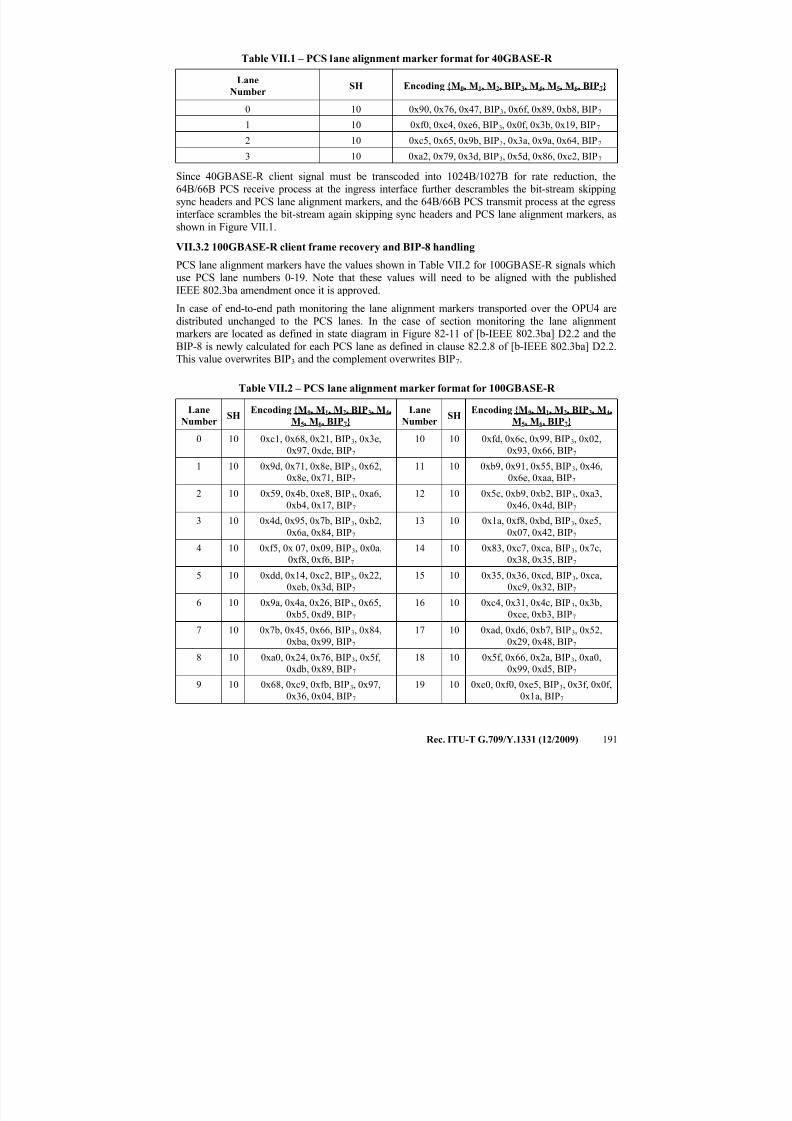
7/16/2019 G-709 ITU_T
http://slidepdf.com/reader/full/g-709-itut 199/218
Rec. ITU-T G.709/Y.1331 (12/2009) 191
Table VII.1 – PCS lane alignment marker format for 40GBASE-R
Lane
NumberSH Encoding {M0, M1, M2, BIP3, M4, M5, M6, BIP7}
0 10 0x90, 0x76, 0x47, BIP3, 0x6f, 0x89, 0xb8, BIP7
1 10 0xf0, 0xc4, 0xe6, BIP3, 0x0f, 0x3b, 0x19, BIP7
2 10 0xc5, 0x65, 0x9b, BIP3, 0x3a, 0x9a, 0x64, BIP7
3 10 0xa2, 0x79, 0x3d, BIP3, 0x5d, 0x86, 0xc2, BIP7
Since 40GBASE-R client signal must be transcoded into 1024B/1027B for rate reduction, the64B/66B PCS receive process at the ingress interface further descrambles the bit-stream skipping
sync headers and PCS lane alignment markers, and the 64B/66B PCS transmit process at the egressinterface scrambles the bit-stream again skipping sync headers and PCS lane alignment markers, as
shown in Figure VII.1.
VII.3.2 100GBASE-R client frame recovery and BIP-8 handling
PCS lane alignment markers have the values shown in Table VII.2 for 100GBASE-R signals whichuse PCS lane numbers 0-19. Note that these values will need to be aligned with the published
IEEE 802.3ba amendment once it is approved.
In case of end-to-end path monitoring the lane alignment markers transported over the OPU4 are
distributed unchanged to the PCS lanes. In the case of section monitoring the lane alignmentmarkers are located as defined in state diagram in Figure 82-11 of [b-IEEE 802.3ba] D2.2 and the
BIP-8 is newly calculated for each PCS lane as defined in clause 82.2.8 of [b-IEEE 802.3ba] D2.2.This value overwrites BIP3 and the complement overwrites BIP7.
Table VII.2 – PCS lane alignment marker format for 100GBASE-R
LaneNumber
SH Encoding {M0, M1, M2, BIP3, M4,M5, M6, BIP7}
LaneNumber
SH Encoding {M0, M1, M2, BIP3, M4,M5, M6, BIP7}
0 10 0xc1, 0x68, 0x21, BIP3, 0x3e,
0x97, 0xde, BIP7
10 10 0xfd, 0x6c, 0x99, BIP3, 0x02,
0x93, 0x66, BIP7
1 10 0x9d, 0x71, 0x8e, BIP3, 0x62,
0x8e, 0x71, BIP7
11 10 0xb9, 0x91, 0x55, BIP3, 0x46,
0x6e, 0xaa, BIP7
2 10 0x59, 0x4b, 0xe8, BIP3, 0xa6,
0xb4, 0x17, BIP7
12 10 0x5c, 0xb9, 0xb2, BIP3, 0xa3,
0x46, 0x4d, BIP7
3 10 0x4d, 0x95, 0x7b, BIP3, 0xb2,
0x6a, 0x84, BIP7
13 10 0x1a, 0xf8, 0xbd, BIP3, 0xe5,
0x07, 0x42, BIP7
4 10 0xf5, 0x 07, 0x09, BIP3, 0x0a,
0xf8, 0xf6, BIP7
14 10 0x83, 0xc7, 0xca, BIP3, 0x7c,
0x38, 0x35, BIP7
5 10 0xdd, 0x14, 0xc2, BIP3, 0x22,
0xeb, 0x3d, BIP7
15 10 0x35, 0x36, 0xcd, BIP3, 0xca,
0xc9, 0x32, BIP7
6 10 0x9a, 0x4a, 0x26, BIP3, 0x65,
0xb5, 0xd9, BIP7
16 10 0xc4, 0x31, 0x4c, BIP3, 0x3b,
0xce, 0xb3, BIP7
7 10 0x7b, 0x45, 0x66, BIP3, 0x84,
0xba, 0x99, BIP7
17 10 0xad, 0xd6, 0xb7, BIP3, 0x52,
0x29, 0x48, BIP7
8 10 0xa0, 0x24, 0x76, BIP3, 0x5f,
0xdb, 0x89, BIP7
18 10 0x5f, 0x66, 0x2a, BIP3, 0xa0,
0x99, 0xd5, BIP7
9 10 0x68, 0xc9, 0xfb, BIP3, 0x97,
0x36, 0x04, BIP7
19 10 0xc0, 0xf0, 0xe5, BIP3, 0x3f, 0x0f,
0x1a, BIP7
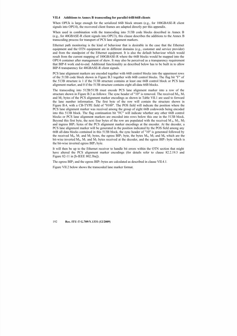
7/16/2019 G-709 ITU_T
http://slidepdf.com/reader/full/g-709-itut 200/218
192 Rec. ITU-T G.709/Y.1331 (12/2009)
VII.4 Additions to Annex B transcoding for parallel 64B/66B clients
When OPUk is large enough for the serialized 66B block stream (e.g., for 100GBASE-R client
signals into OPU4), the recovered client frames are adapted directly per this appendix.
When used in combination with the transcoding into 513B code blocks described in Annex B
(e.g., for 40GBASE-R client signals into OPU3), this clause describes the additions to the Annex B
transcoding process for transport of PCS lane alignment markers.Ethernet path monitoring is the kind of behaviour that is desirable in the case that the Ethernet
equipment and the OTN equipment are in different domains (e.g., customer and service provider)and from the standpoint of the Ethernet equipment. It is also the default behaviour which would
result from the current mapping of 100GBASE-R where the 66B blocks would be mapped into theOPU4 container after management of skew. It may also be perceived as a transparency requirement
that BIP-8 work end-to-end. Additional functionality as described below has to be built in to allowBIP-8 transparency for 40GBASE-R client signals.
PCS lane alignment markers are encoded together with 66B control blocks into the uppermost rowsof the 513B code block shown in Figure B.3 together with 66B control blocks. The flag bit "F" of
the 513B structure is 1 if the 513B structure contains at least one 66B control block or PCS lanealignment marker, and 0 if the 513B structure contains eight all-data 66B blocks.
The transcoding into 512B/513B must encode PCS lane alignment marker into a row of the
structure shown in Figure B.3 as follows: The sync header of "10" is removed. The received M0, M1 and M2 bytes of the PCS alignment marker encodings as shown in Table VII.1 are used to forward
the lane number information. The first byte of the row will contain the structure shown inFigure B.4, with a CB-TYPE field of "0100". The POS field will indicate the position where the
PCS lane alignment marker was received among the group of eight 66B codewords being encoded
into this 513B block. The flag continuation bit "FC" will indicate whether any other 66B control blocks or PCS lane alignment markers are encoded into rows below this one in the 513B block.
Beyond this first byte, the next four bytes of the row are populated with the received M0, M
1, M
2
and ingress BIP3 bytes of the PCS alignment marker encodings at the encoder. At the decoder, aPCS lane alignment marker will be generated in the position indicated by the POS field among any
66B all-data blocks contained in this 513B block, the sync header of "10" is generated followed by
the received M0, M1 and M2 bytes, the egress BIP3 byte, the bytes M4, M5 and M6 which are the bit-wise inverted M0, M1 and M2 bytes received at the decoder, and the egress BIP7 byte which is
the bit-wise inverted egress BIP3 byte.
It will then be up to the Ethernet receiver to handle bit errors within the OTN section that mighthave altered the PCS alignment marker encodings (for details refer to clause 82.2.19.3 and
Figure 82-11 in [b-IEEE 802.3ba]).
The egress BIP3 and the egress BIP7 bytes are calculated as described in clause VII.4.1.Figure VII.2 below shows the transcoded lane marker format.
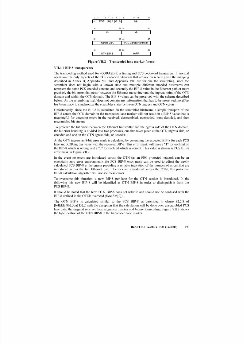
7/16/2019 G-709 ITU_T
http://slidepdf.com/reader/full/g-709-itut 201/218
Rec. ITU-T G.709/Y.1331 (12/2009) 193
Figure VII.2 – Transcoded lane marker format
VII.4.1 BIP-8 transparency
The transcoding method used for 40GBASE-R is timing and PCS codeword transparent. In normaloperation, the only aspects of the PCS encoded bitstream that are not preserved given the mapping
described in Annex B, Appendix VII, and Appendix VIII are for one the scrambling, since thescrambler does not begin with a known state and multiple different encoded bitstreams can
represent the same PCS encoded content, and secondly the BIP-8 value in the Ethernet path or more precisely the bit errors that occur between the Ethernet transmitter and the ingress point of the OTN
domain and within the OTN domain. The BIP-8 values can be preserved with the scheme described below. As the scrambling itself does not contain any information that has to be preserved, no effort
has been made to synchronize the scrambler states between OTN ingress and OTN egress.
Unfortunately, since the BIP-8 is calculated on the scrambled bitstream, a simple transport of the
BIP-8 across the OTN domain in the transcoded lane marker will not result in a BIP-8 value that ismeaningful for detecting errors in the received, descrambled, transcoded, trans-decoded, and then
rescrambled bit stream.
To preserve the bit errors between the Ethernet transmitter and the egress side of the OTN domain,the bit-error handling is divided into two processes, one that takes place at the OTN ingress side, or
encoder, and one on the OTN egress side, or decoder.
At the OTN ingress an 8-bit error mask is calculated by generating the expected BIP-8 for each PCSlane and XORing this value with the received BIP-8. This error mask will have a "1" for each bit of
the BIP-8 which is wrong, and a "0" for each bit which is correct. This value is shown as PCS BIP-8
error mask in Figure VII.2.
In the event no errors are introduced across the OTN (as an FEC protected network can be anessentially zero error environment), the PCS BIP-8 error mask can be used to adjust the newly
calculated PCS BIP-8 at the egress providing a reliable indication of the number of errors that areintroduced across the full Ethernet path. If errors are introduced across the OTN, this particular
BIP-8 calculation algorithm will not see these errors.
To overcome this situation, a new BIP-8 per lane for the OTN section is introduced. In thefollowing this new BIP-8 will be identified as OTN BIP-8 in order to distinguish it from the
PCS BIP-8.
It should be noted that the term OTN BIP-8 does not refer to and should not be confused with the
BIP-8 defined in the OTUk overhead (byte SM[2]).
The OTN BIP-8 is calculated similar to the PCS BIP-8 as described in clause 82.2.8 of
[b-IEEE 802.3ba] D2.2 with the exception that the calculation will be done over unscrambled PCS
lane data, the original received lane alignment marker and before transcoding. Figure VII.2 showsthe byte location of the OTN BIP-8 in the transcoded lane marker.
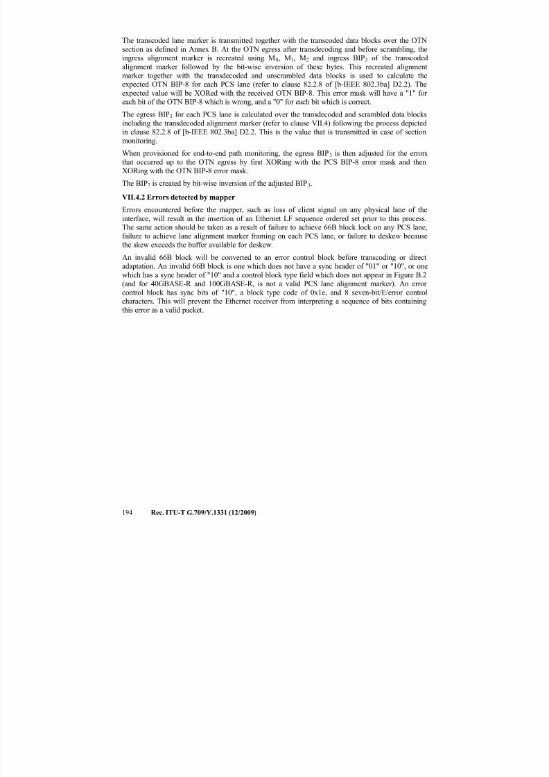
7/16/2019 G-709 ITU_T
http://slidepdf.com/reader/full/g-709-itut 202/218
194 Rec. ITU-T G.709/Y.1331 (12/2009)
The transcoded lane marker is transmitted together with the transcoded data blocks over the OTN
section as defined in Annex B. At the OTN egress after transdecoding and before scrambling, theingress alignment marker is recreated using M0, M1, M2 and ingress BIP3 of the transcoded
alignment marker followed by the bit-wise inversion of these bytes. This recreated alignment
marker together with the transdecoded and unscrambled data blocks is used to calculate theexpected OTN BIP-8 for each PCS lane (refer to clause 82.2.8 of [b-IEEE 802.3ba] D2.2). The
expected value will be XORed with the received OTN BIP-8. This error mask will have a "1" for each bit of the OTN BIP-8 which is wrong, and a "0" for each bit which is correct.
The egress BIP3 for each PCS lane is calculated over the transdecoded and scrambled data blocks
including the transdecoded alignment marker (refer to clause VII.4) following the process depictedin clause 82.2.8 of [b-IEEE 802.3ba] D2.2. This is the value that is transmitted in case of section
monitoring.
When provisioned for end-to-end path monitoring, the egress BIP3 is then adjusted for the errors
that occurred up to the OTN egress by first XORing with the PCS BIP-8 error mask and thenXORing with the OTN BIP-8 error mask.
The BIP7 is created by bit-wise inversion of the adjusted BIP3.
VII.4.2 Errors detected by mapper
Errors encountered before the mapper, such as loss of client signal on any physical lane of the
interface, will result in the insertion of an Ethernet LF sequence ordered set prior to this process.The same action should be taken as a result of failure to achieve 66B block lock on any PCS lane,
failure to achieve lane alignment marker framing on each PCS lane, or failure to deskew becausethe skew exceeds the buffer available for deskew.
An invalid 66B block will be converted to an error control block before transcoding or directadaptation. An invalid 66B block is one which does not have a sync header of "01" or "10", or one
which has a sync header of "10" and a control block type field which does not appear in Figure B.2
(and for 40GBASE-R and 100GBASE-R, is not a valid PCS lane alignment marker). An error control block has sync bits of "10", a block type code of 0x1e, and 8 seven-bit/E/error controlcharacters. This will prevent the Ethernet receiver from interpreting a sequence of bits containing
this error as a valid packet.
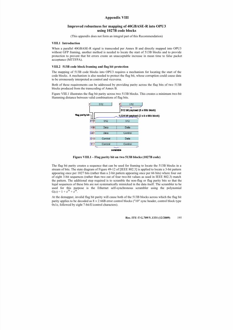
7/16/2019 G-709 ITU_T
http://slidepdf.com/reader/full/g-709-itut 203/218
Rec. ITU-T G.709/Y.1331 (12/2009) 195
Appendix VIII
Improved robustness for mapping of 40GBASE-R into OPU3
using 1027B code blocks
(This appendix does not form an integral part of this Recommendation)
VIII.1 Introduction
When a parallel 40GBASE-R signal is transcoded per Annex B and directly mapped into OPU3
without GFP framing, another method is needed to locate the start of 513B blocks and to provide
protection to prevent that bit errors create an unacceptable increase in mean time to false packet
acceptance (MTTFPA).
VIII.2 513B code block framing and flag bit protection
The mapping of 513B code blocks into OPU3 requires a mechanism for locating the start of the
code blocks. A mechanism is also needed to protect the flag bit, whose corruption could cause data
to be erroneously interpreted as control and viceversa.Both of these requirements can be addressed by providing parity across the flag bits of two 513B
blocks produced from the transcoding of Annex B.
Figure VIII.1 illustrates the flag bit parity across two 513B blocks. This creates a minimum two-bit
Hamming distance between valid combinations of flag bits.
Figure VIII.1 – Flag parity bit on two 513B blocks (1027B code)
The flag bit parity creates a sequence that can be used for framing to locate the 513B blocks in a
stream of bits. The state diagram of Figure 49-12 of [IEEE 802.3] is applied to locate a 3-bit pattern
appearing once per 1027 bits (rather than a 2-bit pattern appearing once per 66 bits) where four out
of eight 3-bit sequences (rather than two out of four two-bit values as used in IEEE 802.3) match
the pattern. The additional step required is to scramble the non-flag or flag parity bits so that the
legal sequences of these bits are not systematically mimicked in the data itself. The scrambler to be
used for this purpose is the Ethernet self-synchronous scrambler using the polynomial
G( x) = 1 + x39 + x
58.
At the demapper, invalid flag bit parity will cause both of the 513B blocks across which the flag bit
parity applies to be decoded as 8 × 2 66B error control blocks ("10" sync header, control block type0x1e, followed by eight 7-bit/E/control characters).
7/16/2019 G-709 ITU_T
http://slidepdf.com/reader/full/g-709-itut 204/218
196 Rec. ITU-T G.709/Y.1331 (12/2009)
VIII.3 66B block sequence check
Bit error corruption of the position or flag continuation bits could cause 66B blocks to be demapped
from 513B code blocks in the incorrect order. Additional checks are performed to prevent that this
results in incorrect packet delineation. Since detectable corruption normally means that the proper order of 66B blocks to construct at the decoder cannot be reliably determined, if any of these checks
fail, the decoder will transmit eight 66B error control blocks (sync="10", control block type=0x1e,
and eight 7-bit/E/control characters).
Other checks are performed to reduce the probability that invalid data is delivered at the egress in
the event that bit errors have corrupted any of the POS fields or flag continuation bits "FC".
If the Flag bit "F" is 1 (i.e., the 513B block includes at least one 64B/66B control block), for therows of the table up until the first one with a flag continuation bit of zero (the last one in the block),
it is verified that no two 66B control blocks or lane alignment markers within that 513B block havethe same value in the POS field, and further, that the POS field values for multiple control or lane
alignment rows are in ascending order, which will always be the case for a properly constructed
513B block. If this check fails, the 513B block is decoded into eight 66B error control blocks.
The next check is to ensure that the block sequence corresponds to well-formed packets, which can be done according to the state diagram in Figures VIII.2 and VIII.3. This check will determine if
66B blocks are in an order that does not correspond to well-formed packets, e.g., if during an IPGan all-data 66B block is detected without first seeing a control block representing packet start, or if
during a packet a control/idle block is detected without first seeing a control block representing packet termination, control blocks have likely been misordered by corruption of either the POS bits
or a flag continuation bit. Failure of this check will cause the 513B block to be decoded as eight
66B error control blocks. Note that PCS lane alignment markers are accepted in either state and donot change state as shown in Figure VIII.3.
The sequence of PCS lane alignment markers is also checked at the decoder. For an interface with p
PCS lanes, the PCS lane alignment markers for lanes 0 through p-1 will appear in a sequence,
followed by 16383× p non-lane-marker 66B blocks, followed by another group of PCS lane
alignment markers. A counter is maintained at the decoder to keep track of when the next group of lane alignment markers is expected. If, in the process of decoding lane alignment markers from a513B block, a lane alignment marker is found in a position where it is not expected, or a lane
alignment marker is missing in a position where it would have been expected, the entire 513B block is decoded as eight 66B error control blocks as shown in Figures VIII.2, VIII.3, and VIII.4.
VIII.3.1 State diagram conventions
The body of this clause is comprised of state diagrams, including the associated definitions of
variables, constants, and functions. Should there be a discrepancy between a state diagram and
descriptive text, the state diagram prevails.The notation used in the state diagrams follows the conventions of clause 21.5 of [IEEE 802.3].
State diagram timers follow the conventions of clause 14.2.3.2 of [IEEE 802.3]. The notation ++after a counter or integer variable indicates that its value is to be incremented.
VIII.3.2 State variables
VIII.3.2.1 Constants
EBLOCK_T<65:0>
66-bit vector to be sent to the PCS containing /E/ in all the eight character locations
Mi<65:0>
66-bit vector containing the transcoded alignment marker of i-th PCS lane (0 < i <= p).
( p=4 for 40GBASE-R, and p=20 for 100GBASE-R).
7/16/2019 G-709 ITU_T
http://slidepdf.com/reader/full/g-709-itut 205/218
Rec. ITU-T G.709/Y.1331 (12/2009) 197
VIII.3.2.2 Variables
1027B_block_lock
Indicates the state of the block_lock variable when the state diagram of Figure 49-12 of
[IEEE 802.3] is applied to locate a 3-bit pattern appearing once per 1027 bits (rather than a
2-bit pattern appearing once per 66 bits) as described in clause VIII.2. Set true when
sixty-four contiguous 1027-bit blocks are received with valid 3-bit patterns, set false whensixteen 1027-bit blocks with invalid 3-bit patterns are received before sixty-four valid blocks.
1027B_high_ber
Indicates Boolean variable when the state diagram of Figure 49-13 of [IEEE 802.3] is
applied to count invalid 3-bit sync headers of 1027-bit blocks (rather than 2-bit syncheaders of 66-bit blocks) within the current 250 μs (rather than 125 μs). Set true when the
ber_cnt exceeds 8 (rather than 16) indicating a bit error ratio >10 –4.
Mseq_violation
Indicates Boolean variable that is set and latched in each rx513_raw<527:0> PCS lanealignment marker cycle based on the PCS lane marker position and order. It is true if theunexpected marker sequence is detected and false if not.
POS_violation
Boolean variable that is set in each rx513_raw<527:0> based on the POS field values for
rx_tcd<65:0>. It is true if the two or more have the same POS values or if they are not inascending order, and false if their POS values are in ascending order.
reset
Boolean variable that controls the resetting of the PCS. It is true whenever a reset is
necessary including when reset is initiated from the MDIO, during power on, and when theMDIO has put the PCS into low-power mode.
Rx513_coded<512:0>
Vector containing the input to the 512B/513B decoder.
rx513_raw<527:0>
Vector containing eight successive 66-bit vectors (tx_coded)
rx_tcd<65:0>
66-bit vector transcode-decoded from a 513-bit block following the rules shown in
Figure B.5.
seq_violation
Boolean variable that is set in each rx513_raw<527:0> based on the sequence check on arx_tcd<65:0> stream. It is true if the unexpected sequence is detected and false if not.
VIII.3.2.3 Functions
DECODE(rx513_coded<512:0>)
Decodes the 513-bit vector returning rx513_raw<527 :0> which is sent to client interface.The DECODE function shall decode the block as specified in Figure VIII.2.
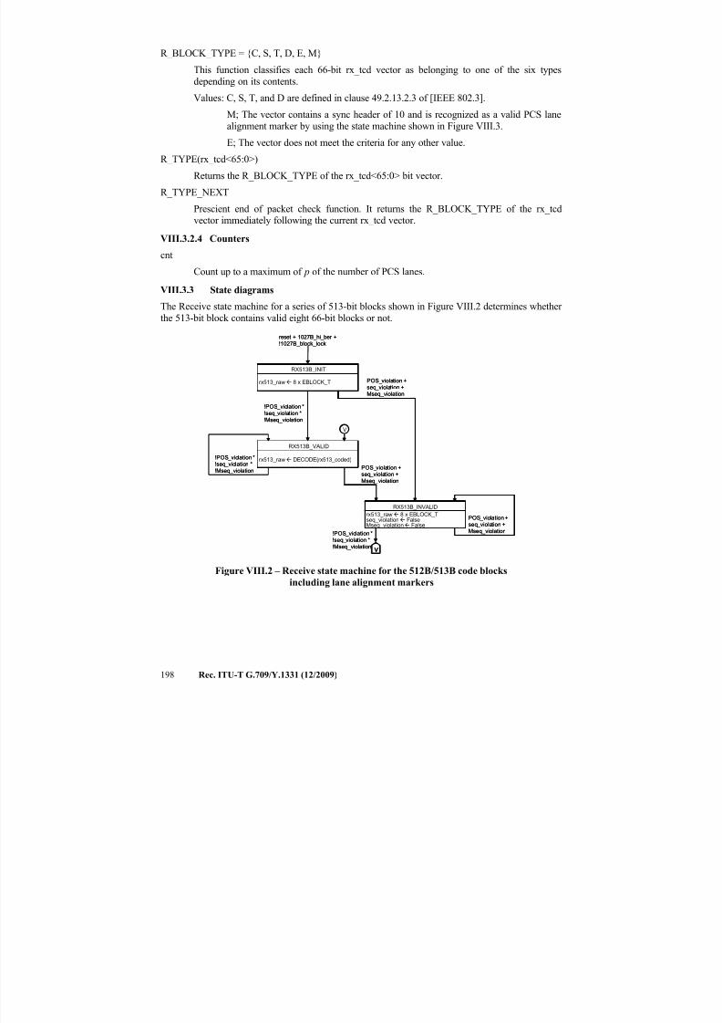
7/16/2019 G-709 ITU_T
http://slidepdf.com/reader/full/g-709-itut 206/218
198 Rec. ITU-T G.709/Y.1331 (12/2009)
R_BLOCK_TYPE = {C, S, T, D, E, M}
This function classifies each 66-bit rx_tcd vector as belonging to one of the six types
depending on its contents.
Values: C, S, T, and D are defined in clause 49.2.13.2.3 of [IEEE 802.3].
M; The vector contains a sync header of 10 and is recognized as a valid PCS lane
alignment marker by using the state machine shown in Figure VIII.3.
E; The vector does not meet the criteria for any other value.
R_TYPE(rx_tcd<65:0>)
Returns the R_BLOCK_TYPE of the rx_tcd<65:0> bit vector.
R_TYPE_NEXT
Prescient end of packet check function. It returns the R_BLOCK_TYPE of the rx_tcdvector immediately following the current rx_tcd vector.
VIII.3.2.4 Counters
cnt
Count up to a maximum of p of the number of PCS lanes.
VIII.3.3 State diagrams
The Receive state machine for a series of 513-bit blocks shown in Figure VIII.2 determines whether
the 513-bit block contains valid eight 66-bit blocks or not.
Figure VIII.2 – Receive state machine for the 512B/513B code blocks
including lane alignment markers
rx513_raw 8 x EBLOCK_T
RX513B_INIT
rx513_raw DECODE(rx513_coded)
RX513B_VALID
rx513_raw 8 x EBLOCK_Tseq_violation FalseMseq_violation False
RX513B_INVALID
V
V
!POS_violation *
!seq_violation *
!Mseq_violation
POS_violation +
seq_violation +
Mseq_violation
POS_violation +
seq_violation +
Mseq_violation
POS_violation+
seq_violation +
Mseq_violation
!POS_violation *
!seq_violation *
!Mseq_violation
!POS_violation *
!seq_violation *
!Mseq_violation
reset + 1027B_hi_ber +
!1027B_block_lock
rx513_raw 8 x EBLOCK_T
RX513B_INIT
rx513_raw 8 x EBLOCK_T
RX513B_INIT
rx513_raw DECODE(rx513_coded)
RX513B_VALID
rx513_raw DECODE(rx513_coded)
RX513B_VALID
rx513_raw 8 x EBLOCK_Tseq_violation FalseMseq_violation False
RX513B_INVALID
rx513_raw 8 x EBLOCK_Tseq_violation FalseMseq_violation False
RX513B_INVALID
VVV
VV
!POS_violation *
!seq_violation *
!Mseq_violation
POS_violation +
seq_violation +
Mseq_violation
POS_violation +
seq_violation +
Mseq_violation
POS_violation+
seq_violation +
Mseq_violation
!POS_violation *
!seq_violation *
!Mseq_violation
!POS_violation *
!seq_violation *
!Mseq_violation
reset + 1027B_hi_ber +
!1027B_block_lock
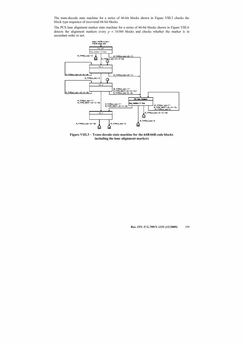
7/16/2019 G-709 ITU_T
http://slidepdf.com/reader/full/g-709-itut 207/218
Rec. ITU-T G.709/Y.1331 (12/2009) 199
The trans-decode state machine for a series of 66-bit blocks shown in Figure VIII.3 checks the
block type sequence of recovered 66-bit blocks.
The PCS lane alignment marker state machine for a series of 66-bit blocks shown in Figure VIII.4
detects the alignment markers every p × 16384 blocks and checks whether the marker is inascendant order or not.
Figure VIII.3 – Trans-decode state machine for the 64B/66B code blocks
including the lane alignment markers
Seq_violation False
RX_INIT
RX_C
RX_D
RX_T
Seq_violation True
RX_Seq_Violation
D
C
D
DD
C
C
R_TYPE(rx_tcd) = S
R_TYPE(rx_tcd) = (C + E + M)
R_TYPE(rx_tcd) = (D + E + M)
R_TYPE(rx_tcd) = (C + E + M)
R_TYPE(rx_tcd) = S
R_TYPE(rx_tcd) = T *
R_TYPE_NEXT = (S + C + M)
R_TYPE(rx_tcd) = (C + M) R_TYPE(rx_tcd) = S
R_TYPE(rx_tcd) = (C + E + M)
R_TYPE(rx_tcd) = D
R_TYPE(rx_tcd) = (D + T)
R_TYPE(rx_tcd) = (D + T)
(R_TYPE(rx_tcd) = T *
R_TYPE_NEXT = (E + D + T)) +
R_TYPE(rx_tcd) = (C + S)
(R_TYPE(rx_tcd) = T *
R_TYPE_NEXT = (E + D + T))
+ R_TYPE(rx_tcd) = S
R_TYPE(rx_tcd) = T *
R_TYPE_NEXT = (S + C + M)
reset + 1027B_hi_ber +!1027B_block_lock
Seq_violation False
RX_INIT
Seq_violation False
RX_INIT
RX_CRX_C
RX_DRX_D
RX_TRX_T
Seq_violation True
RX_Seq_Violation
Seq_violation True
RX_Seq_Violation
DD
CC
DDD
DDDD
CC
CC
R_TYPE(rx_tcd) = S
R_TYPE(rx_tcd) = (C + E + M)
R_TYPE(rx_tcd) = (D + E + M)
R_TYPE(rx_tcd) = (C + E + M)
R_TYPE(rx_tcd) = S
R_TYPE(rx_tcd) = T *
R_TYPE_NEXT = (S + C + M)
R_TYPE(rx_tcd) = (C + M) R_TYPE(rx_tcd) = S
R_TYPE(rx_tcd) = (C + E + M)
R_TYPE(rx_tcd) = D
R_TYPE(rx_tcd) = (D + T)
R_TYPE(rx_tcd) = (D + T)
(R_TYPE(rx_tcd) = T *
R_TYPE_NEXT = (E + D + T)) +
R_TYPE(rx_tcd) = (C + S)
(R_TYPE(rx_tcd) = T *
R_TYPE_NEXT = (E + D + T))
+ R_TYPE(rx_tcd) = S
R_TYPE(rx_tcd) = T *
R_TYPE_NEXT = (S + C + M)
reset + 1027B_hi_ber +!1027B_block_lock
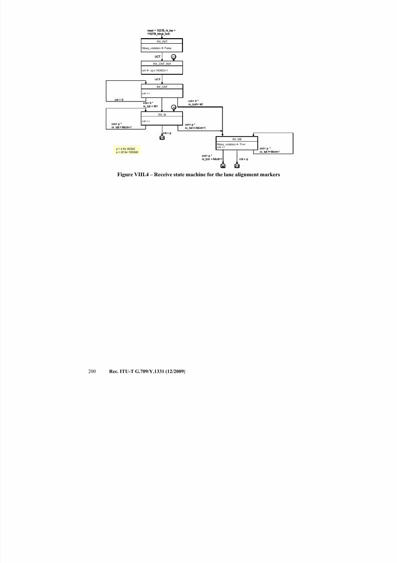
7/16/2019 G-709 ITU_T
http://slidepdf.com/reader/full/g-709-itut 208/218
200 Rec. ITU-T G.709/Y.1331 (12/2009)
Figure VIII.4 – Receive state machine for the lane alignment markers
cnt ++
RX_CNT
cnt ++
RX_M
Mseq_violation Truecnt ++
RX_ME
cnt< p *
rx_tcd = Mcnt+1
cnt= 0 *
rx_tcd!= M1
M
M CT
cnt < 0
cnt = p
CT
cnt = p
CT
Mseq_violation False
RX_INIT
reset + 1027B_hi_ber +
!1027B_block_lock
UCT
cnt -(p x 16383)+1
RX_CNT_INIT
cnt< p *
rx_tcd != Mcnt+1
cnt< p *
rx_tcd != Mcnt+1
cnt< p *
rx_tcd = Mcnt+1
p = 4 for 40GbE
p = 20 for 100GbE
cnt= 0 *
rx_tcd = M1
UCT
cnt ++
RX_CNT
cnt ++
RX_CNT
cnt ++
RX_M
cnt ++
RX_M
Mseq_violation Truecnt ++
RX_ME
Mseq_violation Truecnt ++
RX_ME
cnt< p *
rx_tcd = Mcnt+1
cnt= 0 *
rx_tcd!= M1
MM
MMM CTCT
cnt < 0
cnt = p
CTCT
cnt = p
CTCT
Mseq_violation False
RX_INIT
Mseq_violation False
RX_INIT
reset + 1027B_hi_ber +
!1027B_block_lock
UCT
cnt -(p x 16383)+1
RX_CNT_INIT
cnt -(p x 16383)+1
RX_CNT_INIT
cnt< p *
rx_tcd != Mcnt+1
cnt< p *
rx_tcd != Mcnt+1
cnt< p *
rx_tcd = Mcnt+1
p = 4 for 40GbE
p = 20 for 100GbE
cnt= 0 *
rx_tcd = M1
UCT
7/16/2019 G-709 ITU_T
http://slidepdf.com/reader/full/g-709-itut 209/218
Rec. ITU-T G.709/Y.1331 (12/2009) 201
Appendix IX
Parallel logic implementation of the CRC-8 and CRC-5
(This appendix does not form an integral part of this Recommendation)
CRC-8
Table IX.1 illustrates example logic equations for a parallel implementation of the CRC-8 using theg(x) = x8 + x3 + x2 + 1 polynomial over the JC1-JC2. An "X" in a row of the table indicates that the
message bit of that column is an input to the Exclusive-OR equation for calculating the CRC bit of
that row. JC1.C1 corresponds to the first bit (MSB) of the first mapping overhead octet (JC1);JC1.C2 corresponds to bit 2 of the first mapping overhead octet, etc. After computation, CRC bits
crc1 to crc8 are inserted into the JC3 octet with crc1 occupying MSB and crc8 the LSB of the octet.
Table IX.1 – Parallel logic equations for the CRC-8 implementation
Mapping
overhead bits
CRC checksum bits
crc1 crc2 crc3 crc4 crc5 crc6 crc7 crc8
JC1.C1 X X X
JC1.C2 X X X
JC1.C3 X X X
JC1.C4 X X X
JC1.C5 X X X
JC1.C6 X X X
JC1.C7 X X X
JC1.C8 X X XJC2.C9 X X X X X
JC2.C10 X X X X X
JC2.C11 X X X X X
JC2.C12 X X X
JC2.C13 X X X
JC2.C14 X X X
JC2.II X X X
JC2.DI X X X
CRC-5
Table IX.2 illustrates example logic equations for a parallel implementation of the CRC-5 using theg(x) = x5 + x + 1 polynomial over the JC4-JC5 CnD fields. An "X" in a row of the table indicates
that the message bit of that column is an input to the Exclusive-OR equation for calculating theCRC bit of that row. JC4.D1 corresponds to the first bit (MSB) of the first mapping overhead octet
(JC1); JC4.D2 corresponds to bit 2 of the first mapping overhead octet, etc. After computation,
CRC bits crc1 to crc5 are inserted into the JC6 octet with crc1 occupying JC6 bit 4 and crc5 the JC6 bit 8.

7/16/2019 G-709 ITU_T
http://slidepdf.com/reader/full/g-709-itut 210/218
202 Rec. ITU-T G.709/Y.1331 (12/2009)
Table IX.2 – Parallel logic equations for the CRC-5 implementation
Mapping
overhead bits
CRC checksum bits
crc1 crc2 crc3 crc4 crc5
JC4.D1 X X X
JC4.D2 X X XJC4.D3 X X
JC4.D4 X X
JC4.D5 X X
JC5.D6 X X X
JC5.D7 X X
JC5.D8 X X
JC5.D9 X X
JC5.D10 X X
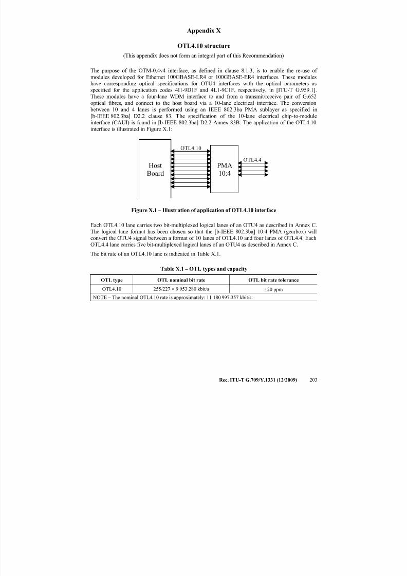
7/16/2019 G-709 ITU_T
http://slidepdf.com/reader/full/g-709-itut 211/218
Rec. ITU-T G.709/Y.1331 (12/2009) 203
Appendix X
OTL4.10 structure
(This appendix does not form an integral part of this Recommendation)
The purpose of the OTM-0.4v4 interface, as defined in clause 8.1.3, is to enable the re-use of modules developed for Ethernet 100GBASE-LR4 or 100GBASE-ER4 interfaces. These modules
have corresponding optical specifications for OTU4 interfaces with the optical parameters asspecified for the application codes 4I1-9D1F and 4L1-9C1F, respectively, in [ITU-T G.959.1].
These modules have a four-lane WDM interface to and from a transmit/receive pair of G.652
optical fibres, and connect to the host board via a 10-lane electrical interface. The conversion between 10 and 4 lanes is performed using an IEEE 802.3ba PMA sublayer as specified in
[b-IEEE 802.3ba] D2.2 clause 83. The specification of the 10-lane electrical chip-to-moduleinterface (CAUI) is found in [b-IEEE 802.3ba] D2.2 Annex 83B. The application of the OTL4.10
interface is illustrated in Figure X.1:
HostBoard
PMA10:4
OTL4.10
OTL4.4
Figure X.1 – Illustration of application of OTL4.10 interface
Each OTL4.10 lane carries two bit-multiplexed logical lanes of an OTU4 as described in Annex C.
The logical lane format has been chosen so that the [b-IEEE 802.3ba] 10:4 PMA (gearbox) willconvert the OTU4 signal between a format of 10 lanes of OTL4.10 and four lanes of OTL4.4. Each
OTL4.4 lane carries five bit-multiplexed logical lanes of an OTU4 as described in Annex C.
The bit rate of an OTL4.10 lane is indicated in Table X.1.
Table X.1 – OTL types and capacity
OTL type OTL nominal bit rate OTL bit rate tolerance
OTL4.10 255/227 × 9 953 280 kbit/s ±20 ppm
NOTE – The nominal OTL4.10 rate is approximately: 11 180 997.357 kbit/s.
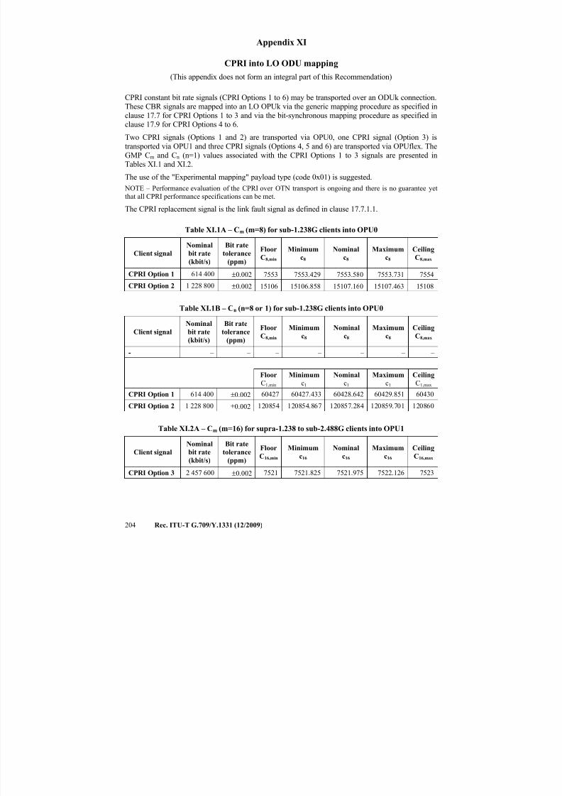
7/16/2019 G-709 ITU_T
http://slidepdf.com/reader/full/g-709-itut 212/218
204 Rec. ITU-T G.709/Y.1331 (12/2009)
Appendix XI
CPRI into LO ODU mapping
(This appendix does not form an integral part of this Recommendation)
CPRI constant bit rate signals (CPRI Options 1 to 6) may be transported over an ODUk connection.These CBR signals are mapped into an LO OPUk via the generic mapping procedure as specified in
clause 17.7 for CPRI Options 1 to 3 and via the bit-synchronous mapping procedure as specified inclause 17.9 for CPRI Options 4 to 6.
Two CPRI signals (Options 1 and 2) are transported via OPU0, one CPRI signal (Option 3) is
transported via OPU1 and three CPRI signals (Options 4, 5 and 6) are transported via OPUflex. The
GMP Cm and Cn (n=1) values associated with the CPRI Options 1 to 3 signals are presented inTables XI.1 and XI.2.
The use of the "Experimental mapping" payload type (code 0x01) is suggested.
NOTE – Performance evaluation of the CPRI over OTN transport is ongoing and there is no guarantee yet
that all CPRI performance specifications can be met.
The CPRI replacement signal is the link fault signal as defined in clause 17.7.1.1.
Table XI.1A – Cm (m=8) for sub-1.238G clients into OPU0
Client signal
Nominal
bit rate
(kbit/s)
Bit rate
tolerance
(ppm)
Floor
C8,min
Minimum
c8
Nominal
c8
Maximum
c8
Ceiling
C8,max
CPRI Option 1 614 400 ±0.002 7553 7553.429 7553.580 7553.731 7554
CPRI Option 2 1 228 800±0.002 15106 15106.858 15107.160 15107.463 15108
Table XI.1B – Cn (n=8 or 1) for sub-1.238G clients into OPU0
Client signal
Nominal
bit rate
(kbit/s)
Bit rate
tolerance
(ppm)
Floor
C8,min
Minimum
c8
Nominal
c8
Maximum
c8
Ceiling
C8,max
- – – – – – – –
Floor
C1,min
Minimum
c1
Nominal
c1
Maximum
c1
Ceiling
C1,max CPRI Option 1 614 400 ±0.002 60427 60427.433 60428.642 60429.851 60430
CPRI Option 2 1 228 800 ±0.002 120854 120854.867 120857.284 120859.701 120860
Table XI.2A – Cm (m=16) for supra-1.238 to sub-2.488G clients into OPU1
Client signal
Nominal
bit rate
(kbit/s)
Bit rate
tolerance
(ppm)
Floor
C16,min
Minimum
c16
Nominal
c16
Maximum
c16
Ceiling
C16,max
CPRI Option 3 2 457 600 ±0.002 7521 7521.825 7521.975 7522.126 7523
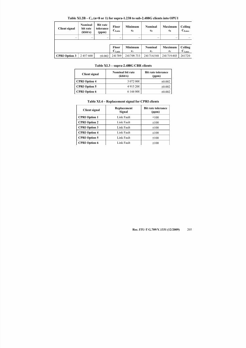
7/16/2019 G-709 ITU_T
http://slidepdf.com/reader/full/g-709-itut 213/218
Rec. ITU-T G.709/Y.1331 (12/2009) 205
Table XI.2B – Cn (n=8 or 1) for supra-1.238 to sub-2.488G clients into OPU1
Client signal
Nominal
bit rate
(kbit/s)
Bit rate
tolerance
(ppm)
Floor
C8,min
Minimum
c8
Nominal
c8
Maximum
c8
Ceiling
C8,max
– – – – – – – –
Floor
C1,min
Minimum
c1
Nominal
c1
Maximum
c1
Ceiling
C1,max
CPRI Option 3 2 457 600 ±0.002 241709 241709.733 241714.568 241719.403 241720
Table XI.3 – supra-2.488G CBR clients
Client signalNominal bit rate
(kbit/s)
Bit rate tolerance
(ppm)
CPRI Option 4 3 072 000 ±0.002
CPRI Option 5 4 915 200 ±0.002
CPRI Option 6 6 144 000 ±0.002
Table XI.4 – Replacement signal for CPRI clients
Client signalReplacement
Signal
Bit rate tolerance
(ppm)
CPRI Option 1 Link Fault ±100
CPRI Option 2 Link Fault ±100
CPRI Option 3 Link Fault ±100
CPRI Option 4 Link Fault ±100
CPRI Option 5 Link Fault ±100
CPRI Option 6 Link Fault ±100
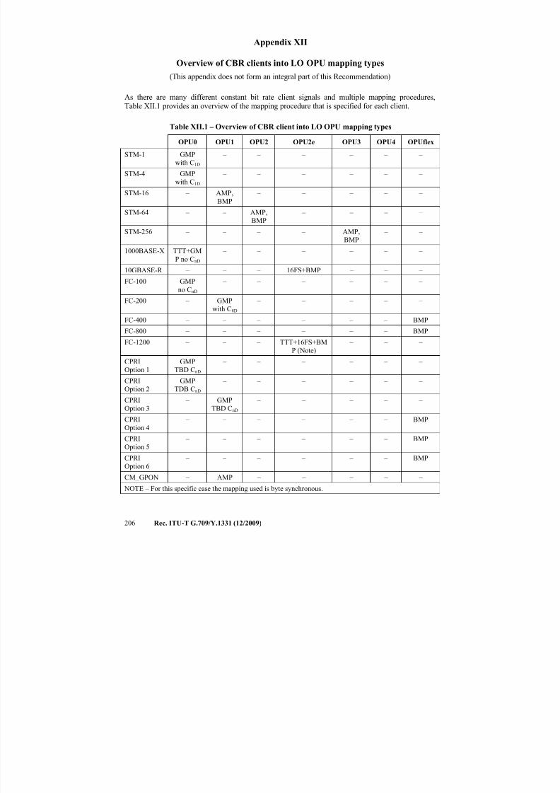
7/16/2019 G-709 ITU_T
http://slidepdf.com/reader/full/g-709-itut 214/218
206 Rec. ITU-T G.709/Y.1331 (12/2009)
Appendix XII
Overview of CBR clients into LO OPU mapping types
(This appendix does not form an integral part of this Recommendation)
As there are many different constant bit rate client signals and multiple mapping procedures,Table XII.1 provides an overview of the mapping procedure that is specified for each client.
Table XII.1 – Overview of CBR client into LO OPU mapping types
OPU0 OPU1 OPU2 OPU2e OPU3 OPU4 OPUflex
STM-1 GMP
with C1D
– – – – – –
STM-4 GMP
with C1D
– – – – – –
STM-16 – AMP,BMP
– – – – –
STM-64 – – AMP,
BMP
– – – –
STM-256 – – – – AMP,
BMP
– –
1000BASE-X TTT+GM
P no CnD
– – – – – –
10GBASE-R – – – 16FS+BMP – – –
FC-100 GMP
no CnD
– – – – – –
FC-200 – GMP
with C8D
– – – – –
FC-400 – – – – – – BMP
FC-800 – – – – – – BMP
FC-1200 – – – TTT+16FS+BM
P (Note)
– – –
CPRI
Option 1
GMP
TBD CnD
– – – – – –
CPRI
Option 2
GMP
TDB CnD
– – – – – –
CPRI
Option 3
– GMP
TBD CnD
– – – – –
CPRI
Option 4
– – – – – – BMP
CPRI
Option 5
– – – – – – BMP
CPRI
Option 6
– – – – – – BMP
CM_GPON – AMP – – – – –
NOTE – For this specific case the mapping used is byte synchronous.

7/16/2019 G-709 ITU_T
http://slidepdf.com/reader/full/g-709-itut 215/218
Rec. ITU-T G.709/Y.1331 (12/2009) 207
Bibliography
[b-ANSI INCITS 364] ANSI INCITS 364-2003, Information Technology – Fibre Channel to gigabit (10GFC).
[b-IEEE 802.3ba] IEEE 802.3 ba , 40 Gb/s and 100 Gb/s Ethernet TaskForce.

7/16/2019 G-709 ITU_T
http://slidepdf.com/reader/full/g-709-itut 216/218
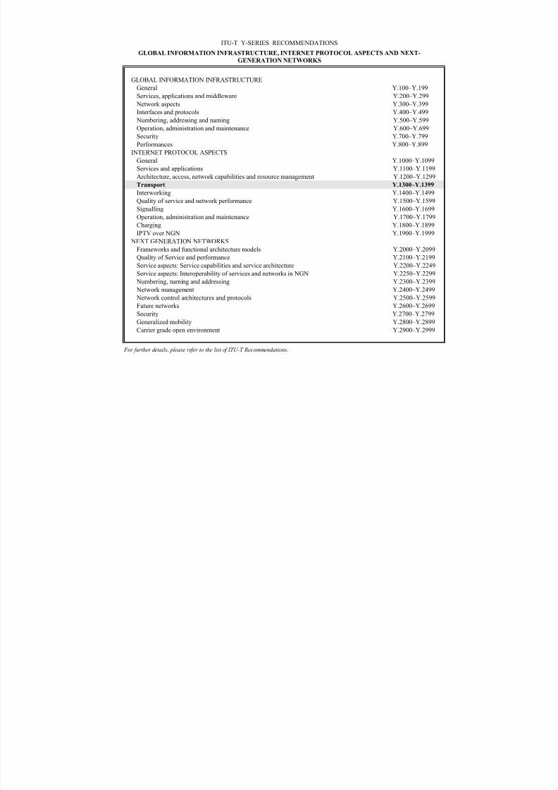
7/16/2019 G-709 ITU_T
http://slidepdf.com/reader/full/g-709-itut 217/218
ITU-T Y-SERIES RECOMMENDATIONS
GLOBAL INFORMATION INFRASTRUCTURE, INTERNET PROTOCOL ASPECTS AND NEXT-
GENERATION NETWORKS
GLOBAL INFORMATION INFRASTRUCTURE
General Y.100–Y.199
Services, applications and middleware Y.200–Y.299 Network aspects Y.300–Y.399
Interfaces and protocols Y.400–Y.499
Numbering, addressing and naming Y.500–Y.599
Operation, administration and maintenance Y.600–Y.699
Security Y.700–Y.799
Performances Y.800–Y.899
INTERNET PROTOCOL ASPECTS
General Y.1000–Y.1099
Services and applications Y.1100–Y.1199
Architecture, access, network capabilities and resource management Y.1200–Y.1299
Transport Y.1300–Y.1399
Interworking Y.1400–Y.1499Quality of service and network performance Y.1500–Y.1599
Signalling Y.1600–Y.1699
Operation, administration and maintenance Y.1700–Y.1799
Charging Y.1800–Y.1899
IPTV over NGN Y.1900–Y.1999
NEXT GENERATION NETWORKS
Frameworks and functional architecture models Y.2000–Y.2099
Quality of Service and performance Y.2100–Y.2199
Service aspects: Service capabilities and service architecture Y.2200–Y.2249
Service aspects: Interoperability of services and networks in NGN Y.2250–Y.2299
Numbering, naming and addressing Y.2300–Y.2399
Network management Y.2400–Y.2499
Network control architectures and protocols Y.2500–Y.2599
Future networks Y.2600–Y.2699
Security Y.2700–Y.2799
Generalized mobility Y.2800–Y.2899
Carrier grade open environment Y.2900–Y.2999
For further details, please refer to the list of ITU-T Recommendations.
7/16/2019 G-709 ITU_T
http://slidepdf.com/reader/full/g-709-itut 218/218
SERIES OF ITU-T RECOMMENDATIONS
Series A Organization of the work of ITU-T
Series D General tariff principles
Series E Overall network operation, telephone service, service operation and human factors
Series F Non-telephone telecommunication services
Series G Transmission systems and media, digital systems and networks
Series H Audiovisual and multimedia systems
Series I Integrated services digital network