g-brake lights: an adaptive rear lighting system based on ... · december 2010 doc id 18011 rev 2...
TRANSCRIPT
December 2010 Doc ID 18011 Rev 2 1/27
AN3288Application note
g-Brake Lights: an adaptive rear lighting system based on theAIS326DQ inertial sensor and the STM8AF5168 MCU
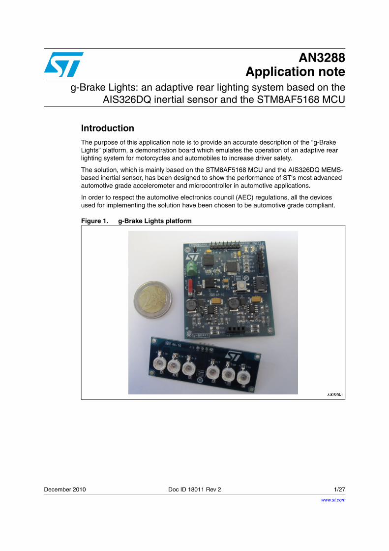
IntroductionThe purpose of this application note is to provide an accurate description of the “g-Brake Lights” platform, a demonstration board which emulates the operation of an adaptive rear lighting system for motorcycles and automobiles to increase driver safety.
The solution, which is mainly based on the STM8AF5168 MCU and the AIS326DQ MEMS-based inertial sensor, has been designed to show the performance of ST's most advanced automotive grade accelerometer and microcontroller in automotive applications.
In order to respect the automotive electronics council (AEC) regulations, all the devices used for implementing the solution have been chosen to be automotive grade compliant.
Figure 1. g-Brake Lights platform
www.st.com

Contents AN3288
2/27 Doc ID 18011 Rev 2
Contents
1 Scope of the platform . . . . . . . . . . . . . . . . . . . . . . . . . . . . . . . . . . . . . . . . 4
1.1 Key features . . . . . . . . . . . . . . . . . . . . . . . . . . . . . . . . . . . . . . . . . . . . . . . . 4
2 System architecture . . . . . . . . . . . . . . . . . . . . . . . . . . . . . . . . . . . . . . . . . 5
2.1 System description . . . . . . . . . . . . . . . . . . . . . . . . . . . . . . . . . . . . . . . . . . . 5
2.2 Block diagram . . . . . . . . . . . . . . . . . . . . . . . . . . . . . . . . . . . . . . . . . . . . . . . 5
2.3 Data measuring and elaborating . . . . . . . . . . . . . . . . . . . . . . . . . . . . . . . . 6
2.4 HB-LED array driving . . . . . . . . . . . . . . . . . . . . . . . . . . . . . . . . . . . . . . . . . 7
3 Firmware design . . . . . . . . . . . . . . . . . . . . . . . . . . . . . . . . . . . . . . . . . . . 10
3.1 State machine . . . . . . . . . . . . . . . . . . . . . . . . . . . . . . . . . . . . . . . . . . . . . 10
3.2 Digital filtering . . . . . . . . . . . . . . . . . . . . . . . . . . . . . . . . . . . . . . . . . . . . . . 11
3.3 Thresholds system . . . . . . . . . . . . . . . . . . . . . . . . . . . . . . . . . . . . . . . . . . 13
4 Special features . . . . . . . . . . . . . . . . . . . . . . . . . . . . . . . . . . . . . . . . . . . . 15
4.1 Bidirectional functionality . . . . . . . . . . . . . . . . . . . . . . . . . . . . . . . . . . . . . 15
4.2 Continuous dimming mode . . . . . . . . . . . . . . . . . . . . . . . . . . . . . . . . . . . . 18
4.3 Adaptability to other applications . . . . . . . . . . . . . . . . . . . . . . . . . . . . . . . 19
5 Schematics and bill of material . . . . . . . . . . . . . . . . . . . . . . . . . . . . . . . 20
6 Revision history . . . . . . . . . . . . . . . . . . . . . . . . . . . . . . . . . . . . . . . . . . . 26
AN3288 List of figures
Doc ID 18011 Rev 2 3/27
List of figures
Figure 1. g-Brake Lights platform. . . . . . . . . . . . . . . . . . . . . . . . . . . . . . . . . . . . . . . . . . . . . . . . . . . . . 1Figure 2. g-Brake Lights block diagram . . . . . . . . . . . . . . . . . . . . . . . . . . . . . . . . . . . . . . . . . . . . . . . . 6Figure 3. Buck converter schematic based on A5970AD . . . . . . . . . . . . . . . . . . . . . . . . . . . . . . . . . . 7Figure 4. PWM signal with duty cycle of 100 % . . . . . . . . . . . . . . . . . . . . . . . . . . . . . . . . . . . . . . . . . . 8Figure 5. PWM signal with duty cycle of 65 % . . . . . . . . . . . . . . . . . . . . . . . . . . . . . . . . . . . . . . . . . . . 8Figure 6. PWM signal with duty cycle of 50 % . . . . . . . . . . . . . . . . . . . . . . . . . . . . . . . . . . . . . . . . . . . 9Figure 7. PWM signal with duty cycle of 25 % . . . . . . . . . . . . . . . . . . . . . . . . . . . . . . . . . . . . . . . . . . . 9Figure 8. State machine block diagram . . . . . . . . . . . . . . . . . . . . . . . . . . . . . . . . . . . . . . . . . . . . . . . 10Figure 9. Acceleration raw data and moving average filtered data . . . . . . . . . . . . . . . . . . . . . . . . . . 12Figure 10. Thresholds system diagram . . . . . . . . . . . . . . . . . . . . . . . . . . . . . . . . . . . . . . . . . . . . . . . . 13Figure 11. Direction recognition based on filtered data . . . . . . . . . . . . . . . . . . . . . . . . . . . . . . . . . . . . 15Figure 12. Direction-defining state machine block diagram . . . . . . . . . . . . . . . . . . . . . . . . . . . . . . . . . 16Figure 13. STM8A microcontroller . . . . . . . . . . . . . . . . . . . . . . . . . . . . . . . . . . . . . . . . . . . . . . . . . . . . 20Figure 14. Accelerometer AIS326DQ . . . . . . . . . . . . . . . . . . . . . . . . . . . . . . . . . . . . . . . . . . . . . . . . . 21Figure 15. Microcontroller power supply, LIN - UART, user LEDS, spare pins, test points . . . . . . . . . 22Figure 16. Buck converter for HB-LED driving. . . . . . . . . . . . . . . . . . . . . . . . . . . . . . . . . . . . . . . . . . . 23

Scope of the platform AN3288
4/27 Doc ID 18011 Rev 2
1 Scope of the platform
The “g-Brake Lights” platform is an add-on brake lamp useful as an additional warning light to increase safety in motorbike use, but just a few changes enable it to be used in other kinds of vehicles. This solution is capable of increasing vehicle safety levels especially in situations requiring a fast braking light response. In fact, the light intensity of the brake light can be adapted to the braking intensity.
Moreover, compared to traditional incandescent bulb solutions, the main advantages of this platform are:
● the very short switch-on time
● the low power consumption due to low power devices and the efficient conversion of electrical power into optical power
● the high lifetime of the optical actuator (for optimized LEDs, up to 100.000 hours)
A brief overview of the g-Brake Lights main blocks and characteristics follows.
1.1 Key featuresThe main features are:
● Operations independent of the braking system
● Variable light intensities proportional to vehicle decelerations
● More than 1,000 programmable levels of brightness based on decelerations
● Six 1 W-Power LED light source outputs
● Real-time light response
● Self-calibrating bidirectional functionality; automatically identifies the direction of movement
● 12 V battery operating
● LIN-UART peripherals networking capability

AN3288 System architecture
Doc ID 18011 Rev 2 5/27
2 System architecture
The main block of the g-Brake Lights platform is made up of the ST MCU STM8AF5168, the ST MEMS-based inertial sensor AIS326DQ, and step-down switching regulator A5970AD; its task is to continuously acquire data, elaborate them distinguishing the several phases of motion, and actuate a proper light response to warn of the braking phase.
The basic functioning of the system is presented in the following paragraphs.
2.1 System descriptionThe g-Brake Lights platform provides an optical representation of the deceleration detected by the accelerometer AIS326DQ during the braking phase of a vehicle; the light intensity of the brake lamp, implemented by the two high brightness LED arrays (each of them is made up of three high brightness LEDs connected in series), varies according to the braking intensity of the vehicle. The aim is to make the driver's intentions more visible, in order to provide the following drivers with faster reaction times.
The board has been designed to acquire the acceleration/deceleration data continuously and independently from the vehicle's braking circuit. This allows an autonomous system with a fast real-time response to be had. The response time mainly depends on the data elaboration made by the STM8A microcontroller after the acquisition.
A digital low-pass filter has been implemented to reduce noise corruption during the data collecting; this noise is the result of a vehicle's high frequency vibrations due to the engine and the road. The filtered signal is more intelligible and its representation fits with the real behavior of the vehicle. A mechanical isolation could also be applied, even though it is not strictly necessary, to further filter the noise.
Finally, a combination of dynamic thresholds enable the variation of light intensity. The deceleration data, after filtering, are continuously compared with specific ranges of values in order to discriminate, case by case, the braking forces of the vehicle. The two arrays of HB-LEDs are used as actuators in order to maximize the visibility of the warning and reduce the turn-on and turn-off time to a minimum.
2.2 Block diagramThe core of the g-Brake Lights solution is made up of the ST MCU STM8AF5168, the ST MEMS-based inertial sensor AIS326DQ, and two buck converters using the ST step-down switching regulators A5970AD for LED driving.
Basically, the MCU continuously elaborates the information provided by the accelerometer and generates a PWM signal for driving the two buck converters connected to the two HB-LED arrays. The MCU varies the PWM signal duty cycle, depending on the braking effects, on the basis of a set of thresholds. So, the brightness of the two HB-LED arrays is directly proportional to the detected deceleration on the basis of the variation of the PWM signal duty cycle.
The HB-LED arrays have been mounted on the secondary board in order to have a separation between the sensing block and the light actuator, and, at the same time, a more flexible mechanical system for assembling on the test vehicle.

System architecture AN3288
6/27 Doc ID 18011 Rev 2
The system is 12 V battery operated in order to be compliant with automotive target specifics, but can be easily modified to work at lower voltages; all the devices forming the data sensing and elaboration block are supplied to 3.3 V by the ST LF33CDT voltage regulator. The block diagram of the system is shown in Figure 2.
Figure 2. g-Brake Lights block diagram
2.3 Data measuring and elaboratingDevice selection has been made considering firstly the impact of the performances on the system efficiency, and their compatibility with automotive regulations.
The platform is mainly based on a continuous data acquisition performed by the accelerometer and the data elaboration and interpretation made by the MCU. Each phase has been optimized to be executed in the shortest time and to reduce the introduction of vibrational noise to a minimum.
Regarding the platform core, the main devices are the MCU and the accelerometer; the MCU is the automotive 8-bit STM8AF5168, with the core working at 16 MHz (up to 24 MHz with external clock), Flash memory up to 128 Kbytes, and an extensive range of enhanced I/Os and peripherals including I2C, SPI, LIN, CAN, and USART. The low-g accelerometer is the AIS326DQ, it is automotive-qualified and offers 12-bit resolution, full-scale range of +/- 2g or +/- 6g in all three axes, wide temperature range from -40 to +105 °C, and high shock survivability up to 10,000 g for 0.1 ms, 3.3 V single-supply operation, 1.8 V-compatible I/Os, and an SPI/I2C serial digital output supporting direct connection to a microcontroller.
To maximize the execution rate, the STM8AF5168 MCU system clock has been set to the maximum speed with the internal clock (16 MHz) and the data transmission between MCU and the accelerometer AIS326DQ is performed by the SPI peripheral which enables the hi-speed data transmission.
It is fundamental to remove vibrational noise in order to improve system reliability. All the oscillation caused by the road and the engine are not filtered by the mechanical dampers, as the vibrational noise could overlap the useful signal (deceleration), modulating it to high frequency. To discriminate the deceleration signal from the modulated one, it's appropriate to filter the high frequency components; the implementation of a software filter (Section 3.2) reduces the noise component in the signal and avoids further mechanical considerations for dampening the oscillations on the vehicle structure.

AN3288 System architecture
Doc ID 18011 Rev 2 7/27
2.4 HB-LED array drivingAfter the signal elaboration, the MCU opportunely drives the two buck converters, based on the A5970AD regulators, to obtain a proper light brightness proportional to the effort of the measured deceleration. The A5970AD is a step-down monolithic power switching regulator for automotive applications qualified to AEC-Q100 requirements, with a minimum switch current limit of 1.35 A to the load depending on application conditions, and an operating input voltage from 4 V to 36 V.
The MCU digitally controls the dimming of the two LED arrays, applying a square wave with variable duty cycle (pulse-width modulation or PWM) to the LED driving circuit. In order to drive its switching, the STM8AF5168 MCU is directly connected to the INHIBIT pins of the two A5970AD regulators.
Using pulse-width modulation (PWM) to set the period and duty cycle is the easiest way to accomplish the digital dimming, and the buck regulator topology provides the best driving performance for this application.
Figure 3. Buck converter schematic based on A5970AD
The LEDs switching frequency must be faster than the human eye can detect in order to avoid a flickering effect (about 200 Hz or faster is usually acceptable). To obtain the best light efficiency from the 2 HB-LED arrays and to optimize their dimming, the MCU generates a PWM signal with a frequency fixed to 300 Hz, while the duty cycle changes its value with the variation of the deceleration detected by the AIS326DQ. This configuration allows LEDs to switch between ON and OFF as quick as possible, allowing the system to have a fast response and a low power consumption.
In order to identify four different kinds of light actuations corresponding to the different deceleration ranges, a system of four main functional thresholds has been set in the firmware. So the four major ranges of braking effort have been correlated to four fixed values of duty cycle:
● for no braking, duty cycle = 100 %
● for soft braking, duty cycle = 65 %
● for medium braking, duty cycle = 50 %
● for strong braking, duty cycle = 25 %

System architecture AN3288
8/27 Doc ID 18011 Rev 2
These thresholds set the levels of the current that flows in each HB-LED array. As shown in Figure 4, 5, 6, and 7, the current average value in each HB-LED array varies from zero, when duty cycle = 100 %, to 250 mA when braking is at its maximum. So the LEDs are OFF for most of the time, while during the braking phase the LED light intensity varies with the duty cycle, proportional to the braking effort.
Note: The user may add more thresholds in order to have soft dimming.
Figure 4. PWM signal with duty cycle of 100 %
Figure 5. PWM signal with duty cycle of 65 %

AN3288 System architecture
Doc ID 18011 Rev 2 9/27
Figure 6. PWM signal with duty cycle of 50 %
Figure 7. PWM signal with duty cycle of 25 %

Firmware design AN3288
10/27 Doc ID 18011 Rev 2
3 Firmware design
Once the system architecture is defined, firmware implementation is fundamental because the MCU controls the several devices and manages the resource optimization; the MCU sets the system clock and enables the SPI peripheral for the data transferring with the accelerometer. The choice of a state machine has allowed the three main process steps (acquisition, elaboration, and actuation) to be put into three states, making the algorithm more flexible and easy to manage.
The algorithm designed for controlling the system and the data elaboration and light actuation during braking is described in the following paragraphs.
3.1 State machineThe state machine organizes the operations which take place in this application. It has been designed as event-driven systems based on three main states called ACQUIRE, PROCESS, and ACTUATE. At any given time, the application exists in one of these three states.
The block diagram of the designed state machine is shown in Figure 8.
Figure 8. State machine block diagram
After the system initialization, the algorithm uses polling within a loop to determine when to read data. In the first state (ACQUIRE), the data acquisition is performed by the MCU which continuously receives data from the accelerometer and puts them in a buffer. In the PROCESS state, first the MCU elaborates data, filtering them from high frequency noise caused by mechanical vibrations (see Section 3.2), and then compares the filtered values with a thresholds equation system to determinate the effort of the braking.
Finally, in the ACTUATE state, the MCU performs the light actuation. As anticipated, the system is event-driven but the MCU executes the third state only if the deceleration value is higher than the activation level; this is a useful solution in order to avoid accidental actuation due to harsh road conditions.
AN3288 Firmware design
Doc ID 18011 Rev 2 11/27
During the last state, the MCU varies the PWM signal duty cycle only once the event occurs (braking effort higher than activation level), and the detected deceleration value is higher than the activation threshold and bounded in a threshold range (see Section 3.3).
The state machine timing has a fundamental importance for synchronizing the data acquisition from the accelerometer with the data elaboration process. In fact, the state machine clock has been tailored to acquire a new value, calculate the average with the previous deceleration values and actuate the light response, all in the same clock cycle. As the time between two subsequent acquisitions represents a limiting condition for the clock setting, the state machine clock rate is fixed to 40 Hz by the accelerometer acquisition rate. Starting from this assumption, the clock rate has been fixed to come to an arrangement between the MCU performances and the acquisition rate, considering that for a higher sensor output data rate there is a higher noise introduced in the system.
3.2 Digital filteringAs anticipated, the filtering process is necessary to clean the deceleration signal captured by the accelerometer AIS326DQ and overlapped to the vibrational noise produced by the oscillations of a vehicle's mechanical parts. The choice of a suitable digital filter has been made considering also that it inserts latency in the data elaboration process and this latency depends on the complexity level of the filter.
A moving (running)-average filter is optimal for this task, mainly for its simplicity to be implemented and integrated in the data processing flow; the latency of this filter is relatively low in comparison with other FIR filters, and depends on the samples number to be averaged out. Before designing the filter, it's important to have a complete modeling of the vehicle’s dynamic characteristics to understand how the noise affects the acceleration signal and identify the right number of samples for processing.
After a preliminary analysis on the test vehicle characteristics, a moving (running)-average filter able to elaborate 10 samples per cycle has been designed. For each cycle, it computes the average value in an array of 10 elements, subtracting the maximum and the minimum values.
for( k=0; k<10; ++k)
{
if(k!=9)
Sample_Vector[k] = Sample_Vector[k+1];
else
{
...
/* when new data available, copying in the buffer vector */
Sample_Vector[9] = AIS326DQ_Read_1Axis(OUTX_L);
}
subtotal += Sample_Vector[k];
/* calculation of the max and the min in the buffer vector */
if( Sample_Vector[k] < min ) min = Sample_Vector[k];
Firmware design AN3288
12/27 Doc ID 18011 Rev 2
if( Sample_Vector[k] > max ) max = Sample_Vector[k];
}
/* calculation of the moving average value */
mov_avg = ((subtotal - min - max)/8);
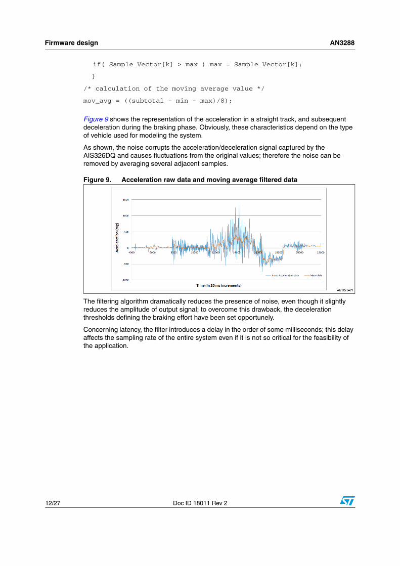
Figure 9 shows the representation of the acceleration in a straight track, and subsequent deceleration during the braking phase. Obviously, these characteristics depend on the type of vehicle used for modeling the system.
As shown, the noise corrupts the acceleration/deceleration signal captured by the AIS326DQ and causes fluctuations from the original values; therefore the noise can be removed by averaging several adjacent samples.
Figure 9. Acceleration raw data and moving average filtered data
The filtering algorithm dramatically reduces the presence of noise, even though it slightly reduces the amplitude of output signal; to overcome this drawback, the deceleration thresholds defining the braking effort have been set opportunely.
Concerning latency, the filter introduces a delay in the order of some milliseconds; this delay affects the sampling rate of the entire system even if it is not so critical for the feasibility of the application.
AN3288 Firmware design
Doc ID 18011 Rev 2 13/27
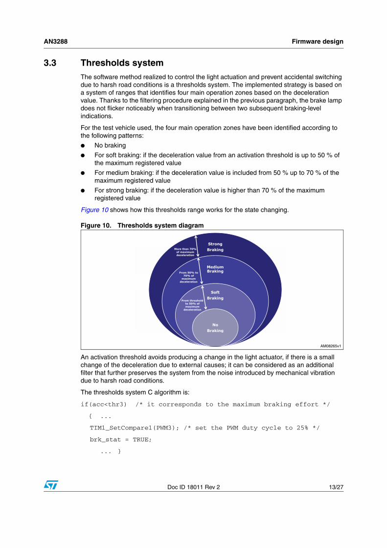
3.3 Thresholds systemThe software method realized to control the light actuation and prevent accidental switching due to harsh road conditions is a thresholds system. The implemented strategy is based on a system of ranges that identifies four main operation zones based on the deceleration value. Thanks to the filtering procedure explained in the previous paragraph, the brake lamp does not flicker noticeably when transitioning between two subsequent braking-level indications.
For the test vehicle used, the four main operation zones have been identified according to the following patterns:
● No braking
● For soft braking: if the deceleration value from an activation threshold is up to 50 % of the maximum registered value
● For medium braking: if the deceleration value is included from 50 % up to 70 % of the maximum registered value
● For strong braking: if the deceleration value is higher than 70 % of the maximum registered value
Figure 10 shows how this thresholds range works for the state changing.
Figure 10. Thresholds system diagram
An activation threshold avoids producing a change in the light actuator, if there is a small change of the deceleration due to external causes; it can be considered as an additional filter that further preserves the system from the noise introduced by mechanical vibration due to harsh road conditions.
The thresholds system C algorithm is:
if(acc<thr3) /* it corresponds to the maximum braking effort */
{ ...
TIM1_SetCompare1(PWM3); /* set the PWM duty cycle to 25% */
brk_stat = TRUE;
... }
Firmware design AN3288
14/27 Doc ID 18011 Rev 2
else if(acc<thr2) /* it corresponds to a medium braking effort */
{...
TIM1_SetCompare1(PWM2); /* set the PWM duty cycle to 50% */
brk_stat = TRUE;
... }
else if(acc<thr1) /* it corresponds to a soft braking effort */
{...
TIM1_SetCompare1(PWM1); /* set the PWM duty cycle to 75% */
brk_stat = TRUE;
... }
else /* if no braking */
{TIM1_SetCompare1(PWM0); /* PWM duty cycle to 100% set LEDs OFF */
brk_stat = FALSE; }
For each deceleration range, the MCU sets the PWM signal duty cycle in order to switch LEDs ON when a braking occurs, and then an internal timer starts to manage the light duration.
AN3288 Special features
Doc ID 18011 Rev 2 15/27
4 Special features
The following is a brief overview of the g-Brake Lights special features, which allows the platform to be adapted to automobiles, general transportation systems, and other vehicles.
4.1 Bidirectional functionalityThe designed platform is mainly optimized for non-reversing vehicles such as motorcycles. To adapt the platform function to automobiles, it is necessary to modify the previous state machine (Figure 8), introducing the capability of distinguishing the braking phase also when the vehicle is in reverse.
Once the position of the accelerometer on the vehicle and the orientation of its main axis are defined, it's useful to observe how the acceleration signal varies on the basis of the movement direction.
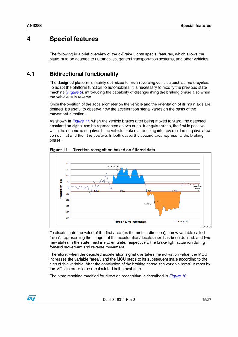
As shown in Figure 11, when the vehicle brakes after being moved forward, the detected acceleration signal can be represented as two quasi-triangular areas, the first is positive while the second is negative. If the vehicle brakes after going into reverse, the negative area comes first and then the positive. In both cases the second area represents the braking phase.
Figure 11. Direction recognition based on filtered data
To discriminate the value of the first area (as the motion direction), a new variable called “area”, representing the integral of the acceleration/deceleration has been defined, and two new states in the state machine to emulate, respectively, the brake light actuation during forward movement and reverse movement.
Therefore, when the detected acceleration signal overtakes the activation value, the MCU increases the variable “area”, and the MCU steps to its subsequent state according to the sign of this variable. After the conclusion of the braking phase, the variable “area” is reset by the MCU in order to be recalculated in the next step.
The state machine modified for direction recognition is described in Figure 12.

Special features AN3288
16/27 Doc ID 18011 Rev 2
Figure 12. Direction-defining state machine block diagram
The following is the code enabling this feature:
/* the direction identification algorithm starts above and below the activation thresholds */
if((acc< activ_neg)||(acc> activ_pos))
{
area += (acc);
/* defining of 2 saturation values (positive and negative) */
if(area>satur_pos) area= satur_pos;
else if(area<satur_neg) area= satur_neg;
}
if(area>0)
/* if area >0 --> "FORWARD" direction */
state = ACTUATE_FORWARD;
else if(area<0)
/* if area <0 --> "REVERSE" direction */
state = ACTUATE_REVERSE;
else
state = WAIT;

AN3288 Special features
Doc ID 18011 Rev 2 17/27
Regarding the two new states, while “ACTUATE_FORWARD” is implemented as the state previously reported in the previous thresholds system C algorithm, the state “ACTUATE_REVERSE” has been implemented in the same way but with positive threshold values.
The thresholds system code modified for enabling the bidirectional functionality is represented here:
/* "FORWARD" direction */
state ACTUATE_FORWARD:
if(acc<thr3a) /* it corresponds to the maximum braking effort */
{ ...
TIM1_SetCompare1(PWM3); /* set the PWM duty cycle to 25% */
brk_stat = TRUE;
... }
else if(acc<thr2a) /* it corresponds to a medium braking effort */
{...
TIM1_SetCompare1(PWM2); /* set the PWM duty cycle to 50% */
brk_stat = TRUE;
... }
...
else /* if no braking */
{TIM1_SetCompare1(PWM0); /* PWM duty cycle to 100% set LEDs OFF */
brk_stat = FALSE; }
state= WAIT;
break;
/*****************************************************************/
/* "REVERSE" direction */
state ACTUATE_REVERSE:
if(acc>thr3b) /* it corresponds to the maximum braking effort */
{ ...
TIM1_SetCompare1(PWM3); /* set the PWM duty cycle to 25% */
Special features AN3288
18/27 Doc ID 18011 Rev 2
brk_stat = TRUE;
... }
else if(acc>thr2b) /* it corresponds to a medium braking effort */
{...
TIM1_SetCompare1(PWM2); /* set the PWM duty cycle to 50% */
brk_stat = TRUE;
... }
...
else /* if no braking */
{TIM1_SetCompare1(PWM0); /* PWM duty cycle to 100% set LEDs OFF */
brk_stat = FALSE; }
state= WAIT;
break;
4.2 Continuous dimming modeThe choice of the main ranges of deceleration for characterizing the light response is purely discretionary. It's possible to set a continuous dimming mode matching the LEDs’ brightness with the resolution of the accelerometer. Fixing a simple relation of proportionality between the PWM duty cycle and the deceleration, according to a coefficient opportunely selected, the LED’s brightness may vary continuously in a range of values containing more than 1,000 programmable levels.
/* PWM duty cycle proportional to the deceleration */
PWM_duty_cycle=(acc*(k));
...
if(acc< thr1) /* if deceleration is higher than the activation threshold */
{ ...
TIM1_SetCompare1(PWM_duty_cycle); /* set the PWM duty cycle */
brk_stat = TRUE; }
...}
AN3288 Special features
Doc ID 18011 Rev 2 19/27
else /* if no braking */
{TIM1_SetCompare1(PWM0); /* PWM duty cycle to 100% set LEDs OFF */
brk_stat = FALSE; }
4.3 Adaptability to other applicationsThe designed platform is mainly optimized for motorcycles but its functions can be easily adapted to other applications such as bicycles, two or four wheel electric vehicles, or radio controlled toys in general, by changing the devices in non automotive grade and setting the thresholds opportunely.
AN
3288S
chem
atics and
bill o
f material
Doc ID
18011 Rev 2
20/27
5 Schematics and bill of material
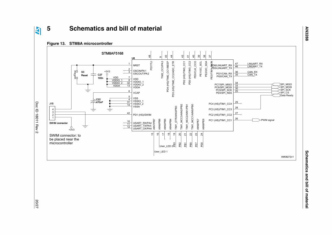
Figure 13. STM8A microcontroller

AN3288 Schematics and bill of material
Doc ID 18011 Rev 2 21/27
Figure 14. Accelerometer AIS326DQ

Schematics and bill of material AN3288
22/27 Doc ID 18011 Rev 2
Figure 15. Microcontroller power supply, LIN - UART, user LEDS, spare pins, test points

AN3288 Schematics and bill of material
Doc ID 18011 Rev 2 23/27
Figure 16. Buck converter for HB-LED driving
AN
3288S
chem
atics and
bill o
f material
Doc ID
18011 Rev 2
24/27
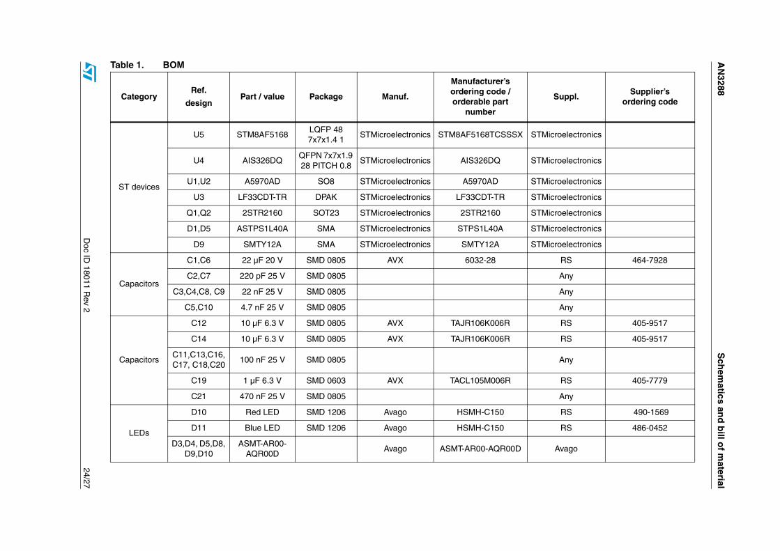
Table 1. BOM
CategoryRef.
designPart / value Package Manuf.
Manufacturer’s ordering code / orderable part
number
Suppl.Supplier’s
ordering code
ST devices
U5 STM8AF5168LQFP 48 7x7x1.4 1
STMicroelectronics STM8AF5168TCSSSX STMicroelectronics
U4 AIS326DQQFPN 7x7x1.9 28 PITCH 0.8
STMicroelectronics AIS326DQ STMicroelectronics
U1,U2 A5970AD SO8 STMicroelectronics A5970AD STMicroelectronics
U3 LF33CDT-TR DPAK STMicroelectronics LF33CDT-TR STMicroelectronics
Q1,Q2 2STR2160 SOT23 STMicroelectronics 2STR2160 STMicroelectronics
D1,D5 ASTPS1L40A SMA STMicroelectronics STPS1L40A STMicroelectronics
D9 SMTY12A SMA STMicroelectronics SMTY12A STMicroelectronics
Capacitors
C1,C6 22 µF 20 V SMD 0805 AVX 6032-28 RS 464-7928
C2,C7 220 pF 25 V SMD 0805 Any
C3,C4,C8, C9 22 nF 25 V SMD 0805 Any
C5,C10 4.7 nF 25 V SMD 0805 Any
Capacitors
C12 10 µF 6.3 V SMD 0805 AVX TAJR106K006R RS 405-9517
C14 10 µF 6.3 V SMD 0805 AVX TAJR106K006R RS 405-9517
C11,C13,C16, C17, C18,C20
100 nF 25 V SMD 0805 Any
C19 1 µF 6.3 V SMD 0603 AVX TACL105M006R RS 405-7779
C21 470 nF 25 V SMD 0805 Any
LEDs
D10 Red LED SMD 1206 Avago HSMH-C150 RS 490-1569
D11 Blue LED SMD 1206 Avago HSMH-C150 RS 486-0452
D3,D4, D5,D8, D9,D10
ASMT-AR00-AQR00D
Avago ASMT-AR00-AQR00D Avago

Sch
ematics an
d b
ill of m
aterialA
N3288
25/27D
oc ID 18011 R
ev 2
Connectors
J3Battery
connectorMORS2_S PHOENIX Contact 1725656 RS 220-4260
J6 CON6Strip line male
2.54 mmAny Any
Connectors
J7SWIM
connectorCONNECT_S
WIMERNI 214012 RS 247-600
J8 CON8Strip line male
2.54 mmAny Any
J9, J10 CON1TESTPOINT_
SKeystone Electr. Digi-Key 5001K-ND
J11 CON4Strip line
female 2.54 mm
Any
Inductor L1,L2 82 µH Ind308_1235 Sumida CDRH6D28-820NC Digi-Key 308-1235-1-ND
Resistors
RS1,RS2 1.5 Ω 1% 1/4 W SMD 1206 Any
RS3,RS4 1 Ω 1% 1/4 W SMD 1206 Any
R1,R5 2.7 kΩ 1/8 W SMD 0805 Any
R2,R6 4.7 kΩ 1/8 W SMD 0805 Any
R3,R7 240 kΩ 1/8 W SMD 1206 Any
R4,R8 1.3 kΩ 1/8 W SMD 0805 Any
Resistors R9,R10 180 Ω SMD 0805 Any
Misc.S1 Power switch
THR (spacing 2.54 mm)
EAO 09 03290 01 RS 204-7865
S2 Reset PULS4SMD. Tyco RS 479-1508
Table 1. BOM (continued)
CategoryRef.
designPart / value Package Manuf.
Manufacturer’s ordering code / orderable part
number
Suppl.Supplier’s
ordering code

Revision history AN3288
26/27 Doc ID 18011 Rev 2
6 Revision history
Table 2. Document revision history
Date Revision Changes
04-Oct-2010 1 Initial release.
13-Dec-2010 2– Changed: Table 1: BOM– Changed: Figure 1: g-Brake Lights platform

AN3288
Doc ID 18011 Rev 2 27/27
Please Read Carefully:
Information in this document is provided solely in connection with ST products. STMicroelectronics NV and its subsidiaries (“ST”) reserve theright to make changes, corrections, modifications or improvements, to this document, and the products and services described herein at anytime, without notice.
All ST products are sold pursuant to ST’s terms and conditions of sale.
Purchasers are solely responsible for the choice, selection and use of the ST products and services described herein, and ST assumes noliability whatsoever relating to the choice, selection or use of the ST products and services described herein.
No license, express or implied, by estoppel or otherwise, to any intellectual property rights is granted under this document. If any part of thisdocument refers to any third party products or services it shall not be deemed a license grant by ST for the use of such third party productsor services, or any intellectual property contained therein or considered as a warranty covering the use in any manner whatsoever of suchthird party products or services or any intellectual property contained therein.
UNLESS OTHERWISE SET FORTH IN ST’S TERMS AND CONDITIONS OF SALE ST DISCLAIMS ANY EXPRESS OR IMPLIEDWARRANTY WITH RESPECT TO THE USE AND/OR SALE OF ST PRODUCTS INCLUDING WITHOUT LIMITATION IMPLIEDWARRANTIES OF MERCHANTABILITY, FITNESS FOR A PARTICULAR PURPOSE (AND THEIR EQUIVALENTS UNDER THE LAWSOF ANY JURISDICTION), OR INFRINGEMENT OF ANY PATENT, COPYRIGHT OR OTHER INTELLECTUAL PROPERTY RIGHT.
UNLESS EXPRESSLY APPROVED IN WRITING BY AN AUTHORIZED ST REPRESENTATIVE, ST PRODUCTS ARE NOTRECOMMENDED, AUTHORIZED OR WARRANTED FOR USE IN MILITARY, AIR CRAFT, SPACE, LIFE SAVING, OR LIFE SUSTAININGAPPLICATIONS, NOR IN PRODUCTS OR SYSTEMS WHERE FAILURE OR MALFUNCTION MAY RESULT IN PERSONAL INJURY,DEATH, OR SEVERE PROPERTY OR ENVIRONMENTAL DAMAGE. ST PRODUCTS WHICH ARE NOT SPECIFIED AS "AUTOMOTIVEGRADE" MAY ONLY BE USED IN AUTOMOTIVE APPLICATIONS AT USER’S OWN RISK.
Resale of ST products with provisions different from the statements and/or technical features set forth in this document shall immediately voidany warranty granted by ST for the ST product or service described herein and shall not create or extend in any manner whatsoever, anyliability of ST.
ST and the ST logo are trademarks or registered trademarks of ST in various countries.
Information in this document supersedes and replaces all information previously supplied.
The ST logo is a registered trademark of STMicroelectronics. All other names are the property of their respective owners.
© 2010 STMicroelectronics - All rights reserved
STMicroelectronics group of companies
Australia - Belgium - Brazil - Canada - China - Czech Republic - Finland - France - Germany - Hong Kong - India - Israel - Italy - Japan - Malaysia - Malta - Morocco - Philippines - Singapore - Spain - Sweden - Switzerland - United Kingdom - United States of America
www.st.com