g. r. underhill. gear shifting mechanism. application...
TRANSCRIPT

G. R. UNDERHILL. GEAR SHIFTING MECHANISM.
APPLICATION FILED NOV. 2a, 1913.
'1, 1 1 5,877. Patented Nov. 3, 1914. 2 SHEETS—SHEET l.
G. R. UNDERHILL. GEAR SHIPTING MECHANISM.
APPLICATION FILED E0126, 1913.
1, 1 1 5,877. Patented Nov. 3, 1914. 2 SHEETS-SHEET 2.
J26
5-115
"1‘?- J 2155 . _§ " l
' _ _
Z7 , Z544
/ E 133 [32 5 12]
112/00 21 602”. "

, CHM
10'
UNiTED STATES PATENT oFFIoE. CHARLES R.,UNDERHILL, OF NEW HAVEI‘L'GONNECTICUT.
1,115,877.
To all whom it may concern . ‘ Be it known that 1, CHARLES R. UNDER inLL, a citizen of the United States, and a resident of New Haven, in ‘the county of New Haven and. State of Connecticut, have invented certain new and useful Improve ments in‘ Gear-Shifting Mechanism, of; which the following is a speci?cation. ~
’ Speci?cation of Letters Patent.
Application ?led November 26., 1913i Serial No. 803,113.
I
l l | z i
_GEAR-SHIFTING MECHANISM.
Patented N0v.'3,-1‘Q14.
siderable saving of energy 'in shifting a part or parts to change from one speed to an- ' other. In that application the power de-. vice used is quick-acting, is one in which the energyexpended is employed to move the
i‘lload, and "no 'energyi-is'e'xpended while the gearsto be brought into mesh are in contact
60
but not in mesh, and in which none is = This invention relates to gear-shifting§
mechanism, and especially to an ‘apparatus of this type for use on motor-cars, motor
, trucks, etc., and the principal-object of ‘the
20
invention is to provide a typeiof mechanism operable with a minimum expenditure of
' power for use wherever the shifting of gears to change speed is required. '
‘In gear-shifting mechanism as generally employed on motor vehicles it is customary ‘to ‘bring about the necessar r shifting move ments of the. gears in' ‘changing from one speed to another by the expenditure of elec trical energy or energy in a different form operating in an equivalent manner. In such
" mechanisms} as heretofore used there has 25
' the necessary gear-shiftingmovements. In: been a great waste ofenergy in performing
electrical gear-shifting mechanism as here i-tofore constructed these losses are due to several conditions. One of these is>that when an electric circuitfor energizing a gear-shifting solenoid or other electricalde vice. is closed time is .required‘for thejcur rent to build up and ‘additional time is re quired to get in‘ 'mot' n thc‘mass ,to bee‘ _
g) In said application I have also disclosed a ‘relatively short ‘power circuit including a
moved. I After ' this a ditional time, and frequently a very great amount of time, ela-psesbefore thegears to be connected go into meshv with each other, owing to the dif ferent speeds at which these gears are mov ing. All of these conditions, when 'the cir cuit‘ is closed and current on,‘ result in the
" waste of electrical energy and consequent early exhaustion of the battery or other source of energy. -A similar Waste‘ occurs‘ when pneumatic, hydraulic, or other equiva lent form of 'energy'is similarly employed for performing the geanshifting operations.
in a companion application- ?led by me November 19. 1913, Serial No. 801,789; I have disclosed in a gear-shifting mechanism
.as ‘a substitute for an electric,'pneumatic, hydraulic. "n1- other equivalent power de4 vice for performing the actual work ofshift mg parts to change from ‘one speed tolan
‘ other. an-operating power device of such a character that it's use results in a very con—
i i i |
i | |
x
i i
wasted in the building up oil-an ‘electric cur rent 'or any equivalent thereof. ~A spring of-‘proper type ful?ls these requirements and is illustrated in said companibn applica tion as the preferred means employed for performing the work of effecting the neces sary gear-shifting movements without Waste ' of the energy vof such operating power de-_ 'vice. ‘ This spring of my companion appli=..
70'
cation exerts its maximum effort, at the be= . . ginning’ of the gear-shifting‘ operation at which time a considerableamount of energy and time is required to start the movement
- of the mass t'dbe shifted, and after that the power’ of the spring gradually diminishes.v Its action is substantially the reverse of that of 3 an electrically-operated device _ which when energized.“ exerts its minimum cifort at the start and has its power rapidly increased. thereafter as the'current builds up and the electrical device is more and more stronglyv ' ‘energized. _ The apparatus of the present in- _ vention is similar to that of my- aforesaid companion ‘(application \in that operating power devices of the type just described§are employed in the present case as in the other.
suitable electrical devicefor energizing the operating power'device or spring just re ferred to, and in addition to this power cir-\ cuit there is also a controlling ci'rcuitmade of relatively “fine, wire and requiring but a small amount of ‘energy for bringing about the ‘desired controlling"action. Each I of these circuits requires to be closed but a‘ rela tively short period of time for energizing the operating power device or permitting its‘ release, as the case may be; and in these re spects also the apparatus of the present-an. 'plicatmn is similar to that aforesaid. In, various other respects also, such as the _ii_1'-' tor-relation of, the, power-and COIItI‘OlhDg circuits so that each will. normally have an automatically controlled break, the control of these gaps by the: automatic action of the
9 .
95
190
105 .
110 electrical device energized by the powe’rcii‘" ' cuit, etc.,lthe apparatus of thepresent applim
cation "is similar to that of my aforesaid’ companion application. " In said Companion Japplication, ‘however, there is disclosed an apparatus in- which all of-the various neces
5 sary gear-shifting movements are derived from a single energizing power device acting ‘upon a single operating power device or
. ‘spring, which energizing and operating power devices are in turn I energized by‘
10 or under the control of a single power rcircuit and controlling circuit respectively, ‘the construction being such that a single energizing and controlling unit governs the selection of .each desired gear-shifting move
' '15‘ment, and also effects that movement.‘ ' The apparatus of the present application is distinguished from that of my companion application chie?y in that different gear shifting movements are . controlled and
‘ ‘201b1‘011gl1t about by different controlling and power devices governed and energized by individual circuits, or rather, by individual
- ‘~ branches of one main controlling circuit and i one main power circuit, the construction be
‘25 ing such: that the devices of any unit may’ be‘brought into action without" a?'ecting the controlling, energizing‘or operating devices of‘any other unit. _ A further difference 're sulting from the employment of electrically
30, controlled or operated devices substantially ' “throughout is that there is always the re
sponse to a controlling or operating‘action ‘that should’ follow in a‘ circuit having‘ few and light‘ mechanical. parts to move.
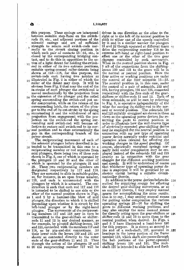
35 before referred to ‘,will be hereinafter de scribed and claimed‘ and are ilIustrated in E the accompanying drawings, in which—“ Figure 1 is ar sectional elevation, substan
tially. in‘ line 1—1 of Fig. 2, of a portionv of a type of gear-shifting mechanism having
40
separate energizing and operating power de- 5
l 1
Other features‘ of the invention not herein- _1 supplying 'means to put the operating de l
I
_power device for the purpose of storing en
1,115,877
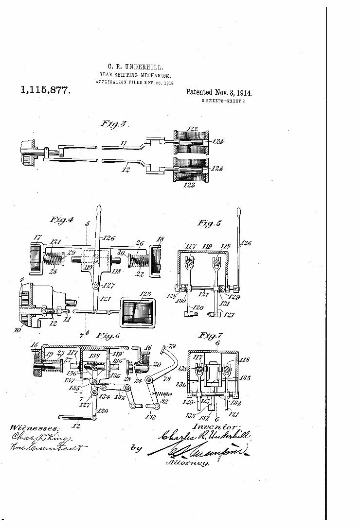
is a vertical transverse section and elevation of the same,'the section being taken in line 7—~7,Fig.‘6. L I _ ‘ I‘ -
Similar characters designate like parts in all the ?gures of the drawings; ' ' In carrying my present invention into
effect I may, as in my companion applica tion aforesaid, make use of any‘well-known
‘’ or suitable type of gearing capable of being shifted to different positions corresponding j: to-the various positions or speeds in or for which, such gearing may be set. The gear ing shown is a well-known type and is suit able ,for the purpose. I As the active or operating means for per— 51
forming the principal gear-shifting func tions I prefer to employ actuators in the form ofisprings energized vby suitable elec trical devices, such as solenoids, each- operat ing power device or spring preferably being J - normally in condition for performing its gear-shifting function. ‘The preferred op erating power ‘device is jone in which the. power is not only normally ready _' for use, but is one‘ in which the potential energy of .5 the device while available for substantiallyv instantaneous release is normally under re straint. The energizing power deviceem ployed in connection with this operating
Cl
ergy in said operating device is preferably an electrical device or solenoid energized by current in a suitable power circuit, this elec trical device or solenoid serving as a power
100 ; vice or spring under compression, in which condition it will be held until its work is to be performed, when the spring, which con stitutes here the powereapplying means, will beireleased and its potential energy will L05
vices and circuits governing different gear shifting movements, and illustrating one
' embodiment of my present-invention; Fig. ‘ 2Tis a‘sectional plan and diagrammatic view of said gear-shifting mechanism, the section being taken in line 2—'2, Fig?ll; Figf3 is a.
- sectional plan of the lower portion or the 50 apparatus shown in Fig. 1,, illustrating
mainly the shifter-rods and the means for shifting them to their neutral positions, they section being taken 'in line 3—3, Fig. 1'; Fig. 4 is a side elevation of the. major por-.
5_5 tion of the mechanism shown in Fig. 1, and illustrates both manual and power means for energizing the operating ‘power devices§ Fig. 5 is a vertical transverse section of the same," the section'being taken in line~5--5-, Fig. 4; Fig. 6 is. apvertical longitudinal sec .tion‘and elevation of a modi?cation of said gearfshifting mechanism, illustrating man ual means ‘for mechanically restoring the
> shifter-rods to neutral position, the section
become instantaneously kinetic and will shift a gear substantially instantaneously to a new position- , ' _ .
In Fig. 1 I,have shown “a well-known type of change-speed gearing in which the re- 11;“; spective gears are indicated at 2, 3,4,- 6, 7, 8, 9 and‘lO. These gears'and their move ments are under the control of suitable . gear-shifting mechanism the - principal mechanical elements of which, as illustrated herein, are a pair of gear-shifters or shifter rods, 11 and 12, carrying the usual shifter arms, 13 and 14:. Each of these gear-shift- ~> ers or shifter-rods is movable‘ to three po-. sitions, one of which is’ its neutral position in which the gears controlled by it are out of mesh, and the other two are active posi t-ions corresponding to diiferent speeds or ' directions of speed, as the case may be. In
120
\the present case, in the construction shown 125 in Figs. 1 to 5 inclusive, each of these gear shifting movements to working posrtions .or to neutral position is intended to be effected ' by a different actuator instead of all ofthem
65 being taken in line 6L6, Fig. 7,fand Fig. 7 i being effected>by a single actuator as in my 130
_ 1,115,877
‘ aforesaid companion application' In the embodiment of the invention illustrated in
' ' these- ?rst ?ve views each of the movements
. '10
of the gear-shifting mechanism to a work ing position is illustrated as derlved from a. diiferentenerglzing power device in the
I _ -_ form of a solenoid, the “four solenoids shown being designated respectively by 15, 16, 17 and 18, and their cores or plungers by” 19, 20, 21 and 22. The pullof these plungers
' when energized serves to put under com pression springs, such as 23, 24, 25 and 26,
“- - each of which is located between a collar,
20
27, 28, 29 or 30, at the outer endof its re \ sp'ective plunger and the frame or case oh its individual solenoid. On each energiza tion' of any one of these solenoids its plun-" ger is drawn in to the limit of its'stroke and the corresponding spring consequently is compressed at such time to its maximum ex tent. j In this position the spring is intended to be heldiuntil released for the purpose of shifting a gear to‘ the newj'positi‘on. Any
- suit-ablel_means may be employed for the purpose of holding each spring energized, that is, under compression. Here I have shown spring-held latches, such as 31, 32, 33
1 and '34, the nose of each of whichis adapt-' ed to engage in a corresponding notch in
'a' rod, 35, 36, .37 or 38’, forming an extension of the corresponding plunger 19, 20, 21 or
- 22,-'_ but made of‘ non-magnetic material”
40
4-5
to
‘Nhenany one of these plnngers is drawn in to the limit of its-in-stroke its latch will be pressed into the notch by a [suitable ‘spring, such as 39, 4t), 41 or 42, and the plunger and its extension,.together with the spring, 23, 24, 25 or 26, as. the case ‘may be, will be’ held under restraint until released and will maintain said spring in~ condition -for in stantaneous ‘release' of its stored energy'when its ‘latch is Withdrawn from the aforesaid notch. When s0 withdrawn the energized " operating power device vor spring'will i111 'stanta?eously niove‘ the corresponding - plun gerand its extension inward, as shown in Figs. 1 and 2, which movement will serve through suitable[power-transmitting connec tions to-shift- the correspondingogear of the speed gearing to a new position to bring about a change in speed. Herethe move ment of each solenoid-plunger ‘is trans? mitted'to a reciprocating member or rod suitably connected to other power. transmit-v
, ting elements, the operation of ‘which will be hereinafter described. ' ' - -
.The solenoids 15—18 are her’e‘connected? in a' ‘single powercircuit-in ‘such a manner that. each of the solenoids may-be sepa ratelv' energized momentarily, that is to say,
. just long “enough to perform the operation
5:3
of energizing the corresponding operating power device Pr spring. Immediately after a
_ this thecircuit of said solenoid should be broken, and in this case it is intended to re‘
main interrupted until the completion -,_of . > . L . . a
a cycle of operatlons of the energizing and operating power devlces governed by it, after which the circuit of said solenoid may ‘ be closed again. Each solenoid is here‘em ployed as the means for de'e'nergizing ‘itself, it serving, as’ in my,aforesaid companion‘ vapplication, to operate a switch for, opening ._a gap in the circuit through such solenoid. These gaps are shown as four in number, one for each of the solenoids 1~5—18, they
70
75
being located herein at the respective pairs . of contacts, >~13—4.4-, 45-46, 47—Ll8, and 49 by bridging contacts, such as 51~5l, op eratedv directly by'the extended ends ofthe plungers of said solenoids. vEach bridging contact k51—5i .is illustrated'as carried by. a switch-rod. 55458., though insulated there fromyas shown, ‘each of said switch-rods or slides being mounted in guides in the casé ings of the respective solenoids and having near its outer end a. projection in the path of an actuator or projection on the extended end of the ‘corresponding solenoid-‘plunger. ,These projections from the switch-rods are designated respectively by 59—62, and coact
50, whichvarecadapt'ed to be spanned - 80
with projections, 63—66, on the extensions - Qf the sclenoid-plungers; The parts,‘ are so’ combined that-at about the end of the-in stroke of each plunger the projection there on- will strike that. of the corresponding switch-rod and‘ shift said rod outward in -Fig; 2, ‘thereby opening up the power cir-V cuit and the gap controlled by the bridging‘ contact, which gap is intended to be nor mally closed. ’ '
100
Owing to the fact that’I employ in the ’ present case a plurality of solenoids and a plurality of parts operated ~ or controlled thereby,finstead.of a single set of these de~ vices, as shown in my aforesaid companion application, the electrical units in- the present case are preferably electrically con nected in multiple, the solenoids 15748 being, connected respectively in parallel branches of ap‘single main ‘power circuit, whilelsuit able controlling devices for». releasing the operating power’ devices energized by said solenoids will preferably be connected’in parallel branches of a - single *main con trolling circuit. The main power circuit
of energy, 67, through a ‘common conductor, 68, by way of four parallel branch ‘con ductors, 69, '70, 71 and '72 to the respective
10-3
110
illustrated hereinbis from a suitable ‘source ,
120
pairs of contacts ~l3——/l4, 45-46,,47——48 and _ ' 49—‘—50, whence four parallel branch~ con- @ ductors pass tolcorresponding ends ofithe] solenoids 15-18, the opposite ends of which are connected in turn by four parallel. branch conductors, 7 3-7 6, to a common‘ conductor, '77, leading from theother' side of source of energy 67. The power circuit also has in the main circuit thereof, as in my companion
125
130
4;
application, a circuit-controller, such as 78, operated by the pedal,‘ 7 9, of} the clutch-lever
. and‘ connected by a' conductor, 80, to said
10.
other side of the source of energy, the com mon conductor 7 7 vbeing connected to a con,-v tact, 81, governed by said circuit-controller. Thus, as in my companion application, here also there are vtwo breaks in the power cir-. cuit of each solenoid~15—'l8, one of which breaks is ata point governed by abridging contact, as before described, this break being
.‘controlled, as set- forth, .by an automatic
'15
20
circuit-controlleror switch. 'So far as the intermittent energization andv deenergiza tion of‘each solenoid is. concerned, the “break at such bridging contact is su?icient for the proper operation of the) apparatus. As a matter of convenience, however, a second break is shown,‘ which break may be em ployed in connection with motor vehicles‘ or other apparatus when desired. -This second.
_ break is, as juststated,~'common“to all of
25
the ,parallelvbranch circuits of the four sole ~noidsv 15-918 and is preferably normally closed by a power device, suitable ‘power devicefor the purpose is the'usual spring, 82, by means 1 of which the clutch-lever is
'1' held retracted.
30
[as
' - " It will be clear from-the foregoing that. whether the second 'gapju‘st' described’ is used or not the circuit at that point will always normally be closed, ‘so that current 'will ?ow momentarily through any one of the vsolenoids 15—18'when the other break (before described) ~ in the branch circuit of‘ that ‘solenoid is closed. In this speci?c -em-.
-'bodiment\of the invention, the. second gap is > automatically'maintained‘ closed by power
'40 and manual action is required to open it. , ‘As before indicated, the ‘release of the
potential energy of each operating v‘power device or spring 23—-26 is governed in this case by a single. controlling electrical cir- cuit._ This controlling ‘circuit, ' like the
' power, circuit, is intended to be~economical ‘of current and only momentarily closed, but it is‘ u like, the power‘ circuit'in that it is norma y open, ,there being here, as shown in Fig. 2, four‘ parallel-branches of this controlling circuit,‘ each branch con trolling a di?'erent one» of the solenoids
*15.-18 and each of said branches being nor-. mally. open. The current for the- control lin'gicircuit may be derived from, ‘the same source as the current for the power circuit, but the controlling ‘circuit will preferably consist mainly of ?ne wire' conductors and
: ‘_Will1 utilize but ‘little of the current'of the ‘source of energy in controlling ‘the opera; tion of thé‘gear-shifting- mechanism. " Each controlling circuit for ‘governing-one of said; solenoids must- have at least one break (‘and need have but one for the purpose‘ of~ controlling the maintenance of the neces'-' sary sequence ‘of operations of its"unit of
vof the
1,115,877- ‘ __
the mechanism) this break beingwsimilar to that at the bridging contact in‘ each branch
{power circuit in‘ that it is a break automa ically closed and opened intermit tently through the action of one of the solenoids ‘speci?ed. Unlikesaid break at the bridging contact in the power-"circuit branch,‘ however, this break vin the control ling circuit is normally open and is intended to be closed only‘ at the end of the in-stroke of the plunger of the corresponding solenoid and while said plunger and the operating device energized by the movement'thereof are ‘held under restraint. In the speci?c apparatus illustrated there are four con 80 trolling ‘branches of' this controlling cir- ' cuit, one for each solenoid" 15—18 and each of these branches is normally open, the nor= 'mally ‘open break therein- being that just referred'to as the‘ one necessary break in the controlling circuitof each?solenoid: ‘In Fig.‘ 2' these four breaks are shown as be'— tween ‘pairs of contacts, 83—84, 85—86, I 847588‘ and 89-90. f In each of'these pairs of contacts the‘ inner" and longer one is shown as in. position to belengaged by the end. of the extension of the corresponding solenoid-plunger and brought into engage - ment with the outer and shorter contact of - such pair substantially at themoment that said plunger reaches theendof'its in-stroke. In all other positions of each plunger the gap between the contacts of the pair 1'corre sponding thereto will be open. Each of ‘these pairs of contacts is illustrated here as connected in,a circuitlwith the source ‘of j, ‘energy 67 supplyingcurrent to the power circuit. kThe controlling circuit through each of these pairs‘of contacts is also illus trated as having an additional break or breaks which is or are provided for deter mining the times when the ‘devices con-' trolled thereby shall go. through their. se- . 'quence of operations, but which have no control over the time or sequence. of opera tions of any cycle after ‘such cycle is be? gun: Here there are two breaks in the con trolling circuit through each of the pairs 'of’contacts 83—84, etc., inaddition to that at said contacts. Onebf these “additional breaks is in the main line of the controlling circuit‘ - and is at the ‘circuit-controller _78.
100
105
governed'by the foot-lever or clutch-lever, ’ and is a break that is intended to manu-P ally closed vby the depression” _of said clutch lever. ~-The contact with which said clutch lever cooperates to'control this second break ' e controlling circuit of each solenoid, 111
1538 is‘indicated at 9'1. Said contact ‘is .- .~ shown as connected to a main line‘conduc tor,- 92, branches from which lead-to the respective contacts 88,- 84, 90 and 86, as shown at 93,'94,*95' and '96. In part the controlling ‘circuit follows the same, course as the power’ circuit, viz., through conduc-.
1,20
125
/
13E
p 68.
1,115,877
tor 80, source of energy 67, and conductor From said conductor 68, ‘however,
branches passv to the outer short contacts ._ 83, 85, 87 and 89 of “the pairs of contacts .I. previously described. Each of these branches embodies as its principal control ling element means, such as a small elec tromagnet, 97, 98, \99 or 100, for releasing the corresponding latch, 31, 32,,33'or 34, ‘to set free the potential energy oftlfe op erating power device or spring controlled thereby. Each parallel branch of the con
trolling circuit is shown as completed by , ?ne wire ' conductors extending from the _ heavier'conductor _68 through one of the controlling electromagnets 97—100 to the
_ corresponding contacts 83, etc., said’ conduc
, . 4 L")
tors being designated respectively by’il'0l, 102, 108.. and 104.’ Each of these branch circuits is also‘shown as having therein av _ manual controller or push-button, such as 1(_)5_—108, which may he interlocking, by means of which‘each branch of the control
' ling-circuit may be closed independently of
:so I
40
=. every other, On the closing of a branch cin f cuit by any one of these push-buttons the corresponding latch will be~released by the controlling electromagnet in thatlbranch in a manner which will be obvious. As soon as such latch is released the gap at the cor responding one of the four sets of contacts '83——8~i, etc, will be automatically opened‘ and " the corresponding solenoid-plunger will be quickly thrown to ‘the end of‘ its
' out-stroke by the operating power device or » spring surrounding it.- The - gap thus opened- in the branch .. circuit ,will remain open until said plunger reaches the end of its in-stroke again, and hence the controli ling branch circuit after being once closed
_ and its controlling electromagnet once ener
50
gized to release the" corresponding latch. cannot be closed [again until the solenoid corresponding thereto is again energized "by the power circuit‘ and the operating power vdevice or spring again energized by said “solenoid. The push-buttons l05—108 which are
preferably located ‘on the steering-head of the vehicle, constitute, as will be obvious, a
- means for controlling, and manually,» athird break in each controlling circuit that may
‘ be established through the connections shown _ < in Fig.v Thus, each such circuit that may
55
60
be established has in it three breaks all of. which are normally open and two, of which are; controlled by power-operated devices, one in. the main line of the controlling cir cuit and the other in an‘ individual par allel branch of the controlling. circuit, and automatically opened and closed by the ac
' tion of a solenoid corresponding to that
.5
branch. .
It will be seen from the ‘foregoing ‘that’ each of the power circuits before described
l .
that may be established through the main 7 line and the branch of such-power circuit ' is quite short and that ‘the solenoid, the source of energy and the automatic-switch constituting the principal means for mak-j ing and breaking eachsuch circuit may be quite close together and that the drop in any
over, as each branch is only momentarily closed, each being broken practically instan taneously atter-being made, the draft upon
.70
power circuit so closed will be slight. 'More- >
the battery will be maintained for the mini mum amount of time. In addition, during each brief period that a controlling circuit is established through one‘ of the parallel branches described but little current is used in it owing to the employment‘ ofa ?ne Wire
_ conductor through the major portion of that circuit. _ I _
The parts described for operating each bridging contact to open and close one of the
so
gaps at 43ft}, etc., and for operating one 1. of the long contacts 8st, etc., to close and open'automatically the respective gaps in the parallel’branches of the controlling cir—_ cuit, constitute double-throw switches gov— erned by the solenoids L5—18 andoperated in such‘a manner that each switch will al ternately and substantially. reciprocally open and close two gaps one in the power .circ-uit ranch and the other in the corre sponding controlling-circuit branch, and one on one stroke and the othernon the opposite l stroke of the corresponding soleno1d-plun-. . , ger, from which it 'will be clear that there can be no interference with the p,redeter- mined‘ sequence of’operations of the mech~n anism controlled and operated by any pan of corresponding branch circuits. On the in-stroke of a solenoid-plunger the corre sponding-spring 'will be compressed and latched and the break in the corresponding power-circuit branch then opened and that - K‘ _ . 0 n
‘in , the corresponding controlling-circuit branch then closed, and-‘on the release of the corresponding latch and the outward move ment of said plunger-the gap in said con trolling branch will be opened, and at the end of the out-stroke the gap in the power branch will be closed; and this regardless‘ of the manner in which the circuit-controller governed by the clutch-lever is ‘operated
100
105
I10
115
with respect to the contacts 81 and 91 of ._ the main line portions of the‘ power and _ . controlling circuits, and irrespective also of the order in, which the push-buttons 105, etc, ma be operated. ' .
' The projections from the switch-rods, 55, ' etc. and the extensions 35, etc, of the sole-‘ noid-plungers are su?icient forathe purpose of automatically opening‘ the breaks in the branches of the-power circuit, as-before de scribed. These breaks may be ‘‘closed ‘at the proper time in any suitable -manner, coil springs 109—-11__2 being shown herein for
120
125
130
i ' rods .55, etc., and-adjacent portions of the,
’ mally to the .circuit closing position sin‘
purpose. These springs are interposed between suitable stop-faces on the switch-\
solenoid casings and arev of su?cient strength to return .sa1d swltch erods nor-
which each pair of contacts 113-114, etc.,- is ‘ ,closed by the corresponding bridging con
15
20
tact, and .to .do this in opposition to the ac~ tioniof a light detent for holding the switch
‘ rod in ‘either .of its :two extreme positions, suitable spring-pressed roller-detents being shown '.at‘.113—116, for this purpose, the switch-rods each having- two notchesf as illustrated in Fig. 2 in either of which the roller of the detent may drop. ‘It will be obvious from Fig. 2 that near‘the end of the inestroke of each plunger the‘ switchlrod is moved mechanically by the projection from the exgtensionof the plunger vand the coiled spring surrounding the switch-rod put un der compression, while on the release .of the
, --corresponding "latch, the return of the plun ger to the end of its out-stroke by the spring
. surrounding it and the withdrawal-lot said ‘ projection‘ from engagement with the pro
jection ‘on the switch-rod the spring sur rounding said switch-rod will. become ef
, fective-ito ‘restore said switch-rod to its mor
- power circuit.
35
7301‘ ma’l position and to close automatically the gap in the‘ corresponding branch of the
The. ‘reciprocating movement of each of the solenoid plungers before described is in tended-to be transmitted in thiscase to .a reciprocating member or rod separate from said plungers, there being ‘two of these rods showngin Fig.2, one of which is operated by the plungers 19 and 20 and the other of whichis operated by the plungers 21 and 22. These {two reciprocating. members are designated respectively ,by 117 and 118. They are mounted to slide in suitable guides,
' as, for instance, in an open frame member, [119, and each- is unconnected with the plungers by which it is actuated. The con struction is such that each rod 117 and 118 is intended ‘to be shifted to one side or the‘
' other of the normal posit-ion shown in Figs.. 50
55
' and 121, connected with themembers 117 and I 60
65
1 and 2 by a hammer-‘like blow of said ' plunger, the direction to which it is shifted depending upon whether. it isistruckby the ‘left-hand plunger or by‘ the right-hand plunger. The movements'of the_'reciprocat mg "members 117 and 118 may‘ in turn be transmitted to the gear-‘shifters or shifter rods '11land'12in any desired manner, as for example, by pivoted shifting-levers, 120
118, as 'by pin-and-slot' connections. At their lower ends the levers 120 and 121 are shown‘ as connected directly to the outer ends of the gear-shifters 11 and 12. Thus - through the action of the plungers 1? and 20 the reciprocating member 117 Wlll be
1,115,877
driven inone direction .or. the other to the, right or to the left of its normal position to shift to either one of .the speedscontrolled by it and, in a similar manner the plungers ‘ 21 and 22' though operated at different times drivethe reciprocating member 118~to its extreme left-hand or right-hand position to e?ect one .or the other of the two gear 'changes controlled by ‘such movements. ,“When in the normal ipositionshown in Fig. ~, ‘1 all~_.of the connections from the shifting‘ level-s12!) and 121 to .the gears will ‘be in I the normal or neutral position. Here the tour active or Working posit-ions are under the control of the four Isolenoids 15-18. _a The neutral position is, in this case, ,under the control of a pair of solenoids, 122 and 123, having plu-ngers, 12a and 125,-c0nnected respectively with the free ends of the gear ,shifters .or shifter-rods 11 and 12. . Each of‘ these solenoids, as .will be seenby referring
‘to Fig. 3, is operative vindependently of the other for moving its-shi?ter-rod to ,the 110T". anal or neutral position. Thesolenoids 122 and 123 suitably energized are shown in these views as the operating power devices i?or re_ turning the ,parts to neutral position in order to illustrate how the well-knownity‘pe .of electrically-operated gear¢shifting device may be employed .sforthe neutral. position in connection with my new type of operating power device normally under restraint and operative when released for e?ecting ,the working changes in the ispeed gearing. Of ieoiu'se, electrically energized springs nor really‘ held ‘under compression may be em ployed instead iof the solenoids 122 and 123 :exactly as in connection with the gear
for the \dilierent working‘ positions and speeds It will be understood of course that whichever type of operating power .de rice is employed it W111 be goyerned by an electric circuit having a suitable circuit .controller therein. - ,_ - . p
In addition to the power .deylces before de scribed tor supplying-energy for \effecting the desired gear-shifting movements,‘ ,or'as an auxiliary thereto, I may {employ manual , .means for accomplishing the same results, that is to say, I may employ manual means‘ for putting under compression the various operating springs 23-26 for shifting the gears to \di?erenlt working positions, and
also employ .the same manual ,means for directly acting upon the gear-shifters or vshifter-rods 11 and 12 to move .them to .the neutral position when desired. vIn Figs. 4 andq5 I have illustrated a hand-lever 126 vfor this purpose. It is shown as secured .to the end of a rock-shaft, E127, mounted in hearings .in the lower portion of the frame member 119, which shaft also passes through the hub portions of the power-operated shifting levers 120 and 121. The rock shaft 127 is intended to slide back and forth
1,00
110
115
12L
.125
1,115,877‘ , ' ‘ p '2?
in its lbearingsand is illustrated as‘having secured thereto a pair of oppositely-facing clutch‘ members, 128,.and 129, adapted to
' ’ engage complementary clutch= members 130 and ‘131, on the power operated shifting
: leversil20 and 121.‘ By shiftingthe manual lever 126 sidewise the rock-shaft 127 may be correspondingly moved ‘endwise either to
‘ ‘the neutral position shown in Fig. 5 or to a 10 plurality?of other positions corresponding
to the working positions of,the levers 120 * and 121. a
The selection of the desired gear-shifting operation, whether to a working position or to neutral position, will of course be deter-v mined by the operation of a push-button, suchv as 105. etc., or other suitable device. In the speci?c construction shown in Fig. 2 of course tliecir‘cuit for releasing any of the operating springs .will not actually be closed until~ the pedal 79 is depressed, but, as before shown, it is not necessary to em~ ploy an additional controlling break in the combined controlling and power circuit, or‘ to govern such a break'b'y'the- clutch-lever. Of course the neutralizing-solenoids 122 and
‘ 123 may also be connected in circuit with the single source of energy 67 . In case the source of energyor battery should fail the
a necessary gear-shifting operations bothvto neutral and working positions will of course
40
be performed, in the :qaparat’usillustrated, by manipulation of the lever 126‘ both lengthwise of its axis and about that axis. In Figs. 6 and 7 I have illustrated a modi
?cation of the invention in which the parts are in many respects the same as, or ‘similar to, those shown in the-other views, the ener gizing solenoids, the operating power de vices or springs, the plungers, the recipro
._ catoryomember operated thereby, the power ' operated shiftingdevers, the gear-shifters or shifter rods, and the clutch-lever being the same as in the other views and designated by the‘ same reference characters.
> ‘however,- of employing in'this modi?cation
'. have illustrated mechanical devices for this’ 50'
60
55
separate solenoids, such as 122 and 123, for returning the parts to neutral position I
purpose, which devices are operated by the clutch-lever 78. These connections here ‘embody an angle-lever, 132, operated from the clutch-lever 78 through a‘ connecting rod, 133, and carrying at‘its free or working end a by-pass pawl, 134, adapted to engage the under side of a stop, 135, on a vertically reciprocatory cam, 136, mounted to slide in the frame, member 119'; This cam has two cam-faces, 136’ and 136", and‘ a locking notch, 137 , between them, theparts being so combined as to cooperate with aprojection, preferably an .antifriction roller on the end of a pin, 138, ‘on the power-operated shift~ ing-lever- 121, for the purpose of restoring said shifting-lever ‘to its central or neutral
Instead, -
position and'with it the gears of the change-v i speed/mechanism. The manner-in‘ which , this is accomplished is well understood and will be obvious from the drawings. “That I claim is: i .
1. Gear-shifting mechanism, comprising in combination‘ with shiftable gears, a plu rality of separately-operative normally ener gized gear-shifting power devices, and means for releasing said‘power devices separately.
2. Gear -shiftingmechanism, comprising,
70
75
in; combination‘ with a set ‘of interrelatedv ‘ speed-changing gears, a plurality of sepaj rately-operative normally energized power devices each operative for moving agear from oneposition to another, and separate _ means for normally holding said respective power devices under restraint.
, 3. Gear-shiftingmechanism, comprising. in-vcombination' with gearing embodying a; pluralityof gears each shiftable from one working position to another through neu,-. tral position,~a plurality of separately-op erative normally {energized power devices, each operative for moving a gear from one
80
85
90, working position through neutral position to . another working position, and separate means for normally holding said respective power devices under restraint. ' ,
4; Gear- shifting mechanism, comprising, inv combination with a set of interrelated speed-changing ‘ gears, a plurality of ~ sepa-_ rately-operative ‘normally energized power devices each operative for moving a gear from one position to another, separate means for normally holding said respective power devices under restraint, andmeans for re
' leasing said power devices separately. 5. Gear -s_hifting~ mechanism, comprising,
in combination with a set of interrelated speedmhanging gears, a plurality of sepa rately-operative springs each operative for moving a gear from one position to-another, and separate means for normally holding said . respective springs un der ; restraint.
. 6. Gear-shifting mechanism. comprising. in combination with gearing embodying a plurality of’ gears each shiftable from, one working position to another through neu-_ tral position, a plurality of separately-op erative springs each operative for moving a gear from one workingposition through neutral position to another working posi tion, and separate means for normally hold ing said respective springs'under restraint.
7. Gear-shifting mechanism, comprising, in combination with a set of interrelated speed-changing gears, a plurality of sepa rately-operative normally -.energized power devices each operative for moving a gear
95'
100
105
110
115"
120
125 from one position to another, separatev means for normally holding said respective power devices under restraint, and electrical controlling means for releasing said power devices separately. 130

8 v.
8. Gearlshiftinoi mechanism, comprising,’ ' in- combination with a set of lnterrelated speed-"changing gears, aplurality of» sepa rately-operative sprlngs each operative for
a moving a gear from one position to another, separate means for ‘normally holding said respective- springs under restraint, and elec- _ trical controlling means-tor releasin‘g said springs separately. r
9. Gear-shifting mechanism, comprising, in combination ‘with a set of interrelated speed-changing gears, a plurality of oper rately-operatii'l‘e spring each operative for ating power devices separately operative for moving~corresponding gears respectively each from one position to another, and sepa rate ‘means for, energizing said operating:
1 power devices. I
v |
. plurality of gears each shiftable from one working position to another ‘through neu-.
35
10. Gearishifting mechanism, comprising, in combination with a set of interrelated speed-changing gears, a plurality of oper ating power devices separately operative ‘for moving corresponding gears respectively leach from ‘one position to another, and a, plurality of energlzlng power devices sep_a-' 'rately operative for energizing said respec-' the operating‘ power devices.
11. Gear-shifting mechanism, comprising, in, combination’with gearing embodying a plurality of gears‘. each shiftable from one working position to another throughneu tral position, aplurality of operating power devices separately operative' for ' moving corresponding gears respectively each from‘ one working position through neutral'posi tion to another working position, and a_plu-' ralit-y of energizing power devices separately operative for energizing said respective op- ' arating power devices. _ " s
12. Gear-shifting mechanism, comprising, in‘combinaticn with a set of interrelated speed-changing gears, a plurality of operat ing power devices ‘separately operative for moving corresponding gears respectively each from one position to another, a plural ity of energizing power devices separately operative for energizing said respective oper ating power devices,-means for maintaining each operating power device in, its energized condition, and means for releasing sepa .rately said energized operating power de- vices. .
4 13. Gear-shifting mechanism, comprising in combination with gearing embodying a
.tral position, a plurality of‘ operating‘power devices of one character separately operative for moving corresponding gears respectively each from one working position to another‘, and separate energizing power devices of another character’ foryenergizing said respec tive operating power devices, '
14.1. Gear-shifting mechanism, comprising, in'combination with a set "of interrelated,
> for shifting each individual gear.
’ after the starting‘of the same.
1,115,877
speed-changing gea-rs,_a plurality of operat ing power devices separately operative- for . moving corresponding“ gears respectively each from one position to.-_another, and sepa rate electrical. power devices for energizing‘ said respective operating power devices sepa~ rately. ‘ r‘ ' _
15. Gear-shifting mechanism, comprising, in combination with‘ a, set of interrelated speed-changing gears, a plurality of operat ing power devices separately operative for' moving corresponding gears respectively
70
:15;
each from one'position to another, and sepa- v _ ratcly operative solenoids for-energizing said respective operating power ‘devices sepa-‘ rately. > ' ‘ -
so'
16. Gearshifting mechanism, comprising,’ ' in combination with a set of interrelated speed-changing gears, a plurality of springs vseparately operatlve for moving correspond- , lng gears respectively each from one position. to another, and separately-operative electri cal power devices for storing energy in said springs. - , e . ,
'17. Gear-shifting mechanism, comprising, in combination ‘with a set of interrelated speedéchanging’gearea plurality [of pairs of
85
90
,power devices the ?rst device of each pair ' being operative for shifting a gear and the . second de ice of each pairbeing operative» ‘for energizlng the ?rst, and separate control— ling means for said respective energizing power devices. ' - ‘ " \
18. Gear-shiftin mechanism, comprising, in combination wlth a setof interrelated‘ ,speedjchanging gears, a plurality of pairs'of power devices the ?rst device of each pair being operative-for shifting a gear and the second device of each pair being operative forenergizing the ?rst, and separate power operated controllers for governing the action ofsaidfrespective ‘energizing power devices.
19. Gear-shifting mechanism, comprising, in combination with a. set of interrelated 'speedrchanging’ gears, a plurality .of pairs of powerdevices the?rst device of each pair being'o'perative for shiftingia gear and the second device of each pair being operative for energizing the ?rst, and separate con- trollers for said respectiveoperating. power devices. , ' _ - “I - ‘
p '20. Gear-shifting mechanism, comprising, means for supplying‘ and applying power for shifting individual gears, and separately-op erative‘ devices for‘ automatically determin ing‘ the period ofxtime that power is supplied.
21.‘ ‘Gear-shifting mechanism, comprising, means for supplying and applying powerfor shifting individual gears, separate devices
100
105
110
for starting the action of said power-‘supply; - ing means for each gear, and ‘separately-0p 'erative devices ,f'o'r‘automatically stopping. each such action at a predetermined time
130
1,115,877
22. Gear-shifting mechanism, comprising, a plurality of separately-operative electrical devices for supplying power for bringing‘ about the shifting of individual gears, means for separately energizing said electrical de vices, and separately-operative automatic de vices for deénergizing said electrical devices respectively.
23. Gear-shifting mechanism, comprising, a plurality of separately-operative electrical devices for supplying power for bringing about the shifting of individual gears, means for separately energizingsaid electrical de
' vices, and separately-operative automatic de vices each controlled by the action of a dif ferent one of said electrical devices for de energizing that device at a predetermined
. moment after the beginning of its energiza » tion. > '
20
25
30
40
45
124. Gear-shifting mechanism, comprising, an electric circuit having a plurality of
‘ parallel branches each’branch of which con tains a device for supplying power for bring ing about the shifting of one of a plurality of gears and also contains an automatic de vice for determining the period of said sup ply, and a manual circuit-controller govern ing all of said branches. . ‘
25. Gear-shifting mechanism, comprising,‘ an electric circuit having a plurality of parallel branches each branch of which con tains a solenoid for supplying power for bringing about the shifting of one of a plu rality of gears, and a plurality of automatic devices each controlled by a different one of said branch-circuits and each operative for making its respective solenoid circuit on one stroke of the solenoid-plunger and for break ing said circuit on the other stroke of said. plunger.
26. Gear-shifting mechanism, comprising, in. combination with a set of interrelated speed-changing gears, a plurality of sepa rately-operative pairs of power devices the first device of each pair. being operative at one time for shifting a gear and the ‘second device of each pair. being operative at a‘ diiferent time for energizing the‘ ?rst.
27.. Gear-shifting mechanism, comprisinv, in ‘ combination with a set ofinterrelated speed-changing gears, a plurality of sepa-_
. _ rately operative pairs of power devices the
55
?rst device of each pair beingoperative at one time for shifting a gear and, the second device of each pair being operative at'a di?'erent time and from a source of; power of a di?erent character for energizing the first. . '
28. Gear-shiftin mechanism, comprising, in combination with a set of interrelated speed-changing gears, a plurality of sepa rately-operative pairs of power’ devices the ?rst device of each pair being operative at one time for shifting a gear and the second device of each pair being operative .at a
' 9
different time and for a relatively ‘short period for energizing the ?rst,‘
29. Gear-shifting mechanism, comprising, in combination with a 'set .of interrelated speed-changing gears, a plurality of op‘ erating power devices separately operative for moving individual gears each from one position to another, ‘and electrical means for effecting separately a substantially instan taneous energization of each of said/op erating power devices. v ' _
30. Gear-shifting mechanism, comprising, in combination with a set of interrelated speed-changing gears, a plurality of operat- . ing power devices separately operative for moving 1ndividual gears each from one po sition to another, electrical means for e?ect ing separately 'a substantially instantane ous energization of each of said operating, power devices, and a plurality of separate devices for maintaining said operating power devices respectively in their ener gized condition. '
31. Gear-shifting mechanism, comprising, a plurality of separately-operative pairs of power devices the ?rst device of each pair being operative atone time for shifting a
. gear and the second device of each pair be ing an electrical device operative at a diifer ent time for energizing the ?rst, all of said electrical devices being connected in parallel branches of a common energizing circuit.
32. Gear-shifting mechanism, comprising,‘ in ‘combination with a set of interrelated speed-changing gears, a plurality of sepa rately-operative pairs of powerv devices the first device of each pair. being operative at one time for shifting a gear and the second device of each pair being 'a solenoid 0p erative at a different time for energizing the ?rst, and separately-operative devices for substantially instantaneously‘ making and breaking the circuits of said. respective sole noids. ..
Gear-shifting mechanism, comprising, a plurality of operating power devices sepa— rately operative for moving individual gears each from one position to, another, and means for simultaneously energizing- all of said operating power devices.
34. Gear-shifting mechanism, comprising, a plurality of‘operating power devices sepa rately operative fO1‘~‘_II10VlDg individual gears each from one position to another, and power-operated means for bringing about the simultaneous energization of all ofvsaid operating power devices. -
35. Gear-shifting mechanism, comprising, a plurality of operating power devices sepa rately operative for moving individual gears each from one position to another, and elec-' trical means for simultaneously energizing all of said operating'power devices. '
36. Gear-shifting mechanism, comprising, a plurality of operating power devices sepa
70
76
80
86
90
105
110
115
120
~rately operative for moving individual gears I each from’ one position to anotherameans
10
15
for- simultaneously energizing all of said operating power devices, and controlling means for releasing said'power devices s'ep arately. p‘ Q '
> 37. Gear-shifting mechanism, comprising, a plurality, of'operating power devices sep arately operative for moving individual gears each from‘onefposition to another,
' power-operated means for bringing about the simultaneous energization of all of said operating ipowerdevices, vand manual con trolling means for bringing about the re lease of said power devices separately.
38JGear-shifting mechanism, comprising, . a pluralityfof operating power devices sepa-. rately-operativc for moving individual gears 'each' from ‘.one position to another, means for simultaneously energizin all‘of said operating power devices, an separate de vices for latching each of said energized operating power devices. . -
. i139. Gear-shifting mechanism, comprising, a plurality of operating power) devices sepa rately operative. for moving each from ,one position to another, means for silnultane-j ouslyenergizing /all of said operating power
; devices, separate devices .forv latching each 30, and means orreleasing sai
35
110
of said ener ized operating ower devices,
~vices separately? . \ ~ , _
‘ 40. . Gear-shifting ‘mechanism, comprising gear-shifting means having ‘a plurality of gear-shifting _. movements, a single power circuit having a plurality of“ parallel branches eachwincluding electrical means for supplying energy for‘ bringing \about one of said, ‘movements, and controlling means for. releasing said energy. ' -
41. Gear-shifting mechanism, comprising ' gear-shifting means having a plurality of__ gear-shifting movements,‘ a single power circuit, vhaving a plurality of parallel branches each including electrical means for supplying energy for. bringing’ about one of said movements, and a controlling circuit for releasing the energy of said
" electrical means. . a '
42., Gear-‘shifting mechanism, comprising ‘gear-shifting means having a plurality of
> gear-shifting movements, a single power
.55
circuit having a plurality of parallel branches each including electrical means for supplying energy for bringing about one
' of said movements, and asin'gle controlling
.60
65
circuit having -a plurality. of‘ parallel branches each including electrical means for releasing the energy stored byya correspond- \ ing branch'of the power circuit. . .
_ 43. Gear-shifting mechanism, comprising a power circuit having alplurality of par allel branches each containing an automatic‘ circuit-controller for breakingsaid branchv circuit at the end of a predetermined
latching‘ del
.and the
1,115,877
‘period. and also including electrical means for. supplying ‘energy foribringing about the shifting of a gear from one position to another, and a controlling circuit for re- ‘
' 70 leasing said energy." 44;. Gear-shifting \mechanism, comprising
a power circuit having a plurality of par allel branches each containing an automatic circuit-controller for breaking said ‘branch circuit at the end of a predetermined period and also including electrical means for supplying energy. for. bringing about ‘the shifting of a gearv from one position to another, andva controlling circuit having a plurality of parallel branches each hav ing an automatic circuit-controller gov erned by said electrical means. I
_ 45. Gear-shifting mechanism, comprising a power circuit, having a plurality of‘par allel branches each containing an automatic circuit-controller for breaking said branch circuit at the end of a - predetermined
80
period and alsoincluding‘electrical means . for supplying energy for bringing about shifting of a gear from one position ‘to an other, and‘ a controlling circuit having a ‘plurality ‘of parallel branches, each branch of the power circuit and each branch of ‘the controlling circuit having an automatic circuit-controller one of which is open when‘ that oflthe corresponding branch circuit is closed.- . .
46. Gear-shifting mechanism, comprising a' plurality of ‘springs for shifting .corre sponding gears, a power circuit having a plurality of .parallel, branches each includ ing a solenoid for energizing a correspond-.. ing spring, and a controlling circuit having a plurality _, of parallel branches each in cluding means for releasing ‘a correspond" inglspring, each, branch of the power cir cuit“ and each branch of thecontrolling cir cuit having an automatic‘ circuit-controller
' controllers [of corresponding branchesrof such circuits being opened and closed substantially reciprocally. ’ .
47. Gear-shifting ‘mechanism, comprising a plurality ‘of springs for shifting corre
90
100
105
110
sponding gears, a power circuit having a" plurality ofparallel'branches each includ ing a solenoid for energizing a corres'p'onda ving spring, a controlling circuit having a‘ plurality of parallel brancheseach ‘includ ing ,means for releasing a corresponding spring, ‘and a plurality of double-throw switches operated respectively by said, sole-' noid-plungers and'each operative for open ing a break in itsv branch of the power cir cuit and closing one in the corresponding
12o ;
branch of the controlling circuit on one7l25 vstroke‘of itsplunger and for closing said break ‘in the‘ power circuit and opening ‘that in the controlling circuit on the other" stroke of said plunger. . ‘48. Gearéshifting mechanism, comprising 130'“
I
.10
15
20
25
1,115,877
a. plurality of springs for shifting corre sponding gears, a power circuit having a. plurality of parallel branches‘ each includ ing a solenoid‘ for energizing a correspond ing spring, a controlling circuit having a plurality of parallel. branches each includ ing means for releasing a corresponding spring, a plurality of double-throw switches operated respectively by said solenoid-plun gers and ‘each operative for opening a. break in its branch of the power circuit and closing one in the corresponding branch of the controlling circuit on one stroke of its plunger and for closing said break in the, power circuit and opening that in the controlling circuit on the other stroke of said plunger, and a circuit-controller‘ gov erning anotherbreakin the main line of each of said circuits and operative for closing them alternatively.
49. Gear-shifting mechanism, comprising a plurality of springs for shifting correspond ing gears, a power circuit having a plurality of parallel branches each including a sole noid for energizing a corresponding spring,
-. a controlling circuit having a plurality of
30
35
40
55
parallel branches each including means for releasing a corresponding spring, a plurality of double-throw switches operated respec tively by Said solenoid-plungcrs and each OP'I' erative for opening a break in its branch of the power circuit and closing one in the cor responding branch‘bf the controlling circuit on one stroke of its plunger and for closing said break in the power circuit and opening that in the controlling circuit on the other stroke of said plunger, and a circuit-con troller operated by the clutch~lever and gov erning another break in the main line of each of said circuits and operative for closing them alternatively and having means for normally moving it into position for closing said break in the main line‘ of the power. circuit. _ >
50. Gear-shifting mechanism, comprising a plurality of operating power devices sepa rately operative for moving individual gears each from one position to another, and a'plu rality of sets of energizing, latching and re leasing power devices one set for each op erating power device, the energizing de vices of all sets being simultaneously op erative and the latching devices of all sets being also simultaneously operative and the releasing devices of the different sets being separately operative.
51. Gear-shitting mechanism, comprising gear-shifting means havin a plurality of gear-shifting movements, a p urality of op erating power devices for effecting said movements respectively, and an electrical
' power circuithaving a plurality of parallel branches each including means for energiz- ' ing the corresponding operating power de vice.
52. Gear-shifting mechanism, comprising a gear-shifting element, and an operating power device normally under restraint and normally out of contact with said gear shifting element and adapted when released “to force-the same to a newposition.
53. Gear-shifting mechanism, comprising
11
70
a gear-shifting element, and a spring-op- ‘ erated actuator normally under restraint and normally out of contact -with said gear~ shifting element and adapted when released to force the same to a new position.
54. Gear-shifting mechanism, comprising a gear-shifting element, and a plurality of > operating power devices each normally un der restraint and normally out of contact with said gear-shifting element and oper ative separately when released for forcing said gear-shifting element to one position or another.
55. Gear-shifting mechanism, comprising a gear-shifting element, a plurality of spring-operated actuators each normally un der restraint and normally out of contact with said gear-shifting element, and oper ative separately when released for striking said gear-shifting element a sharpblow and driving it to one position or another.
75
80
85
90
56. Gear-shifting mechanism, comprising ~ a gear-shifting element, an ‘operating power device normally out of contact- With said gear-shifting element and adapted wherire ileased to force the same to a new position, a power circuit embodying means for energiz ing said operating power device, and a con trolling circuit for releasing said operating power device. - ' .
57. Gear-shifting mechanism, comprising a gear-shifting element, a plurality of spring-operated actuators each ‘normally out ' of contact with said gear-shifting element and each adapted when released to strike said element‘ a sharp blow and drive it to one of a plurality of new positions, a power circuit embodying means for simultaneously energizing all of said springs, and a con trolling circuit. embodying means for releasé ing said springs separately.
95
100
105
‘58. Gear-shifting mechanism, comprising, . in combination with a gear, a spring for moving said gear from OIIG'POSltlOIl to an
means for holding said energized spring un der restraint, an automatic circuit-controller governing the circuit of said solenoid and movable to one circuit-controlling position by said solenoid. andr a separate spring for moving ‘said circuit~controller to its ‘other circuit-controlling position. -
59. Gear-sh'fting mechanism, comprising, in combination with a gear, a spring for moving said gear from one position to an other. a solenoid for energizing said spring and having a plunger the out-stroke of which is derived from the power of said
115
a, other, a solenoid for, energizingsaid spring, I
120
125
130
.12
spring, means‘for holding‘ said energized 'sprlng under restraint, an automatic cir»
'- cuit-controller governing the circnit of said
10
solenoid and operative for opening a break‘ in the solenoid‘ circuit on the energization of said solenoid, and a separate spring for “operating said circuit-controller to close said break in the solenoid circuit on the deener g'ization of said solenoid; ‘ ' '
' 60. Gear-shifting mechanism, comprising, a relatively short power circuit of low re sistance‘ having a' plurality‘ _'of‘ parallel
‘branches each containing an automatic cir wit-‘controller governing said branch and also contaimn electrical means for storing energy for shi ing a gear from one position > to another. v _
Signed at New Haven in the county of New Haven and State of Connecticut this 22d day of November, A. DJ 1913. v
CHARLES‘R. UNDERHILL. Witnesses: . ‘
' MARY A. MURPHY,‘ EVA M. VIsEL..