g timers gt3
TRANSCRIPT
7/28/2019 g Timers Gt3
http://slidepdf.com/reader/full/g-timers-gt3 1/41
GT3A Series Timers
G-14 www.idec.com USA: (800) 262-IDEC or (408) 747-0550, Canada: (888) 317-IDEC
G
Timers
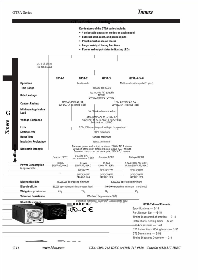
GT3A Series — Analog Timers
GT3A-1 GT3A-2 GT3A-3 GT3A-4,-5,-6
S p e c i f i c a t i o
n s
Operation Multi-mode Multi-mode with inputs (11 pins)
Time Range 0.05s to 180 hours
Rated Voltage100 to 240V AC, 50/60Hz
12V DC
24V AC, 50/60Hz / 24V DC
Contact Ratings 125V AC/250V AC, 3A;30V DC, 1A (resistive load)
125V AC/250V AC, 5A;30V DC, 5A (resistive load)
Minimum ApplicableLoad
5V, 10mA (reference value)
Voltage ToleranceAF20 (100V AC): 85 to 264V AC
AD24: 20.4 to 26.4V AC/21.6 to 26.4V DCD12: 10.8 to 13.2V DC
Error ±0.2%, ±10 msec (repeat, voltage, temperature)
Setting Error ±10% maximum
Reset Time 60msec maximum
Insulation Resistance 100MΩ minimum
Dielectric Strength Between power and output terminals: 2,000V AC, 1 minuteBetween contacts of different poles: 2,000V AC, 1 minuteBetween contacts of the same pole: 750V AC, 1 minute
Power Consumption(approximate)
Delayed SPDTDelayed SPDT +
instantaneous SPDTDelayed DPDT Delayed DPDT
10.8VA(200V AC, 60Hz)
13.5VA(200V AC, 60Hz)
14.4VA(200V AC, 60Hz)
4.7VA (100V AC, 60Hz),14.4VA (200V AC, 60Hz)
–
12VDC/1W 12VDC/1.1W 12VDC/0.8W
24VDC/0.7W24VAC/1.2VA
24VDC/0.6W24VAC/1.3VA
24VDC/0.6W24VAC/1.3VA
Mechanical Life 10,000,000 operations minimum 5,000,000 operations minimum
Electrical LIfe 50,000 operations minimum (rated load) 100,000 operations minimum (rated load)
Weight (approximate) 63g 73g 79g 80g
Vibration Resistance 100m/sec2
(approximate 10G)
Shock Resistance Operating extremes: 100m/sec2 (approximate 10G)Damage limits: 500m/sec2 (approximate 50G)
Operating Temperature –10 to +50°C
Operating Humidity 45 to 85% RH
Storage Temperature –30 to +80°C
Housing Color Gray
Key features of the GT3A series include:
• 4 selectable operation modes on each model
• External start, reset, and pause inputs
• Panel mount or socket mount
• Large variety of timing functions
• Power and output status indicating LEDs
UL, c-uL Listed
File No. E55996
GT3A Table of Contents
Specifications — G-14
Part Number List — G-15
Timing Diagrams/Schematics — G-16
Instructions: Setting Timer — G-22
GT3 Accessories — G-48
GT3 Instructions: Wiring Inputs — G-50
GT3 Dimensions — G-52
Timing Diagrams Overview — G-4
7/28/2019 g Timers Gt3
http://slidepdf.com/reader/full/g-timers-gt3 2/41
Timers GT3A Series
www.idec.com USA: (800) 262-IDEC or (408) 747-0550, Canada: (888) 317-IDEC G-15
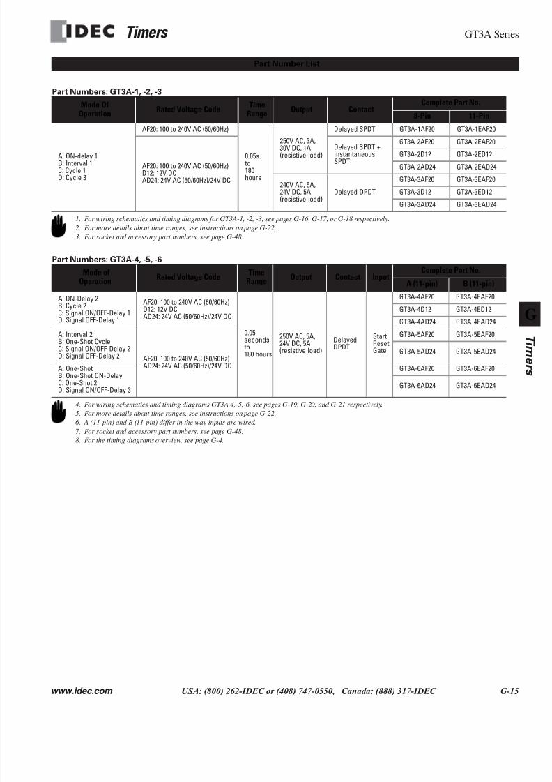
Part Numbers: GT3A-1, -2, -3
Part Numbers: GT3A-4, -5, -6
Mode OfOperation
Rated Voltage CodeTime
RangeOutput Contact
Complete Part No.
8-Pin 11-Pin
A: ON-delay 1B: Interval 1C: Cycle 1D: Cycle 3
AF20: 100 to 240V AC (50/60Hz)
0.05s. to180hours
250V AC, 3A,30V DC, 1A(resistive load)
Delayed SPDT GT3A-1AF20 GT3A-1EAF20
AF20: 100 to 240V AC (50/60Hz)D12: 12V DCAD24: 24V AC (50/60Hz)/24V DC
Delayed SPDT +InstantaneousSPDT
GT3A-2AF20 GT3A-2EAF20
GT3A-2D12 GT3A-2ED12
GT3A-2AD24 GT3A-2EAD24
240V AC, 5A,24V DC, 5A(resistive load)
Delayed DPDT
GT3A-3AF20 GT3A-3EAF20
GT3A-3D12 GT3A-3ED12
GT3A-3AD24 GT3A-3EAD24
Mode ofOperation Rated Voltage Code TimeRange Output Contact Input Complete Part No.A (11-pin) B (11-pin)
A: ON-Delay 2B: Cycle 2C: Signal ON/OFF-Delay 1D: Signal OFF-Delay 1
AF20: 100 to 240V AC (50/60Hz)D12: 12V DCAD24: 24V AC (50/60Hz)/24V DC
0.05seconds to180 hours
250V AC, 5A,24V DC, 5A(resistive load)
DelayedDPDT
StartResetGate
GT3A-4AF20 GT3A-4EAF20
GT3A-4D12 GT3A-4ED12
GT3A-4AD24 GT3A-4EAD24
A: Interval 2B: One-Shot CycleC: Signal ON/OFF-Delay 2D: Signal OFF-Delay 2 AF20: 100 to 240V AC (50/60Hz)
AD24: 24V AC (50/60Hz)/24V DC
GT3A-5AF20 GT3A-5EAF20
GT3A-5AD24 GT3A-5EAD24
A: One-ShotB: One-Shot ON-DelayC: One-Shot 2D: Signal ON/OFF-Delay 3
GT3A-6AF20 GT3A-6EAF20
GT3A-6AD24 GT3A-6EAD24
Part Number List
1. For wiring schematics and timing diagrams for GT3A-1, -2, -3, see pages G-16, G-17, or G-18 respectively.
2. For more details about time ranges, see instructions on page G-22.
3. For socket and accessory part numbers, see page G-48.
4. For wiring schematics and timing diagrams GT3A-4,-5,-6, see pages G-19, G-20, and G-21 respectively.
5. For more details about time ranges, see instructions on page G-22.
6. A (11-pin) and B (11-pin) differ in the way inputs are wired.
7. For socket and accessory part numbers, see page G-48.
8. For the timing diagrams overview, see page G-4.
7/28/2019 g Timers Gt3
http://slidepdf.com/reader/full/g-timers-gt3 3/41
GT3A Series Timers
G-16 www.idec.com USA: (800) 262-IDEC or (408) 747-0550, Canada: (888) 317-IDEC
G
Timers
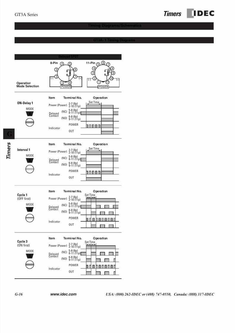
Delayed SPDT
ON-Delay 1
Interval 1
Cycle 1(OFF first)
Cycle 3(ON first)
Timing Diagrams/Schematics
GT3A- 1 Timing Diagrams
OperationMode Selection
1
2
6
5
7
8
4
3
POWER
(+)(-)
1
2
65 7
84
3
POWER
(+)(-)
9
10
11
8-Pin 11-Pin
A
MODE
OUT
Item
Power
Delayed
Indicator
Terminal No. Operation
2-7 (8p)2-10 (11p)(Power)
5-8 (8p)8-11 (11p)(NC)
6-8 (8p)9-11 (11p)(NO)
POWER
Set Time
Contact
B
MODE
Item
Power
Delayed
Indicator
Terminal No. Operation
2-7 (8p)2-10 (11p)(Power)
5-8 (8p)8-11 (11p)(NC)
6-8 (8p)9-11 (11p)(NO)
POWER
OUT
Set Time
Contact
C
MODE
Item
Power
Delayed
Indicator
Terminal No. Operation
2-7 (8p)2-10 (11p)(Power)
5-8 (8p)8-11 (11p)(NC)
6-8 (8p)9-11 (11p)(NO)
POWER
OUT
Set Time
Contact
D
MODE
Item
Power
Delayed
Indicator
Terminal No. Operation
2-7 (8p)2-10 (11p)(Power)
5-8 (8p)8-11 (11p)(NC)
6-8 (8p)9-11 (11p)(NO)
POWER
OUT
Set Time
Contact

7/28/2019 g Timers Gt3
http://slidepdf.com/reader/full/g-timers-gt3 4/41
Timers GT3A Series
www.idec.com USA: (800) 262-IDEC or (408) 747-0550, Canada: (888) 317-IDEC G-17
Delayed SPDT + Instantaneous SPDT
ON-Delay 1
Interval 1
Cycle 1(OFF first)
Cycle 3(ON first)
GT3A- 2 Timing Diagrams
OperationMode Selection 1
2
6
5
7
8
4
3
POWER
(+)(-) 2
65 7
84
3
POWER
(+)(-)
9
10
111
8-Pin 11-Pin
A
MODE
Item
Power
Delayed
Indicator
Terminal No. Operation
2-7 (8p)2-10 (11p)(Power)
5-8 (8p)8-11 (11p)(NC)
6-8 (8p)9-11 (11p)(NO)
POWER
OUT
Set Time
Contact
1-4
1-3
(NC)
(NO)
Instan- taneousContact
B
MODE
Item
Power
Delayed
Indicator
Terminal No. Operation
2-7 (8p)2-10 (11p)(Power)
5-8 (8p)8-11 (11p)(NC)
6-8 (8p)9-11 (11p)(NO)
POWER
OUT
Set Time
Contact
1-4
1-3
(NC)
(NO)
Instan- taneousContact
C
MODE
Item
Power
Delayed
Indicator
Terminal No. Operation
2-7 (8p)2-10 (11p)(Power)
5-8 (8p)8-11 (11p)(NC)
6-8 (8p)9-11 (11p)(NO)
POWER
OUT
Set Time
Contact
1-4
1-3
(NC)
(NO)
Instan- taneousContact
D
MODE
Item
Power
Delayed
Indicator
Terminal No. Operation
2-7 (8p)2-10 (11p)(Power)
5-8 (8p)8-11 (11p)(NC)
6-8 (8p)9-11 (11p)(NO)
POWER
OUT
Set Time
Contact
1-4
1-3
(NC)
(NO)
Instan- taneousContact
7/28/2019 g Timers Gt3
http://slidepdf.com/reader/full/g-timers-gt3 5/41
GT3A Series Timers
G-18 www.idec.com USA: (800) 262-IDEC or (408) 747-0550, Canada: (888) 317-IDEC
G
Timers
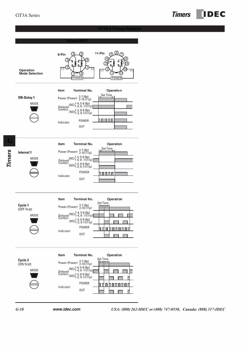
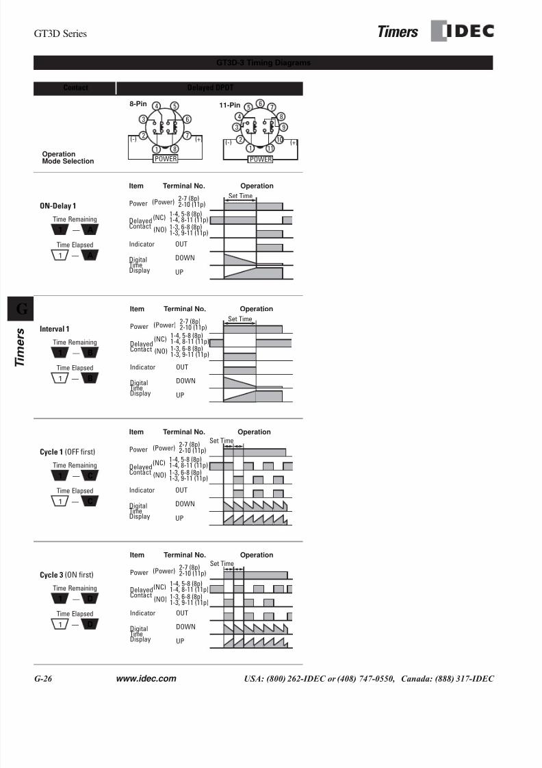
Delayed DPDT
ON-Delay 1
Interval 1
Cycle 1(OFF first)
Cycle 3(ON first)
GT3A-3 Timing Diagrams
OperationMode Selection 1
2
6
5
7
8
4
3
POWER
(+)(-) 2
65 7
84
3
POWER
(+)(-)
9
10
111
8-Pin 11-Pin
A
MODE
Item
Power
Delayed
Indicator
Terminal No. Operation
2-7 (8p)2-10 (11p)(Power)
(NC)1-4, 8 -11(11p)
(NO)
POWER
OUT
Set Time
Contact
1-4, 5-8 (8p)
1-3, 9-11(11p)1-3, 6-8 (8p)
B
MODE
Item
Power
Delayed
Indicator
Terminal No. Operation
2-7 (8p)2-10 (11p)(Power)
POWER
OUT
Set Time
Contact
(NC)1-4, 8 -11(11p)
(NO)
1-4, 5-8 (8p)
1-3, 9-11(11p)1-3, 6-8 (8p)
C
MODE
Item
Power
Delayed
Indicator
Terminal No. Operation
2-7 (8p)2-10 (11p)(Power)
POWER
OUT
Set Time
Contact
(NC)1-4, 8 -11(11p)
(NO)
1-4, 5-8 (8p)
1-3, 9-11(11p)1-3, 6-8 (8p)
D
MODE
Item
Power
Delayed
Indicator
Terminal No. Operation
2-7 (8p)2-10 (11p)(Power)
POWER
OUT
Set Time
Contact
(NC)1-4, 8 -11(11p)
(NO)
1-4, 5-8 (8p)
1-3, 9-11(11p)1-3, 6-8 (8p)
7/28/2019 g Timers Gt3
http://slidepdf.com/reader/full/g-timers-gt3 6/41

7/28/2019 g Timers Gt3
http://slidepdf.com/reader/full/g-timers-gt3 7/41
7/28/2019 g Timers Gt3
http://slidepdf.com/reader/full/g-timers-gt3 8/41
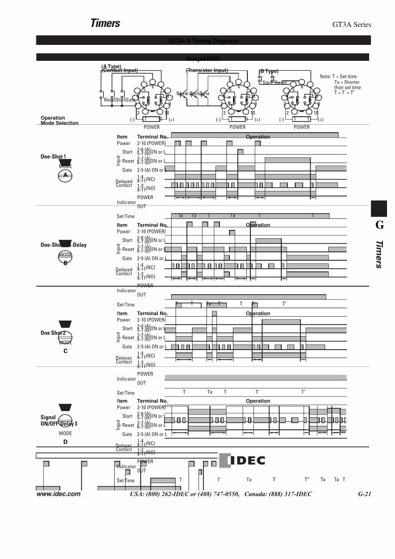
Timers GT3A Series
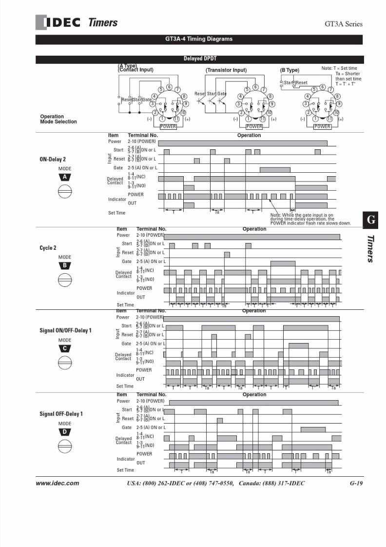
www.idec.com USA: (800) 262-IDEC or (408) 747-0550, Canada: (888) 317-IDEC G-21
Delayed DPDT
One-Shot 1
One-Shot ON-Delay
One Shot 2
SignalON/OFF-Delay 3
GT3A- 6 Timing Diagrams
OperationMode Selection
2
65 7
843
POWER
(+)(-)
9
10
111
ResetStartGate
2
65 7
843
POWER
(+)(-)
9
10
111
Reset StartGate
2
65 7
843
POWER
(+)(-)
9
10
111
Start Reset
(A Type)(Contact Input) (Transistor Input) (B Type)
Note: T = Set timeTa = Shorter
T = T' + T" than set time
A
MODE
2-10 (POWER)
2-6 (A)5-7 (B)ON or L
2-7 (A)6-7 (B)ON or L
2-5 (A) ON or L
1-48-11(NC)
1-39-11(NO)
POWER
OUT
Set Time
Indicator
DelayedContact
I n p u t
Start
Reset
Gate
Power
Item Terminal No. Operation
Ta T'TaT T"Ta
B
MODE
2-10 (POWER)
2-6 (A)5-7 (B)ON or L
2-7 (A)6-7 (B)ON or L
2-5 (A) ON or L
1-48-11(NC)
1-39-11(NO)
POWER
OUT
Set Time
Indicator
DelayedContact
I n p u t
Start
Reset
Gate
Power
Item Terminal No. Operation
T T'TTaT T T"
C
MODE
2-10 (POWER)
2-6 (A)5-7 (B)ON or L
2-7 (A)6-7 (B)ON or L
2-5 (A) ON or L
1-48-11(NC)
1-39-11(NO)
POWER
OUT
Set Time
Indicator
DelayedContact
I n p u t
Start
Reset
Gate
Power
Item Terminal No. Operation
T T'TTa T"
D
MODE
2-10 (POWER)
2-6 (A)5-7 (B)ON or L
2-7 (A)6-7 (B)ON or L
2-5 (A) ON or L
1-48-11(NC)
1-39-11(NO)
POWER
OUT
Set Time
Indicator
DelayedContact
I n p u t
Start
Reset
Gate
Power
Item Terminal No. Operation
T TaT T' T"’ Ta Ta T
7/28/2019 g Timers Gt3
http://slidepdf.com/reader/full/g-timers-gt3 9/41
GT3A Series Timers
G-22 www.idec.com USA: (800) 262-IDEC or (408) 747-0550, Canada: (888) 317-IDEC
G
Timers
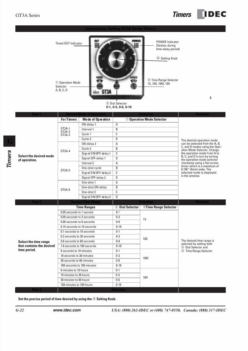
Step 1. Desired Mode of Operation Selection Remarks
Select the desired modeof operation.
For Timers Mode of Operation ➀ Operation Mode Selector
The desired operation modecan be selected from the A, B,C, and D modes using the Oper-ation Mode Selector. Change the operation mode from A toB, C, and D in turn by turning the operation mode selectorclockwise using a flat screw-driver which is a maximum of0.156” (4mm) wide. Theselected mode is displayedin the window.
GT3A-1GT3A-2GT3A-3
ON-delay 1 A
Interval 1 B
Cycle 1 C
Cycle 3 D
GT3A-4
ON-delay 2 A
Cycle 2 B
Signal ON/OFF-delay 1 C
Signal OFF-delay 1 D
GT3A-5
Interval 2 A
One-shot cycle B
Signal ON/OFF-delay 2 C
Signal OFF-delay 2 D
GT3A-6
One-shot 1 A
One-shot ON-delay B
One-shot 2 C
Signal ON/OFF-delay 3 D
Step 2. Desired Time Range Selection Remarks
Select the time range
that contains the desired time period.
Time Ranges ➁ Dial Selector ➂Time Range Selector
The desired time range isselected by setting both➁ Dial Selector and➂ Time Range Selector.
0.05 seconds to 1 second 0-1
1S0.05 seconds to 3 seconds 0-3
0.05 seconds to 6 seconds 0-6
0.15 seconds to 18 seconds 0-18
0.1 seconds to 10 seconds 0-1
10S0.3 seconds to 30 seconds 0-3
0.6 seconds to 60 seconds 0-6
1.8 seconds to 180 seconds 0-186 seconds to 10 minutes 0-1
10M18 seconds to 30 minutes 0-3
36 seconds to 60 minutes 0-6
108 seconds to 180 minutes 0-18
6 minutes to 10 hours 0-1
10H18 minutes to 30 hours 0-3
36 minutes to 60 hours 0-6
108 minutes to 180 hours 0-18
Step 3. Selection
Set the precise period of time desired by using the➃ Setting Knob.
Instructions: Setting GT3A Series Timers
POWER Indicator(flashes during time-delay period)
➃ Setting Knob
➂ Time Range Selector1S, 10S, 10M, 10H
➁ Dial Selector0-1, 0-3, 0-6, 0-18
➀ Operation Mode
SelectorA, B, C, D
Timed OUT Indicator
A
7/28/2019 g Timers Gt3
http://slidepdf.com/reader/full/g-timers-gt3 10/41
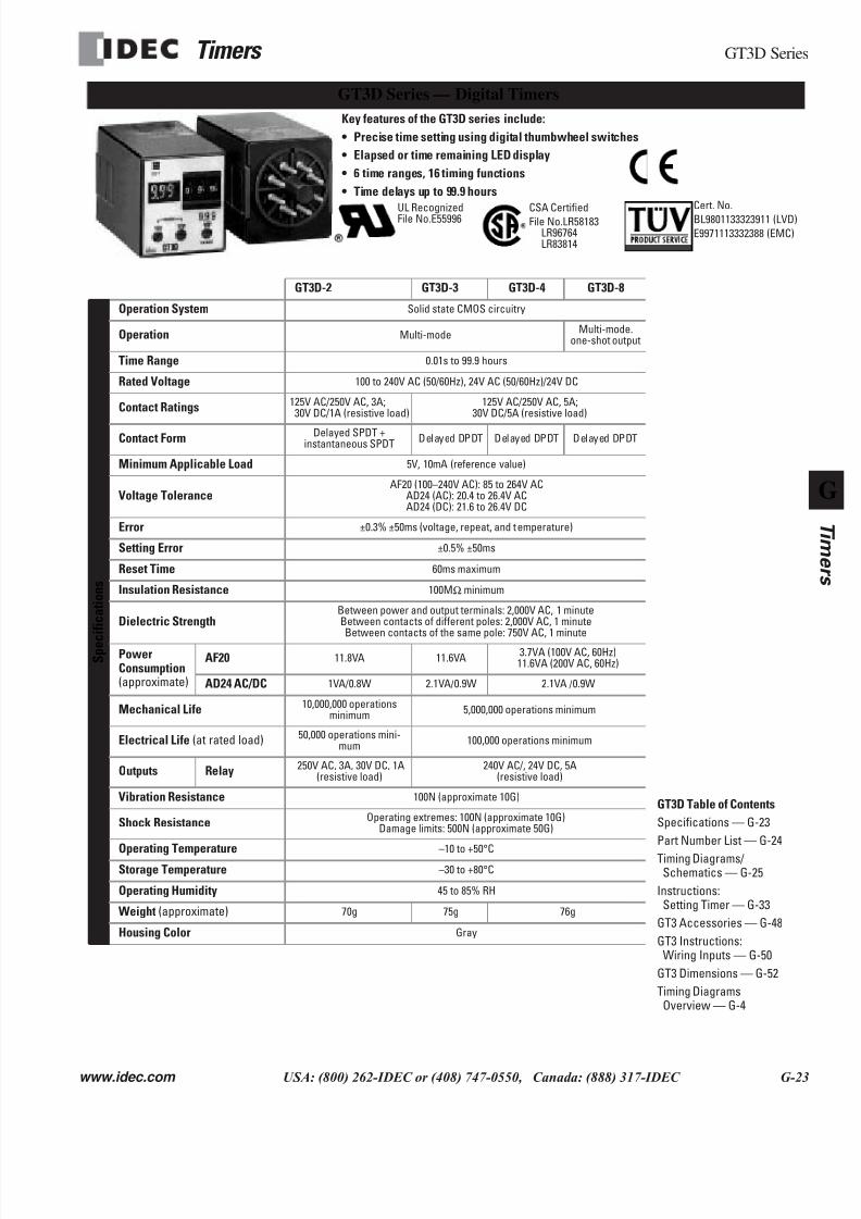
Timers GT3D Series
www.idec.com USA: (800) 262-IDEC or (408) 747-0550, Canada: (888) 317-IDEC G-23
GT3D Series — Digital Timers
GT3D-2 GT3D-3 GT3D-4 GT3D-8
S p e c
i f i c a t i o n s
Operation System
Solid state CMOS circuitry
Operation
Multi-modeMulti-mode.
one-shot output
Time Range
0.01s to 99.9 hours
Rated Voltage
100 to 240V AC (50/60Hz), 24V AC (50/60Hz)/24V DC
Contact Ratings
125V AC/250V AC, 3A;30V DC/1A (resistive load)
125V AC/250V AC, 5A;30V DC/5A (resistive load)
Contact Form
Delayed SPDT +instantaneous SPDT
Delayed DPDT Delayed DPDT Delayed DPDT
Minimum Applicable Load
5V, 10mA (reference value)
Voltage Tolerance
AF20 (100–240V AC): 85 to 264V ACAD24 (AC): 20.4 to 26.4V ACAD24 (DC): 21.6 to 26.4V DC
Error
±0.3% ±50ms (voltage, repeat, and temperature)
Setting Error
±0.5% ±50ms
Reset Time
60ms maximum
Insulation Resistance 100M
Ω
minimum
Dielectric Strength
Between power and output terminals: 2,000V AC, 1 minuteBetween contacts of different poles: 2,000V AC, 1 minuteBetween contacts of the same pole: 750V AC, 1 minute
PowerConsumption
(approximate)
AF20 11.8VA 11.6VA3.7VA (100V AC, 60Hz)11.6VA (200V AC, 60Hz)
AD24 AC/DC
1VA/0.8W 2.1VA/0.9W 2.1VA /0.9W
Mechanical Life
10,000,000 operationsminimum
5,000,000 operations minimum
Electrical Life (at rated load)
50,000 operations mini-mum
100,000 operations minimum
Outputs Relay
250V AC, 3A, 30V DC, 1A(resistive load)
240V AC/, 24V DC, 5A(resistive load)
Vibration Resistance
100N (approximate 10G)
Shock Resistance
Operating extremes: 100N (approximate 10G)Damage limits: 500N (approximate 50G)
Operating Temperature
–10 to +50°C
Storage Temperature
–30 to +80°C
Operating Humidity
45 to 85% RH
Weight (approximate)
70g 75g 76g
Housing Color
Gray
Key features of the GT3D series include:
• Precise time setting using digital thumbwheel switches
• Elapsed or time remaining LED display
• 6 time ranges, 16 timing functions
• Time delays up to 99.9 hours
UL RecognizedFile No.E55996
Cert. No.
BL9801133323911 (LVD)
E9971113332388 (EMC)
CSA Certified
File No.LR58183LR96764LR83814
GT3D Table of Contents
Specifications — G-23
Part Number List — G-24
Timing Diagrams/Schematics — G-25
Instructions:Setting Timer — G-33
GT3 Accessories — G-48
GT3 Instructions:Wiring Inputs — G-50
GT3 Dimensions — G-52
Timing DiagramsOverview — G-4
7/28/2019 g Timers Gt3
http://slidepdf.com/reader/full/g-timers-gt3 11/41
GT3D Series
Timers
G-24 www.idec.com USA: (800) 262-IDEC or (408) 747-0550, Canada: (888) 317-IDEC
G
Timers
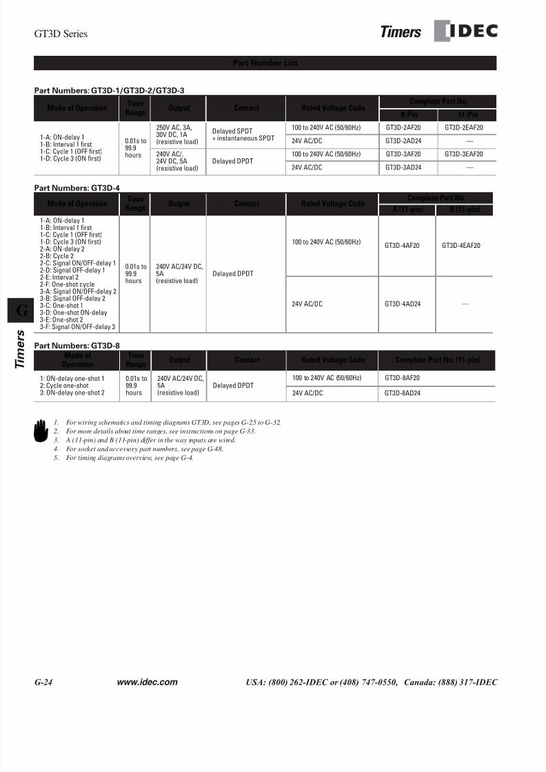
Part Numbers: GT3D-1/GT3D-2/GT3D-3
Part Numbers: GT3D-4
Part Numbers: GT3D-8
Mode of OperationTime
RangeOutput Contact Rated Voltage Code
Complete Part No.
8-Pin 11-Pin
1-A: ON-delay 11-B: Interval 1 first1-C: Cycle 1 (OFF first)1-D: Cycle 3 (ON first)
0.01s to99.9hours
250V AC, 3A,
30V DC, 1A(resistive load)
Delayed SPDT+ instantaneous SPDT
100 to 240V AC (50/60Hz) GT3D-2AF20 GT3D-2EAF20
24V AC/DC GT3D-2AD24 —
240V AC/,24V DC, 5A(resistive load)
Delayed DPDT100 to 240V AC (50/60Hz) GT3D-3AF20 GT3D-3EAF20
24V AC/DC GT3D-3AD24 —
Mode of OperationTime
RangeOutput Contact Rated Voltage Code
Complete Part No.
A (11-pin) B (11-pin)
1-A: ON-delay 11-B: Interval 1 first1-C: Cycle 1 (OFF first)1-D: Cycle 3 (ON first)2-A: ON-delay 22-B: Cycle 22-C: Signal ON/OFF-delay 1
2-D: Signal OFF-delay 12-E: Interval 22-F: One-shot cycle3-A: Signal ON/OFF-delay 23-B: Signal OFF-delay 23-C: One-shot 13-D: One-shot ON-delay3-E: One-shot 23-F: Signal ON/OFF-delay 3
0.01s to99.9hours
240V AC/24V DC,5A(resistive load)
Delayed DPDT
100 to 240V AC (50/60Hz)GT3D-4AF20 GT3D-4EAF20
24V AC/DC GT3D-4AD24 —
Mode ofOperation
TimeRange
Output Contact Rated Voltage Code Complete Part No. (11-pin)
1: ON-delay one-shot 12: Cycle one-shot3: ON-delay one-shot 2
0.01s to99.9hours
240V AC/24V DC,5A(resistive load)
Delayed DPDT100 to 240V AC (50/60Hz) GT3D-8AF20
24V AC/DC GT3D-8AD24
Part Number List
1. For wiring schematics and timing diagrams GT3D, see pages G-25 to G-32.
2. For more details about time ranges, see instructions on page G-33.
3. A (11-pin) and B (11-pin) differ in the way inputs are wired.
4. For socket and accessory part numbers, see page G-48.
5. For timing diagrams overview, see page G-4.
7/28/2019 g Timers Gt3
http://slidepdf.com/reader/full/g-timers-gt3 12/41
Timers
GT3D Series
www.idec.com USA: (800) 262-IDEC or (408) 747-0550, Canada: (888) 317-IDEC G-25
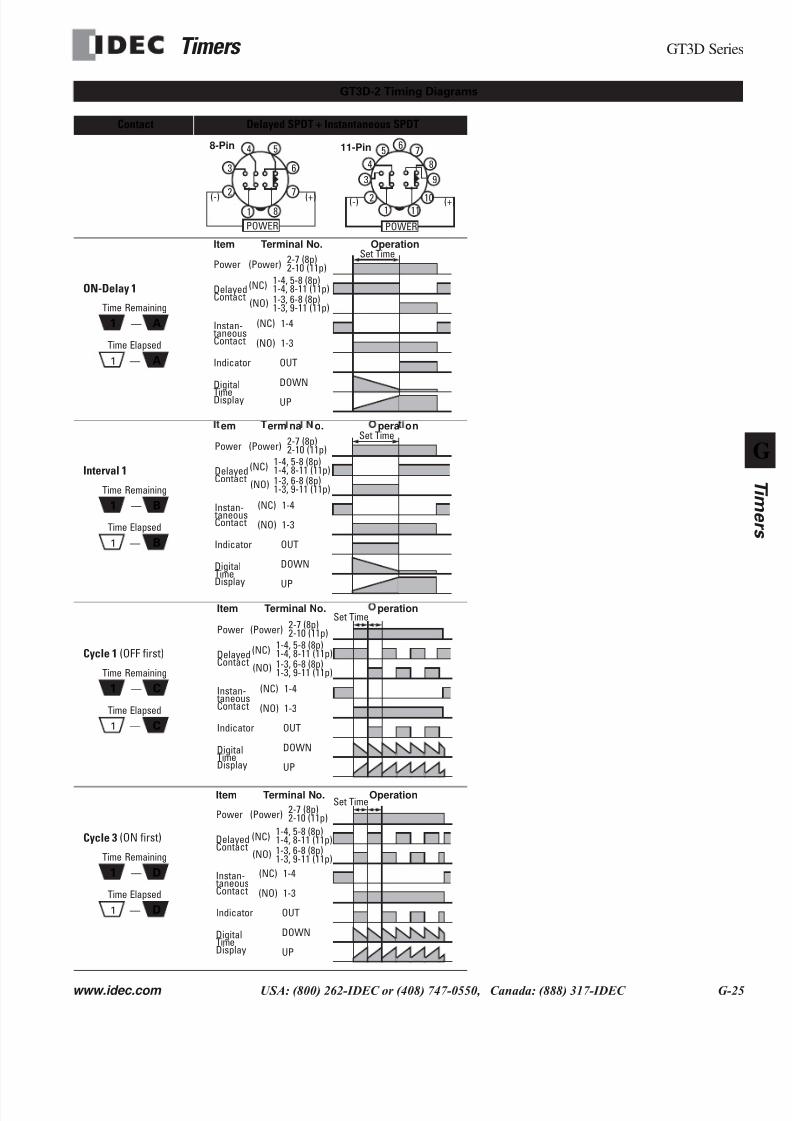
Contact Delayed SPDT + Instantaneous SPDT
ON-Delay 1
Interval 1
Cycle 1 (OFF first)
Cycle 3 (ON first)
GT3D-2 Timing Diagrams
12
6
5
78
4
3
POWER
(+)(-) 2
65 7
84
3
POWER
(+)(-)
9
10111
8-Pin 11-Pin
1 A
A1 —
—
Time Remaining
Time Elapsed
Item
Power
Delayed
Indicator
Terminal No. Operation
2-7 (8p)2-10 (11p)(Power)
1-4, 5-8 (8p)1-4, 8-11 (11p)(NC)
1-3, 6-8 (8p)1-3, 9-11 (11p)(NO)
UP
Set Time
Contact
OUT
DOWNDigital
TimeDisplay
1-4
1-3
(NC)
(NO)
Instan- taneousContact
1 B
B1 —
—
Time Remaining
Time Elapsed
em
Power
Delayed
Indicator
erm na o. pera on
2-7 (8p)2-10 (11p)(Power)
UP
Set Time
Contact
OUT
DOWNDigitalTimeDisplay
1-4
1-3
(NC)
(NO)
Instan- taneousContact
1-4, 5-8 (8p)1-4, 8-11 (11p)(NC)
1-3, 6-8 (8p)1-3, 9-11 (11p)(NO)
1 C
C1 —
—
Time Remaining
Time Elapsed
Item
Power
Delayed
Indicator
Terminal No. peration
2-7 (8p)2-10 (11p)(Power)
UP
Set Time
Contact
OUT
DOWNDigitalTimeDisplay
1-4
1-3
(NC)
(NO)
Instan- taneousContact
1-4, 5-8 (8p)1-4, 8-11 (11p)(NC)
1-3, 6-8 (8p)1-3, 9-11 (11p)(NO)
1 D
D1 —
—
Time Remaining
Time Elapsed
Item
Power
Delayed
Indicator
Terminal No. Operation
2-7 (8p)2-10 (11p)(Power)
UP
Set Time
Contact
OUT
DOWNDigitalTimeDisplay
1-4
1-3
(NC)
(NO)
Instan- taneousContact
1-4, 5-8 (8p)1-4, 8-11 (11p)(NC)
1-3, 6-8 (8p)1-3, 9-11 (11p)(NO)
7/28/2019 g Timers Gt3
http://slidepdf.com/reader/full/g-timers-gt3 13/41
7/28/2019 g Timers Gt3
http://slidepdf.com/reader/full/g-timers-gt3 14/41
Timers
GT3D Series
www.idec.com USA: (800) 262-IDEC or (408) 747-0550, Canada: (888) 317-IDEC G-27
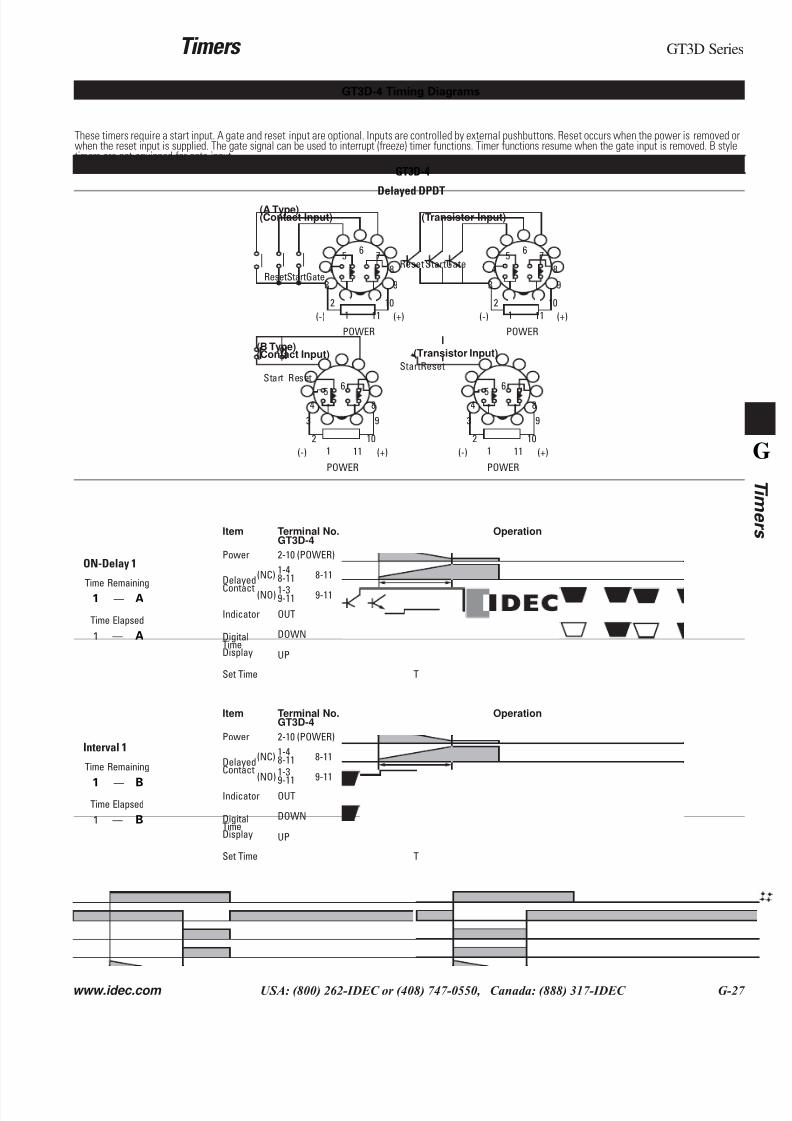
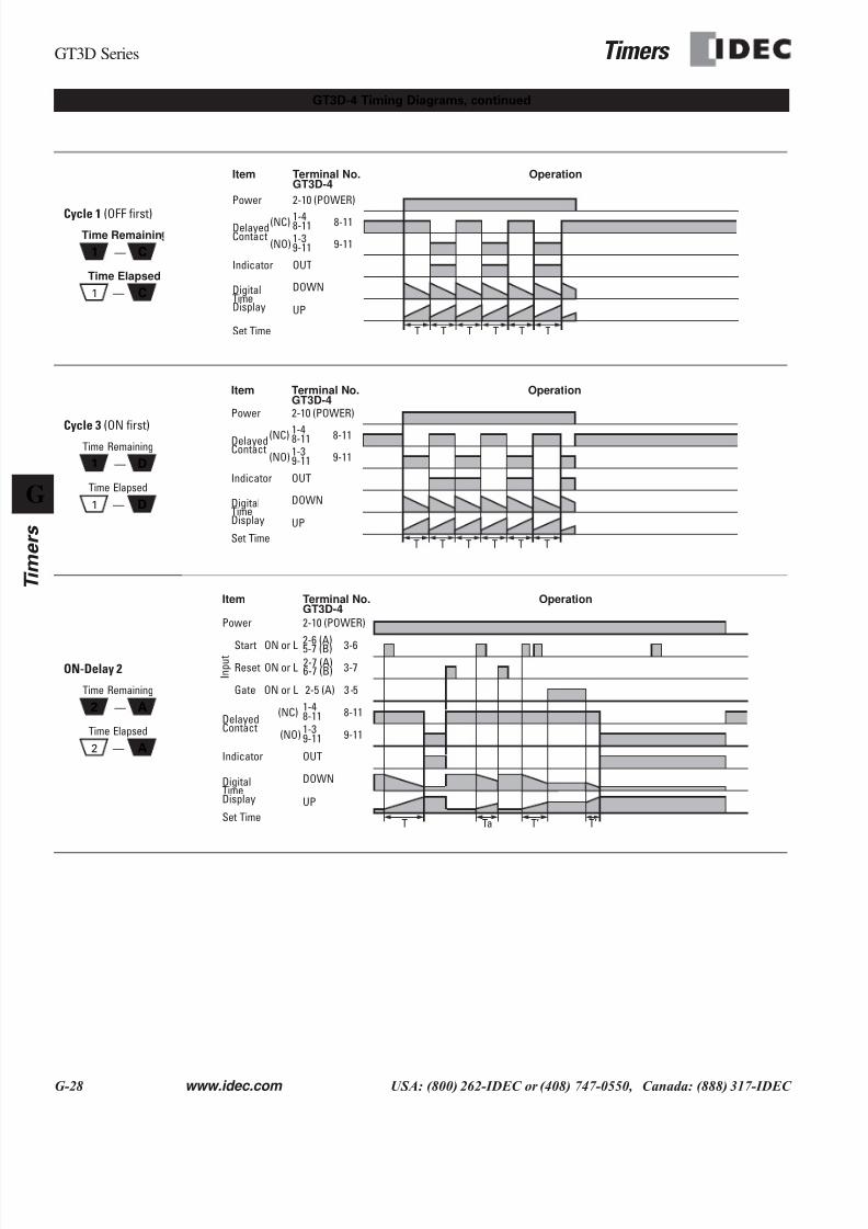
These timers require a start input. A gate and reset input are optional. Inputs are controlled by external pushbuttons. Reset occurs when the power is removed owhen the reset input is supplied. The gate signal can be used to interrupt (freeze) timer functions. Timer functions resume when the gate input is removed. B styltimers are not equipped for gate input.
GT3D-4
Delayed DPDT
ON-Delay 1
Interval 1
GT3D-4 Timing Diagrams
2
65 7
84
3
POWER
(+)(-)
9
10
111
ResetStartGate
2
65 7
84
3
POWER
(+)(-)
9
10
111
Reset StartGate
2
65 7
84
3
POWER
(+)(-)
9
10
111
Start Reset
2
65 7
84
3
POWER
(+)(-)
9
10
111
StartReset
(A Type)(Contact Input) (Transistor Input)
(B Type)(Contact Input) (Transistor Input)
1 A
A1 —
—
Time Remaining
Time Elapsed
Item
Power
Delayed
Indicator
Terminal No. Operation
2-10 (POWER)
8-11 8-11
9-11
UP
Contact
OUT
DOWNDigitalTimeDisplay
1-4
1-3
Set Time
GT3D-4
9-11
(NC)
(NO)
T
1 B
B1 —
—
Time Remaining
Time Elapsed
Item
Power
Delayed
Indicator
Terminal No. Operation
2-10 (POWER)
8-11 8-11
9-11
UP
Contact
OUT
DOWNDigitalTimeDisplay
1-4
1-3
Set Time
GT3D-4
9-11
(NC)
(NO)
T
7/28/2019 g Timers Gt3
http://slidepdf.com/reader/full/g-timers-gt3 15/41
GT3D Series
Timers
G-28 www.idec.com USA: (800) 262-IDEC or (408) 747-0550, Canada: (888) 317-IDEC
G
Timers
Cycle 1
(OFF first)
Cycle 3 (ON first)
ON-Delay 2
GT3D-4 Timing Diagrams, continued
1 C
C1 —
—
Time Remainin
Time Elapsed
Item
Power
Delayed
Indicator
Terminal No. Operation
2-10 (POWER)
8-11 8-11
9-11
UP
Contact
OUT
DOWNDigitalTimeDisplay
1-4
1-3
Set Time
GT3D-4
9-11
(NC)
(NO)
T T T T T T
1 D
D1 —
—
Time Remaining
Time Elapsed
Item
Power
Delayed
Indicator
Terminal No. Operation
2-10 (POWER)
8-11 8-11
9-11
UP
Contact
OUT
DOWNDigitalTimeDisplay
1-4
1-3
Set Time
GT3D-4
9-11
(NC)
(NO)
T T T T T T
2 A
A2 —
—
Time Remaining
Time Elapsed
Item
Power
Delayed
Indicator
Terminal No. Operation
2-10 (POWER)
8-11 8-11
9-11
UP
Contact
OUT
DOWNDigitalTimeDisplay
1-4
1-3
Set Time
GT3D-4
9-11
(NC)
(NO)
T Ta T’ T’
2-6 (A)5-7 (B) 3-6ON or L2-7 (A)6-7 (B) 3-7ON or L
2-5 (A) 3-5ON or L
Start
Reset
Gate
I n p u t
7/28/2019 g Timers Gt3
http://slidepdf.com/reader/full/g-timers-gt3 16/41
Timers
GT3D Series
www.idec.com USA: (800) 262-IDEC or (408) 747-0550, Canada: (888) 317-IDEC G-29
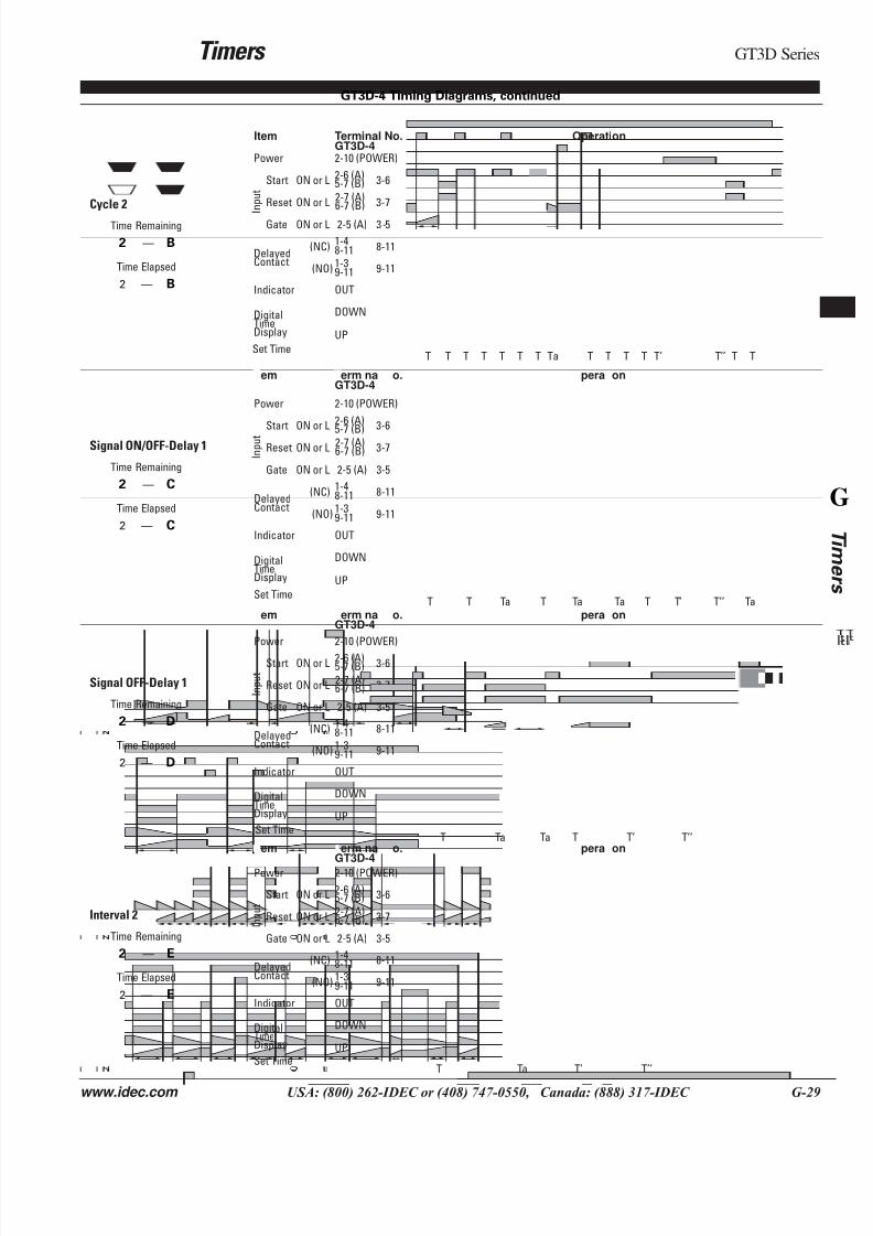
Cycle 2
Signal ON/OFF-Delay 1
Signal OFF-Delay 1
Interval 2
GT3D-4 Timing Diagrams, continued
2 B
B2 —
—
Time Remaining
Time Elapsed
Item
Power
Delayed
Indicator
Terminal No. Operation
2-10 (POWER)
8-11 8-11
9-11
UP
Contact
OUT
DOWNDigitalTimeDisplay
1-4
1-3
Set Time
GT3D-4
9-11
(NC)
(NO)
T Ta
2-6 (A)5-7 (B) 3-6ON or L
2-7 (A)6-7 (B) 3-7ON or L
2-5 (A) 3-5ON or L
Start
Reset
Gate
I n p u t
T T T T T T T T T T T’ T’’ T T
2 C
C2 —
—
Time Remaining
Time Elapsed
em
Power
Delayed
Indicator
erm na o. pera on
2-10 (POWER)
8-11 8-11
9-11
UP
Contact
OUT
DOWNDigitalTimeDisplay
1-4
1-3
Set Time
GT3D-4
9-11
(NC)
(NO)
2-6 (A)
5-7 (B)3-6ON or L
2-7 (A)6-7 (B) 3-7ON or L
2-5 (A) 3-5ON or L
Start
Reset
Gate
I n p u t
T TTa Ta T T’T Ta T’’ Ta
2 D
D2 —
—
Time Remaining
Time Elapsed
em
Power
Delayed
Indicator
erm na o. pera on
2-10 (POWER)
8-11 8-11
9-11
UP
Contact
OUT
DOWNDigitalTimeDisplay
1-4
1-3
Set Time
GT3D-4
9-11
(NC)
(NO)
2-6 (A)5-7 (B) 3-6ON or L
2-7 (A)6-7 (B) 3-7ON or L
2-5 (A) 3-5ON or L
Start
Reset
Gate
I n p u t
Ta Ta TT T’ T’’
2 E
E2 —
—
Time Remaining
Time Elapsed
em
Power
Delayed
Indicator
erm na o. pera on
2-10 (POWER)
8-11 8-11
9-11
UP
Contact
OUT
DOWNDigitalTimeDisplay
1-4
1-3
Set Time
GT3D-4
9-11
(NC)
(NO)
2-6 (A)5-7 (B) 3-6ON or L
2-7 (A)6-7 (B) 3-7ON or L
2-5 (A) 3-5ON or L
Start
Reset
Gate
I n p u t
Ta T’T T’’
7/28/2019 g Timers Gt3
http://slidepdf.com/reader/full/g-timers-gt3 17/41
GT3D Series Timers
G-30 www.idec.com USA: (800) 262-IDEC or (408) 747-0550, Canada: (888) 317-IDEC
G
Timers
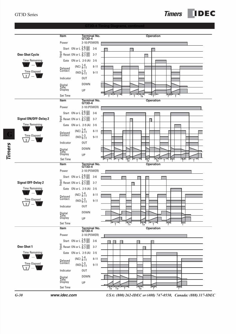
One-Shot Cycle
Signal ON/OFF-Delay 2
Signal OFF-Delay 2
One-Shot 1
GT3D-4 Timing Diagrams, continued
2 F
F2 —
—
Time Remaining
Time Elapsed
Item
Power
Delayed
Indicator
Terminal No. Operation
2-10 (POWER)
8-11 8-11
9-11
UP
Contact
OUT
DOWNDigitalTimeDisplay
1-4
1-3
Set Time
GT3D-4
9-11
(NC)
(NO)
2-6 (A)5-7 (B) 3-6ON or L
2-7 (A)6-7 (B) 3-7ON or L
2-5 (A) 3-5ON or L
Start
Reset
Gate
I n p u t
T TaT T’T T’’ T
3 A
A3 —
—
Time Remaining
Time Elapsed
Item
Power
Delayed
Indicator
Terminal No. Operation
2-10 (POWER)
8-11 8-11
9-11
UP
Contact
OUT
DOWNDigitalTimeDisplay
1-4
1-3
Set Time
GT3D-4
9-11
(NC)
(NO)
2-6 (A)5-7 (B) 3-6ON or L
2-7 (A)6-7 (B) 3-7ON or L
2-5 (A) 3-5ON or L
Start
Reset
Gate
I n p u t
TTaT T TaTa T T’ T’’ T
3 B
B3 —
—
Time Remaining
Time Elapsed
Item
Power
Delayed
Indicator
Terminal No. Operation
2-10 (POWER)
8-11 8-11
9-11
UP
Contact
OUT
DOWNDigitalTimeDisplay
1-4
1-3
Set Time
GT3D-4
9-11
(NC)
(NO)
2-6 (A)5-7 (B) 3-6ON or L
2-7 (A)6-7 (B) 3-7ON or L
2-5 (A) 3-5ON or L
Start
Reset
Gate
I n p u t
TaT Ta T T’ T’’
3 C
C3 —
—
Time Remaining
Time Elapsed
Item
Power
Delayed
Indicator
Terminal No. Operation
2-10 (POWER)
8-11 8-11
9-11
UP
Contact
OUT
DOWNDigitalTimeDisplay
1-4
1-3
Set Time
GT3D-4
9-11
(NC)
(NO)
2-6 (A)5-7 (B) 3-6ON or L
2-7 (A)6-7 (B) 3-7ON or L
2-5 (A) 3-5ON or L
Start
Reset
Gate
I n p u t
TaTa TaT T’ T’’
7/28/2019 g Timers Gt3
http://slidepdf.com/reader/full/g-timers-gt3 18/41
Timers GT3D Series
www.idec.com USA: (800) 262-IDEC or (408) 747-0550, Canada: (888) 317-IDEC G-31
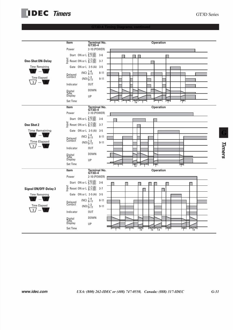
One-Shot ON-Delay
One Shot 2
Signal ON/OFF-Delay 3
GT3D-4 Timing Diagrams, continued
3 D
D3 —
—
Time Remaining
Time Elapsed
Item
Power
Delayed
Indicator
Terminal No. Operation
2-10 (POWER)
8-11 8-11
9-11
UP
Contact
OUT
DOWNDigitalTimeDisplay
1-4
1-3
Set Time
GT3D-4
9-11
(NC)
(NO)
2-6 (A)5-7 (B) 3-6ON or L
2-7 (A)6-7 (B) 3-7ON or L
2-5 (A) 3-5ON or L
Start
Reset
Gate
I n p u t
TT TTa T T’ T’’
3 E
E3 —
—
Time Remaining
Time Elapsed
Item
Power
Delayed
Indicator
Terminal No. Operation
2-10 (POWER)
8-11 8-11
9-11
UP
Contact
OUT
DOWNDigitalTimeDisplay
1-4
1-3
Set Time
GT3D-4
9-11
(NC)
(NO)
2-6 (A)5-7 (B) 3-6ON or L
2-7 (A)6-7 (B) 3-7ON or L
2-5 (A) 3-5ON or L
Start
Reset
Gate
I n p u t
T TTa T’ T’’
3 F
F3 —
—
Time Remaining
Time Elapsed
Item
Power
Delayed
Indicator
Terminal No. Operation
2-10 (POWER)
8-11 8-11
9-11
UP
Contact
OUT
DOWNDigitalTimeDisplay
1-4
1-3
Set Time
GT3D-4
9-11
(NC)
(NO)
2-6 (A)5-7 (B) 3-6ON or L
2-7 (A)6-7 (B) 3-7ON or L
2-5 (A) 3-5ON or L
Start
Reset
Gate
I n p u t
T T Ta T’ T’’ TaTaTa
7/28/2019 g Timers Gt3
http://slidepdf.com/reader/full/g-timers-gt3 19/41
GT3D Series Timers
G-32 www.idec.com USA: (800) 262-IDEC or (408) 747-0550, Canada: (888) 317-IDEC
G
Timers
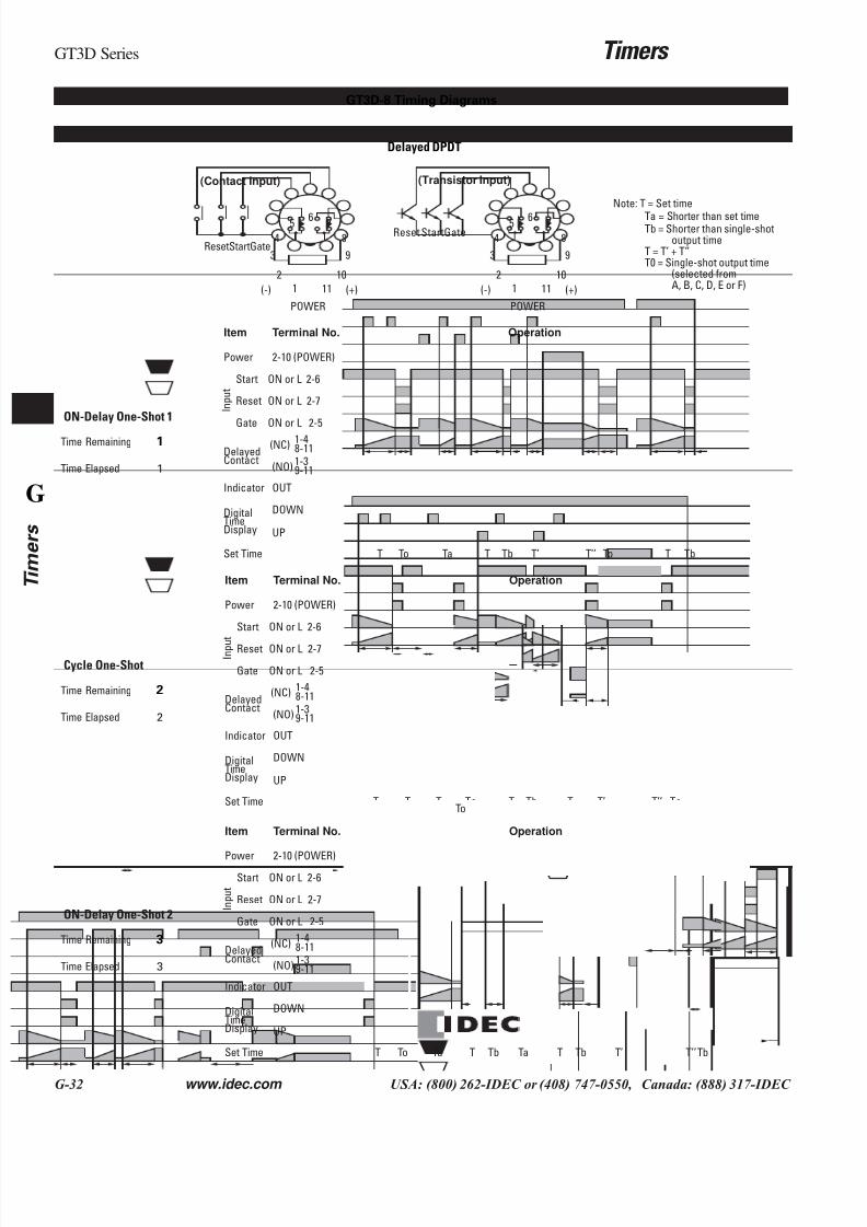
Delayed DPDT
ON-Delay One-Shot 1
Cycle One-Shot
ON-Delay One-Shot 2
GT3D-8 Timing Diagrams
Note: T = Set time
Ta = Shorter than set timeTb = Shorter than single-shot
output timeT = T’ + T”T0 = Single-shot output time
(selected fromA, B, C, D, E or F)
2
65 7
84
3
POWER
(+)(-)
9
10
111
ResetStartGate
2
65 7
84
3
POWER
(+)(-)
9
10
111
Reset StartGate
(Contact Input) (Transistor Input)
1
Time Remaining
Time Elapsed
1
Item
Power
Delayed
Indicator
Terminal No. Operation
2-10 (POWER)
8-11
9-11
UP
Contact
OUT
DOWNDigitalTimeDisplay
1-4
1-3
Set Time
(NC)
(NO)
2-6ON or L
2-7ON or L
2-5ON or L
Start
Reset
Gate
I n p u t
ToT Ta T T’’ ToTb T’ T Tb
2
Time Remaining
Time Elapsed
2
Item
Power
Delayed
Indicator
Terminal No. Operation
2-10 (POWER)
8-11
9-11
UP
Contact
OUT
DOWNDigitalTimeDisplay
1-4
1-3
Set Time
(NC)
(NO)
2-6ON or L
2-7ON or L
2-5ON or L
Start
Reset
Gate
I n p u
t
ToT
ToT T’Ta TbT T T’’T
ToTa
ToTo
3
Time Remaining
Time Elapsed
3
Item
Power
Delayed
Indicator
Terminal No. Operation
2-10 (POWER)
8-11
9-11
UP
Contact
OUT
DOWNDigitalTimeDisplay
1-4
1-3
Set Time
(NC)
(NO)
2-6ON or L
2-7ON or L
2-5ON or L
Start
Reset
Gate
I n p u t
ToT Ta T T TbTb Ta T’ TbT’’
7/28/2019 g Timers Gt3
http://slidepdf.com/reader/full/g-timers-gt3 20/41
Timers GT3D Series
www.idec.com USA: (800) 262-IDEC or (408) 747-0550, Canada: (888) 317-IDEC G-33
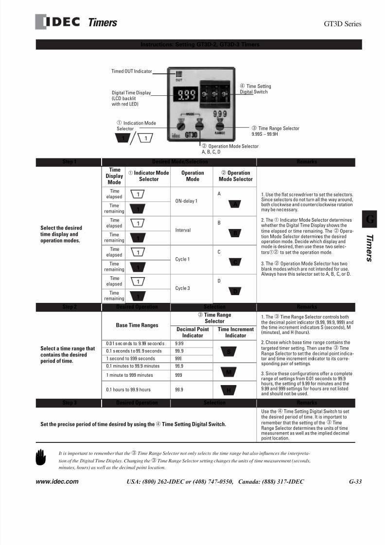
Step 1 Desired Mode/Selection Remarks
Select the desired time display andoperation modes.
TimeDisplayMode
➀ Indicator ModeSelector
OperationMode
➁ OperationMode Selector
1. Use the flat screwdriver to set the selectors.Since selectors do not turn all the way around,both clockwise and counterclockwise rotationmay be necessary.
2. The➀ Indicator Mode Selector determineswhether the Digital Time Display shows the time elapsed or time remaining. The➁ Opera- tion Mode Selector determines the desiredoperation mode. Decide which display andmode is desired, then use these two selec- tors➀➁ to set the operation mode.
3. The➁ Operation Mode Selector has twoblank modes which are not intended for use.Always have this selector set to A, B, C, or D.
Timeelapsed
ON-delay 1
A
Timeremaining
Timeelapsed
Interval
B
Timeremaining
Timeelapsed
Cycle 1
C
Timeremaining
Time
elapsed Cycle 3
D
Timeremaining
Step 2 Desired Operation Selection Remarks
Select a time range thatcontains the desiredperiod of time.
Base Time Ranges
➂ Time RangeSelector
1. The➂ Time Range Selector controls both the decimal point indicator (9.99, 99.9, 999) and the time increment indicators S (seconds), M(minutes), and H (hours).
2. Chose which base time range contains the targeted timer setting. Then use the➂ TimeRange Selector to set the decimal point indica- tor and time increment indicator to its corre-sponding pair of settings.
3. Since these configurations offer a completerange of settings from 0.01 seconds to 99.9hours, the setting of 9.99 for minutes and the9.99 and 999 settings for hours are not listedand should not be used.
Decimal PointIndicator
Time IncrementIndicator
0.01 seconds to 9.99 seconds 9.99
0.1 seconds to 99.9 seconds 99.9
1 second to 999 seconds 999
0.1 minutes to 99.9 minutes 99.9
1 minute to 999 minutes 999
0.1 hours to 99.9 hours 99.9
Step 3 Desired Operation Selection Remarks
Set the precise period of time desired by using the➃ Time Setting Digital Switch.
Use the➃ Time Setting Digital Switch to set the desired period of time. It is important toremember that the setting of the➂ TimeRange Selector determines the units of timemeasurement as well as the implied decimalpoint location.
Instructions: Setting GT3D-2, GT3D-3 Timers
Timed OUT Indicator
Digital Time Display(LCD backlitwith red LED)
➀ Indication ModeSelector
1 1
➃ Time SettingDigital Switch
➂ Time Range Selector9.99S – 99.9H
➁ Operation Mode SelectorA, B, C, D
1
A11
1
B11
1
C11
1
D11
SS
MM
HH
It is important to remember that the➂ Time Range Selector not only selects the time range but also influences the interpreta-
tion of the Digital Time Display. Changing the➂ Time Range Selector setting changes the units of time measurement (seconds,
minutes, hours) as well as the decimal point location.
7/28/2019 g Timers Gt3
http://slidepdf.com/reader/full/g-timers-gt3 21/41
GT3D Series Timers
G-34 www.idec.com USA: (800) 262-IDEC or (408) 747-0550, Canada: (888) 317-IDEC
G
Timers
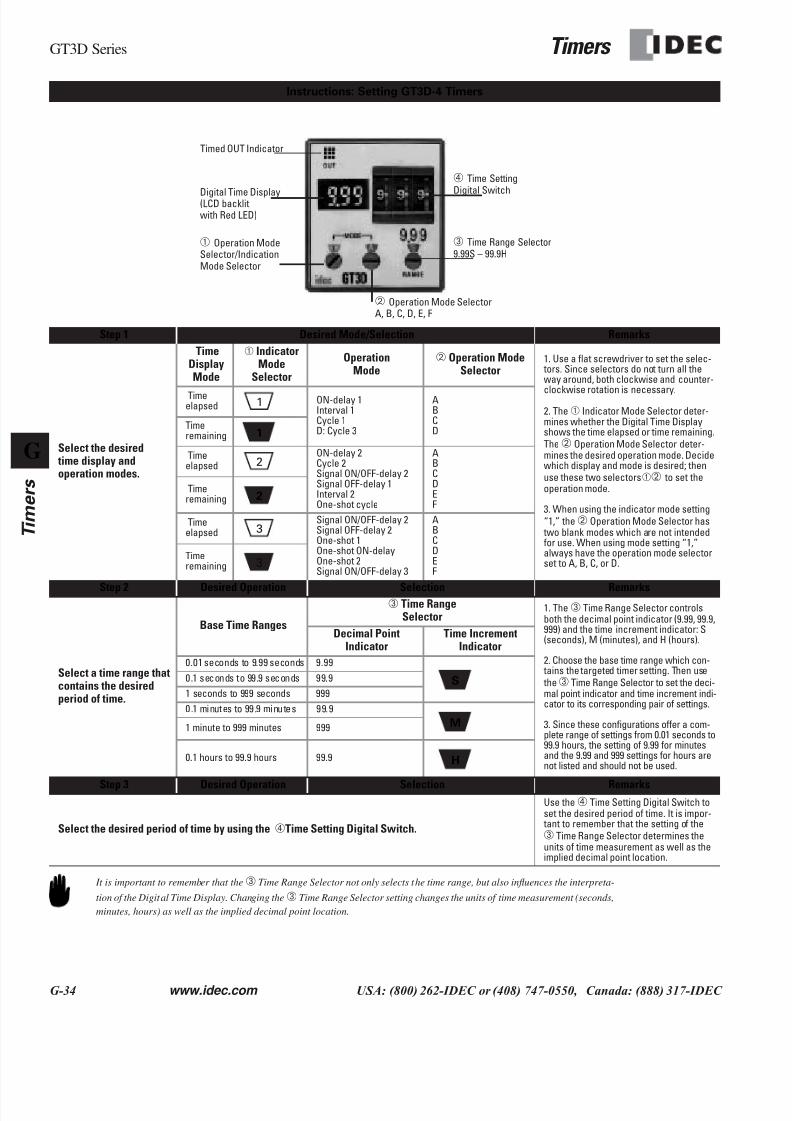
Step 1 Desired Mode/Selection Remarks
Select the desired time display andoperation modes.
TimeDisplayMode
➀ IndicatorMode
Selector
OperationMode
➁ Operation ModeSelector
1. Use a flat screwdriver to set the selec- tors. Since selectors do not turn all theway around, both clockwise and counter-
clockwise rotation is necessary.
2. The➀ Indicator Mode Selector deter-mines whether the Digital Time Displayshows the time elapsed or time remaining.The➁ Operation Mode Selector deter-mines the desired operation mode. Decidewhich display and mode is desired; thenuse these two selectors➀➁ to set theoperation mode.
3. When using the indicator mode setting“1,” the➁ Operation Mode Selector has two blank modes which are not intendedfor use. When using mode setting “1,”always have the operation mode selectorset to A, B, C, or D.
Timeelapsed
ON-delay 1Interval 1Cycle 1D: Cycle 3
ABCD
Timeremaining
Timeelapsed
ON-delay 2Cycle 2Signal ON/OFF-delay 2Signal OFF-delay 1Interval 2One-shot cycle
ABCDEF
Timeremaining
Timeelapsed
Signal ON/OFF-delay 2Signal OFF-delay 2One-shot 1One-shot ON-delayOne-shot 2Signal ON/OFF-delay 3
ABCDEF
Timeremaining
Step 2 Desired Operation Selection Remarks
Select a time range thatcontains the desiredperiod of time.
Base Time Ranges
➂ Time RangeSelector
1. The➂ Time Range Selector controlsboth the decimal point indicator (9.99, 99.9,999) and the time increment indicator: S(seconds), M (minutes), and H (hours).
2. Choose the base time range which con- tains the targeted timer setting. Then use the➂ Time Range Selector to set the deci-mal point indicator and time increment indi-cator to its corresponding pair of settings.
3. Since these configurations offer a com-plete range of settings from 0.01 seconds to99.9 hours, the setting of 9.99 for minutesand the 9.99 and 999 settings for hours arenot listed and should not be used.
Decimal PointIndicator
Time IncrementIndicator
0.01 seconds to 9.99 seconds 9.99
0.1 seconds to 99.9 seconds 99.9
1 seconds to 999 seconds 999
0.1 minutes to 99.9 minutes 99.9
1 minute to 999 minutes 999
0.1 hours to 99.9 hours 99.9
Step 3 Desired Operation Selection Remarks
Select the desired period of time by using the ➃Time Setting Digital Switch.
Use the➃ Time Setting Digital Switch toset the desired period of time. It is impor- tant to remember that the setting of the➂ Time Range Selector determines theunits of time measurement as well as theimplied decimal point location.
Instructions: Setting GT3D-4 Timers
Timed OUT Indicator
Digital Time Display(LCD backlitwith Red LED)
➃ Time SettingDigital Switch
➂ Time Range Selector9.99S – 99.9H
➁ Operation Mode SelectorA, B, C, D, E, F
➀ Operation ModeSelector/IndicationMode Selector
1
1
2
2
3
3
S
M
H
It is important to remember that the➂ Time Range Selector not only selects the time range, but also influences the interpreta-
tion of the Digital Time Display. Changing the➂ Time Range Selector setting changes the units of time measurement (seconds,
minutes, hours) as well as the implied decimal point location.
7/28/2019 g Timers Gt3
http://slidepdf.com/reader/full/g-timers-gt3 22/41
Timers GT3D Series
www.idec.com USA: (800) 262-IDEC or (408) 747-0550, Canada: (888) 317-IDEC G-35
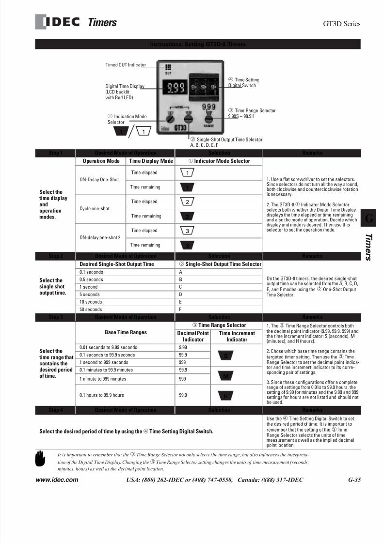
Step 1 Desired Mode of Operation Selection Remarks
Select the time displayandoperationmodes.
Operation Mode Time Display Mode ➀ Indicator Mode Selector
1. Use a flat screwdriver to set the selectors.Since selectors do not turn all the way around,
both clockwise and counterclockwise rotationis necessary.
2. The GT3D-8➀ Indicator Mode Selectorselects both whether the Digital Time Displaydisplays the time elapsed or time remainingand also the mode of operation. Decide whichdisplay and mode is desired. Then use thisselector to set the operation mode.
ON-Delay One-Shot
Time elapsed
Time remaining
Cycle one-shot
Time elapsed
Time remaining
ON-delay one-shot 2
Time elapsed
Time remaining
Step 2 Desired Mode of Operation Selection Remarks
Select the
single shotoutput time.
Desired Single-Shot Output Time ➁ Single-Shot Output Time Selector
On the GT3D-8 timers, the desired single-shot
output time can be selected from the A, B, C, D,E, and F modes using the➁ One-Shot OutputTime Selector.
0.1 seconds A
0.5 seconds B
1 second C
5 seconds D
10 seconds E
50 seconds F
Step 3 Desired Mode of Operation Selection Remarks
Select the time range thatcontains thedesired periodof time.
Base Time Ranges
➂ Time Range Selector 1. The➂ Time Range Selector controls both the decimal point indicator (9.99, 99.9, 999) and the time increment indicator: S (seconds), M(minutes), and H (hours).
2. Chose which base time range contains the targeted timer setting. Then use the➂ TimeRange Selector to set the decimal point indica- tor and time increment indicator to its corre-sponding pair of settings.
3. Since these configurations offer a completerange of settings from 0.01s to 99.9 hours, thesetting of 9.99 for minutes and the 9.99 and 999settings for hours are not listed and should notbe used.
Decimal PointIndicator
Time IncrementIndicator
0.01 seconds to 9.99 seconds 9.99
0.1 seconds to 99.9 seconds 99.9
1 second to 999 seconds 999
0.1 minutes to 99.9 minutes 99.9
1 minute to 999 minutes 999
0.1 hours to 99.9 hours 99.9
Step 4 Desired Mode of Operation Selection Remarks
Select the desired period of time by using the➃ Time Setting Digital Switch.
Use the➃ Time Setting Digital Switch to set the desired period of time. It is important toremember that the setting of the➂ TimeRange Selector selects the units of timemeasurement as well as the implied decimalpoint location.
Instructions: Setting GT3D-8 Timers
Timed OUT Indicator
Digital Time Display(LCD backlitwith Red LED)
➀ Indication ModeSelector
1 1
➃ Time SettingDigital Switch
➂ Time Range Selector9.99S – 99.9H
➁ Single-Shot Output Time SelectorA, B, C, D, E, F
1
1
2
2
3
3
S
M
H
It is important to remember that the➂ Time Range Selector not only selects the time range, but also influences the interpreta-
tion of the Digital Time Display. Changing the➂ Time Range Selector setting changes the units of time measurement (seconds,
minutes, hours) as well as the decimal point location.
7/28/2019 g Timers Gt3
http://slidepdf.com/reader/full/g-timers-gt3 23/41
GT3F Series Timers
G-36 www.idec.com USA: (800) 262-IDEC or (408) 747-0550, Canada: (888) 317-IDEC
G
Timers
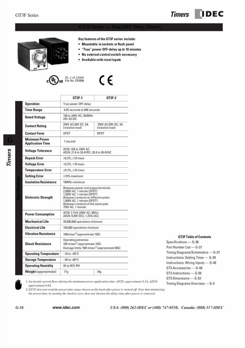
GT3F Series — True OFF Delay Timers
Key features of the GT3F series include:
• Mountable in sockets or flush panel
• “True” power OFF-delay up to 10 minutes
• No external control switch necessary
• Available with reset inputs
UL, c-uL ListedFile No. E55996
GT3F-1 GT3F-2
S p e c i f i c a t i
o n s
Operation True power OFF-delay
Time Range 0.05 seconds to 600 seconds
Rated Voltage 100 to 240V AC, 50/60Hz24V AC/DC
Contact Rating 250V AC/30V DC, 5A(resistive load)
250V AC/30V DC, 3A(resistive load)
Contact Form SPDT DPDT
Minimum PowerApplication Time
1 second
Voltage Tolerance AF20: 100 to 240V ACAD24: 21.6 to 26.4VDC, 20.4 to 26.4VAC
Repeat Error ±0.2%, ±10 msec
Voltage Error ±0.2%, ±10 msec
Temperature Error ±0.2%, ±10 msec
Setting Error ±10% maximum
Insulation Resistance 100MΩ minimum
Dielectric Strength
Between power and output terminals:2,000V AC, 1 minute (SPDT)1,500V AC, 1 minute (DPDT)Between contacts on different poles:1,000V AC, 1 minute (DPDT)Between contacts of the same pole:750V AC, 1 minute
Power Consumption AF20: 3.7VA (200V AC, 60Hz)AD24: 0.8W (DC), 1.2VA (AC)
Mechanical Life 20,000,000 operations minimum
Electrical Life 100,000 operations minimum
Vibration Resistance 100m/sec2 (approximate 10G)
Shock Resistance
Operating extremes:
100 m/sec2 (approximate 10G)Damage limits: 500 m/sec2 (approximate 50G)
Operating Temperature –10 to +50°C
Storage Temperature –30 to +80°C
Operating Humidity 45 to 85% RH
Weight (approximate) 77g 79g
1.An inrush current flows during the minimum power application time. AF20: approximate 0.3A, AD24:
approximate 0.6A
2.GT3F does not read the preset time range shown on the knob after power is turned off. Note that minimizing
the preset time, by turning the knob to zero, does not shorten the delay t ime after power is removed.
GT3F Table of Contents
Specifications — G-36
Part Number List — G-37
Timing Diagrams/Schematics — G-37
Instructions: Setting Timer — G-39
Instructions: Wiring Inputs — G-40
GT3 Accessories — G-48
GT3 Instructions — G-50
GT3 Dimensions — G-52
Timing Diagrams Overview — G-4
7/28/2019 g Timers Gt3
http://slidepdf.com/reader/full/g-timers-gt3 24/41
Timers GT3F Series
www.idec.com USA: (800) 262-IDEC or (408) 747-0550, Canada: (888) 317-IDEC G-37
Part Numbers: GT3F
Mode of Operation Rated Voltage CodeTime
RangeOutput Contact
OptionalInput
Complete Part Number
8-Pin 11-Pin
Power OFF-delayAF20: 100 to 240VAC (50/60Hz)
AD24: 24V AC/DC
0.05seconds to600seconds
250V AC, 5A,
30V DC, 5A(resistive load)
DelayedSPDT Reset
GT3F-1AF20 GT3F-1EAF20
GT3F-1AD24 GT3F-1EAD24
250V AC, 3A,30V DC, 3A(resistive load)
DelayedDPDT
None (8p)Reset(11p)
GT3F-2AF20 GT3F-2EAF20
GT3F-2AD24 GT3F-2EAD24
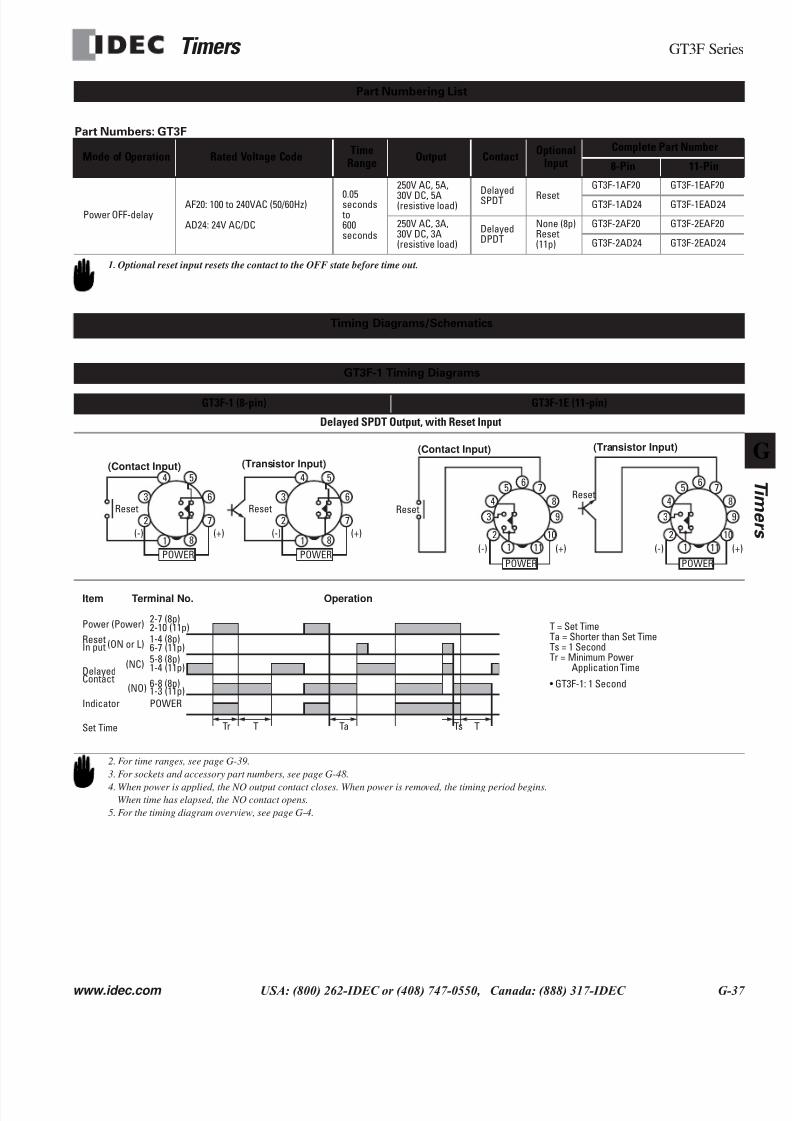
GT3F-1 (8-pin) GT3F-1E (11-pin)
Delayed SPDT Output, with Reset Input
Part Numbering List
1. Optional reset input resets the contact to the OFF state before time out.
Timing Diagrams/Schematics
GT3F-1 Timing Diagrams
1
2
6
5
7
8
4
3
POWER
(+)(-)
Reset
1
2
6
5
7
8
4
3
POWER
(+)(-)
Reset
(Contact Input) (Transistor Input)
2
65 7
84
3
POWER
(+)(-)
9
10
111
Reset
2
65 7
84
3
POWER
(+(-)
9
10
111
Reset
(Contact Input) (Transistor Input)
Item
Power
Reset
Delayed
Terminal No. Operation
2-7 (8p)2-10 (11p)(Power)
1-4 (8p)6-7 (11p)(ON or L)
5-8 (8p)1-4 (11p)(NC)
Set Time
In put
6-8 (8p)
POWER
Contact1-3 (11p)(NO)
Indicator
Tr T Ta Ts T
T = Set TimeTa = Shorter than Set TimeTs = 1 SecondTr = Minimum Power
Application Time
• GT3F-1: 1 Second
2. For time ranges, see page G-39.
3. For sockets and accessory part numbers, see page G-48.
4. When power is applied, the NO output contact closes. When power is removed, the timing period begins.When time has elapsed, the NO contact opens.
5. For the timing diagram overview, see page G-4.
7/28/2019 g Timers Gt3
http://slidepdf.com/reader/full/g-timers-gt3 25/41
GT3F Series Timers
G-38 www.idec.com USA: (800) 262-IDEC or (408) 747-0550, Canada: (888) 317-IDEC
G
Timers
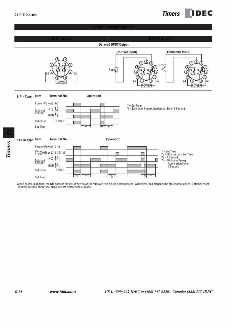
GT3F-2 (8-pin) GT3F-2E (11-pin)
Delayed DPDT Output
When power is applied, the NO contact closes. When power is removed, the timing period begins. When time has elapsed, the NO contact opens. Optional resetinput will return contacts to original state before time elapses.
GT3F-2 Timing Diagrams
1
2
6
7
8
3
POWER
(+)(-)
54
POWER
2
65 7
84
(+)(-)
10
111
Reset9
POWER
2
65 7
84
3
(+)(-)
10
111
9
Reset
3
(Contact Input) (Transistor Input)
Item
Power
Reset
Delayed
Terminal No. Operation
2-10(Power)
6-7 (11p)(ON or L)
1-48-11(NC)
Set Time
In put
1-3
POWER
Contact9-11(NO)
Indicator
Tr T Ta Ts T
11-Pin Type
Item
Power
Delayed
Terminal No. Operation
2-7(Power)
1-45-8(NC)
Set Time
1-3
POWER
Contact
6-8(NO)
Indicator
TrT T
8-Pin Type
T = Set TimeTr = Minimum Power Application Time: 1 Second
T = Set TimeTa = Shorter than Set TimeTs = 1 SecondTr = Minimum Power
Application Time:1 Second
7/28/2019 g Timers Gt3
http://slidepdf.com/reader/full/g-timers-gt3 26/41
Timers GT3F Series
www.idec.com USA: (800) 262-IDEC or (408) 747-0550, Canada: (888) 317-IDEC G-39
StepsDesired
OperationSelection Remarks
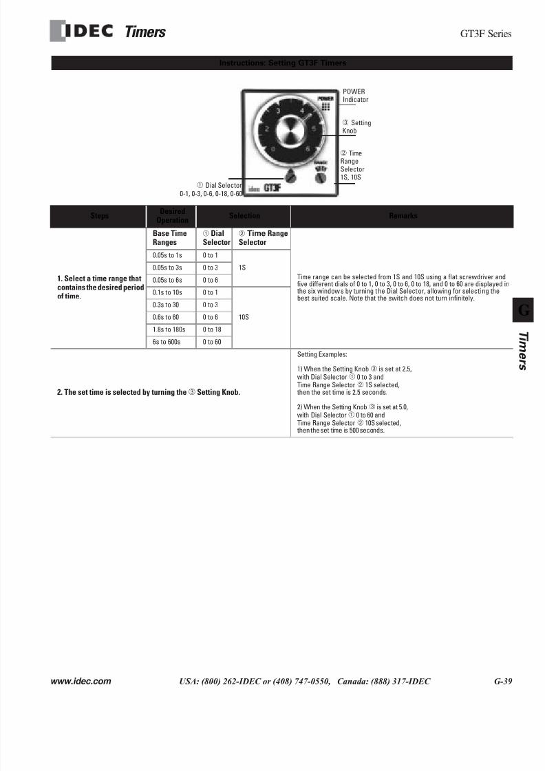
1. Select a time range thatcontains the desired periodof time.
Base TimeRanges
➀ DialSelector
➁ Time RangeSelector
Time range can be selected from 1S and 10S using a flat screwdriver andfive different dials of 0 to 1, 0 to 3, 0 to 6, 0 to 18, and 0 to 60 are displayed in the six windows by turning the Dial Selector, allowing for selecting thebest suited scale. Note that the switch does not turn infinitely.
0.05s to 1s 0 to 1
1S0.05s to 3s 0 to 30.05s to 6s 0 to 6
0.1s to 10s 0 to 1
10S
0.3s to 30 0 to 3
0.6s to 60 0 to 6
1.8s to 180s 0 to 18
6s to 600s 0 to 60
2. The set time is selected by turning the➂ Setting Knob.
Setting Examples:
1) When the Setting Knob➂ is set at 2.5,with Dial Selector➀ 0 to 3 andTime Range Selector➁ 1S selected, then the set time is 2.5 seconds.
2) When the Setting Knob➂ is set at 5.0,with Dial Selector➀ 0 to 60 andTime Range Selector➁ 10S selected, then the set time is 500 seconds.
Instructions: Setting GT3F Timers
POWERIndicator
➂ SettingKnob
➁ TimeRangeSelector1S, 10S
➀ Dial Selector0-1, 0-3, 0-6, 0-18, 0-60
7/28/2019 g Timers Gt3
http://slidepdf.com/reader/full/g-timers-gt3 27/41
GT3F Series Timers
G-40 www.idec.com USA: (800) 262-IDEC or (408) 747-0550, Canada: (888) 317-IDEC
G
Timers
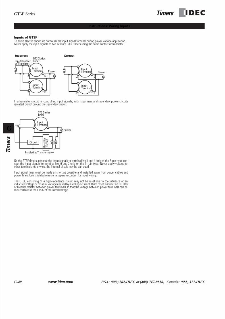
Inputs of GT3FTo avoid electric shock, do not touch the input signal terminal during power voltage application.Never apply the input signals to two or more GT3F timers using the same contact or transistor.
In a transistor circuit for controlling input signals, with its primary and secondary power circuitsisolated, do not ground the secondary circuit.
On the GT3F timers, connect the input signals to terminal No.1 and 4 only on the 8-pin type; con-nect the input signals to terminal No. 6 and 7 only on the 11-pin type. Never apply voltage to
other terminals; otherwise, the internal circuit may be damaged.Input signal lines must be made as short as possible and installed away from power cables andpower lines. Use shielded wires or a separate conduit for input wiring.
The GT3F, consisting of a high-impedance circuit, may not be reset due to the influence of aninductive voltage or residual voltage caused by a leakage current. If not reset, connect an RC filteror bleeder resistor between power terminals so that the voltage between power terminals can bereduced to less than 15% of the rated voltage.
Instructions: Wiring Inputs
~
InputTerminal
2
2
10
10
InputTerminal
Input Contactor Transistor
GT3 SeriesTimer
Power
Incorrect Correct
~
InputTerminal
2
2
10
10
InputTerminal
Power
~
InputTerminal
GT3 SeriesTimer
Power
R e c t i f i e r
C i r c u i t
Circuit
Insulating Transformer
7/28/2019 g Timers Gt3
http://slidepdf.com/reader/full/g-timers-gt3 28/41
Timers GT3S Series
www.idec.com USA: (800) 262-IDEC or (408) 747-0550, Canada: (888) 317-IDEC G-41
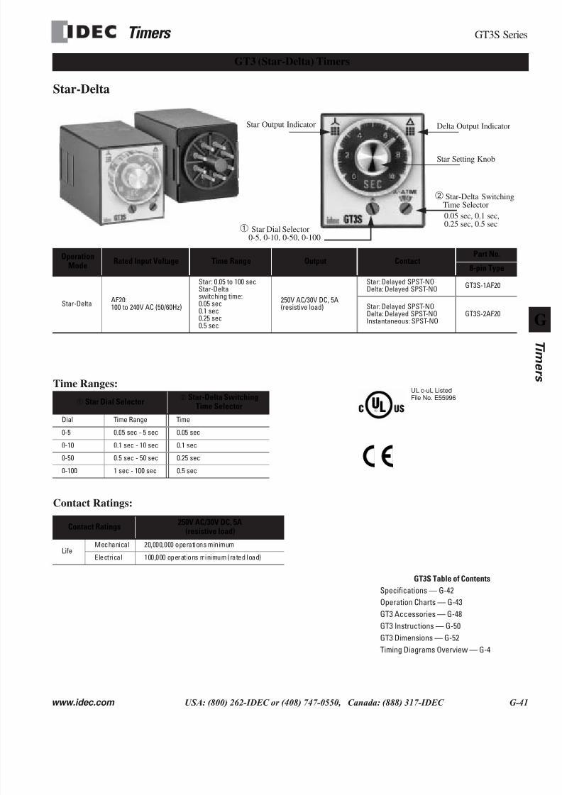
Star-Delta
Time Ranges:
Contact Ratings:
OperationMode
Rated Input Voltage Time Range Output ContactPart No.
8-pin Type
Star-DeltaAF20:100 to 240V AC (50/60Hz)
Star: 0.05 to 100 secStar-Deltaswitching time:0.05 sec0.1 sec0.25 sec0.5 sec
250V AC/30V DC, 5A(resistive load)
Star: Delayed SPST-NODelta: Delayed SPST-NO
GT3S-1AF20
Star: Delayed SPST-NODelta: Delayed SPST-NOInstantaneous: SPST-NO
GT3S-2AF20
➀ Star Dial Selector➁ Star-Delta Switching
Time Selector
Dial Time Range Time
0-5 0.05 sec - 5 sec 0.05 sec
0-10 0.1 sec - 10 sec 0.1 sec
0-50 0.5 sec - 50 sec 0.25 sec
0-100 1 sec - 100 sec 0.5 sec
Contact Ratings250V AC/30V DC, 5A
(resistive load)
LifeMechanical 20,000,000 operations minimum
Electrical 100,000 operations minimum (rated load)
GT3S Table of Contents
Specifications — G-42
Operation Charts — G-43
GT3 Accessories — G-48
GT3 Instructions — G-50
GT3 Dimensions — G-52
Timing Diagrams Overview — G-4
GT3 (Star-Delta) Timers
Delta Output Indicator
➁ Star-Delta SwitchingTime Selector
0.05 sec, 0.1 sec,0.25 sec, 0.5 sec
Star Output Indicator
➀ Star Dial Selector0-5, 0-10, 0-50, 0-100
Star Setting Knob
UL c-uL ListedFile No. E55996

7/28/2019 g Timers Gt3
http://slidepdf.com/reader/full/g-timers-gt3 29/41
GT3S Series Timers
G-42 www.idec.com USA: (800) 262-IDEC or (408) 747-0550, Canada: (888) 317-IDEC
G
Timers
Operation System Solid state CMOS circuitry
Operation Type Star-delta
Time RangeStar side: 0.05 to 100 secStar-delta switching time:0.05, 0.1, 0.25, 0.5 sec
Rated Operational Voltage 100 to 240V AC (50/60Hz)
Operating Temperature -10 to +50˚C
Storage Temperature -30 to +80˚C
Operating Humidity 45 to 85% RH
Voltage Tolerance 85 to 264V AC
Repeat Error ±0.2%, ±10 msec
Voltage Error ±0.2%, ±10 msec
Temperature Error ±0.2%, ±10 msec
Setting Error ±10% maximum
Reset Time 500 msec maximum
Insulation Resistance 100MΩ minimum
Dielectric StrengthBetween power and output terminals: 2,000V AC, 1 minuteBetween contacts of different poles: 2,000V AC, 1 minute
Between contacts of the same pole: 750V AC, 1 minuteVibration Resistance 100 m/sec2 (Approx. 10G)
Shock Resistance Operating extremes: 100m/sec2 (Approx. 10G)
Damage limits: 500m/sec2 (Approx. 50G)
PowerConsumption(Approx.)
TypeGT3S-1
3.0VA (100V AC, 60Hz),10.4VA (200V AC, 60Hz)
TypeGT3S-2
4.0VA (100V AC, 60Hz),12.0VA (200V AC, 60Hz)
General Specifications
7/28/2019 g Timers Gt3
http://slidepdf.com/reader/full/g-timers-gt3 30/41
Timers GT3S Series
www.idec.com USA: (800) 262-IDEC or (408) 747-0550, Canada: (888) 317-IDEC G-43
4
3
2
6
7
1 8
5
POWER
POWER
4
3
2
6
7
1 8
5
5
4
3
2
1 11
10
9
8
76
5
4
3
2
1 11
10
9
8
76
POWER
POWER
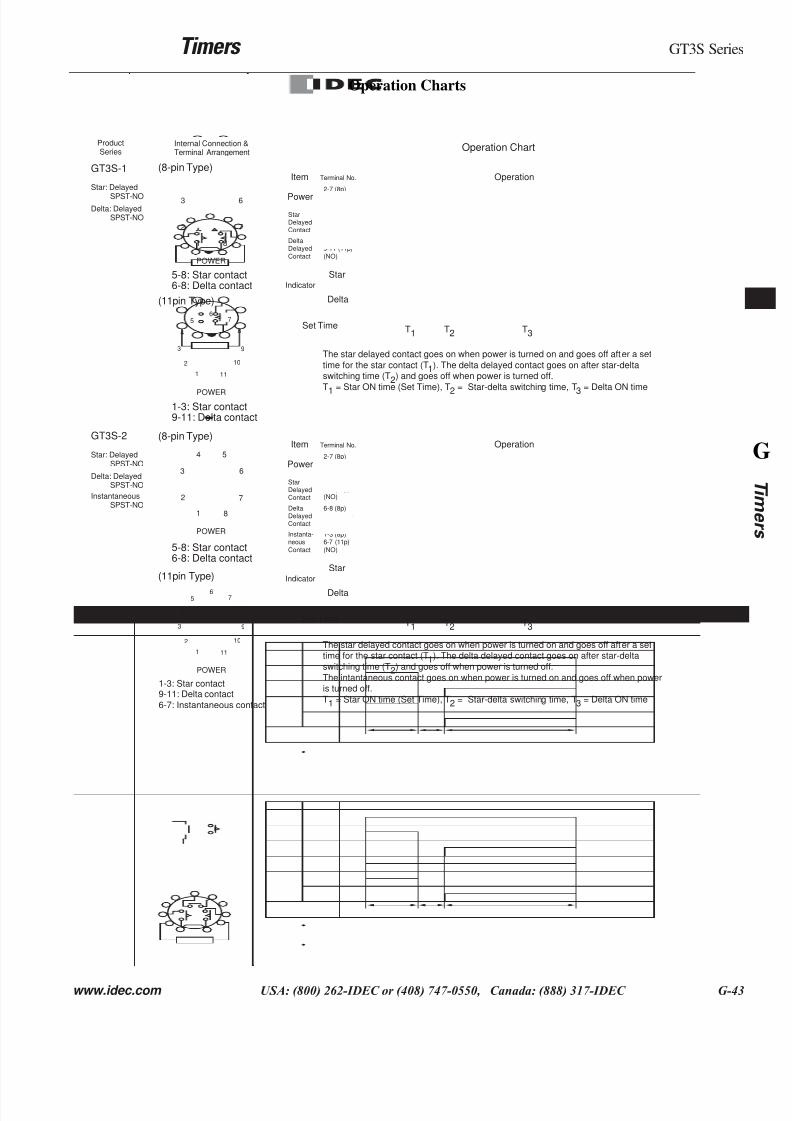
Item Terminal No. Operation
Power
2-7 (8p)
2-10 (11p)(POWER)
5-8 (8p)1-3 (11p)(NO)
6-8 (8p)9-11 (11p)
(NO)
Star
Delta
StarDelayedContact
DeltaDelayed
Contact
Indicator
Set Time T1 T2 T3
The star delayed contact goes on when power is turned on and goes off after a set
time for the star contact (T1). The delta delayed contact goes on after star-deltaswitching time (T2) and goes off when power is turned off.
T1
= Star ON time (Set Time), T2
= Star-delta switching time, T3
= Delta ON time
Item Terminal No. Operation
Power2-7 (8p)
2-10 (11p)(POWER)
5-8 (8p)1-3 (11p)(NO)
6-8 (8p)9-11 (11p)(NO)
Star
Delta
StarDelayedContact
DeltaDelayedContact
1-3 (8p)6-7 (11p)
(NO)
Instanta-neous
Contact
Indicator
Set Time T1 T2 T3
The star delayed contact goes on when power is turned on and goes off after a settime for the star contact (T1). The delta delayed contact goes on after star-delta
switching time (T2) and goes off when power is turned off.
The intantaneous contact goes on when power is turned on and goes off when poweris turned off.
T1 = Star ON time (Set Time), T2 = Star-delta switching time, T3 = Delta ON time
ProductSeries Operation ChartInternal Connection &
Terminal Arrangement
GT3S-1
Star: Delayed
SPST-NODelta: Delayed
SPST-NO
GT3S-2
Star: DelayedSPST-NO
Delta: DelayedSPST-NO
InstantaneousSPST-NO
(8-pin Type)
(11pin Type)
(8-pin Type)
(11pin Type)
5-8: Star contact6-8: Delta contact
1-3: Star contact9-11: Delta contact
5-8: Star contact6-8: Delta contact
1-3: Star contact9-11: Delta contact
6-7: Instantaneous contact
Operation Charts
7/28/2019 g Timers Gt3
http://slidepdf.com/reader/full/g-timers-gt3 31/41
GT3W Series Timers
G-44 www.idec.com USA: (800) 262-IDEC or (408) 747-0550, Canada: (888) 317-IDEC
G
Timers
c-uL Listed
UL ListedFile No.E55996
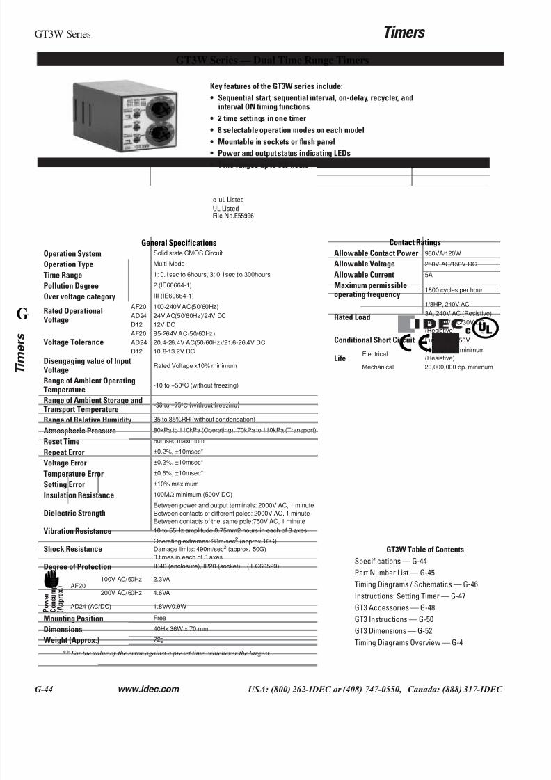
GT3W Series — Dual Time Range Timers
General Specifications
Operation System Solid state CMOS Circuit
Operation Type Multi-Mode
Time Range 1: 0.1sec to 6hours, 3: 0.1sec to 300hours
Pollution Degree 2 (IE60664-1)
Over voltage category III (IE60664-1)
Rated OperationalVoltage
AF20 100-240V AC(50/60Hz)
AD24 24V AC(50/60Hz)/24V DC
D12 12V DC
Voltage ToleranceAF20 85-264V AC(50/60Hz)
AD24 20.4-26.4V AC(50/60Hz)/21.6-26.4V DC
D12 10.8-13.2V DC
Disengaging value of InputVoltage
Rated Voltage x10% minimum
Range of Ambient OperatingTemperature
-10 to +50ºC (without freezing)
Range of Ambient Storage and
Transport Temperature-30 to +75ºC (without freezing)
Range of Relative Humidity 35 to 85%RH (without condensation)
Atmospheric Pressure 80kPa to 110kPa (Operating), 70kPa to 110kPa (Transport)
Reset Time 60msec maximum
Repeat Error ±0.2%, ±10msec*
Voltage Error ±0.2%, ±10msec*
Temperature Error ±0.6%, ±10msec*
Setting Error ±10% maximum
Insulation Resistance 100MΩ minimum (500V DC)
Dielectric StrengthBetween power and output terminals: 2000V AC, 1 minute
Between contacts of different poles: 2000V AC, 1 minute
Between contacts of the same pole:750V AC, 1 minute
Vibration Resistance 10 to 55Hz amplitude 0.75mm2 hours in each of 3 axes
Shock ResistanceOperating extremes: 98m/sec2 (approx.10G)
Damage limits: 490m/sec2 (approx. 50G)
3 times in each of 3 axes
Degree of Protection IP40 (enclosure), IP20 (socket) (IEC60529)
P o w e r
C o n s u m p t i o n
( A p p r o x . ) AF20
100V AC/60Hz 2.3VA
200V AC/60Hz 4.6VA
AD24 (AC/DC) 1.8VA/0.9W
Mounting Position Free
Dimensions 40Hx 36W x 70 mm
Weight (Approx.) 72g
Contact Ratings
Allowable Contact Power 960VA/120W
Allowable Voltage 250V AC/150V DC
Allowable Current 5A
Maximum permissibleoperating frequency
1800 cycles per hour
Rated Load
1/8HP, 240V AC
3A, 240V AC (Resistive)
5A, 120V AC/30V DC
(Resistive)
Conditional Short Circuit Fuse 5A, 250V
LifeElectrical
100,000 op. minimum
(Resistive)
Mechanical 20,000,000 op. minimum
** For the value of the error against a preset time, whichever the largest.
Key features of the GT3W series include:
• Sequential start, sequential interval, on-delay, recycler, andinterval ON timing functions
• 2 time settings in one timer
• 8 selectable operation modes on each model
• Mountable in sockets or flush panel
• Power and output status indicating LEDs
• Time ranges up to 300 hours
GT3W Table of Contents
Specifications — G-44
Part Number List — G-45
Timing Diagrams / Schematics — G-46
Instructions: Setting Timer — G-47
GT3 Accessories — G-48
GT3 Instructions — G-50
GT3 Dimensions — G-52
Timing Diagrams Overview — G-4
7/28/2019 g Timers Gt3
http://slidepdf.com/reader/full/g-timers-gt3 32/41
Timers GT3W Series
www.idec.com USA: (800) 262-IDEC or (408) 747-0550, Canada: (888) 317-IDEC G-45
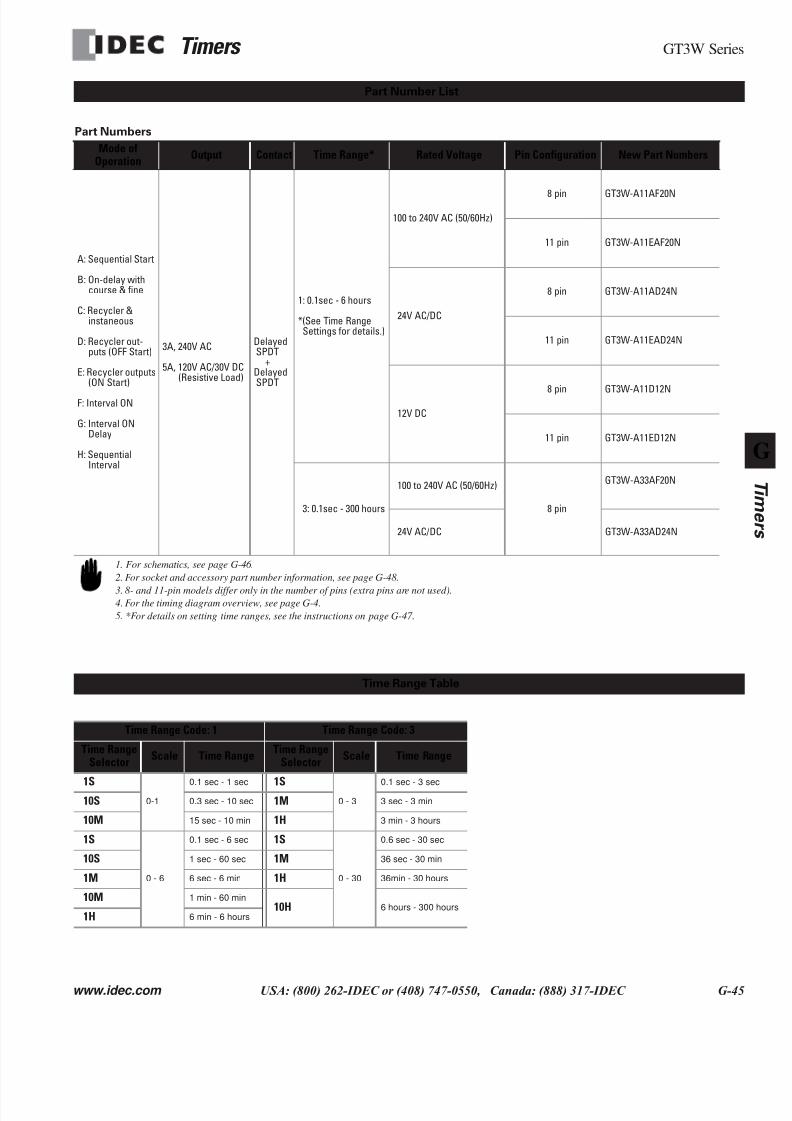
Part Numbers
Mode ofOperation
Output Contact Time Range* Rated Voltage Pin Configuration New Part Numbers
A: Sequential Start
B: On-delay withcourse & fine
C: Recycler &instaneous
D: Recycler out-puts (OFF Start)
E: Recycler outputs(ON Start)
F: Interval ON
G: Interval ONDelay
H: SequentialInterval
3A, 240V AC
5A, 120V AC/30V DC(Resistive Load)
DelayedSPDT
+DelayedSPDT
1: 0.1sec - 6 hours
*(See Time RangeSettings for details.)
100 to 240V AC (50/60Hz)
8 pin GT3W-A11AF20N
11 pin GT3W-A11EAF20N
24V AC/DC
8 pin GT3W-A11AD24N
11 pin GT3W-A11EAD24N
12V DC
8 pin GT3W-A11D12N
11 pin GT3W-A11ED12N
3: 0.1sec - 300 hours
100 to 240V AC (50/60Hz)
8 pin
GT3W-A33AF20N
24V AC/DC GT3W-A33AD24N
Time Range Code: 1 Time Range Code: 3
Time RangeSelector
Scale Time RangeTime Range
SelectorScale Time Range
1S0-1
0.1 sec - 1 sec 1S0 - 3
0.1 sec - 3 sec
10S 0.3 sec - 10 sec 1M 3 sec - 3 min
10M 15 sec - 10 min 1H 3 min - 3 hours
1S
0 - 6
0.1 sec - 6 sec 1S
0 - 30
0.6 sec - 30 sec
10S 1 sec - 60 sec 1M 36 sec - 30 min
1M 6 sec - 6 min 1H 36min - 30 hours
10M 1 min - 60 min10H 6 hours - 300 hours
1H 6 min - 6 hours
Part Number List
1. For schematics, see page G-46.
2. For socket and accessory part number information, see page G-48.
3. 8- and 11-pin models differ only in the number of pins (extra pins are not used).4. For the timing diagram overview, see page G-4.
5. *For details on setting time ranges, see the instructions on page G-47.
Time Range Table
7/28/2019 g Timers Gt3
http://slidepdf.com/reader/full/g-timers-gt3 33/41
GT3W Series Timers
G-46 www.idec.com USA: (800) 262-IDEC or (408) 747-0550, Canada: (888) 317-IDEC
G
Timers
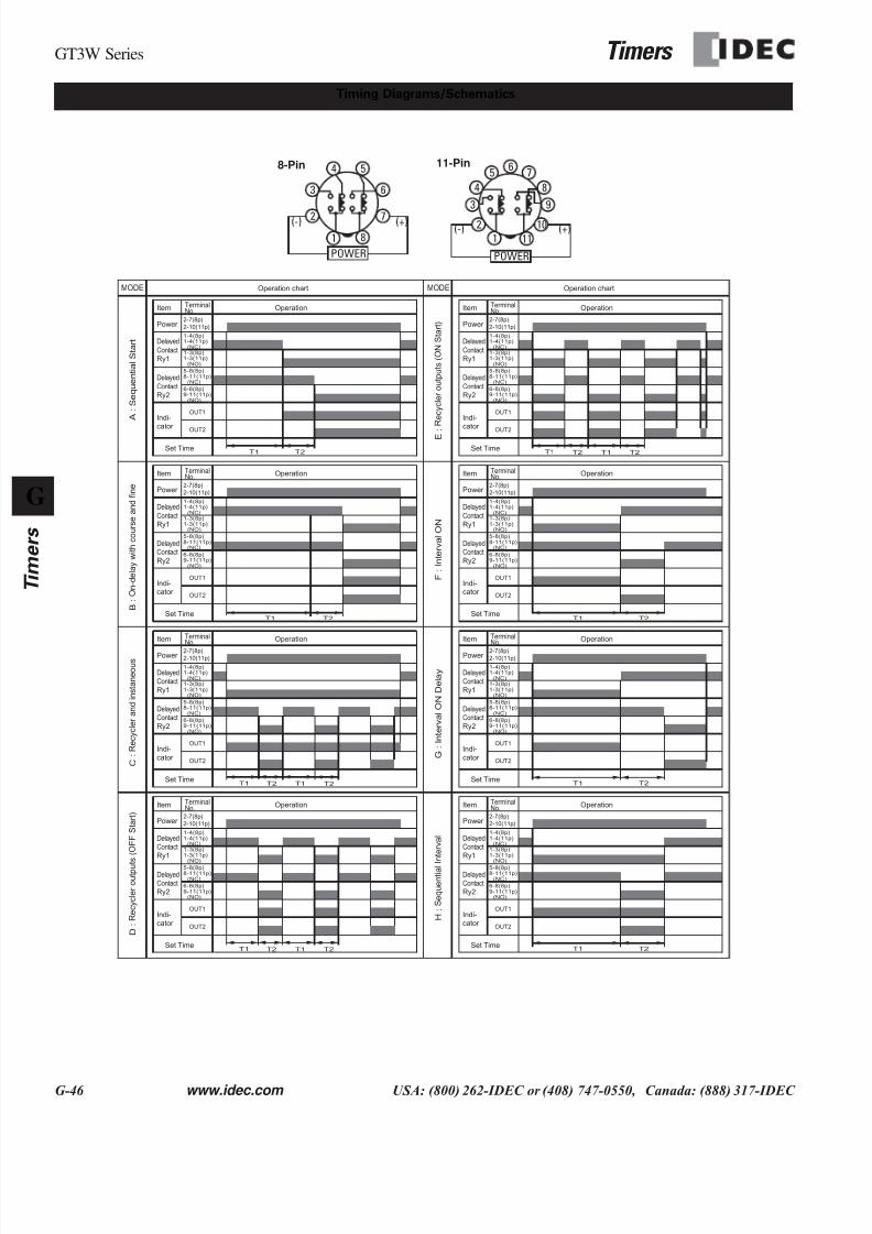
Timing Diagrams/Schematics
1
2
6
5
7
8
4
3
POWER
(+)(-) 2
65 7
84
3
POWER
(+)(-)
9
10
111
8-Pin 11-Pin
T1 T2 T1 T2
T1 T2
T1 T2
T1 T2
T1 T2
A
: S e q u e n t i a l S t a r t
B : O n - d e l a y w i t h c o u r s e a n d f i n e
C
: R e c y c l e r a n d i n s t a n e o u s
D
: R e c y c l e r o u t p u t s ( O F F S t a r t )
E : R e c y c l e r o u t p u t s ( O N
S t a r t )
F : I n t e r v a l O N
G :
I n t e r v a l O N
D e l a y
H
: S e q u e n t i a l I n t e r v a l
MODE MODE
Delayed
Contact
Ry2
Operation
Indi-cator
TerminalNo.Item
Power
Delayed
Contact
Ry1
5-8(8p)8-11(11p)(NC)
6-8(8p)9-11(11p)(NO)
2-7(8p)
2-10(11p)
1-4(8p)1-4(11p)(NC)
OUT1
1-3(8p)1-3(11p)(NO)
OUT2
Set Time
Delayed
Contact
Ry2
Operation
Indi-cator
TerminalNo.Item
Power
Delayed
Contact
Ry1
5-8(8p)8-11(11p)(NC)
6-8(8p)9-11(11p)(NO)
2-7(8p)
2-10(11p)
1-4(8p)1-4(11p)(NC)
OUT1
1-3(8p)1-3(11p)(NO)
OUT2
Set Time
Delayed
Contact
Ry2
Operation
Indi-cator
TerminalNo.Item
Power
Delayed
Contact
Ry1
5-8(8p)8-11(11p)(NC)
6-8(8p)9-11(11p)(NO)
2-7(8p)
2-10(11p)
1-4(8p)1-4(11p)(NC)
OUT1
1-3(8p)1-3(11p)(NO)
OUT2
Set Time
Delayed
Contact
Ry2
Operation
Indi-
cator
TerminalNo.Item
Power
Delayed
Contact
Ry1
5-8(8p)8-11(11p)(NC)
6-8(8p)9-11(11p)(NO)
2-7(8p)2-10(11p)
1-4(8p)1-4(11p)(NC)
OUT1
1-3(8p)1-3(11p)(NO)
OUT2
Set Time
Delayed
Contact
Ry2
Operation
Indi-cator
TerminalNo.Item
Power
Delayed
Contact
Ry1
5-8(8p)8-11(11p)(NC)
6-8(8p)9-11(11p)(NO)
2-7(8p)
2-10(11p)
1-4(8p)1-4(11p)(NC)
OUT1
1-3(8p)1-3(11p)(NO)
OUT2
Set Time
Delayed
Contact
Ry2
Operation
Indi-cator
TerminalNo.Item
Power
Delayed
Contact
Ry1
5-8(8p)8-11(11p)(NC)
6-8(8p)9-11(11p)(NO)
2-7(8p)
2-10(11p)
1-4(8p)1-4(11p)(NC)
OUT1
1-3(8p)1-3(11p)(NO)
OUT2
Set Time
Delayed
Contact
Ry2
Operation
Indi-
cator
TerminalNo.Item
Power
Delayed
Contact
Ry1
5-8(8p)8-11(11p)(NC)
6-8(8p)9-11(11p)(NO)
2-7(8p)2-10(11p)
1-4(8p)1-4(11p)(NC)
OUT1
1-3(8p)1-3(11p)(NO)
OUT2
Set Time
Delayed
Contact
Ry2
Operation
Indi-cator
TerminalNo.Item
Power
Delayed
Contact
Ry1
5-8(8p)8-11(11p)(NC)
6-8(8p)9-11(11p)(NO)
2-7(8p)
2-10(11p)
1-4(8p)1-4(11p)(NC)
OUT1
1-3(8p)1-3(11p)(NO)
OUT2
Set Time
Operation chart Operation chart
T1T2
T1 T2T1T2
T1 T2T1T2

7/28/2019 g Timers Gt3
http://slidepdf.com/reader/full/g-timers-gt3 34/41
Timers GT3W Series
www.idec.com USA: (800) 262-IDEC or (408) 747-0550, Canada: (888) 317-IDEC G-47
Instructions: Setting GT3W Timer
T2 Setting Knob
T1 Time RangeSelector
Operation ModeSelector
T2 Time Range
Selector
T1 Setting Knob
1. The switches should be securely turnedusing a flat screwdriver 4mm wide (maxi-mum). Note that incorrect setting may causemalfunction. The switches, which do not turn
infinitely, should not be turned beyond theirlimits.
2. Since changing the setting during timer oper-ation my cause malfunction, turn power offbefore changing.
Safety Precautions
Special expertise is required to use Electronic Timers.
• All Electronic Timer modules are manufactured under IDEC's rig-orous quality control system, but users must add a backup or fail
safe provision to the control system when using the Electronic
Timer in applications where heavy damage or personal injury may
occur should the Electronic Timer fail.
• Install the Electronic Timer according to instructions described in
this catalog.
• Make sure that the operating conditions are as described in the
specifications. If you are uncertain about the specifications, contact
IDEC in advance.
• In these directions, safety precautions are categorized in order of
importance to Warning and Caution.
Warning
Warning notices are used to emphasize that improper operation maycause sever personal injury or death.
• Turn power off to the Electronic timer before starting installation,
removal, Wiring, maintenance, and inspection on the Electronic
Timer.
• Failure to turn power off may cause electrical shocks or fire hazard.
• Emergency stop and interlocking circuits must be configured out-
side the Electronic timer. If such a circuit is configured inside the
Electronic Timer, failure of the Electronic timer may cause mal-
function of the control system, or an accident.
Caution
Caution notices are used where inattention might cause personalinjury or damage to equipment.
• The Electronic Timer is designed for installation in equipment. Do
not install the Electronic Timer outside equipment.
• Install the Electronic Timer in environments described in the speci-
fications. If the Electronic Timer is used in places where it will be
subjected to high-temperature, high-humidity, condensation, corro-
sive gases, excessive vibrations, or excessive shocks, then electrical
shocks, fire hazard, or malfunction could result.
• Use an IEC60127-approved fuse and circuit breaker on the power
and output line outside the Electronic Timer.
• Do not disassemble, repair, or modify the Electronic Timer.
• When disposing of the Electronic Timer, do so as industrial waste.
7/28/2019 g Timers Gt3
http://slidepdf.com/reader/full/g-timers-gt3 35/41
GT3 Series Accessories Timers
G-48 www.idec.com USA: (800) 262-IDEC or (408) 747-0550, Canada: (888) 317-IDEC
G
Timers
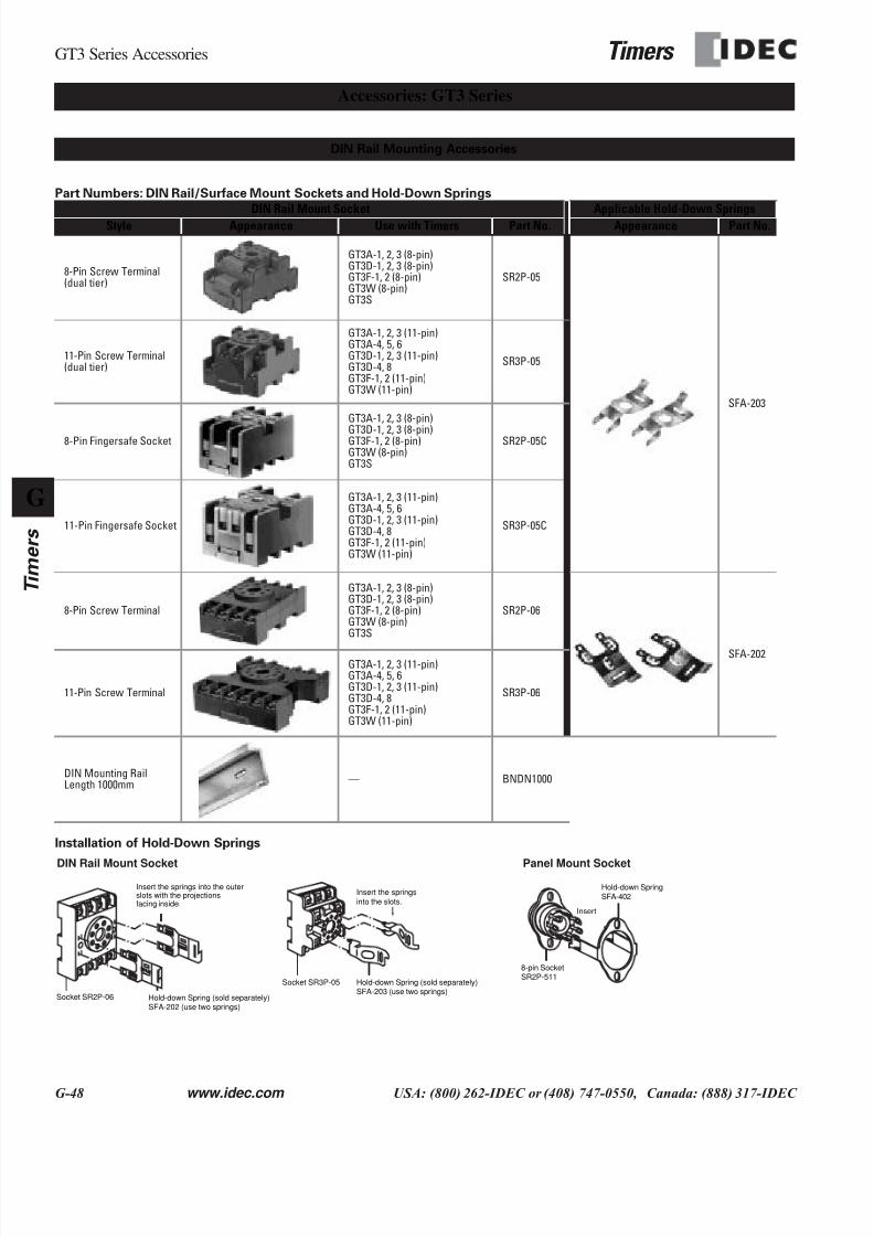
Part Numbers: DIN Rail/Surface Mount Sockets and Hold-Down Springs
Installation of Hold-Down Springs
DIN Rail Mount Socket Applicable Hold-Down Springs
Style Appearance Use with Timers Part No. Appearance Part No.
8-Pin Screw Terminal(dual tier)
GT3A-1, 2, 3 (8-pin)GT3D-1, 2, 3 (8-pin)GT3F-1, 2 (8-pin)GT3W (8-pin)GT3S
SR2P-05
SFA-203
11-Pin Screw Terminal(dual tier)
GT3A-1, 2, 3 (11-pin)GT3A-4, 5, 6GT3D-1, 2, 3 (11-pin)GT3D-4, 8GT3F-1, 2 (11-pin)GT3W (11-pin)
SR3P-05
8-Pin Fingersafe Socket
GT3A-1, 2, 3 (8-pin)
GT3D-1, 2, 3 (8-pin)GT3F-1, 2 (8-pin)GT3W (8-pin)GT3S
SR2P-05C
11-Pin Fingersafe Socket
GT3A-1, 2, 3 (11-pin)GT3A-4, 5, 6GT3D-1, 2, 3 (11-pin)GT3D-4, 8GT3F-1, 2 (11-pin)GT3W (11-pin)
SR3P-05C
8-Pin Screw Terminal
GT3A-1, 2, 3 (8-pin)GT3D-1, 2, 3 (8-pin)GT3F-1, 2 (8-pin)GT3W (8-pin)GT3S
SR2P-06
SFA-202
11-Pin Screw Terminal
GT3A-1, 2, 3 (11-pin)GT3A-4, 5, 6GT3D-1, 2, 3 (11-pin)GT3D-4, 8GT3F-1, 2 (11-pin)GT3W (11-pin)
SR3P-06
DIN Mounting RailLength 1000mm
— BNDN1000
Accessories: GT3 Series
DIN Rail Mounting Accessories
DIN Rail Mount Socket Panel Mount Socket
Socket SR2P-06 Hold-down Spring (sold separately)SFA-202 (use two springs)
Insert the springs into the outerslots with the projectionsfacing inside.
Socket SR3P-05
Insert the springs
into the slots.
Hold-down Spring (sold separately)SFA-203 (use two springs)
8-pin SocketSR2P-511
Hold-down Spring
SFA-402
Insert
7/28/2019 g Timers Gt3
http://slidepdf.com/reader/full/g-timers-gt3 36/41
Timers GT3 Series Accessories
www.idec.com USA: (800) 262-IDEC or (408) 747-0550, Canada: (888) 317-IDEC G-49
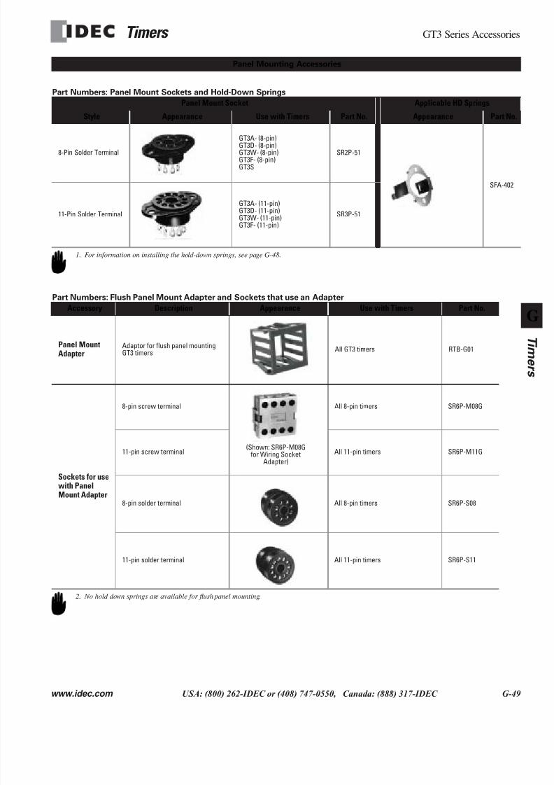
Part Numbers: Panel Mount Sockets and Hold-Down Springs
Part Numbers: Flush Panel Mount Adapter and Sockets that use an Adapter
Panel Mount Socket Applicable HD Springs
Style Appearance Use with Timers Part No. Appearance Part No.
8-Pin Solder Terminal
GT3A- (8-pin)GT3D- (8-pin)GT3W- (8-pin)GT3F- (8-pin)GT3S
SR2P-51
SFA-402
11-Pin Solder Terminal
GT3A- (11-pin)GT3D- (11-pin)GT3W- (11-pin)GT3F- (11-pin)
SR3P-51
Accessory Description Appearance Use with Timers Part No.
Panel MountAdapter
Adaptor for flush panel mountingGT3 timers
All GT3 timers RTB-G01
Sockets for usewith PanelMount Adapter
8-pin screw terminal All 8-pin timers SR6P-M08G
11-pin screw terminal All 11-pin timers SR6P-M11G
8-pin solder terminal All 8-pin timers SR6P-S08
11-pin solder terminal All 11-pin timers SR6P-S11
1. For information on installing the hold-down springs, see page G-48.
Panel Mounting Accessories
(Shown: SR6P-M08Gfor Wiring Socket
Adapter)
2. No hold down springs are available for flush panel mounting.
7/28/2019 g Timers Gt3
http://slidepdf.com/reader/full/g-timers-gt3 37/41
GT3 Series Instructions Timers
G-50 www.idec.com USA: (800) 262-IDEC or (408) 747-0550, Canada: (888) 317-IDEC
G
Timers
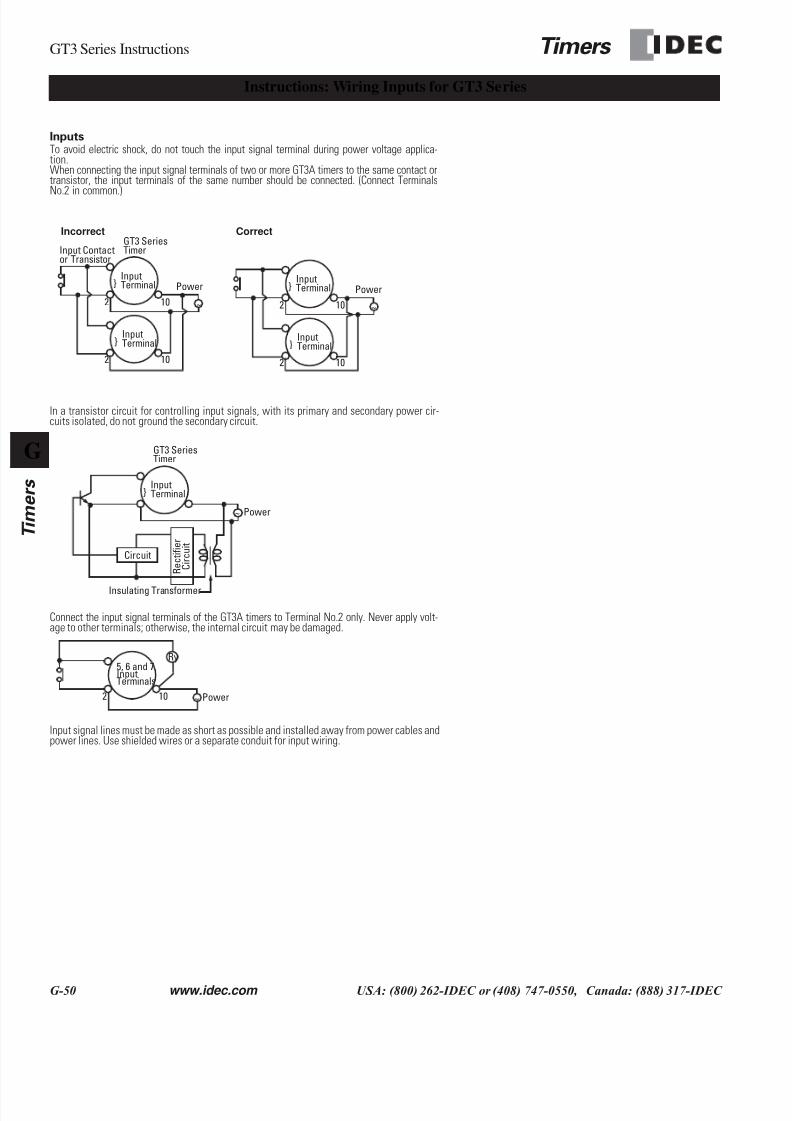
InputsTo avoid electric shock, do not touch the input signal terminal during power voltage applica-tion.When connecting the input signal terminals of two or more GT3A timers to the same contact ortransistor, the input terminals of the same number should be connected. (Connect Terminals
No.2 in common.)
In a transistor circuit for controlling input signals, with its primary and secondary power cir-cuits isolated, do not ground the secondary circuit.
Connect the input signal terminals of the GT3A timers to Terminal No.2 only. Never apply volt-age to other terminals; otherwise, the internal circuit may be damaged.
Input signal lines must be made as short as possible and installed away from power cables andpower lines. Use shielded wires or a separate conduit for input wiring.
Instructions: Wiring Inputs for GT3 Series
~
InputTerminal
2
2
10
10
InputTerminal
Input Contactor Transistor
GT3 SeriesTimer
Power
Incorrect Correct
~
InputTerminal
2
2
10
10
InputTerminal
Power
~
InputTerminal
GT3 SeriesTimer
Power
R e c t i f i e r
C i r c u i t
Circuit
Insulating Transformer
~2 10 Power
5, 6 and 7InputTerminals
Ry
7/28/2019 g Timers Gt3
http://slidepdf.com/reader/full/g-timers-gt3 38/41
Timers GT3 Series Instructions
www.idec.com USA: (800) 262-IDEC or (408) 747-0550, Canada: (888) 317-IDEC G-51
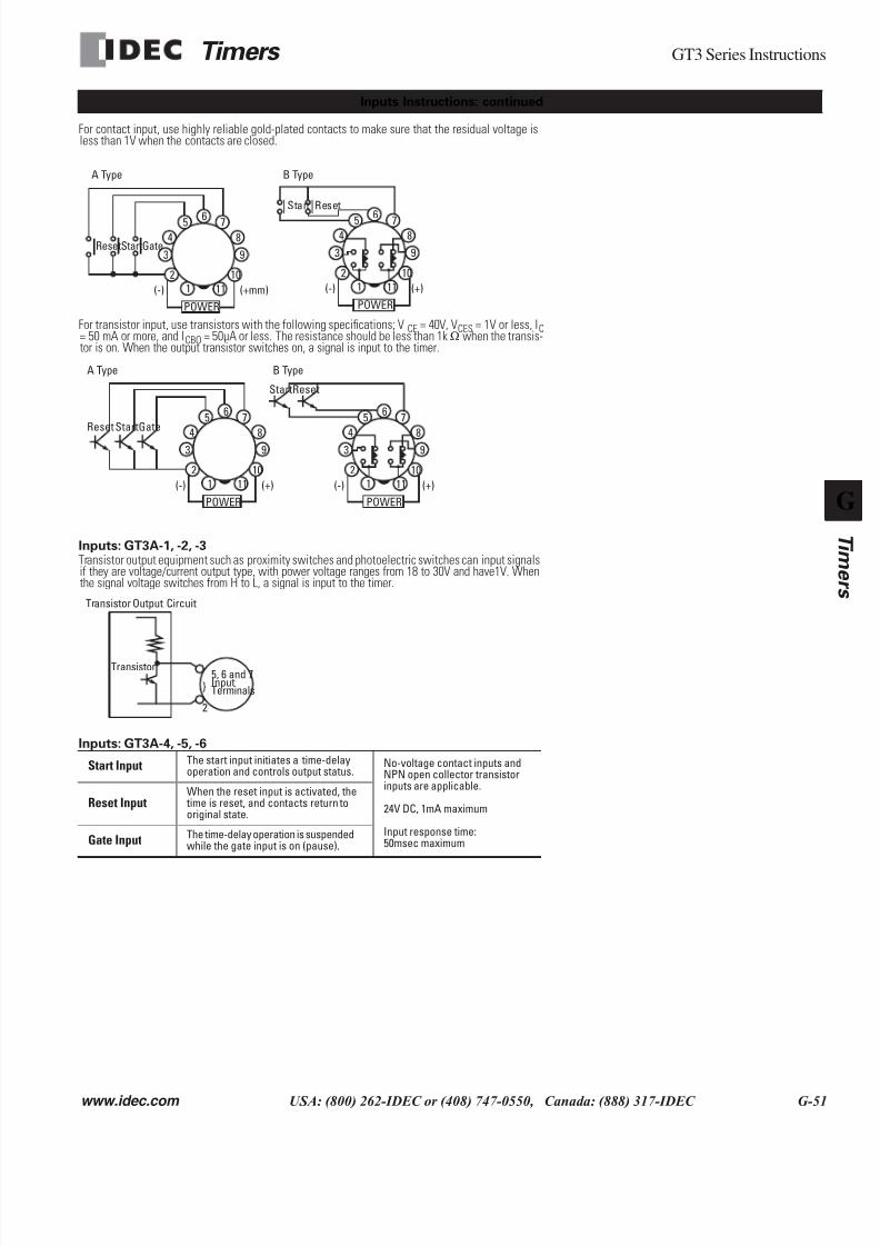
For contact input, use highly reliable gold-plated contacts to make sure that the residual voltage isless than 1V when the contacts are closed.
For transistor input, use transistors with the following specifications; VCE = 40V, VCES = 1V or less, IC= 50 mA or more, and ICBO = 50µA or less. The resistance should be less than 1kΩ when the transis-tor is on. When the output transistor switches on, a signal is input to the timer.
Inputs: GT3A-1, -2, -3Transistor output equipment such as proximity switches and photoelectric switches can input signalsif they are voltage/current output type, with power voltage ranges from 18 to 30V and have1V. Whenthe signal voltage switches from H to L, a signal is input to the timer.
Inputs: GT3A-4, -5, -6
Start Input The start input initiates a time-delayoperation and controls output status.
No-voltage contact inputs andNPN open collector transistorinputs are applicable.
24V DC, 1mA maximum
Input response time:50msec maximum
Reset InputWhen the reset input is activated, the time is reset, and contacts return tooriginal state.
Gate Input The time-delay operation is suspendedwhile the gate input is on (pause).
Inputs Instructions: continued
2
65 7
84
3
POWER
(+mm)(-)
9
10
111
ResetStartGate
2
65 784
3
POWER
(+)(-)
9
10
111
Start Reset
A Type B Type
2
65 7
843
POWER
(+)(-)
9
10
111
Reset StartGate
2
65 7
843
POWER
(+)(-)
9
10
111
StartReset
A Type B Type
5, 6 and 7InputTerminals
2
Transistor
Transistor Output Circuit

7/28/2019 g Timers Gt3
http://slidepdf.com/reader/full/g-timers-gt3 39/41
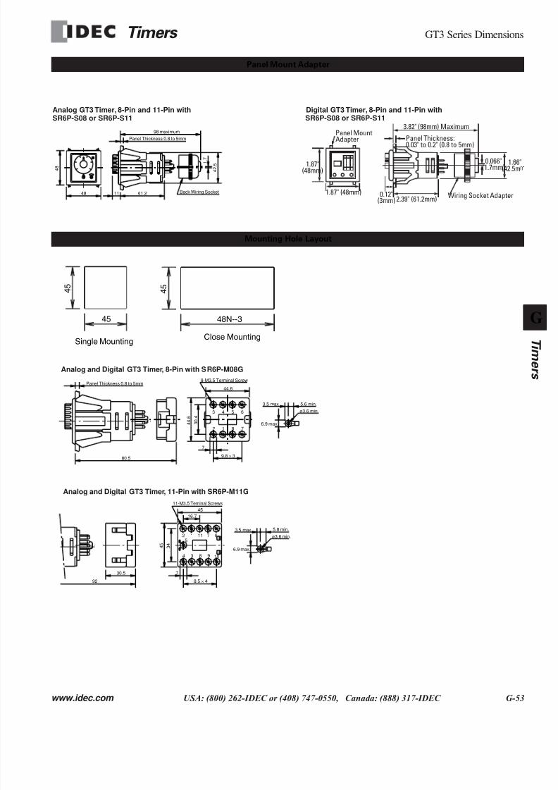
7/28/2019 g Timers Gt3
http://slidepdf.com/reader/full/g-timers-gt3 40/41
Timers GT3 Series Dimensions
www.idec.com USA: (800) 262-IDEC or (408) 747-0550, Canada: (888) 317-IDEC G-53
Panel Mount Adapter
1.87"(48mm)
1.87" (48mm)
Panel MountAdapter
2.39" (61.2mm)0.12"
(3mm)
Panel Thickness:0.03" to 0.2" (0.8 to 5mm)
0.066"(1.7mm)
3.82" (98mm) Maximum
Wiring Socket Adapter
1.66"(42.5m
Analog GT3 Timer, 8-Pin and 11-Pin with Digital GT3 Timer, 8-Pin and 11-Pin withSR6P-S08 or SR6P-S11 SR6P-S08 or SR6P-S11
Back Wiring Socket
1 .
7
48
4 8
11 61.2
Panel Thickness 0.8 to 5mm
4 2 .
5
98 maximum
Mounting Hole Layout
Analog and Digital GT3 Timer, 8-Pin with SR6P-M08G
Analog and Digital GT3 Timer, 11-Pin with SR6P-M11G
ø3.6 min.
8-M3.5 Terminal Screw
2 1 8 7
3 4 5 6
6.9 max. 3 0 .
4
4 4 .
6
Panel Thickness 0.8 to 5mm
80.5
7
9.8 × 3
44.6
3.5 max. 5.6 min.
ø3.6 min.
11-M3.5 Teminal Screws
6.9 max.
92
4 3 8 9 10
2 115
1 7 6
3.5 max. 5.8 min.
30.5 7
8.5 × 4
16.7
45
3 4
4 5
Close MountingSingle Mounting
45
4 5
4 5
48N--3
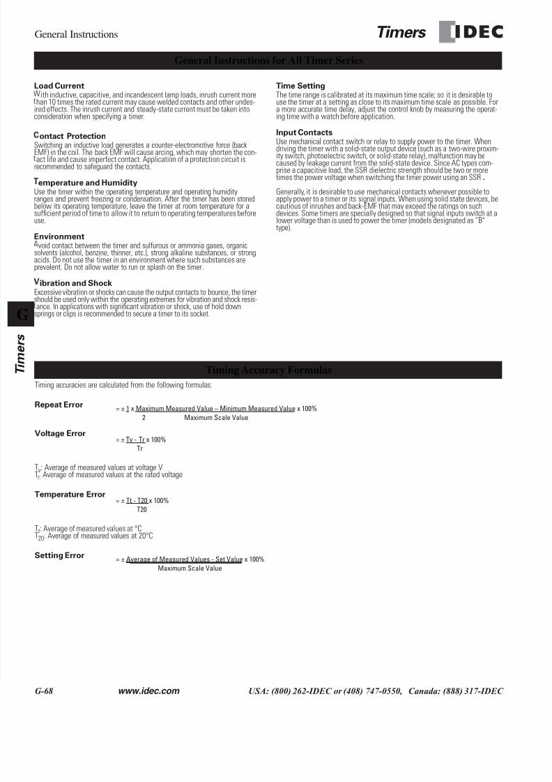
7/28/2019 g Timers Gt3
http://slidepdf.com/reader/full/g-timers-gt3 41/41
General Instructions Timers
G
Timers
Timing accuracies are calculated from the following formulas:
Repeat Error
Voltage Error
Tv: Average of measured values at voltage VTr: Average of measured values at the rated voltage
Temperature Error
Tt: Average of measured values at °CT20: Average of measured values at 20°C
Setting Error
General Instructions for All Timer Series
Load Currentith inductive, capacitive, and incandescent lamp loads, inrush current more
han 10 times the rated current may cause welded contacts and other undes-ired effects. The inrush current and steady-state current must be taken intoconsideration when specifying a timer.
ontact ProtectionSwitching an inductive load generates a counter-electromotive force (backEMF) in the coil. The back EMF will cause arcing, which may shorten the con-act life and cause imperfect contact. Application of a protection circuit is
recommended to safeguard the contacts.
emperature and HumidityUse the timer within the operating temperature and operating humidityranges and prevent freezing or condensation. After the timer has been storedbelow its operating temperature, leave the timer at room temperature for asufficient period of time to allow it to return to operating temperatures beforeuse.
Environmentvoid contact between the timer and sulfurous or ammonia gases, organic
solvents (alcohol, benzine, thinner, etc.), strong alkaline substances, or strongacids. Do not use the timer in an environment where such substances areprevalent. Do not allow water to run or splash on the timer.
ibration and ShockExcessive vibration or shocks can cause the output contacts to bounce, the timershould be used only within the operating extremes for vibration and shock resis-ance. In applications with significant vibration or shock, use of hold down
springs or clips is recommended to secure a timer to its socket.
Time SettingThe time range is calibrated at its maximum time scale; so it is desirable touse the timer at a setting as close to its maximum time scale as possible. Fora more accurate time delay, adjust the control knob by measuring the operat-ing time with a watch before application.
Input ContactsUse mechanical contact switch or relay to supply power to the timer. Whendriving the timer with a solid-state output device (such as a two-wire proxim-ity switch, photoelectric switch, or solid-state relay), malfunction may becaused by leakage current from the solid-state device. Since AC types com-prise a capacitive load, the SSR dielectric strength should be two or moretimes the power voltage when switching the timer power using an SSR.
Generally, it is desirable to use mechanical contacts whenever possible toapply power to a timer or its signal inputs. When using solid state devices, becautious of inrushes and back-EMF that may exceed the ratings on suchdevices. Some timers are specially designed so that signal inputs switch at alower voltage than is used to power the timer (models designated as “B"type).
Timing Accuracy Formulas
= ± 1 x Maximum Measured Value – Minimum Measured Value x 100%Maximum Scale Value2
= ± Tv - Tr x 100%
Tr
= ± Tt - T20 x 100%
T20
= ± Average of Measured Values - Set Value x 100%
Maximum Scale Value