g w s - cmdg.com.au · g w finished footpath level trench gas main (50 dia) additional trench width...
TRANSCRIPT

W
G
FINISHED FOOTPATH LEVEL
Tre
nch
Ga
s M
ain
(5
0 d
ia
)
Additional trench w
idth w
hen required
for telecom
munication pits
Ele
ctrica
l C
ab
le
s
Extra cover required for
high voltage
Telecommunication service cable pits,
electrical service cable pits and above
ground electrical low voltage pillars to
alternate with water stop tap locations at
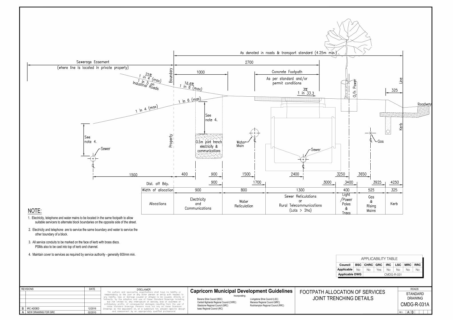
property boundaries.
1. For electrical and telecommunication notes, refer to relevant Authority.
Low voltage cable to be provided in conduit if required by Ergon Energy.3.
4. Future excavation areas must be clear of all other services.
Dimensions in millimetres and indicate clean trench widths.5.
6. Depth of cover to services under roadways shall be increased 150mm
and measured from the lip of design kerb and channel.
Minimum 75mm depth of sand bedding shall surround water main.7.
Lo
ca
l
Te
le
co
mm
un
ica
tio
n
co
nd
uit
2. All warning tape to be placed at nominal 300mm above any conduit.
Wa
te
r M
ain
Warning Tape
S
Warning Tape
DETAILS ARE INDICATIVE ONLY. REFER TO THE
RELEVANT UTILITY AUTHORITY FOR DESIGN
AND CONSTRUCTION SPECIFICATIONS.
Se
we
r M
ain
APPLICABILITY TABLE
Council BSC CHRC GRC IRC LSC MRC RRC
Applicable Yes Yes No Yes Yes Yes Yes
Applicable DWG CMDG-R-031AAlternative alignments to be negotiated with relevant authority and to 8.
provide adequate clearances to other services.
APPLICABILITY TABLE
Council BSC CHRC GRC IRC LSC MRC RRC
Applicable No No Yes No No No No
Applicable DWG CMDG-R-031
APPLICABILITY TABLE
Council BSC CHRC GRC IRC LSC MRC RRC
Applicable Yes Yes No Yes Yes Yes Yes
Applicable DWG CMDG-R-040A
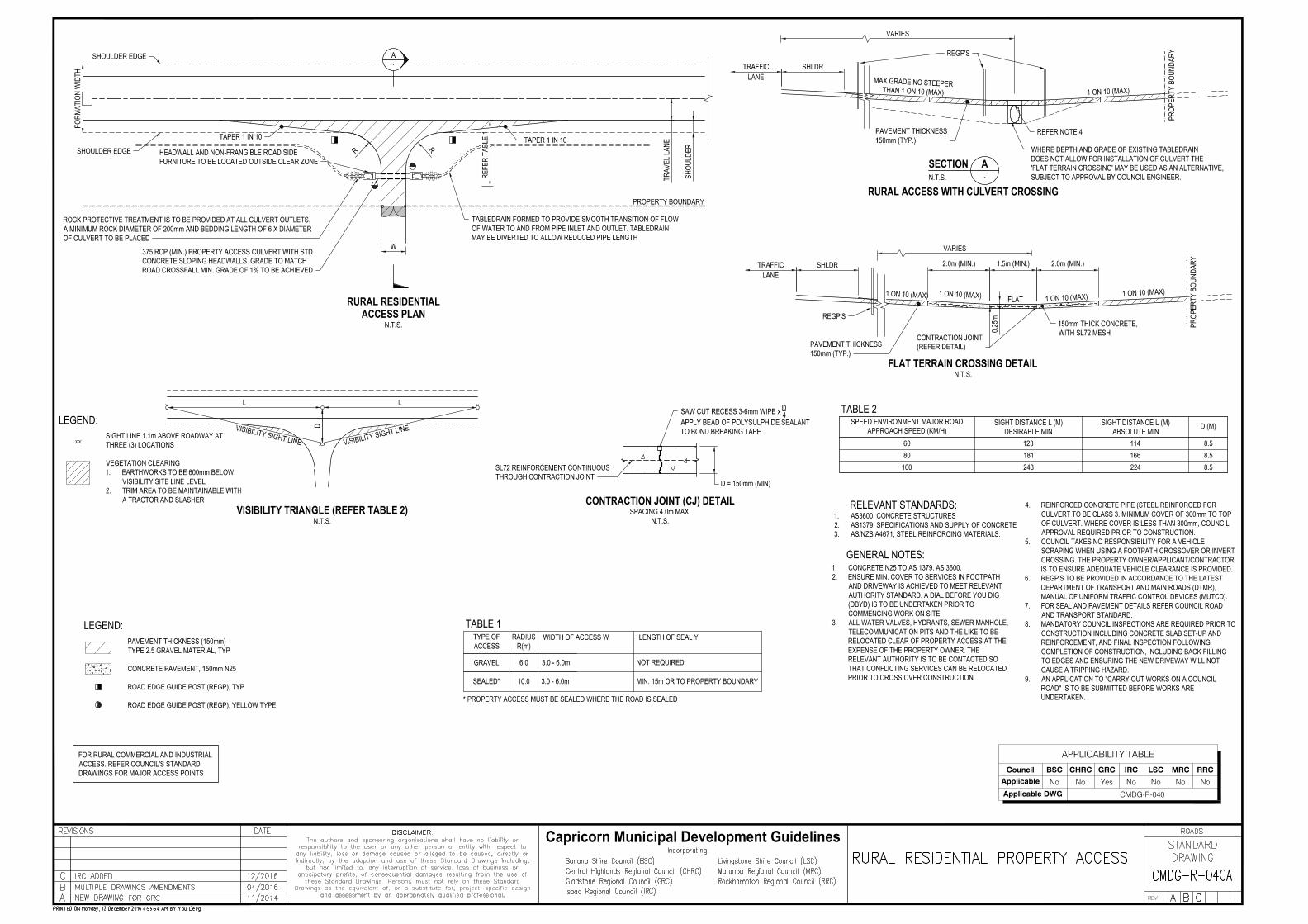
TABLE 2SPEED ENVIRONMENT MAJOR ROAD
APPROACH SPEED (KM/H)SIGHT DISTANCE L (M)
DESIRABLE MINSIGHT DISTANCE L (M)
ABSOLUTE MIN D (M)
60 123 114 8.580 181 166 8.5
100 248 224 8.5
VARIES
VARIES
GENERAL NOTES:
RELEVANT STANDARDS:1. AS3600, CONCRETE STRUCTURES2. AS1379, SPECIFICATIONS AND SUPPLY OF CONCRETE3. AS/NZS A4671, STEEL REINFORCING MATERIALS.
REGP'S
PAVEMENT THICKNESS150mm (TYP.)
1. CONCRETE N25 TO AS 1379, AS 3600.2. ENSURE MIN. COVER TO SERVICES IN FOOTPATH
AND DRIVEWAY IS ACHIEVED TO MEET RELEVANTAUTHORITY STANDARD. A DIAL BEFORE YOU DIG(DBYD) IS TO BE UNDERTAKEN PRIOR TOCOMMENCING WORK ON SITE.
3. ALL WATER VALVES, HYDRANTS, SEWER MANHOLE,TELECOMMUNICATION PITS AND THE LIKE TO BERELOCATED CLEAR OF PROPERTY ACCESS AT THEEXPENSE OF THE PROPERTY OWNER. THERELEVANT AUTHORITY IS TO BE CONTACTED SOTHAT CONFLICTING SERVICES CAN BE RELOCATEDPRIOR TO CROSS OVER CONSTRUCTION
4. REINFORCED CONCRETE PIPE (STEEL REINFORCED FORCULVERT TO BE CLASS 3. MINIMUM COVER OF 300mm TO TOPOF CULVERT. WHERE COVER IS LESS THAN 300mm, COUNCILAPPROVAL REQUIRED PRIOR TO CONSTRUCTION.
5. COUNCIL TAKES NO RESPONSIBILITY FOR A VEHICLESCRAPING WHEN USING A FOOTPATH CROSSOVER OR INVERTCROSSING. THE PROPERTY OWNER/APPLICANT/CONTRACTORIS TO ENSURE ADEQUATE VEHICLE CLEARANCE IS PROVIDED.
6. REGP'S TO BE PROVIDED IN ACCORDANCE TO THE LATESTDEPARTMENT OF TRANSPORT AND MAIN ROADS (DTMR),MANUAL OF UNIFORM TRAFFIC CONTROL DEVICES (MUTCD).
7. FOR SEAL AND PAVEMENT DETAILS REFER COUNCIL ROADAND TRANSPORT STANDARD.
8. MANDATORY COUNCIL INSPECTIONS ARE REQUIRED PRIOR TOCONSTRUCTION INCLUDING CONCRETE SLAB SET-UP ANDREINFORCEMENT, AND FINAL INSPECTION FOLLOWINGCOMPLETION OF CONSTRUCTION, INCLUDING BACK FILLINGTO EDGES AND ENSURING THE NEW DRIVEWAY WILL NOTCAUSE A TRIPPING HAZARD.
9. AN APPLICATION TO "CARRY OUT WORKS ON A COUNCILROAD" IS TO BE SUBMITTED BEFORE WORKS AREUNDERTAKEN.
FOR RURAL COMMERCIAL AND INDUSTRIALACCESS. REFER COUNCIL'S STANDARDDRAWINGS FOR MAJOR ACCESS POINTS
APPLICABILITY TABLE
Council BSC CHRC GRC IRC LSC MRC RRC
Applicable No No Yes No No No No
Applicable DWG CMDG-R-040
Capricorn Municipal Development Guidelines
APPLICABILITY TABLE
Council BSC CHRC GRC IRC LSC MRC RRC
Applicable Yes Yes No Yes Yes Yes Yes
Fabric SL62 SL62 SL72 SL62 SL62 SL62
Applicable DWG CMDG-R-041A
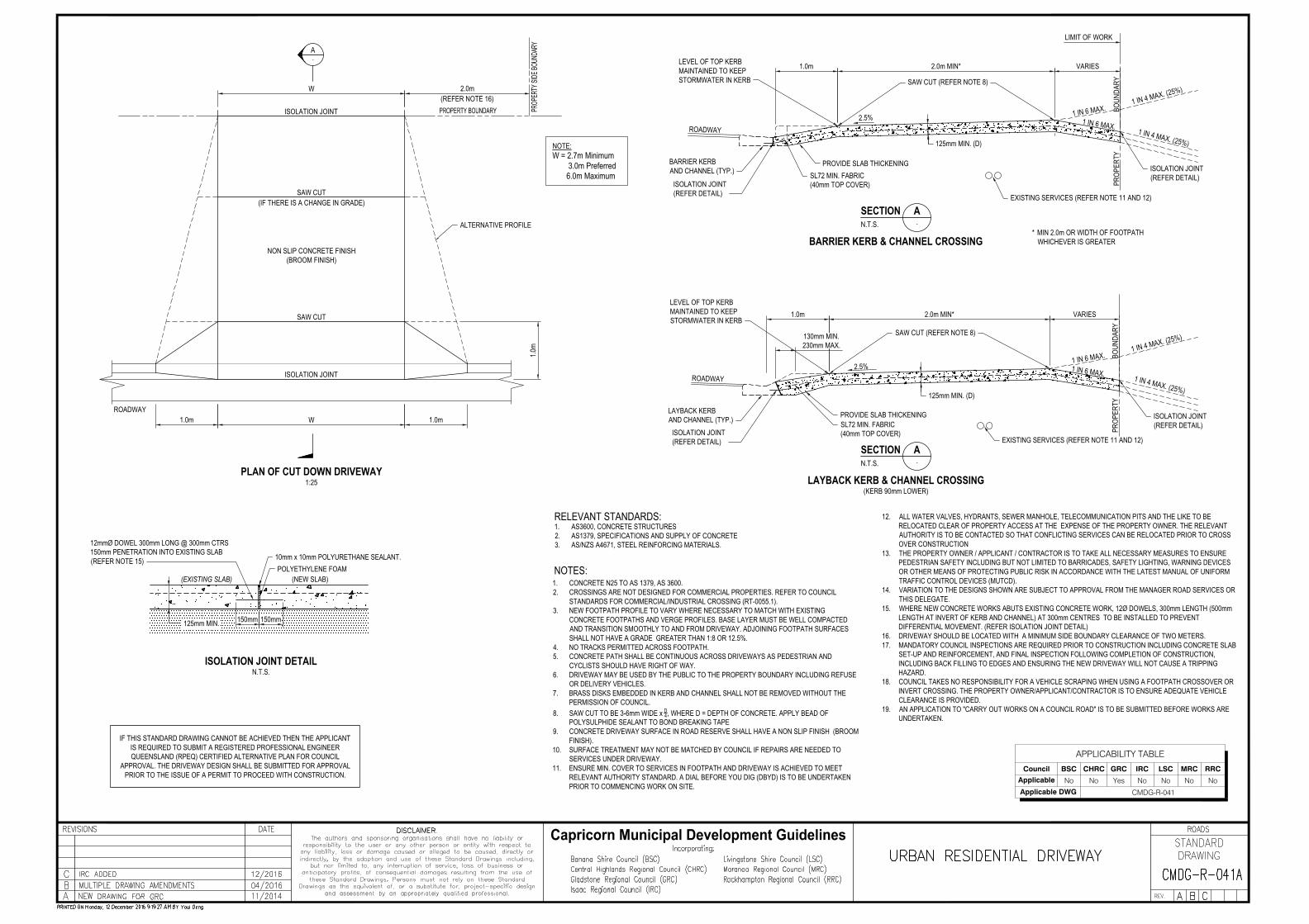
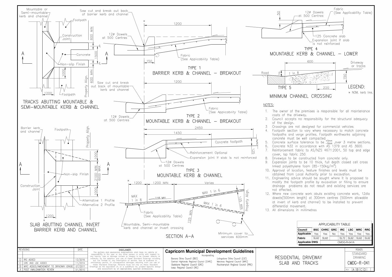
NOTE:W = 2.7m Minimum 3.0m Preferred 6.0m Maximum
W 2.0m(REFER NOTE 16)
1.0m
1.0m
ROADWAY
ISOLATION JOINT
NON SLIP CONCRETE FINISH(BROOM FINISH)
PLAN OF CUT DOWN DRIVEWAY1:25
ALTERNATIVE PROFILE
W1.0m
SAW CUT
ISOLATION JOINT
SAW CUT
(IF THERE IS A CHANGE IN GRADE)
1.0m 2.0m MIN*
PROVIDE SLAB THICKENING
1 IN 6 MAX.1 IN 6 MAX. 1 IN 4 MAX. (25%)
ROADWAY2.5%
1 IN 6 MAX. 1 IN 4 MAX. (25%)ROADWAY
2.5%1 IN 6 MAX.
1.0m 2.0m MIN*
PROVIDE SLAB THICKENING
130mm MIN.230mm MAX.
SL72 MIN. FABRIC(40mm TOP COVER)
125mm MIN. (D)
PROP
ERTY
BOUN
DARY
PROP
ERTY
BOUN
DARY
SECTION A-N.T.S.
BARRIER KERB & CHANNEL CROSSING
SECTION A-N.T.S.
LAYBACK KERB & CHANNEL CROSSING(KERB 90mm LOWER)
LAYBACK KERBAND CHANNEL (TYP.)
BARRIER KERBAND CHANNEL (TYP.)
EXISTING SERVICES (REFER NOTE 11 AND 12)
EXISTING SERVICES (REFER NOTE 11 AND 12)
1 IN 4 MAX. (25%)
1 IN 4 MAX. (25%)
ISOLATION JOINT(REFER DETAIL)
ISOLATION JOINT(REFER DETAIL)
LEVEL OF TOP KERBMAINTAINED TO KEEPSTORMWATER IN KERB
* MIN 2.0m OR WIDTH OF FOOTPATHWHICHEVER IS GREATER
SL72 MIN. FABRIC(40mm TOP COVER)
SAW CUT (REFER NOTE 8)
LEVEL OF TOP KERBMAINTAINED TO KEEPSTORMWATER IN KERB
SAW CUT (REFER NOTE 8)
125mm MIN. (D)
VARIES
VARIES
LIMIT OF WORK
ISOLATION JOINT(REFER DETAIL)
ISOLATION JOINT(REFER DETAIL)
10mm x 10mm POLYURETHANE SEALANT.POLYETHYLENE FOAM
ISOLATION JOINT DETAILN.T.S.
12mmØ DOWEL 300mm LONG @ 300mm CTRS150mm PENETRATION INTO EXISTING SLAB(REFER NOTE 15)
(EXISTING SLAB) (NEW SLAB)
125mm MIN. 150mm 150mm
NOTES:1. CONCRETE N25 TO AS 1379, AS 3600.2. CROSSINGS ARE NOT DESIGNED FOR COMMERCIAL PROPERTIES. REFER TO COUNCIL
STANDARDS FOR COMMERCIAL/INDUSTRIAL CROSSING (RT-0055.1).3. NEW FOOTPATH PROFILE TO VARY WHERE NECESSARY TO MATCH WITH EXISTING
CONCRETE FOOTPATHS AND VERGE PROFILES. BASE LAYER MUST BE WELL COMPACTEDAND TRANSITION SMOOTHLY TO AND FROM DRIVEWAY. ADJOINING FOOTPATH SURFACESSHALL NOT HAVE A GRADE GREATER THAN 1:8 OR 12.5%.
4. NO TRACKS PERMITTED ACROSS FOOTPATH.5. CONCRETE PATH SHALL BE CONTINUOUS ACROSS DRIVEWAYS AS PEDESTRIAN AND
CYCLISTS SHOULD HAVE RIGHT OF WAY.6. DRIVEWAY MAY BE USED BY THE PUBLIC TO THE PROPERTY BOUNDARY INCLUDING REFUSE
OR DELIVERY VEHICLES.7. BRASS DISKS EMBEDDED IN KERB AND CHANNEL SHALL NOT BE REMOVED WITHOUT THE
PERMISSION OF COUNCIL.8. SAW CUT TO BE 3-6mm WIDE x D4, WHERE D = DEPTH OF CONCRETE. APPLY BEAD OF
POLYSULPHIDE SEALANT TO BOND BREAKING TAPE9. CONCRETE DRIVEWAY SURFACE IN ROAD RESERVE SHALL HAVE A NON SLIP FINISH (BROOM
FINISH).10. SURFACE TREATMENT MAY NOT BE MATCHED BY COUNCIL IF REPAIRS ARE NEEDED TO
SERVICES UNDER DRIVEWAY.11. ENSURE MIN. COVER TO SERVICES IN FOOTPATH AND DRIVEWAY IS ACHIEVED TO MEET
RELEVANT AUTHORITY STANDARD. A DIAL BEFORE YOU DIG (DBYD) IS TO BE UNDERTAKENPRIOR TO COMMENCING WORK ON SITE.
RELEVANT STANDARDS:1. AS3600, CONCRETE STRUCTURES2. AS1379, SPECIFICATIONS AND SUPPLY OF CONCRETE3. AS/NZS A4671, STEEL REINFORCING MATERIALS.
A
IF THIS STANDARD DRAWING CANNOT BE ACHIEVED THEN THE APPLICANTIS REQUIRED TO SUBMIT A REGISTERED PROFESSIONAL ENGINEERQUEENSLAND (RPEQ) CERTIFIED ALTERNATIVE PLAN FOR COUNCIL
APPROVAL. THE DRIVEWAY DESIGN SHALL BE SUBMITTED FOR APPROVALPRIOR TO THE ISSUE OF A PERMIT TO PROCEED WITH CONSTRUCTION.
12. ALL WATER VALVES, HYDRANTS, SEWER MANHOLE, TELECOMMUNICATION PITS AND THE LIKE TO BERELOCATED CLEAR OF PROPERTY ACCESS AT THE EXPENSE OF THE PROPERTY OWNER. THE RELEVANTAUTHORITY IS TO BE CONTACTED SO THAT CONFLICTING SERVICES CAN BE RELOCATED PRIOR TO CROSSOVER CONSTRUCTION
13. THE PROPERTY OWNER / APPLICANT / CONTRACTOR IS TO TAKE ALL NECESSARY MEASURES TO ENSUREPEDESTRIAN SAFETY INCLUDING BUT NOT LIMITED TO BARRICADES, SAFETY LIGHTING, WARNING DEVICESOR OTHER MEANS OF PROTECTING PUBLIC RISK IN ACCORDANCE WITH THE LATEST MANUAL OF UNIFORMTRAFFIC CONTROL DEVICES (MUTCD).
14. VARIATION TO THE DESIGNS SHOWN ARE SUBJECT TO APPROVAL FROM THE MANAGER ROAD SERVICES ORTHIS DELEGATE.
15. WHERE NEW CONCRETE WORKS ABUTS EXISTING CONCRETE WORK, 12Ø DOWELS, 300mm LENGTH (500mmLENGTH AT INVERT OF KERB AND CHANNEL) AT 300mm CENTRES TO BE INSTALLED TO PREVENTDIFFERENTIAL MOVEMENT. (REFER ISOLATION JOINT DETAIL)
16. DRIVEWAY SHOULD BE LOCATED WITH A MINIMUM SIDE BOUNDARY CLEARANCE OF TWO METERS.17. MANDATORY COUNCIL INSPECTIONS ARE REQUIRED PRIOR TO CONSTRUCTION INCLUDING CONCRETE SLAB
SET-UP AND REINFORCEMENT, AND FINAL INSPECTION FOLLOWING COMPLETION OF CONSTRUCTION,INCLUDING BACK FILLING TO EDGES AND ENSURING THE NEW DRIVEWAY WILL NOT CAUSE A TRIPPINGHAZARD.
18. COUNCIL TAKES NO RESPONSIBILITY FOR A VEHICLE SCRAPING WHEN USING A FOOTPATH CROSSOVER ORINVERT CROSSING. THE PROPERTY OWNER/APPLICANT/CONTRACTOR IS TO ENSURE ADEQUATE VEHICLECLEARANCE IS PROVIDED.
19. AN APPLICATION TO "CARRY OUT WORKS ON A COUNCIL ROAD" IS TO BE SUBMITTED BEFORE WORKS AREUNDERTAKEN.
APPLICABILITY TABLE
Council BSC CHRC GRC IRC LSC MRC RRC
Applicable No No Yes No No No No
Applicable DWG CMDG-R-041

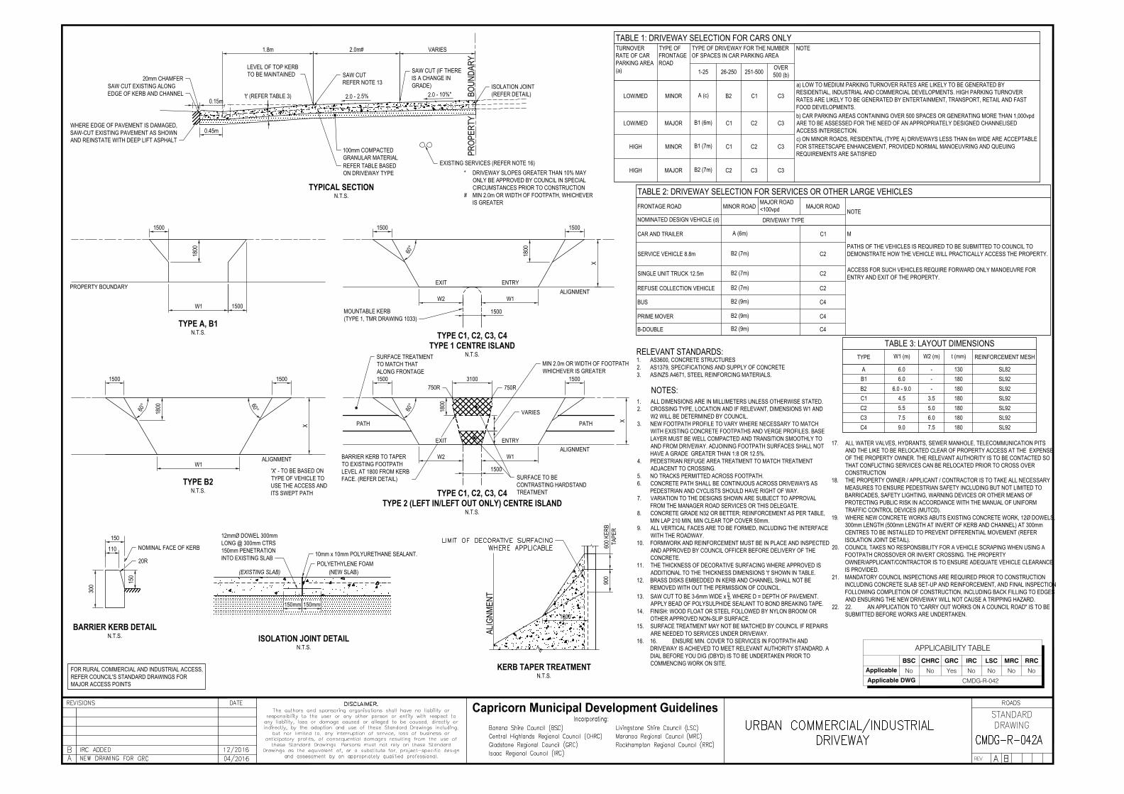
APPLICABILITY TABLE
BSC CHRC GRC IRC LSC MRC RRC
Applicable Yes Yes No Yes Yes Yes Yes
Applicable DWG CMDG-R-042A
W1 1500
1800
1500
15001500
60°
1800 60°
W1
PROPERTY BOUNDARY
TYPE A, B1N.T.S.
TYPE B2N.T.S.
180060°
1500
W2 W1
1500
1500
1500 1500
60°
W1W2
3100
1800
750R750R
MIN 2.0m OR WIDTH OF FOOTPATHWHICHEVER IS GREATER
1500
BARRIER KERB TO TAPERTO EXISTING FOOTPATHLEVEL AT 1800 FROM KERBFACE. (REFER DETAIL) SURFACE TO BE
CONTRASTING HARDSTANDTREATMENT
EXIT ENTRY
EXIT ENTRYALIGNMENT
PATH PATH
TYPE C1, C2, C3, C4TYPE 2 (LEFT IN/LEFT OUT ONLY) CENTRE ISLAND
N.T.S.
TYPE C1, C2, C3, C4TYPE 1 CENTRE ISLAND
N.T.S.SURFACE TREATMENTTO MATCH THATALONG FRONTAGE
VARIES
MOUNTABLE KERB(TYPE 1, TMR DRAWING 1033)
X
X
X
'X' - TO BE BASED ONTYPE OF VEHICLE TOUSE THE ACCESS ANDITS SWEPT PATH
ALIGNMENTALIGNMENT
600 K
ERB
TAPE
R90
0
1800
ALIG
NMEN
T
KERB TAPER TREATMENTN.T.S.
1.8m 2.0m# VARIES
0.45m
100mm COMPACTEDGRANULAR MATERIAL
ISOLATION JOINT(REFER DETAIL)2.0 - 2.5% 2.0 - 10%*
SAW CUT EXISTING ALONGEDGE OF KERB AND CHANNEL
WHERE EDGE OF PAVEMENT IS DAMAGED,SAW-CUT EXISTING PAVEMENT AS SHOWNAND REINSTATE WITH DEEP LIFT ASPHALT
0.15m
TYPICAL SECTIONN.T.S.
* DRIVEWAY SLOPES GREATER THAN 10% MAYONLY BE APPROVED BY COUNCIL IN SPECIALCIRCUMSTANCES PRIOR TO CONSTRUCTION
# MIN 2.0m OR WIDTH OF FOOTPATH, WHICHEVERIS GREATER
BOUN
DARY
PROP
ERTY
REFER TABLE BASEDON DRIVEWAY TYPE
20mm CHAMFER
EXISTING SERVICES (REFER NOTE 16)
't' (REFER TABLE 3)
LEVEL OF TOP KERBTO BE MAINTAINED SAW CUT
REFER NOTE 13
SAW CUT (IF THEREIS A CHANGE INGRADE)
10mm x 10mm POLYURETHANE SEALANT.POLYETHYLENE FOAM
ISOLATION JOINT DETAILN.T.S.
12mmØ DOWEL 300mmLONG @ 300mm CTRS150mm PENETRATIONINTO EXISTING SLAB
(EXISTING SLAB) (NEW SLAB)
150mm 150mm
BARRIER KERB DETAILN.T.S.
300
110
150
NOMINAL FACE OF KERB
20R
150
TABLE 3: LAYOUT DIMENSIONSTYPE W1 (m) W2 (m) t (mm) REINFORCEMENT MESH
A 6.0 - 130 SL82B1 6.0 - 180 SL92B2 6.0 - 9.0 - 180 SL92C1 4.5 3.5 180 SL92C2 5.5 5.0 180 SL92C3 7.5 6.0 180 SL92C4 9.0 7.5 180 SL92
NOTES:
TABLE 1: DRIVEWAY SELECTION FOR CARS ONLYTURNOVERRATE OF CARPARKING AREA(a)
TYPE OFFRONTAGEROAD
TYPE OF DRIVEWAY FOR THE NUMBEROF SPACES IN CAR PARKING AREA
NOTE
1-25 26-250 251-500OVER500 (b)
LOW/MED MINOR A (c) B2 C1 C3
a) LOW TO MEDIUM PARKING TURNOVER RATES ARE LIKELY TO BE GENERATED BYRESIDENTIAL, INDUSTRIAL AND COMMERCIAL DEVELOPMENTS. HIGH PARKING TURNOVERRATES ARE LIKELY TO BE GENERATED BY ENTERTAINMENT, TRANSPORT, RETAIL AND FASTFOOD DEVELOPMENTS.
LOW/MED MAJOR B1 (6m) C1 C2 C3b) CAR PARKING AREAS CONTAINING OVER 500 SPACES OR GENERATING MORE THAN 1,000vpdARE TO BE ASSESSED FOR THE NEED OF AN APPROPRIATELY DESIGNED CHANNELISEDACCESS INTERSECTION.
HIGH MINOR B1 (7m) C1 C2 C3c) ON MINOR ROADS, RESIDENTIAL (TYPE A) DRIVEWAYS LESS THAN 6m WIDE ARE ACCEPTABLEFOR STREETSCAPE ENHANCEMENT, PROVIDED NORMAL MANOEUVRING AND QUEUINGREQUIREMENTS ARE SATISFIED
HIGH MAJOR B2 (7m) C2 C3 C3
TABLE 2: DRIVEWAY SELECTION FOR SERVICES OR OTHER LARGE VEHICLESFRONTAGE ROAD MINOR ROAD
MAJOR ROAD<100vpd MAJOR ROAD
NOTENOMINATED DESIGN VEHICLE (d) DRIVEWAY TYPE
CAR AND TRAILER A (6m) C1 M
SERVICE VEHICLE 8.8m B2 (7m) C2PATHS OF THE VEHICLES IS REQUIRED TO BE SUBMITTED TO COUNCIL TODEMONSTRATE HOW THE VEHICLE WILL PRACTICALLY ACCESS THE PROPERTY.
SINGLE UNIT TRUCK 12.5m B2 (7m) C2 ACCESS FOR SUCH VEHICLES REQUIRE FORWARD ONLY MANOEUVRE FORENTRY AND EXIT OF THE PROPERTY.
REFUSE COLLECTION VEHICLE B2 (7m) C2
BUS B2 (9m) C4
PRIME MOVER B2 (9m) C4
B-DOUBLE B2 (9m) C4
RELEVANT STANDARDS:1. AS3600, CONCRETE STRUCTURES2. AS1379, SPECIFICATIONS AND SUPPLY OF CONCRETE3. AS/NZS A4671, STEEL REINFORCING MATERIALS.
FOR RURAL COMMERCIAL AND INDUSTRIAL ACCESS,REFER COUNCIL'S STANDARD DRAWINGS FORMAJOR ACCESS POINTS
1. ALL DIMENSIONS ARE IN MILLIMETERS UNLESS OTHERWISE STATED.2. CROSSING TYPE, LOCATION AND IF RELEVANT, DIMENSIONS W1 AND
W2 WILL BE DETERMINED BY COUNCIL.3. NEW FOOTPATH PROFILE TO VARY WHERE NECESSARY TO MATCH
WITH EXISTING CONCRETE FOOTPATHS AND VERGE PROFILES. BASELAYER MUST BE WELL COMPACTED AND TRANSITION SMOOTHLY TOAND FROM DRIVEWAY. ADJOINING FOOTPATH SURFACES SHALL NOTHAVE A GRADE GREATER THAN 1:8 OR 12.5%.
4. PEDESTRIAN REFUGE AREA TREATMENT TO MATCH TREATMENTADJACENT TO CROSSING.
5. NO TRACKS PERMITTED ACROSS FOOTPATH.6. CONCRETE PATH SHALL BE CONTINUOUS ACROSS DRIVEWAYS AS
PEDESTRIAN AND CYCLISTS SHOULD HAVE RIGHT OF WAY.7. VARIATION TO THE DESIGNS SHOWN ARE SUBJECT TO APPROVAL
FROM THE MANAGER ROAD SERVICES OR THIS DELEGATE.8. CONCRETE GRADE N32 OR BETTER; REINFORCEMENT AS PER TABLE,
MIN LAP 210 MIN, MIN CLEAR TOP COVER 50mm.9. ALL VERTICAL FACES ARE TO BE FORMED, INCLUDING THE INTERFACE
WITH THE ROADWAY.10. FORMWORK AND REINFORCEMENT MUST BE IN PLACE AND INSPECTED
AND APPROVED BY COUNCIL OFFICER BEFORE DELIVERY OF THECONCRETE.
11. THE THICKNESS OF DECORATIVE SURFACING WHERE APPROVED ISADDITIONAL TO THE THICKNESS DIMENSIONS 't' SHOWN IN TABLE.
12. BRASS DISKS EMBEDDED IN KERB AND CHANNEL SHALL NOT BEREMOVED WITH OUT THE PERMISSION OF COUNCIL.
13. SAW CUT TO BE 3-6mm WIDE x D4, WHERE D = DEPTH OF PAVEMENT.APPLY BEAD OF POLYSULPHIDE SEALANT TO BOND BREAKING TAPE.
14. FINISH: WOOD FLOAT OR STEEL FOLLOWED BY NYLON BROOM OROTHER APPROVED NON-SLIP SURFACE.
15. SURFACE TREATMENT MAY NOT BE MATCHED BY COUNCIL IF REPAIRSARE NEEDED TO SERVICES UNDER DRIVEWAY.
16. 16. ENSURE MIN. COVER TO SERVICES IN FOOTPATH ANDDRIVEWAY IS ACHIEVED TO MEET RELEVANT AUTHORITY STANDARD. ADIAL BEFORE YOU DIG (DBYD) IS TO BE UNDERTAKEN PRIOR TOCOMMENCING WORK ON SITE.
17. ALL WATER VALVES, HYDRANTS, SEWER MANHOLE, TELECOMMUNICATION PITSAND THE LIKE TO BE RELOCATED CLEAR OF PROPERTY ACCESS AT THE EXPENSEOF THE PROPERTY OWNER. THE RELEVANT AUTHORITY IS TO BE CONTACTED SOTHAT CONFLICTING SERVICES CAN BE RELOCATED PRIOR TO CROSS OVERCONSTRUCTION
18. THE PROPERTY OWNER / APPLICANT / CONTRACTOR IS TO TAKE ALL NECESSARYMEASURES TO ENSURE PEDESTRIAN SAFETY INCLUDING BUT NOT LIMITED TOBARRICADES, SAFETY LIGHTING, WARNING DEVICES OR OTHER MEANS OFPROTECTING PUBLIC RISK IN ACCORDANCE WITH THE MANUAL OF UNIFORMTRAFFIC CONTROL DEVICES (MUTCD).
19. WHERE NEW CONCRETE WORKS ABUTS EXISTING CONCRETE WORK, 12Ø DOWELS,300mm LENGTH (500mm LENGTH AT INVERT OF KERB AND CHANNEL) AT 300mmCENTRES TO BE INSTALLED TO PREVENT DIFFERENTIAL MOVEMENT (REFERISOLATION JOINT DETAIL).
20. COUNCIL TAKES NO RESPONSIBILITY FOR A VEHICLE SCRAPING WHEN USING AFOOTPATH CROSSOVER OR INVERT CROSSING. THE PROPERTYOWNER/APPLICANT/CONTRACTOR IS TO ENSURE ADEQUATE VEHICLE CLEARANCEIS PROVIDED.
21. MANDATORY COUNCIL INSPECTIONS ARE REQUIRED PRIOR TO CONSTRUCTIONINCLUDING CONCRETE SLAB SET-UP AND REINFORCEMENT, AND FINAL INSPECTIONFOLLOWING COMPLETION OF CONSTRUCTION, INCLUDING BACK FILLING TO EDGESAND ENSURING THE NEW DRIVEWAY WILL NOT CAUSE A TRIPPING HAZARD.
22. 22. AN APPLICATION TO "CARRY OUT WORKS ON A COUNCIL ROAD" IS TO BESUBMITTED BEFORE WORKS ARE UNDERTAKEN.
APPLICABILITY TABLE
BSC CHRC GRC IRC LSC MRC RRC
Applicable No No Yes No No No No
Applicable DWG CMDG-R-042
APPLICABILITY TABLE
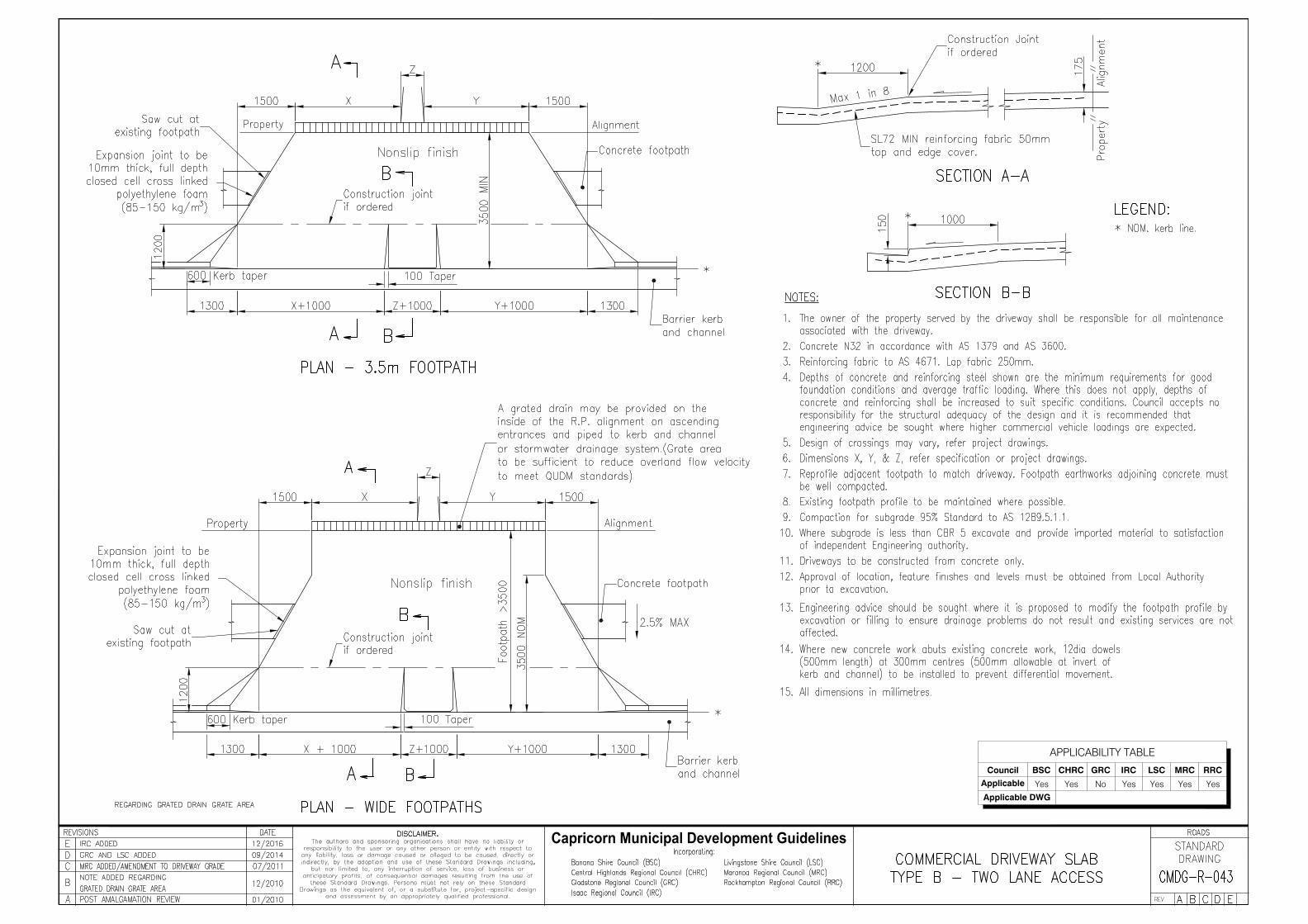
Council BSC CHRC GRC IRC LSC MRC RRC
Applicable Yes Yes No Yes Yes Yes Yes
Applicable DWG
APPLICABILITY TABLE
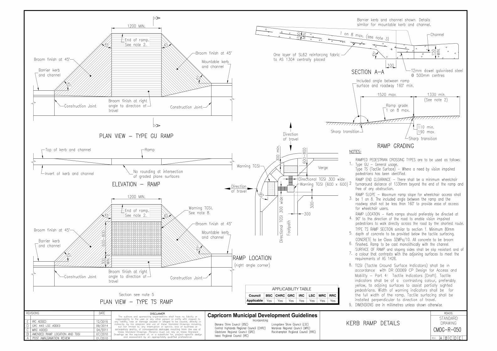
Council BSC CHRC GRC IRC LSC MRC RRC
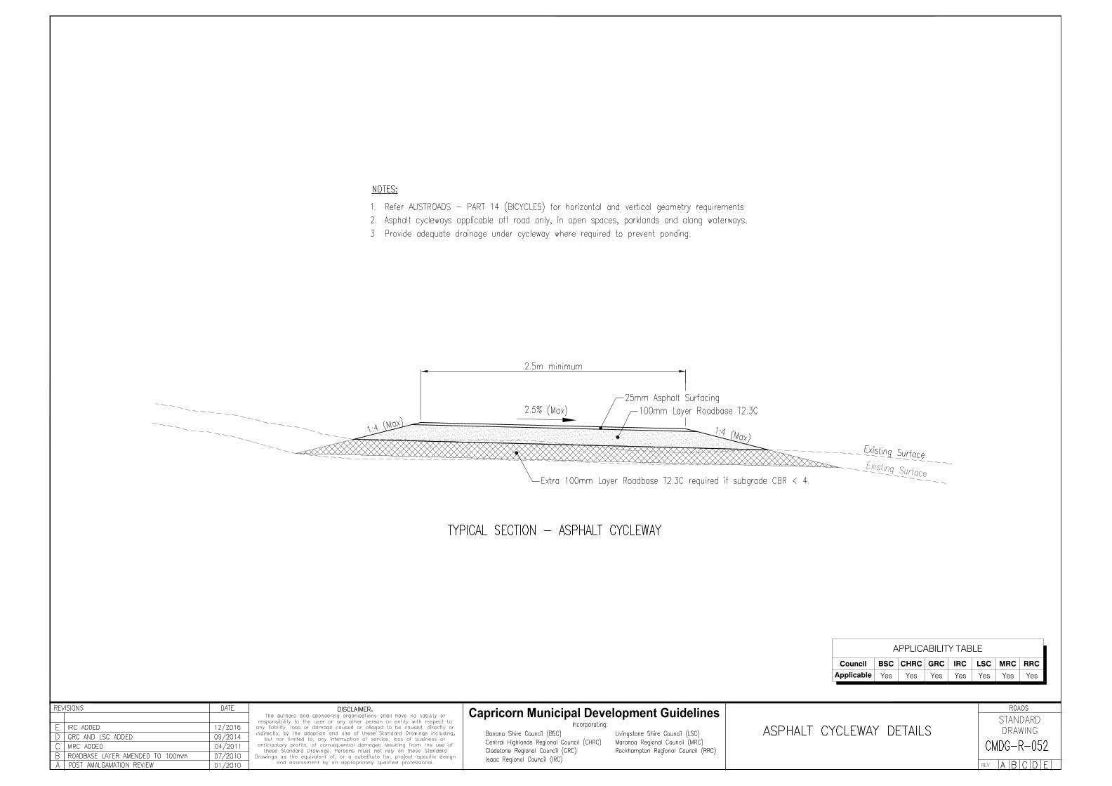
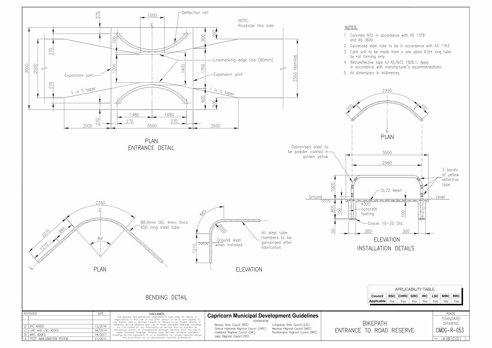
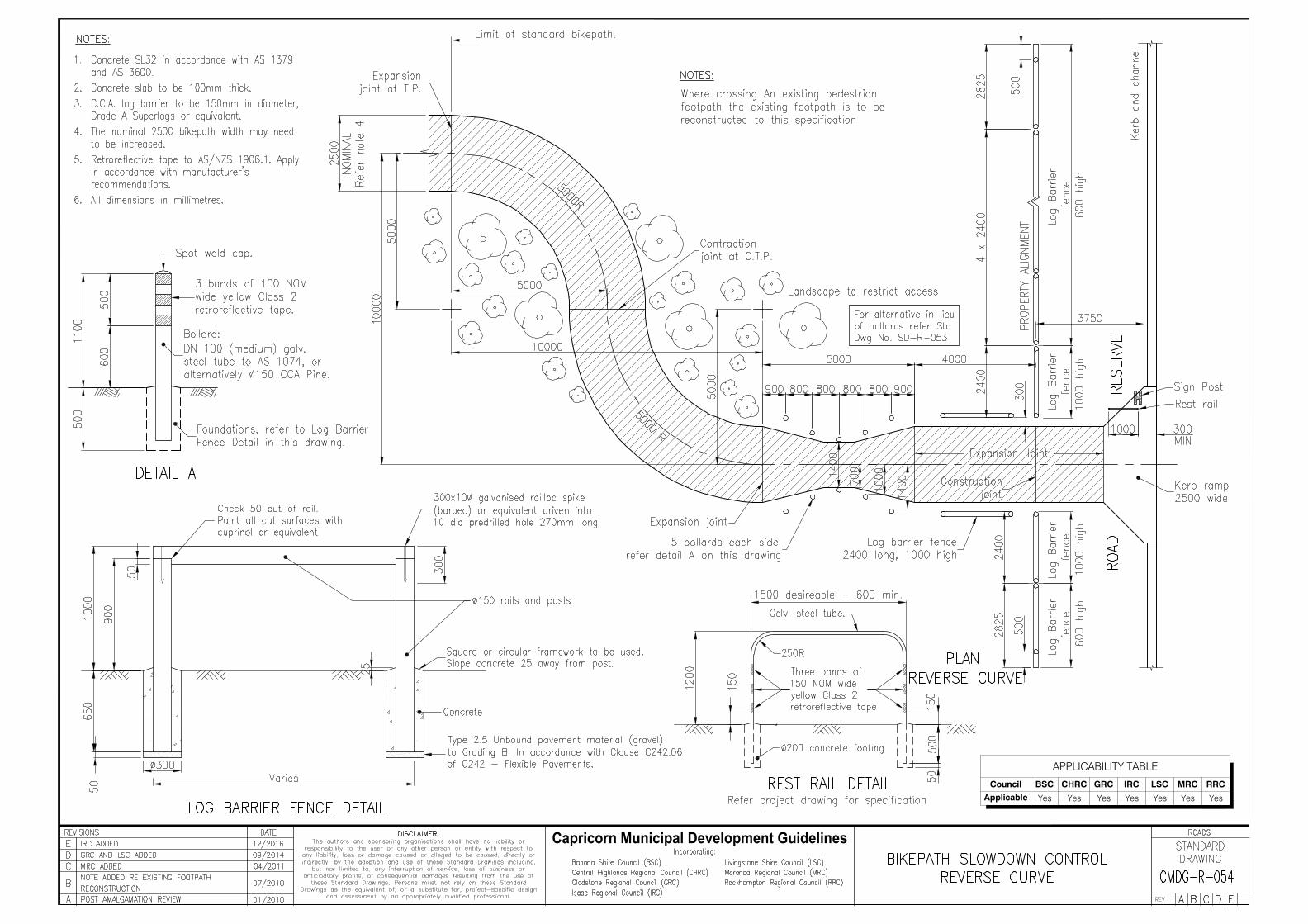
Applicable Yes Yes Yes Yes Yes Yes Yes
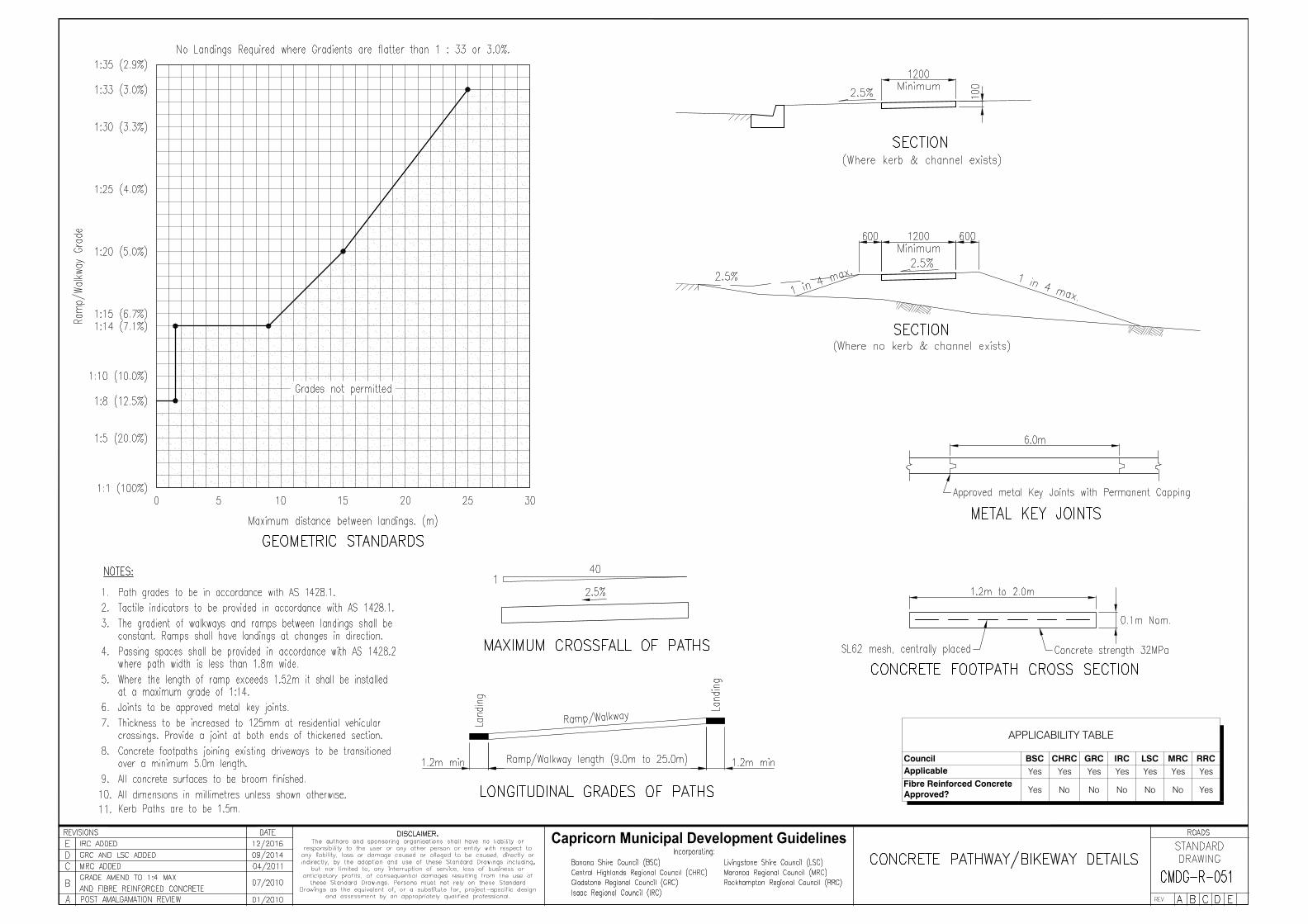
APPLICABILITY TABLE
Council BSC CHRC GRC IRC LSC MRC RRCApplicable Yes Yes Yes Yes Yes Yes YesFibre Reinforced ConcreteApproved? Yes No No No No No Yes
APPLICABILITY TABLE
Council BSC CHRC GRC IRC LSC MRC RRC
Applicable Yes Yes Yes Yes Yes Yes Yes
APPLICABILITY TABLE
Council BSC CHRC GRC IRC LSC MRC RRC
Applicable Yes Yes Yes Yes Yes Yes Yes
APPLICABILITY TABLE
Council BSC CHRC GRC IRC LSC MRC RRC
Applicable Yes Yes Yes Yes Yes Yes Yes
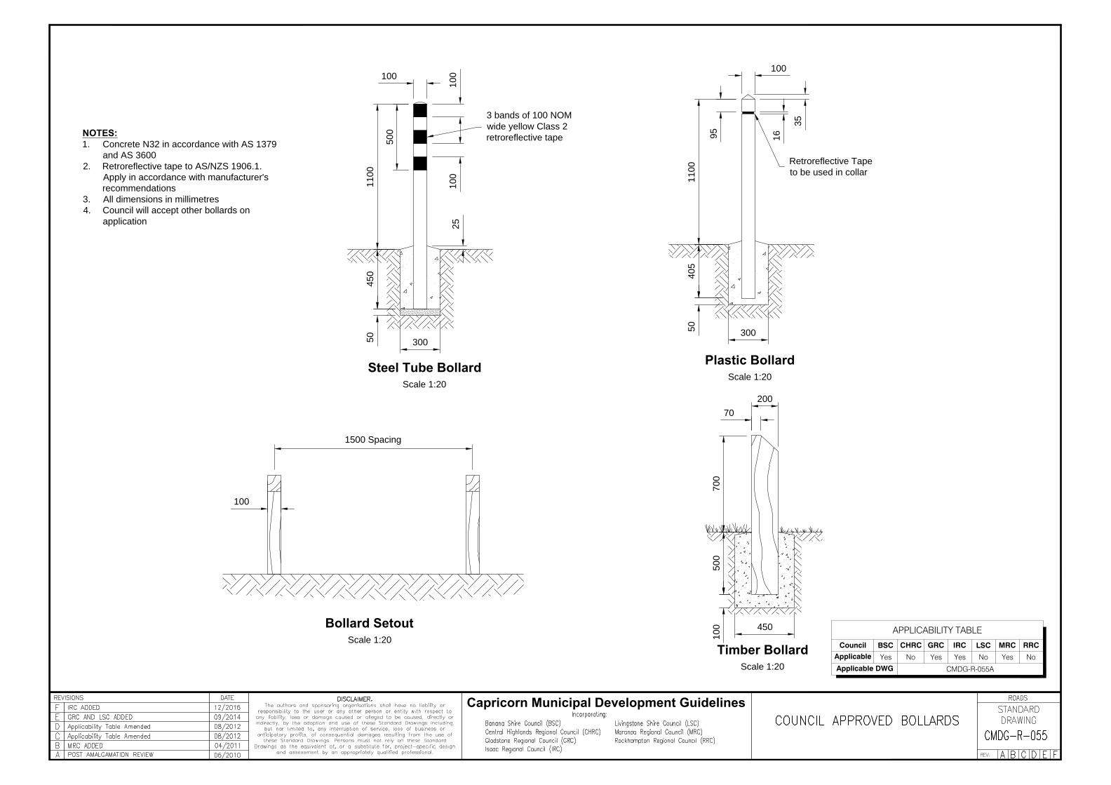
100
100
100
500
1100
450
50
25
70
200
700
500
100
450
100
35
95
16
1100
405
50
100
1500 Spacing
Timber Bollard
Scale 1:20
Steel Tube Bollard
Scale 1:20
300
Plastic Bollard
Scale 1:20
300
Retroreflective Tape
to be used in collar
3 bands of 100 NOM
wide yellow Class 2
retroreflective tape
Bollard Setout
Scale 1:20
NOTES:
1. Concrete N32 in accordance with AS 1379
and AS 3600
2. Retroreflective tape to AS/NZS 1906.1.
Apply in accordance with manufacturer's
recommendations
3. All dimensions in millimetres
4. Council will accept other bollards on
application
Capricorn Municipal Development Guidelines
APPLICABILITY TABLE
Council BSC CHRC GRC IRC LSC MRC RRC
Applicable Yes No Yes Yes No Yes No
Applicable DWG CMDG-R-055A
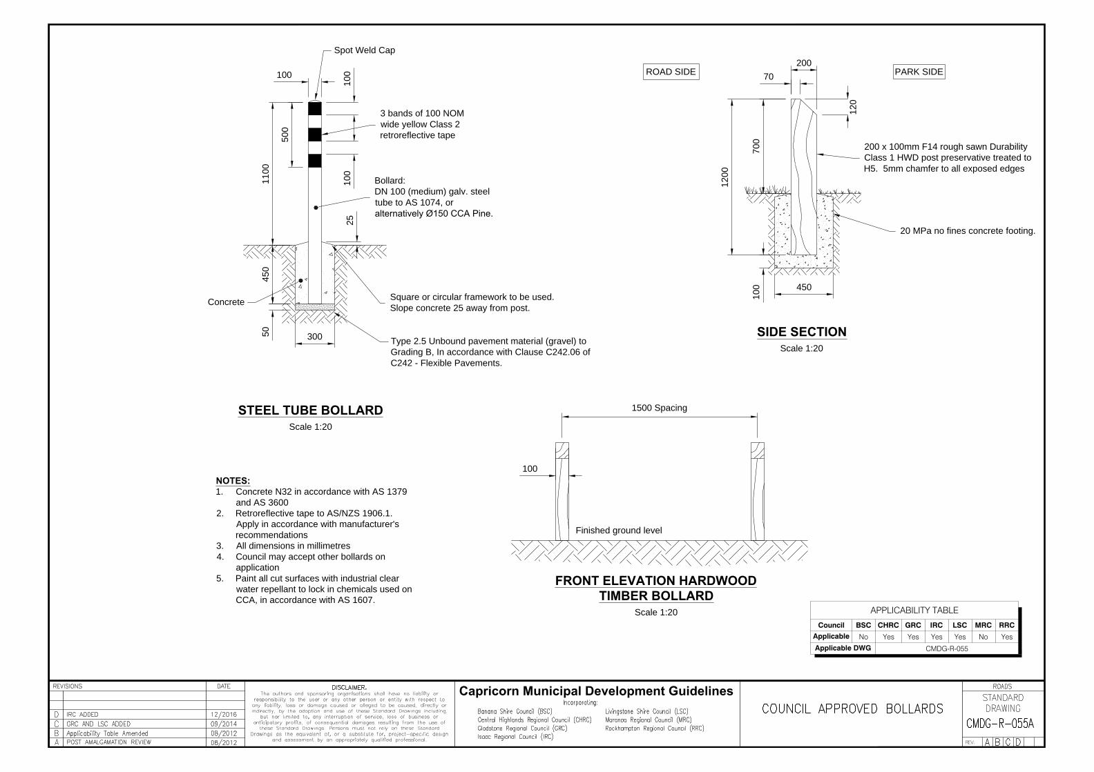
100
100
100
500
1100
450
50
25
70
200
700
100
450
100
1500 Spacing
SIDE SECTION
Scale 1:20
STEEL TUBE BOLLARD
Scale 1:20
300
3 bands of 100 NOM
wide yellow Class 2
retroreflective tape
FRONT ELEVATION HARDWOOD
TIMBER BOLLARD
Scale 1:20
NOTES:
1. Concrete N32 in accordance with AS 1379
and AS 3600
2. Retroreflective tape to AS/NZS 1906.1.
Apply in accordance with manufacturer's
recommendations
3. All dimensions in millimetres
4. Council may accept other bollards on
application
5. Paint all cut surfaces with industrial clear
water repellant to lock in chemicals used on
CCA, in accordance with AS 1607.
Capricorn Municipal Development Guidelines
Bollard:
DN 100 (medium) galv. steel
tube to AS 1074, or
alternatively Ø150 CCA Pine.
Concrete
Finished ground level
Square or circular framework to be used.
Slope concrete 25 away from post.
Type 2.5 Unbound pavement material (gravel) to
Grading B, In accordance with Clause C242.06 of
C242 - Flexible Pavements.
200 x 100mm F14 rough sawn Durability
Class 1 HWD post preservative treated to
H5. 5mm chamfer to all exposed edges
20 MPa no fines concrete footing.
120
1200
PARK SIDEROAD SIDE
Spot Weld Cap
APPLICABILITY TABLE
Council BSC CHRC GRC IRC LSC MRC RRC
Applicable No Yes Yes Yes Yes No Yes
Applicable DWG CMDG-R-055
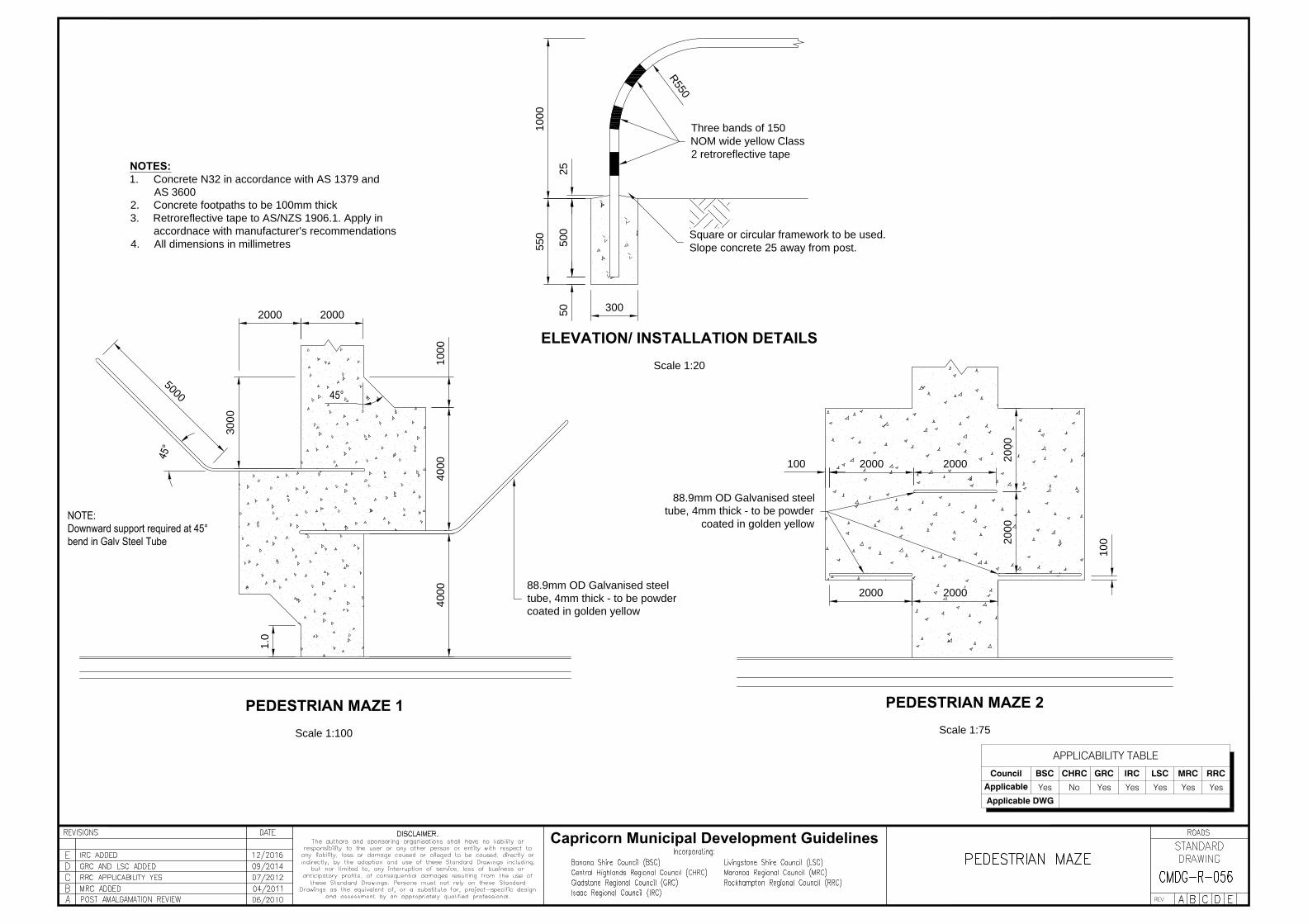
20002000
1000
3000
4000
4000
300
1000
550
25
500
50
Three bands of 150
NOM wide yellow Class
2 retroreflective tape
R
5
5
0
88.9mm OD Galvanised steel
tube, 4mm thick - to be powder
coated in golden yellow
1.0
5
0
0
0
2000
2000
2000
2000
2000
2000
88.9mm OD Galvanised steel
tube, 4mm thick - to be powder
coated in golden yellow
100
100
Square or circular framework to be used.
Slope concrete 25 away from post.
NOTES:
1. Concrete N32 in accordance with AS 1379 and
AS 3600
2. Concrete footpaths to be 100mm thick
3. Retroreflective tape to AS/NZS 1906.1. Apply in
accordnace with manufacturer's recommendations
4. All dimensions in millimetres
PEDESTRIAN MAZE 1
Scale 1:100
ELEVATION/ INSTALLATION DETAILS
Scale 1:20
PEDESTRIAN MAZE 2
Scale 1:75
Capricorn Municipal Development Guidelines
APPLICABILITY TABLE
Council BSC CHRC GRC IRC LSC MRC RRC
Applicable Yes No Yes Yes Yes Yes Yes
Applicable DWG

SISD
SISD
*
5m (3m min)
Conflict Point - dependent upon
vehicle paths and carriageway widths
NO LANDSCAPING ZONE
SISD =
D x V
3.6
+
V²
254 x (d+0.01xa)
T
SISD - Safe Intersection Sight Distance
D - decision time (s)T
V - operating (85th percentile) speed (km/h)
d - coefficient of deceleration
a - longitudinal grade in %
NOTES:
1. Model based on Department of Transport and Main Roads - Road
Planning and Design Manual
2. All values used in equation for SISD can be found in the manual
3. No Landscaping Zone means no standing shrubs or trees - ground
landscaping (ie) low laying gardens are subject to approval.
4. Sight distance models must be approved by Council
5. All landscaping are to be in accordance with approved species list
6. For distances regarding landscaping around power poles and
street lights refer to CMDG-G-016 Street Planting
7. Subsurface drainage is required where landscaping is approved in
centre median
8. Any trees planted in centre median should be set back a minimum
of 600mm behind back of kerb
TP
Capricorn Municipal Development Guidelines
APPLICABILITY TABLE
Council BSC CHRC GRC IRC LSC MRC RRC
Applicable Yes No Yes Yes Yes Yes Yes
Applicable DWG

Capricorn Municipal Development Guidelines
APPLICABILITY TABLE
Council BSC CHRC GRC IRC LSC MRC RRC
Applicable No Yes Yes Yes Yes Yes Yes
Applicable DWG CMDG-R-60A (BSC)

APPLICABILITY TABLE
Council BSC CHRC GRC IRC LSC MRC RRC
Applicable Yes No Yes No No No No
Applicable DWG CMDG-R-060

APPLICABILITY TABLE
Council BSC CHRC GRC IRC LSC MRC RRC
Applicable Yes Yes Yes Yes Yes Yes Yes

APPLICABILITY TABLE
Council BSC CHRC GRC IRC LSC MRC RRC
Applicable Yes Yes Yes Yes Yes Yes Yes
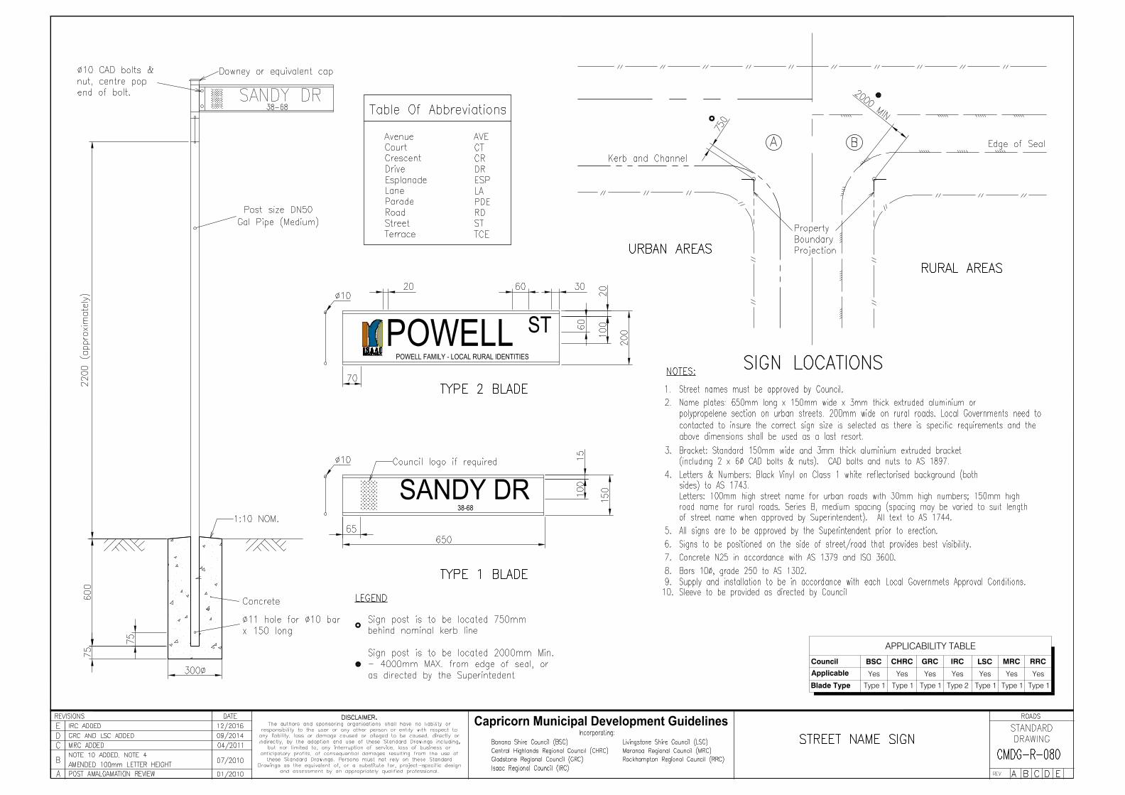
38-68
APPLICABILITY TABLE
Council BSC CHRC GRC IRC LSC MRC RRC
Applicable Yes Yes Yes Yes Yes Yes Yes
Blade Type Type 1 Type 1 Type 1 Type 2 Type 1 Type 1 Type 1
POWELL STPOWELL FAMILY - LOCAL RURAL IDENTITIES
APPLICABILITY TABLE
Council BSC CHRC GRC IRC LSC MRC RRC
Applicable Yes Yes Yes Yes Yes Yes Yes
W2-1
W2-1
W2-1
W2-1
R1-1
R1-1
W8-27
PREPARE
TO
STOP
W8-27
PREPARE
TO
STOP
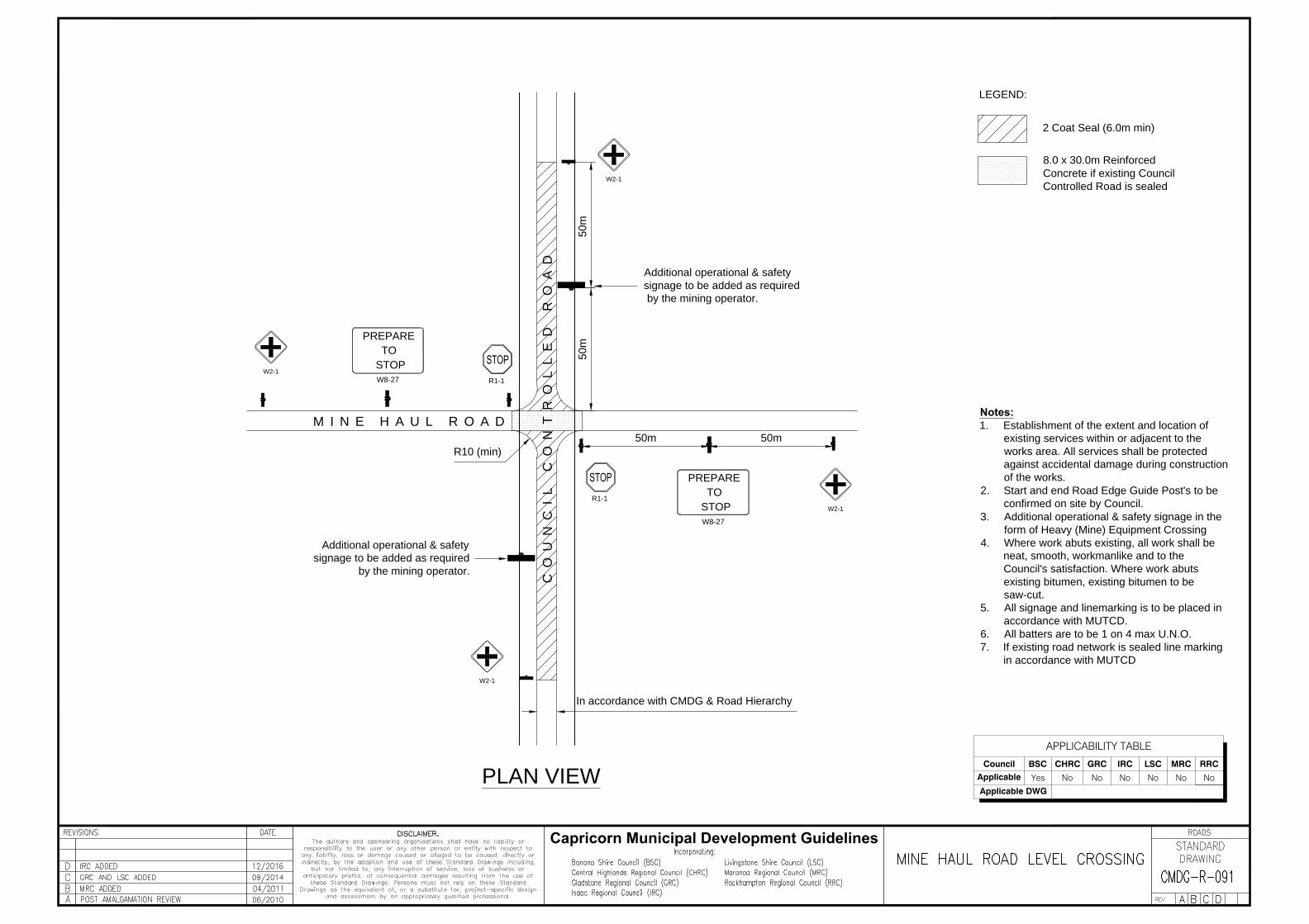
Notes:
1. Establishment of the extent and location of
existing services within or adjacent to the
works area. All services shall be protected
against accidental damage during construction
of the works.
2. Start and end Road Edge Guide Post's to be
confirmed on site by Council.
3. Additional operational & safety signage in the
form of Heavy (Mine) Equipment Crossing
4. Where work abuts existing, all work shall be
neat, smooth, workmanlike and to the
Council's satisfaction. Where work abuts
existing bitumen, existing bitumen to be
saw-cut.
5. All signage and linemarking is to be placed in
accordance with MUTCD.
6. All batters are to be 1 on 4 max U.N.O.
7. If existing road network is sealed line marking
in accordance with MUTCD
Additional operational & safety
signage to be added as required
by the mining operator.
Additional operational & safety
signage to be added as required
by the mining operator.
M I N E H A U L R O A D
CO
UN
CI
L
CO
NT
RO
LL
ED
R
OA
D
50m 50m
50m
50
m
2 Coat Seal (6.0m min)
8.0 x 30.0m Reinforced
Concrete if existing Council
Controlled Road is sealed
LEGEND:
PLAN VIEW
In accordance with CMDG & Road Hierarchy
R10 (min)
Capricorn Municipal Development Guidelines
APPLICABILITY TABLE
Council BSC CHRC GRC IRC LSC MRC RRC
Applicable Yes No No No No No No
Applicable DWG

PROPERTY BOUNDARY
P
R
O
P
E
R
T
Y
B
O
U
N
D
A
R
Y
CORRIDOR
LICENSE
UTILITY ASSET
PROPOSED
GAS MAIN
FENCE LINE
PIPELINE MARKER POST
CONCRETE
SLABS
CONCRETE SLABS
MARKER TAPE
MARKER TAPE
LAYOUT PLANOPEN CUT TRENCH
LAYOUT PLANBORED TRENCH
PIPELINE
MARKER
POST
PRECAST SLAB PLAN
PROPOSED
GAS MAIN
CONCRETE
SLABS
MARKER TAPE
TRENCH DETAIL (TYP)LIFTING
HOOK
RL1018 MESH.
CENTRALLY LOCATED
N.T.S.N.T.S.
N.T.S.
N.T.S.
COMPACTED
BEDDING
SAND
TREATMENT AND SIGNAGESEALED/UNSEALED ROADS
N.T.S.
NOTES
1. Road design standard in accordance with
CMDG & Council Road Heirarchy
2. Where road reserve width is > 30m
marker post to be place 15m left and right from
centre of road pavement
Yellow & Red
striped guide post
Yellow & Red
striped guide post
LNG Pipeline
Yellow & Red
striped guide post
Yellow & Red
striped guide post
Designed Pavement 30yrs (min)
Asphalt Surfacing
25mm Rural Access
35mm Minor Collector
50mm Major Collector
Existing road
surface
Existing road surface
Marker post
(see notes)
Property Boundary
Property Boundary
Marker post
(see notes)
Asphalt surfacing
DANGER - GAS MAIN
APPLICABILITY TABLE
Council BSC CHRC GRC IRC LSC MRC RRC
Applicable Yes Yes Yes Yes Yes Yes Yes
Applicable DWG
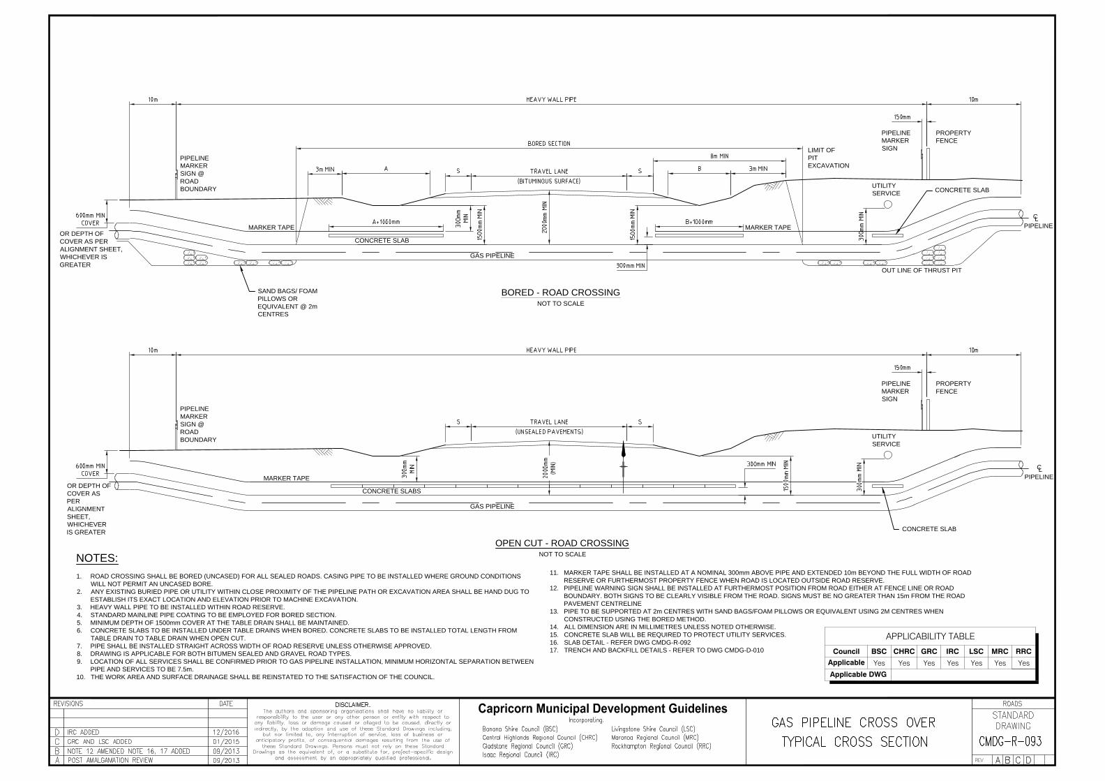
OPEN CUT - ROAD CROSSING
BORED - ROAD CROSSING
NOT TO SCALE
NOT TO SCALE
MARKER TAPE
UTILITY
SERVICE
PIPELINE
MARKER
SIGN
PROPERTY
FENCE
OUT LINE OF THRUST PIT
CONCRETE SLAB
GAS PIPELINE
LIMIT OF
PIT
EXCAVATION
CONCRETE SLABS
UTILITY
SERVICE
PIPELINE
MARKER
SIGN
PROPERTY
FENCE
MARKER TAPE
PIPELINE
MARKER
SIGN @
ROAD
BOUNDARY
GAS PIPELINE
PIPELINE
MARKER
SIGN @
ROAD
BOUNDARY
MARKER TAPE
SAND BAGS/ FOAM
PILLOWS OR
EQUIVALENT @ 2m
CENTRES
PIPELINE
PIPELINE
C
L
C
L
NOTES:
1. ROAD CROSSING SHALL BE BORED (UNCASED) FOR ALL SEALED ROADS. CASING PIPE TO BE INSTALLED WHERE GROUND CONDITIONS
WILL NOT PERMIT AN UNCASED BORE.
2. ANY EXISTING BURIED PIPE OR UTILITY WITHIN CLOSE PROXIMITY OF THE PIPELINE PATH OR EXCAVATION AREA SHALL BE HAND DUG TO
ESTABLISH ITS EXACT LOCATION AND ELEVATION PRIOR TO MACHINE EXCAVATION.
3. HEAVY WALL PIPE TO BE INSTALLED WITHIN ROAD RESERVE.
4. STANDARD MAINLINE PIPE COATING TO BE EMPLOYED FOR BORED SECTION.
5. MINIMUM DEPTH OF 1500mm COVER AT THE TABLE DRAIN SHALL BE MAINTAINED.
6. CONCRETE SLABS TO BE INSTALLED UNDER TABLE DRAINS WHEN BORED. CONCRETE SLABS TO BE INSTALLED TOTAL LENGTH FROM
TABLE DRAIN TO TABLE DRAIN WHEN OPEN CUT.
7. PIPE SHALL BE INSTALLED STRAIGHT ACROSS WIDTH OF ROAD RESERVE UNLESS OTHERWISE APPROVED.
8. DRAWING IS APPLICABLE FOR BOTH BITUMEN SEALED AND GRAVEL ROAD TYPES.
9. LOCATION OF ALL SERVICES SHALL BE CONFIRMED PRIOR TO GAS PIPELINE INSTALLATION, MINIMUM HORIZONTAL SEPARATION BETWEEN
PIPE AND SERVICES TO BE 7.5m.
10. THE WORK AREA AND SURFACE DRAINAGE SHALL BE REINSTATED TO THE SATISFACTION OF THE COUNCIL.
11. MARKER TAPE SHALL BE INSTALLED AT A NOMINAL 300mm ABOVE PIPE AND EXTENDED 10m BEYOND THE FULL WIDTH OF ROAD
RESERVE OR FURTHERMOST PROPERTY FENCE WHEN ROAD IS LOCATED OUTSIDE ROAD RESERVE.
12. PIPELINE WARNING SIGN SHALL BE INSTALLED AT FURTHERMOST POSITION FROM ROAD EITHER AT FENCE LINE OR ROAD
BOUNDARY. BOTH SIGNS TO BE CLEARLY VISIBLE FROM THE ROAD. SIGNS MUST BE NO GREATER THAN 15m FROM THE ROAD
PAVEMENT CENTRELINE
13. PIPE TO BE SUPPORTED AT 2m CENTRES WITH SAND BAGS/FOAM PILLOWS OR EQUIVALENT USING 2M CENTRES WHEN
CONSTRUCTED USING THE BORED METHOD.
14. ALL DIMENSION ARE IN MILLIMETRES UNLESS NOTED OTHERWISE.
15. CONCRETE SLAB WILL BE REQUIRED TO PROTECT UTILITY SERVICES.
16. SLAB DETAIL - REFER DWG CMDG-R-092
17. TRENCH AND BACKFILL DETAILS - REFER TO DWG CMDG-D-010
OR DEPTH OF
COVER AS PER
ALIGNMENT SHEET,
WHICHEVER IS
GREATER
OR DEPTH OF
COVER AS
PER
ALIGNMENT
SHEET,
WHICHEVER
IS GREATER
CONCRETE SLAB
CONCRETE SLAB
APPLICABILITY TABLE
Council BSC CHRC GRC IRC LSC MRC RRC
Applicable Yes Yes Yes Yes Yes Yes Yes
Applicable DWG
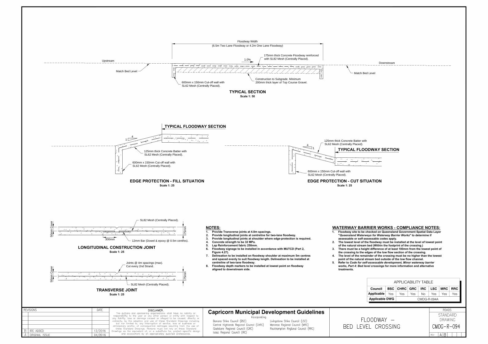
1. Provide Transverse joints at 4.0m spacings.
2. Provide longitudinal joints at centreline for two-lane floodway.
3. Provide longitudinal joints at shoulder where edge-protection is required.
4. Concrete strength to be 32 MPa.
5. Lap Reinforcement fabric 250mm.
6. Floodway signage to be installed in accordance with MUTCD (Part 2,
Figure 4.27).
7. Delineation to be installed on floodway shoulder at maximum 5m centres
and spaced evenly to suit floodway length. Delineation to be installed at
centreline of two-lane floodway.
8. Floodway depth markers to be installed at lowest point on floodway
aligned to downstream side.
LONGITUDINAL CONSTRUCTION JOINT
Scale 1: 25
WATERWAY BARRIER WORKS - COMPLIANCE NOTES:
1. Floodway site to be checked on Queensland Government Spatial Data Layer
"Queensland Waterways for Waterway Barrier Works" to determine if
assessable or self-assessable codes apply.
2. The lowest level of the floodway must be installed at the level of lowest point
of the natural stream bed (Within the footprint of the crossing.)
3. There must be a height difference of at least 100mm from the lowest point of
the crossing to the edges of the low flow section of the crossing.
4. The level of the remainder of the crossing must be no higher than the lowest
point of the natural stream bed outside of the low flow channel.
5. Refer to Code for self-assessable development, Minor waterway barrier
works, Part 4: Bed level crossings for more information and alternative
treatments.
SL82 Mesh (Centrally Placed).
12mm Bar (Dowel & epoxy @ 0.5m centres).
50m
m C
over
17
5m
m
300mm
TYPICAL SECTION
Scale 1: 50
1.0%
Upstream
Downstream
175mm thick Concrete Floodway reinforced
with SL82 Mesh (Centrally Placed).
600mm x 150mm Cut-off wall with
SL62 Mesh (Centrally Placed).
Match Bed Level
Match Bed Level
Construction to Subgrade. Minimum
200mm thick layer of Top Course Gravel.
Floodway Width
(6.5m Two Lane Floodway or 4.2m One Lane Floodway)
Joints @ 4m spacings (max).
Cut every 2nd Strand.
TRANSVERSE JOINT
Scale 1: 25
SL82 Mesh (Centrally Placed).
50
mm
C
over
17
5m
m
EDGE PROTECTION - CUT SITUATION
Scale 1: 25
EDGE PROTECTION - FILL SITUATION
Scale 1: 25
125mm thick Concrete Batter with
SL62 Mesh (Centrally Placed).
600mm x 150mm Cut-off wall with
SL62 Mesh (Centrally Placed).
TYPICAL FLOODWAY SECTION
TYPICAL FLOODWAY SECTION
600mm x 150mm Cut-off wall with
SL62 Mesh (Centrally Placed).
125mm thick Concrete Batter with
SL62 Mesh (Centrally Placed).
4
1
1
4
APPLICABILITY TABLE
Council BSC CHRC GRC IRC LSC MRC RRC
Applicable Yes Yes Yes No Yes Yes Yes
Applicable DWG CMDG-R-094A

1. Provide Transverse joints at 4.0m spacings.
2. Provide longitudinal joints at shoulder where edge-protection is required.
3. Concrete strength to be 32 MPa.
4. Lap Reinforcement fabric 250mm.
5. Floodway signage to be installed in accordance with MUTCD (Part 2,
Figure 4.27).
6. Delineation to be installed on floodway shoulder at maximum 5m centres
and spaced evenly to suit floodway length. Delineation to be installed at
centreline of two-lane floodway.
7. Floodway depth markers to be installed at lowest point on floodway
aligned to downstream side U.N.O.
LONGITUDINAL CONSTRUCTION JOINT
Scale 1: 25
WATERWAY BARRIER WORKS - COMPLIANCE NOTES:
1. Floodway site to be checked on Queensland Government Spatial Data Layer
"Queensland Waterways for Waterway Barrier Works" to determine if
assessable or self-assessable codes apply.
2. The lowest level of the floodway must be installed at the level of lowest point
of the natural stream bed (Within the footprint of the crossing.)
3. There must be a height difference of at least 100mm from the lowest point of
the crossing to the edges of the low flow section of the crossing.
4. The level of the remainder of the crossing must be no higher than the lowest
point of the natural stream bed outside of the low flow channel.
5. Refer to Code for self-assessable development, Minor waterway barrier
works, Part 4: Bed level crossings for more information and alternative
treatments.
SL92 Mesh (Centrally Placed).
12mm Bar (Dowel & epoxy @ 0.5m centres).
50m
m C
over
18
0m
m m
in.
300mm
TYPICAL SECTION
Scale 1: 50
1.0%
Upstream
Downstream
180mm thick Concrete Floodway reinforced
with SL92 Mesh (Centrally Placed).
600mm x 150mm Cut-off wall with
SL72 Mesh (Centrally Placed).
Match Bed Level
Match Bed Level
Construction to Subgrade. Minimum
200mm thick layer of Top Course Gravel.
Floodway Width
(8.0m Two Lane Floodway or 5.5m One Lane Floodway)
Joints @ 4m spacings (max).
Cut every 2nd Strand.
TRANSVERSE JOINT
Scale 1: 25
SL92 Mesh (Centrally Placed).
50
mm
C
over
18
0m
m m
in
.
EDGE PROTECTION - CUT SITUATION
Scale 1: 25
EDGE PROTECTION - FILL SITUATION
Scale 1: 25
125mm thick Concrete Batter with
SL72 Mesh (Centrally Placed).
600mm x 150mm Cut-off wall with
SL72 Mesh (Centrally Placed).
TYPICAL FLOODWAY SECTION
TYPICAL FLOODWAY SECTION
600mm x 150mm Cut-off wall with
SL72 Mesh (Centrally Placed).
125mm thick Concrete Batter with
SL72 Mesh (Centrally Placed).
4
1
1
4
APPLICABILITY TABLE
Council BSC CHRC GRC IRC LSC MRC RRC
Applicable No No No Yes No No No
Applicable DWG CMDG-R-094

\ \ \ \ \ \ \ \ \ \ \ \ \ \ \ \ \ \ \ \ \ \ \ \ \ \ \ \ \ \ \ \ \ \ \ \ \ \ \ \ \ \ \ \ \ \ \ \ \ \ \ \ \ \ \ \ \ \ \ \ \ \ \ \ \ \ \ \ \ \ \ \ \ \ \ \ \ \ \ \ \ \ \ \ \ \ \ \ \ \ \ \ \ \ \ \ \ \ \ \
\\\\\\\\\\\\\\\\\\\\\\\\\\\\\\\\\\\\\\\\\\\\\\\\\\\\\\\\\\\\\\\\\\\\\\\\\\\\\\\\\\\\\\\\\\\\\\\\\\\
Design Surface.
TYPICAL PLAN VIEW
Scale 1:250
TYPICAL LONGITUDINAL SECTION VIEW
Extent of Concrete Floodway
Nominal Road PavementNominal Road Pavement
Water Level - Design ARI (Trafficability)
cL
Downstream
H
H
Traffic Lane
Nominal Formation Width
1.5
1
-3% -3%
Note
Extent of batter protection to be confirmed on-site
by the works engineer.
If height of batters (H) is more than 2m, the width of
Gabion beside margin is to be 1.5H
Traffic Lane
0.3m
B
-
B
-
Edge of Traffic Lane
Edge of Traffic Lane
Control Line (Crown)
Edge of Traffic Lane
Edge of Traffic Lane
Control Line (Crown)
Extent of Floodway
Nominal Road Pavement and widthNominal Road Pavement and width
Flow
Flow
1.5
1
Upstream
A
-
A
-
A-A
-
Design Culverts
WATERWAY BARRIER WORKS - COMPLIANCE NOTES1. Floodway site to be checked on Queensland Government spatial data layer
Queensland Waterways for Waterway Barrier Works to determine is assessable orself-assessable codes apply.
2. Summary of design criteria for Low Impact (Green) waterways:(a) Minimum culvert aperture width = 1.2m.(b) Culverts to be installed at (or below) existing bed level.(c) Culvert gradient to be no steeper than the waterway bed gradient.
3. Summary of design criteria for Moderate Impact (Amber) waterways:(a) Minimum culvert aperture width = 2.4m.(b) Culverts to be installed at (or below) existing bed level.(c) Culvert obvert to be 300mm min. above bed level.(d) Floor roughening (to simulate natural bed conditions) required if culverts
are installed less than 300mm below bed level.(e) Culvert gradient to be no steeper than the waterway bed gradient.
4. Summary of design criteria for High Impact (Red) waterways:(i) Culvert aperture width = 100% of the low flow channel width.(ii) Culvert gradient to be no steeper than the waterway bed gradient.(iii) Outermost culvert cells and upstream wingwalls to include baffles.(iv) Culvert cells to be aligned parallel with the direction of flow.(v) Must also comply with one of the following three options:Option 1:(a) Culvert aperture width = 75% of the main channel width.(b) All culverts to be installed minimum 300mm below bed level.(c) Culvert obvert to be 600mm min. above bed level.(d) Depth of cover over the culverts to be max. 750mm.Option 2:(a) Culvert aperture width = 75% of the main channel width.(b) At least one culvert cell in the crossing to be installed minimum 300mm
below bed level. Obvert of cell to match remaining cells. Remaining culvertsto be installed at (or below) existing bed level.
(c) Floor roughening (to simulate natural bed conditions) required for culvertsinstalled less than 300mm below bed level.
(d) Culvert obvert to be 600mm min. above bed level.(e) Depth of cover over the culverts to be max. 750mm.Option 3:(a) Minimum culvert aperture width = 3.6m.(b) All culverts to be installed minimum 300mm below bed level.(c) Culvert obvert to be 300mm min. above bed level.(d) Maximum deck height of the crossing is 1.2m above the lowest point of the
natural stream bed.(e) Depth of cover over the culverts to be max. 300mm.(f) Crossing incorporates min. 1200mm wide box culvert, or 2/900 pipes.(g) Rock chute is constructed adjacent to each bank.
5. Refer Code for self-assessable development - Minor waterway barrier works -Part 3: culvert crossings for more information and alternate treatments.
Edge of Formation
Edge of Formation
Edge of Formation
Edge of Formation
Concrete batter and shoulder
protection as per Typical Section.
Floodway to extend 3.0m
beyond design ARI.
TYPICAL CROSS SECTION VIEWB-B
-
Proposed 175mm thick concrete
floodway reinforced with SL82
mesh (centrally placed).
90Ø uPVC weepholes @ 1500
crs with Geofabric behind each.
600x150mm Cut-off wall with
SL62 (Centrally Placed).
Provide Rock Mattress as directed
Proposed 125mm thick concrete
batter and shoulder reinforced with
SL62 mesh (min 450 lap).
Construction to Subgrade. Minimum
200mm thick layer of Top Course Gravel.
NOTES:
1. Provide Transverse joints at 4.0m spacings.
2. Provide longitudinal joints at centreline & shoulder.
3. Concrete strength to be 32 MPa.
4. Lap Reinforcement fabric 250mm.
5. Floodway signage to be installed in accordance with MUTCD (Part 2,
Figure 4.27).
6. Delineation to be installed on floodway shoulder at maximum 5m centres
and spaced evenly to suit floodway length. Delineation to be installed at
centreline of two-lane floodway.
7. Floodway depth markers to be installed at lowest point on floodway
aligned to downstream side.
Capricorn Municipal Development Guidelines
APPLICABILITY TABLE
Council BSC CHRC GRC IRC LSC MRC RRC
Applicable Yes Yes Yes No Yes Yes Yes
Applicable DWG CMDG-R-095A

\ \ \ \ \ \ \ \ \ \ \ \ \ \ \ \ \ \ \ \ \ \ \ \ \ \ \ \ \ \ \ \ \ \ \ \ \ \ \ \ \ \ \ \ \ \ \ \ \ \ \ \ \ \ \ \ \ \ \ \ \ \ \ \ \ \ \ \ \ \ \ \ \ \ \ \ \ \ \ \ \ \ \ \ \ \ \ \ \ \ \ \ \ \ \ \ \ \ \ \
\\\\\\\\\\\\\\\\\\\\\\\\\\\\\\\\\\\\\\\\\\\\\\\\\\\\\\\\\\\\\\\\\\\\\\\\\\\\\\\\\\\\\\\\\\\\\\\\\\\
Design Surface.
TYPICAL PLAN VIEW
Scale 1:250
TYPICAL LONGITUDINAL SECTION VIEW
Extent of Concrete Floodway
Nominal Road PavementNominal Road Pavement
Water Level - Design ARI (Trafficability)
cL
Downstream
H
H
Traffic Lane
Nominal Formation Width
1.5
1
-3% -3%
Note
Extent of batter protection to be confirmed on-site
by the works engineer.
If height of batters (H) is more than 2m, the width of
Gabion beside margin is to be 1.5H
Traffic Lane
0.3m
B
-
B
-
Edge of Traffic Lane
Edge of Traffic Lane
Control Line (Crown)
Edge of Traffic Lane
Edge of Traffic Lane
Control Line (Crown)
Extent of Floodway
Nominal Road Pavement and widthNominal Road Pavement and width
Flow
Flow
1.5
1
Upstream
A
-
A
-
A-A
-
Design Culverts
WATERWAY BARRIER WORKS - COMPLIANCE NOTES1. Floodway site to be checked on Queensland Government spatial data layer
Queensland Waterways for Waterway Barrier Works to determine is assessable orself-assessable codes apply.
2. Summary of design criteria for Low Impact (Green) waterways:(a) Minimum culvert aperture width = 1.2m.(b) Culverts to be installed at (or below) existing bed level.(c) Culvert gradient to be no steeper than the waterway bed gradient.
3. Summary of design criteria for Moderate Impact (Amber) waterways:(a) Minimum culvert aperture width = 2.4m.(b) Culverts to be installed at (or below) existing bed level.(c) Culvert obvert to be 300mm min. above bed level.(d) Floor roughening (to simulate natural bed conditions) required if culverts
are installed less than 300mm below bed level.(e) Culvert gradient to be no steeper than the waterway bed gradient.
4. Summary of design criteria for High Impact (Red) waterways:(i) Culvert aperture width = 100% of the low flow channel width.(ii) Culvert gradient to be no steeper than the waterway bed gradient.(iii) Outermost culvert cells and upstream wingwalls to include baffles.(iv) Culvert cells to be aligned parallel with the direction of flow.(v) Must also comply with one of the following three options:Option 1:(a) Culvert aperture width = 75% of the main channel width.(b) All culverts to be installed minimum 300mm below bed level.(c) Culvert obvert to be 600mm min. above bed level.(d) Depth of cover over the culverts to be max. 750mm.Option 2:(a) Culvert aperture width = 75% of the main channel width.(b) At least one culvert cell in the crossing to be installed minimum 300mm
below bed level. Obvert of cell to match remaining cells. Remaining culvertsto be installed at (or below) existing bed level.
(c) Floor roughening (to simulate natural bed conditions) required for culvertsinstalled less than 300mm below bed level.
(d) Culvert obvert to be 600mm min. above bed level.(e) Depth of cover over the culverts to be max. 750mm.Option 3:(a) Minimum culvert aperture width = 3.6m.(b) All culverts to be installed minimum 300mm below bed level.(c) Culvert obvert to be 300mm min. above bed level.(d) Maximum deck height of the crossing is 1.2m above the lowest point of the
natural stream bed.(e) Depth of cover over the culverts to be max. 300mm.(f) Crossing incorporates min. 1200mm wide box culvert, or 2/900 pipes.(g) Rock chute is constructed adjacent to each bank.
5. Refer Code for self-assessable development - Minor waterway barrier works -Part 3: culvert crossings for more information and alternate treatments.
Edge of Formation
Edge of Formation
Edge of Formation
Edge of Formation
Concrete batter and shoulder
protection as per Typical Section.
Floodway to extend 3.0m
beyond design ARI.
TYPICAL CROSS SECTION VIEWB-B
-
Proposed 180mm thick concrete
floodway reinforced with SL92
mesh (centrally placed).
90Ø uPVC weepholes @ 1500
crs with Geofabric behind each.
600x150mm Cut-off wall with
SL72 (Centrally Placed).
Provide Rock Mattress as directed
Proposed 125mm thick concrete
batter and shoulder reinforced with
SL72 mesh (min 450 lap).
Construction to Subgrade. Minimum
200mm thick layer of Top Course Gravel.
NOTES:
1. Provide Transverse joints at 4.0m spacings.
2. Provide longitudinal joints at centreline & shoulder.
3. Concrete strength to be 32 MPa.
4. Lap Reinforcement fabric 250mm.
5. Floodway signage to be installed in accordance with MUTCD (Part 2,
Figure 4.27).
6. Delineation to be installed on floodway shoulder at maximum 5m centres
and spaced evenly to suit floodway length. Delineation to be installed at
centreline of two-lane floodway.
7. Floodway depth markers to be installed at lowest point on floodway
aligned to downstream side, U.N.O.
Capricorn Municipal Development Guidelines
APPLICABILITY TABLE
Council BSC CHRC GRC IRC LSC MRC RRC
Applicable No No No Yes No No No
Applicable DWG CMDG-R-095

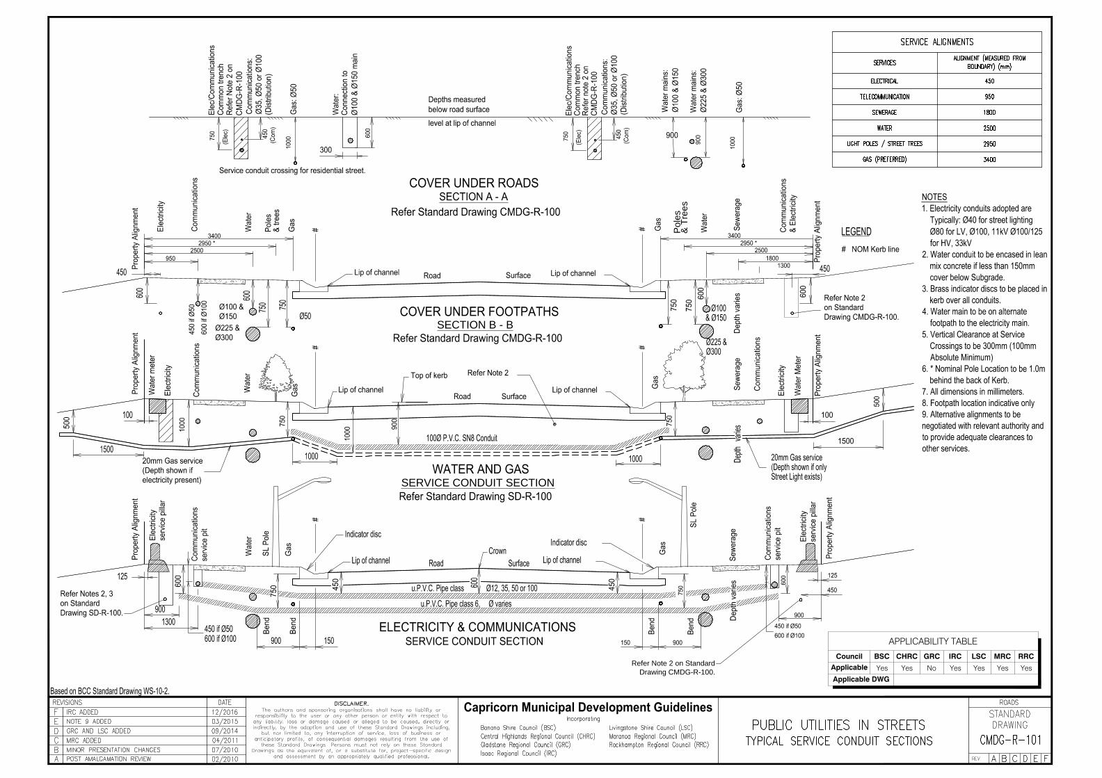
1. The alignment and depths of existing services shall be proven on site
by consultation with the relevant service authorities prior to any excavation
and shall not be inferred from this drawing.
2. Various configurations of trench width and conduit numbers/diameters
exist for both electricity and common trench arrangements with
communication companies.
3. Refer Standard Drawing CMDG-R-101 for sectional views.
4. Water connection point to be on alternate front boundary to the
electricity connection point
5. Water main to be on alternate footpath to the electricity main
6. Conduit trenches are to be filled with sand.
7. Skewed conduits are not favored, if required conduits should be from
pillar to pillar.
8. Preferred Tree planting location to be Mid-Property Alignment
9. Location and width of Footpath indicative only.
10. All dimensions in millimeters
11. Alternative alignments to be negotiated with relevant authority and to
provide adequate clearances to other services.
LEGEND
Possible Street Light *
Preferred Tree Location
Preferred Tree Location
Possible Street Light *
Possible Street Light *
Possible Street Light *
* Nominal Pole/Tree Location to be
1.0m behind back of Kerb.
APPLICABILITY TABLE
Council BSC CHRC GRC IRC LSC MRC RRC
Applicable Yes Yes No Yes Yes Yes Yes
Applicable DWG
SERVICE ALIGNMENTS
SERVICES
ALIGNMENT (MEASURED
FROM BOUNDARY) (mm)
ELECTRICAL 450
TELECOMMUNICATION 950
SEWERAGE 1800
WATER 2500
LIGHT POLES / STREET TREES 2950
GAS (PREFERRED)
3400

APPLICABILITY TABLE
Council BSC CHRC GRC IRC LSC MRC RRC
Applicable No No Yes No No No No
Applicable DWG CMDG-R-100
C
L
SERVICE ENTRY TO ADJOINING PROPERTIES
BEDDING SAND
ORANGE CONDUIT
WARNING TAPE
900
450
750
Min
375
450
450
750
Min
600
Min
900
Min
25 Min
900 Min
100 Min
500 Min
450
900
GAS
WARNING
TAPE
GAS
SERVICE
(10mm NB)
FUTURE
EXCAVATION
ACCESS FOR
WATER MAIN
FUTURE
EXCAVATION
ACCESS FOR LV
CABLE
GAS
TRACER
WIRE
KERB MARKER
(INDICATING
LOCATION AND TYPE
OF SERVICE
CONDUIT WHERE
APPLICABLE EG.
WATER, GAS,
TELSTRA, ELEC.)
SEWER MH OFFSET
150mm FROM SEWER
LINE WHERE POSSIBLE.
COARSE GRAINED SAND
BACKFILL TO COMMON
TRENCH AND AROUND
DISTRIBUTION FEED
POINTS
(SAND SHOWN SHADED)
JOINT TRENCH 300MM
OFF BOUNDARY
JOINT TRENCHING NOTES:
GENERAL
1. TRENCH WIDTH OF 900mm IS A MINIMUM. THE TRENCH WIDTH SHALL BE
WIDENED FOR CUL-DE-SAC SITUATIONS. LARGER DIAMETER WATER MAINS
AND ANY OTHER SITUATIONS WHERE MINIMUM CLEARANCES CANNOT BE
MAINTAINED.
2. SERVICES ENTRY MAY BE SPLIT BETWEEN EITHER BOUNDRY PEG TO
SATISFACTION OF CITY ENGINEER
3. FUTURE EXCAVATION AREAS MUST BE CLEAR OF ALL OTHER SERVICES.
4. DIMENSIONS INDICATE CLEAN TRENCH WIDTHS.
5. EXCAVATIONS ACROSS ROADWAYS TO BE FILLED AND COMPACTED TO
COUNCIL REQUIREMENTS.
POWER CABLE - CAPELEC REQUIREMENTS
6. CONDUITS: - CLASS 6 ORANGE IS SUITABLE FOR UNDERGROUND
RESIDENTIAL SUBDIVISIONS - HEAVY DUTY CONDUIT IN ACCORDANCE WITH
A.S. 2053-1984 SHALL BE USED UNDER ALL MAIN ROADS.
GAS MAIN - GAS CORP. QLD LTD REQUIREMENTS
7. MARKER TAPE OVER SERVICE
8. KERB MARKER @ CROSSING TO INDICATE SERVICE LOCATION.
9. WHERE GAS SERVICE COINCIDES WITH WATER SERVICE, GAS MUST BE
LOCATED UNDER WATER MAIN.
WATER - COUNCIL REQUIREMENTS
10. WHERE THRUST BLOCKS ARE REQUIRED ON THE WATER MAIN, THE
ELECTRICITY CABLE SHALL BE LOWERED TO GIVE 150mm MIN. VERTICAL
CLEARANCE TO WATER MAIN.
11. MINIMUM 100mm SAND BEDDING SHALL SURROUND WATER
MAIN.
TELSTRA REQUIREMENTS
12. TELSTRA CONDUIT (MAXIMUM DIAMETER 50mm) TO BE LAID
TO TELECOM REQUIREMENTS.
13. P4 TELSTRA PITS ARE NOT TO BE USED EVEN FOR ROAD
CROSSINGS. THE TELSTRA CONDUIT IS TO BE LOWERED
OVER THE DISTANCE FROM THE END OF THE PIT TO THE
KERB MAINTAINING THE ABOVE STATED MINIMUM
SEPARATIONS FROM POWER.
14. CRUSHER DUST OR SAND IS TO BE SPREAD OVER THE
TELSTRA CONDUIT TO A DEPTH OF 100mm IF THE EXCAVATED
SOIL HAS A HIGH ROCK CONTENT.
15. IN SOME CASES, PARTICULARLY WHERE BLASTING IS
REQUIRED TO OPEN A TRENCH, IT MAY BE NECESSARY TO
ALTER THE ABOVE TRENCH DESIGNS TO INCLUDE TELSTRA
MAIN CONDUIT. THIS IS TO AVOID DAMAGE TO EXISTING
SERVICES DUE TO TRENCH EXCAVATIONS ON TELSTRA'S MAIN
CONDUIT ALIGNMENT.
& T
rees
Poles
Refer Note 2 on Standard
Drawing CMDG-R-100.
SECTION B - B
SERVICE CONDUIT SECTION
APPLICABILITY TABLE
Council BSC CHRC GRC IRC LSC MRC RRC
Applicable Yes Yes No Yes Yes Yes Yes
Applicable DWG

APPLICABILITY TABLE
Council BSC CHRC GRC IRC LSC MRC RRC
Applicable No No Yes No No No No
Applicable DWG CMDG-R-101
*
.
.
.
.
.
..
.
.
.
.
.
..
.
.
.
.
.
.
.
.
.
..
.
..
W
S
W
NOTES
1. No pits or manhole covers for power, telephone, water, sewerage and drainage services
shall be placed within the carriageway unless approved by the director of technical services.
2. Trimming and compaction of the subgrade is to be completed and approved before
excavation for the service conduits is commenced. excavation material shall be thrown on
the footpath and not on the subgrade.
3. Service conduit alternatives:-100 Ø Concrete/FR pipes (S.F.) Class C or S (R.R.J.) 100Ø
uPVC, Class 12
4. On wider footpaths, positions of services except stormwater, and signs are to be fixed by
measurement from the property alignment.
5. Where practical, stormwater drainage is to be located between lip of channel and space
allocated for poles. Sub-soil drainage is to be located under kerb & channel when required.
6. Location and width of concrete footpath where ordered shall be determined by the director of
technical services.
7. For service conduits other than water, similar construction is to be utilised but with minimum
depths of 750mm or as specified by relevant authorities.
4.25
0.8
0.5
0.3
0.9 2.0 #
1.5
Joint trench
Refer to CMDG-R-100A
0.3 Offset0.9
Min.
Concrete
Footpath
LocationBlock ends to
satisfaction of engineer.
0.1min
Joint trench
Refer to CMDG-R-100A
Pavement
Indicator Discs
4.25
0.8
0.5
0.3
2.4
1.5
0.3
0.9
Min.
Dependant on the
width of footpath
road as per hierarchy
or permit condition
Fixed width
@ 1.2m
*
*
#