g1000 synthetic vision & pathways option -...
TRANSCRIPT
190-00545-10 March, 2008 Revision 2
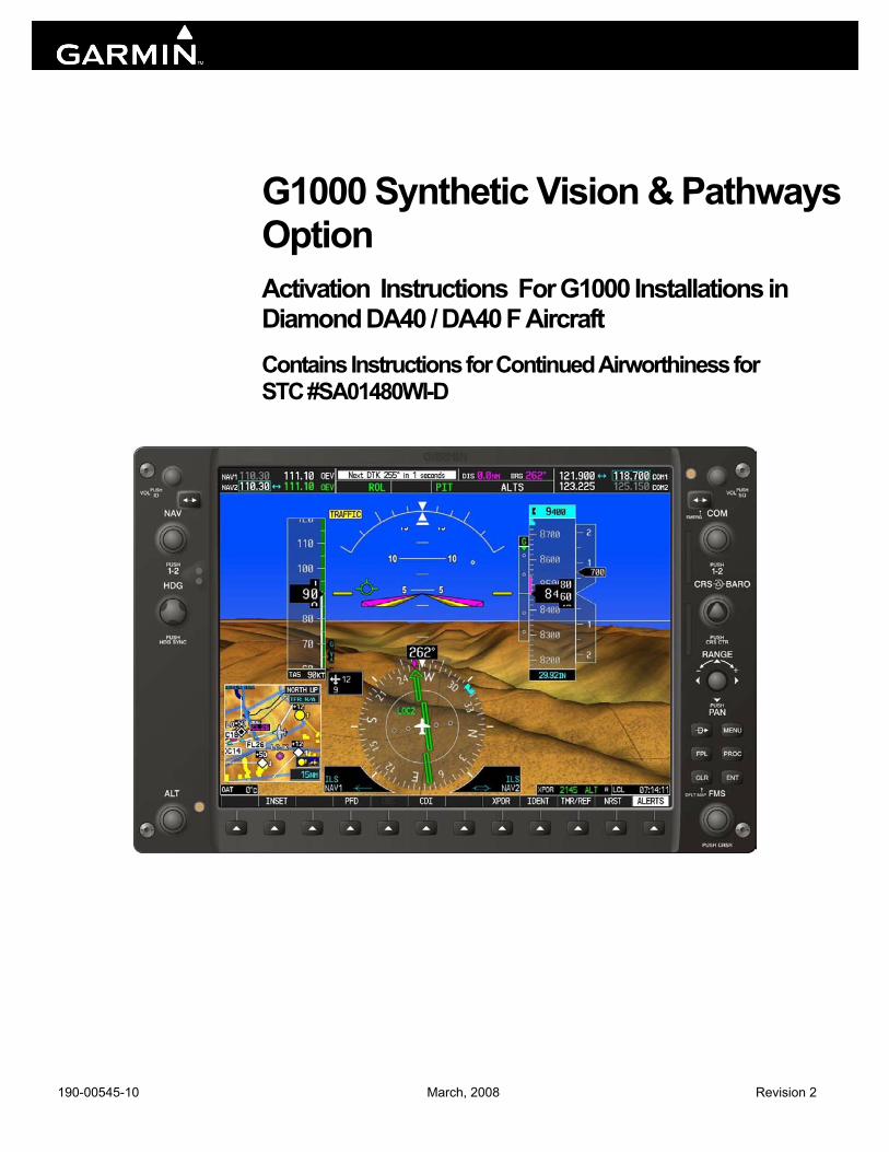
G1000 Synthetic Vision & Pathways Option Activation Instructions For G1000 Installations in Diamond DA40 / DA40 F Aircraft Contains Instructions for Continued Airworthiness for STC #SA01480WI-D
Page A G1000 SVS / Pathways STC Activation & Checkout Revision 2 190-00545-10
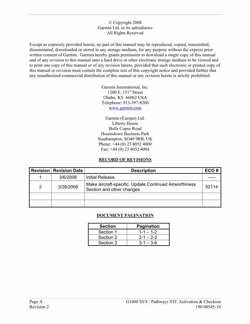
© Copyright 2008 Garmin Ltd. or its subsidiaries
All Rights Reserved Except as expressly provided herein, no part of this manual may be reproduced, copied, transmitted, disseminated, downloaded or stored in any storage medium, for any purpose without the express prior written consent of Garmin. Garmin hereby grants permission to download a single copy of this manual and of any revision to this manual onto a hard drive or other electronic storage medium to be viewed and to print one copy of this manual or of any revision hereto, provided that such electronic or printed copy of this manual or revision must contain the complete text of this copyright notice and provided further that any unauthorized commercial distribution of this manual or any revision hereto is strictly prohibited.
Garmin International, Inc. 1200 E. 151st Street
Olathe, KS 66062 USA Telephone: 913-397-8200
www.garmin.com
Garmin (Europe) Ltd. Liberty House
Bulls Copse Road Hounsdown Business Park
Southampton, SO40 9RB, UK Phone: +44 (0) 23 8052 4000
Fax: +44 (0) 23 8052 4004
RECORD OF REVISIONS
Revision Revision Date Description ECO #1 3/6/2008 Initial Release. -----
2 3/28/2008 Make aircraft-specific. Update Continued Airworthiness Section and other changes. 52114
DOCUMENT PAGINATION
Section Pagination
Section 1 1-1 – 1-2 Section 2 2-1 – 2-2 Section 3 3-1 – 3-6
G1000 SVS / Pathways STC Activation & Checkout Page 1-1 190-00545-10 Revision 2
1 INTRODUCTION 1.1 Scope This document presents activation procedures and Instructions for Continued Airworthiness required for the optional Synthetic Vision and Pathways feature in the G1000 Integrated Cockpit System for DA40/DA40F aircraft, as installed by STC #SA01480WI-D. This manual does not constitute a complete set of G1000 Post Installation or Maintenance procedures. The procedures in this manual are to be performed on a completed G1000 installation only, per the requirements of the STC Master Drawing List, 005-00442-02.
Table 1-1. Reference Documents Part Number Document
005-00442-02 STC Master Drawing List
190-00545-01* G1000 System Maintenance Manual – Diamond DA40 & DA40F, With GFC 700 or KAP140 AFCS*
190-00492-15 Airplane Flight Manual Supplement, Synthetic Vision & Pathways Option *Existing approved G1000/DA40 ICA under the prerequisite STC #SA01444WI-D.
1.2 Organization This manual is divided into two sections as follows: Section 2: SVS/Pathways Activation Provides the requirements and instructions to activate the G1000 Synthetic Vision & Pathways Option. Section 3: Continued Airworthiness Defines the continued airworthiness requirements of the SVS/Pathways software feature.
Page 1-2 G1000 SVS / Pathways STC Activation & Checkout Revision 2 190-00545-10
This page intentionally left blank.
G1000 SVS / Pathways STC Activation & Checkout Page 2-1 190-00545-10 Revision 2
2 SVS / Pathways Activation This section provides the requirements and instructions necessary to unlock the G1000 Synthetic Vision / Pathways feature.
Baseline Software:
The Garmin Synthetic Vision and Pathways feature requires GDU software version 9.01 or later to be installed with the DA40-specific software/configuration image prior to activation. See the STC Master Drawing List for specific installation requirements.
Database Cards:
The Garmin Synthetic Vision and Pathways feature requires 9 arc-second high resolution terrain databases to function.
Each G1000 display must be equipped with the P/N 010-00330-43 Terrain/Obstacle/SafeTaxi database card installed in the lower slot.
SVS / Pathways Unlock Card:
The following unlock card is required to activate the SVS / Pathways feature for G1000/DA40 installations:
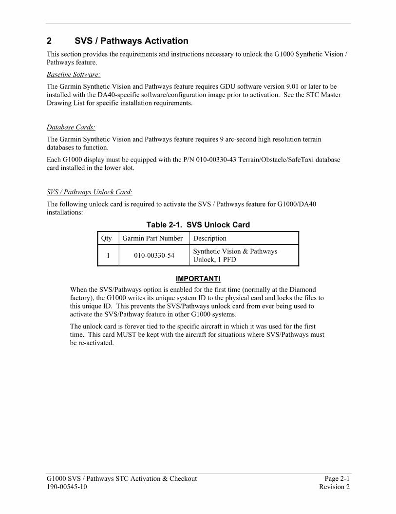
Table 2-1. SVS Unlock Card Qty Garmin Part Number Description
1 010-00330-54 Synthetic Vision & Pathways Unlock, 1 PFD
IMPORTANT!
When the SVS/Pathways option is enabled for the first time (normally at the Diamond factory), the G1000 writes its unique system ID to the physical card and locks the files to this unique ID. This prevents the SVS/Pathways unlock card from ever being used to activate the SVS/Pathway feature in other G1000 systems.
The unlock card is forever tied to the specific aircraft in which it was used for the first time. This card MUST be kept with the aircraft for situations where SVS/Pathways must be re-activated.
Page 2-2 G1000 SVS / Pathways STC Activation & Checkout Revision 2 190-00545-10
2.1 SVS Activation Procedure
Activate the SVS/Pathways feature by performing the following steps:
1. Pull the MFD and PFD circuit breakers.
2. Turn on the ground power unit, if used.
3. Turn on the BAT side master switch.
4. Turn on the AVIONICS MASTER switch. At this moment, all G1000 equipment should be receiving power, except the PFD and MFD.
5. A special SVS Unlock card is required to activate this feature, refer to Table 2-1. Insert this card in the upper slot of the pilot’s side PFD.
6. While holding the ENT key on the MFD, restore power by closing the MFD circuit breaker.
7. When the words appear in the upper left corner of the MFD, release the ENT key.
8. Repeat Steps 6 and 7 for the PFD.
9. On the PFD, go to the System Upload page using the FMS knob.
10. Activate the cursor. Use the small FMS knob to select CONFIGURATION FILES in the AIRFRAME field and press the ENT key.
11. Highlight the FILE field. Use the small FMS knob to select the “Enable SVS” option and press the ENT key. Once the option is selected the configuration files in the PRODUCT field will be displayed. All files should be checked. If not, press the CHK ALL softkey.
12. Press the LOAD softkey.
13. Monitor the status of the upload. When the upload is finished, press the ENT key to acknowledge the upload complete confirmation.
14. View the SUMMARY field and ensure that the item is ‘COMPLETE’.
15. De-activate the cursor.
16. Power down the system and remove the SVS Unlock card from the PFD.
2.2 SVS / Pathways Installation Verification
1. Apply power to the G1000 system. Allow the AHRS and magnetometer systems to stabilize and align. Verify that air data information becomes valid on the PFD. Check the MFD AUX – System Status page to verify GPS signals acquisition.
2. Press the ALERTS softkey on the PFD and verify no database, manifest, or configuration errors exist.
3. Press the PFD softkey. Verify a SYN VIS softkey is shown in the lower left corner of the display.
4. Press the SYN VIS softkey, then press the SYN TERR softkey, to activate the Synthetic Vision terrain display feature. Verify that the traditional blue/brown attitude depiction is replaced with the Synthetic Vision rendering within 2-3 minutes of activation.
5. Installation is complete. Be sure to keep the SVS / Pathways unlock card with the aircraft for future use.
G1000 SVS / Pathways STC Activation & Checkout Page 3-1 190-00545-10 Revision 2
3 Continued Airworthiness This section provides Instruction for Continued Airworthiness for the G1000 Synthetic Vision & Pathways Option. This document satisfies the requirements for continued airworthiness as defined by 14 CFR Part 23.1529 and Part 23 Appendix G. Information in this section is required to maintain the continued airworthiness of the G1000 SVS/Pathways option. 3.1.1 Applicability This document applies to all Diamond Aircraft Industries, Inc., Model DA 40 and DA 40 F aircraft equipped with the G1000 which have the optional SVS/Pathways feature activated per STC #SA01480WI-D. Modification of an aircraft by this Supplemental Type Certificate (STC) obligates the aircraft operator to include the maintenance information provided by this document in the operator’s Aircraft Maintenance Manual and the operator’s Aircraft Scheduled Maintenance Program.
3.2 Airworthiness Limitations There are no airworthiness limitations associated with the activation of the optional G1000 SVS / Pathways feature under STC #SA01480WI-D. The previously approved Instructions for Continued Airworthiness defined by the prerequisite STC #SA01444WI-D remain valid and applicable for all other maintenance and ICA aspects of the G1000 and optional GFC 700 systems. The Airworthiness Limitations section is FAA-approved and specifies maintenance required under §§ 43.16 and 91.403 of Title 14 of the Code of Federal Regulations, unless an alternative program has been FAA-approved.
Page 3-2 G1000 SVS / Pathways STC Activation & Checkout Revision 2 190-00545-10
3.2.1 Definitions/Abbreviations AFMS – Airplane Flight Manual Supplement FPM – Flight Path Marker GDU – Garmin Display Unit GPS – Global Positioning System GTX – Garmin Transponder ICA – Instructions for Continued Airworthiness MFD – Multi-Function Flight Display PFD – Primary Flight Display STC – Supplemental Type Certificate SVS – Synthetic Vision System 3.2.2 Units of Measure Units of measure are not applicable to this STC. 3.3 Distribution This document is required for maintaining the continued airworthiness of aircraft equipped with this STC. Revisions to this document will be made by Garmin and will be distributed by Garmin per standard documentation revision procedures.
For the latest revision to this document, check Garmin’s web site at: www.garmin.com/ and click on ‘Dealers Only’.
NOTE
Only Garmin-authorized dealers and service centers are given access to the Dealer portion of the Web Site. If you do not have a Dealer Password, contact Garmin directly to obtain the latest revision of this document.
G1000 SVS / Pathways STC Activation & Checkout Page 3-3 190-00545-10 Revision 2
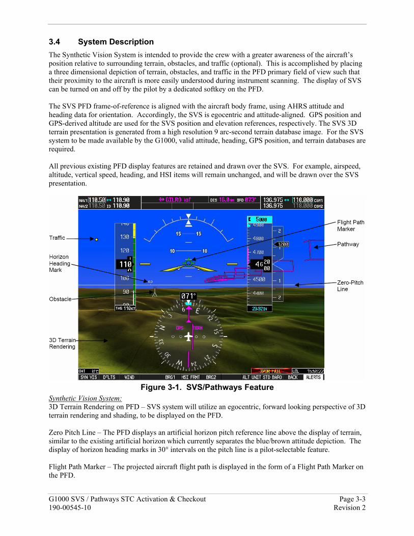
3.4 System Description The Synthetic Vision System is intended to provide the crew with a greater awareness of the aircraft’s position relative to surrounding terrain, obstacles, and traffic (optional). This is accomplished by placing a three dimensional depiction of terrain, obstacles, and traffic in the PFD primary field of view such that their proximity to the aircraft is more easily understood during instrument scanning. The display of SVS can be turned on and off by the pilot by a dedicated softkey on the PFD. The SVS PFD frame-of-reference is aligned with the aircraft body frame, using AHRS attitude and heading data for orientation. Accordingly, the SVS is egocentric and attitude-aligned. GPS position and GPS-derived altitude are used for the SVS position and elevation references, respectively. The SVS 3D terrain presentation is generated from a high resolution 9 arc-second terrain database image. For the SVS system to be made available by the G1000, valid attitude, heading, GPS position, and terrain databases are required. All previous existing PFD display features are retained and drawn over the SVS. For example, airspeed, altitude, vertical speed, heading, and HSI items will remain unchanged, and will be drawn over the SVS presentation.
Figure 3-1. SVS/Pathways Feature
Synthetic Vision System: 3D Terrain Rendering on PFD – SVS system will utilize an egocentric, forward looking perspective of 3D terrain rendering and shading, to be displayed on the PFD. Zero Pitch Line – The PFD displays an artificial horizon pitch reference line above the display of terrain, similar to the existing artificial horizon which currently separates the blue/brown attitude depiction. The display of horizon heading marks in 30° intervals on the pitch line is a pilot-selectable feature. Flight Path Marker – The projected aircraft flight path is displayed in the form of a Flight Path Marker on the PFD.
Page 3-4 G1000 SVS / Pathways STC Activation & Checkout Revision 2 190-00545-10
Display of Traffic – Traffic data from existing certified TIS, provided by the G1000 GTX 33 Mode-S transponder, is used to generate on-screen traffic symbols. Display of Land-based Objects – Obstacles, runways, water bodies, and other land features are displayed on the PFD. Pathways: SVS / Pathways are a pilot-selectable feature. The display of SVS can be turned on and off by the pilot by a dedicated softkey on the PFD. The display of Pathways requires that the 3D Terrain feature be displayed (i.e. SYN TERR softkey pressed). When active, the Pathway is displayed on the PFD and will show flight path information in the form of a virtual 3D flight path, composed of rectangular elements which form a tunnel. The depiction of this pathway is derived from the existing FMS navigation capabilities of the G1000, and the display will be consistent with that of the active flight plan shown on the MFD.
3.4.1 Control & Operation SVS/Pathways is an embedded software feature of the G1000 and is controlled by using PFD softkeys. Specific details on operating the SVS/Pathways feature can be found in the Synthetic Vision & Pathways AFMS specified in Table 1-1.
3.5 Servicing Information SVS/Pathways is a non-serviceable software feature which is either active or inactive in the G1000 system. Section 2.2 provides a check to determine the state of the SVS/Pathways feature.
There are no inspection intervals required for the SVS/Pathways feature.
Reactivation may be required following normal maintenance procedures. See Section 3.7.
3.5.1 Recommended Tools No tools are required to activate and maintain the SVS/Pathways feature.
G1000 SVS / Pathways STC Activation & Checkout Page 3-5 190-00545-10 Revision 2
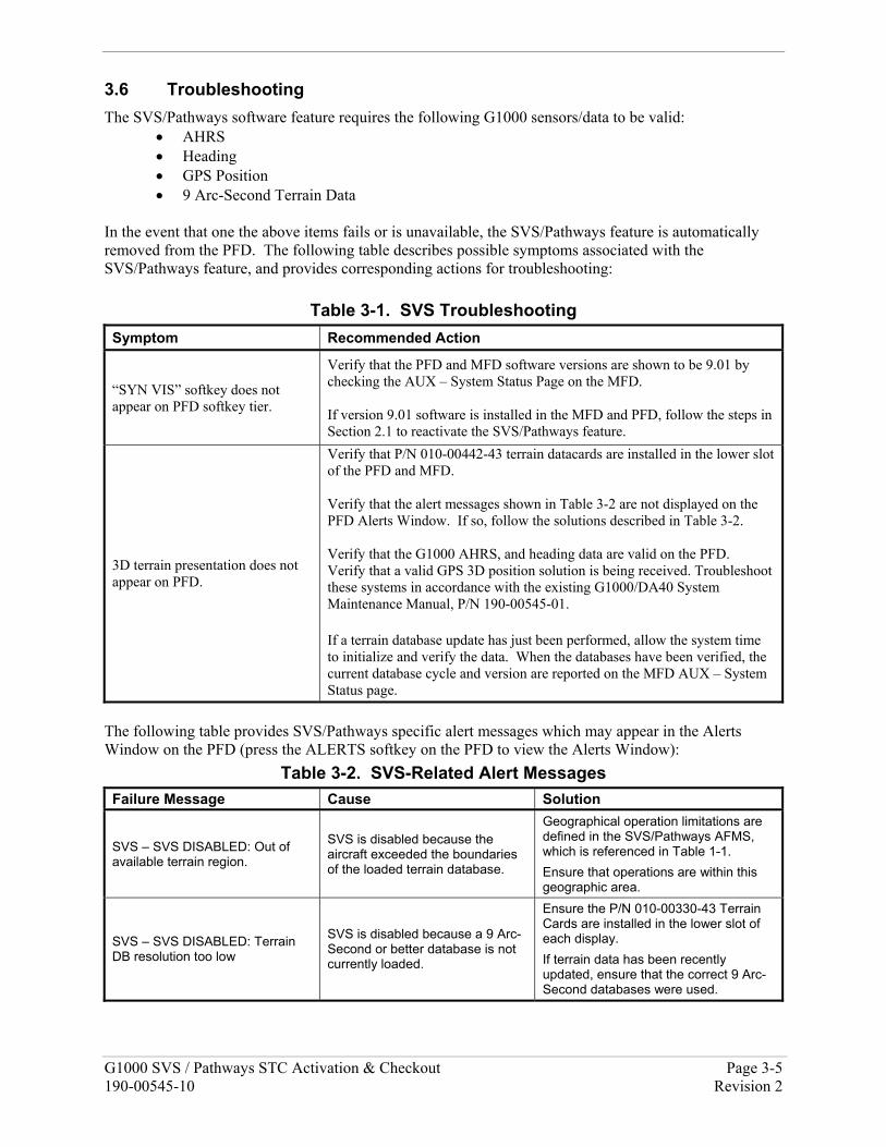
3.6 Troubleshooting The SVS/Pathways software feature requires the following G1000 sensors/data to be valid:
• AHRS • Heading • GPS Position • 9 Arc-Second Terrain Data
In the event that one the above items fails or is unavailable, the SVS/Pathways feature is automatically removed from the PFD. The following table describes possible symptoms associated with the SVS/Pathways feature, and provides corresponding actions for troubleshooting:
Table 3-1. SVS Troubleshooting Symptom Recommended Action
“SYN VIS” softkey does not appear on PFD softkey tier.
Verify that the PFD and MFD software versions are shown to be 9.01 by checking the AUX – System Status Page on the MFD. If version 9.01 software is installed in the MFD and PFD, follow the steps in Section 2.1 to reactivate the SVS/Pathways feature.
3D terrain presentation does not appear on PFD.
Verify that P/N 010-00442-43 terrain datacards are installed in the lower slot of the PFD and MFD. Verify that the alert messages shown in Table 3-2 are not displayed on the PFD Alerts Window. If so, follow the solutions described in Table 3-2. Verify that the G1000 AHRS, and heading data are valid on the PFD. Verify that a valid GPS 3D position solution is being received. Troubleshoot these systems in accordance with the existing G1000/DA40 System Maintenance Manual, P/N 190-00545-01. If a terrain database update has just been performed, allow the system time to initialize and verify the data. When the databases have been verified, the current database cycle and version are reported on the MFD AUX – System Status page.
The following table provides SVS/Pathways specific alert messages which may appear in the Alerts Window on the PFD (press the ALERTS softkey on the PFD to view the Alerts Window):
Table 3-2. SVS-Related Alert Messages Failure Message Cause Solution
SVS – SVS DISABLED: Out of available terrain region.
SVS is disabled because the aircraft exceeded the boundaries of the loaded terrain database.
Geographical operation limitations are defined in the SVS/Pathways AFMS, which is referenced in Table 1-1. Ensure that operations are within this geographic area.
SVS – SVS DISABLED: Terrain DB resolution too low
SVS is disabled because a 9 Arc-Second or better database is not currently loaded.
Ensure the P/N 010-00330-43 Terrain Cards are installed in the lower slot of each display. If terrain data has been recently updated, ensure that the correct 9 Arc-Second databases were used.
Page 3-6 G1000 SVS / Pathways STC Activation & Checkout Revision 2 190-00545-10
3.7 Removal & Replacement SVS/Pathways is a non-serviceable software feature and cannot be physically removed or replaced in the G1000. 3.7.1 SVS/Pathways Reactivation Criteria Certain G1000 maintenance activities will require the SVS/Pathways feature to be re-activated. Specifically, any time the default AIRFRAME configuration file is reloaded to the G1000, the SVS/Pathways feature ‘activation’ is lost. See Section 3.5 of the existing G1000/DA40 System Maintenance manual, listed in Table 1-1 for detailed information regarding G1000 configuration files. The following specific maintenance scenarios will require re-activation of the SVS/Pathways feature:
• Software and configuration files is completely re-loaded to the G1000 system.
• Software and configuration files specific to the PFD were re-loaded, either as the result of troubleshooting procedures or of complete PFD replacement.
In the event one of these scenarios occurs, the technician must reactivate and verify the SVS/Pathways feature following the steps outlined in Sections 2.1 and 2.2.
3.8 Return to Service The verification steps provided in Section 2.2 must be used to verify the SVS/Pathways feature has been successfully activated and is functioning properly.