g200 flite manual
TRANSCRIPT

Electrical network managementMV substation control unit
Merlin Gerin Easergy RangeWireless Communicating indicator
FLITE116 - G200 - DNP3 user’s manual
INTRODUCTION....................................................................................................................................................................................................3
GENERAL NOTES ...................................................................................................................................................................................................3PRODUCT REFERENCES...........................................................................................................................................................................................3
PART 1 - G200.........................................................................................................................................................................................................4
GENERAL DESCRIPTION ..........................................................................................................................................................................................5Introduction .....................................................................................................................................................................................................5Functions.........................................................................................................................................................................................................5General specifications.......................................................................................................................................................................................6
G2PF...................................................................................................................................................................................................................7Principle of operation .......................................................................................................................................................................................7Product description...........................................................................................................................................................................................8Electrical specifications...................................................................................................................................................................................11Dimensions....................................................................................................................................................................................................12I/O Wiring .....................................................................................................................................................................................................12
G2GF .................................................................................................................................................................................................................13Principle of operation .....................................................................................................................................................................................13Product description.........................................................................................................................................................................................14Electrical specification ....................................................................................................................................................................................14Dimensions....................................................................................................................................................................................................14
G2SF..................................................................................................................................................................................................................15Principle of operation .....................................................................................................................................................................................15Product description.........................................................................................................................................................................................16Electrical specifications...................................................................................................................................................................................16Dimensions....................................................................................................................................................................................................17
PART 2 – FLITE...................................................................................................................................................................................................18
FUNCTIONS.........................................................................................................................................................................................................19Introduction ...................................................................................................................................................................................................19Operations performed .....................................................................................................................................................................................19
TIMING DIAGRAM................................................................................................................................................................................................20INSTALLATION ....................................................................................................................................................................................................22
Power supply..................................................................................................................................................................................................22Test/reset feature and maintenance ...................................................................................................................................................................22Installation.....................................................................................................................................................................................................22
GENERAL SPECIFICATIONS....................................................................................................................................................................................23MECHANICAL SPECIFICATIONS..............................................................................................................................................................................24
PART 3 - INSTALLATION...................................................................................................................................................................................25
FLITE INSTALLATION ..........................................................................................................................................................................................26EXCLUSION ZONES...............................................................................................................................................................................................27RADIO OR CELLULAR ANTENNA.............................................................................................................................................................................28SIM CARD FOR GSM/ GPRS COMMUNICATIONS.....................................................................................................................................................29
Introduction to GSM/ GPRS networks...............................................................................................................................................................29G200 MOUNTING .................................................................................................................................................................................................30
G2PF ............................................................................................................................................................................................................30G2GF ............................................................................................................................................................................................................34G2SF.............................................................................................................................................................................................................35
PART 4 - COMMISSIONING ...............................................................................................................................................................................36
G200 CONFIGURATION TOOLS...............................................................................................................................................................................37Hardware required .........................................................................................................................................................................................37Connecting the computer.................................................................................................................................................................................37Configuring the unit........................................................................................................................................................................................37
CPU CONFIGURATION ..........................................................................................................................................................................................38G200 main menu ............................................................................................................................................................................................38G200 long range communication settings..........................................................................................................................................................40Time setup .....................................................................................................................................................................................................46Protocol profile settings..................................................................................................................................................................................47Alarm and storage settings...............................................................................................................................................................................48Relay parameters (Only for G2SF): ..................................................................................................................................................................52
FLITE CONFIGURATION .........................................................................................................................................................................................53Short range radio communication settings.........................................................................................................................................................53Fault detection parameter settings....................................................................................................................................................................54
PART 5 - MAINTENANCE....................................................................................................................................................................................55
INTRODUCTION....................................................................................................................................................................................................56General information........................................................................................................................................................................................56Connecting the computer and using the software ................................................................................................................................................56
DIAGNOSTICS ......................................................................................................................................................................................................57Equipment states.............................................................................................................................................................................................57DNP3 protocol analysis...................................................................................................................................................................................58Events display ................................................................................................................................................................................................58Current measurement display.........................................................................................................................................................................58FLITE radio analysis ......................................................................................................................................................................................59FLITE counters ..............................................................................................................................................................................................59
Schneider Electric - NT00089EN-04 Easergy G200 3
Introduction General Notes
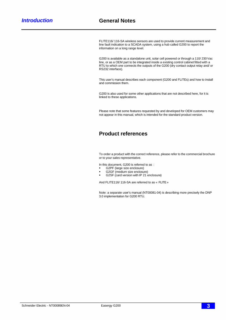
FLITE116/ 116-SA wireless sensors are used to provide current measurement andline fault indication to a SCADA system, using a hub called G200 to report theinformation on a long range level.
G200 is available as a standalone unit, solar cell powered or through a 110/ 230 Vacline, or as a OEM part to be integrated inside a existing control cabinet fitted with aRTU to which one connects the outputs of the G200 (dry contact output relay and/ orRS232 interface).
This user’s manual describes each component (G200 and FLITEs) and how to installand commission them.
G200 is also used for some other applications that are not described here, for it islinked to these applications.
Please note that some features requested by and developed for OEM customers maynot appear in this manual, which is intended for the standard product version.
Product references
To order a product with the correct reference, please refer to the commercial brochureor to your sales representative.
In this document, G200 is referred to as :§ G2PF (large size enclosure)§ G2GF (medium size enclosure)§ G2SF (card version with IP 21 enclosure)
And FLITE116/ 116-SA are referred to as « FLITE »
Note: a separate user’s manual (NT00081-04) is describing more precisely the DNP3.0 implementation for G200 RTU.

Schneider Electric - NT00089EN-04 Easergy G200 4
Part 1 - G200
Part 1 - G200
Schneider Electric - NT00089EN-04 Easergy G200 5
Part 1 – G200 General description
Introduction
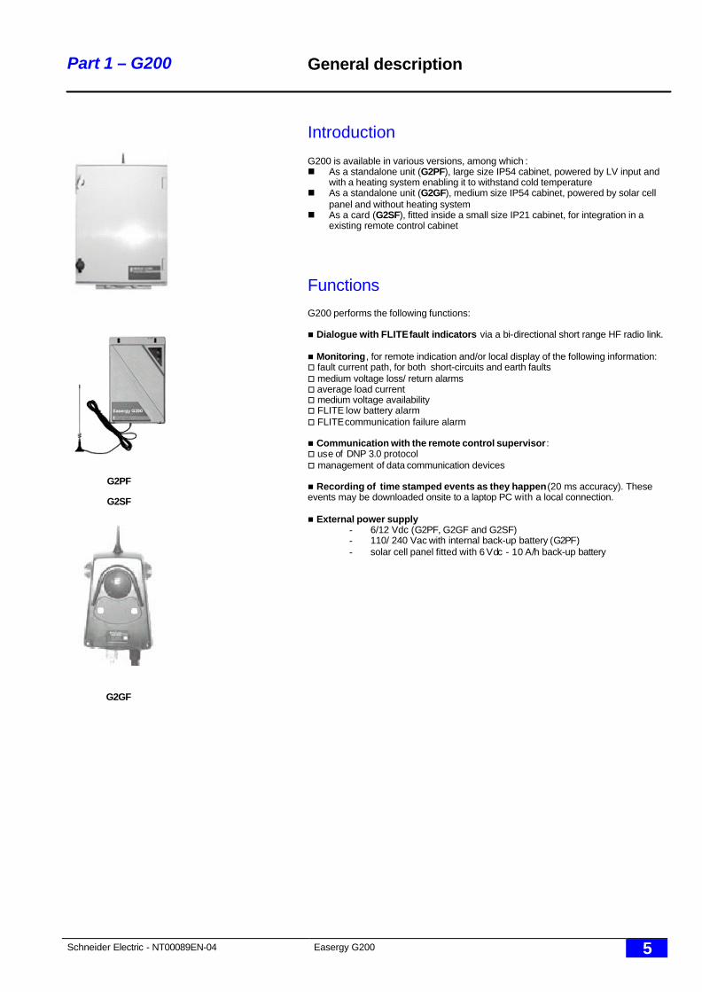
G200 is available in various versions, among which :n As a standalone unit (G2PF), large size IP54 cabinet, powered by LV input and
with a heating system enabling it to withstand cold temperaturen As a standalone unit (G2GF), medium size IP54 cabinet, powered by solar cell
panel and without heating systemn As a card (G2SF), fitted inside a small size IP21 cabinet, for integration in a
existing remote control cabinet
Functions
G200 performs the following functions:
n Dialogue with FLITE fault indicators via a bi-directional short range HF radio link.
n Monitoring, for remote indication and/or local display of the following information:o fault current path, for both short-circuits and earth faultso medium voltage loss/ return alarmso average load currento medium voltage availabilityo FLITE low battery alarmo FLITE communication failure alarm
n Communication with the remote control supervisor:o use of DNP 3.0 protocolo management of data communication devices
n Recording of time stamped events as they happen (20 ms accuracy). Theseevents may be downloaded onsite to a laptop PC with a local connection.
n External power supply- 6/12 Vdc (G2PF, G2GF and G2SF)- 110/ 240 Vac with internal back-up battery (G2PF)- solar cell panel fitted with 6 Vdc - 10 A/h back-up battery
G2PF
G2GF
G2SF
Schneider Electric - NT00089EN-04 Easergy G200 6
Part 1 – G200 General description
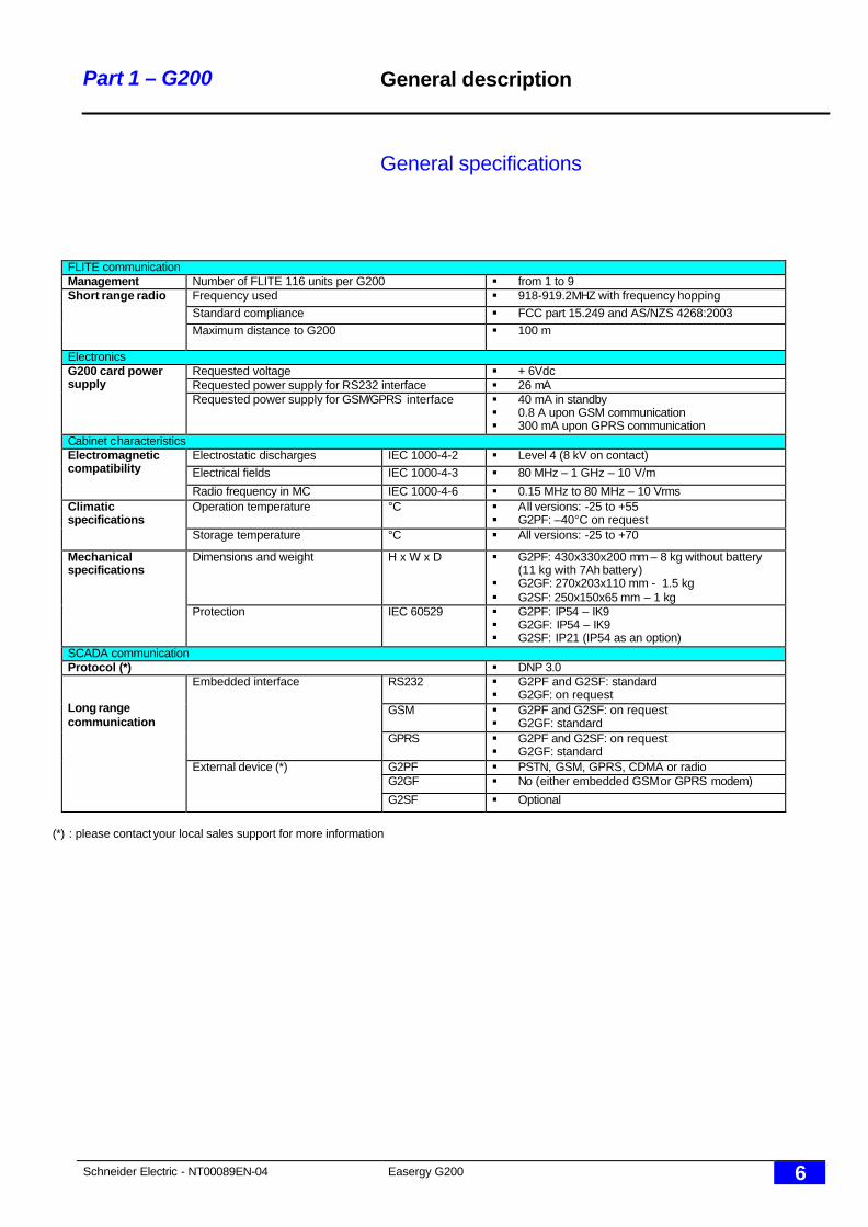
General specifications
FLITE communicationManagement Number of FLITE 116 units per G200 § from 1 to 9
Frequency used § 918-919.2MHZ with frequency hoppingStandard compliance § FCC part 15.249 and AS/NZS 4268:2003
Short range radio
Maximum distance to G200 § 100 m
ElectronicsRequested voltage § + 6VdcRequested power supply for RS232 interface § 26 mA
G200 card powersupply
Requested power supply for GSM/GPRS interface § 40 mA in standby§ 0.8 A upon GSM communication§ 300 mA upon GPRS communication
Cabinet characteristicsElectrostatic discharges IEC 1000-4-2 § Level 4 (8 kV on contact)Electrical fields IEC 1000-4-3 § 80 MHz – 1 GHz – 10 V/m
Electromagneticcompatibility
Radio frequency in MC IEC 1000-4-6 § 0.15 MHz to 80 MHz – 10 VrmsOperation temperature °C § All versions: -25 to +55
§ G2PF: –40°C on requestClimaticspecifications
Storage temperature °C § All versions: -25 to +70
Dimensions and weight H x W x D § G2PF: 430x330x200 mm – 8 kg without battery(11 kg with 7Ah battery)
§ G2GF: 270x203x110 mm - 1.5 kg§ G2SF: 250x150x65 mm – 1 kg
Mechanicalspecifications
Protection IEC 60529 § G2PF: IP54 – IK9§ G2GF: IP54 – IK9§ G2SF: IP21 (IP54 as an option)
SCADA communicationProtocol (*) § DNP 3.0
RS232 § G2PF and G2SF: standard§ G2GF: on request
GSM § G2PF and G2SF: on request§ G2GF: standard
Embedded interface
GPRS § G2PF and G2SF: on request§ G2GF: standard
G2PF § PSTN, GSM, GPRS, CDMA or radioG2GF § No (either embedded GSM or GPRS modem)
Long rangecommunication
External device (*)
G2SF § Optional
(*) : please contact your local sales support for more information
Schneider Electric - NT00089EN-04 Easergy G200 7
Part 1 – G200 G2PF
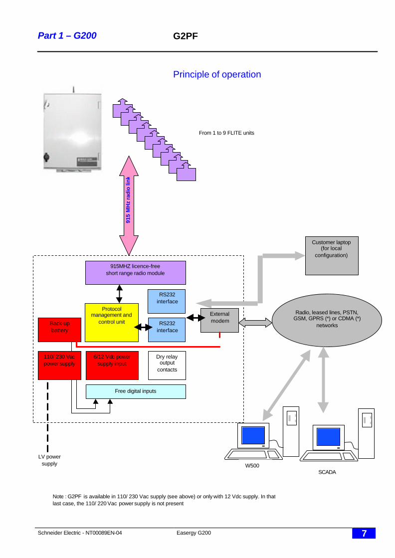
Principle of operation
915MHZ licence-freeshort range radio module
RS232interface
Protocolmanagement and
control unit
6/12 Vdc powersupply input
Customer laptop(for local
configuration)
From 1 to 9 FLITE units91
5 M
Hz
radi
o lin
k
Dry relayoutput
contacts
Free digital inputs
RS232interface
Back-upbattery
110/ 230 Vacpower supply
LV powersupply
Externalmodem
Radio, leased lines, PSTN,GSM, GPRS (*) or CDMA (*)
networks
SCADA
Note : G2PF is available in 110/ 230 Vac supply (see above) or only with 12 Vdc supply. In thatlast case, the 110/ 220 Vac power supply is not present
W500
Schneider Electric - NT00089EN-04 Easergy G200 8
Part 1 – G200 G2PF
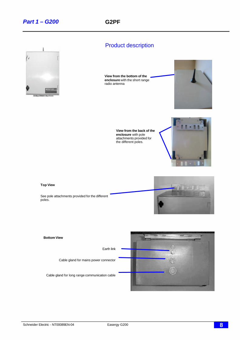
Product description
Top View
See pole attachments provided for the differentpoles.
View from the back of theenclosure with poleattachments provided forthe different poles.
View from the bottom of theenclosure with the short rangeradio antenna
Bottom View
Earth link
Cable gland for mains power connector
Cable gland for long range communication cable
Schneider Electric - NT00089EN-04 Easergy G200 9
Part 1 – G200 G2PF
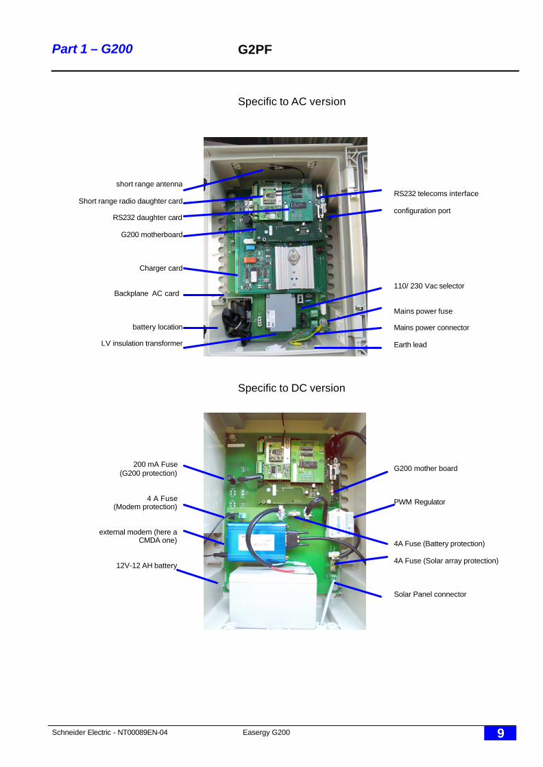
Specific to AC version
Specific to DC version
RS232 telecoms interface
configuration port
110/ 230 Vac selector
Mains power fuse
Mains power connector
Earth lead
short range antenna
Short range radio daughter card
RS232 daughter card
G200 motherboard
Charger card
Backplane AC card
battery location
LV insulation transformer
G200 mother board
PWM Regulator
4A Fuse (Battery protection)
4A Fuse (Solar array protection)
Solar Panel connector
200 mA Fuse(G200 protection)
4 A Fuse(Modem protection)
external modem (here aCMDA one)
12V-12 AH battery
Schneider Electric - NT00089EN-04 Easergy G200 10
Part 1 – G200 G2PF
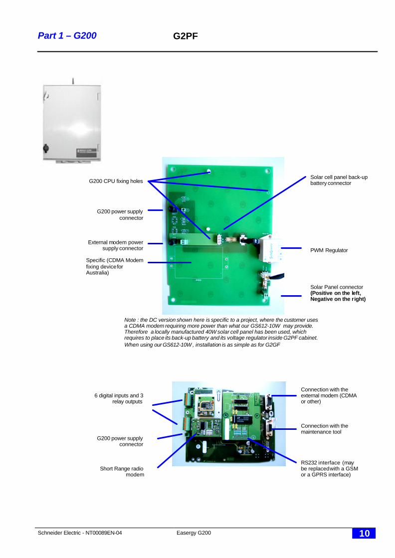
6 digital inputs and 3relay outputs
G200 power supplyconnector
Short Range radiomodem
Connection with theexternal modem (CDMAor other)
Connection with themaintenance tool
RS232 interface (maybe replaced with a GSMor a GPRS interface)
Note : the DC version shown here is specific to a project, where the customer usesa CDMA modem requiring more power than what our GS612-10W may provide.Therefore a locally manufactured 40W solar cell panel has been used, whichrequires to place its back-up battery and its voltage regulator inside G2PF cabinet.When using our GS612-10W , installation is as simple as for G2GF
Solar cell panel back-upbattery connector
PWM Regulator
Solar Panel connector(Positive on the left,Negative on the right)
G200 CPU fixing holes
G200 power supplyconnector
External modem powersupply connector
Specific (CDMA Modemfixing device forAustralia)
Schneider Electric - NT00089EN-04 Easergy G200 11
Part 1 – G200 G2PF
Electrical specifications
AC supply versionq LV supply characteristics§ 110 Vac (±10%), 60 Hz to 230 Vac (±10%), 50 Hz§ Overall power consumption: 80 VA max.§ LV input protected by HPC fuse - 2A rating - type gF -dimensions 10x38 mm.§ Screw connection.
q LV monitoring§ The absence of 110 Vac supply is detected when the voltage is lower than 80
Vac +/- 10V (or 160 Vac for 230 Vac).§ The power supply stops to supply the G200 unit if the LV supply absence
exceeds the battery backup time. Following a failure, the equipment powersupply is automatically restored when the LV supply returns.
§ The mechanical earth is connected to the 0V or the electrical ground of theassembly.
q DC supply§ Voltage between 10.8V and 14.8V.§ Protected by a 0.8 A semi time delayed fuse, located on the “Power Supply”
module.
q DC supply monitoring§ Monitoring of the 12 V generates the “charger fault” information when the voltage
is higher than 14.8 V ± 0.2V or lower than 11.2 V ± 0.1V.§ When the 12 V voltage drops below 10.8 V ± 0.1V for more than 5 minutes, the
general equipment power supply (12 V and 24 or 48 V) is interrupted in order toavoid total discharge of the batteries.
q Telecoms DC supply for external modems§ Voltage between 10.8V and 14.8V.§ Current available: 1A permanent.§ Protected by a 4 A time delayed fuse located on the right side of the rack:I max 6 A 8 A 11 A 16A 40 ATime limit 1 hour 2 mins 600 ms 150 ms 20 ms
q Telecom DC supply monitoring§ In the event of consumption in excess of 1.3 A ± 0.3 for more than 3 minutes, the
“telecommunication power supply” circuit is opened.
q Battery characteristics§ Lead battery, of the sealed type and requiring no maintenance.§ 12V / 7 Ah§ Charging time: 24 hours.§ Lifetime: greater than 3 years.§ Backup time: 8 hours without heating resistance§ Automatic failure of the equipment power supply in the event of total discharge.
q Battery monitoring§ Particular attention is paid to the battery; its availability is tested every 12 hours.§ An unsatisfactory battery test (insufficient capacity) increments a counter and a
satisfactory test decrements this counter.§ When this counter reaches 10, the “battery fault” message appears.§ This message warns the operator of the need for action (end of service life,
problems with charging, etc.).
Schneider Electric - NT00089EN-04 Easergy G200 12
Part 1 – G200 G2PF
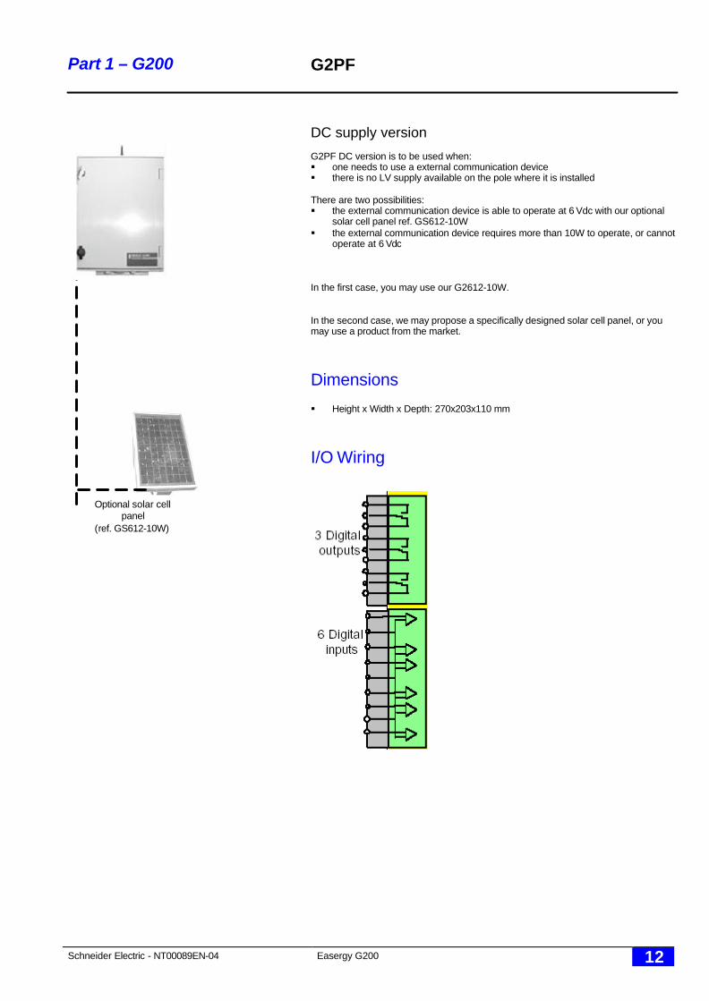
DC supply version
G2PF DC version is to be used when:§ one needs to use a external communication device§ there is no LV supply available on the pole where it is installed
There are two possibilities:§ the external communication device is able to operate at 6 Vdc with our optional
solar cell panel ref. GS612-10W§ the external communication device requires more than 10W to operate, or cannot
operate at 6 Vdc
In the first case, you may use our G2612-10W.
In the second case, we may propose a specifically designed solar cell panel, or youmay use a product from the market.
Dimensions
§ Height x Width x Depth: 270x203x110 mm
I/O Wiring
Optional solar cellpanel
(ref. GS612-10W)
Schneider Electric - NT00089EN-04 Easergy G200 13
Part 1 – G200 G2GF
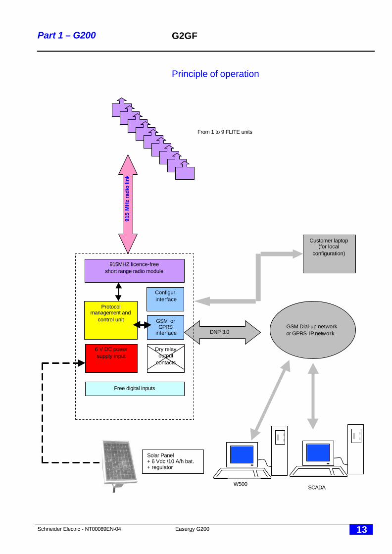
Principle of operation
915MHZ licence-freeshort range radio module
GSM orGPRS
interface
Protocolmanagement and
control unit
6 V DC powersupply input
DNP 3.0
Customer laptop(for local
configuration)
From 1 to 9 FLITE units91
5 M
Hz
radi
o lin
k
Dry relayoutput
contacts
Free digital inputs
Configur.interface
GSM Dial-up networkor GPRS IP network
SCADA
Solar Panel+ 6 Vdc /10 A/h bat.+ regulator
W500
Schneider Electric - NT00089EN-04 Easergy G200 14
Part 1 – G200 G2GF
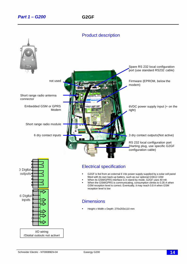
Product description
Electrical specification
§ G2GF is fed from an external 6 Vdc power supply supplied by a solar cell panelfitted with its own back-up battery, such as our optional GS612-10W
§ When its GSM/GPRS interface is in stand-by mode, G2GF uses 40 mA§ When the GSM/GPRS is communicating, consumption climbs to 0.35 A when
GSM reception level is correct. Eventually, it may reach 0.8 A when GSMreception level is low
Dimensions
§ Height x Width x Depth: 270x203x110 mm
Spare RS 232 local configurationport (use standard RS232 cable)
Firmware (EPROM, below themodem)
6VDC power supply input (+ on theright)
3 dry contact outputs(Not active)
RS 232 local configuration port(Harting plug, use specific G2GFconfiguration cable)
not used
Short range radio antennaconnector
Embedded GSM or GPRSModem
Short range radio module
6 dry contact inputs
I/O wiring(Digital outputs not active)
Schneider Electric - NT00089EN-04 Easergy G200 15
Part 1 – G200 G2SF
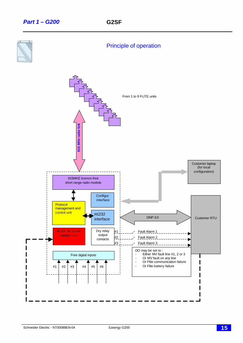
Principle of operation
915MHZ licence-freeshort range radio module
RS232interface
Protocolmanagement andcontrol unit
6/12V DC powersupply input
Customer RTUDNP 3.0
Customer laptop(for local
configuration)
From 1 to 9 FLITE units
915
MH
z ra
dio
link
Dry relayoutput
contacts
Free digital inputs
#1
#2
#3
#1 #2 #3 #4 #5 #6
Fault Alarm 1
Fault Alarm 2
Fault Alarm 3
Configur.interface
DO may be set to :- Either MV fault line #1, 2 or 3- Or MV fault on any line- Or Flite communication failure- Or Flite battery failure
Schneider Electric - NT00089EN-04 Easergy G200 16
Part 1 – G200 G2SF
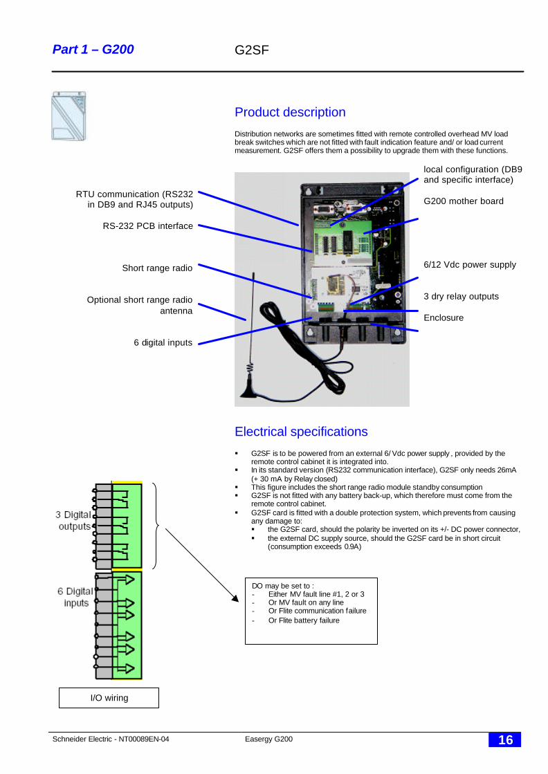
Product description
Distribution networks are sometimes fitted with remote controlled overhead MV loadbreak switches which are not fitted with fault indication feature and/ or load currentmeasurement. G2SF offers them a possibility to upgrade them with these functions.
Electrical specifications
§ G2SF is to be powered from an external 6/ Vdc power supply , provided by theremote control cabinet it is integrated into.
§ In its standard version (RS232 communication interface), G2SF only needs 26mA(+ 30 mA by Relay closed)
§ This figure includes the short range radio module standby consumption§ G2SF is not fitted with any battery back-up, which therefore must come from the
remote control cabinet.§ G2SF card is fitted with a double protection system, which prevents from causing
any damage to:§ the G2SF card, should the polarity be inverted on its +/- DC power connector,§ the external DC supply source, should the G2SF card be in short circuit
(consumption exceeds 0.9A)
local configuration (DB9and specific interface)
G200 mother board
6/12 Vdc power supply
3 dry relay outputs
Enclosure
RTU communication (RS232in DB9 and RJ45 outputs)
RS-232 PCB interface
Short range radio
Optional short range radioantenna
6 digital inputs
I/O wiring
DO may be set to :- Either MV fault line #1, 2 or 3- Or MV fault on any line- Or Flite communication failure- Or Flite battery failure
Schneider Electric - NT00089EN-04 Easergy G200 17
Part 1 – G200 G2SF
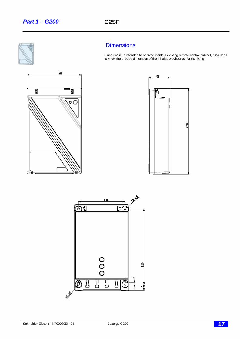
Dimensions
Since G2SF is intended to be fixed inside a existing remote control cabinet, it is usefulto know the precise dimension of the 4 holes provisioned for the fixing

Schneider Electric - NT00089EN-04 Easergy G200 18
Part 2 – FLITE
Part 2FLITE
Schneider Electric - NT00089EN-04 Easergy G200 19
Part 2 – FLITE Functions
Introduction
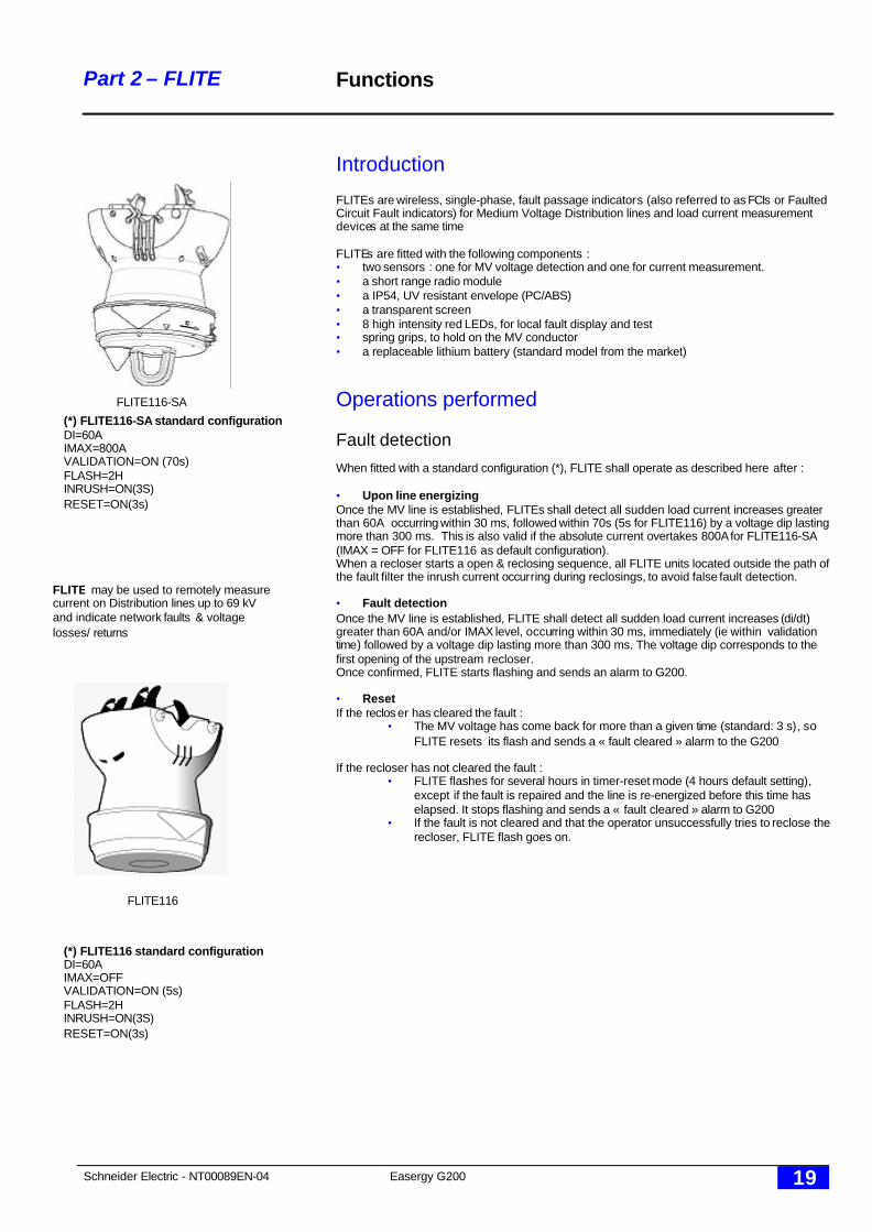
FLITEs are wireless, single-phase, fault passage indicators (also referred to as FCIs or FaultedCircuit Fault indicators) for Medium Voltage Distribution lines and load current measurementdevices at the same time
FLITEs are fitted with the following components :• two sensors : one for MV voltage detection and one for current measurement.• a short range radio module• a IP54, UV resistant envelope (PC/ABS)• a transparent screen• 8 high intensity red LEDs, for local fault display and test• spring grips, to hold on the MV conductor• a replaceable lithium battery (standard model from the market)
Operations performed
Fault detectionWhen fitted with a standard configuration (*), FLITE shall operate as described here after :
• Upon line energizingOnce the MV line is established, FLITEs shall detect all sudden load current increases greaterthan 60A occurring within 30 ms, followed within 70s (5s for FLITE116) by a voltage dip lastingmore than 300 ms. This is also valid if the absolute current overtakes 800A for FLITE116-SA(IMAX = OFF for FLITE116 as default configuration).When a recloser starts a open & reclosing sequence, all FLITE units located outside the path ofthe fault filter the inrush current occurring during reclosings, to avoid false fault detection.
• Fault detectionOnce the MV line is established, FLITE shall detect all sudden load current increases (di/dt)greater than 60A and/or IMAX level, occurring within 30 ms, immediately (ie within validationtime) followed by a voltage dip lasting more than 300 ms. The voltage dip corresponds to thefirst opening of the upstream recloser.Once confirmed, FLITE starts flashing and sends an alarm to G200.
• ResetIf the reclos er has cleared the fault :
• The MV voltage has come back for more than a given time (standard: 3 s), soFLITE resets its flash and sends a « fault cleared » alarm to the G200
If the recloser has not cleared the fault :• FLITE flashes for several hours in timer-reset mode (4 hours default setting),
except if the fault is repaired and the line is re-energized before this time haselapsed. It stops flashing and sends a « fault cleared » alarm to G200
• If the fault is not cleared and that the operator unsuccessfully tries to reclose therecloser, FLITE flash goes on.
FLITE may be used to remotely measurecurrent on Distribution lines up to 69 kVand indicate network faults & voltagelosses/ returns
FLITE116-SA
FLITE116
(*) FLITE116 standard configurationDI=60AIMAX=OFFVALIDATION=ON (5s)FLASH=2HINRUSH=ON(3S)RESET=ON(3s)
(*) FLITE116-SA standard configurationDI=60AIMAX=800AVALIDATION=ON (70s)FLASH=2HINRUSH=ON(3S)RESET=ON(3s)
Schneider Electric - NT00089EN-04 Easergy G200 20
Part 2 – FLITE Timing Diagram
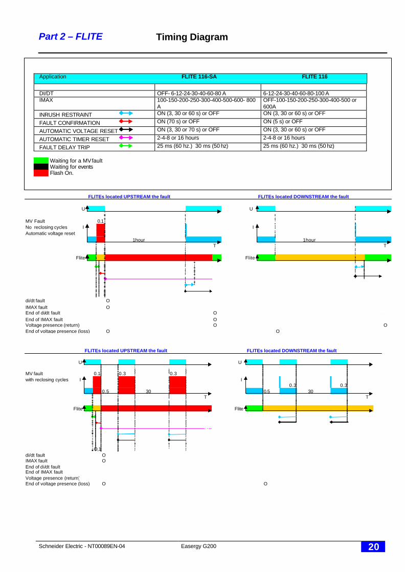
Application FLITE 116-SA FLITE 116
DI/DT OFF- 6-12-24-30-40-60-80 A 6-12-24-30-40-60-80-100 AIMAX 100-150-200-250-300-400-500-600- 800
AOFF-100-150-200-250-300-400-500 or600A
INRUSH RESTRAINT ON (3, 30 or 60 s) or OFF ON (3, 30 or 60 s) or OFF
FAULT CONFIRMATION ON (70 s) or OFF ON (5 s) or OFF
AUTOMATIC VOLTAGE RESET ON (3, 30 or 70 s) or OFF ON (3, 30 or 60 s) or OFF
AUTOMATIC TIMER RESET 2-4-8 or 16 hours 2-4-8 or 16 hours
FAULT DELAY TRIP 25 ms (60 hz.) 30 ms (50 hz) 25 ms (60 hz.) 30 ms (50 hz)
Waiting for a MV faultWaiting for eventsFlash On.
FLITEs located UPSTREAM the fault FLITEs located DOWNSTREAM the fault
U U
MV Fault 0.1No reclosing cycles I IAutomatic voltage reset
1hour 1hourT T
Flite Flite
di/dt fault OIMAX fault OEnd of di/dt fault OEnd of IMAX fault OVoltage presence (return) O OEnd of voltage presence (loss) O O
FLITEs located UPSTREAM the fault FLITEs located DOWNSTREAM the fault
U U
MV fault 0.1 0.3 0.3with reclosing cycles I I
0.3 0.30.5 30 0.5 30
T T
Flite Flite
O,1di/dt fault OIMAX fault OEnd of di/dt faultEnd of IMAX faultVoltage presence (return)End of voltage presence (loss) O O
Schneider Electric - NT00089EN-04 Easergy G200 21
Part 2 - FLITE Functions
Line monitoringIn parallel to the fault detection function, FLITE performs a load current measurement ( 3 to630 A ), a immediate voltage loss detection and a regular check of the MV voltage presence orabsence and the of its lithium battery voltage.
Each FLITE sends to the G200 unit, every end of period (a period = 1 hour), all the datacollected during that period :
I_MAX : maximum instantaneous current measuredI_MIN : minimum instantaneous current measuredI_MEAN : average current for the periodFLITE battery status
Upon SCADA request (for instance prior to switch loads), G200 ask all FLITEs to send theirinstantaneous current measurement (I_INST), so that the network operator can make sure thatloads may added to others.
By regularly downloading the I_MAX/I_MIN/ I_MEAN measurements from each FLITE, theSCADA operator has a clear view of the daily/ weekly/ yearly consumption on each phase oneach MV line of the network.
Load current measurement
The load current measurement is computed slightly differently on FLITE116 and FLITE116-SA:
• FLITE116:I_INST is a 30ms current measurement value sampled every 30s .Every 30s, FLITE116 compares its I_MAX and I_MEAN values and if I_INST is greater thanI_IMAX (or lower than I_MIN), it becomes the new I_MAX (or I_MIN) value. In addition, I_INSTis averaged with the present I_MEAN value so that to form the new I_MEAN value.
• FLITE116-SA:The principle remains the same with some improvements:I_INST is 3 s current measurement value sampled permanently.I_MAX and I_MIN are re-evaluated every 3sI_MEAN is the average of all I_INST values.
Lithium battery alarm
Each end of period, each G200 unit knows which FLITE unit is having lithium battery problem.Forwarded to the SCADA or the maintenance center, the operator knows he has to plan areplacement for that FLITE unit.This prevents to have non-working fault indicators on the network
Short range communication alarm
Although the short range communication G200-FLITES has been duly tested at time of on-siteinstallation, there may be new obstacles obstructing the direct line of sight needed for a goodcommunication (growing trees, parked trucks, new fences, etc.).This is why G200 is fitted with a special counter, which records all unsuccessfulcommunications to any FLITE : when a user-set limit is overtaken, an alarm is sent to theSCADA or maintenance center for action.
MV sag or absence (case of Flite 116-SA)
FLITE116-SA is permanently monitoring the medium voltage: as soon as a voltage dip occurs(even on single phase CB, recloser or fuse operation) a radio alarm is sent in real-time to theG200.Upon voltage return, a end of alarm is also sent to G200 but it is 70 s delayed to avoid multipleradio alarms during reclosing cycles.
MV sag or absence (case of Flite 116)
The MV status is sent to the G200 each hour with Flite 116 (not in real time).
Schneider Electric - NT00089EN-04 Easergy G200 22
Part 2 - FLITE Installation
Power supply
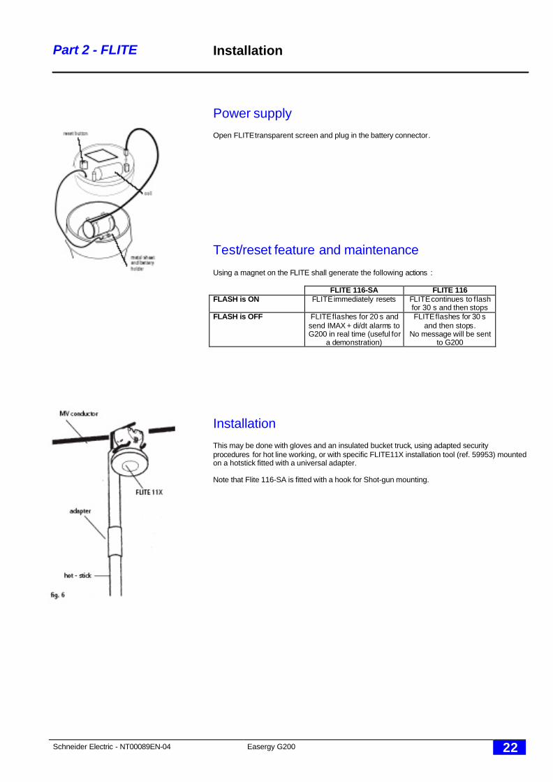
Open FLITE transparent screen and plug in the battery connector.
Test/reset feature and maintenance
Using a magnet on the FLITE shall generate the following actions :
FLITE 116-SA FLITE 116FLASH is ON FLITE immediately resets FLITE continues to f lash
for 30 s and then stopsFLASH is OFF FLITE flashes for 20 s and
send IMAX + di/dt alarms toG200 in real time (useful for
a demonstration)
FLITE flashes for 30 sand then stops.
No message will be sentto G200
Installation
This may be done with gloves and an insulated bucket truck, using adapted securityprocedures for hot line working, or with specific FLITE11X installation tool (ref. 59953) mountedon a hotstick fitted with a universal adapter.
Note that Flite 116-SA is fitted with a hook for Shot-gun mounting.
Schneider Electric - NT00089EN-04 Easergy G200 23
Part 2 - FLITE General specifications
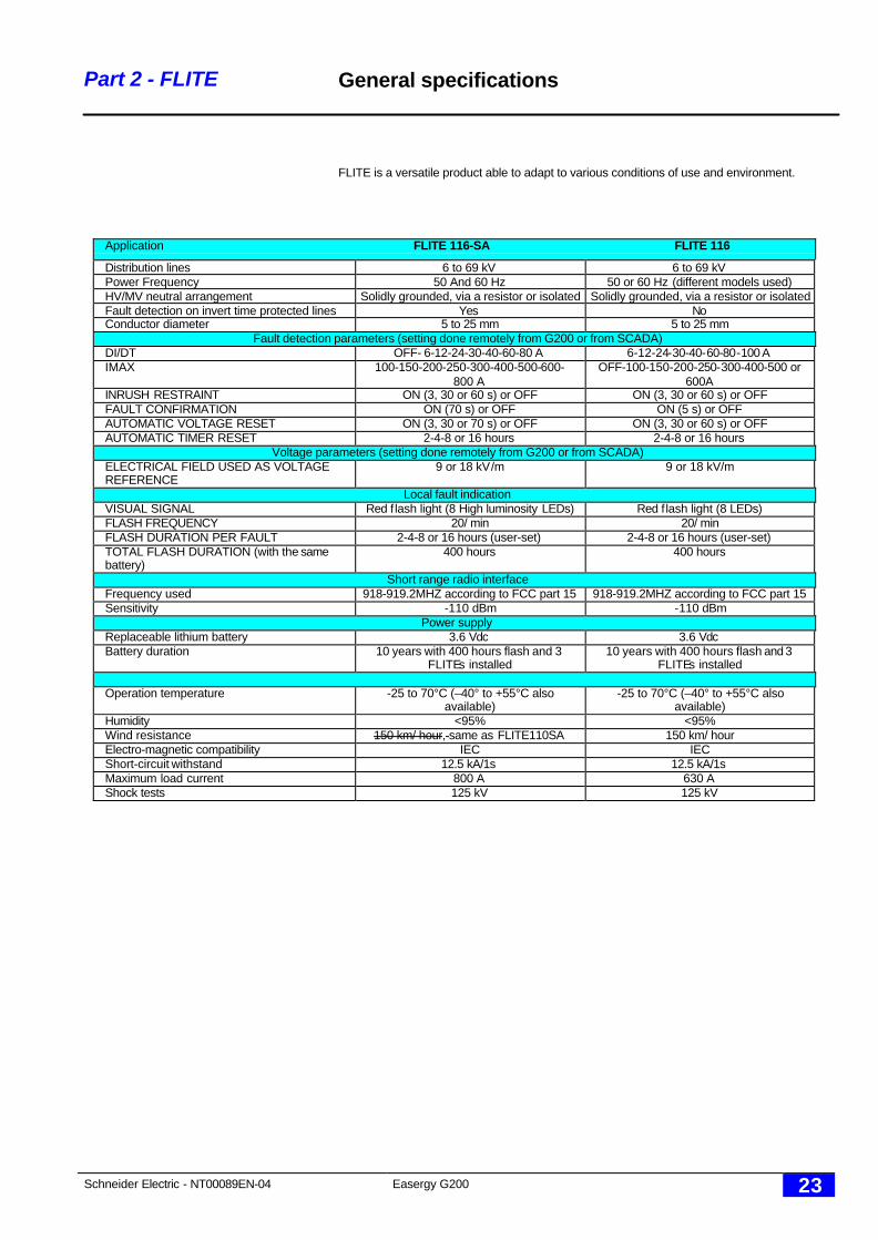
FLITE is a versatile product able to adapt to various conditions of use and environment.
Application FLITE 116-SA FLITE 116
Distribution lines 6 to 69 kV 6 to 69 kVPower Frequency 50 And 60 Hz 50 or 60 Hz (different models used)HV/MV neutral arrangement Solidly grounded, via a resistor or isolated Solidly grounded, via a resistor or isolatedFault detection on invert time protected lines Yes NoConductor diameter 5 to 25 mm 5 to 25 mm
Fault detection parameters (setting done remotely from G200 or from SCADA)DI/DT OFF- 6-12-24-30-40-60-80 A 6-12-24-30-40-60-80-100 AIMAX 100-150-200-250-300-400-500-600-
800 AOFF-100-150-200-250-300-400-500 or
600AINRUSH RESTRAINT ON (3, 30 or 60 s) or OFF ON (3, 30 or 60 s) or OFFFAULT CONFIRMATION ON (70 s) or OFF ON (5 s) or OFFAUTOMATIC VOLTAGE RESET ON (3, 30 or 70 s) or OFF ON (3, 30 or 60 s) or OFFAUTOMATIC TIMER RESET 2-4-8 or 16 hours 2-4-8 or 16 hours
Voltage parameters (setting done remotely from G200 or from SCADA)ELECTRICAL FIELD USED AS VOLTAGEREFERENCE
9 or 18 kV/m 9 or 18 kV/m
Local fault indicationVISUAL SIGNAL Red flash light (8 High luminosity LEDs) Red flash light (8 LEDs)FLASH FREQUENCY 20/ min 20/ minFLASH DURATION PER FAULT 2-4-8 or 16 hours (user-set) 2-4-8 or 16 hours (user-set)TOTAL FLASH DURATION (with the samebattery)
400 hours 400 hours
Short range radio interfaceFrequency used 918-919.2MHZ according to FCC part 15 918-919.2MHZ according to FCC part 15Sensitivity -110 dBm -110 dBm
Power supplyReplaceable lithium battery 3.6 Vdc 3.6 VdcBattery duration 10 years with 400 hours flash and 3
FLITEs installed10 years with 400 hours flash and 3
FLITEs installed
Operation temperature -25 to 70°C (–40° to +55°C alsoavailable)
-25 to 70°C (–40° to +55°C alsoavailable)
Humidity <95% <95%Wind resistance 150 km/ hour, same as FLITE110SA 150 km/ hourElectro-magnetic compatibility IEC IECShort-circuit withstand 12.5 kA/1s 12.5 kA/1sMaximum load current 800 A 630 AShock tests 125 kV 125 kV
Schneider Electric - NT00089EN-04 Easergy G200 24
Part 2 - FLITE Mechanical specifications
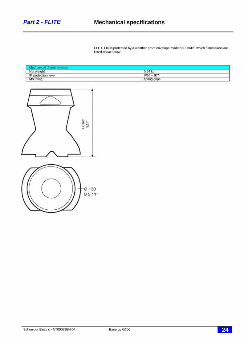
FLITE 116 is protected by a weather proof envelope made of PC/ABS which dimensions arelisted down below.
Mechanical characteristicsNet weight 0.54 kgIP protection level IP54 – IK7Mounting spring grips

Schneider Electric - NT00089EN-04 Easergy G200 25
Part 3 - installation
Part 3installation

Schneider Electric - NT00089EN-04 Easergy G200 26
Part 3 - Installation FLITE installation
q Introduction
When used in urban areas, many “natural” obstacles (vehicules, buildings, etc.) maydisturb the radio signal between a G200 and its FLITE units.
Diffraction, refraction or diffusion phenomenas can create areas of “shadows”,interrupting message receptions at points close to the sender while enabling a correctreception at a more distant point.
In addition, electromagnetic noises affect communication performance: FLITEinstallation close to a high power radio or cellular relay are to be avoided.
Below is are a list of rules to follow to ensure a reliable radio communication:
q Distanceü All FLITEs shall be placed within a 50 to 100 meters radius around the G200
(although depending on local conditions FLITE units may successfully operatewith no disturbance at even greater distances)
ü The maximum distance between FLITEs shall be 100 meters.
q G200 installationü Install G200 antenna above truck height, if pole is located along the road.ü Beware that noise is lower than –65 dBm on 902-928 MHz frequency range.
q G200 – FLITE orientation and positioning of antennasü Place FLITEs in the middle of the range rather than close to the pole.ü turn the G200 to the side of the FLITEs that are furthest awayü take care to distance G200 antenna from metallic objects on the pole.ü try to have a direct line of sight between G200 and all FLITEsü place the high power radio antenna (GSM, GPRS, CDMA or radio) of the G200
(pole mounted version) or of the RTU (card version) at least two meters from theG200 short range radio antenna.
Note : FLITEs are equipped with broad band antenna, so they may be placed at anypoint around the relay, as long as no metallic obstacle obstructs the link.
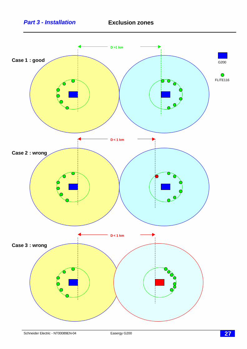
q Distances between FLITEs linked to two different G200 units (*)ü To avoid collisions, it is recommended to place two FLITEs linked to two
different G200 units by more than 1 km.ü Similarly, two G200 units must be separated by more than 1 km.
To check FLITEs positioning, use the RSSI command in the “Flite communicationparameters” (see description in FLITE COMMNICATION PARAMETERS).
(*): on a future G200 software release, it shall be possible to disminish this distance byselecting a different schedule for regular FLITES –to-G200 communications
G200
Radius =50 m
Radius =100 m
Unreliablecommunication area
F116
Normal cover area
Schneider Electric - NT00089EN-04 Easergy G200 27
Part 3 - Installation Exclusion zones
D >1 km
D < 1 km
D < 1 km
Case 1 : good
Case 2 : wrong
Case 3 : wrong
G200
FLITE116
Schneider Electric - NT00089EN-04 Easergy G200 28
Part 3 - Installation Radio or cellular antenna
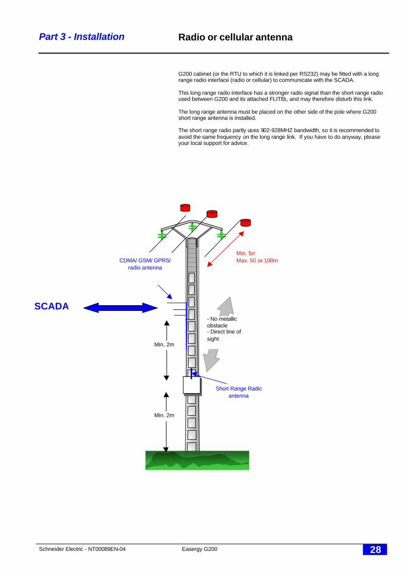
G200 cabinet (or the RTU to which it is linked per RS232) may be fitted with a longrange radio interface (radio or cellular) to communicate with the SCADA.
This long range radio interface has a stronger radio signal than the short range radioused between G200 and its attached FLITEs, and may therefore disturb this link.
The long range antenna must be placed on the other side of the pole where G200short range antenna is installed.
The short range radio partly uses 902-928MHZ bandwidth, so it is recommended toavoid the same frequency on the long range link. If you have to do anyway, pleaseyour local support for advice.
Min. 2m
Min. 2m
Min. 5mMax. 50 or 100m
- No metallicobstacle- Direct line ofsight
CDMA/ GSM/ GPRS/radio antenna
Short Range Radioantenna
SCADA
Schneider Electric - NT00089EN-04 Easergy G200 29
Part 3 – Installation SIM card for GSM/ GPRScommunications
Introduction to GSM/ GPRS networks
G200 units may communicate to the SCADA or W500 hoststhrough various medias, among which GSM (dial-up connections)or GPRS (IP address).
G200 offer includes embedded GSM/ GPRS interfaces as well asexternal GSM/ GPRS modem devices. To operate, theseinterfaces or devices need what is called a SIM card.
This SIM card is provided by your GSM/ GPRS network providerand contains the required information to hook the G200 unit ontothe GSM/ GPRS network.
To insert this card inside G200 embedded GSM/ GPRS interfacesor external GSM/ GPRS devices, process as explained here.
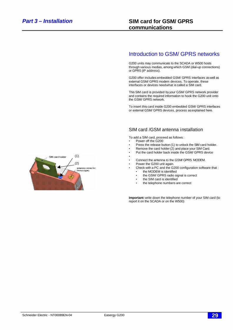
SIM card /GSM antenna installation
To add a SIM card, proceed as follows :• Power off the G200• Press the release button (1) to unlock the SIM card holder.• Remove the card holder (2) and place your SIM Card.• Put the card holder back inside the GSM/ GPRS device• • Connect the antenna to the GSM/ GPRS MODEM.• Power the G200 unit again.• Check with a PC and the G200 configuration software that :
• the MODEM is identified• the GSM/ GPRS radio signal is correct• the SIM card is identified• the telephone numbers are correct
Important: write down the telephone number of your SIM card (toreport it on the SCADA or on the W500)
(1)
(2)
Schneider Electric - NT00089EN-04 Easergy G200 30
Part 3 – Installation G200 mounting
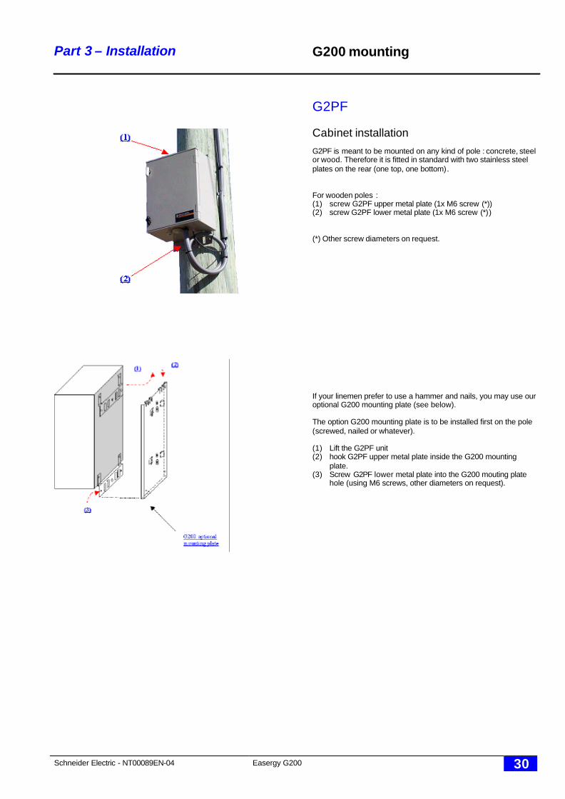
G2PF
Cabinet installationG2PF is meant to be mounted on any kind of pole : concrete, steelor wood. Therefore it is fitted in standard with two stainless steelplates on the rear (one top, one bottom).
For wooden poles :(1) screw G2PF upper metal plate (1x M6 screw (*))(2) screw G2PF lower metal plate (1x M6 screw (*))
(*) Other screw diameters on request.
If your linemen prefer to use a hammer and nails, you may use ouroptional G200 mounting plate (see below).
The option G200 mounting plate is to be installed first on the pole(screwed, nailed or whatever).
(1) Lift the G2PF unit(2) hook G2PF upper metal plate inside the G200 mounting
plate.(3) Screw G2PF lower metal plate into the G200 mouting plate
hole (using M6 screws, other diameters on request).
Schneider Electric - NT00089EN-04 Easergy G200 31
Part 3 - Installation G200 mounting
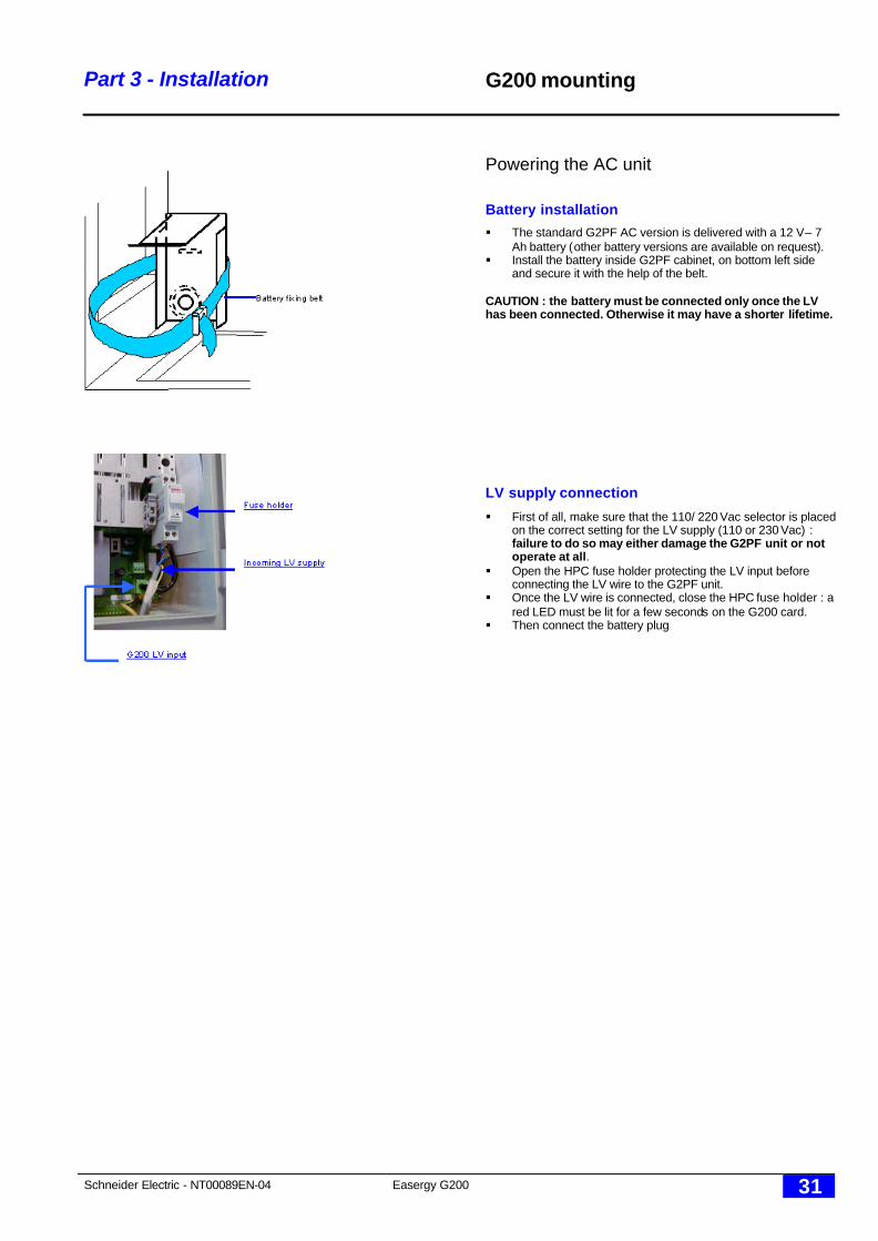
Powering the AC unit
Battery installation
§ The standard G2PF AC version is delivered with a 12 V – 7Ah battery (other battery versions are available on request).
§ Install the battery inside G2PF cabinet, on bottom left sideand secure it with the help of the belt.
CAUTION : the battery must be connected only once the LVhas been connected. Otherwise it may have a shorter lifetime.
LV supply connection
§ First of all, make sure that the 110/ 220 Vac selector is placedon the correct setting for the LV supply (110 or 230 Vac) :failure to do so may either damage the G2PF unit or notoperate at all.
§ Open the HPC fuse holder protecting the LV input beforeconnecting the LV wire to the G2PF unit.
§ Once the LV wire is connected, close the HPC fuse holder : ared LED must be lit for a few seconds on the G200 card.
§ Then connect the battery plug
Schneider Electric - NT00089EN-04 Easergy G200 32
Part 3 - Installation G200 mounting
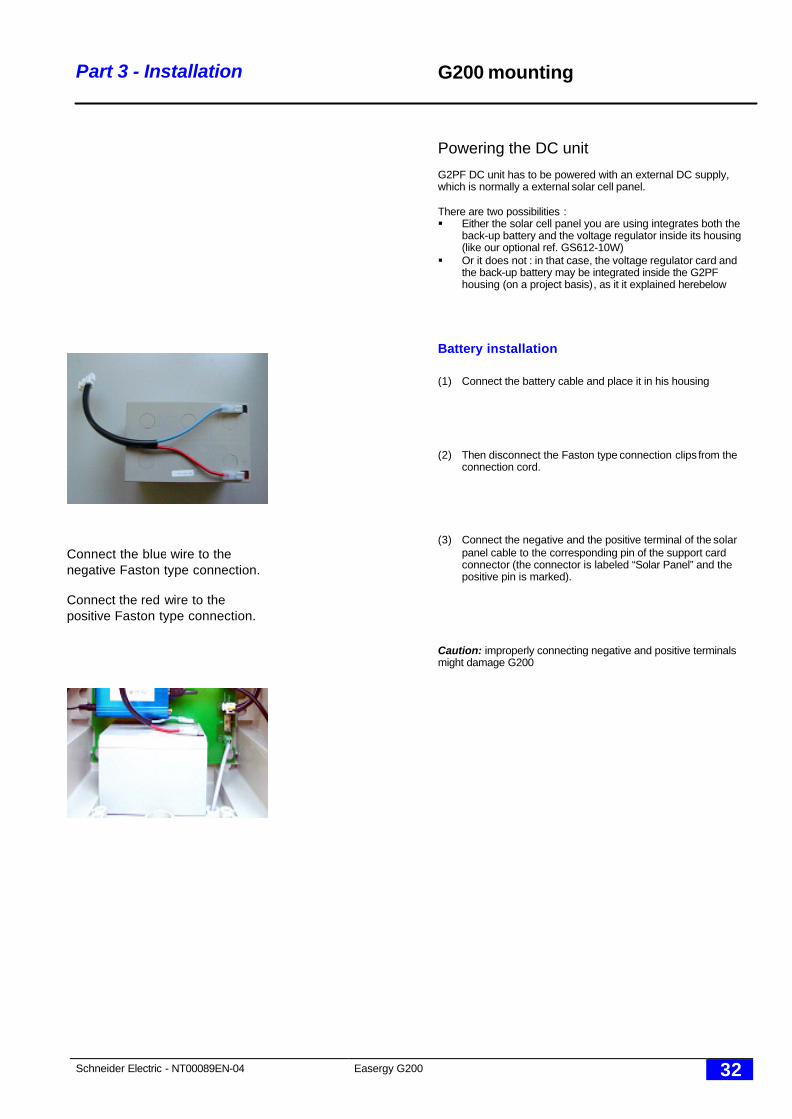
Powering the DC unit
G2PF DC unit has to be powered with an external DC supply,which is normally a external solar cell panel.
There are two possibilities :§ Either the solar cell panel you are using integrates both the
back-up battery and the voltage regulator inside its housing(like our optional ref. GS612-10W)
§ Or it does not : in that case, the voltage regulator card andthe back-up battery may be integrated inside the G2PFhousing (on a project basis), as it it explained herebelow
Battery installation
(1) Connect the battery cable and place it in his housing
(2) Then disconnect the Faston type connection clips from theconnection cord.
(3) Connect the negative and the positive terminal of the solarpanel cable to the corresponding pin of the support cardconnector (the connector is labeled “Solar Panel” and thepositive pin is marked).
Caution: improperly connecting negative and positive terminalsmight damage G200
Connect the blue wire to thenegative Faston type connection.
Connect the red wire to thepositive Faston type connection.
Schneider Electric - NT00089EN-04 Easergy G200 33
Part 3 - Installation G200 mounting
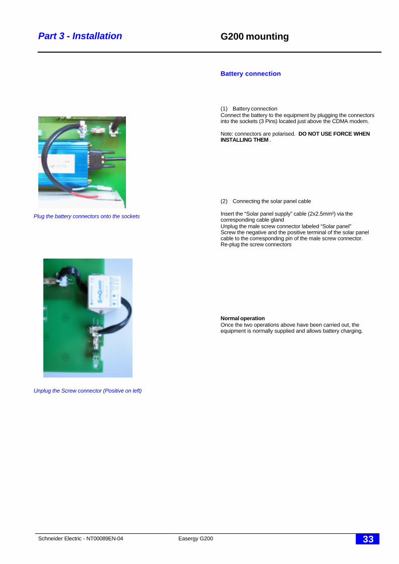
Battery connection
(1) Battery connectionConnect the battery to the equipment by plugging the connectorsinto the sockets (3 Pins) located just above the CDMA modem.
Note: connectors are polarised. DO NOT USE FORCE WHENINSTALLING THEM .
(2) Connecting the solar panel cable
Insert the “Solar panel supply” cable (2x2.5mm²) via thecorresponding cable glandUnplug the male screw connector labeled “Solar panel”Screw the negative and the positive terminal of the solar panelcable to the corresponding pin of the male screw connector.Re-plug the screw connectors
Normal operationOnce the two operations above have been carried out, theequipment is normally supplied and allows battery charging.
Unplug the Screw connector (Positive on left)
Plug the battery connectors onto the sockets

Schneider Electric - NT00089EN-04 Easergy G200 34
Part 3 - Installation G200 mounting
G2GF
§ G2GF is meant to be mounted on any kind of pole : concrete,steel or wood.
§ Since both power supply and battery back-up are locatedoutside the G2PF unit (inside the solar cell panel), there isnothing to do on this unit, except connecting the DC supply tothe G200 card and the GSM antenna to the GSM card.
Note : as a standard, solar cell panel ref. GS612-10W includes aGSM patch antenna. Therefore the antenna cable and the DCcable are located inside a single cable protection linking the G2GFunit to the GS612-10W unit.
Optional GS612-10WThis solar cell panel has been designed to fit the powerrequirement of G2GF units fitted with our embedded GSM (orGPRS) card.It is also possible to use it for the DC version of our G2PF, whenthe external modem used does not exceed the solar cell panelcapacity.
A separate « GS612-10W installation manual » documentexplains how to install it.
Schneider Electric - NT00089EN-04 Easergy G200 35
Part 3 - Installation G200 mounting
G2SF
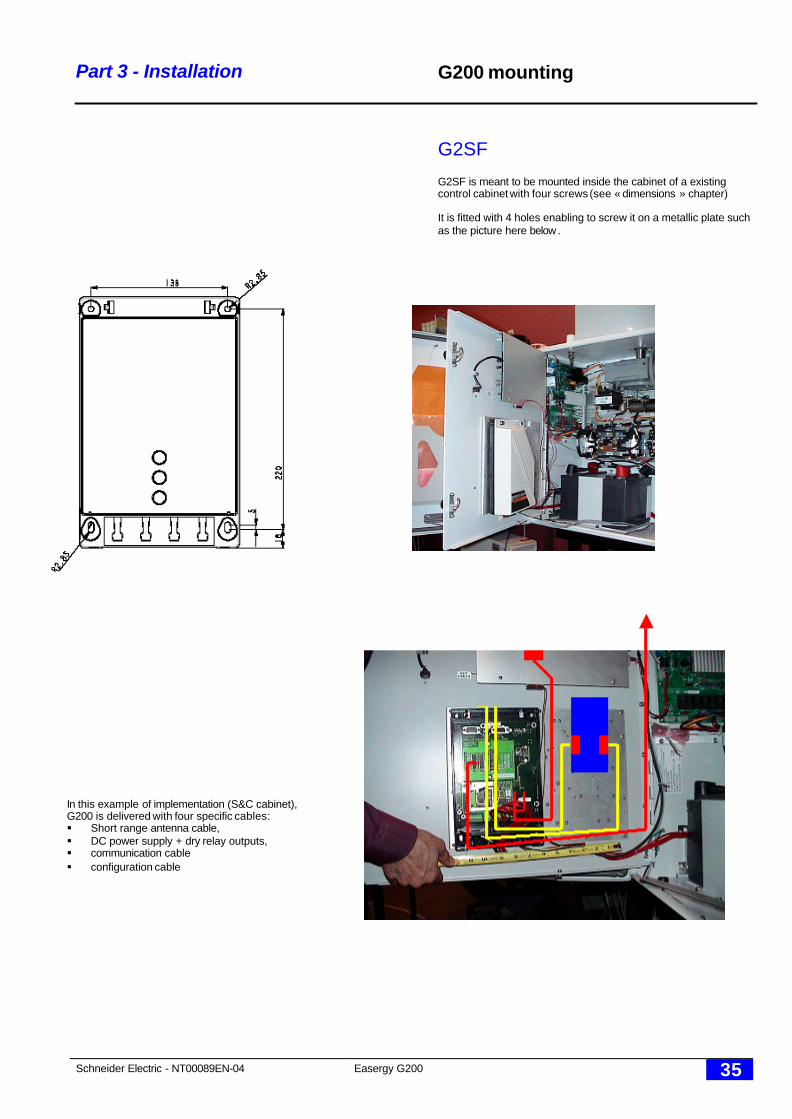
G2SF is meant to be mounted inside the cabinet of a existingcontrol cabinet with four screws (see « dimensions » chapter)
It is fitted with 4 holes enabling to screw it on a metallic plate suchas the picture here below .
In this example of implementation (S&C cabinet),G200 is delivered with four specific cables:§ Short range antenna cable,§ DC power supply + dry relay outputs,§ communication cable§ configuration cable

Schneider Electric - NT00089EN-04 Easergy G200 36
Part 4 - commissioning
Part 4Commissioning
Schneider Electric - NT00089EN-04 Easergy G200 37
Part 4 - Commissioning
ü
G200 configuration tools
Hardware required
The equipment is configured using a microcomputer operating under MS DOS, andaccessories provided:o "W 200 Configuration and diagnostics" software, included in the “Easergy W500”(Outils\UtilitairesW200\),o connection cable
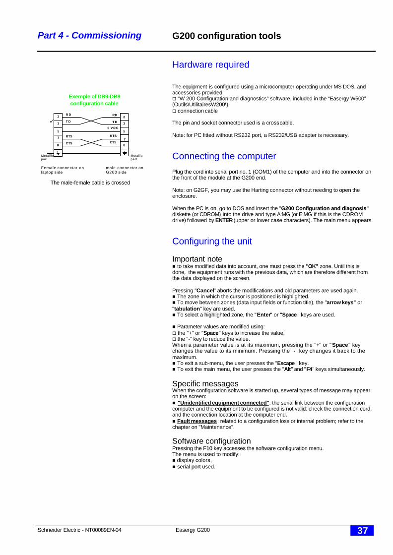
The pin and socket connector used is a cross cable.
Note: for PC fitted without RS232 port, a RS232/USB adapter is necessary.
Connecting the computer
Plug the cord into serial port no. 1 (COM1) of the computer and into the connector onthe front of the module at the G200 end.
Note: on G2GF, you may use the Harting connector without needing to open theenclosure.
When the PC is on, go to DOS and insert the "G200 Configuration and diagnosis "diskette (or CDROM) into the drive and type A:MG (or E:MG if this is the CDROMdrive) followed by ENTER (upper or lower case characters). The main menu appears.
Configuring the unit
Important noten to take modified data into account, one must press the "OK" zone. Until this isdone, the equipment runs with the previous data, which are therefore different fromthe data displayed on the screen.
Pressing "Cancel" aborts the modifications and old parameters are used again.n The zone in which the cursor is positioned is highlighted.n To move between zones (data input fields or function title), the "arrow keys" or"tabulation" key are used.n To select a highlighted zone, the "Enter" or "Space " keys are used.
n Parameter values are modified using:o the "+" or "Space" keys to increase the value,o the "-" key to reduce the value.When a parameter value is at its maximum, pressing the "+" or "Space" keychanges the value to its minimum. Pressing the "-" key changes it back to themaximum.n To exit a sub-menu, the user presses the "Escape " key.n To exit the main menu, the user presses the "Alt" and "F4" keys simultaneously.
Specific messagesWhen the configuration software is started up, several types of message may appearon the screen:n "Unidentified equipment connected": the serial link between the configurationcomputer and the equipment to be configured is not valid: check the connection cord,and the connection location at the computer end.n Fault messages: related to a configuration loss or internal problem; refer to thechapter on "Maintenance".
Software configurationPressing the F10 key accesses the software configuration menu.The menu is used to modify:n display colors,n serial port used.
Exemple of DB9-DB9configuration cable
Metallicpar t
RD
T D
RTS
CTS8
7
5
3
2
0 V D C
Metall icpart
T D
R D
CTS
RTS
3
2
5
8
7
Female connector on male connector onlaptop side G200 side
The male-female cable is crossed
Schneider Electric - NT00089EN-04 Easergy G200 38
Part 4 - Commissioning
"Equipment Name":§ Local name only used to access a hidden
menu (reserved for the manufacturer).
"Flite Identification":§ When selected, G200 searches for all
nearby FLITE units and records their uniquephysical address.
§ The process takes 2 minutes approx.
"Flite Communication parameters":§ Gives access to the short range radio G200-
FLITE communication parameters
"Parameters Flite x to y":§ Gives access to fault parameters of each
FLITE unit (referred to with a logical address1 to 9)
"RTU Address":§ Source address used by the remote SCADA
to identify this G200 through the DNP3protocol.
§ Adjustable from 0 to 65534..
"SCADA Address":§ Destination address used by the G200 to
identify the remote SCADA through the DNP3.0 protocol.
§ Adjustable from 0 to 65534..
For Hayes and GPRS version only:
This address is used when the following mode isconfigured in the communication parameters:
- SCADA- W500 + SCADA
"W500 Address":§ Destination address used by the G200 to
identify the remote W500 server through theDNP3 protocol (Destination).
§ Adjustable from 0 to 65534.
This address is used when the following mode isconfigured in the communication parameters:
- W500- W500 + SCADA
"Modem Slot 1":
§ Direct RS232: Direct RS232 : permanent link.
Radio external: radio link
§ MODEM HAYES (dial-up): Hayes : for Hayes compatible modems.
GSM: for AT commands compatible GSMmodems.
§ MODEM GPRSGPRS: for WAVECOM GPRS/ GSM modemswith embedded IP stack
“Communications Parameters”(DIRECTRS232 and DATA MODEM only):Gives access to long range communicationparameter settings
CPU configuration
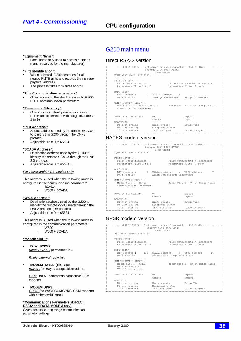
G200 main menu
Direct RS232 version+--------- MERLIN GERIN - Configuration and Diagnostic - ALT+F4=Exit ----------+¦ Easergy G200 DNP3 RS232 ¦¦ PROM vx.xx ¦¦ EQUIPMENT NAME: ???????? ¦¦ ¦¦ FLITE SETUP : ¦¦ Flite Identification Flite Communication Parameters ¦¦ Parameters Flite 1 to 6 Parameters Flite 7 to 9 ¦¦ ¦¦ DNP3 SETUP : ¦¦ RTU address : 0 SCADA address 0 ¦¦ DNP3 Profile Storage Parameters Relay Parameters ¦¦ ¦¦ COMMUNICATION SETUP : ¦¦ Modem Slot 1 : Direct RS 232 Modem Slot 2 : Short Range Radio ¦¦ Communication Parameters ¦¦ ¦¦ ¦¦ SAVE CONFIGURATION : OK Export ¦¦ Cancel Import ¦¦ DIAGNOSIS ¦¦ Display events Erase events Setup Time ¦¦ Display analog Equipment states ¦¦ Flite counters DNP3 analyser RADIO analyser ¦+------------------------------------------------------------------------------+
HAYES modem version+--------- MERLIN GERIN - Configuration and Diagnostic - ALT+F4=Exit ----------+¦ Easergy G200 DNP3 HAYES ¦¦ PROM vx.xx ¦¦ EQUIPMENT NAME: ???????? ¦¦ ¦¦ FLITE SETUP : ¦¦ Flite Identification Flite Communication Parameters ¦¦ Parameters Flite 1 to 6 Parameters Flite 7 to 9 ¦¦ ¦¦ DNP3 SETUP : ¦¦ RTU address : 0 SCADA address 0 W500 address : 0 ¦¦ DNP3 Profile Alarm and Storage Parameters ¦¦ ¦¦ COMMUNICATION SETUP : ¦¦ Modem Slot 1 : Hayes Modem Slot 2 : Short Range Radio ¦¦ Communication Parameters ¦¦ ¦¦ ¦¦ SAVE CONFIGURATION : OK Export ¦¦ Cancel Import ¦¦ DIAGNOSIS ¦¦ Display events Erase events Setup Time ¦¦ Display analog Equipment states ¦¦ Flite counters DNP3 analyser RADIO analyser ¦+------------------------------------------------------------------------------+
GPSR modem version+--------- MERLIN GERIN - Configuration and Diagnostic - ALT+F4=Exit ----------+¦ Easergy G200 DNP3 GPRS ¦¦ PROM vx.xx ¦¦ EQUIPMENT NAME: ???????? ¦¦ ¦¦ FLITE SETUP : ¦¦ Flite Identification Flite Communication Parameters ¦¦ Parameters Flite 1 to 6 Parameters Flite 7 to 9 ¦¦ ¦¦ DNP3 SETUP : ¦¦ RTU address : 112 SCADA address 4 W500 address : 16 ¦¦ DNP3 Profile Alarm and Storage Parameters ¦¦ ¦¦ COMMUNICATION SETUP : ¦¦ Modem Slot 1 : GPRS Modem Slot 2 : Short Range Radio ¦¦ GPRS Parameters ¦¦ TCP/IP parameters ¦¦ ¦¦ SAVE CONFIGURATION : OK Export ¦¦ Cancel Import ¦¦ DIAGNOSIS ¦¦ Display events Erase events Setup Time ¦¦ Display analog Equipment states ¦¦ Flite counters DNP3 analyser RADIO analyser ¦+------------------------------------------------------------------------------+
Schneider Electric - NT00089EN-04 Easergy G200 39
Part 4 – Commissioning
“GPRS Parameters”(GPRS MODEM only)§ Gives access to GPRS menu
“TCP/IP Parameters”(GPRS MODEM only):§ Gives access to TCP/ IP menu
“DNP3 Profile”:§ Gives access to the DNP3 protocol menu
“Alarm and storage parameters”:Gives access to alarms & storage menu
Note: for RS232, the link is permanent so alarmshave no use.
“Relay parameters”(Only for G2SF):§ menu used to configure Relay parameters.
n SAVE CONFIGURATION
§ " OK ": requested to confirm modificationsof any data, both in the main menu and inthe sub-menus.
§ "Cancel": all data that have been modifiedbut not yet confirmed are cancelled. Theequipment keeps the previous data, whichare displayed again on the screen.
§ "Export": the configuration are copied in afile with a “.cfg” extension:
All versionsFLITE.CFG: Flite parameters
Direct RS232:G2DRS232.cfg: G200 parameterscom.cfg: long range communication parameters
MODEM DATA (dial-up)G2DMOD.cfg: G200 parameterscom.cfg: long range communication parameters
MODEM GPRS:G2DGPRS.CFG: G200 parametersGPRS.cfg: G200 parametersIP.cfg: TCP/IP parameters
§ "Import": the configuration is imported from“.cfg file”. If no “.cfg” file is present, thedefault configuration is applied.
DIAGNOSISSee “part 5 - Maintenance” for more informationon these choices.
Time Setup is discussed below.
CPU configuration
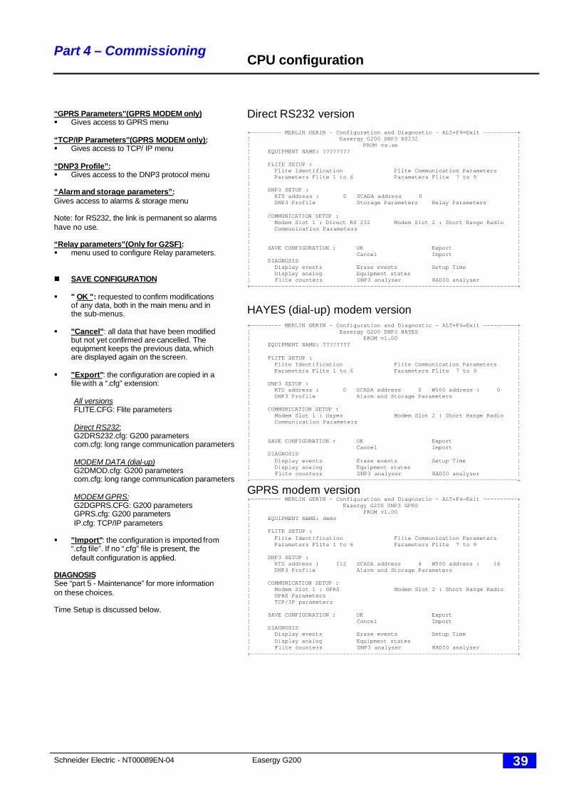
Direct RS232 version+--------- MERLIN GERIN - Configuration and Diagnostic - ALT+F4=Exit ----------+¦ Easergy G200 DNP3 RS232 ¦¦ PROM vx.xx ¦¦ EQUIPMENT NAME: ???????? ¦¦ ¦¦ FLITE SETUP : ¦¦ Flite Identification Flite Communication Parameters ¦¦ Parameters Flite 1 to 6 Parameters Flite 7 to 9 ¦¦ ¦¦ DNP3 SETUP : ¦¦ RTU address : 0 SCADA address 0 ¦¦ DNP3 Profile Storage Parameters Relay Parameters ¦¦ ¦¦ COMMUNICATION SETUP : ¦¦ Modem Slot 1 : Direct RS 232 Modem Slot 2 : Short Range Radio ¦¦ Communication Parameters ¦¦ ¦¦ ¦¦ SAVE CONFIGURATION : OK Export ¦¦ Cancel Import ¦¦ DIAGNOSIS ¦¦ Display events Erase events Setup Time ¦¦ Display analog Equipment states ¦¦ Flite counters DNP3 analyser RADIO analyser ¦+------------------------------------------------------------------------------+
HAYES (dial-up) modem version+--------- MERLIN GERIN - Configuration and Diagnostic - ALT+F4=Exit ----------+¦ Easergy G200 DNP3 HAYES ¦¦ PROM v1.00 ¦¦ EQUIPMENT NAME: ???????? ¦¦ ¦¦ FLITE SETUP : ¦¦ Flite Identification Flite Communication Parameters ¦¦ Parameters Flite 1 to 6 Parameters Flite 7 to 9 ¦¦ ¦¦ DNP3 SETUP : ¦¦ RTU address : 0 SCADA address 0 W500 address : 0 ¦¦ DNP3 Profile Alarm and Storage Parameters ¦¦ ¦¦ COMMUNICATION SETUP : ¦¦ Modem Slot 1 : Hayes Modem Slot 2 : Short Range Radio ¦¦ Communication Parameters ¦¦ ¦¦ ¦¦ SAVE CONFIGURATION : OK Export ¦¦ Cancel Import ¦¦ DIAGNOSIS ¦¦ Display events Erase events Setup Time ¦¦ Display analog Equipment states ¦¦ Flite counters DNP3 analyser RADIO analyser ¦+------------------------------------------------------------------------------+
GPRS modem version+--------- MERLIN GERIN - Configuration and Diagnostic - ALT+F4=Exit ----------+¦ Easergy G200 DNP3 GPRS ¦¦ PROM v1.00 ¦¦ EQUIPMENT NAME: demo ¦¦ ¦¦ FLITE SETUP : ¦¦ Flite Identification Flite Communication Parameters ¦¦ Parameters Flite 1 to 6 Parameters Flite 7 to 9 ¦¦ ¦¦ DNP3 SETUP : ¦¦ RTU address : 112 SCADA address 4 W500 address : 16 ¦¦ DNP3 Profile Alarm and Storage Parameters ¦¦ ¦¦ COMMUNICATION SETUP : ¦¦ Modem Slot 1 : GPRS Modem Slot 2 : Short Range Radio ¦¦ GPRS Parameters ¦¦ TCP/IP parameters ¦¦ ¦¦ SAVE CONFIGURATION : OK Export ¦¦ Cancel Import ¦¦ DIAGNOSIS ¦¦ Display events Erase events Setup Time ¦¦ Display analog Equipment states ¦¦ Flite counters DNP3 analyser RADIO analyser ¦+------------------------------------------------------------------------------+
Schneider Electric - NT00089EN-04 Easergy G200 40
Part 4 - Commissioning
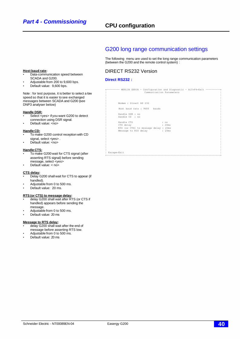
Host baud rate:• Data-communication speed between
SCADA and G200.• Adjustable from 200 to 9,600 bps.• Default value: 9,600 bps.
Note : for test purpose, it is better to select a lowspeed so that it is easier to see exchangedmessages between SCADA and G200 (seeDNP3 analyser below)
Handle DSR:• Select <yes> if you want G200 to detect
connection using DSR signal.• Default value: <no>
Handle CD:• To make G200 control reception with CD
signal, select <yes> .• Default value: <no>
Handle CTS:• To make G200 wait for CTS signal (after
asserting RTS signal) before sendingmessage, select <yes>
• Default value: < no>
CTS delay:• Delay G200 shall wait for CTS to appear (if
handled).• Adjustable from 0 to 500 ms.• Default value: 20 ms.
RTS (or CTS) to message delay:• delay G200 shall wait after RTS (or CTS if
handled) appears before sending themessage.
• Adjustable from 0 to 500 ms.• Default value: 20 ms
Message to RTS delay:• delay G200 shall wait after the end of
message before asserting RTS low.• Adjustable from 0 to 500 ms.• Default value: 20 ms
CPU configuration
G200 long range communication settings
The following menu are used to set the long range communication parameters(between the G200 and the remote control system) :
DIRECT RS232 Version
Direct RS232 :
+--------- MERLIN GERIN - Configuration and Diagnostic - ALT+F4=Exit ----------+¦ Communication Parameters ¦¦ ¦¦ ¦¦ ¦¦ Modem : Direct RS 232 ¦¦ ¦¦ Host baud rate : 9600 bauds ¦¦ ¦¦ Handle DSR : no ¦¦ Handle CD : no ¦¦ ¦¦ Handle CTS : no ¦¦ CTS delay : 20ms ¦¦ RTS (or CTS) to message delay : 20ms ¦¦ Message to RTS delay : 20ms ¦¦ ¦¦ ¦¦ ¦¦ ¦¦ ¦¦ ¦¦ ¦¦ Escape=Exit ¦+------------------------------------------------------------------------------+
Schneider Electric - NT00089EN-04 Easergy G200 41
Part 4 - Commissioning
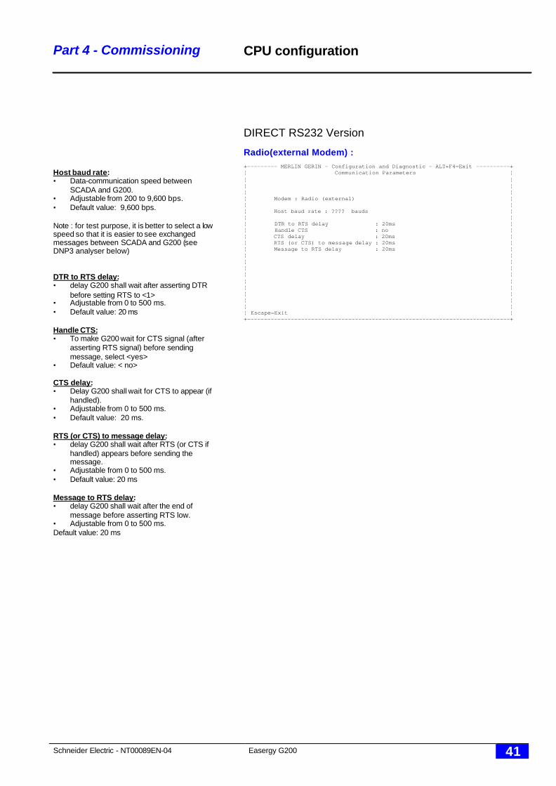
Host baud rate:• Data-communication speed between
SCADA and G200.• Adjustable from 200 to 9,600 bps.• Default value: 9,600 bps.
Note : for test purpose, it is better to select a lowspeed so that it is easier to see exchangedmessages between SCADA and G200 (seeDNP3 analyser below)
DTR to RTS delay:• delay G200 shall wait after asserting DTR
before setting RTS to <1>• Adjustable from 0 to 500 ms.• Default value: 20 ms
Handle CTS:• To make G200 wait for CTS signal (after
asserting RTS signal) before sendingmessage, select <yes>
• Default value: < no>
CTS delay:• Delay G200 shall wait for CTS to appear (if
handled).• Adjustable from 0 to 500 ms.• Default value: 20 ms.
RTS (or CTS) to message delay:• delay G200 shall wait after RTS (or CTS if
handled) appears before sending themessage.
• Adjustable from 0 to 500 ms.• Default value: 20 ms
Message to RTS delay:• delay G200 shall wait after the end of
message before asserting RTS low.• Adjustable from 0 to 500 ms.Default value: 20 ms
CPU configuration
DIRECT RS232 Version
Radio(external Modem) :+--------- MERLIN GERIN - Configuration and Diagnostic - ALT+F4=Exit ----------+¦ Communication Parameters ¦¦ ¦¦ ¦¦ ¦¦ Modem : Radio (external) ¦¦ ¦¦ Host baud rate : ???? bauds ¦¦ ¦¦ DTR to RTS delay : 20ms ¦¦ Handle CTS : no ¦¦ CTS delay : 20ms ¦¦ RTS (or CTS) to message delay : 20ms ¦¦ Message to RTS delay : 20ms ¦¦ ¦¦ ¦¦ ¦¦ ¦¦ ¦¦ ¦¦ ¦¦ ¦¦ ¦¦ Escape=Exit ¦+------------------------------------------------------------------------------+
Schneider Electric - NT00089EN-04 Easergy G200 42
Part 4 - Commissioning
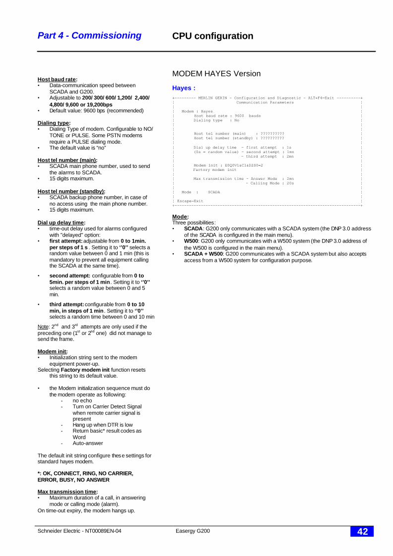
Host baud rate:• Data-communication speed between
SCADA and G200.• Adjustable to 200/ 300/ 600/ 1,200/ 2,400/
4,800/ 9,600 or 19,200bps• Default value: 9600 bps (recommended)
Dialing type:• Dialing Type of modem. Configurable to NO/
TONE or PULSE. Some PSTN modemsrequire a PULSE dialing mode.
• The default value is “no”
Host tel number (main):• SCADA main phone number, used to send
the alarms to SCADA.• 15 digits maximum.
Host tel number (standby):• SCADA backup phone number, in case of
no access using the main phone number.• 15 digits maximum.
Dial up delay time:• time-out delay used for alarms configured
with "delayed" option:• first attempt: adjustable from 0 to 1min.
per steps of 1 s . Setting it to ‘’0’’ selects arandom value between 0 and 1 min (this ismandatory to prevent all equipment callingthe SCADA at the same time).
• second attempt: configurable from 0 to5min. per steps of 1 min . Setting it to ‘’0’’selects a random value between 0 and 5min.
• third attempt: configurable from 0 to 10min, in steps of 1 min . Setting it to ‘’0’’selects a random time between 0 and 10 min
Note: 2nd and 3rd attempts are only used if thepreceding one (1st or 2nd one) did not manage tosend the frame.
Modem init:• Initialization string sent to the modem
equipment power-up.Selecting Factory modem init function resets
this string to its default value.
• the Modem initialization sequence must dothe modem operate as following:
- no echo- Turn on Carrier Detect Signal
when remote carrier signal ispresent
- Hang up when DTR is low- Return basic* result codes as
Word- Auto-answer
The default init string configure these settings forstandard hayes modem.
*: OK, CONNECT, RING, NO CARRIER,ERROR, BUSY, NO ANSWER
Max transmission time:• Maximum duration of a call, in answering
mode or calling mode (alarm).On time-out expiry, the modem hangs up.
CPU configuration
MODEM HAYES Version
Hayes :+--------- MERLIN GERIN - Configuration and Diagnostic - ALT+F4=Exit ----------+¦ Communication Parameters ¦¦ ¦¦ Modem : Hayes ¦¦ Host baud rate : 9600 bauds ¦¦ Dialing type : No ¦¦ ¦¦ ¦¦ Host tel number (main) : ?????????? ¦¦ Host tel number (standby) : ?????????? ¦¦ ¦¦ Dial up delay time - first attempt : 1s ¦¦ (0s = random value) - second attempt : 1mn ¦¦ - third attempt : 2mn ¦¦ ¦¦ Modem init : E0Q0V1&C1&D2S0=2 ¦¦ Factory modem init ¦¦ ¦¦ Max transmission time - Answer Mode : 2mn ¦¦ - Calling Mode : 20s ¦¦ ¦¦ Mode : SCADA ¦¦ ¦¦ Escape=Exit ¦+------------------------------------------------------------------------------+
Mode:Three possibilities:• SCADA: G200 only communicates with a SCADA system (the DNP 3.0 address
of the SCADA is configured in the main menu).• W500: G200 only communicates with a W500 system (the DNP 3.0 address of
the W500 is configured in the main menu).• SCADA + W500: G200 communicates with a SCADA system but also accepts
access from a W500 system for configuration purpose.
Schneider Electric - NT00089EN-04 Easergy G200 43
Part 4 - Commissioning
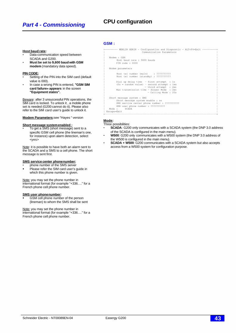
Host baud rate:• Data-communication speed between
SCADA and G200.• Must be set to 9,600 baud with GSM
modem (mandatory data speed).
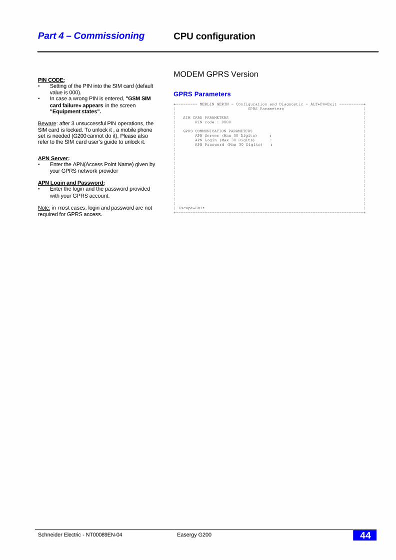
PIN CODE:• Setting of the PIN into the SIM card (default
value is 000).• In case a wrong PIN is entered, "GSM SIM
card failure» appears in the screen"Equipment states".
Beware: after 3 unsuccessful PIN operations, theSIM card is locked. To unlock it , a mobile phoneset is needed (G200 cannot do it). Please alsorefer to the SIM card user’s guide to unlock it.
Modem Parameters: see “Hayes “ version
Short message system enabled :• To get a SMS (short message) sent to a
specific GSM cell phone (the lineman’s one,for instance) upon alarm detection, select<yes>
Note: it is possible to have both an alarm sent tothe SCADA and a SMS to a cell phone. The shortmessage is sent first.
SMS service center phone number:• phone number of the SMS server§ Please refer the SIM card user’s guide in
which this phone number is given.
Note: you may set the phone number ininternational format (for example “+336….” for aFrench phone cell phone number.
SMS user phone number:§ GSM cell phone number of the person
(lineman) to whom the SMS shall be sent
Note: you may set the phone number ininternational format (for example “+336….” for aFrench phone cell phone number.
CPU configuration
GSM :+--------- MERLIN GERIN - Configuration and Diagnostic - ALT+F4=Exit ----------+¦ Communication Parameters ¦¦ ¦¦ Modem : GSM ¦¦ Host baud rate : 9600 bauds ¦¦ PIN code : 0000 ¦¦ ¦¦ Modem parameters ¦¦ ¦¦ Host tel number (main) : ?????????? ¦¦ Host tel number (standby) : ?????????? ¦¦ ¦¦ Dial up delay time - first attempt : 1s ¦¦ (0s = random value) - second attempt : 1mn ¦¦ - third attempt : 2mn ¦¦ Max transmission time - Answer Mode : 2mn ¦¦ - Calling Mode : 20s ¦¦ ¦¦ Short message system : SMS ¦¦ Short message system enable : no ¦¦ SMS service center phone number : ?????????? ¦¦ SMS user phone number : ?????????? ¦¦ Mode : SCADA ¦¦ Escape=Exit ¦+------------------------------------------------------------------------------+
Mode:Three possibilities:• SCADA: G200 only communicates with a SCADA system (the DNP 3.0 address
of the SCADA is configured in the main menu).• W500: G200 only communicates with a W500 system (the DNP 3.0 address of
the W500 is configured in the main menu).• SCADA + W500: G200 communicates with a SCADA system but also accepts
access from a W500 system for configuration purpose.
Schneider Electric - NT00089EN-04 Easergy G200 44
Part 4 – Commissioning
PIN CODE:• Setting of the PIN into the SIM card (default
value is 000).• In case a wrong PIN is entered, "GSM SIM
card failure» appears in the screen"Equipment states".
Beware: after 3 unsuccessful PIN operations, theSIM card is locked. To unlock it , a mobile phoneset is needed (G200 cannot do it). Please alsorefer to the SIM card user’s guide to unlock it.
APN Server:• Enter the APN(Access Point Name) given by
your GPRS network provider
APN Login and Password:• Enter the login and the password provided
with your GPRS account.
Note: in most cases, login and password are notrequired for GPRS access.
CPU configuration
MODEM GPRS Version
GPRS Parameters+--------- MERLIN GERIN - Configuration and Diagnostic - ALT+F4=Exit ----------+¦ GPRS Parameters ¦¦ ¦¦ SIM CARD PARAMETERS ¦¦ PIN code : 0000 ¦¦ ¦¦ GPRS COMMUNICATION PARAMETERS ¦¦ APN Server (Max 30 Digits) : ¦¦ APN Login (Max 30 Digits) : ¦¦ APN Password (Max 30 Digits) : ¦¦ ¦¦ ¦¦ ¦¦ ¦¦ ¦¦ ¦¦ ¦¦ ¦¦ ¦¦ ¦¦ ¦¦ ¦¦ ¦¦ Escape=Exit ¦+------------------------------------------------------------------------------+
Schneider Electric - NT00089EN-04 Easergy G200 45
Part 4 – Commissioning
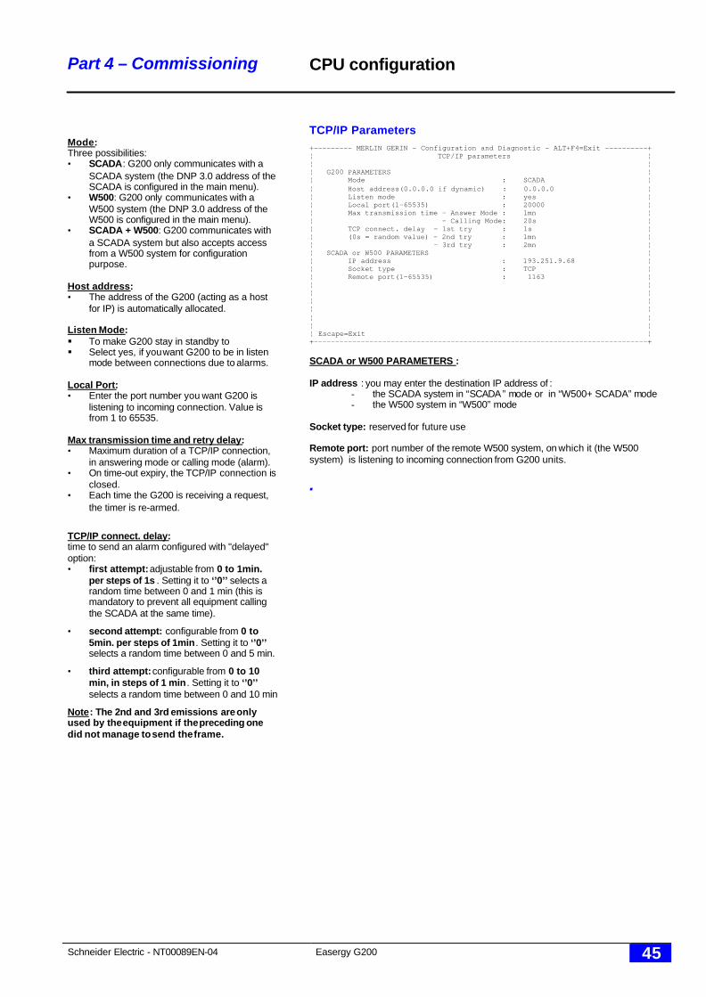
Mode:Three possibilities:• SCADA: G200 only communicates with a
SCADA system (the DNP 3.0 address of theSCADA is configured in the main menu).
• W500: G200 only communicates with aW500 system (the DNP 3.0 address of theW500 is configured in the main menu).
• SCADA + W500: G200 communicates witha SCADA system but also accepts accessfrom a W500 system for configurationpurpose.
Host address:• The address of the G200 (acting as a host
for IP) is automatically allocated.
Listen Mode:§ To make G200 stay in standby to§ Select yes, if you want G200 to be in listen
mode between connections due to alarms.
Local Port:• Enter the port number you want G200 is
listening to incoming connection. Value isfrom 1 to 65535.
Max transmission time and retry delay:• Maximum duration of a TCP/IP connection,
in answering mode or calling mode (alarm).• On time-out expiry, the TCP/IP connection is
closed.• Each time the G200 is receiving a request,
the timer is re-armed.
TCP/IP connect. delay:time to send an alarm configured with "delayed"option:• first attempt: adjustable from 0 to 1min.
per steps of 1s . Setting it to ‘’0’’ selects arandom time between 0 and 1 min (this ismandatory to prevent all equipment callingthe SCADA at the same time).
• second attempt: configurable from 0 to5min. per steps of 1min. Setting it to ‘’0’’selects a random time between 0 and 5 min.
• third attempt: configurable from 0 to 10min, in steps of 1 min . Setting it to ‘’0’’selects a random time between 0 and 10 min
Note: The 2nd and 3rd emissions are onlyused by the equipment if the preceding onedid not manage to send the frame.
CPU configuration
TCP/IP Parameters+--------- MERLIN GERIN - Configuration and Diagnostic - ALT+F4=Exit ----------+¦ TCP/IP parameters ¦¦ ¦¦ G200 PARAMETERS ¦¦ Mode : SCADA ¦¦ Host address(0.0.0.0 if dynamic) : 0.0.0.0 ¦¦ Listen mode : yes ¦¦ Local port(1-65535) : 20000 ¦¦ Max transmission time - Answer Mode : 1mn ¦¦ - Calling Mode: 20s ¦¦ TCP connect. delay - 1st try : 1s ¦¦ (0s = random value) - 2nd try : 1mn ¦¦ - 3rd try : 2mn ¦¦ SCADA or W500 PARAMETERS ¦¦ IP address : 193.251.9.68 ¦¦ Socket type : TCP ¦¦ Remote port(1-65535) : 1163 ¦¦ ¦¦ ¦¦ ¦¦ ¦¦ ¦¦ ¦¦ Escape=Exit ¦+------------------------------------------------------------------------------+
SCADA or W500 PARAMETERS :
IP address : you may enter the destination IP address of :- the SCADA system in “SCADA” mode or in “W500+ SCADA” mode- the W500 system in “W500” mode
Socket type: reserved for future use
Remote port: port number of the remote W500 system, on which it (the W500system) is listening to incoming connection from G200 units.
.
Schneider Electric - NT00089EN-04 Easergy G200 46
Part 4 – Commissioning
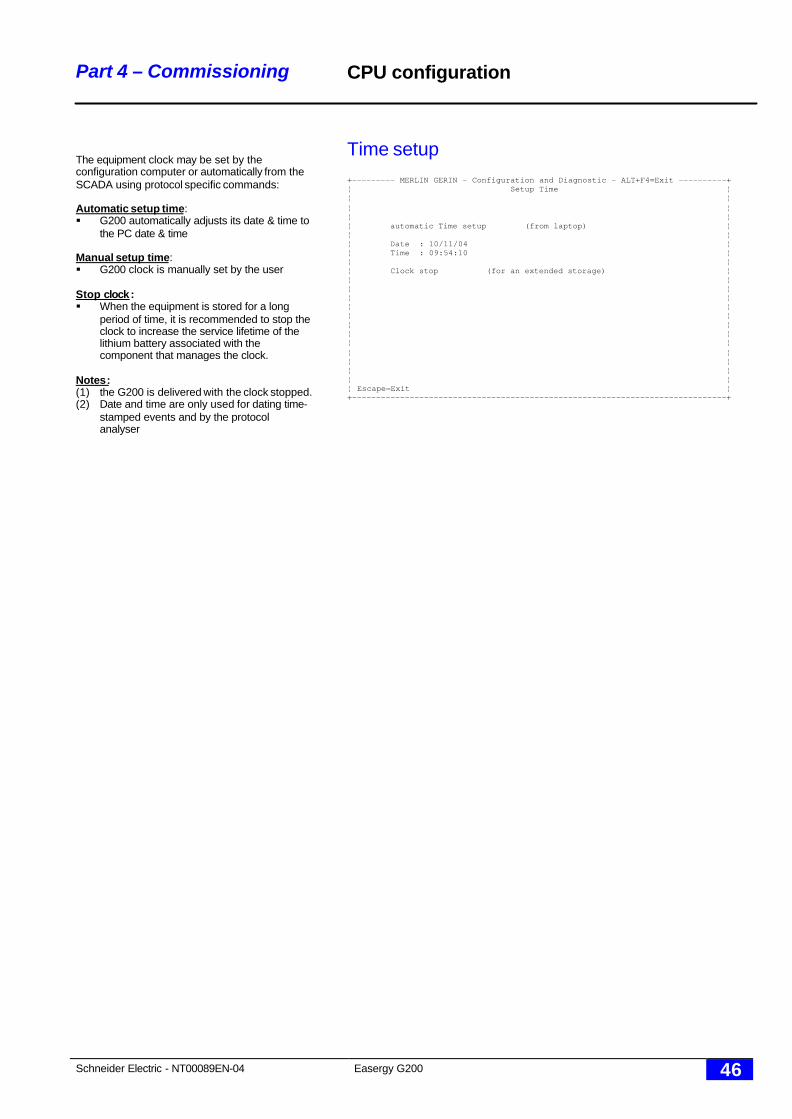
The equipment clock may be set by theconfiguration computer or automatically from theSCADA using protocol specific commands:
Automatic setup time:§ G200 automatically adjusts its date & time to
the PC date & time
Manual setup time:§ G200 clock is manually set by the user
Stop clock:§ When the equipment is stored for a long
period of time, it is recommended to stop theclock to increase the service lifetime of thelithium battery associated with thecomponent that manages the clock.
Notes:(1) the G200 is delivered with the clock stopped.(2) Date and time are only used for dating time-
stamped events and by the protocolanalyser
CPU configuration
Time setup+--------- MERLIN GERIN - Configuration and Diagnostic - ALT+F4=Exit ----------+¦ Setup Time ¦¦ ¦¦ ¦¦ ¦¦ automatic Time setup (from laptop) ¦¦ ¦¦ Date : 10/11/04 ¦¦ Time : 09:54:10 ¦¦ ¦¦ Clock stop (for an extended storage) ¦¦ ¦¦ ¦¦ ¦¦ ¦¦ ¦¦ ¦¦ ¦¦ ¦¦ ¦¦ ¦¦ ¦¦ ¦¦ Escape=Exit ¦+------------------------------------------------------------------------------+
Schneider Electric - NT00089EN-04 Easergy G200 47
Part 4 – Commissioning
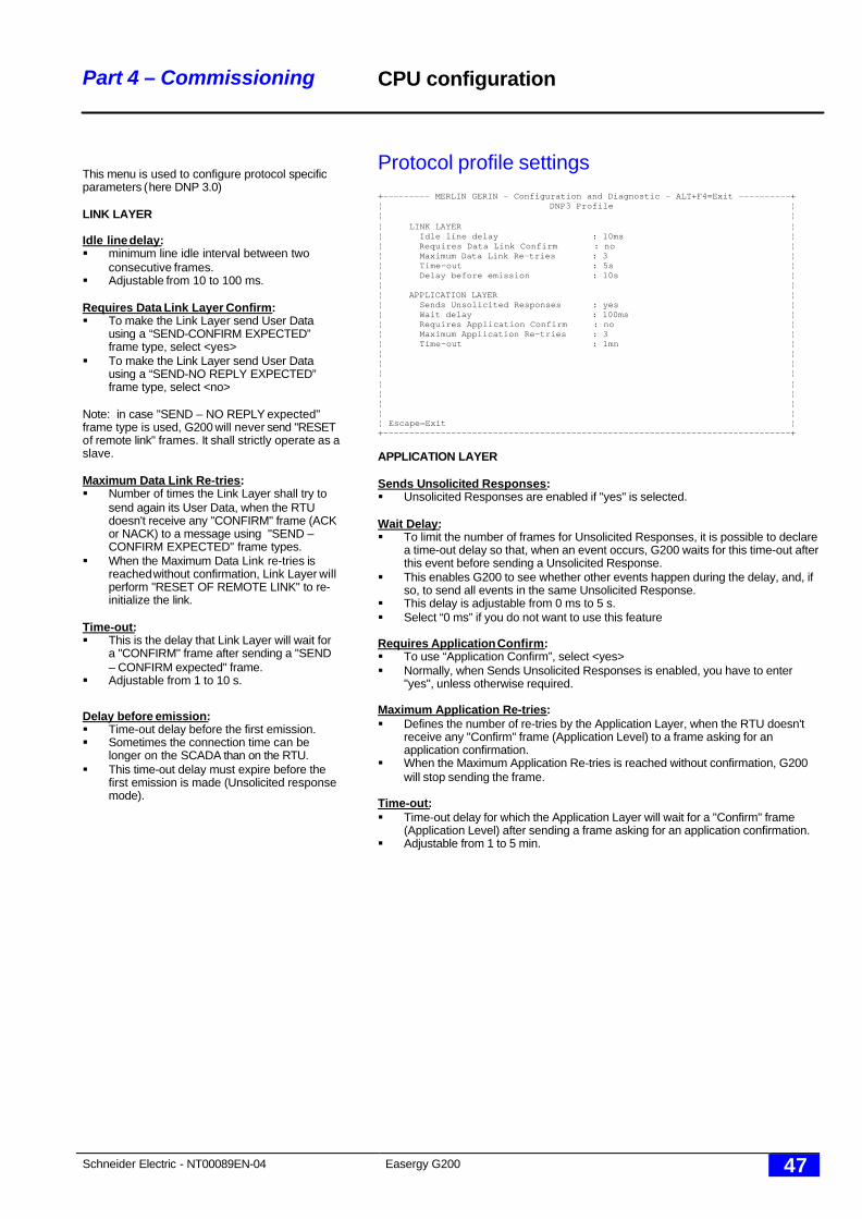
This menu is used to configure protocol specificparameters (here DNP 3.0)
LINK LAYER
Idle line delay:§ minimum line idle interval between two
consecutive frames.§ Adjustable from 10 to 100 ms.
Requires Data Link Layer Confirm:§ To make the Link Layer send User Data
using a “SEND-CONFIRM EXPECTED”frame type, select <yes>
§ To make the Link Layer send User Datausing a “SEND-NO REPLY EXPECTED”frame type, select <no>
Note: in case "SEND – NO REPLY expected"frame type is used, G200 will never send "RESETof remote link" frames. It shall strictly operate as aslave.
Maximum Data Link Re-tries:§ Number of times the Link Layer shall try to
send again its User Data, when the RTUdoesn't receive any "CONFIRM" frame (ACKor NACK) to a message using "SEND –CONFIRM EXPECTED" frame types.
§ When the Maximum Data Link re-tries isreached without confirmation, Link Layer willperform "RESET OF REMOTE LINK" to re-initialize the link.
Time-out:§ This is the delay that Link Layer will wait for
a "CONFIRM" frame after sending a "SEND– CONFIRM expected" frame.
§ Adjustable from 1 to 10 s.
Delay before emission:§ Time-out delay before the first emission.§ Sometimes the connection time can be
longer on the SCADA than on the RTU.§ This time-out delay must expire before the
first emission is made (Unsolicited responsemode).
CPU configuration
Protocol profile settings+--------- MERLIN GERIN - Configuration and Diagnostic - ALT+F4=Exit ----------+¦ DNP3 Profile ¦¦ ¦¦ LINK LAYER ¦¦ Idle line delay : 10ms ¦¦ Requires Data Link Confirm : no ¦¦ Maximum Data Link Re-tries : 3 ¦¦ Time-out : 5s ¦¦ Delay before emission : 10s ¦¦ ¦¦ APPLICATION LAYER ¦¦ Sends Unsolicited Responses : yes ¦¦ Wait delay : 100ms ¦¦ Requires Application Confirm : no ¦¦ Maximum Application Re-tries : 3 ¦¦ Time-out : 1mn ¦¦ ¦¦ ¦¦ ¦¦ ¦¦ ¦¦ ¦¦ ¦¦ Escape=Exit ¦+------------------------------------------------------------------------------+
APPLICATION LAYER
Sends Unsolicited Responses:§ Unsolicited Responses are enabled if "yes" is selected.
Wait Delay:§ To limit the number of frames for Unsolicited Responses, it is possible to declare
a time-out delay so that, when an event occurs, G200 waits for this time-out afterthis event before sending a Unsolicited Response.
§ This enables G200 to see whether other events happen during the delay, and, ifso, to send all events in the same Unsolicited Response.
§ This delay is adjustable from 0 ms to 5 s.§ Select “0 ms” if you do not want to use this feature
Requires Application Confirm:§ To use “Application Confirm”, select <yes>§ Normally, when Sends Unsolicited Responses is enabled, you have to enter
"yes", unless otherwise required.
Maximum Application Re-tries:§ Defines the number of re-tries by the Application Layer, when the RTU doesn't
receive any "Confirm" frame (Application Level) to a frame asking for anapplication confirmation.
§ When the Maximum Application Re-tries is reached without confirmation, G200will stop sending the frame.
Time-out:§ Time-out delay for which the Application Layer will wait for a "Confirm" frame
(Application Level) after sending a frame asking for an application confirmation.§ Adjustable from 1 to 5 min.
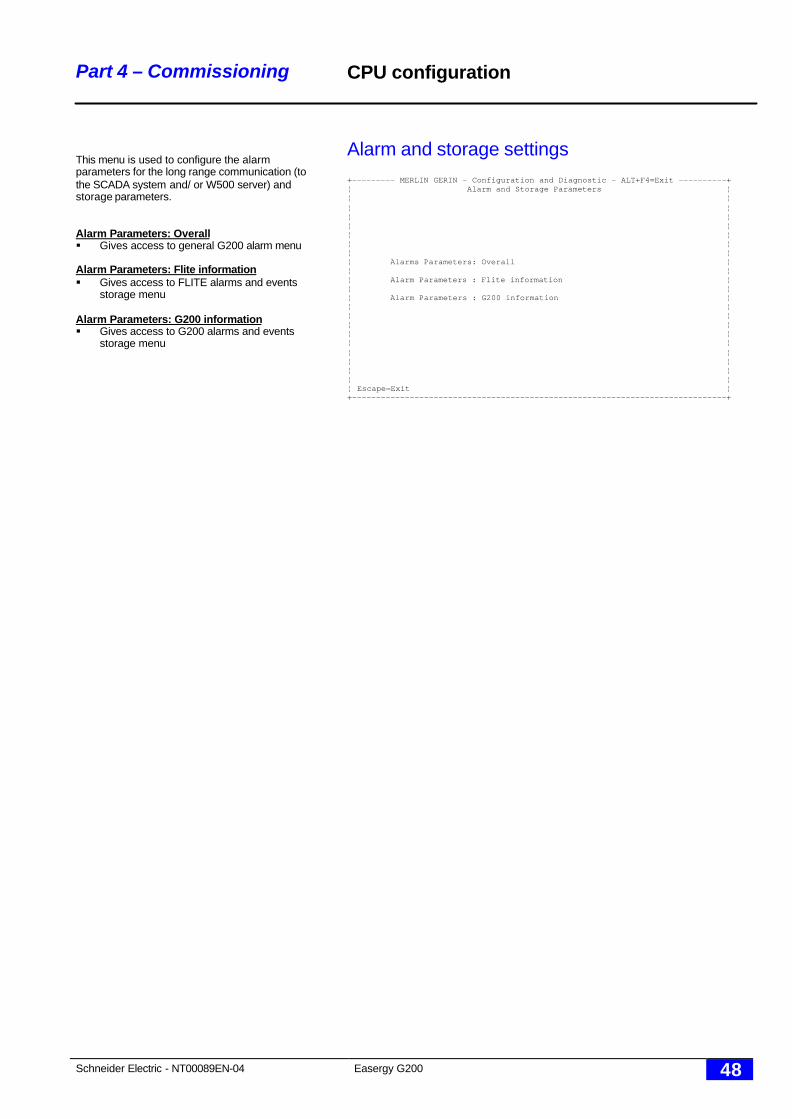
Schneider Electric - NT00089EN-04 Easergy G200 48
Part 4 – Commissioning
This menu is used to configure the alarmparameters for the long range communication (tothe SCADA system and/ or W500 server) andstorage parameters.
Alarm Parameters: Overall§ Gives access to general G200 alarm menu
Alarm Parameters: Flite information§ Gives access to FLITE alarms and events
storage menu
Alarm Parameters: G200 information§ Gives access to G200 alarms and events
storage menu
CPU configuration
Alarm and storage settings+--------- MERLIN GERIN - Configuration and Diagnostic - ALT+F4=Exit ----------+¦ Alarm and Storage Parameters ¦¦ ¦¦ ¦¦ ¦¦ ¦¦ ¦¦ ¦¦ ¦¦ Alarms Parameters: Overall ¦¦ ¦¦ Alarm Parameters : Flite information ¦¦ ¦¦ Alarm Parameters : G200 information ¦¦ ¦¦ ¦¦ ¦¦ ¦¦ ¦¦ ¦¦ ¦¦ ¦¦ ¦¦ Escape=Exit ¦+------------------------------------------------------------------------------+
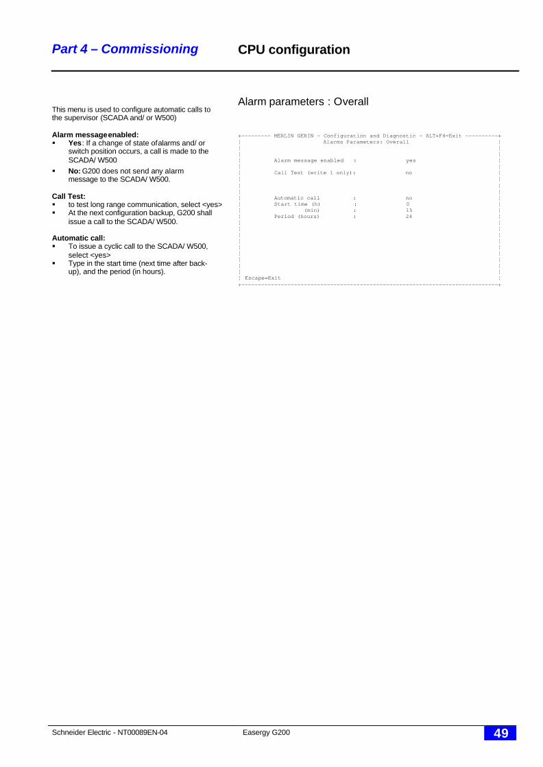
Schneider Electric - NT00089EN-04 Easergy G200 49
Part 4 – Commissioning
This menu is used to configure automatic calls tothe supervisor (SCADA and/ or W500)
Alarm message enabled:§ Yes: If a change of state of alarms and/ or
switch position occurs, a call is made to theSCADA/ W500
§ No: G200 does not send any alarmmessage to the SCADA/ W500.
Call Test:§ to test long range communication, select <yes>§ At the next configuration backup, G200 shall
issue a call to the SCADA/ W500.
Automatic call:§ To issue a cyclic call to the SCADA/ W500,
select <yes>§ Type in the start time (next time after back-
up), and the period (in hours).
CPU configuration
Alarm parameters : Overall
+--------- MERLIN GERIN - Configuration and Diagnostic - ALT+F4=Exit ----------+¦ Alarms Parameters: Overall ¦¦ ¦¦ ¦¦ Alarm message enabled : yes ¦¦ ¦¦ Call Test (write 1 only): no ¦¦ ¦¦ ¦¦ ¦¦ Automatic call : no ¦¦ Start time (h) : 0 ¦¦ (min) : 15 ¦¦ Period (hours) : 24 ¦¦ ¦¦ ¦¦ ¦¦ ¦¦ ¦¦ ¦¦ ¦¦ ¦¦ ¦¦ Escape=Exit ¦+------------------------------------------------------------------------------+
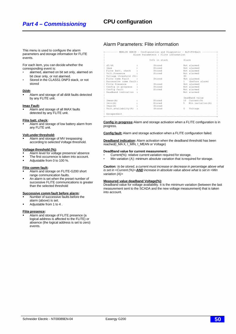
Schneider Electric - NT00089EN-04 Easergy G200 50
Part 4 – Commissioning
This menu is used to configure the alarmparameters and storage information for FLITEevents.
For each item, you can decide whether thecorresponding event is:• alarmed, alarmed on bit set only, alarmed on
bit clear only, or not alarmed.• Stored in the CLASS1 DNP3 stack, or not
stored
Di/dt:§ Alarm and storage of all di/dt faults detected
by any FLITE unit.
Imax Fault:§ Alarm and storage of all IMAX faults
detected by any FLITE unit.
Flite batt. check:§ Alarm and storage of low battery alarm from
any FLITE unit.
Volt.under threshold:§ Alarm and storage of MV trespassing
according to selected Voltage threshold.
Voltage threshold (%):§ Alarm level for voltage presence/ absence§ The first occurrence is taken into account.§ Adjustable from 0 to 100 %.
Flite comm fault:§ Alarm and storage on FLITE-G200 short
range communication faults.§ An alarm is set when the preset number of
successive FLITE communications is greaterthan the selected threshold
Successive comm fault before alarm:§ Number of successive faults before the
alarm (above) is set.§ Adjustable from 1 to 4 .
Flite presence:§ Alarm and storage of FLITE presence (a
logical address is affected to the FLITE) orabsence (the logical address is set to zero)events.
CPU configuration
Alarm Parameters: Flite information+--------- MERLIN GERIN - Configuration and Diagnostic - ALT+F4=Exit ----------+¦ Alarm Parameters : Flite information ¦¦ ¦¦ Info in stack Alarm ¦¦ ¦¦ dI/dt : Stored Not alarmed ¦¦ Imax : Stored Not alarmed ¦¦ Flite Batt. check : Stored Not alarmed ¦¦ Volt.Presence : Stored Not alarmed ¦¦ Voltage threshold (%): 80 ¦¦ Flite Comm Fault : Stored Not alarmed ¦¦ Successive comm fault: 1 (before alarm) ¦¦ Flite Presence : Stored Not alarmed ¦¦ Config in progress : Stored Not alarmed ¦¦ Config fault : Stored Not alarmed ¦¦ Deadband indication : Not alarmed ¦¦ ¦¦ DeadBand value ¦¦ Imean(A) : Stored 10 Current(%) ¦¦ Imin(A) : Stored 5 Min variation(A) ¦¦ Imax(A) : Stored ¦¦ Volt.availabilty(%) : Stored 0 Voltage ¦¦ ¦¦ Escape=Exit ¦+------------------------------------------------------------------------------+
Config in progress: Alarm and storage activation when a FLITE configuration is inprogress.
Config fault: Alarm and storage activation when a FLITE configuration failed.
Deadband indication: Alarm activation when the deadband threshold has beenreached(I_MA X, I_MIN, I_MEAN or Voltage)
DeadBand value for current measurement:• Current(%): relative current variation required for storage.• Min variation (A): minimum absolute variation that is required for storage.
Caution: to be stored, a current must increase or decrease in percentage above whatis set in <Current (%)> AND increase in absolute value above what is set in <Minvariation (A)>
Measured value deadband Voltage(%):Deadband value for voltage availability. It is the minimum variation (between the lastmeasurement sent to the SCADA and the new voltage measurement) that is takeninto account.
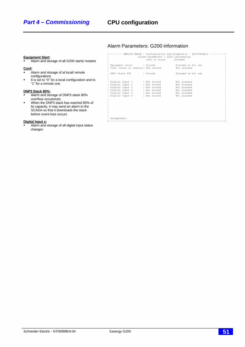
Schneider Electric - NT00089EN-04 Easergy G200 51
Part 4 – Commissioning
Equipment Start:§ Alarm and storage of all G200 starts/ restarts
Conf:§ Alarm and storage of al local/ remote
configurations§ It is set to “0” for a local configuration and to
“1” for a remote one
DNP3 Stack 80%:§ Alarm and storage of DNP3 stack 80%
overflow occurences§ When the DNP3 stack has reached 80% of
its capacity, it may send an alarm to theSCADA so that it downloads the stackbefore event loss occurs
Digital Input x:§ Alarm and storage of all digital input status
changes
CPU configuration
Alarm Parameters: G200 information+--------- MERLIN GERIN - Configuration and Diagnostic - ALT+F4=Exit ----------+¦ Alarm Parameters : G200 information ¦¦ Info in stack Alarmed ¦¦ ¦¦ Equipment Start : Stored Alarmed on bit set ¦¦ Conf (local or remote): Not stored Not alarmed ¦¦ ¦¦ DNP3 Stack 80% : Stored Alarmed on bit set ¦¦ ¦¦ ¦¦ Digital Input 1 : Not stored Not alarmed ¦¦ Digital Input 2 : Not stored Not alarmed ¦¦ Digital Input 3 : Not stored Not alarmed ¦¦ Digital Input 4 : Not stored Not alarmed ¦¦ Digital Input 5 : Not stored Not alarmed ¦¦ Digital Input 6 : Not stored Not alarmed ¦¦ ¦¦ ¦¦ ¦¦ ¦¦ ¦¦ ¦¦ ¦¦ Escape=Exit ¦+------------------------------------------------------------------------------+
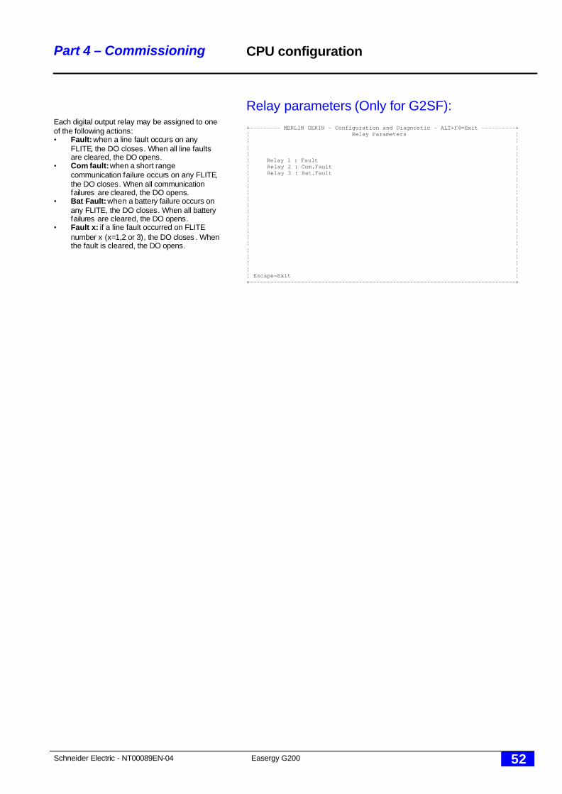
Schneider Electric - NT00089EN-04 Easergy G200 52
Part 4 – Commissioning
Each digital output relay may be assigned to oneof the following actions:• Fault: when a line fault occurs on any
FLITE, the DO closes. When all line faultsare cleared, the DO opens.
• Com fault: when a short rangecommunication failure occurs on any FLITE,the DO closes. When all communicationfailures are cleared, the DO opens.
• Bat Fault: when a battery failure occurs onany FLITE, the DO closes. When all batteryfailures are cleared, the DO opens.
• Fault x: if a line fault occurred on FLITEnumber x (x=1,2 or 3), the DO closes . Whenthe fault is cleared, the DO opens.
CPU configuration
Relay parameters (Only for G2SF):+--------- MERLIN GERIN - Configuration and Diagnostic - ALT+F4=Exit ----------+¦ Relay Parameters ¦¦ ¦¦ ¦¦ ¦¦ Relay 1 : Fault ¦¦ Relay 2 : Com.Fault ¦¦ Relay 3 : Bat.Fault ¦¦ ¦¦ ¦¦ ¦¦ ¦¦ ¦¦ ¦¦ ¦¦ ¦¦ ¦¦ ¦¦ ¦¦ ¦¦ ¦¦ ¦¦ ¦¦ Escape=Exit ¦+------------------------------------------------------------------------------+
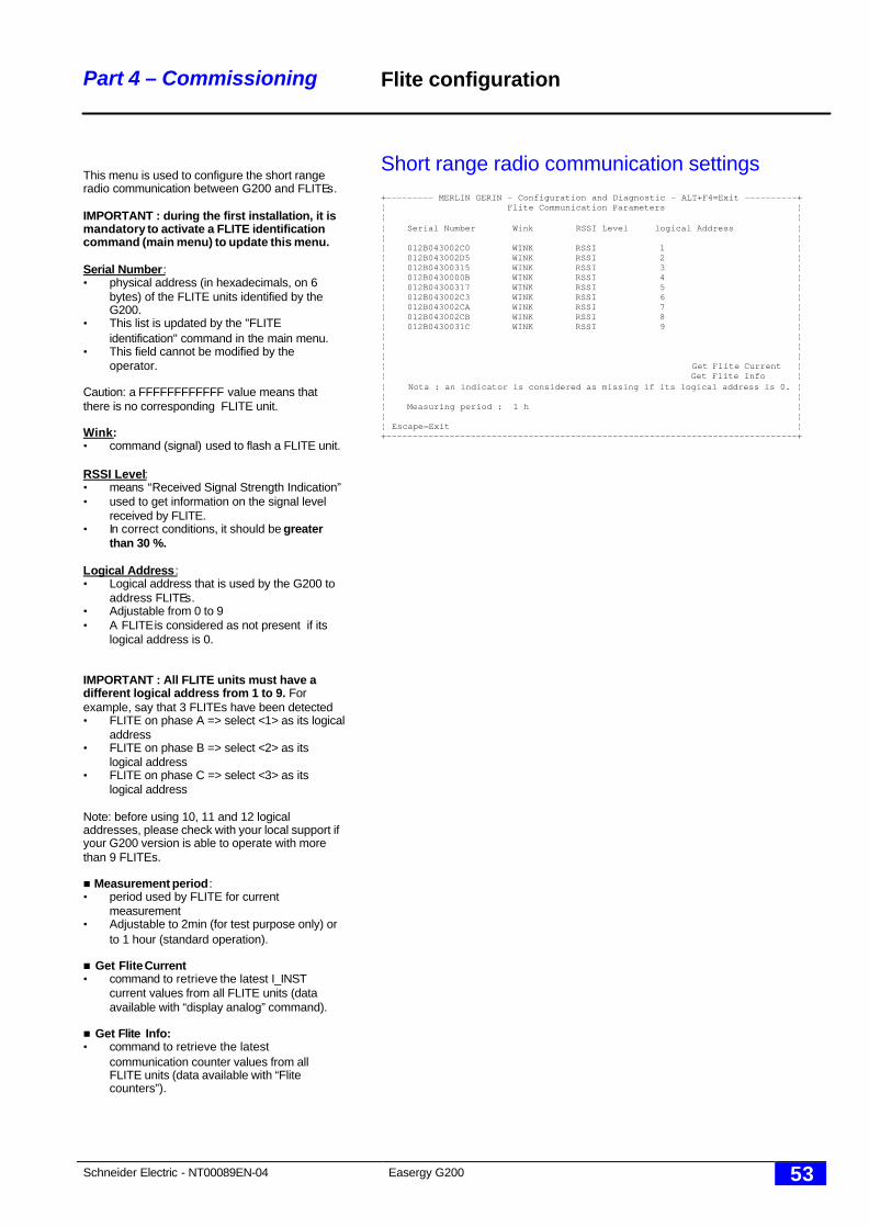
Schneider Electric - NT00089EN-04 Easergy G200 53
Part 4 – Commissioning
This menu is used to configure the short rangeradio communication between G200 and FLITEs.
IMPORTANT : during the first installation, it ismandatory to activate a FLITE identificationcommand (main menu) to update this menu.
Serial Number:• physical address (in hexadecimals, on 6
bytes) of the FLITE units identified by theG200.
• This list is updated by the "FLITEidentification" command in the main menu.
• This field cannot be modified by theoperator.
Caution: a FFFFFFFFFFFF value means thatthere is no corresponding FLITE unit.
Wink:• command (signal) used to flash a FLITE unit.
RSSI Level:• means “Received Signal Strength Indication”• used to get information on the signal level
received by FLITE.• In correct conditions, it should be greater
than 30 %.
Logical Address:• Logical address that is used by the G200 to
address FLITEs.• Adjustable from 0 to 9• A FLITE is considered as not present if its
logical address is 0.
IMPORTANT : All FLITE units must have adifferent logical address from 1 to 9. Forexample, say that 3 FLITEs have been detected• FLITE on phase A => select <1> as its logical
address• FLITE on phase B => select <2> as its
logical address• FLITE on phase C => select <3> as its
logical address
Note: before using 10, 11 and 12 logicaladdresses, please check with your local support ifyour G200 version is able to operate with morethan 9 FLITEs.
n Measurement period:• period used by FLITE for current
measurement• Adjustable to 2min (for test purpose only) or
to 1 hour (standard operation).
n Get Flite Current• command to retrieve the latest I_INST
current values from all FLITE units (dataavailable with “display analog” command).
n Get Flite Info:• command to retrieve the latest
communication counter values from allFLITE units (data available with “Flitecounters”).
Flite configuration
Short range radio communication settings+--------- MERLIN GERIN - Configuration and Diagnostic - ALT+F4=Exit ----------+¦ Flite Communication Parameters ¦¦ ¦¦ Serial Number Wink RSSI Level logical Address ¦¦ ¦¦ 012B043002C0 WINK RSSI 1 ¦¦ 012B043002D5 WINK RSSI 2 ¦¦ 012B04300315 WINK RSSI 3 ¦¦ 012B0430000B WINK RSSI 4 ¦¦ 012B04300317 WINK RSSI 5 ¦¦ 012B043002C3 WINK RSSI 6 ¦¦ 012B043002CA WINK RSSI 7 ¦¦ 012B043002CB WINK RSSI 8 ¦¦ 012B0430031C WINK RSSI 9 ¦¦ ¦¦ ¦¦ ¦¦ Get Flite Current ¦¦ Get Flite Info ¦¦ Nota : an indicator is considered as missing if its logical address is 0. ¦¦ ¦¦ Measuring period : 1 h ¦¦ ¦¦ Escape=Exit ¦+------------------------------------------------------------------------------+
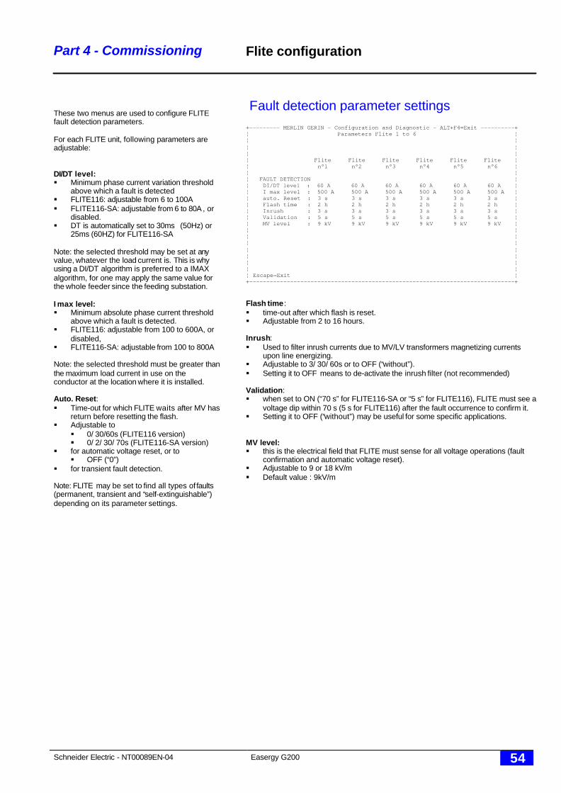
Schneider Electric - NT00089EN-04 Easergy G200 54
Part 4 - Commissioning
These two menus are used to configure FLITEfault detection parameters.
For each FLITE unit, following parameters areadjustable:
DI/DT level:§ Minimum phase current variation threshold
above which a fault is detected§ FLITE116: adjustable from 6 to 100A§ FLITE116-SA: adjustable from 6 to 80A , or
disabled.§ DT is automatically set to 30ms (50Hz) or
25ms (60HZ) for FLITE116-SA
Note: the selected threshold may be set at anyvalue, whatever the load current is. This is whyusing a DI/DT algorithm is preferred to a IMAXalgorithm, for one may apply the same value forthe whole feeder since the feeding substation.
I max level:§ Minimum absolute phase current threshold
above which a fault is detected.§ FLITE116: adjustable from 100 to 600A, or
disabled,§ FLITE116-SA: adjustable from 100 to 800A
Note: the selected threshold must be greater thanthe maximum load current in use on theconductor at the location where it is installed.
Auto. Reset:§ Time-out for which FLITE waits after MV has
return before resetting the flash.§ Adjustable to
§ 0/ 30/60s (FLITE116 version)§ 0/ 2/ 30/ 70s (FLITE116-SA version)
§ for automatic voltage reset, or to§ OFF (“0”)
§ for transient fault detection.
Note: FLITE may be set to find all types of faults(permanent, transient and “self-extinguishable”)depending on its parameter settings.
Flite configuration
Fault detection parameter settings+--------- MERLIN GERIN - Configuration and Diagnostic - ALT+F4=Exit ----------+¦ Parameters Flite 1 to 6 ¦¦ ¦¦ ¦¦ ¦¦ Flite Flite Flite Flite Flite Flite ¦¦ n°1 n°2 n°3 n°4 n°5 n°6 ¦¦ ¦¦ FAULT DETECTION ¦¦ DI/DT level : 60 A 60 A 60 A 60 A 60 A 60 A ¦¦ I max level : 500 A 500 A 500 A 500 A 500 A 500 A ¦¦ auto. Reset : 3 s 3 s 3 s 3 s 3 s 3 s ¦¦ Flash time : 2 h 2 h 2 h 2 h 2 h 2 h ¦¦ Inrush : 3 s 3 s 3 s 3 s 3 s 3 s ¦¦ Validation : 5 s 5 s 5 s 5 s 5 s 5 s ¦¦ MV level : 9 kV 9 kV 9 kV 9 kV 9 kV 9 kV ¦¦ ¦¦ ¦¦ ¦¦ ¦¦ ¦¦ ¦¦ ¦¦ Escape=Exit ¦+------------------------------------------------------------------------------+
Flash time :§ time-out after which flash is reset.§ Adjustable from 2 to 16 hours.
Inrush:§ Used to filter inrush currents due to MV/LV transformers magnetizing currents
upon line energizing.§ Adjustable to 3/ 30/ 60s or to OFF (“without”).§ Setting it to OFF means to de-activate the inrush filter (not recommended)
Validation:§ when set to ON (“70 s” for FLITE116-SA or “5 s” for FLITE116), FLITE must see a
voltage dip within 70 s (5 s for FLITE116) after the fault occurrence to confirm it.§ Setting it to OFF (“without”) may be useful for some specific applications.
MV level:§ this is the electrical field that FLITE must sense for all voltage operations (fault
confirmation and automatic voltage reset).§ Adjustable to 9 or 18 kV/m§ Default value : 9kV/m

Schneider Electric - NT00089EN-04 Easergy G200 55
Part 5 - Maintenance
Part 5Maintenance
Schneider Electric - NT00089EN-04 Easergy G200 56
Part 5 - Maintenance Introduction
General information
The equipment does not require regular maintenance.It is also advisable (even essential) to have a computer (PC compatible) and thediskette or CDROM (G200 Configuration and diagnosis) for all equipment servicing.Specific maintenance type information is available only on this diskette/ CDROM:
o reading of internal equipment states,o reading of stored events.NB: spare fuses are available in the "accessory" bags attached to the inside of thebasic enclosure.
Connecting the computer and using the software
See chapter “commissioning”
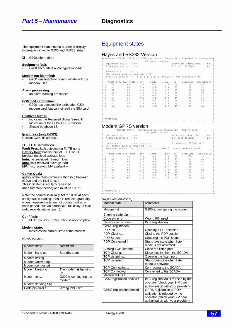
Schneider Electric - NT00089EN-04 Easergy G200 57
Part 5 – Maintenance
The equipment states menu is used to displayinformation linked to G200 and FLITES state.
q G200 information:
Equipment fault:• G200 encounters a configuration fault.
Modem not identified:• G200 was unable to communicate with the
modem used.
Alarm processing:• an alarm is being processed.
GSM SIM card failure:• G200 has detected the embedded GSM
modem card, but cannot read the SIM card.
Received signal:• indicates the Received Signal Strength
Indication of the GSM/ GPRS modem.• Should be above 16.
Ip address (only GPRS):Current G200 IP address.
q FLITE information:Fault Pres.: fault detected on FLITE no. xBattery fault: battery fault of FLITE no. XIav: last received average loadImin: last received minimum loadImax: last received average loadMV: last received MV availability
Comm Qual.:quality of the radio communication (%) betweentG200 and the FLITE no. x.This indicator is regularly refreshed(measurement period) and must be 100 %
Note: the counter is initially set to 100% at eachconfiguration loading, then it is reduced graduallywhen measurements are not updated within aeach period (plus an additional 2 mn delay to takeradio repeats into account ).
Conf fault:• FLITE no. <X> configuration is not complete.
Modem state:• indicates the current state of the modem
Hayes version:
Modem state comments
Modem hang up Standby state
Modem calling... -Modem answering... -Modem connected -Modem breaking The modem is hanging
upModem Init... G200 is configuring the
modemModem sending SMS...Code pin error ! Wrong PIN used
Diagnostics
Equipment states
Hayes and RS232 Version+--------- MERLIN GERIN - Configuration and Diagnostic - ALT+F4=Exit ----------+¦ Equipment states ¦¦ Equipment Fault : no Modem not identified no ¦¦ Alarm processing : no SIM card failure no ¦¦ ¦¦ Modem state : ¦¦ GSM signal quality:(must be > 16) ¦¦ received signal: 0 ¦¦¦¦¦¦¦¦¦¦¦¦¦¦¦¦ Max(31) - Not detectable(99) ¦¦ ¦¦ Fault Pres Bat.Fault I ave I min I max MV Comm.Qual Conf.Fault ¦¦ 1 no no 0 A 0 A 0 A 0% 0% no ¦¦ 2 no no 0 A 0 A 0 A 0% 0% no ¦¦ 3 no no 0 A 0 A 0 A 0% 0% no ¦¦ 4 no no 0 A 0 A 0 A 0% 0% no ¦¦ 5 no no 0 A 0 A 0 A 0% 0% no ¦¦ 6 no no 0 A 0 A 0 A 0% 0% no ¦¦ 7 no no 0 A 0 A 0 A 0% 0% no ¦¦ 8 no no 0 A 0 A 0 A 0% 0% no ¦¦ 9 no no 0 A 0 A 0 A 0% 0% no ¦¦ ¦¦ ¦¦ ¦¦ ¦¦ ESCAPE=Exit ¦+------------------------------------------------------------------------------+
Modem GPRS version+--------- MERLIN GERIN - Configuration and Diagnostic - ALT+F4=Exit ----------+¦ Equipment states ¦¦ Equipment Fault : no Modem not identified no ¦¦ Alarm processing : no SIM card failure no ¦¦ ¦¦ Modem state : ppp connected Ip adress : 192.68.12.6 ¦¦ GSM signal quality:(must be > 16) ¦¦ received signal: 0 ¦¦¦¦¦¦¦¦¦¦¦¦¦¦¦¦ Max(31) - Not detectable(99) ¦¦ ¦¦ Fault Pres Bat.Fault I ave I min I max MV Comm.Qual Conf.Fault ¦¦ 1 no no 0 A 0 A 0 A 0% 0% no ¦¦ 2 no no 0 A 0 A 0 A 0% 0% no ¦¦ 3 no no 0 A 0 A 0 A 0% 0% no ¦¦ 4 no no 0 A 0 A 0 A 0% 0% no ¦¦ 5 no no 0 A 0 A 0 A 0% 0% no ¦¦ 6 no no 0 A 0 A 0 A 0% 0% no ¦¦ 7 no no 0 A 0 A 0 A 0% 0% no ¦¦ 8 no no 0 A 0 A 0 A 0% 0% no ¦¦ 9 no no 0 A 0 A 0 A 0% 0% no ¦¦ ¦¦ ¦¦ ¦¦ ¦¦ ESCAPE=Exit ¦+------------------------------------------------------------------------------+
Hayes version (contd):Modem state comments
Modem Init... G200 is configuring the modem
Entering code pin... -Code pin error ! Wrong PIN usedNetwork registration... IMSI registrationGPRS registration...PDP Init... Opening a PDP sessionPDP Closing... Closing the PDP sessionPDP Status... Checking the PDP statusPDP Connected ! Stand-bye state when listen
mode is not activated.Closing TCP listened Close the listen portTCP Closing... Disconnection from the SCADATCP Listening... Opening the listen portTCP Listened ! Stand-bye state when listen
mode is activated.TCP Connecting... Connecting to the SCADATCP Connected ! Connected to the SCADAModem failure !GSM registration denied ! IMSI registration is refused by the
operator (check your SIM cardauthorization with your provider)
GPRS registration denied ! GPRS registration or PDPactivation is refused by theoperator (check your SIM cardauthorization with your provider)
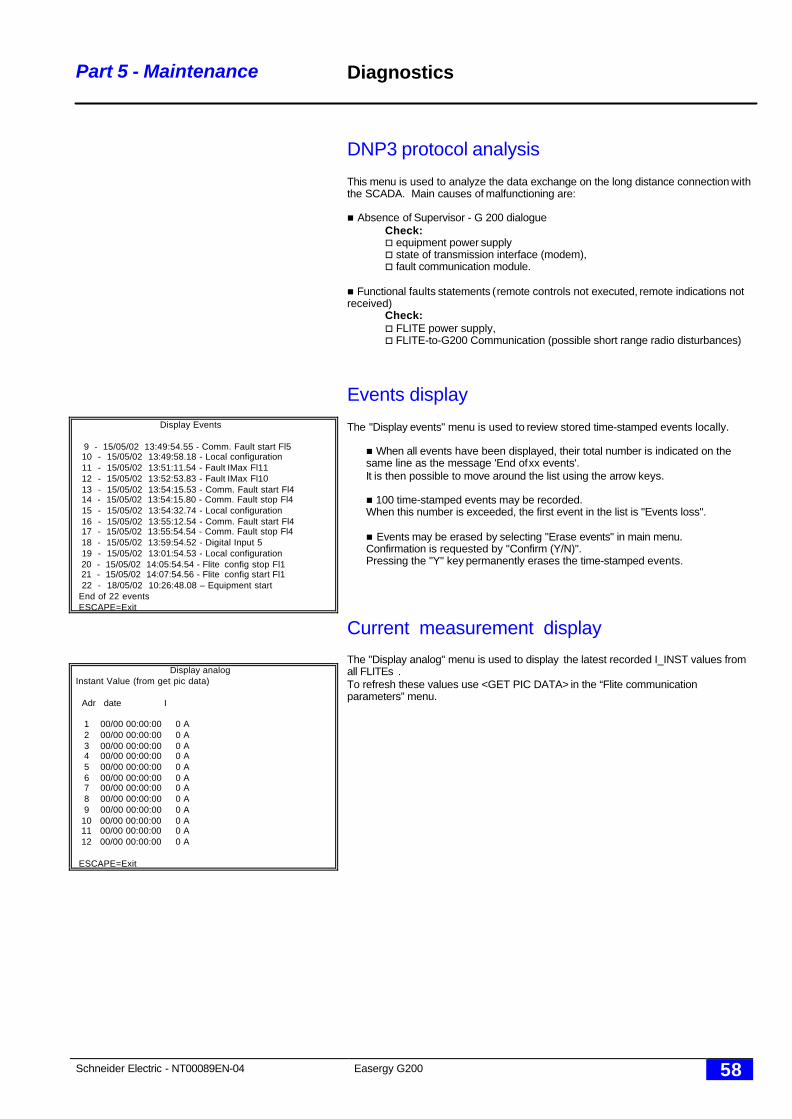
Schneider Electric - NT00089EN-04 Easergy G200 58
Part 5 - Maintenance
Display Events
9 - 15/05/02 13:49:54.55 - Comm. Fault start Fl5 10 - 15/05/02 13:49:58.18 - Local configuration 11 - 15/05/02 13:51:11.54 - Fault IMax Fl11 12 - 15/05/02 13:52:53.83 - Fault IMax Fl10 13 - 15/05/02 13:54:15.53 - Comm. Fault start Fl4 14 - 15/05/02 13:54:15.80 - Comm. Fault stop Fl4 15 - 15/05/02 13:54:32.74 - Local configuration 16 - 15/05/02 13:55:12.54 - Comm. Fault start Fl4 17 - 15/05/02 13:55:54.54 - Comm. Fault stop Fl4 18 - 15/05/02 13:59:54.52 - Digital Input 5 19 - 15/05/02 13:01:54.53 - Local configuration 20 - 15/05/02 14:05:54.54 - Flite config stop Fl1 21 - 15/05/02 14:07:54.56 - Flite config start Fl1 22 - 18/05/02 10:26:48.08 – Equipment start End of 22 events ESCAPE=Exit
Display analogInstant Value (from get pic data)
Adr date I
1 00/00 00:00:00 0 A 2 00/00 00:00:00 0 A 3 00/00 00:00:00 0 A 4 00/00 00:00:00 0 A 5 00/00 00:00:00 0 A 6 00/00 00:00:00 0 A 7 00/00 00:00:00 0 A 8 00/00 00:00:00 0 A 9 00/00 00:00:00 0 A 10 00/00 00:00:00 0 A 11 00/00 00:00:00 0 A 12 00/00 00:00:00 0 A
ESCAPE=Exit
Diagnostics
DNP3 protocol analysis
This menu is used to analyze the data exchange on the long distance connection withthe SCADA. Main causes of malfunctioning are:
n Absence of Supervisor - G 200 dialogueCheck:o equipment power supplyo state of transmission interface (modem),o fault communication module.
n Functional faults statements (remote controls not executed, remote indications notreceived)
Check:o FLITE power supply,o FLITE-to-G200 Communication (possible short range radio disturbances)
Events display
The "Display events" menu is used to review stored time-stamped events locally.
n When all events have been displayed, their total number is indicated on thesame line as the message 'End of xx events'.It is then possible to move around the list using the arrow keys.
n 100 time-stamped events may be recorded.When this number is exceeded, the first event in the list is "Events loss".
n Events may be erased by selecting "Erase events" in main menu.Confirmation is requested by "Confirm (Y/N)".Pressing the "Y" key permanently erases the time-stamped events.
Current measurement display
The "Display analog" menu is used to display the latest recorded I_INST values fromall FLITEs .To refresh these values use <GET PIC DATA> in the “Flite communicationparameters” menu.
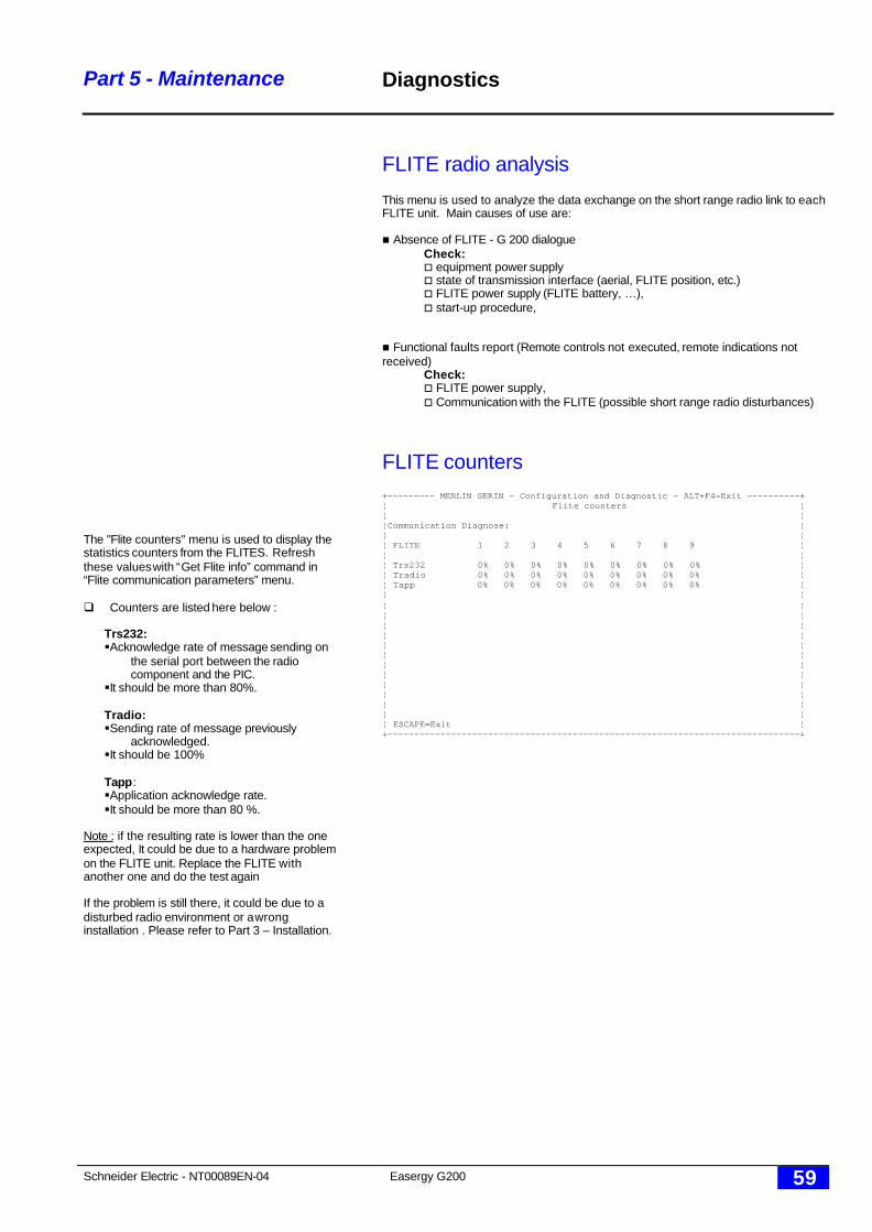
Schneider Electric - NT00089EN-04 Easergy G200 59
Part 5 - Maintenance
The "Flite counters" menu is used to display thestatistics counters from the FLITES. Refreshthese values with “Get Flite info” command in“Flite communication parameters” menu.
q Counters are listed here below :
Trs232:§ Acknowledge rate of message sending on
the serial port between the radiocomponent and the PIC.
§ It should be more than 80%.
Tradio:§ Sending rate of message previously
acknowledged.§ It should be 100%
Tapp:§ Application acknowledge rate.§ It should be more than 80 %.
Note : if the resulting rate is lower than the oneexpected, It could be due to a hardware problemon the FLITE unit. Replace the FLITE withanother one and do the test again
If the problem is still there, it could be due to adisturbed radio environment or a wronginstallation . Please refer to Part 3 – Installation.
Diagnostics
FLITE radio analysis
This menu is used to analyze the data exchange on the short range radio link to eachFLITE unit. Main causes of use are:
n Absence of FLITE - G 200 dialogueCheck:o equipment power supplyo state of transmission interface (aerial, FLITE position, etc.)o FLITE power supply (FLITE battery, …),o start-up procedure,
n Functional faults report (Remote controls not executed, remote indications notreceived)
Check:o FLITE power supply,o Communication with the FLITE (possible short range radio disturbances)
FLITE counters+--------- MERLIN GERIN - Configuration and Diagnostic - ALT+F4=Exit ----------+¦ Flite counters ¦¦ ¦¦Communication Diagnose: ¦¦ ¦¦ FLITE 1 2 3 4 5 6 7 8 9 ¦¦ ¦¦ Trs232 0% 0% 0% 0% 0% 0% 0% 0% 0% ¦¦ Tradio 0% 0% 0% 0% 0% 0% 0% 0% 0% ¦¦ Tapp 0% 0% 0% 0% 0% 0% 0% 0% 0% ¦¦ ¦¦ ¦¦ ¦¦ ¦¦ ¦¦ ¦¦ ¦¦ ¦¦ ¦¦ ¦¦ ¦¦ ¦¦ ¦¦ ESCAPE=Exit ¦+------------------------------------------------------------------------------+

Schneider Electric - NT00089EN-04 Easergy G200 60
Easergy G200 Personal notes
NT00089EN-04 10/03/2005
Easergy G200
Easergy
Postal addressF-38050 Grenoble Cedex 9 – FranceTel. : +33 4 76 57 60 60Fax : +33 4 76 57 60 61http://ww.easergy.comhttp://www.schneiderelectric.comRCS Nanterre B 954 503 439
As standards, specifications and design change from time to time, always askfor confirmation of the information given in this publication.
Published by : Schneider ElectricLayed out by : jypPrinted by : Print date :