g803 software manual - ae2 · manuale per software g803 ae2 snc sovico (mi) italy 14/10/09 9...
TRANSCRIPT

Manuale per software G803 AE2 snc Sovico (MI) Italy 14/10/09
1
G803 Software manual
This software is an instrument that permits to see and import all data on computer maintaining the database
of all the executed tests.
INDEX • Program installation………………………………………………………………………………… page 2
• USB driver installation……………………………………………………………………………… 6
• Function description………………………………………………………………………………… 9
• Chapter 1 Config………………………………………………….…………………….. 9 1.1 Operators……………………………………………………………………. 10
1.2 Classes………………………………………………………………………. 10 1.3 Equipments………………………………………………………………….. 11 1.4 Compensation………………………………………………………………. 12 1.5 Report options………………………………………………………………. 12 1.6 Report headers……………………………………………………………… 12 1.7 Report notes………………………………………………………………… 13 1.8 Settings…………………………………………………………………..….. 13
• Chapter 2 Models……………………………………………………………..……….... 13 2.1 How to create a new model...……………………………………………… 13 2.2 How to modify a model……………………………………………………… 14 2.3 How to cancell a model…………………………………………………….. 14
• Chapter 3 Equipments………………………………………………………………….. 14
• Chapter 4 Test…………………………………………………………………………… 15
• Chapter 5 Reports………………………………………………………………………. 17 5.1 Database…………………………………………………………………….. 17
5.2 Magnetization curve………………………………………………………… 18 5.3 Safety factor and Composite Error……………………………………….. 18
• Chapter 6 Glossary……………………………………………………………………… 19

Manuale per software G803 AE2 snc Sovico (MI) Italy 14/10/09
2
PROGRAM INSTALLATION
- Make double pressure on “install_Ae2_1.32.zip” - Make double pressure on “install_Ae2_1.32.exe” - Press “NEXT”
- Insert the User Name and the Company name into the proper areas then press “NEXT”

Manuale per software G803 AE2 snc Sovico (MI) Italy 14/10/09
3
- Choose the installation's destination folder (directory); if you need to change the automatic directory folder, make pressure on "change" then press “NEXT”.
- Maintain the selected setup type “NORMAL INSTALL” then press “NEXT”

Manuale per software G803 AE2 snc Sovico (MI) Italy 14/10/09
4
- Make pressure on “INSTALL”
- Once the installation operation is completed, press “FINISH”
- Then open the program making double pressure on “AE2 Link G803” icon present on the desktop and
press “COPY TO CLIPBOARD” or send the code (by e.mail) to the following address: [email protected]

Manuale per software G803 AE2 snc Sovico (MI) Italy 14/10/09
5
- Insert the code (transmitted by the supplier), on the bottom area “ENTER ACTIVATION CODE”, then press “OK”
Validity code information will be displayed as well as the program duration, then make pressure on “OK”
At this moment the program will be automatically open and the following display will be showed:
Once the validity time expire, it is necessary to repeat the code insertion operation.

Manuale per software G803 AE2 snc Sovico (MI) Italy 14/10/09
6
USB DRIVER INSTALLATION To install the driver, connect the Comparator to the PC by an USB cable; a new hardware will be automatically noticed and the following screen will appears; now press " No non ora" then make pressure on "avanti".
- Now select “INSTALLA DA UN ELENCO O PERCORSO SPECIFICO (PER UTENTI ESPERTI)”, then press “avanti”
Manuale per software G803 AE2 snc Sovico (MI) Italy 14/10/09
7
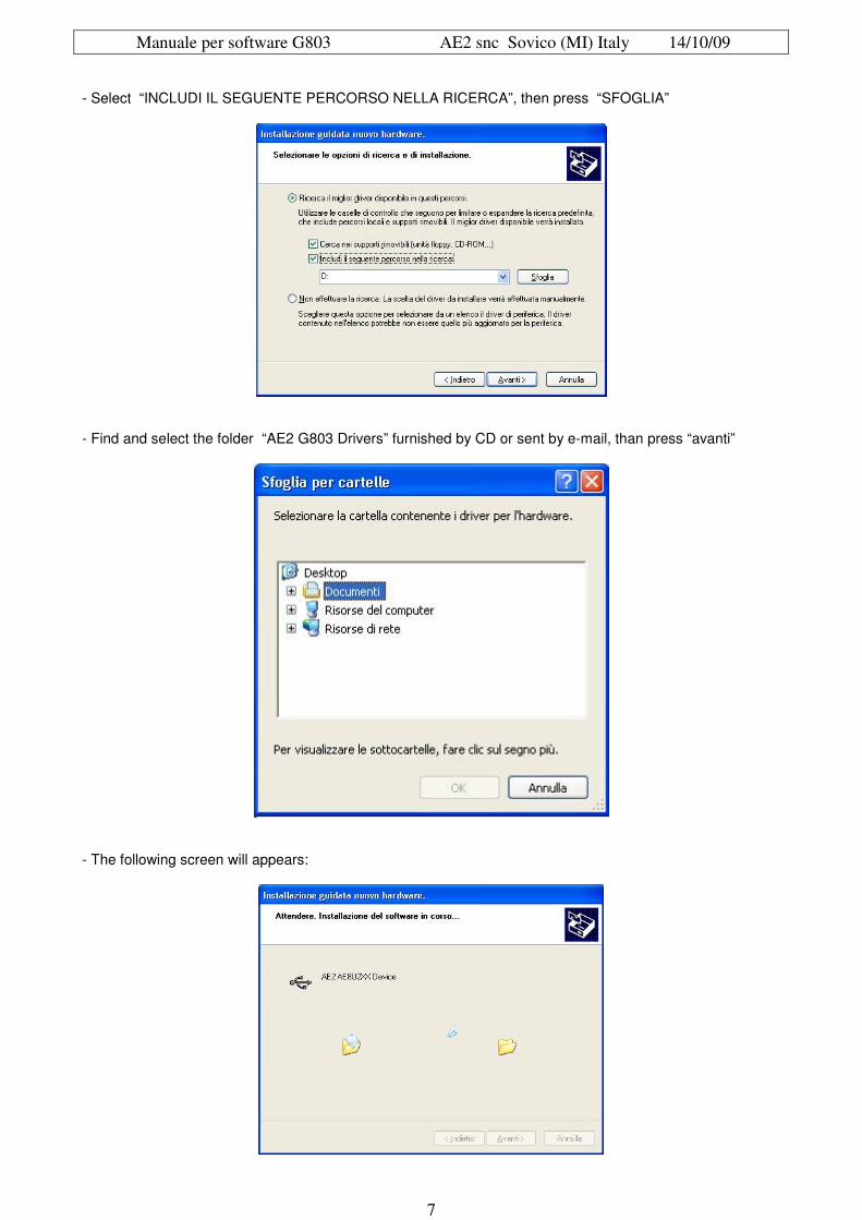
- Select “INCLUDI IL SEGUENTE PERCORSO NELLA RICERCA”, then press “SFOGLIA”
- Find and select the folder “AE2 G803 Drivers” furnished by CD or sent by e-mail, than press “avanti”
- The following screen will appears:
Manuale per software G803 AE2 snc Sovico (MI) Italy 14/10/09
8
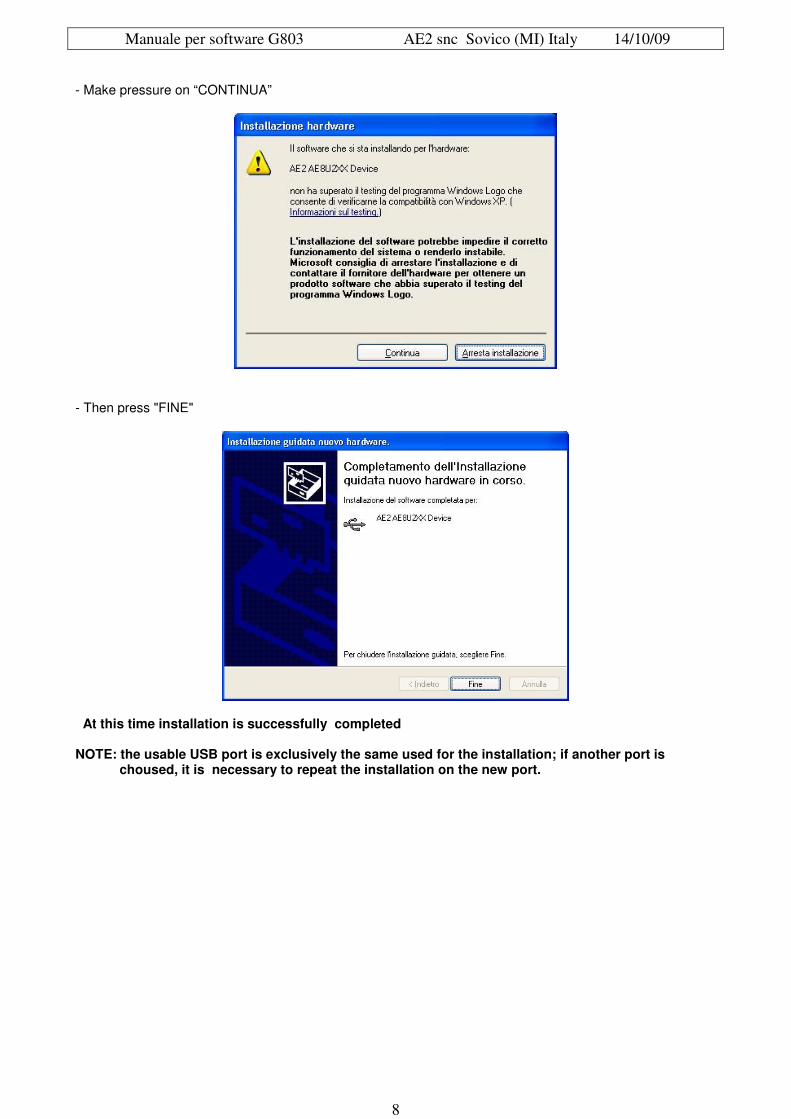
- Make pressure on “CONTINUA”
- Then press "FINE"
At this time installation is successfully completed NOTE: the usable USB port is exclusively the same used for the installation; if another port is choused, it is necessary to repeat the installation on the new port.
Manuale per software G803 AE2 snc Sovico (MI) Italy 14/10/09
9
FUNCTIONS DESCRIPTIONS
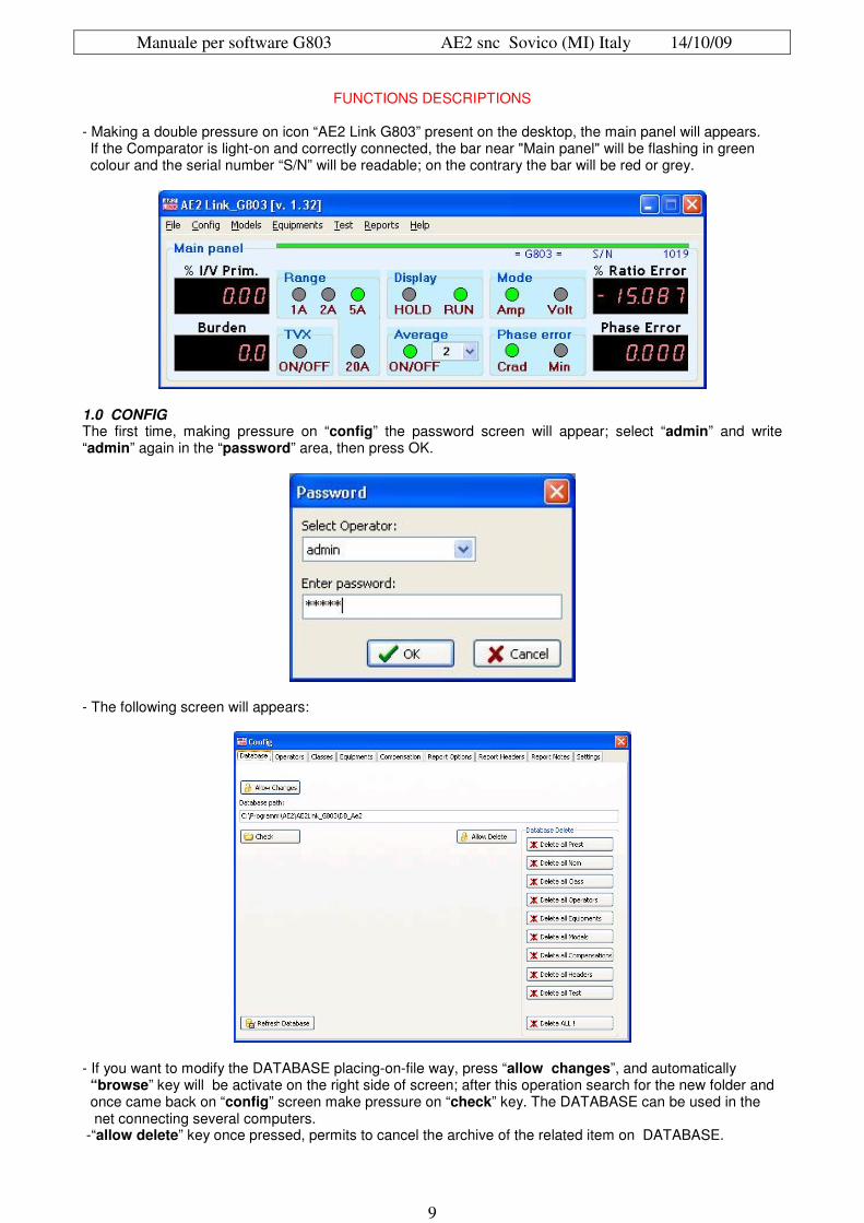
- Making a double pressure on icon “AE2 Link G803” present on the desktop, the main panel will appears. If the Comparator is light-on and correctly connected, the bar near "Main panel" will be flashing in green colour and the serial number “S/N” will be readable; on the contrary the bar will be red or grey.
1.0 CONFIG The first time, making pressure on “config” the password screen will appear; select “admin” and write “admin” again in the “password” area, then press OK.
- The following screen will appears:
- If you want to modify the DATABASE placing-on-file way, press “allow changes”, and automatically “browse” key will be activate on the right side of screen; after this operation search for the new folder and once came back on “config” screen make pressure on “check” key. The DATABASE can be used in the net connecting several computers. -“allow delete” key once pressed, permits to cancel the archive of the related item on DATABASE.

Manuale per software G803 AE2 snc Sovico (MI) Italy 14/10/09
10
1.1 OPERATORS
Operators function permits to insert the operators and their signatures (showed on “Report”). To insert the operators press the directional key (on keyboard) toward the downer side. A new line (with asterisk on the left) will appear; write here the name; it is possible (if needed) to insert the password requested every time you go into a function on the main menu. -“admin” item, if up-dated on “yes” permits to the operator to modify every parameter; if up-dated on "no" it permits to use the DATA notification (EQUIPMENTS, TEST, REPORT). -“Responsible” item if up-dated on “yes”, insert the name or the signature of the laboratory responsible on the proper area “Report”. -“full Name” item permits to see the name, readable under the signature, on “Report”. To cancel an operator, select the correspondent line then press "Ctrl+canc"
- On the bottom left area named “Signature”, the signatures will be placed but must be in bitmat files (bmp), these signatures will appear on “Operator” area in case you enter into the program with that name. - If the used name select “yes” under the word “Responsible”, the signature will appear under the word “Laboratory responsible”. If an operator is a laboratory responsible also, the same signature will appear in both areas. 1.2 CLASSES -“classes” function permits to insert the accuracy classes with their maximum Phase and Ratio errors that will be the test points requested by the program. - First of all select the transformer type (CT or VT), then make pressure on the first line of "Prest” and write the Nominal Percentage Value (usually these values are 100% and 25%); move towards the down side the directional key and write the next value; this fact will be necessary in the second step in order to compose the class. - To cancel a line wrongly written, press contemporary "Ctrl+canc" once selected. On “Nom” area, the nominal currents (or voltages) percentages must be inserted; usually are: 120-100-20-5%, naturally every other value can be inserted. - Now go on “Class” area and write for example class 0,5 on the first line. On the last panel put the test points starting from “Burden %” ; press on its panel until the curtain menu appears and select the values up-dated before. Do the same on “% Nom” area. - “Nom tol” area defines the min and max limit of Nominal Percentage within the notification. It means that if 100 is the Nominal Percentage (% Nom) and selecting 1 as Tolerance Value (Nom tol) when the readings values will be higher than 101 or lower than 99, it will be showed on TEST and on REPORT in red colour. - On “Ratio tol” area, insert the ratio class value (without plus or minus mark) as established by the standards. - On “Phase tol” area insert the phase value in centiradiants as established by the standards. - “skip” area, if selected on "YES," will permits on TEST phase, to don't execute the measurement of the related field. NOTE: Concerning the protection classes, put on “class” area, the value in the following size: 5P5, 5P10, 5P20, etc.... permitting in this way the correct insertion of the composite error on screen “Report” (see chapter 5.3)

Manuale per software G803 AE2 snc Sovico (MI) Italy 14/10/09
11
1.3 EQUIPMENTS “Equipments” function permits to write the test devices used during the tests. - On “Code” area, write an univocal code. - On “Descr” area, write the instrument description. - On “Type” area insert the model, on “SN” area the Serial Number, on “Manufacturer” the brand name, on “Certificate” area the eventual SIT certificate or other type. - On the upper “Global Equipments” place, all the available equipments will be present. - By a double pressure on the same line it change the colour and will be transferred on the downer “Local Equipments” place; repeating the same operation it will be cancelled. It is possible to save and load different equipments by using the “Save” and “Load” keys .

Manuale per software G803 AE2 snc Sovico (MI) Italy 14/10/09
12
1.4 COMPENSATION “compensation” function permits to automatically correct eventual errors, when these errors are well-known. It is possible to design different correction curves, write the noticed error maintaining the same plus or minus sign, coupling it to the correspondent “% nom”. - On “Reference” area put the name of the correction type (example ASP) on which them were noticed. - “type” defines if we are speaking about a CT or VT transformers. - Pay attention to write on “Phase Err. Comp.” area the value in centiradiants and not in minutes. - “autocalc” function is used to interpolate two known values in order to make a new one not known. For example 100% and 20% values are known and you want to find the 50% value, it is necessary (by pressing the “INS” key) to insert a new line between the two existing. - Select and press the line maintaining pressure on “CTRL”; firstly the lines of known values and after the line of values to obtain; at the end make pressure on “Autocalc” key.
1.5 REPORT OPTIONS This area is used to plan the archives folder of reports, in PDF. - By using the “Browse” key, select the needed folder, after press “Check”; on “Report prefix” area what is written will appear, before the serial number, as saved file. 1.6 REPORT HEADERS “Report Headers” function is used to insert the company logo and notes at the bottom side of the page. - Logo will appear on the left upper side into the proper place while the notes will appear under the signatures. - On “Header” place insert the needed logo that will be named “Test”. The picture of logo must be saved in bpm format and the height must be a third part (1/3) of the base. - On the bottom place, named "Bottom of page” write the needed notes (max 2 lines).

Manuale per software G803 AE2 snc Sovico (MI) Italy 14/10/09
13
1.7 REPORT NOTES It is used in order to write notes that will appear on “Report” area.
1.8 SETTINGS In case of the Comparator G803 doesn't works well and in order to have the original configuration, press “Load G803 Settings” key and search for the calibration file. 2.0 MODELS “model” function is used to insert the transformer type to test, all the technical characteristics and picture can be added. The model will be saved on the DATABASE and it will be recalled when necessary on “Test” place. 2.1 How to create a new model Make pressure on “New” key, go with the mouse on “Model” place on which the transformer name must be written (univocal name with max 2 characters). - On “descr” area, press the right side of the mouse selecting the needed model, on “Notes” is possible to insert new information that will be showed on “Test” but not on “Report”. - On “type” area the CT or VT transformer type is automatically selected, “cosPhi” value can be modified as well as the “Freq”. - On “Test Voltage” place, insert the insulation value as mentioned on the label. - “Notes” must be choose from the curtain menu basing on the same notes created on “Config” (CHAPTER 1.7). - On “Header” place choose the logo and end page notes as putted on “Config” (CHAPTER 1.6). - On “Equipment” area, the parcels will be showed as saved and named on “Config” (CHAPTER 1.3). - Last three places can be visualized using F5, F6, F7 keys; “notes” and “header” can be also modified. - On “core” place put the number of the magnetic core (if the transformer has more than one core, all the other can be inserted by pressing the directional arrow toward the downer side); “core” is repeated on the right place on which the previous value will be automatically showed. - On “coil” area insert the name of terminals; if other terminals must be added, use the directional arrow toward the downer side. - On “ratio” place write the primary/secondary ratio. - On "burden” their nominal VA. - “class” must be inserted by pressing F2 key or the bar, selecting it between the classes present on “config” (CHAPTER 1.2). - On “reference” is possible to insert the eventual correction curve (“compensation” present on “config” CHAPTER 1.4) making pressure on F3 and choosing it from the present curves. - Selecting the “Show all coils” square area, it will be possible to see all the magnetic cores. - On the upper right side named “image”, the picture of transformer can be putted but in bpm and square format. To insert it press the right side of the mouse and choose between the following options: 1) “load from file” to load an already saved imagine 2) “paste from clipboard” to insert an imagine copied on the notes If a picture is already inserted, is possible to save or copy it using “save to file” or “copy to clipboard”. -Once the operation is completed, press “end”

Manuale per software G803 AE2 snc Sovico (MI) Italy 14/10/09
14
2.2 To modify a model In order to modify the parameters of a model, press “modify” key; automatically the modifiable parameters will be showed in rose colour (it is not possible to modify the name of the model). - When the operation is completed, press “End”. 2.3 To cancel a model In order to cancel a selected model, select and press “delete” key. After the question " Delete model?” press “OK”.
3.0 EQUIPMENT By pressing “Equipments” you'll see the screen “Local Equipments”, and under the “available Sets” item you'll find the parcels previously created on “config” (CHAPTER 1.3).
Manuale per software G803 AE2 snc Sovico (MI) Italy 14/10/09
15
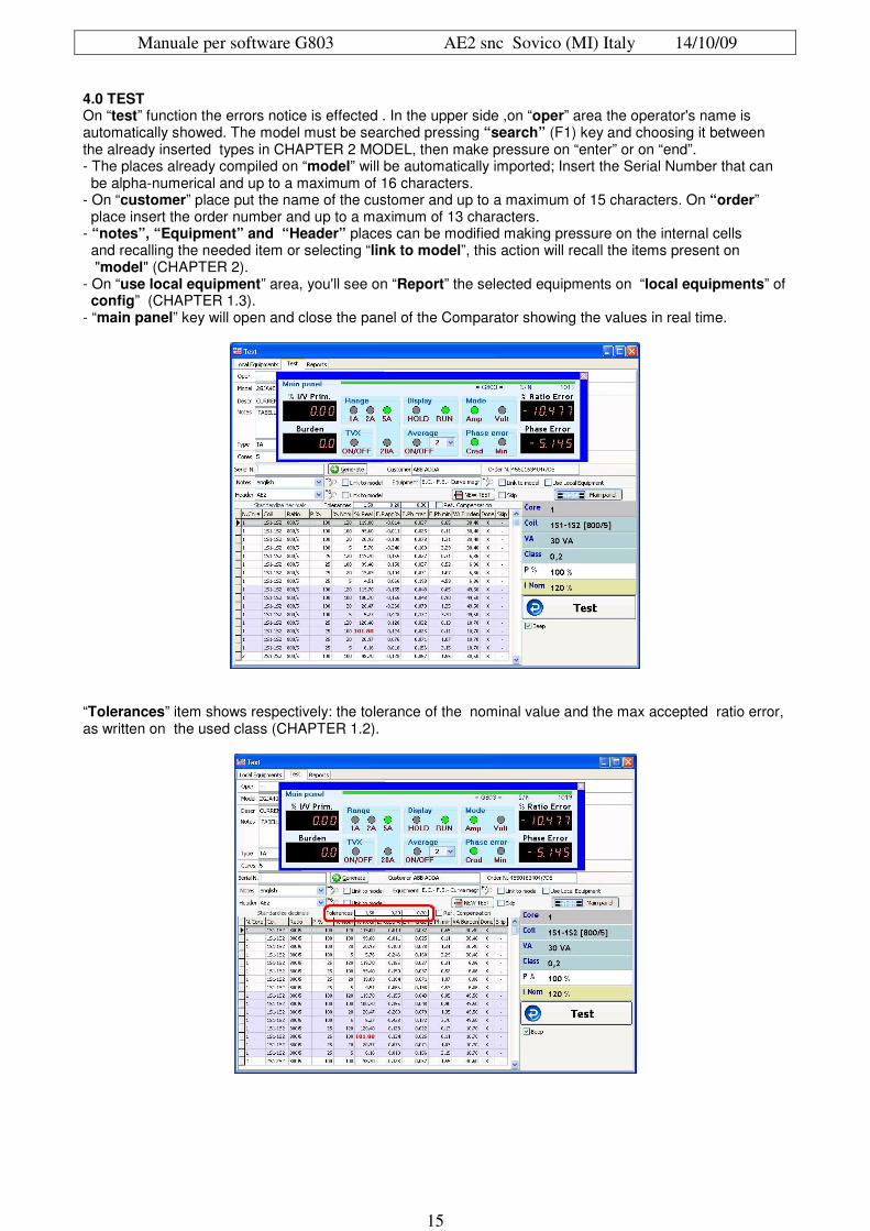
4.0 TEST On “test” function the errors notice is effected . In the upper side ,on “oper” area the operator's name is automatically showed. The model must be searched pressing “search” (F1) key and choosing it between the already inserted types in CHAPTER 2 MODEL, then make pressure on “enter” or on “end”. - The places already compiled on “model” will be automatically imported; Insert the Serial Number that can be alpha-numerical and up to a maximum of 16 characters. - On “customer” place put the name of the customer and up to a maximum of 15 characters. On “order” place insert the order number and up to a maximum of 13 characters. - “notes”, “Equipment” and “Header” places can be modified making pressure on the internal cells and recalling the needed item or selecting “link to model”, this action will recall the items present on "model" (CHAPTER 2). - On “use local equipment” area, you'll see on “Report” the selected equipments on “local equipments” of config” (CHAPTER 1.3). - “main panel” key will open and close the panel of the Comparator showing the values in real time.
“Tolerances” item shows respectively: the tolerance of the nominal value and the max accepted ratio error, as written on the used class (CHAPTER 1.2).

Manuale per software G803 AE2 snc Sovico (MI) Italy 14/10/09
16
“Ref. Compensation” area, introduces the correction curve if previously inserted in "model" and it will be immediately showed under the “main panel”.
Into the red place, on the left, the correction values with the correspondent plus or minus mark are showed, while on the right side the corrected values (algebraic sum). - Once all the necessary parameters are inserted, press “New test” key and all the tests to make will appear in the downer area.
Now, with Comparator connected to sample (Tac/Tvc) and testing transformers (TAx/TVx), reach the nominal value (example 120%) requested by the test; then press the “test” key (or enter key on keyboard), continue paying attention to change the VA values when requested (example: 25%), situated on the right table over the “test” key. - After the last measurement is effected the program advices that the test is completed, then make pressure on "OK" to confirm.

Manuale per software G803 AE2 snc Sovico (MI) Italy 14/10/09
17
To execute a new test, it is necessary to modify the Serial Number, to advance one number respect to the existing, make pressure on “generate” key then press “new Test” key. “Standardize decimals” key permits to conform the decimal values. - If “skip” place is selected (but the point is positioned on "YES" on the "config/classes”) the measurements will be not effected. - it is possible to add a sound message every time “Test” key is pressed, selecting beep”. NOTE: When you move from TEST to REPORTS, pay attention to select the test that you want to see on screen TEST when you want to come back. If in REPORTS you select a test, the same test will be visualized on TEST. 5.0 REPORT “Report” function permits to see, to modify and print all the effected tests. It is also possible to insert the composite error, the Safety Factor (Fs) and the magnetization curve. 5.1 Database
On the upper table, once the data of the effected tests were registered, making pressure only one time on the top of the column, it is possible to arrange them in sequence. The arrow near the name will help you to choose the increasing or decreasing sequence. Double pressure on the cell and on the head-line will filter the data with that particular content, another double pressure will take out the filter. - Above “serial N” and “Model” places there are two empty cells usable for the fast research (“fast search”) - “inside” square area (when selected) admits internal values to the sequence; for example if you put ”C” letter, the sequence "abc123" will be showed because in its internal the C letter is present; if “match case” is selected (it recognize the capital and small letter) the sequence will be not displayed because in its internal there is not the capital "C". - Columns “Done”, “Printed” and “Saved”, inform about the test status. On the lower place there are the noticed technical data, or the data to insert. - “Test Result” will show the results of the executed test with the comparator; under it “composite error” and “ Safety factor” permit to insert the composite error and the safety factor. “Magnetization curve” permits to insert the magnetization curve. - “Test equipments” shows the already equipments present on ”config” (see chapter 1.3). - “Show equipments’ sets” is displayed when “Modify Values” is marked only and permits to modify the inserted equipments. - “Standardize decimals” key (visible “Test results” only) uniform the decimals numbers of the same column. On the right side there are six items that ,when selected, as example:. show the correspondent item on final “Report”. - “Summary” shows the summary of the technical data. - “Show Equipment” adds to the “report” the equipments previously inserted. - “Show C.Error / SF” shows the data of composite error and/or safety factor. - “Print test last” if selected moves the Ratio Errors and Phase Errors after the “notes”. - “Show Mag.Curve” will shows the magnetization curve. - “Show Signatures” shows the signatures.

Manuale per software G803 AE2 snc Sovico (MI) Italy 14/10/09
18
Under the above six items there are four areas that permit to see, to save or print the “Report”. - “View Report” key shows the preview print. - “Print Report(s)” permits to print one or more tests. - “Save Report(s) PDF” exports the “Report” in PDF format (Adobe Acrobat Reader). - “Save Report(s) RTF” key exports the "Report" as text file RTF editable (this function can have some defects of the display). NOTE: to modify or to insert every parameter it is necessary to check the “Modify Values” cell. 5.2 Magnetization Curve
To insert the magnetization curve make pressure on the proper key “Magnetization Curve” after that put on the proper place under the column ”I (x)” the current value absorbed by the transformer, expressed in mA; closely to it, under the column “V (y)” put the correspondent voltage value expressed in Volt. - When a minimum quantity of three couple of values are inserted, the curve will appear on the proper place. On its right there are the formulation parameters: in the upper part two adjacent places named “Origin” can be used to modify the starting value of x and y axis; while the two external places named “Range” increase the final value of the mentioned axis. Under them you see two sliders necessary to modify the thickness (using “Size”) and the form (using “Smooth”) of the final curve. -By a double pressure on “Colour” place it is possible to change the colour of the curve 5.3 Safety Factor and Composite Error To insert the Safety factor and/or the Composite Error it is necessary to be in “Test results”, check “Modify values” then press the needed key “Safety Factor” and/or “Composite Error”. - In case “Composite Error” is pressed, it is necessary to have correctly written the class on “model” (see chapter 1.2). Select the test line on which it is necessary to insert the Safety Factor and/or the Composite Error, then make pressure under the “core” column , press the directional key toward the down side and automatically the correspondent data will appear. Insert the resistance value under the column “R meas” and the ambient temperature under the column “T amb °C”, under the column “R ct 75°C” the resistances value(at 75°C) will be automatically showed - On “Safety Factor” write the voltage value necessary in order to obtain the nominal absorbed current and the value automatically appear on the column “S.F.”. - Concerning C.E. it is necessary to measure the absorbed current (applying to the transformer terminals the voltage mentioned on column “V”) and write it on the proper area “I_meas”, on “Error %” place you'll see automatically the calculated Composite Error (%) value. NOTE: Safety Factor and Composite Error, can be inserted in every groups of tests effected with the same parameters (on “Reports” the different colours identify the different groups.
Manuale per software G803 AE2 snc Sovico (MI) Italy 14/10/09
19
6. GLOSSARY: Admin: (Administrator); with this code it is possible to work in absence of other posted operators. Allow change: Permits to change the data. Config: (Configuration); under this title there are the parameters to use. Database: Archive of organized data in order to easily search for the proper univocal contents. Local Equipments: Being usable in the net, more terminals, and consequently more equipments, can be connected; local equipments are the actually working. Report: This is the final report, printed or saved of all executed tests.