galaxie gv-per-meter accelerator and x- ray-source integrated experiment j. rosenzweig ucla dept. of...
TRANSCRIPT

GALAXIE GV-per-meter AcceLerator And
X-ray-source Integrated Experiment
J. RosenzweigUCLA Dept. of Physics and AstronomyBNL ATF User Meeting, April 26, 2012
The GALAXIE Collaboration
UCLA Dept. of Physics and Astronomy Miao, Musumeci, Putterman, Regan, Rosenzweig (PI)
Stanford Linear Accelerator Center Tantawi
Penn State University Jovanovic
RadiaBeam Technologies Murokh, Boucher
Brookhaven National Laboratory (w/o DARPA funds) Pogorelsky, Yakimenko

Answering the AXiS DARPA BAA
Compact, narrow-band, high flux X-ray source Utilize GV/m fields 0.1% BW, set by imaging apps (e.g. phase contrast)
Efficient: Energy conversion 10-4 Indicated in BAA Chooses FEL over ICS Sets FEL
Ultra-high brightness electron beams Pellegrini criterion on emittance Brightness for gain
Dielectric laser acceleration
Optical undulators (all optical system)
ICS illumination of “vespa” at BNL ATF
Advanced X-Ray integrated Sources (AXiS)

The X-ray FEL
LCLS: First hard X-ray FEL Based on existing linear
accelerate at SLAC Now working at 1.5 Å!
Many more worldwide UCLA performed POP expts.
Revolutionary capabilities Single molecule imaging Coulomb explosions Nonlinear QED
DARPA AXIS: apply to medical imaging Compact and inexpensive
E=14 GeVlr=1.5 Å
A. Murokh, et al., Phys. Rev. E 67, 066501 (2003)
courtesy G. Andonian
Saturation at VISA~800 nm

Coherence: the importance of the phase information
(a) (b)
Amplitude of (a) + phases of (b)
Amplitude of (b) + phases of (a)

UCLA core research strength:Advanced acceleration techniques High intensity electron/laser beam excites dielectric structures or
plasmas
GV/m to TV/m fields possible; scenario dependent
High energy densities: scaling of repetition rate difficult
Utilize resonant optical/IR structure acceleration Extend accelerator structure concept over 4 orders of magnitude in l
Married with advanced FEL: first “5th generation” light source Stepping stone to higher energy applications (e.g. linear collider)
>1 TVm accelerating fields in proposed LCLS PWFA experiment
J.B. Rosenzweig, A. Murokh, and C. Pellegrini, PRL 74, 2467 (1995)

All-optical FEL
Ultra-low emittance, optically gated electron source (magnetized beam)
Low b, relativistic photonic dielectric acceletors
Optical (or THz) undulator Long l laser source: 5 microns Challenging integrated project
GALAXIE: Compact, High-Brightness, Monochromatic X-rays from All-Optical, High Field Accelerators and Undulators
Traveling wave dielectric laser accelerator
Overmoded optical undulator
Photonic defect mode bi-harmonic structure with 2nd order focusingand acceleration on highspatial harmonic
200 MV/m X-band RF gun w/flat beam converter

Long-wavelength (5 mm) laser system
Avoid aperture limitations Vertical emittance @ 1E-9 m level for 5 mm
case (3E-11 m @0.8 mm) Spatial harmonic 2nd order focusing
More stable longitudinal acceleration (enlarged buckets) Complex dynamics from focusing spatial
harmonic
Mitigate breakdown Small quantum energy Optimize at ~ps pulse length
Breakdown thresholds unknown (>GV/m?) Material investigations needed
Biharmonic photonic modedielectric structure
Longitudinal phase space (Poincare)

The Accelerator Structure: Bigger Picture
Proposed silicon structure
Coupling dynamics
Monolithic plasma-etched Si assembly

5 mm Laser Approach

Mid-IR seed source setup
Palitra also at UCLA

First Light at 5 mm
But we need high power for materials testing now…

Optical properties, breakdown at 5 mm
Limited data exists on 5 mm light interactions Index, loss tangent, breakdown Long pulses more often studied.
For <10 ps pulses, electrons react faster than lattice Avalanche ionization dominant
Single shot vs. high rep, fluence threshold
Study critical for: Structure (accelerator and fabrication Optical components: pulse, color splitters
Candidate material crystals in hand CaF2,MgF2,ZnSe,Ge,Si,Al2O3
Testing ongoing at BNL ATF

Diagnostic layout: Initial BNL tests
HeNe Sample
CO2 Laser
HeNeDet - Fast
HeNeDet - Fast
50/50
HeNe Lens
CO2 OAPw/ Hole
Cal.
Reference Det.
Co2 Spt.
Cal.
Cal.
CaF2
Atten.I
tEvent
Red – He-NeGreen – 10.2 um CO2Purple – 5.1 um light
Doubling crystals ordered, receiv (Altos Photonics/EKSMA)ZGP and AgGaSe2
Joint project: UCLA, RadiaBeam, BNL
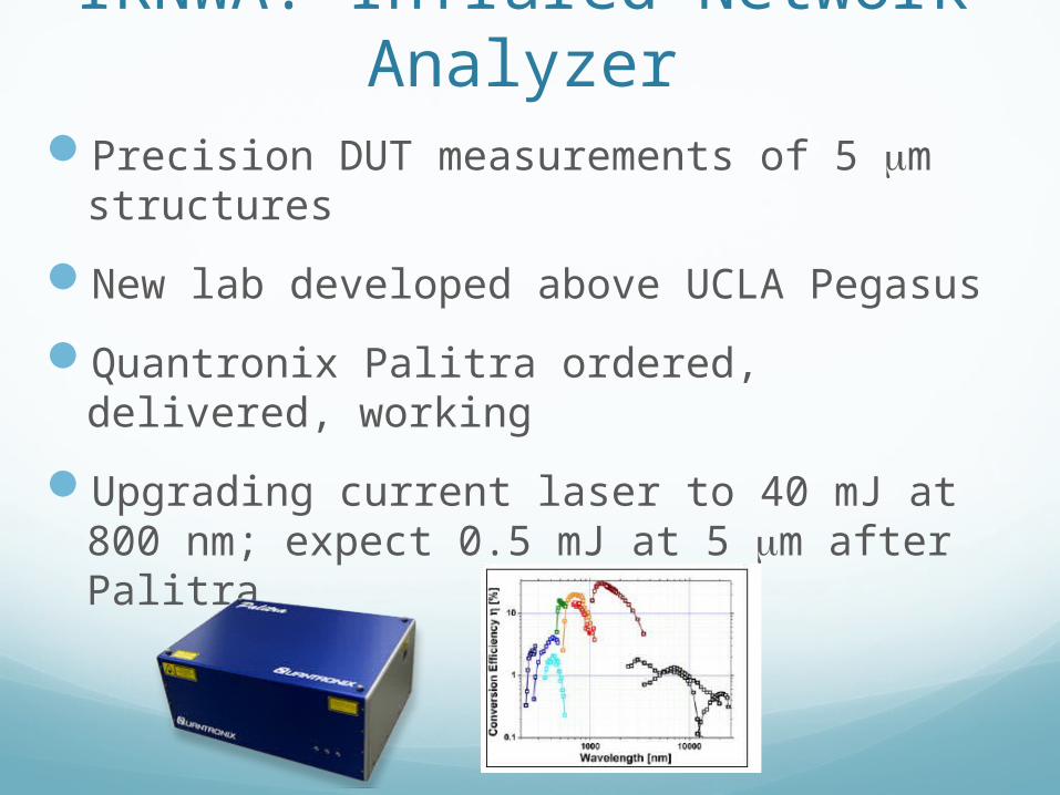
IRNWA: Infrared Network Analyzer
Precision DUT measurements of 5 mm structures
New lab developed above UCLA Pegasus
Quantronix Palitra ordered, delivered, working
Upgrading current laser to 40 mJ at 800 nm; expect 0.5 mJ at 5 mm after Palitra

Wakefields: 1st observation of slab structure at BNL ATF
• Coherent Cerenkov radiation benchmark on mode frequencies
• Deceleration/acceleration observed
• Start-to-end simulations w/OOPIC– Now extended to VORPAL 3D
• Under review at PRL • Continuation of work at SLAC
FACET
CCR signal and FFT
Observed (solid) and simulated(dashed) momentum spectra
x (m)
z (m)

Next step: photonic structures
Bragg, GALAXIE, woodpile structuresBoth ATF and FACET planned
Convergent with HEP programAdvantage in fabrication at THz
Narrow, wide defectsOptimized and Cowan-style, any axis…
Defect with optimized symmetry

1st VORPAL simulations
x
y beam
DIMENSIONs:Diameter of cylindrical:125 umBeam Channel: 250umA=350um C=500um
a
First version: quartz tubes…More from Gerard Andonian presentation
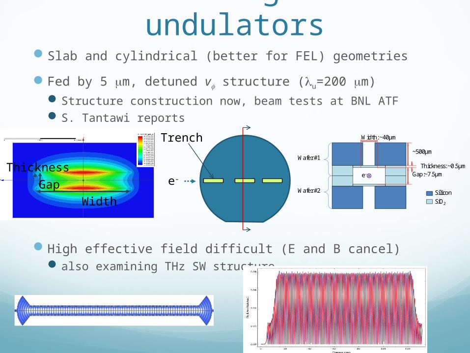
Electromagnetic undulators
Slab and cylindrical (better for FEL) geometries
Fed by 5 mm, detuned vf structure (lu=200 mm) Structure construction now, beam tests at BNL ATF S. Tantawi reports
High effective field difficult (E and B cancel) also examining THz SW structure
GapThickness
Width
e-
Trench
e-
SiliconSiO2
~500µm
Gap:~7.5µmThickness: ~0.5µm
Width: ~40µm
Wafer #1
Wafer #2

Alternative: laser cut-PM undulator
3D nonlinear FEM using periodic BCs to simulate infinite array(checked with RADIA at UCLA)
Collaboration with Arnold group (Florida)
lu: 400 µm, B0=0.34 T
Magnet width: 200 µm Magnet gap: 200 µm Undulator length: 2 cm Material: laser cut NdFeB
Experiments planned at BNL- Initial testing at UCLA - Same setup as slab wakes - 150 eV photon production
- F. O’Shea reports
Potential high impact on standard light sources
ConclusionsGALAXIE provides new impetus to UCLA-
centered collaborative work at ATF5 um materials testingPhotonic/slab structure wakesEM undulator PM microundulator
Overview complemented by more detailed presentations
Materials/undulator proposal under development Issued after DARPA mid-year review (May 9-10)