gamespace/ truespace torque dts exporter documentation
TRANSCRIPT

GameSpace/ TrueSpaceTorque DTS Exporter Documentation

Setting Up Your Object For Export . . . . . . . . . . . . . . . . . . . . . . 3Object Orientation . . . . . . . . . . . . . . . . . . . . . . . . . . . . . . . . . . 3Working With Layers . . . . . . . . . . . . . . . . . . . . . . . . . . . . . . . . 3
Configuring Torque Material Properties . . . . . . . . . . . . . . . . . . 4Torque Material Property Settings . . . . . . . . . . . . . . . . . . . . . . 4
Using The Features Of The DTS Format. . . . . . . . . . . . . . . . . . 5The Bounds Object . . . . . . . . . . . . . . . . . . . . . . . . . . . . . . . . . 5Ground Transform . . . . . . . . . . . . . . . . . . . . . . . . . . . . . . . . . . 5Mipmap Control . . . . . . . . . . . . . . . . . . . . . . . . . . . . . . . . . . . . 5Level Of Detail . . . . . . . . . . . . . . . . . . . . . . . . . . . . . . . . . . . . . 6Auto Level Of Detail. . . . . . . . . . . . . . . . . . . . . . . . . . . . . . . . . 6Collision Objects . . . . . . . . . . . . . . . . . . . . . . . . . . . . . . . . . . . 7Line Of Sight Collision Objects . . . . . . . . . . . . . . . . . . . . . . . . 8Named Nodes . . . . . . . . . . . . . . . . . . . . . . . . . . . . . . . . . . . . . 9Bilboards . . . . . . . . . . . . . . . . . . . . . . . . . . . . . . . . . . . . . . . . 11Bilboard Details . . . . . . . . . . . . . . . . . . . . . . . . . . . . . . . . . . . 11Miscellaneous Layer Flags . . . . . . . . . . . . . . . . . . . . . . . . . . 11
Animation . . . . . . . . . . . . . . . . . . . . . . . . . . . . . . . . . . . . . . . . . 12Supported Animation Types. . . . . . . . . . . . . . . . . . . . . . . . . . 12Future Animation Support . . . . . . . . . . . . . . . . . . . . . . . . . . . 12Using Clips For Animation Export . . . . . . . . . . . . . . . . . . . . . 12Clip Properties. . . . . . . . . . . . . . . . . . . . . . . . . . . . . . . . . . . . 12Clip Flags . . . . . . . . . . . . . . . . . . . . . . . . . . . . . . . . . . . . . . . 12Exporting Animation . . . . . . . . . . . . . . . . . . . . . . . . . . . . . . . 13DSQ Export . . . . . . . . . . . . . . . . . . . . . . . . . . . . . . . . . . . . . . 13
Configuration Data . . . . . . . . . . . . . . . . . . . . . . . . . . . . . . . . . . 13
Triggers . . . . . . . . . . . . . . . . . . . . . . . . . . . . . . . . . . . . . . . . . . . 13
GameSpace / TrueSpace - Torque DTS Exporter Documentation2
Table Of Contents
Much of the basic DTS feature documentation in this file was assembled in part from other tutorials and docs created by various members of the Garage Games Community, most notably Logan Foster & Joe Maruschak and thanks to Tim Gift and Clark Fagot for their help along the way. Also, special thanks to Stan Melax and the beta testers who weren’t afraid our software would erase their hard drives.

Configuring DTS Material Properties
GameSpace / TrueSpace - Torque DTS Exporter Documentation4
GameSpace / TrueSpace - Torque DTS Exporter Documentation3
Object OrientationProper object orientation of your DTS object is created by using the default view positions of GameSpace. Positive Y is forward, and Z is up.
Working With LayersThis exporter is heavily reliant on the use of layers to configure the various settings and options you can employ to create your DTS object.
The layers tool bar is located on the top left hand side of the GameSpace screen. You can add new layers to your scene by clicking the “add layer” button at the bottom of the layers tool bar. You can also Show, Lock and Hide all of the objects on any given layer by holding down the left mouse button over one of the layer icons and selecting the desired option from the flyout menu.
Right clicking on the “add layer” button will open the layer information dialog box. From here you can select any layer in your scene and rename it to activate several features of this DTS exporter.
Right clicking on the object tool will open the Object Inspection. From here you can also rename layers and move the objects in your scene from layer to layer.
Each layer in your scene represents a detail level of your exported DTS object.
Top
Front Left
Add Layer
Sh
ow
Lo
ck
Hid
e
Object Tool
Detail 2: size=80, autoLOD=90
Detail 2: size=80, au
Object Inspector
Layer Information
Material Shader Setupload a texture shader.load plain transparency and set the trans value to 1load a environment map shader.load your texture into the texture map shader.In your environment map shader use these settings1. Set luminance to 02. Set diffusion to max3. Set shininess to 04. Set specular to 0
This will create a neutral texture only setup for the DTS export. Leaving the color shader as a solid color will create a DTS without materials.
DTS Material Properties
Self IlluminationSet Luminance to anything > 0 ;Self Illuminate is turned on
Material TransparencySet Transparency < 1 ; Transparency is turned onTransparency is based off of the texture map alpha channel (must use png)
Subtractive TransparencyTurn on transparencySet specular > 0 but < 1 ; Then Subtractive is onTransparency is based off of the texture map alpha channel (must use png)
Additive TransparencyTurn on transparencySet specular = 1(max) Then Additive is turned onTransparency is based off of the texture map alpha channel (must use png)
Environment MappingSet reflection > 0 ; Then Reflection is turned on
Reflectivity is based off of the alpha channel of texture loaded into the environment map shader(must use png)
Transparency
Environment Map
Note: This exporter supports the use multiple textures on your DTS object. Per face or per distinct object. In game performance issues can arise depending on the size and number of textures on your object.
Setting up your object for export

GameSpace / TrueSpace - Torque DTS Exporter Documentation5
Using The Features Of The DTS Format
GameSpace / TrueSpace - Torque DTS Exporter Documentation6
Using LayersLayers are used to control how geometry is exported to your DTS file. Any object that is not placed on a layer is ignored by the exporter.
Layer should be renamed from their default number to a more descriptive name.
Examples: “Mesh Layer” or “Vehicle Body”
A colon should follow the name of a layer, followed by comma separated flag names as required:
Layer naming convention:“Layer name: flag, flag, etc..."
Level Of DetailLevel of Detail Layers are used to store high and low polygon versions of your DTS object. The size value tells the Torque engine when to switch from one detail level to another. This is used to reduce the amount of geometry on screen as objects move further away from the camera.
You can manually create detail levels by creating a new layer and adding size flag to its name. On this layer you can place a mesh with less detail than your primary mesh.
size=xxxWhere xxx = detail level size.This is used for detail level layers.
Example Use: “Detail Level 1: size=20”
Auto Level Of DetailUsing the autoLOD flag in combination with the size flag will allow the exporter to automatically generate detail level meshes for your model.
autoLOD=xxxWhere xxx = polygon reduction.This is used for automated detail level layers.
Example Use: “Detail1: size=80, autoLOD=80”
The number is based of 100% so in this example 80 = 20% polygon reduction.
When using LOD your highest detail level ( Your primary object mesh ) must also have a size flag.
Mipmap Control Flags:By default, textures are mipmapped but you can add flags to the bounds layer to change how or if mipmaps are generated.
no_mipmapdo not generate mipmaps for any textures
no_mipmap_transIf you want most textures to mipmap, but not translucent textures
no_black_borderTranslucent textures that do not tile are considered"zeroborder" textures -- that is, we assume thatthere is a blackborder around the texture and we enforce this in the mipmap. This is normally what one wants, because otherwise streaks occur when off-tile parts of the face are drawn. If you don't want to do this to your non-tiling translucent textures, then you can turn it off using this flag.
Ground Transform (not exported yet)
Animation sequences that move the character must have ground transform. The engine knows that the character has a specific velocity in all directions (this is set in script).
Ground transform is based on the animation of the bounding box. If you want to export a running person, you would place the bounding box around the person at time 0, with the origin of the box at the persons feet. As the person runs, you would animate the bounding box to keep pace with the person.
If you have no ground transform, the animation will not play when the character moves.
770 Triangles
1100 Triangles
2200 Triangles
Layer Name:Mesh Layer: size=145
Original Mesh Layerno autoLOD flag
Layer Name:Detail1: size=80, autoLOD=50
Auto Generated Mesh50% Triangle Reduction
AutoLOD Example Usage
Layer Name:Detail2: size=20, autoLOD=35
Auto Generate Mesh65% Triangle Reduction
Detail 2: size=80, autoLOD=90
Layer Name
The Bounds ObjectThe DTS format requires a bounds object that surrounds your DTS object. You can optionally add a custom box this layer to be used as the bounds object. The size of the bounds object is calculated automatically if no object is found on the bounds layer.
The orientation of the bounding box defines the orientation of the object. When you create the bounds, you are creating a mini world that defines how the object will orient itself in the Torque Engine
Useage: add a layer named “bounds:”
Using The Features Of The DTS Format

GameSpace / TrueSpace - Torque DTS Exporter Documentation7
GameSpace / TrueSpace - Torque DTS Exporter Documentation8
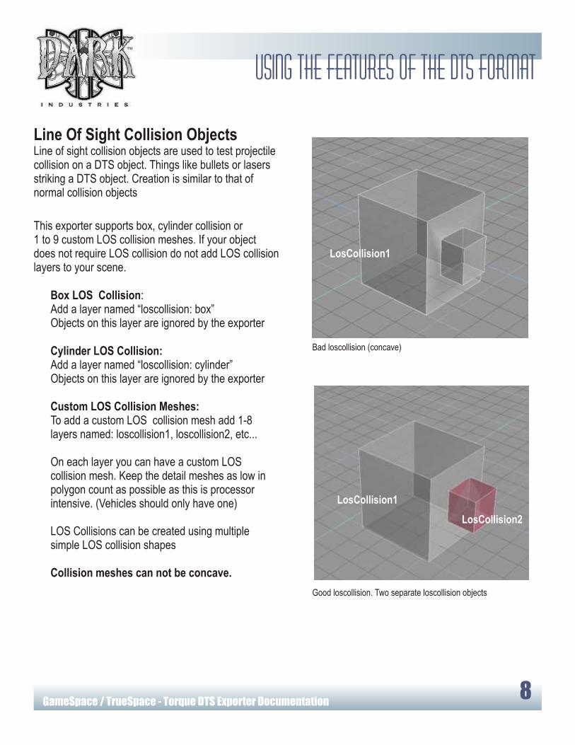
Line Of Sight Collision ObjectsLine of sight collision objects are used to test projectile collision on a DTS object. Things like bullets or lasers striking a DTS object. Creation is similar to that of normal collision objects
This exporter supports box, cylinder collision or1 to 9 custom LOS collision meshes. If your object does not require LOS collision do not add LOS collision layers to your scene.
Box LOS Collision:Add a layer named “loscollision: box”Objects on this layer are ignored by the exporter
Cylinder LOS Collision:Add a layer named “loscollision: cylinder”Objects on this layer are ignored by the exporter
Custom LOS Collision Meshes:To add a custom LOS collision mesh add 1-8 layers named: loscollision1, loscollision2, etc...
On each layer you can have a custom LOS collision mesh. Keep the detail meshes as low in polygon count as possible as this is processor intensive. (Vehicles should only have one)
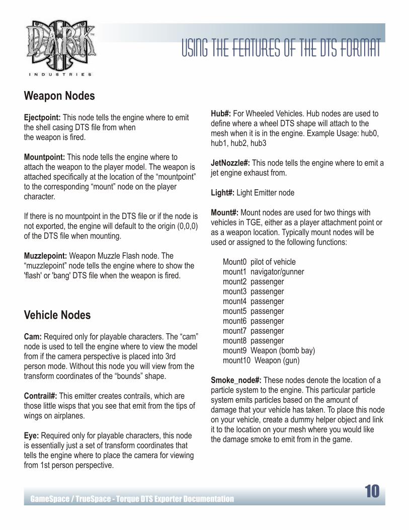
LOS Collisions can be created using multiple simple LOS collision shapes
Collision meshes can not be concave.
Collision ObjectsCollision meshes are used to perform collision tests within the Torque Game Engine. Collision objects should be very simple shapes and can not be concave (They can not indent or push into them at any location)
This exporter supports box, cylinder collision or1 to 9 custom collision meshes. If your object does not require collision do not add collision layers to your scene.
Box Collision:Add a layer named “collision: box”Objects on this layer are ignored by the exporter
Cylinder Collision:Add a layer named “collision: cylinder”Objects on this layer are ignored by the exporter
Custom Collision Meshes:To add a custom collision mesh add 1-8 layers named collision1, collision2, etc...
On each layer you can have a custom collision mesh. Vehicles are limited to ONE collision mesh for the collision shape.
Complex collisions can be created using multiple simple collision shapes
Collision meshes can not be concave.
Bad collision (concave)
Good collision. Two separate collision objects
Collision1
Collision2
Collision1
Bad loscollision (concave)
Good loscollision. Two separate loscollision objects
LosCollision1
LosCollision2
LosCollision1
Using The Features Of The DTS FormatUsing The Features Of The DTS Format
GameSpace / TrueSpace - Torque DTS Exporter Documentation7
GameSpace / TrueSpace - Torque DTS Exporter Documentation8
Line Of Sight Collision ObjectsLine of sight collision objects are used to test projectile collision on a DTS object. Things like bullets or lasers striking a DTS object. Creation is similar to that of normal collision objects
This exporter supports box, cylinder collision or1 to 9 custom LOS collision meshes. If your object does not require LOS collision do not add LOS collision layers to your scene.
Box LOS Collision:Add a layer named “loscollision: box”Objects on this layer are ignored by the exporter
Cylinder LOS Collision:Add a layer named “loscollision: cylinder”Objects on this layer are ignored by the exporter
Custom LOS Collision Meshes:To add a custom LOS collision mesh add 1-8 layers named: loscollision1, loscollision2, etc...
On each layer you can have a custom LOS collision mesh. Keep the detail meshes as low in polygon count as possible as this is processor intensive. (Vehicles should only have one)
LOS Collisions can be created using multiple simple LOS collision shapes
Collision meshes can not be concave.
Collision ObjectsCollision meshes are used to perform collision tests within the Torque Game Engine. Collision objects should be very simple shapes and can not be concave (They can not indent or push into them at any location)
This exporter supports box, cylinder collision or1 to 9 custom collision meshes. If your object does not require collision do not add collision layers to your scene.
Box Collision:Add a layer named “collision: box”Objects on this layer are ignored by the exporter
Cylinder Collision:Add a layer named “collision: cylinder”Objects on this layer are ignored by the exporter
Custom Collision Meshes:To add a custom collision mesh add 1-8 layers named collision1, collision2, etc...
On each layer you can have a custom collision mesh. Vehicles are limited to ONE collision mesh for the collision shape.
Complex collisions can be created using multiple simple collision shapes
Collision meshes can not be concave.
Bad collision (concave)
Good collision. Two separate collision objects
Collision1
Collision2
Collision1
Bad loscollision (concave)
Good loscollision. Two separate loscollision objects
LosCollision1
LosCollision2
LosCollision1
Using The Features Of The DTS FormatUsing The Features Of The DTS Format

GameSpace / TrueSpace - Torque DTS Exporter Documentation9
GameSpace / TrueSpace - Torque DTS Exporter Documentation10
Weapon Nodes
Ejectpoint: This node tells the engine where to emit the shell casing DTS file from whenthe weapon is fired.
Mountpoint: This node tells the engine where to attach the weapon to the player model. The weapon is attached specifically at the location of the “mountpoint” to the corresponding “mount” node on the player character.
If there is no mountpoint in the DTS file or if the node is not exported, the engine will default to the origin (0,0,0) of the DTS file when mounting.
Muzzlepoint: Weapon Muzzle Flash node. The “muzzlepoint” node tells the engine where to show the 'flash' or 'bang' DTS file when the weapon is fired.
Vehicle Nodes
Cam: Required only for playable characters. The “cam” node is used to tell the engine where to view the model from if the camera perspective is placed into 3rd person mode. Without this node you will view from the transform coordinates of the “bounds” shape.
Contrail#: This emitter creates contrails, which are those little wisps that you see that emit from the tips of wings on airplanes.
Eye: Required only for playable characters, this node is essentially just a set of transform coordinates that tells the engine where to place the camera for viewing from 1st person perspective.
Named NodesNamed nodes are used to support special features of the Torque Engine. In order for Players, weapons and vehicles to function properly certain nodes must exist on a layer named “Nodes”.
Left clicking on the DTS exporter icon will open the exporter dialog box. From here either type a node name into the or choose one from the drop down list and click “Add Node”. If the node layer does not exist the exporter will add the layer for you.
Nodes are created with 0,0,0 rotation and are oriented in the default view. It is sometimes helpful to view scene through a node to make sure the node is oriented properly. You can resize nodes as you wish only placement and orientation are important.
The colored face of the node indicates the direction the node is currently facing.
Character & Static Object Nodes
Cam: Required only for playable characters. The “cam” node is used to tell the engine where to view the model from if the camera perspective is placed into 3rd person mode. Without this node you will view from the transform coordinates of the “bounds” shape.
Eye: Required only for playable characters, this node is essentially just a set of transform coordinates that tells the engine where to place the camera for viewing from 1st person perspective.
Light#: Light Emitter node
Mount#: Mount nodes are used to tell the engine that something can be attached to your model at this position. For example you would use a mount node to tell the engine where to place a weapon on your player model.
Ski#: Ski Marker node
Hub#: For Wheeled Vehicles. Hub nodes are used to define where a wheel DTS shape will attach to the mesh when it is in the engine. Example Usage: hub0, hub1, hub2, hub3
JetNozzle#: This node tells the engine where to emit a jet engine exhaust from.
Light#: Light Emitter node
Mount#: Mount nodes are used for two things with vehicles in TGE, either as a player attachment point or as a weapon location. Typically mount nodes will be used or assigned to the following functions:
Mount0 pilot of vehiclemount1 navigator/gunnermount2 passengermount3 passengermount4 passengermount5 passengermount6 passengermount7 passengermount8 passengermount9 Weapon (bomb bay)mount10 Weapon (gun)
Smoke_node#: These nodes denote the location of a particle system to the engine. This particular particle system emits particles based on the amount of damage that your vehicle has taken. To place this node on your vehicle, create a dummy helper object and link it to the location on your mesh where you would like the damage smoke to emit from in the game.
Cam
Eye
Add node buttonNode Selector
Using The Features Of The DTS Format Using The Features Of The DTS Format

GameSpace / TrueSpace - Torque DTS Exporter Documentation11
GameSpace / TrueSpace - Torque DTS Exporter Documentation12
Exporting animation
BillboardsBillboard are objects (usually 2d) that always face the player. For example, you could have an explosion in which shrapnel flies out from the center and also have little explosion balls fly out that are just flat polygons that always face you.
Adding the billboard or billboardz flag to a layer name will cause the exported object(s) on that layer to always face the player.
billboardTells the exporter that the object(s) on this layer always face the player
Example Use: “Mesh Layer: billboard”
billboardzTells the exporter that objects on this layer always face the player on their Z axes
Example Use: “Mesh Layer2: billboardz”
Billboard Detail LevelsThe billboard layer flag and the size flag can be used in combination to create billboard detail levels.
This will create a detail level composed of two or more triangles that will always face the camera.
Example Use: “Detail6: size=12, billboard”
Supported Animation TypesTransform Animation: Often referred to as skeletal animation or node animation, this type of animation is created by building a skeleton for your model and animating it using key frames stored clips.
Future Animation SupportTexture animation: Enables animation of Texture Coordinates. This is useful for things where the texture itself must animate. Scrolling computer monitors, waterfalls, and tank treads are just a few of the applications for animated texture coordinates.
IFL animation: Allows you to export Image File Lists. These are a sequence of image files, and are useful for things like explosions
Visibility Animation: Use of animated object transparency.
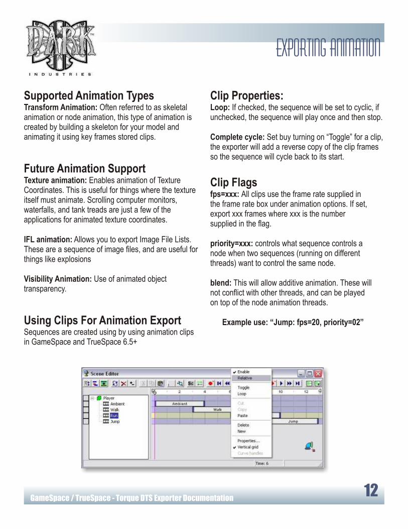
Using Clips For Animation ExportSequences are created using by using animation clips in GameSpace and TrueSpace 6.5+
Miscellaneous Layer FlagsNamed nodes are used to support special features of the Torque Engine. In order for Players, weapons and vehicles to function properly certain nodes must exist on a layer named “Nodes”.
SortTells the exporter to sort the mesh on this layer for proper display of objects with transparency.
Example Use: “Mesh Layer: sort”
no_stripTells the exporter not to use tri-stripping for the objects on this layer.
Example Use: “Mesh Layer: no_strip”
enormalsEmcode normals
Example Use: “Mesh Layer: enormals”
Clip Properties:Loop: If checked, the sequence will be set to cyclic, if unchecked, the sequence will play once and then stop.
Complete cycle: Set buy turning on “Toggle” for a clip, the exporter will add a reverse copy of the clip frames so the sequence will cycle back to its start.
Clip Flagsfps=xxx: All clips use the frame rate supplied in the frame rate box under animation options. If set, export xxx frames where xxx is the number supplied in the flag.
priority=xxx: controls what sequence controls a node when two sequences (running on different threads) want to control the same node.
blend: This will allow additive animation. These will not conflict with other threads, and can be played on top of the node animation threads.
Example use: “Jump: fps=20, priority=02”
Billboard
Using The Features Of The DTS Format
GameSpace / TrueSpace - Torque DTS Exporter Documentation11
GameSpace / TrueSpace - Torque DTS Exporter Documentation12
Exporting animation
BillboardsBillboard are objects (usually 2d) that always face the player. For example, you could have an explosion in which shrapnel flies out from the center and also have little explosion balls fly out that are just flat polygons that always face you.
Adding the billboard or billboardz flag to a layer name will cause the exported object(s) on that layer to always face the player.
billboardTells the exporter that the object(s) on this layer always face the player
Example Use: “Mesh Layer: billboard”
billboardzTells the exporter that objects on this layer always face the player on their Z axes
Example Use: “Mesh Layer2: billboardz”
Billboard Detail LevelsThe billboard layer flag and the size flag can be used in combination to create billboard detail levels.
This will create a detail level composed of two or more triangles that will always face the camera.
Example Use: “Detail6: size=12, billboard”
Supported Animation TypesTransform Animation: Often referred to as skeletal animation or node animation, this type of animation is created by building a skeleton for your model and animating it using key frames stored clips.
Future Animation SupportTexture animation: Enables animation of Texture Coordinates. This is useful for things where the texture itself must animate. Scrolling computer monitors, waterfalls, and tank treads are just a few of the applications for animated texture coordinates.
IFL animation: Allows you to export Image File Lists. These are a sequence of image files, and are useful for things like explosions
Visibility Animation: Use of animated object transparency.
Using Clips For Animation ExportSequences are created using by using animation clips in GameSpace and TrueSpace 6.5+
Miscellaneous Layer FlagsNamed nodes are used to support special features of the Torque Engine. In order for Players, weapons and vehicles to function properly certain nodes must exist on a layer named “Nodes”.
SortTells the exporter to sort the mesh on this layer for proper display of objects with transparency.
Example Use: “Mesh Layer: sort”
no_stripTells the exporter not to use tri-stripping for the objects on this layer.
Example Use: “Mesh Layer: no_strip”
enormalsEmcode normals
Example Use: “Mesh Layer: enormals”
Clip Properties:Loop: If checked, the sequence will be set to cyclic, if unchecked, the sequence will play once and then stop.
Complete cycle: Set buy turning on “Toggle” for a clip, the exporter will add a reverse copy of the clip frames so the sequence will cycle back to its start.
Clip Flagsfps=xxx: All clips use the frame rate supplied in the frame rate box under animation options. If set, export xxx frames where xxx is the number supplied in the flag.
priority=xxx: controls what sequence controls a node when two sequences (running on different threads) want to control the same node.
blend: This will allow additive animation. These will not conflict with other threads, and can be played on top of the node animation threads.
Example use: “Jump: fps=20, priority=02”
Billboard
Using The Features Of The DTS Format

GameSpace / TrueSpace - Torque DTS Exporter Documentation13
Exporting animation
Exporting AnimationTo export animation for your DTS object, left click the exporter icon to open the exporter dialog box. Then click the “export animation” check box and choose between the named animation clips in your scene in the DTS shape or as separate DSQ files. Then click the export button to export your DTS and animation
DSQ ExportExporting DSQ files exports the animation seperately from the DTS file. Each named animation clip in your scene is exported as a separate DSQ file using the clip name as the file name.
Configuration Data (not supported yet) There are a number of parameters used by the exporter that are read from the object notes.
By default, all transform animation in a shape during a sequence is exported. If a node differs from the default position in a sequence then the transform on that node is considered animated even if it is unchanging throughout the sequence.
The default position for all nodes is determined by the node position at frame 0 in your scene. Commands are used to determine which nodes are being exported to a particular thread, force export needed nodes, manually cull out useless nodes (or ones with potential conflicts) and otherwise take steps to ensure that threads do not fight for control of the same nodes.
Triggers (not supported yet)You can have up to 32 triggers (1-32) which are turned on using the configuration data stored in the object notes of your scene.
As an example, the easiest way to deal with footsteps is to have one trigger for each foot (1=left, 2=right, say). You may have an application where you want to know when the foot is supposed to be on the ground. In that case you would turn on the "foot on ground" state when it first contacts the ground and turn it off when the foot leaves. Thus each foot would have 2 trigger keys: a + one when the foot hits the ground and a - one when it leaves.
If you want your character to leave footprints, all you have to do is go to the trigger track of the appropriate sequence and add a trigger key and a value. In the default Torque engine,1 = left foot, 2 = right foot.
DTS Exporter Dialog Box