garlock expansion joints...garlock expansion joints offer superior performance, reliability and...
TRANSCRIPT

Leaders in Sealing Integrity
Garlock Expansion JointsTechnical Manual
PROUDLYMADE IN THE
USA

CONTENTS
Materials ..................................................................................3
PIPINGStyles 204, Narrow Arch ...........................................................6Style 206 EZ-FLO® ....................................................................8Styles 214, 215 .......................................................................10 GARFLEX® 8100 .....................................................................12Style 7250 FLEXO-MATIC® .....................................................13
LOW PRESSURE/DUCTINGStyle 9394 ...............................................................................14Style 8400 ...............................................................................15Style 8420 Split .......................................................................16
Customization Capabilities ..................................................17
Expansion Joint Accessories ...............................................18
Garlock expansion joints offer superior performance, reliability and service life. This in turn improves plant safety, increases the mechanical integrity of equipment and allows customers to gain a competitive advantage in the market place.
Industry Specific ............................................................... 19
Types of Expansion Joints ............................................... 20
Types of Pipe Movement ................................................. 21
Typical Properties of Elastomers .................................... 22
Installation ........................................................................ 23
Troubleshooting ............................................................... 24
General Precautions ......................................................... 24
Expansion Joint Weights ................................................. 25
Application Data Form ..................................................... 26
Drilling Charts ................................................................... 27
Spring Rate Tables ........................................................... 30
Survey Data Form ............................................................. 35
Garlock Fluid Sealing Products Technical Manual
IntroductionAn expansion joint is a specially engineered product inserted in a rigid piping system to achieve one or more of the following:
» Absorb movement » Relieve system strain due to thermal change, load stress, pumping
surges, wear or settling » Reduce mechanical noise » Compensate for misalignment » Eliminate electrolysis between dissimilar metals
At Garlock, the range of our engineering emphasis extends from the selection of the fabric used for reinforcement to the choice of materials used in actual expansion joint construction.
Rigid laboratory and field tests of our products support Garlock's assurances of long life and reliable service. In line with our commitment to safety, Garlock expansion joints' pressure and movement safety ratings exceed product specifications.
Garlock non-metallic expansion joints and flexible couplings are ideally suited for hundreds of applications in a wide range of industries including:
Joint SelectionTo select the proper expansion joint, consider:
» Pipe size » Pumped medium: the type of liquid, gas, or vapor in system » Temperature range » Pressure/vacuum range » Movements needed » Environment: degree of exposure to:
› Weathering › Oil › Sunlight › Open flame › Liquids › Chemicals › Gases › Other › Vapors » Installed face-to-face dimension(s) » Degree of pipe misalignment » Drilling: if other than standard 125Ib. ANSI, determine:
› Flange O.D. › Bolt circle › Number of bolt holes › Diameter of hole » Need for retaining rings » Need for control units
› Recommended for use with most expansion joints › Must be used in cases of insufficient pipe support » Need for special construction
GARLOCK RECOMMENDATIONS
204 206 214/215 8100 7250 9394 8400 8420 Split
Suction/Vacuum • •Discharge/Pressure • • •High Pressure/Piping • • • • •
Air Handling/Low Pressure/Ducting • • •
General Service • •Vibration/Noise Dampening • • • • • •
» Power generating » Pulp and paper » Chemical » Waste water and sewage
disposal » Marine
» Heating, ventilating and air conditioning
» Food and Beverage » Oil and Gas » Petrochemical » Mining
Garlock Fluid Sealing Products Technical Manual
Leaders in Sealing Integrity
3
Tube and Cover Materials
ABRA-LINE®
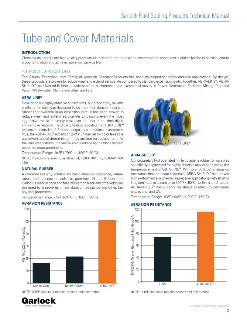
Developed for highly abrasive applications, our proprietary, millable urethane formula was designed to be the most abrasion resistant rubber liner available in an expansion joint. It has been proven to reduce wear and extend service life by causing even the most aggressive media to simply slide over the liner rather than dig in and remove material. Third party testing revealed that ABRA-LINE®
expansion joints last 2-3 times longer than traditional elastomers. Plus, the ABRA-LINE® expansion joints’ unique yellow color takes the guesswork out of determining if they are due for replacement. As the liner wears down, the yellow color darkens as the black backing becomes more prominent.
Temperature Range: -94°F (-70°C) to 180°F (80°C)
NOTE: Previously referred to as Style 404, 404HP, 404EPS, 404MAX, 406, 4394
NATURAL RUBBERA common industry solution for basic abrasion resistance, natural rubber is often seen in a soft, tan, gum form. Natural Rubber from Garlock is black in color and features carbon black and other additives designed to improve its innate abrasion resistance and other, key physical properties.
Temperature Range: -75°F (-24°C) to 180°F (80°C)
120
100
80
60
40
20
0Natural Gum Natural Rubber ABRA-LINE®
INTRODUCTION Choosing an appropriate high quality premium elastomer for the media and environmental conditions is critical for the expansion joint to properly function and achieve maximum service life.
ABRASION RESISTANCE ABRASION RESISTANCE
EPDM ABRA-SHIELD™
120
100
80
60
40
20
0
NOTE: 180°F and under material options and test method NOTE: 300°F and under material options and test method
ABRASIVE APPLICATIONSThe Garlock Expansion Joint Family of Abrasion Resistant Products has been developed for highly abrasive applications. By design, these products are proven to reduce wear and extend service life compared to standard expansion joints. Together, ABRA-LINE®, ABRA-SHIELD™, and Natural Rubber provide superior performance and exceptional quality in Power Generation, Fertilizer, Mining, Pulp and Paper, Wastewater, Marine and other markets.
ABRA-SHIELD™
Our proprietary hydrogenated nitrile butadiene rubber formula was specifically engineered for highly abrasive applications above the temperature limit of ABRA-LINE®. With over 50% better abrasion resistance than standard materials, ABRA-SHIELD™ has proven high performance in diverse, aggressive applications with short or long term heat exposure up to 300°F (150°C). Unlike natural rubber, ABRA-SHIELD™ has superior resistance to attack by petroleum oils, ozone, and UV.
Temperature Range: -83°F (-64°C) to 300°F (150°C)
ABRA-LINE®

Garlock Fluid Sealing Products Technical Manual
Leaders in Sealing Integrity
4
Tube and Cover MaterialsFOOD APPLICATIONS (FDA 21CFR177.2600)
At Garlock, our commitment to providing safe products for use in food applications starts by mixing FDA compliant elastomers in-house. This allows for full control over the use of correct ingredients. Batch traceability is available and food safety is ensured with Current Good Manufacturing Practices. Compliance test reports and statements are available on www.garlock.com.
FDA EPDM (WHITE)Premium grade white EPDM rubber with good resistance to many alkaline chemical services. Non-oil-resistant elastomer with very good abrasion and outstanding water absorption resistance. Recommended for aqueous (water-based) foods services, but not for fatty-type foods or milk. Outstanding weather and UV resistance.
Temperature Range: -67°F (-55°C) to 300°F (150°C)
FDA NITRILE (WHITE)Ideal white Nitrile elastomer for most animal fat and vegetable oil food products with good resistance to abrasion and water absorption.
Temperature Range: -30°F (-34°C) to 250°F (120°C)
FDA NEOPRENE (WHITE)General purpose and off-white in color, FDA Neoprene is resistant to moderate chemicals, acids, oils, fats, grease, many solvents, and ozone.
Temperature Range: -25°F (-32°C) to 250°F (120°C)
CHEMICAL APPLICATIONS
The Garlock family of chemically resistant products was developed with safety in mind. Our proprietary process for GUARDIAN® FEP mechanically bonded liners results in the industry’s safest sealing solution for hazardous and dangerous chemicals. With Garlock, you’ll have the peace of mind knowing that our materials are always 100% of the polymer specified. Garlock’s team of engineers formulate all the compounds used, eliminating the chance for catastrophic failures due to the presence of an unknown, incompatible polymer’s presence in a blended compound.
GUARDIAN® FEP LINER
A chemically resistant FEP liner that is mechanically bonded to the rubber expansion joint. This high-density FEP liner reduces permeation and offers optimal chemical resistance in applications up to 400°F. Only GUARDIAN® FEP Liners have no glue to be vulnerable to chemical attack. Comparable PTFE/FEP glue-in liners are highly susceptible to delamination and failure. GYLON® 3545 gaskets are also available with GUARDIAN® FEP liners to help achieve a seal with raised face flange connections, but a gasket is not required on flat face flanges.
Temperature Range: -100°F (-70°C) to 400°F (205°C)
NOTE: Available only in 204, 204HP and 206 Product Families. Only available as the tube material. Previously referred to as Styles G200, G200HP, G306
FLUOROELASTOMERS (FKM)Commonly referred to as VITON® or 3M FLUOREL®, Garlock’s fluoroelastomer compound provides excellent chemical resistance in applications requiring the highest temperature rating available for rubber. Also considered the nearest thing to a universal elastomer, this specialty compound is also impervious to gasoline and UV/Ozone attack. Though it is not ideal for hot water, steam, polar solvents, low molecular weight esters and ethers, Garlock offers other options with higher fluorine content for improved temperature and chemical resistance.
Temperature Range: -10°F (-23°C) to 400°F (205°C)
HYPALON (CSM)Optimal elastomer for applications which require diluted acid and ozone resistance within a moderate temperature range. Excellent compatibility with most chemicals, ideal for cover materials where resistance to weather and ultraviolet light is critical.
Temperature Range: -30°C (-34°C) to 250°F (120°C)
EPDMResistance to water absorption makes this elastomer the leading tube choice for water handling applications. It’s outstanding UV/Ozone resistance also make EPDM the first choice for cover materials in outdoor applications. In addition, EPDM also exhibits good performance in mild heat aging and acid systems.
Temperature Range: -67°F (-55°C) to 300°F (150°C)
DEIONIZED WATER EXTRACTABLES PER FDA CFR-2100-177.2600
25
20
15
10
5
0FDA Limit Garlock FDA
NeopreneGarlock FDA
NitrileGarlock FDA
EPDM
Extra
ctab
les d
urin
g fir
st 7
hou
r ref
lux (
mg/
in2) 20
1.6 0.78 0.26
NOTES:* VITON is a registered trademark of Chemours Company

Garlock Fluid Sealing Products Technical Manual
Leaders in Sealing Integrity
5
Tube and Cover MaterialsGENERAL SERVICE
CHLOROBUTYLThis unique elastomer possess a variety of important qualities that make it the expansion joint industry standard material. Chlorobutyl has exceptionally low permeability to gases, excellent vibration dampening properties, and good heat, chemical, ozone, and oxidation resistance.
Temperature Range: -40°F (-40°C) to 250°F (120°C)
NEOPRENE (CHLOROPRENE)Commonly used as a cover material for expansion joints, neoprene possesses the fire retardant properties needed for compliance with ASTM F1123. It is a high performing solution in harsh weather conditions, low temperatures, and general outdoor service. Neoprene is also available as a tube liner; creating a solution for a range of media including chemical, oil, grease and fuel.
Temperature Range: -25°F (-32°C) to 250°F (120°C)
POLYESTERGarlock features polyester fabric reinforcement in many of the expansion joint styles available. Coupled with metal body rings, the tightly woven fabric of polyester resists strand separation under pressure due to its high bidirectional strength.
Temperature Range: to +250°F (120°C)
NYLON TIRE CORDGarlock also utilizes a high tensile strength tire cord for pressure reinforcement on a variety of styles. The biased tire cord reinforcement plies are applied to the expansion joint at a specific bias angle to obtain the best balance of pressure retention and resistance to swelling/strand separation.
Temperature Range: to +250°F (120°C)
KEVLAR® TIRE CORDGarlock makes use of high strength KEVLAR® Tire Cord as an alternative material for elevated temperature service. Styles using KEVLAR® Tire Cord can achieve a maximum of 300°F without impacting pressure rating.
Temperature Range: to +300°F (150°C)
FIBERGLASS/KEVLARFiberglass/KEVLAR is utilized in Garlock expansion joints for maximum temperature service. Designed for flue gas or exhaust systems, this fabric offers high durability and pressure retention in extreme temperature applications.
Temperature Range: to +400°F (+205°C)
Reinforcing Materials
OIL & GAS APPLICATIONS
Garlock expansion joints offer a variety of materials that are ideal for oil and gas applications. Service life, reliability, and environmental safety highlight the advantages of Garlock’s oil and gas resistant elastomers. Garlock expansion joints are installed in marine engines, backup generators, and offshore loading around the world. These applications deliver critical services and demand the highest around the clock reliability.
HNBRHNBR is the premier elastomer for use in oil and gas applications. On average, HNBR is 5X more resistant to oil and fuel than Nitrile with greater ozone, heat, and aging resistance.
Temperature Range: -83°F (-64°C) to 300°F (150°C)
NITRILE (BUNA-N)Nitrile is considered an industry standard material due to its reliability in oil and gas applications. Nitrile can be used in a wide variety of applications.
Temperature Range: -30°F (-34°C) to 250°F (120°C)
NOTES:* KEVLAR is a registered trademark of E.I. Dupont de Nemours & Co.
Garlock Fluid Sealing Products Technical Manual | Piping
Leaders in Sealing Integrity
6
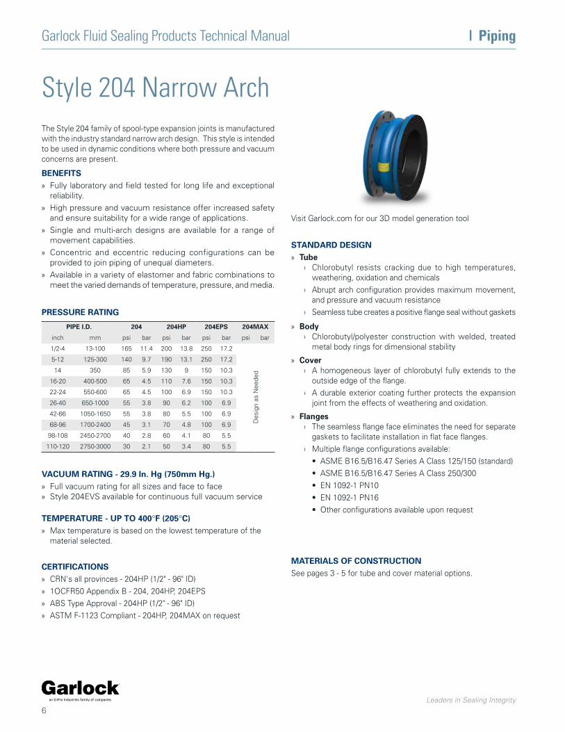
Style 204 Narrow ArchThe Style 204 family of spool-type expansion joints is manufactured with the industry standard narrow arch design. This style is intended to be used in dynamic conditions where both pressure and vacuum concerns are present.
BENEFITS » Fully laboratory and field tested for long life and exceptional
reliability.
» High pressure and vacuum resistance offer increased safety and ensure suitability for a wide range of applications.
» Single and multi-arch designs are available for a range of movement capabilities.
» Concentric and eccentric reducing configurations can be provided to join piping of unequal diameters.
» Available in a variety of elastomer and fabric combinations to meet the varied demands of temperature, pressure, and media.
TEMPERATURE - UP TO 400°F (205°C) » Max temperature is based on the lowest temperature of the
material selected.
VACUUM RATING - 29.9 In. Hg (750mm Hg.) » Full vacuum rating for all sizes and face to face » Style 204EVS available for continuous full vacuum service
PIPE I.D. 204 204HP 204EPS 204MAX
inch mm psi bar psi bar psi bar psi bar
1/2-4 13-100 165 11.4 200 13.8 250 17.2
Des
ign
as N
eede
d
5-12 125-300 140 9.7 190 13.1 250 17.2
14 350 85 5.9 130 9 150 10.3
16-20 400-500 65 4.5 110 7.6 150 10.3
22-24 550-600 65 4.5 100 6.9 150 10.3
26-40 650-1000 55 3.8 90 6.2 100 6.9
42-66 1050-1650 55 3.8 80 5.5 100 6.9
68-96 1700-2400 45 3.1 70 4.8 100 6.9
98-108 2450-2700 40 2.8 60 4.1 80 5.5
110-120 2750-3000 30 2.1 50 3.4 80 5.5
STANDARD DESIGN » Tube
› Chlorobutyl resists cracking due to high temperatures, weathering, oxidation and chemicals
› Abrupt arch configuration provides maximum movement, and pressure and vacuum resistance
› Seamless tube creates a positive flange seal without gaskets
» Body › Chlorobutyl/polyester construction with welded, treated
metal body rings for dimensional stability
» Cover › A homogeneous layer of chlorobutyl fully extends to the
outside edge of the flange.
› A durable exterior coating further protects the expansion joint from the effects of weathering and oxidation.
» Flanges › The seamless flange face eliminates the need for separate
gaskets to facilitate installation in flat face flanges.
› Multiple flange configurations available:
• ASME B16.5/B16.47 Series A Class 125/150 (standard)
• ASME B16.5/B16.47 Series A Class 250/300
• EN 1092-1 PN10
• EN 1092-1 PN16
• Other configurations available upon request
CERTIFICATIONS » CRN's all provinces - 204HP (1/2" - 96" ID)
» 1OCFR50 Appendix B - 204, 204HP, 204EPS
» ABS Type Approval - 204HP (1/2" - 96" ID)
» ASTM F-1123 Compliant - 204HP, 204MAX on request
Visit Garlock.com for our 3D model generation tool
PRESSURE RATING
MATERIALS OF CONSTRUCTIONSee pages 3 - 5 for tube and cover material options.

Leaders in Sealing Integrity
7
Piping | Garlock Fluid Sealing Products Technical Manual
OPTIONAL CONFIGURATIONS
Concentric Reducing Eccentric Reducing Unique Drill Patterns per flange
Angular Offset Lateral Offset Filled Arches Multiple Arches
MOVEMENT CAPABILITIES
STANDARD FACE TO FACE
NOMINAL ID
COMPRESSION ELONGATION LATERAL
inch mm inch mm inch mm inch mm
1/2-1-1/2 13-40 0.25 6 0.125 3 0.25 6
2-6 50-150 0.5 13 0.25 6 0.5 13
8-18 200-450 0.75 19 0.375 10 0.5 13
20-24 500-600 0.875 22 0.4375 11 0.5 13
26-40 650-1000 1 25 0.5 13 0.5 13
42-120 1050-3000 1.125 29 0.5 13 0.5 13
NOMINAL ID 1 ARCH 2 ARCH 3 ARCH 4 ARCH
inch mm inch mm inch mm inch mm inch mm
1/2-8 13-200 6 150 10 250 14 350 18 450
10-20 250-500 8 200 12 300 16 400 20 500
22-40 550-1000 10 250 14 350 18 450 22 550
42-120 1050-3000 12 300 16 400 20 500 24 600
NOTES: 1. Movements listed are per arch. Movements are reduced by half for filled arches. Movements listed are non concurrent. For concurrent movements,
contact Garlock.2. Pipe sizes through 1½" are supplied with a filled arch, and movements have been reduced accordingly.
NOTES: 1. Multiple arches not available with GUARDIAN® FEP Liners, or Reducing Expansion Joints2. For shorter "FF" dimensions, consult Garlock
NOTES: 1. GUARDIAN® FEP Liners not available with all options. For specific inquires contact Garlock.

Garlock Fluid Sealing Products Technical Manual | Piping
Leaders in Sealing Integrity
8
Style 206 EZ-FLO®
The Style 206 EZ-FLO family of expansion joints is constructed with a single, wide, flowing arch. It is intended for use in dynamic, high-pressure applications where low spring rates and a self-flushing arch are required.
BENEFITS
» Self-flushing design eliminates media buildup and reduces fluid turbulence
» High pressure ensures longer life and reduces inventory requirements
» Lightweight design installs easily
STANDARD DESIGN
» Tube › Chlorobutyl resists cracking due to high temperatures,
weathering, oxidation and chemicals
› Flowing arch design adds pressure resistance and reduces product buildup
» Body › The rubber reinforced nylon tire cord and polyester
construction provide flexibility as well as durability.
» Cover › A homogeneous layer of chlorobutyl fully extends to the
outside edge of the flange.
› A durable exterior coating further protects the expansion joint from the effects of weathering and oxidation.
» Flanges › The seamless flange face eliminates the need for separate
gaskets to facilitate installation in flat face flanges.
› Multiple flange configurations available:
• ASME B16.5/B16.47 Series A Class 125/150 (standard)
• ASME B16.5/B16.47 Series A Class 250/300
• EN 1092-1 PN10
• EN 1092-1 PN16
• Other configurations available upon request
TEMPERATURE - UP TO 300°F (150°C)
» Max temperature is based on the lowest temperature of the material selected.
PRESSURE & VACUUM RATING
PIPE I.D. STANDARDFACE TO FACE PRESSURE VACUUM
Inch mm Inch mm psi bar in. Hg mm Hg
1-8 25-200 6 150 250 17.2 26 650
10 250 8 200 250 17.2 26 650
12 300 8 200 250 17.2 12 300
14 350 8 200 130 9 12 300
16-20 400-500 8 200 110 7.6 12 300
22-24 550-600 10 250 100 6.9 12 300
26-40 650-1000 10 250 90 6.2 12 300
42-66 1050-1650 12 300 80 5.5 12 300
68-96 1700-2400 12 300 70 4.8 12 300
98-108 2450-2700 12 300 60 4.1 12 300
110-120 2750-3000 12 300 50 3.4 12 300
* Pressure and vacuum ratings at neutral FF dimension. Extended face to face dimensions result in reduced pressure and vacuum ratings for Style 206 EZ-FLO® expansion joints.
CERTIFICATIONS AND COMPLIANCE » ABS Type Approved (2" - 48" ID)
» ISO 15540 Fire Safe***
» 1OCFR50 Appendix B
» ASTM F1123 compliant
» 46CFR56 (USCG)
» CRN - All provinces (2" - 48" ID)
*** Requires use of fire safe cover
Visit Garlock.com for our 3D model generation tool
MATERIALS OF CONSTRUCTIONSee pages 3 - 5 for tube and cover material options.

Leaders in Sealing Integrity
9
Piping | Garlock Fluid Sealing Products Technical Manual
MOVEMENT CAPABILITIES
NOTES: Movements are reduced by half with GUARDIAN® FEP liners. Movements listed are non-concurrent. For concurrent movements, contact Garlock.
OPTIONAL CONFIGURATIONS
NOMINAL ID
COMPRESSION ELONGATION LATERAL
inch mm inch mm inch mm inch mm
1-5 25-125 0.75 19 0.375 10 0.5 13
6-18 150-450 1 25 0.5 13 0.5 13
20-24 500-600 1.125 29 0.5 13 0.5 13
26-40 650-1000 1.25 32 0.5 13 0.5 13
42-120 1050-3000 1.375 35 0.5 13 0.5 13
Angular Offset Unique Drill Patterns per flange Lateral Offset

Garlock Fluid Sealing Products Technical Manual | Piping
Leaders in Sealing Integrity
10
Styles 214, 215These PTFE concentric spool-type flexible couplings are designed to reduce noise and compensate for expansion, contraction and minor piping misalignment in chemical processing, air conditioning and heating systems.
STYLE 214
» Two convolutions » Temperature: -100°F (-70°C) to +450°F (+230°C)
Pressure: To 178 psig (12 bar), Full vacuum to +350°F (+180°C)
STYLE 215
» Three convolutions » Temperature: -100°F (-70°C) to +450°F (+230°C)
Pressure: To 132 psig (9 bar), Full vacuum to +180°F (+80°C)
STYLE 216
» Custom Option / Engineered Solution for up to 24 inch inner diameter and multiple convolutions
BENEFITS
» The convolution shape provides extra-long flex life at high temperatures
» The proprietary contour molding process ensures consistent wall thickness for improved blowout resistance
» PTFE body withstands corrosion, water, steam, and most chemicals and gases
» Preset tie rods prevent over-extension
» Available silicone-free upon request
PRESSURE RATING
Garlock PTFE expansion joints and couplings have pressure ratings high enough to handle most applications. As the pipe size gets larger, Garlock increases the bellows thickness and the strength of the reinforcing rings to compensate for the change in internal forces. This permits the same high pressure rating for all sizes.
TEMPERATURE 214 PRESSURE 215 PRESSURE
psi bar psi bar
50˚F 10˚C 178 12 132 9
100˚F 50˚C 165 11 120 8
150˚F 65˚C 150 10 103 7
200˚F 90˚C 130 9 90 6
250˚F 120˚C 110 8 75 5
300˚F 150˚C 92 6 60 4
350˚F 180˚C 78 5 50 3.5
400˚F 205˚C 65 4.5 42 3
450˚F 230˚C 60 4 35 2
STANDARD DESIGN
» Complete assembly includes
› Fluorocarbon resin PTFE body
› Electroless nickle-plated ductile iron flanges
› Polyethylene-covered restriction zinc plated bolts
› Stainless steel corrosion-resistant reinforcing rings
» Standard sizes from 1” (25mm) through 24” (800mm) pipe I.D.
» Available with 304 or 316 stainless steel flanges and tie rods upon request

Leaders in Sealing Integrity
11
Piping | Garlock Fluid Sealing Products Technical Manual
MOVEMENT CAPABILITIES
Pipe Size (Inches) 1 1-1/2 2 2-1/2 3 4 5 6 8 10 12 14 16 18 20 24
Nominal Installed Face to-Face
1-3/8 1-3/8 1-9/16 2-1/4 2-1/4 2-5/8 3-1/4 2-3/4 4 3-1/16 3-1/4 3-9/16 3-11/16 4-1/8 4-3/16 4-1/8
Max. Axial Movement, + or -
1/4 1/4 1/4 5/16 3/8 1/2 1/2 1/2 1/2 5/8 5/8 21/32 21/32 21/32 11/16 11/16
Max. Transverse Deflection, + or -
1/8 1/8 1/8 1/8 3/16 1/4 1/4 1/4 1/4 3/8 3/8 3/8 3/8 3/8 13/32 13/32
Maximum angular movement approximately 7˚.* Based on unit being in normal installed position with no axial movement or angular deflection.
Tie
Rod
Set
ting
Max
.
Face
-to-
Face
Dim
ensi
on
Style 214 PTFE Flexible Coupling
Pipe Size (Inches) 1 1-1/2 2 2-1/2 3 4 5 6 8 10 12 14 16 18 20 24
Nominal Installed Face to-Face
1-3/4 2 2-3/4 3-3/16 3-5/8 3-5/8 4 4 6 4-1/4 4-7/16 4-13/16 4-15/16 5-7/16 5-1/2 5-1/2
Max. Axial Movement, + or -
1/2 1/2 3/4 3/4 1 1 1 1-1/8 1-1/8 15/16 15/16 1 1 1 1-1/16 1-1/16
Max. Transverse Deflection, + or -
1/4 1/4 3/8 3/8 1/2 1/2 1/2 9/16 9/16 9/16 9/16 9/16 9/16 9/16 5/8 5/8
Maximum angular movement approximately 14˚.* Based on unit being in normal installed position with no axial movement or angular deflection.
Style 215 PTFE Flexible Coupling
PTFE CONTROL UNITS AND FLANGES
All PTFE joints and couplings are furnished with ductile iron flanges and control units ready for immediate installation on the job site. Flanges in other alloys are available by special order.
Flanges are protected to resist atmosphere corrosion and are tapped to ASME B16.5/B16.47 Series A Class 125/150 (standard).
Control units are assembled with flanges to prevent joints from excessive axial elongation. They are designed to accept the static pressure thrust in the piping system.
Tie rods are factory set to maximum face-to-face working limits, with lock nuts as insurance against over-extension of the expansion joint.The polyethylene covered tie rods eliminate metal to metal contact between the rods and the flanges; the most frequent cause of noise transmission and electrolysis.
Pipe Size (Inches) 1 1-1/2 2 2-1/2 3 4 5 6 8 10 12 14 16 18 20 24
Flange Dimensions
Outside Diameter 5-13/16 6-11/16 7-7/16 8-7/16 9-3/16 10-11/16 11-11/16 13-1/4 15-3/4 18-1/8 20-1/2 23-1/16 25-1/16 27-9/16 30-7/8 35-7/16
Thickness 3/8 3/8 1/2 5/6 5/8 11/16 11/16 11/16 11/16 13/16 13/16 13/16 15/16 1-1/16 1-1/16 1-1/8
FLANGE DIMENSIONS AND DRILLING
Tie
Rod
Set
ting
Max
.
Face
-to-
Face
Dim
ensi
on

Garlock Fluid Sealing Products Technical Manual | Piping
Leaders in Sealing Integrity
12
GARFLEX® 8100GARFLEX® expansion joints feature rugged yet flexible nylon tire cord reinforcement in a molded, spherical bellows design that ensures exceptional burst pressure ratings. The streamlined flowing arch design reduces turbulence and allows smooth, quiet flow without the restricted movement you'll find with a filled arch design.
BENEFITS » Flowing arch design prevents sediment buildup and reduces
turbulence
» Floating flanges can be rotated to accommodate torsional misalignment
» Can be installed against flat or raised face pipe flanges without the need for gaskets or spacers
» Molded spherical bellows accommodate up to one inch of axial movement and transverse deflection
» The nylon-reinforced nitrile provides the support needed for higher pressure applications without sacrificing flexibility while also providing resistance to most hydrocarbons, oils, and gasoline.
STANDARD DESIGN » Tube
› Nitrile bellows with rugged nylon tire cord reinforcement ensure strength without sacrificing flexibility
› Incorporates a flowing arch design to eliminate product buildup
» Cover › The homogeneous layer of neoprene rubber can withstand
the rigors of weathering and ozone.
» Flanges › Ductile iron flanges with a rust-resistant coating
Note: Style 8100 expansion joints are supplied with rotating flanges drilled to ASME B16.5/B16.47 Series A Class 125/150 (standard).* Retaining Rings for 10"/12" ID joints have control units built in.
OPERATING TEMPERATURE PRESSURE
˚F ˚C psi bar
up to 122˚ up to 50˚ 232 16
123˚ - 158˚ 50˚ - 70˚ 174 12
159˚ - 194˚ 70˚ - 90˚ 139 9.5
195˚ - 210˚ 90˚ - 100˚ 70 5
211˚ - 230˚ 100˚ - 110˚ 25 1.7
TEMPERATURE / PRESSURE RATINGNylon-Reinforced Nitrile
PIPE I.D. VACUUM
Inch mm in. Hg mm Hg
2 - 2-1/2 50 - 63 23 575
3 75 20 500
4 100 17 425
5 - 6 125 - 150 11 275
8 200 8 200
10 - 12 250 - 300 5 125
VACUUM RATING*
MOVEMENT
Type Movement Inch mm
Compression 1 25
Elongation 1 25
Transverse Deflection (at recommended installed position)
±1 ±25
MOVEMENT CAPABILITIES
Movements are non-concurrent.
* At nominal FF dimensions only.
Type Movement
PIPE I.D.Max.
AllowedInch mm
Angular Deflection (at recommended installed position)
2 50 35˚
2-1/2 - 3 63 - 75 30˚
4 100 25˚
5 - 6 125 - 150 20˚
8 200 15˚
10 - 12 250 - 300 10˚
Nominal F-F (in.)
Nominal Bellow I.D. (inch)
2 2.5 3 4 5 6 8 10 12
5 • • • • • • • • •
6 • • • • • • • NA NA
8 NA NA NA NA NA NA NA • •
BELLOW SIZES
CERTIFICATIONS AND COMPLIANCE » ABS Type Approved (2" - 12" ID)
» ISO 15540 Fire Safe***
» ASTM F1123 Compliant
» 46CFR56 (USCG)
*** Requires use of fire safe cover

Leaders in Sealing Integrity
13
Piping | Garlock Fluid Sealing Products Technical Manual
Style 7250 FLEXO-MATIC™
The 7250 FLEXO-MATIC™ is designed to absorb noise and vibration in air-conditioning, heating, and industrial piping systems.
BENEFITS » Eliminating noise at its source, Garlock FLEXO-MATIC™ rubber
connectors are designed to absorb equipment noise before it is transmitted through piping systems.
» Because high-frequency vibrations are virtually eliminated, the FLEXO-MATIC™ helps extend equipment life.
» Expansion, contraction, and misalignment are all compensated for with FLEXO-MATIC™ connectors.
» The FLEXO-MATIC™ absorbs water hammer (vibration of the fluid media itself) as well as compensates for expansion, contraction, and misalignment.
» No risk of electrolytic corrosion since there is no metal-to-metal contact between the connectors and metal piping.
PRESSURE & VACUUM RATING
PIPE I.D. PRESSURE VACUUM
inch mm psi bar in. Hg mm Hg
2 - 16 50 - 400 150 10.3 29.9 750
18 - 24 450 - 600 100 6.9 29.9 750
TEMPERATURE - UP TO 400°F (205°C) » Max temperature is based on the lowest temperature of the
material selected.
STANDARD SIZES
PIPE I.D. RECOMMENDED LENGTH
inch mm inch mm
0 - 2.5 0 - 65 12 305
3 - 4 75 - 100 18 457
5 - 24 125 - 600 24 610STANDARD DESIGN » Tube
› A protective, leakproof lining made of a synthetic rubber which may vary depending on the service.
» Body › Fabric Reinforcement–Polyester, or other suitable fabrics
impregnated with an elastomer are wrapped and plied to provide the flexibility and support required between the tube and cover.
› Metal Reinforcement–Helical-wound steel reinforcement wire is firmly embedded in the body to provide resistance to both vacuum and pressure.
» Cover › A homogeneous layer of synthetic rubber to protect the
body from corrosive attack or mechanical damage, the rugged cover withstands aging and weathering for a long, trouble-free life.
» Flanges › Seamless flange face eliminates need for gaskets
› Standard flange (ASME B16.5/B16.47 Class 125/150 Series A)
› Also available in;
• ASME B16.5/B16.47 Class 250/300 Series A
• EN 1092-1 PN10
• EN 1092-1 PN16
› Contact Garlock for all others
OPTIONAL CONFIGURATIONS
Angular Offset Lateral Offset
Unique Drill Patterns per flange
MATERIALS OF CONSTRUCTIONSee pages 3 - 5 for tube and cover material options.

Leaders in Sealing Integrity
14
Garlock Fluid Sealing Products Technical Manual | Low Pressure/Ducting
Style 9394This multi-convolute, lightweight expansion joint is designed for lower pressure applications that require significant amounts of movement, axially and/or laterally. With low spring rates, it is ideal for load cell applications as well.
BENEFITS » The lightweight design installs easily and carries the added
bonus of reduced shipping costs when compared to higher pressure designs.
» Custom designs available for applications requiring greater than published movement ratings.
» A variety of construction materials are available for a wide range of temperature needs.
» Available in flanged or sleeve type design, up to 48" max. (1,219 mm) I.D. *Contact Garlock for larger ID sizes
» Flanges › The seamless flange face eliminates the need for separate
gaskets to facilitate installation in flat face flanges
› Multiple flange configurations available:
• ASME B16.5/B16.47 Series A Class 125/150 (standard)
• ASME B16.5/B16.47 Series A Class 250/300
• EN 1092-1 PN10
• EN 1092-1 PN16
• Other configurations available upon requestNOTE: To achieve an effective seal, flanged designs must be installed with retaining rings, sleeve designs installed with clamping rings. The overall length of the sleeve should include an additional 4 inches (101.6mm) for clamping space.
PRESSURE RATING » Without external reinforcing rings: up to 3 psi (0.2 bar)
» With external reinforcing rings: up to 15 psi (1.0 bar)
VACUUM RATING » Without internal reinforcing rings: up to 3 inches
(75 mm) Hg
» With internal reinforcing rings: up to 15 inches (381 mm) Hg
Contact Garlock if higher vacuum or pressure ratings are required.
F-F
Optional Reinforcing Rings
Cross Section of Style 9394 w/ optional Reinforcing Rings
OPTIONAL CONFIGURATIONS
STANDARD FACE TO FACE
NUMBER OF CONVOLUTIONS
MIN. F - F
inch mm
1 4.5 114
2 6 152
3 7.5 191
4 9 229
Angular Offset Lateral OffsetSleeve Connection
Unique Drill Patterns per flange
MOVEMENT CAPABILITIES PER CONVOLUTION
NOMINAL ID
COMPRESSION ELONGATION LATERAL
inch mm inch mm inch mm inch mm
2 - 6 50 - 150 3/4 19 5/8 16 5/8 16
8 - 10 200 - 250 7/8 22 3/4 19 3/4 19
12 - 18 300 - 450 1-1/8 28 1 25 1 25
20 - 48 500 - 1200 1-5/8 41 1-1/4 31 1-1/4 31
MATERIALS OF CONSTRUCTIONSee pages 3 - 5 for tube and cover material options.
TEMPERATURE - UP TO 400°F (205°C) » Max temperature is based on the lowest temperature of the
material selected.

Leaders in Sealing Integrity
15
Low Pressure/Ducting | Garlock Fluid Sealing Products Technical Manual
Style 8400Garlock offers a wide range of duct type expansion joints for lightweight applications, especially for scrubbers, precipitators, bag houses, and fans in air handling systems. Style 8400 expansion joints are available in round, rectangular or square configurations, as belt type (without flanges) or U-type (flanged), with virtually no size restrictions.
RECTANGULAR / SQUARE » Face-to-face dimensions: typically 6" (152 mm), 9" (229 mm)
or 12" (305 mm)
» If any side is smaller than 24" (600 mm), joint will be built on a metal form with column corners
NOTE: Other sizes also available. If more movement is required, please contact Garlock.
ROUND » Supplied in any size, with or without flanges or arch
» Movement capabilities depend on expansion joint size and arch configuration
BELT TYPE
» Supplied in any size, without flanges, with or without an arch
» Available in the same materials as Style 8400 round expansion joints
» Movement capabilities depend on installation width and arch configuration
» Supplied open-ended (wraparound), or continuous to fit over ducting
TEMPERATURE - UP TO 400°F (205°C)
Max temperature is based on the lowest temperature of the material selected.
PRESSURE RATING - 3psi (.2 bar)
VACUUM RATING - 6 In. Hg. (152 mm Hg.)
MOVEMENT CHART - FLOWING ARCH
MOVEMENT CHART - EZ-FLO™ ARCH
MOVEMENT CHART - NO ARCH
F - F Max. Compression Max. Elongation Max. Lateral
inch mm inch mm inch mm inch mm
6 150 1½ 38 ½ 13 ±1 25
9 225 3 76 1 25 ±2 50
12 300 4 100 1 25 ±2½ 63
16 400 6 150 1 25 ±3½ 89
ID Max. Compression
Max. Elongation Max. Lateral
inch mm inch mm inch mm inch mm
1"-5" 25-125 0.75 19 0.375 10 0.5 13
6"-18" 150-450 1 25 0.5 13 0.5 13
20"-24" 500-600 1.125 29 0.5 13 0.5 13
26"-40" 650-1000 1.25 32 0.5 13 0.5 13
42"-120" 1050-3000 1.375 35 0.5 13 0.5 13
ID/Face to Face
Max. Compression Max. Elongation Max. Lateral
inch mm inch mm inch mm
All sizes 1/4 6 1/4 6 1/4 6
MATERIALS OF CONSTRUCTIONSee pages 3 - 5 for tube and cover material options.
NOTE: Available with 3" wide flanges only and 24" minimum ID

Leaders in Sealing Integrity
16
Garlock Fluid Sealing Products Technical Manual | Low Pressure/Ducting
Style 8420 SplitEasy installation and removal
» Split design eliminates equipment disassembly, reducing costly downtime.
» Available in EPDM, Nitrile* and Fluoroelastomer in sizes from 2" to 24" standard. Contact Garlock for larger sizes.
» Can be customized for your application; contact Garlock with your specifications.
* EPDM and nitrile are standard - other elastomers available on request.
Unassembled view
SPECIFICATIONS
2" Max. Pipe Gap Opening
4" Max. Pipe Gap Opening
6" Max. Pipe Gap Opening
Clamps Required: 4 4 4
Thickness:2"-12" Size(50.8mm-304.8mm)
1/4"(6.4mm)
1/4"(6.4mm)
1/4"(6.4mm)
14"-24" Size(355.6mm-609.6mm)
3/8"(9.5mm)
3/8"(9.5mm)
3/8"(9.5mm)
Pressure, Max: 15psi(1.043 bar)
5psi(0.345 bar)
5psi((0.345 bar)
Vacuum: 14" Hg(356mm Hg)
5" Hg(127mm Hg)
5" Hg(127mm Hg)
Temperature, Max.with standard adhesive kit
165˚F(74˚C)
165˚F(74˚C)
165˚F(74˚C)
with Viton* adhesive400˚F
(204˚C)400˚F
(204˚C)400˚F
(204˚C)
Movement: Vibration Only Vibration Only Vibration Only
Lateral Misalignment, Max.:
1/2"(12.7mm)
1/2"(12.7mm)
1/2"(12.7mm)
Width of Joint:(203.2mm)
8"(203.2mm)
10"(254mm)
12"(304.8mm)
NOTES:1. All applications above 165˚F (74˚C) require Viton* adhesive kits2. T-bolt clamps recommended on all applications. Garlock does not supply
clamping hardware
3. Adhesive kits are sold separately
* Viton is a registered trademark of DuPont Dow Elastomers

Leaders in Sealing Integrity
17
Low Pressure/Ducting | Garlock Fluid Sealing Products Technical Manual
Customization CapabilitiesGarlock Expansion Joints are engineered, designed and manufactured in Palmyra, NY. Our team is available to help solve your unique problems. Garlock specializes in designing and manufacturing expansion joints customized to the application while providing the customer with a seamless installation.
EXPANSION JOINT DESIGN
Despite the best efforts, real world piping is never as perfect as designed on paper. Foundations settle, pumps are not installed in the exact location designed, and space is limited. Standard expansion joints are not always ideal and customized joints are the solution to real world problems. From non-standard sizes to unique flange connections, Garlock has the experience and expertise to design an expansion joint to meet your system demands.
ACCESSORIES DESIGN
With custom expansion joints provided by Garlock, accessories for these special products are available to ensure the full spectrum of the application needs are fulfilled. Technical experts at Garlock specialize in tailoring the following accessories:
TESTING/CERTIFICATION
Garlock maintains material traceability on all materials in stock so there is not an extended wait when traceability or raw material test reports are required. 24 hour access is available for any required customer witness points and inspections at any point of the manufacturing process.
MATERIALS
Garlock can provide the optimum materials for the specific application and is not limited to the industry standard tube and cover combinations that most manufacturers carry. Garlock Material Engineers can formulate compounds in house to meet the specific elastomer specifications required. With small batch sizes available, large lot sizes are not required.
OTHER CUSTOMIZATION
Contact Garlock for any specific request and our team will work to accommodate.
» Non standard ID » Oversized arches » Multiple arches » Vacuum support rings » Factory splicing
» Oversized bolt holes » Non standard flanges » Lightweight designs » Non-standard shapes » Sealed/Painted bolt holes
» Threaded bolt holes on retaining rings » Custom control units to accommodate offset » Integrating control units with retaining rings » Stainless steel, galvanized and uncoated material options » Speciality metal Flow Liners
» Material combinations » Specific elastomer specifications » Small batch sizes
» Labeling » Imbedded, metal, paper, and weather proof tagging » Packaging » CAD drawings » 3D Models
» Materials traceability » Raw material test reports » Witness points » Outside inspectors
» Accelerated life test » Welding certifications/testing » Hydrostatic/air pressure
testing

Garlock Fluid Sealing Products Technical Manual
Leaders in Sealing Integrity
18
Expansion Joint AccessoriesMETAL FLOW LINERS » A metallic flow liner can extend service life by protecting the
expansion joint from abrasive materials or solids, particularly in high-velocity applications.
» Flanged at one end, flow liners are installed with the flange at the head of the media flow. They are designed with a 5 degree taper to allow for lateral movement.
» Liner flange thickness:10 gauge Liner body thickness: 12 gauge
» Recommended for Flow Rates: 8 fps
» Available in 304/316 stainless steel; also, titanium, Hastelloy C, and other materials upon request
» Special configurations available for reducing and multi-arch designs. Please contact Garlock for additional information.
Retaining Ring Expansion Joint
Gasket Flow Liner
METAL FLOW LINER INSTALLATION
CONTROL UNITS » Control units are recommended for most applications to prevent
damage to the expansion joint from excessive pipe movement.
» A control unit assembly consists of two or more tie rods connected between pipe flanges.
» Triangular end plates (gussets) come complete with two holes for secure bolting to the flange and one hole to accommodate the connecting tie rod.
» Spherical washers are incorporated to accommodate moderate piping misalignment and to assist with angular, torsional, and lateral movements.
» Each rod incorporates double nuts on each end to prevent over-elongation of the expansion joint.
» When excessive axial compression is a concern, compression nuts can be incorporated to prevent damage as a result of over-compression.
» Please note, control units are NOT intended as a replacement for adequate pipeline anchoring.
TYPICAL CONTROL UNIT FOR RUBBER EXPANSION JOINT
FIRE RESISTANT COVERS
Recommended on applications where flammable liquids are being used or in fire water systems.
» Constructed from several layers of fiberglass fabric with a surface layer of silver-covered, high-temperature resistant silicone aluminum-glass fabric.
» Tested to ISO 15540 at 1472°F (800˚C) for 30 minutes for fire resistance
» Provided as a split design to allow for easy installation and inspection.
» The cover is oil-resistant, providing added protection against weather and aging of the expansion joint.
METAL RETAINING RINGS » Retaining rings are required for all expansion joint installations.
The metal surface of the ring equally distributes the bolting pressure, preventing flange damage during bolt tightening.
» Rings should be installed against the expansion joint's external flange.
» Standard material of construction is mild steel with a corrosion-resistance coating; galvanized and stainless steel options available upon request.

Garlock Fluid Sealing Products Technical Manual
Leaders in Sealing Integrity
19
Industry SpecificsNUCLEARGarlock is the only manufacturer of nuclear safety-related elastomeric expansion joints in the United States. Garlock maintains an active nuclear quality program in accordance with 10CFR50 Appendix B and 10CFR21 for select product offerings as detailed in our Quality Manual. We have been an ISO 9001 registered company since 1994 and are regularly audited by NUPIC (Nuclear Procurement Issues Committee) audit teams. Here are a couple of our key products for the nuclear industry:
» Style 204/204HP
» Style 206
U.S. NAVYGarlock manufactures numerous expansion joints in accordance with U.S. Navy specifications. U.S. Navy specification MIL-E-15330D was superseded by ASTM F1123. Contact the product line for information relating to other military specifications.
» Style 206
» Style 204 HP
U.S. COAST GUARDGarlock manufactures to applicable Code of Federal Regulations and ASTM standards. 46CFR56 series » Style 206
» Style 204HP
» Style 8100
INTERNATIONALGarlock has undergone design review and received provincial Canadian Registration Number (CRN) - (all provinces) » Style 204HP
» Style 206
Canadian Registration Number (CRN) - Alberta » Style 404HP
» Style 406
ABS TYPE APPROVAL » Style 206
» Style 8100
» Style 204HP
FIRE RESISTANCE ISO 15540* » Style 206
» Style 8100* with use of fire safe cover
FDA - COMPLIANT TO 21CFR 177.2600 » Style 206
» Style 204
» Style 7250
» Style 8420 (204EPS)
» Style 204EVS
» Style 7706-S Type
» Style 8100
Style 204HP
Style 7706
Style 8100
Style 204
» Style 9394
» Style 8400

Garlock Fluid Sealing Products Technical Manual
Leaders in Sealing Integrity
20
Types of Expansion JointsSINGLE ARCH » Fabric and rubber construction
» Reinforced with metal/wire rings
» Full-face flanges integral with joint body
MULTIPLE ARCH » Accommodates greater movement than single arch
» Minimum joint length depends on number of arches
» Maximum of four arches recommended to maintain lateral stability
SLEEVE » Same as single arch type, except sleeve end I.D. equals pipe O.D.
» Slips over straight ends of open pipe
» Ends secured by suitable clamps
» Recommended for low pressure service only
TAPER OR REDUCER » Connects piping of different diameters
» Concentric tapered joints: same axis for both ends
» Eccentric: axis of one end offset from other end
» Tapers in excess of 25˚ are not recommended
» Pressure ratings are based on larger I.D.
» Available with or without arches
» Flanges drilled to companion bolt pattern
» Gaskets not required
» Offset
Garlock Fluid Sealing Products Technical Manual
Leaders in Sealing Integrity
21
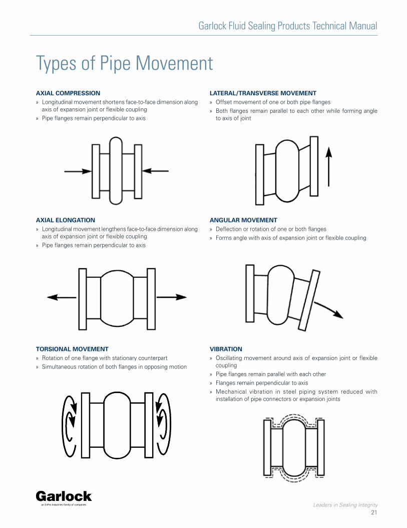
Types of Pipe MovementAXIAL COMPRESSION » Longitudinal movement shortens face-to-face dimension along
axis of expansion joint or flexible coupling
» Pipe flanges remain perpendicular to axis
AXIAL ELONGATION » Longitudinal movement lengthens face-to-face dimension along
axis of expansion joint or flexible coupling
» Pipe flanges remain perpendicular to axis
TORSIONAL MOVEMENT » Rotation of one flange with stationary counterpart
» Simultaneous rotation of both flanges in opposing motion
LATERAL/TRANSVERSE MOVEMENT » Offset movement of one or both pipe flanges
» Both flanges remain parallel to each other while forming angle to axis of joint
ANGULAR MOVEMENT » Deflection or rotation of one or both flanges
» Forms angle with axis of expansion joint or flexible coupling
VIBRATION » Oscillating movement around axis of expansion joint or flexible
coupling
» Pipe flanges remain parallel with each other
» Flanges remain perpendicular to axis
» Mechanical vibration in steel piping system reduced with installation of pipe connectors or expansion joints

Garlock Fluid Sealing Products Technical Manual
Leaders in Sealing Integrity
22
Typical Properties of ElastomersMaterial
Designation Rating Scale Code Elastomer Physical and Chemical Properties Comparison
AN
SI /
AS
TMD
1418
-77
AS
TM D
-200
0D
1418
-77
7 - Outstanding 3 - Fair to Good
Wat
er
Che
mic
al
Ani
mal
& V
eget
able
Oil
Alk
ali,
Con
dens
ed
Alk
ali,
Dilu
te
Oil
& G
asol
ine
Lacq
uers
Oxy
gena
ted
Hyd
roca
rbon
s
Aro
mat
ic H
ydro
carb
ons
Alip
hatic
Hyd
roca
rbon
s
Aci
d, C
once
ntra
ted
Aci
d, D
ilute
Sw
ellin
g in
Oil
Rad
iatio
n
Wat
er A
bsor
ptio
n
Ele
ctric
Insu
latio
n
Die
lect
ric S
tren
gth
Tens
ile S
tren
gth
Com
pres
sion
Set
Reb
ound
, Col
d
Reb
ound
, Hot
Dyn
amic
Impe
rmea
bilit
y
Abr
asio
n
Tear
Flam
e
Col
d
Hea
t
Oxi
datio
n
Sun
light
Wea
ther
Ozo
ne
6 - Excellent 2 - Fair
5 - Very Good 1 - Poor to Fair
4 - Good 0 - Poor
4* - good @ room temp, poor above 180˚F (80˚C)
X - Contact manufacturer
COMMON NAMEChemical Group Name
CR BCBE
NEOPRENEchloroprene 4 3 4 0 4 4 0 1 2 3 4 6 4 5 4 3 5 4 2 4 5 2 4 5 4 4 4 4 5 5 6 5
NR AA NATURAL RUBBERpolyisoprene, synthetic 5 3 X X X 0 0 4 0 0 3 3 0 6 5 5 6 6 4 6 6 6 2 7 5 0 5 2 4 0 2 0
CIIR AABA
CHLOROBUTYLchloro-isobutene-isoprene 5 6 5 4 4 0 3 4 0 0 4 6 0 4 5 5 5 4 3 0 5 2 6 4 4 0 4 5 6 5 5 6
NBRBEBKCH
BUNA-N / NITRILEnitrile-butadiene 4 3 5 0 4 5 2 0 4 6 4 4 5 5 4 1 0 5 5 4 4 5 4 4 3 0 3 4 4 0 2 2
HNBR DH HNBRhydrogenated-nitrile-butadiene 4 3 5 0 4 6 2 0 4 6 4 4 6 5 4 1 0 5 6 4 4 5 4 7 6 0 3 6 4 0 2 2
CSM CE HYPALONchloro-sulfonyl-polyethylene 5 6 4 4 4 4 3 1 2 3 4 6 4 5 4 3 5 2 2 2 4 2 4 4 3 4 4 4 6 7 6 7
FKM HK VITON* / FLUOREL**fluorocarbon elastomer 5 6 6 0 4 6 1 0 6 6 6 5 6 5 5 3 5 5 6 2 4 5 5 5 2 6 2 7 7 7 7 7
EPDMBACADA
EPDMethylene-propylene-diene-
terpolymer5 6 5 6 6 0 3 6 0 0 4 6 0 7 6 6 7 5 4 6 6 5 4 5 4 0 5 6 6 7 6 7
AFMU TEFLON* / TFE / FEPfluoro-ethylene-polymers 7 7 7 7 7 7 7 7 7 7 7 7 7 3 7 X X X X X X X X 4 X X X 7 7 7 7 7
AU AABA POLYURETHANE 4* 3 5 0 1 5 1 2 3 6 0 1 6 6 4* 3 5 7 3 3 4 6 4 7 6 2 6 4 5 4 6 6
* Viton and Teflon are registered trademarks of The Chemours Co.** Fluorel is a registered trademark of 3M Companies.Kevlar is a registered trademarks of E.I. DuPont de Nemours & Co.
TEMPERATURE RATINGS
NOTE: All layers are rated for maximum temperature
Liner and/or Cover Material Min. Temp. Max. Temp.
Natural Rubber -77°F (-61°C) 180°F (80°C)
ABRA-LINE® -94°F (-70°C) 180°F (80°C)
Neoprene -25°F (-32°C) 250°F (120°C)
Hypalon (CSM) -30°F (-34°C) 250°F (120°C)
Nitrile -30°F (-34°C) 250°F (120°C)
Chlorobutyl -40°F (-40°C) 250°F (120°C)
EPDM -67°F (-55°C) 300°F (150°C)
ABRA-SHIELD™ -83°F (-64°C) 300°F (150°C)
HNBR -83°F (-64°C) 300°F (150°C)
Fluoroelastomer (FKM) -10°F (-23°C) 400°F (205°C)
GUARDIAN® FEP -100°F (-70°C) 400°F (205°C)
PTFE -100°F (-70°C) 450°F (230°C)
Body Material Max. Temp.
Polyester 250°F (120°C)
Nylon Tire Cord 250°F (120°C)
Kevlar® Tire Cord 300°F (150°C)
Fiberglass/Kevlar® 400°F (205°C)

Garlock Fluid Sealing Products Technical Manual
Leaders in Sealing Integrity
23
Expansion Joint Installation PREPARATION
Check service range » Double check performance limits against anticipated operating
conditions
» Check temperature, pressure, vacuum recommendations
» Check total joint deflection—alter as needed to reduce deflection to correct range
» Anchor lines
Check location » Proper location is usually close to main anchoring point
» Install pipe guide(s) for proper alignment
» Joint should absorb pipeline expansion / contraction between fixed anchor points
Check cover » Check outside joint cover for damage
» Cover will keep harmful materials from penetrating joint carcass
Check alignment » Alignment should be 0.125" (3.2 mm) or less
» If 0.125" (3.2mm) must be exceeded, use a special offset joint
Check support » Weight must not be carried by joint
» Support with hangers or anchors
Check flanges » Clean all mating flanges
» Do not gouge or mutilate surfaces during cleaning
» Carefully examine used parts for smoothness
INSTALLATION
Apply lubricant » On elastomeric joints only, not required with all PTFE- or FEP-
lined joints
» Coat rubber faces with graphite in water, or glycerine, to prevent joint adherence to pipe flanges
Insert bolts from arch side » On elastomeric joints only, not necessary with PTFE joints/
couplings with threaded holes
» Set bolt heads adjacent to arch
Tighten bolts » Elastomeric joints only, tighten gradually and equally, alternating
around flange
» Edges of joint must bulge slightly at flange O.D.
Check tightness » Within one week after application, then periodically
» In hot or cold water systems during cyclical changes
TYPICAL PIPING LAYOUT PROPER USE OF ANCHORS IN BRANCH CONNECTIONS
anchor anchor
expansion joints
elbow support (anchor to base)
solid foundation
pipe guides
anchor
solidfoundation
anchor
expansion joints

Garlock Fluid Sealing Products Technical Manual
Leaders in Sealing Integrity
24
Troubleshooting
General Precautions
FLANGE LEAKAGE » Check bolt tightness
» Check mating flange surface area for:
› Grooves
› Scratches
› Distorted areas
» Over-extension may indicate need for control units
LIQUID WEEPING FROM BOLT HOLES » Check tube portion of joint for leaks; replace if necessary
CRACKING AT BASE OF ARCH OR FLANGE » Check installed face-to-face dimensions for over-extension or
over-compression
» Check for proper pipe alignment: must not exceed 0.125" (3.2mm)
EXCESSIVE BALLOONING OF ARCH » Indicates distortion/deterioration of joint strengthening
members, or excessive system pressure
» Re-evaluate service conditions
» Install new joint
ELASTOMERIC JOINTS ONLY » Use proper care breaking seal
» Drive flanges apart gently with wooden wedges
» Bring insulation only to pipe flange—do not insulate over or around joint
› Covering joints may make leak detection difficult
› Insulation could restrict joint movement or cause overheating
» Store in cool, dry, dark area
» Do not rest on flange edges
» Carefully protect joints near welding operations
» Never install spool-type joints next to flangeless check valves or butterfly valves
» Install only against full-face metal flanges or damage/leakage could result; restrictions also apply to raised face or any non-full face flange
WARNING:Properties/applications shown throughout this brochure are typical. Your specific application should not be undertaken without independent study and evaluation for suitability. For specific application recommendations consult Garlock. Failure to select the proper sealing products could result in property damage and/or serious personal injury.
Performance data published in this brochure has been developed from field testing, customer field reports and/or in-house testing.
While the utmost care has been used in compiling this brochure, we assume no responsibility for errors. Specifications subject to change without notice. This edition cancels all previous issues. Subject to change without notice.
GARLOCK is a registered trademark for packings, seals, gaskets, and other products of Garlock.

Garlock Fluid Sealing Products Technical Manual
Leaders in Sealing Integrity
25
Expansion Joint Weights*
Joint Size(Inches)
Approx. lbs per Joint Approx. lbs / set
Face-to-Face Dimension Retaining Rings
Control Units6 inches 8 inches 10 inches 12 inches
2 3.5 4.0 - - 3.5 5.5
2½ 4.0 5.0 - - 5.0 6.5
3 4.5 5.5 - - 5.5 6.5
3½ 5.5 6.6 - - 6.5 6.5
4 6.5 7.8 - - 6.8 5.5
5 7.5 9.5 - - 7.5 10.5
6 8.8 11.5 13.8 15.5 8.8 10.5
8 12.5 15.0 20.0 22.0 12.5 10.5
10 16.0 23.5 25.0 28.0 15.8 22
12 - 28.8 35.0 41.5 23.5 22
14 - 38.0 45.0 53.0 25.5 29
16 - 48.0 52.0 60.0 31.0 29
18 - 50.0 55.0 68.0 29.5 29
20 - 55.0 67.0 78.0 36.0 26
24 - - 77.0 91.0 46.0 33
26 - - 92.0 110.0 50.0 52
28 - - 110.0 120.0 60.0 52
30 - - 118.0 130.0 63.0 58
34 - - 128.0 140.0 82.0 76
36 - - 140.0 152.0 85.0 76
42 - - - 222.0 113.0 115
48 - - - 252.0 138.0 150
54 - - - 275.0 157.0 162
60 - - - 337.0 180.0 298
72 - - - 365.0 260.0 361
78 - - - 405.0 280.0 301
84 - - - 430.0 320.0 393
FOR RUBBER SPOOL-TYPE JOINTS AND STYLE 204
*For total approximate weights, add the weight of the expansion joint at the required face-to-face dimension to the weight of retaining rings and/or control units.
Example (Metric):A 100 mm joint (200 mm face-to-face) with retaining rings equals 3.5 Kg. + 3.1 Kg., or 6.6 Kg. A 350 joint (250 mm face-to-face) with retaining rings and control units equals 20.4 Kg. + 11.6 Kg. + 12.2 Kg., or 44.2 Kg.To convert pounds to kilograms, divide by 2.205.
Note: For calculating weight of Style 206 EZ-FLO® expansion joint = Style 204 x 0.66.
Pipe Size (Inches)
1 1½ 2 2½ 3 4 5 6 8
Style 214 2 lbs. 4 lbs. 7 lbs, 10 lbs. 12 lbs. 18 lbs. 24 lbs. 29 lbs. 47 lbs.
Style 215 2 lbs. 4 lbs. 8 lbs. 11 lbs. 13 lbs. 19 lbs. 25 lbs. 30 lbs. 47 lbs.
FOR PTFE COUPLINGS WITH FLANGES & RESTRICTING BOLTS

Garlock Fluid Sealing Products Technical Manual
Leaders in Sealing Integrity
26
Application Data Form
For quotation or application recommendations, simply copy this page, fill it out entirely and mail or fax it to Garlock or to your local authorized distributor.
Date: _________________________________________________
Name: ___________________________________________________ Company: ____________________________________________
Phone No.: _______________________________________________ Fax No.: ______________________________________________
Pipe Size: ________________________________________________ Control Units?: ________________________________________
Temperature: _____________________________________________ Hydrostatic Testing?: ___________________________________
Pressure/Vacuum: ________________________________________ Replacement?: For What Style?: _________________________
Media: __________________________________________________ Comments: ___________________________________________
Movements - Compression: _____________________________ _____________________________________________________
Elongation: ________________________________ _____________________________________________________
Lateral: ___________________________________ _____________________________________________________
Face-to-Face Dimension:___________________________________ _____________________________________________________
Drilling (if other than 125/150Ib.): ___________________________ _____________________________________________________
Retaining Rings: __________________________________________ _____________________________________________________

Garlock Fluid Sealing Products Technical Manual
Leaders in Sealing Integrity
27
Nominal Pipe Inside
Diameter (ID)inch
Outside Diameter
(OD)inch
Bolt Circle (BC)inch
Bolt Holes (BH)
Hole Diameterinch
1 4 1/4 3 1/8 4 5/8
1 1/4 4 5/8 3 1/2 4 5/8
1 1/2 5 3 7/8 4 5/8
2 6 4 3/4 4 3/4
2 1/2 7 5 1/2 4 3/4
3 7 1/2 6 4 3/4
3 1/2 8 1/2 7 8 3/4
4 9 7 1/2 8 3/4
5 10 8 1/2 8 7/8
6 11 9 1/2 8 7/8
8 13 1/2 11 3/4 8 7/8
10 16 14 1/4 12 1
12 19 17 12 1
14 21 18 3/4 12 1 1/8
16 23 1/2 21 1/4 16 1 1/8
18 25 22 3/4 16 1 1/4
20 27 1/2 25 20 1 1/4
22 29 1/2 27 1/4 20 1 3/8
24 32 29 1/2 20 1 3/8
26 34 1/4 31 3/4 24 1 3/8
28 36 1/2 34 28 1 3/8
30 38 3/4 36 28 1 3/8
32 41 3/4 38 1/2 28 1 5/8
34 43 3/4 40 1/2 32 1 5/8
36 46 42 3/4 32 1 5/8
38 48 3/4 45 1/4 32 1 5/8
40 50 3/4 47 1/4 36 1 5/8
Drilling ChartsASME B16.5/B16.47 CLASS 125/150 SERIES A
ASME B16.5/B16.47 CLASS 250/300 SERIES A
Nominal Pipe Inside
Diameter (ID)inch
Outside Diameter
(OD)inch
Bolt Circle (BC)inch
Bolt Holes (BH)
Hole Diameterinch
42 53 49 1/2 36 1 5/8
48 59 1/2 56 44 1 5/8
50 61 3/4 58 1/4 44 1 7/8
52 64 60 1/2 44 1 7/8
54 66 1/4 62 3/4 44 2
60 73 69 1/4 52 2
66 80 76 52 2
68 82 1/4 78 1/4 56 2
72 86 1/2 82 1/2 60 2
74 88 1/2 84 1/2 60 2
76 90 3/4 86 1/2 60 2
78 93 88 3/4 60 2 1/8
80 95 1/4 91 60 2 1/8
82 97 1/2 93 1/4 60 2 1/8
84 99 3/4 95 1/2 64 2 1/4
86 102 97 3/4 64 2 1/8
88 104 1/4 100 68 2 1/8
90 106 1/2 102 68 2 3/8
92 108 3/4 104 1/2 68 2 1/4
94 111 106 1/4 68 2 1/4
96 113 1/4 108 1/2 68 2 1/2
98 115 1/2 110 3/4 68 2 3/8
100 117 3/4 113 68 2 3/8
102 120 114 1/2 72 2 1/4
108 125 3/4 120 3/4 72 2 1/2
120 140 1/4 132 3/4 76 2 1/2
Nominal Pipe Inside
Diameter (ID)inch
Outside Diameter
(OD)inch
Bolt Circle (BC)inch
Bolt Holes (BH)
Hole Diameterinch
1 4 7/8 3 1/2 4 3/4
1 1/4 5 1/4 3 7/8 4 3/4
1 1/2 6 1/8 4 1/2 4 7/8
2 6 1/2 5 8 3/4
2 1/2 7 1/2 5 7/8 8 7/8
3 8 1/4 6 5/8 8 7/8
3 1/2 9 7 1/4 8 7/8
4 10 7 7/8 8 7/8
5 11 9 1/4 8 7/8
6 12 1/2 10 5/8 12 7/8
8 15 13 12 1
10 17 1/2 15 1/4 16 1 1/8
12 20 1/2 17 3/4 16 1 1/4
14 23 20 1/4 20 1 1/4
Nominal Pipe Inside
Diameter (ID)inch
Outside Diameter
(OD)inch
Bolt Circle (BC)inch
Bolt Holes (BH)
Hole Diameterinch
16 25 1/2 22 1/2 20 1 3/8
18 28 24 3/4 24 1 3/8
20 30 1/2 27 24 1 3/8
22 33 29 1/4 24 1 5/8
24 36 32 24 1 5/8
26 38 1/4 34 1/2 28 1 3/4
28 40 3/4 37 28 1 3/4
30 53 39 1/4 28 2
32 45 1/4 41 1/2 28 2
34 47 1/2 43 1/2 28 2
36 50 46 32 2 1/4
40 48 3/4 45 1/2 32 1 3/4
42 57 52 3/4 36 2 1/4
48 65 60 3/4 40 2 1/4
50 60 1/4 56 1/4 32 2 1/8
54 65 1/4 61 28 2 3/8
60 71 1/4 67 32 2 3/8

Garlock Fluid Sealing Products Technical Manual
Leaders in Sealing Integrity
28
Drilling ChartsEN 1092-1 PN10 EN 1092-1 PN10
Nominal Pipe Inside
Diameter (ID)inch
Outside Diameter
(OD)inch
Bolt Circle (BC)inch
Bolt Holes (BH)
Hole Diametermm
1 4.5 3.375 4 0.5625
1 1/4 5 1/2 3 15/16 4 3/4
1 1/2 5 7/8 4 5/16 4 3/4
2 6 1/2 4 15/16 4 3/4
2 1/2 7 5/16 5 11/16 4 3/4
3 7 7/8 6 5/16 8 3/4
4 8 11/16 7 1/16 8 3/4
5 9 13/16 8 1/4 8 3/4
6 11 1/4 9 7/16 8 7/8
8 13 3/8 11 5/8 8 7/8
10 15 9/16 13 3/4 12 7/8
12 17 1/2 15 3/4 12 7/8
14 19 7/8 18 1/8 16 7/8
16 22 1/4 20 1/4 16 1 1/16
18 24 3/16 22 1/4 20 1 1/16
20 26 3/8 24 7/16 20 1 1/16
24 30 11/16 28 9/16 20 1 3/16
28 35 1/4 33 1/16 24 1 3/16
32 39 15/16 37 3/8 24 1 5/16
36 43 7/8 41 5/16 28 1 5/16
40 48 7/16 45 11/16 28 1 7/16
48 57 5/16 54 5/16 32 1 9/16
56 65 15/16 62 5/8 36 1 11/16
64 75 3/8 71 5/8 40 1 15/16
72 83 1/4 79 1/2 44 1 15/16
80 91 9/16 87 13/16 48 1 15/16
88 100 3/8 96 1/16 52 2 3/16
96 108 11/16 104 5/16 56 2 3/16
104 116 9/16 112 3/16 60 2 3/16
112 125 3/16 120 7/8 64 2 3/16
120 134 1/16 129 1/2 68 2 7/16
Nominal Pipe Inside
Diameter (ID)mm
Outside Diameter
(OD)mm
Bolt Circle (BC)mm
Bolt Holes (BH)
Hole Diametermm
25 115 85 4 14
32 140 100 4 18
40 150 110 4 18
50 165 125 4 18
65 185 145 8 18
80 200 160 8 18
100 220 180 8 18
125 250 210 8 18
150 285 240 8 22
200 340 295 8 22
250 395 350 12 22
300 445 400 12 22
350 505 460 16 22
400 565 515 16 26
450 615 565 20 26
500 670 620 20 26
600 780 725 20 30
700 895 840 24 30
800 1015 950 24 33
900 1115 1050 28 33
1000 1230 1160 28 36
1200 1455 1380 32 39
1400 1675 1590 36 42
1600 1915 1820 40 48
1800 2115 2020 44 48
2000 2325 2230 48 48
2200 2550 2440 52 56
2400 2760 2650 56 56
2600 2960 2850 60 56
2800 3180 3070 64 56
3000 3405 3290 68 62

Garlock Fluid Sealing Products Technical Manual
Leaders in Sealing Integrity
29
EN 1092-1 PN16 EN 1092-1 PN16
Nominal Pipe Inside
Diameter (ID)inch
Outside Diameter
(OD)inch
Bolt Circle (BC)inch
Bolt Holes (BH)
Hole Diametermm
1 4.5 3.375 4 0.5625
1 1/4 5 1/2 3 15/16 4 3/4
1 1/2 5 7/8 4 5/16 4 3/4
2 6 1/2 4 15/16 4 3/4
2 1/2 7 5/16 5 11/16 4 3/4
3 7 7/8 6 5/16 8 3/4
4 8 11/16 7 1/16 8 3/4
5 9 13/16 8 1/4 8 3/4
6 11 1/4 9 7/16 8 7/8
8 13 3/8 11 5/8 12 7/8
10 15 15/16 14 12 1 1/16
12 18 1/8 16 1/8 12 1 1/16
14 20 1/2 18 1/2 16 1 1/16
16 22 13/16 20 11/16 16 1 3/16
18 25 3/16 23 1/16 20 1 3/16
20 28 1/8 25 9/16 20 1 5/16
24 33 1/16 30 5/16 20 1 7/16
28 35 13/16 33 1/16 24 1 7/16
32 40 3/8 37 3/8 24 1 9/16
36 44 5/16 41 5/16 28 1 9/16
40 49 7/16 46 1/16 28 1 11/16
48 58 7/16 54 3/4 32 1 15/16
56 66 5/16 62 5/8 36 1 15/16
64 76 71 5/8 40 2 1/4
72 83 7/8 79 1/2 44 2 1/4
80 92 5/16 87 13/16 48 2 1/2
Nominal Pipe Inside
Diameter (ID)mm
Outside Diameter
(OD)mm
Bolt Circle (BC)mm
Bolt Holes (BH)
Hole Diametermm
25 115 85 4 14
32 140 100 4 18
40 150 110 4 18
50 165 125 4 18
65 185 145 4* 18
80 200 160 8 18
100 220 180 8 18
125 250 210 8 18
150 285 240 8 22
200 340 295 12 22
250 405 355 12 26
300 460 410 12 26
350 520 470 16 26
400 580 525 16 30
450 640 585 20 30
500 715 650 20 33
600 840 770 20 36
700 910 840 24 36
800 1025 950 24 39
900 1125 1050 28 39
1000 1255 1170 28 42
1200 1485 1390 32 48
1400 1685 1590 36 48
1600 1930 1820 40 56
1800 2130 2020 44 56
2000 2345 2230 48 62
Drilling Charts

Garlock Fluid Sealing Products Technical Manual
Leaders in Sealing Integrity
30
Spring Rate lb/in (N/mm) Angular Spring Rate
in-lb/deg(N-m/deg)
Effective Area in2 (mm2)ID
in. (DN)F-F
in. (mm)Compression Elongation Lateral
2 (50) 6 (152) 860 (151) 860 (151) 1000 (175) 8 (1) 16 (10118)
2.5 (65) 6 (152) 920 (161) 920 (161) 1060 (186) 13 (1) 20 (12969)
3 (80) 6 (152) 1040 (182) 1040 (182) 1120 (196) 20 (2) 24 (16173)
4 (100) 6 (152) 1100 (193) 1100 (193) 1240 (217) 38 (4) 33 (20995)
5 (125) 6 (152) 1280 (224) 1280 (224) 1400 (245) 70 (8) 44 (27907)
6 (150) 6 (152) 1360 (238) 1360 (238) 1560 (273) 107 (12) 57 (35800)
8 (200) 6 (152) 1040 (182) 1040 (182) 1700 (298) 145 (16) 95 (59915)
10 (250) 8 (203) 1200 (210) 1200 (210) 2000 (350) 262 (30) 133 (83571)
12 (300) 8 (203) 1930 (338) 1930 (338) 2300 (403) 606 (69) 177 (111155)
14 (350) 8 (203) 2200 (385) 2200 (385) 2400 (420) 941 (106) 254 (160176)
16 (400) 8 (203) 2400 (420) 2400 (420) 2800 (490) 1340 (151) 314 (197608)
18 (450) 8 (203) 2667 (467) 2667 (467) 3000 (525) 1885 (213) 380 (238967)
20 (500) 8 (203) 2514 (440) 2695 (472) 3200 (560) 2352 (266) 452 (284253)
22 (550) 10 (254) 3200 (560) 3430 (600) 3500 (613) 3622 (409) 531 (333466)
24 (600) 10 (254) 3429 (600) 3677 (643) 3700 (648) 4620 (522) 616 (386606)
26 (650) 10 (254) 3300 (578) 3539 (619) 4000 (700) 5219 (590) 731 (458794)
28 (700) 10 (254) 3400 (595) 3646 (638) 4200 (735) 6236 (705) 830 (520785)
30 (750) 10 (254) 3700 (6480 3968 (694) 4500 (788) 7790 (880) 935 (586704)
34 (850) 10 (254) 4150 (726) 4450 (779) 4900 (858) 11223 (1268) 1164 (730322)
36 (900) 10 (254) 4350 (761) 4665 (816) 5200 (910) 13188 (1490) 1288 (808021)
40 (1000) 10 (254) 4800 (840) 5147 (901) 5700 (998) 17966 (2030) 1555 (975201)
42 (1050) 12 (305) 4444 (778) 4765 (834) 5900 (1033) 1735 (1088035)
48 (1200) 12 (305) 4978 (871) 5338 (934) 6600 (1155) 2206 (1383030)
50 (1250) 12 (305) 5333 (933) 5719 (1001) 6900 (1208) 2376 (1489216)
54 (1350) 12 (305) 5689 (996) 6100 (1068) 7400 (1295) 2734 (1713369)
60 (1500) 12 (305) 6400 (1120) 6863 (1201) 8100 (1418) 3318 (2079050)
66 (1650) 12 (305) 6933 (1213) 7434 (1301) 8800 (1540) 3959 (2480075)
72 (1800) 12 (305) 7555 (1322) 8101 (1418) 9600 (1680) 4657 (2916442)
84 (2100) 12 (305) 9333 (1633) 10008 (1751) 13200 (2310) 6221 (3895205)
96 (2400) 12 (305) 10500 (1838) 11259 (1970) 14240 (2492) 8012 (5015340)
108 (2700) 12 (305) 11422 (1999) 12248 (2143) 18800 (3290) 10029 (6276846)
120 (3000) 12 (305) 12400 (2170) 13297 (2327) 20500 (3588) 12272 (7679725)
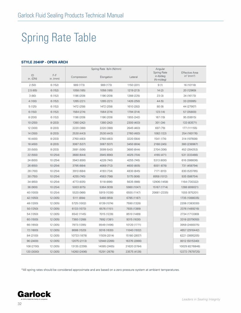
Spring Rate Table
*All spring rates should be considered approximate and are based on a zero pressure system at ambient temperatures.
STYLE 204 - OPEN ARCH

Garlock Fluid Sealing Products Technical Manual
Leaders in Sealing Integrity
31
Spring Rate Table
*All spring rates should be considered approximate and are based on a zero pressure system at ambient temperatures.
Spring Rate lb/in (N/mm) Angular Spring Rate
in-lb/deg(N-m/deg)
Effective Area in2 (mm2)ID
in. (DN)F-F
in. (mm)Compression Elongation Lateral
2 (50) 6 (152) 3440 (602) 3440 (602) 4000 (700) 30 (3) 3 (1963)
2.5 (65) 6 (152) 3680 (644) 3680 (644) 4240 (742) 50 (6) 5 (3318)
3 (80) 6 (152) 4160 (728) 4160 (728) 4480 (784) 82 (9) 7 (5027)
4 (100) 6 (152) 4400 (770) 4400 (770) 4960 (868) 154 (17) 13 (7854)
5 (125) 6 (152) 5120 (896) 5120 (896) 5600 (980) 279 (32) 20 (12272)
6 (150) 6 (152) 5440 (952) 5440 (952) 6240 (1092) 427 (48) 28 (17671)
8 (200) 6 (152) 4160 (728) 4160 (728) 6800 (1190) 581 (66) 50 (31416)
10 (250) 8 (203) 4800 (840) 4800 (840) 8000 (1400) 1047 (118) 79 (49087)
12 (300) 8 (203) 7720 (1351) 7720 (1351) 9200 (1610) 2425 (274) 113 (70686)
14 (350) 8 (203) 8800 (1540) 8800 (1540) 9600 (1680) 3763 (425) 154 (96211)
16 (400) 8 (203) 9600 (1680) 9600 (1680) 11200 (1960) 5362 (606) 201 (125664)
18 (450) 8 (203) 10668 (1867) 10668 (1867) 12000 (2100) 7541 (852) 254 (159043)
20 (500) 8 (203) 10056 (1760) 10780 (1887) 12800 (2240) 9407 (1063) 314 (196350)
22 (550) 10 (254) 12800 (2240) 13720 (2401) 14000 (2450) 14487 (1637) 380 (237583)
24 (600) 10 (254) 13716 (2400) 14708 (2574) 14800 (2590) 18482 (2088) 452 (282743)
26 (650) 10 (254) 13200 (2310) 14154 (2477) 16000 (2800) 20875 (2359) 531 (331831)
28 (700) 10 (254) 13600 (2380) 14583 (2552) 16800 (2940) 24943 (2819) 616 (384845)
30 (750) 10 (254) 14800 (2590) 15870 (2777) 18000 (3150) 31161 (3521) 707 (441786)
34 (850) 10 (254) 16600 (2905) 17800 (3115) 19600 (3430) 44892 (5073) 908 (567450)
36 (900) 10 (254) 17400 (3045) 18658 (3265) 20800 (3640) 52754 (5961) 1018 (636173)
40 (1000) 10 (254) 19200 (3360) 20588 (3603) 22800 (3990) 71866 (8121) 1257 (785398)
42 (1050) 12 (305) 17776 (3111) 19061 (3336) 23600 (4130) 1385 (865901)
48 (1200) 12 (305) 19912 (3485) 21352 (3737) 26400 (4620) 1810 (1130973)
50 (1250) 12 (305) 21332 (3733) 22874 (4003) 27600 (4830) 1963 (1227185)
54 (1350) 12 (305) 22756 (3982) 24401 (4270) 29600 (5180) 2290 (1431388)
60 (1500) 12 (305) 25600 (4480) 27451 (4804) 32400 (5670) 2827 (1767146)
66 (1650) 12 (305) 27732 (4853) 29737 (5204) 35200 (6160) 3421 (2138246)
72 (1800) 12 (305) 30220 (5289) 32405 (5671) 38600 (6720) 4072 (2544690)
84 (2100) 12 (305) 37332 (6533) 40031 (7005) 52800 (9240) 5542 (3463606)
96 (2400) 12 (305) 42000 (7350) 45037 (7881) 56960 (9968) 7238 (4523893)
108 (2700) 12 (305) 45688 (7995) 48991 (8573) 75200 (13160) 9161 (5725553)
120 (3000) 12 (305) 49600 (8680) 53186 (9308) 82000 (14350) 11310 (7068583)
STYLE 204 - FILLED ARCH
Garlock Fluid Sealing Products Technical Manual
Leaders in Sealing Integrity
32
Spring Rate Table
*All spring rates should be considered approximate and are based on a zero pressure system at ambient temperatures.
Spring Rate lb/in (N/mm) Angular Spring Rate
in-lb/deg(N-m/deg)
Effective Area in2 (mm2)ID
in. (DN)F-F
in. (mm)Compression Elongation Lateral
2 (50) 6 (152) 989 (173) 989 (173) 1150 (201) 9 (1) 16 (10118)
2.5 (65) 6 (152) 1058 (185) 1058 (185) 1219 (213) 14 (2) 20 (12969)
3 (80) 6 (152) 1196 (209) 1196 (209) 1288 (225) 23 (3) 24 (16173)
4 (100) 6 (152) 1265 (221) 1265 (221) 1426 (250) 44 (5) 33 (20995)
5 (125) 6 (152) 1472 (258) 1472 (258) 1610 (282) 80 (9) 44 (27907)
6 (150) 6 (152) 1564 (274) 1564 (274) 1794 (314) 123 (14) 57 (35800)
8 (200) 6 (152) 1196 (209) 1196 (209) 1955 (342) 167 (19) 95 (59915)
10 (250) 8 (203) 1380 (242) 1380 (242) 2300 (403) 301 (34) 133 (83571)
12 (300) 8 (203) 2220 (388) 2220 (388) 2645 (463) 697 (79) 177 (111155)
14 (350) 8 (203) 2530 (443) 2530 (443) 2760 (483) 1082 (122) 254 (160176)
16 (400) 8 (203) 2760 (483) 2760 (483) 3220 (564) 1541 (174) 314 (197608)
18 (450) 8 (203) 3067 (537) 3067 (537) 3450 (604) 2168 (245) 380 (238967)
20 (500) 8 (203) 2891 (506) 3099 (542) 3680 (644) 2704 (306) 452 (284253)
22 (550) 10 (254) 3680 (644) 3945 (690) 4025 (704) 4165 (471) 531 (333466)
24 (600) 10 (254) 3943 (690) 4228 (740) 4255 (745) 5313 (600) 616 (386606)
26 (650) 10 (254) 3795 (664) 4069 (712) 4600 (805) 6001 (678) 731 (458794)
28 (700) 10 (254) 3910 (684) 4193 (734) 4830 (845) 7171 (810) 830 (520785)
30 (750) 10 (254) 4255 (745) 4563 (798) 5175 (906) 8958 (1012) 935 (586704)
34 (850) 10 (254) 4773 (835) 5118 (896) 5635 (986) 12906 (1458) 1164 (730322)
36 (900) 10 (254) 5003 (875) 5364 (939) 5980 (1047) 15167 (1714) 1288 (808021)
40 (1000) 10 (254) 5520 (966) 5919 (1036) 6555 (1147) 20661 (2335) 1555 (975201)
42 (1050) 12 (305) 5111 (894) 5480 (959) 6785 (1187) 1735 (1088035)
48 (1200) 12 (305) 5725 (1002) 6139 (1074) 7590 (1328) 2206 (1383030)
50 (1250) 12 (305) 6133 (1073) 6576 (1151) 7935 (1389) 2376 (1489216)
54 (1350) 12 (305) 6542 (1145) 7015 (1228) 8510 (1489) 2734 (1713369)
60 (1500) 12 (305) 7360 (1288) 7892 (1381) 9315 (1630) 3318 (2079050)
66 (1650) 12 (305) 7973 (1395) 8549 (1496) 10120 (1771) 3959 (2480075)
72 (1800) 12 (305) 8688 (1520) 9316 (1630) 11040 (1932) 4657 (2916442)
84 (2100) 12 (305) 10733 (1878) 11509 (2014) 15180 (2657) 6221 (3895205)
96 (2400) 12 (305) 12075 (2113) 12948 (2266) 16376 (2866) 8012 (5015340)
108 (2700) 12 (305) 13135 (2299) 14085 (2465) 21620 (3784) 10029 (6276846)
120 (3000) 12 (305) 14260 (2496) 15291 (2676) 23575 (4126) 12272 (7679725)
STYLE 204HP - OPEN ARCH

Garlock Fluid Sealing Products Technical Manual
Leaders in Sealing Integrity
33
Spring Rate lb/in (N/mm) Angular Spring Rate
in-lb/deg(N-m/deg)
Effective Area in2 (mm2)ID
in. (DN)F-F
in. (mm)Compression Elongation Lateral
2 (50) 6 (152) 3956 (692) 3956 (692) 4600 (805) 35 (4) 3 (1963)
2.5 (65) 6 (152) 4232 (741) 4232 (741) 4876 (853) 646 (73) 5 (3318)
3 (80) 6 (152) 4784 (837) 4784 (837) 5152 (902) 939 (106) 7 (5027)
4 (100) 6 (152) 5060 (886) 5060 (886) 5704 (998) 1590 (180) 13 (7854)
5 (125) 6 (152) 5888 (1030) 5888 (1030) 6440 (1127) 2569 (290) 20 (12272)
6 (150) 6 (152) 6256 (1095) 6256 (1095) 7176 (1256) 3603 (407) 28 (17671)
8 (200) 6 (152) 4784 (837) 4784 (837) 7820 (1369) 4509 (509) 50 (31416)
10 (250) 8 (203) 5520 (966) 5520 (966) 9200 (1610) 7707 (871) 79 (49087)
12 (300) 8 (203) 8878 (1554) 8878 (1554) 10580 (1852) 17664 (1996) 113 (70686)
14 (350) 8 (203) 10120 (1771) 10120 (1771) 11040 (1932) 25964 (2934) 154 (96211)
16 (400) 8 (203) 11040 (1932) 11040 (1932) 12880 (2254) 36224 (4093) 201 (125664)
18 (450) 8 (203) 12268 (2147) 12268 (2147) 13800 (2415) 48177 (5444) 254 (159043)
20 (500) 8 (203) 11564 (2024) 12397 (2169) 14720 (2576) 59501 (6724) 314 (196350)
22 (550) 10 (254) 14720 (2576) 15778 (2761) 16100 (2818) 89359 (10098) 380 (237583)
24 (600) 10 (254) 15773 (2760) 16914 (2960) 17020 (2979) 113357 (12809) 452 (282743)
26 (650) 10 (254) 15180 (2657) 16278 (2849) 18400 (3220) 137573 (15546) 531 (331831)
28 (700) 10 (254) 15640 (2737) 16771 (2935) 19320 (3381) 149573 (16902) 616 (384845)
30 (750) 10 (254) 17020 (2979) 18251 (3194) 20700 (3623) 185146 (20921) 707 (441786)
34 (850) 10 (254) 19090 (3341) 20470 (3582) 22540 (3945) 265720 (30026) 908 (567450)
36 (900) 10 (254) 20010 (3502) 21457 (3755) 23920 (4186) 310077 (35039) 1018 (636173)
40 (1000) 10 (254) 22080 (3864) 23676 (4143) 26220 (4589) 419428 (47395) 1257 (785398)
42 (1050) 12 (305) 20442 (3577) 21920 (3836) 27140 (4750) 1385 (865901)
48 (1200) 12 (305) 22899 (4007) 24554 (4297) 30360 (5313) 1810 (1130973)
50 (1250) 12 (305) 24532 (4293) 26305 (4603) 31740 (5555) 1963 (1227185)
54 (1350) 12 (305) 26169 (4580) 28061 (4911) 34040 (5957) 2290 (1431388)
60 (1500) 12 (305) 29440 (5152) 31569 (5524) 37260 (6521) 2827 (1767146)
66 (1650) 12 (305) 31892 (5581) 34198 (5985) 40480 (7084) 3421 (2138246)
72 (1800) 12 (305) 34753 (6082) 37266 (6521) 44160 (7728) 4072 (2544690)
84 (2100) 12 (305) 42932 (7513) 46036 (8056) 60720 (10626) 5542 (3463606)
96 (2400) 12 (305) 48300 (8453) 51792 (9064) 65504 (11463) 7238 (4523893)
108 (2700) 12 (305) 52541 (9195) 56340 (9859) 86480 (15134) 9161 (5725553)
120 (3000) 12 (305) 57040 (9982) 61164 (10704) 94300 (16503) 11310 (7068583)
Spring Rate Table
*All spring rates should be considered approximate and are based on a zero pressure system at ambient temperatures.
STYLE 204HP - FILLED ARCH

Garlock Fluid Sealing Products Technical Manual
Leaders in Sealing Integrity
34
Spring Rate lb/in (N/mm) Angular Spring Rate
in-lb/deg(N-m/deg)
Effective Area in2 (mm2)ID
in. (DN)F-F
in. (mm)Compression Elongation Lateral
2 (50) 6 (152) 610 (107) 650 (114) 620 (109) 6 (1) 8 (5249)
2.5 (65) 6 (152) 630 (110) 665 (116) 615 (108) 9 (1) 11 (7352)
3 (80) 6 (152) 720 (126) 750 (131) 710 (124) 15 (2) 14 (9808)
4 (100) 6 (152) 765 (134) 870 (152) 825 (144) 30 (3) 22 (13633)
5 (125) 6 (152) 925 (162) 980 (172) 950 (166) 53 (6) 31 (19298)
6 (150) 6 (152) 1150 (201) 1265 (221) 1180 (207) 99 (11) 41 (25944)
8 (200) 6 (152) 1270 (222) 1380 (242) 1230 (215) 193 (22) 67 (42182)
10 (250) 8 (203) 1590 (278) 1725 (302) 1540 (270) 376 (43) 104 (65189)
12 (300) 8 (203) 1910 (334) 2070 (362) 1850 (324) 650 (73) 143 (89780)
14 (350) 8 (203) 1970 (345) 2050 (359) 1890 (331) 877 (99) 189 (118298)
16 (400) 8 (203) 2050 (359) 2160 (378) 1950 (341) 1206 (136) 241 (150743)
18 (450) 8 (203) 2150 (376) 2375 (416) 2210 (387) 1679 (190) 299 (187115)
20 (500) 8 (203) 2350 (411) 2470 (432) 2380 (417) 2155 (244) 363 (227413)
22 (550) 10 (254) 2550 (446) 2650 (464) 2575 (451) 2798 (316) 452 (283498)
24 (600) 10 (254) 2750 (481) 2830 (495) 2790 (488) 3556 (402) 531 (332648)
26 (650) 10 (254) 2900 (508) 3025 (529) 2980 (522) 4461 (504) 616 (385725)
28 (700) 10 (254) 3185 (557) 3275 (573) 3100 (543) 5601 (633) 707 (442729)
30 (750) 10 (254) 3200 (560) 3450 (604) 3120 (546) 6774 (765) 804 (503661)
34 (850) 10 (254) 3600 (630) 3845 (673) 3625 (634) 9697 (1096) 1018 (637304)
36 (900) 10 (254) 4250 (744) 4500 (788) 4300 (753) 12723 (1438) 1134 (710016)
40 (1000) 10 (254) 4380 (767) 4700 (823) 4565 (799) 16406 (1854) 1385 (867221)
42 (1050) 12 (305) 4550 (796) 4870 (852) 5050 (884) 18742 (2118) 1521 (951715)
48 (1200) 12 (305) 4870 (852) 5270 (922) 5930 (1038) 26490 (2993) 1963 (1228756)
50 (1250) 12 (305)
Contact Garlock for Engineering Evaluation
2124 (1328957)
54 (1350) 12 (305) 2463 (1541140)
60 (1500) 12 (305) 3019 (1888867)
66 (1650) 12 (305) 3632 (2271937)
72 (1800) 12 (305) 4301 (2690350)
84 (2100) 12 (305) 5809 (3633205)
96 (2400) 12 (305) 7543 (4717432)
108 (2700) 12 (305) 9503 (5943030)
120 (3000) 12 (305) 11690 (7310000)
STYLE 206 EZ-FLO® ARCH
Spring Rate Table
*All spring rates should be considered approximate and are based on a zero pressure system at ambient temperatures.

Garlock Fluid Sealing Products Technical Manual
Leaders in Sealing Integrity
35
Expansion Joint SurveyGarlock Sealing Technologies EJ Survey Sheet DC-319 05-16 Page #:
Date: Garlock Tag #:Customer Name: Customer Location Description:Plant Location:Contacts at Plant:Distributor: Contact:FSR: Survey by:
Evaluation:
129 3
FF 6FF Lat. FF
Lat. Orient. Lat. Other Notes:Orient. Orient. N
W ES
FF FF
Lat. Lat.Orient. Orient.
Temperature:
Application:FF FF
Lat. FF Lat.Orient. Lat. Orient.
Orient.
Media:
Type of Arch: Ez-Flo Cracking at Base of FlangeCracking at Base of ArchFabric Exposed and TornBallooning Pressure:Delamination of Cover Vacuum:
Type of Rings: Arch TwistedO.D. of Flange Delaminated
Condition of Rings: PaintedOvercompressedOverelongated Manfacturer:Bolt InterferenceBolts in Backwards Style Number:
ANSI 150# Other Soft & SpongyLeaking
Description:ODDist. Between Bolts# Holes Hole Dia.
CU's being used: Yes No
# Rods / Set:
Vertical Pipe RunHorizontal Pipe RunAngular Pipe Run
Retaining Ring informaiton
Arch Information
# of archesAbrupt
Control Unit Information
Drilling Information
Non-Standard Details
Tapers
Concentric taper
Eccentric taper
The flanges on concentric
tapers share a center line
Eccentric tapers have an edge that is parallel
to the connecting pipe
Recommendation:
Currently Using
Visual Inspection
Vertical Run
Use clock positions
Use compass
Measurements
S.T.A.M.P.
View looking from _________________ (stationary / front flange)
to ___________________ (moving / back flange)
Orientation Directions
Horizontal run
Pipe ID ____________

Garlock Fluid Sealing Products Technical Manual
Leaders in Sealing Integrity
36
Notes:


Tel: 1-877-GARLOCK / 315.597.4811 Fax: 800.543.0598 / 315.597.3216www.garlock.com
GARLOCKan EnPro Industries family of companies
GarlockGPTGarlock AustraliaGarlock de Canada, LTD
Garlock ChinaGarlock SingaporeGarlock GermanyGarlock India Private Limited
Garlock de Mexico, S.A. De C.V.Garlock New ZealandGarlock Great Britain LimitedGarlock Middle East
EJ 9-15_09.14.2018