garmin g1000 ground school - microsoft...
TRANSCRIPT

Garmin G1000 Ground
School
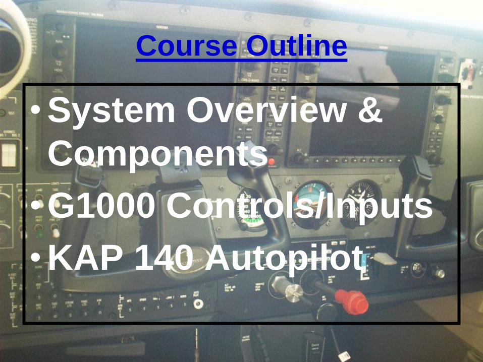
Course Outline
• System Overview &
Components
• G1000 Controls/Inputs
• KAP 140 Autopilot
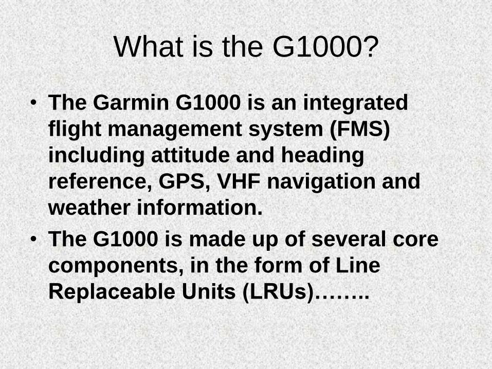
What is the G1000?
• The Garmin G1000 is an integrated
flight management system (FMS)
including attitude and heading
reference, GPS, VHF navigation and
weather information.
• The G1000 is made up of several core
components, in the form of Line
Replaceable Units (LRUs)……..
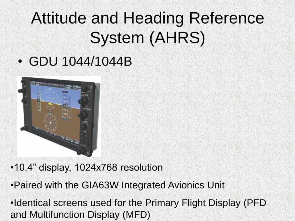
Attitude and Heading Reference
System (AHRS)
• GDU 1044/1044B
•10.4” display, 1024x768 resolution
•Paired with the GIA63W Integrated Avionics Unit
•Identical screens used for the Primary Flight Display (PFD
and Multifunction Display (MFD)
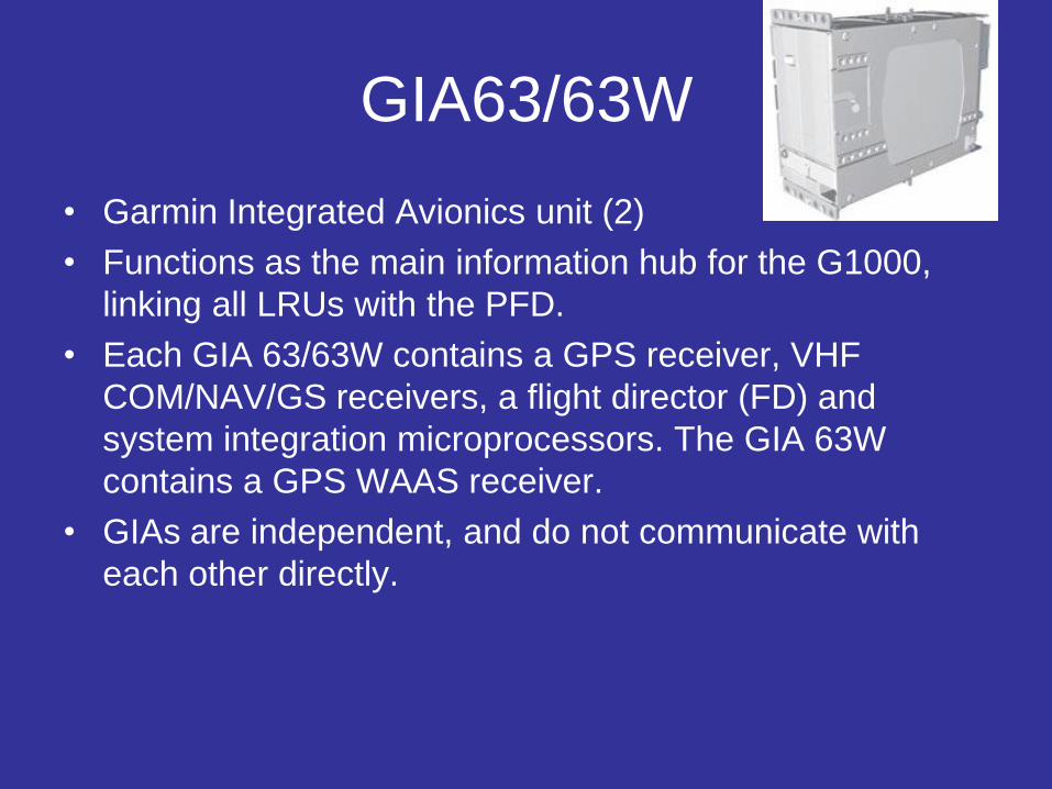
GIA63/63W
• Garmin Integrated Avionics unit (2)
• Functions as the main information hub for the G1000,
linking all LRUs with the PFD.
• Each GIA 63/63W contains a GPS receiver, VHF
COM/NAV/GS receivers, a flight director (FD) and
system integration microprocessors. The GIA 63W
contains a GPS WAAS receiver.
• GIAs are independent, and do not communicate with
each other directly.
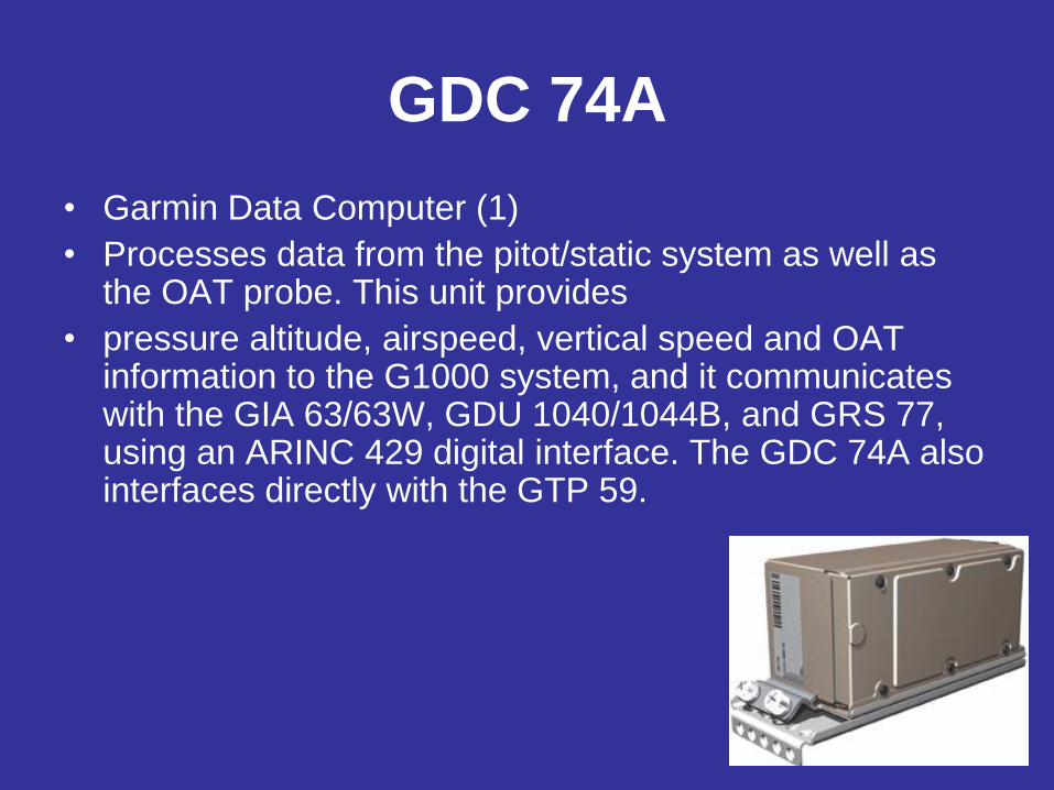
GDC 74A
• Garmin Data Computer (1)
• Processes data from the pitot/static system as well as the OAT probe. This unit provides
• pressure altitude, airspeed, vertical speed and OAT information to the G1000 system, and it communicates with the GIA 63/63W, GDU 1040/1044B, and GRS 77, using an ARINC 429 digital interface. The GDC 74A also interfaces directly with the GTP 59.
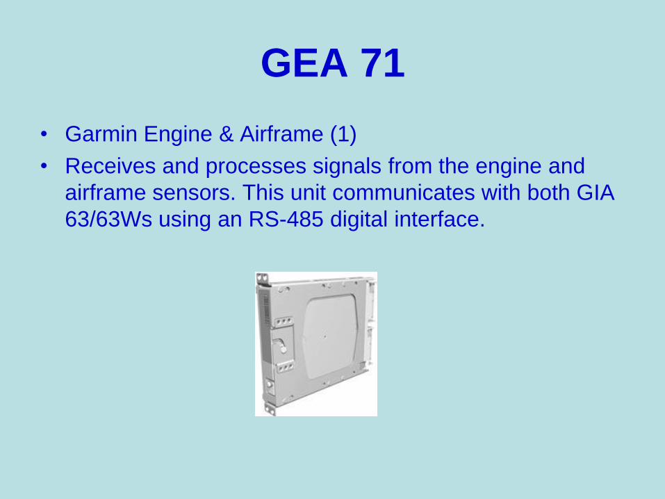
GEA 71
• Garmin Engine & Airframe (1)
• Receives and processes signals from the engine and
airframe sensors. This unit communicates with both GIA
63/63Ws using an RS-485 digital interface.
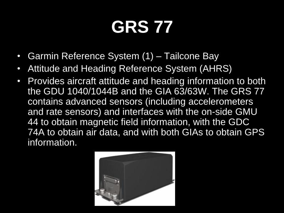
GRS 77
• Garmin Reference System (1) – Tailcone Bay
• Attitude and Heading Reference System (AHRS)
• Provides aircraft attitude and heading information to both the GDU 1040/1044B and the GIA 63/63W. The GRS 77 contains advanced sensors (including accelerometers and rate sensors) and interfaces with the on-side GMU 44 to obtain magnetic field information, with the GDC 74A to obtain air data, and with both GIAs to obtain GPS information.
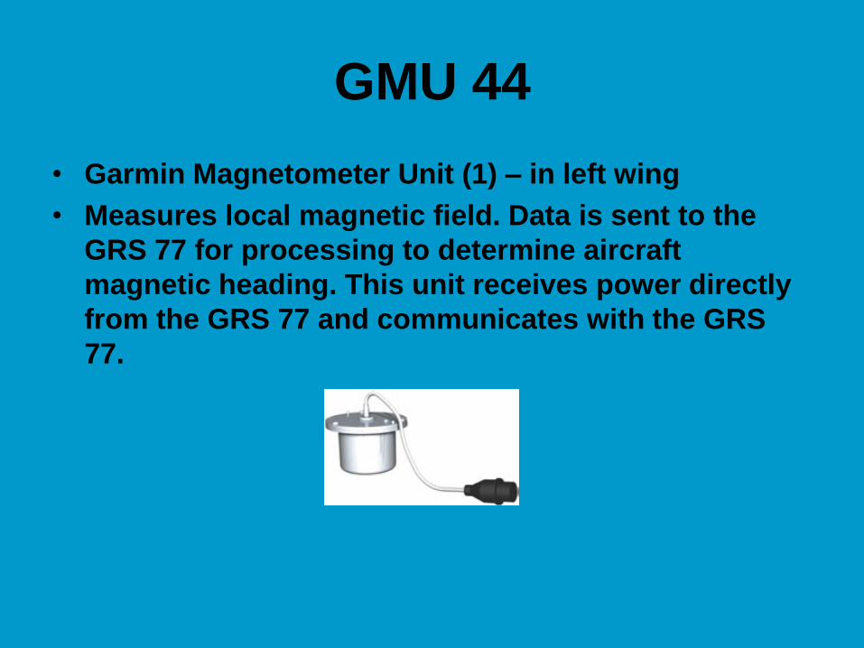
GMU 44
• Garmin Magnetometer Unit (1) – in left wing
• Measures local magnetic field. Data is sent to the
GRS 77 for processing to determine aircraft
magnetic heading. This unit receives power directly
from the GRS 77 and communicates with the GRS
77.

GMA 1347
• Garmin Marker Beacon/Audio Panel (1)
• Integrates NAV/COM digital audio, intercom system and marker beacon controls. The GMA 1347 also controls manual display reversionary mode (red DISPLAY BACKUP button) and is installed between the MFD and the PFD. The GMA 1347 communicates with both GIA 63/63Ws.
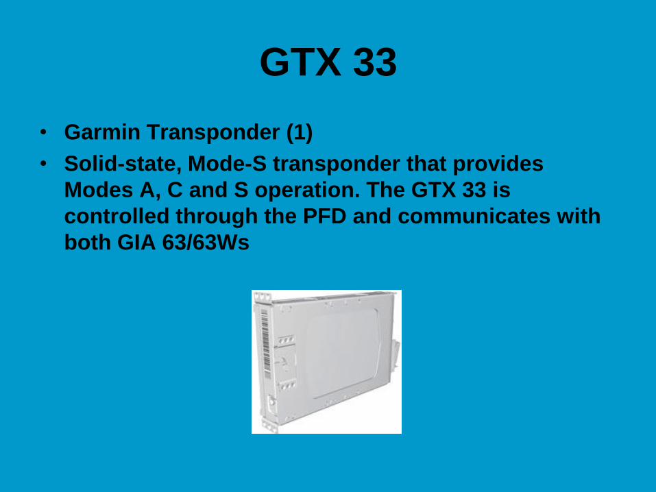
GTX 33
• Garmin Transponder (1)
• Solid-state, Mode-S transponder that provides
Modes A, C and S operation. The GTX 33 is
controlled through the PFD and communicates with
both GIA 63/63Ws
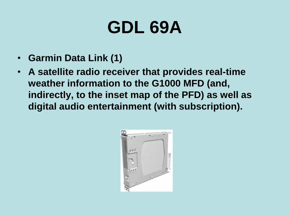
GDL 69A
• Garmin Data Link (1)
• A satellite radio receiver that provides real-time
weather information to the G1000 MFD (and,
indirectly, to the inset map of the PFD) as well as
digital audio entertainment (with subscription).
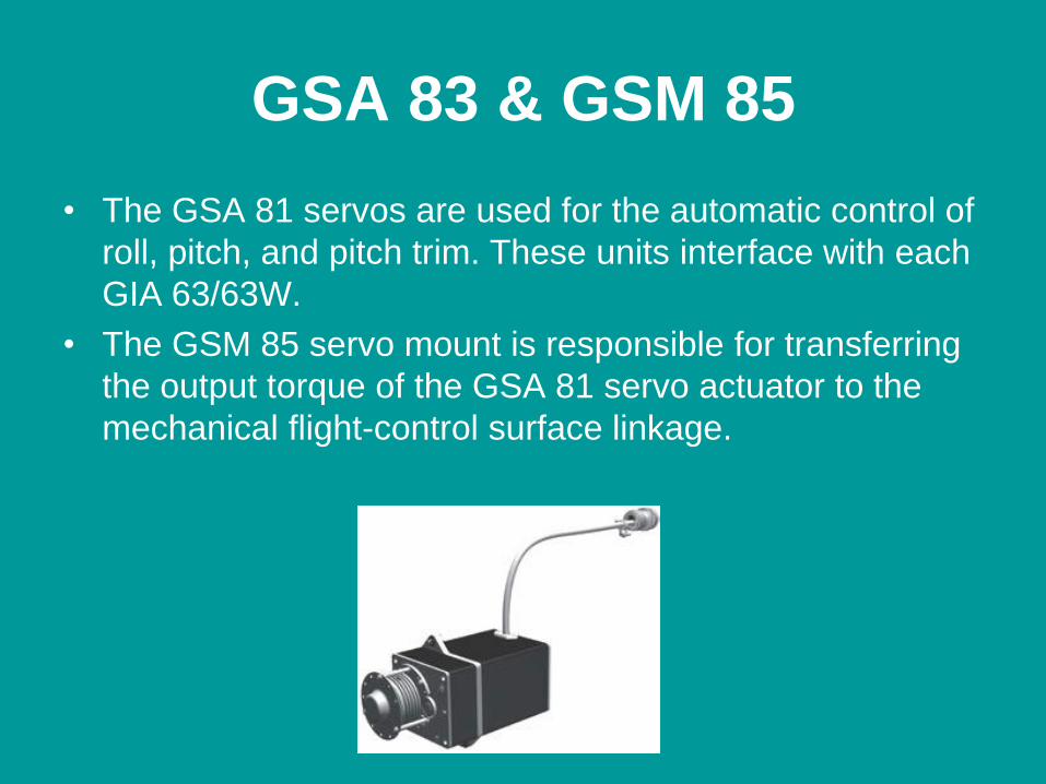
GSA 83 & GSM 85
• The GSA 81 servos are used for the automatic control of
roll, pitch, and pitch trim. These units interface with each
GIA 63/63W.
• The GSM 85 servo mount is responsible for transferring
the output torque of the GSA 81 servo actuator to the
mechanical flight-control surface linkage.
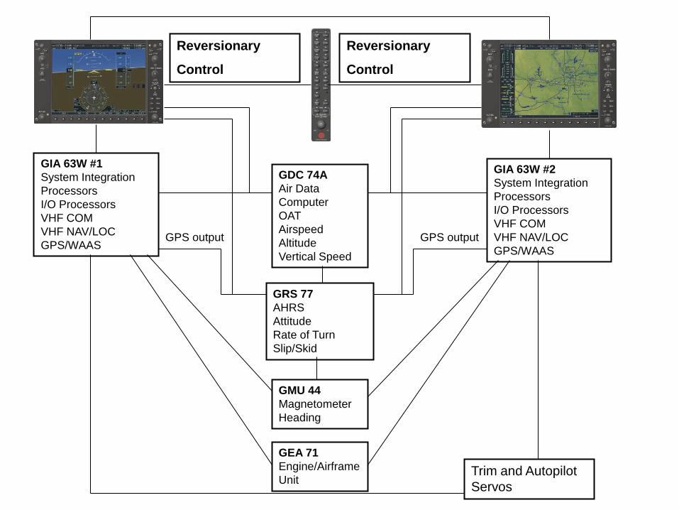
GIA 63W #1
System Integration
Processors
I/O Processors
VHF COM
VHF NAV/LOC
GPS/WAAS
Reversionary
Control
Reversionary
Control
GIA 63W #2
System Integration
Processors
I/O Processors
VHF COM
VHF NAV/LOC
GPS/WAAS
GDC 74A
Air Data
Computer
OAT
Airspeed
Altitude
Vertical Speed
GRS 77
AHRS
Attitude
Rate of Turn
Slip/Skid
GPS output GPS output
GMU 44
Magnetometer
Heading
GEA 71
Engine/Airframe
Unit Trim and Autopilot
Servos
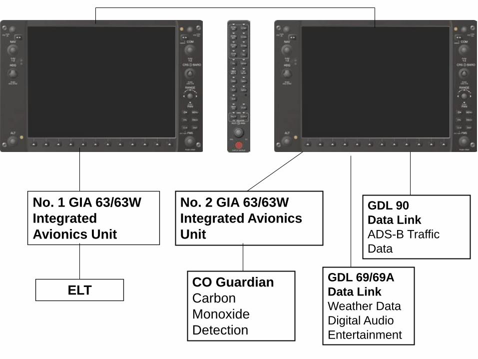
No. 1 GIA 63/63W
Integrated
Avionics Unit
ELT
No. 2 GIA 63/63W
Integrated Avionics
Unit
CO Guardian
Carbon
Monoxide
Detection
GDL 69/69A
Data Link
Weather Data
Digital Audio
Entertainment
GDL 90
Data Link
ADS-B Traffic
Data

G1000 Inputs
and Controls •PFD
•MFD
•Audio Panel
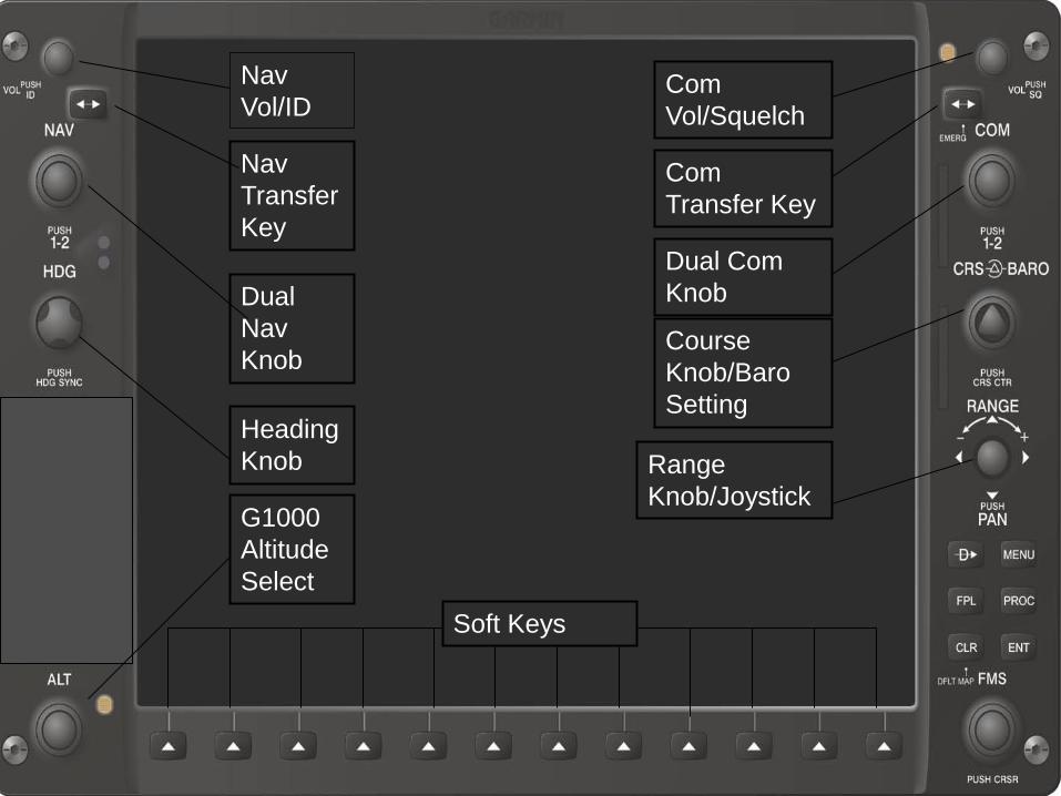
Nav
Vol/ID
Nav
Transfer
Key
Dual
Nav
Knob
Heading
Knob
G1000
Altitude
Select
Soft Keys
Com
Vol/Squelch
Com
Transfer Key
Dual Com
Knob
Course
Knob/Baro
Setting
Range
Knob/Joystick
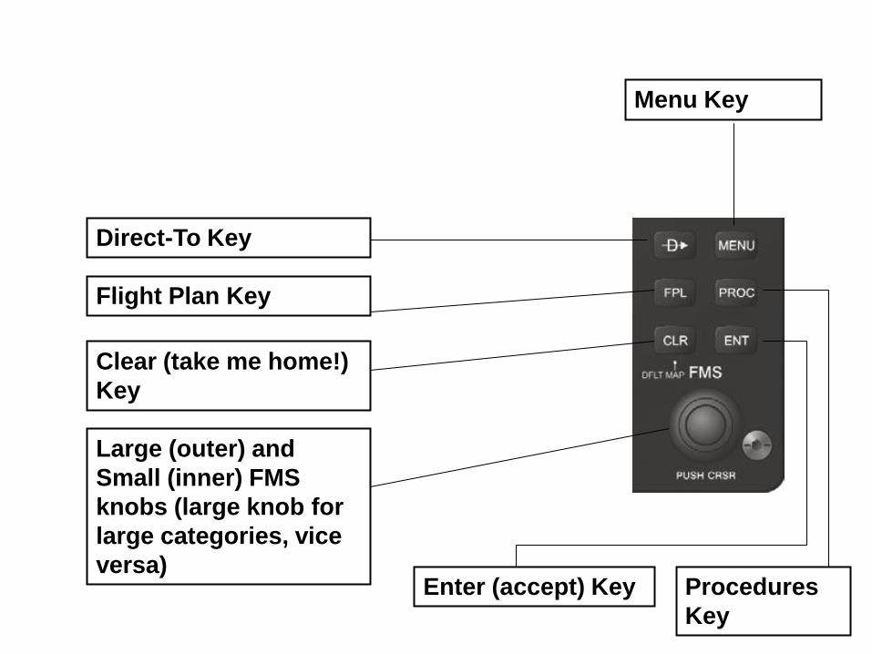
Direct-To Key
Menu Key
Flight Plan Key
Clear (take me home!)
Key
Procedures
Key
Enter (accept) Key
Large (outer) and
Small (inner) FMS
knobs (large knob for
large categories, vice
versa)
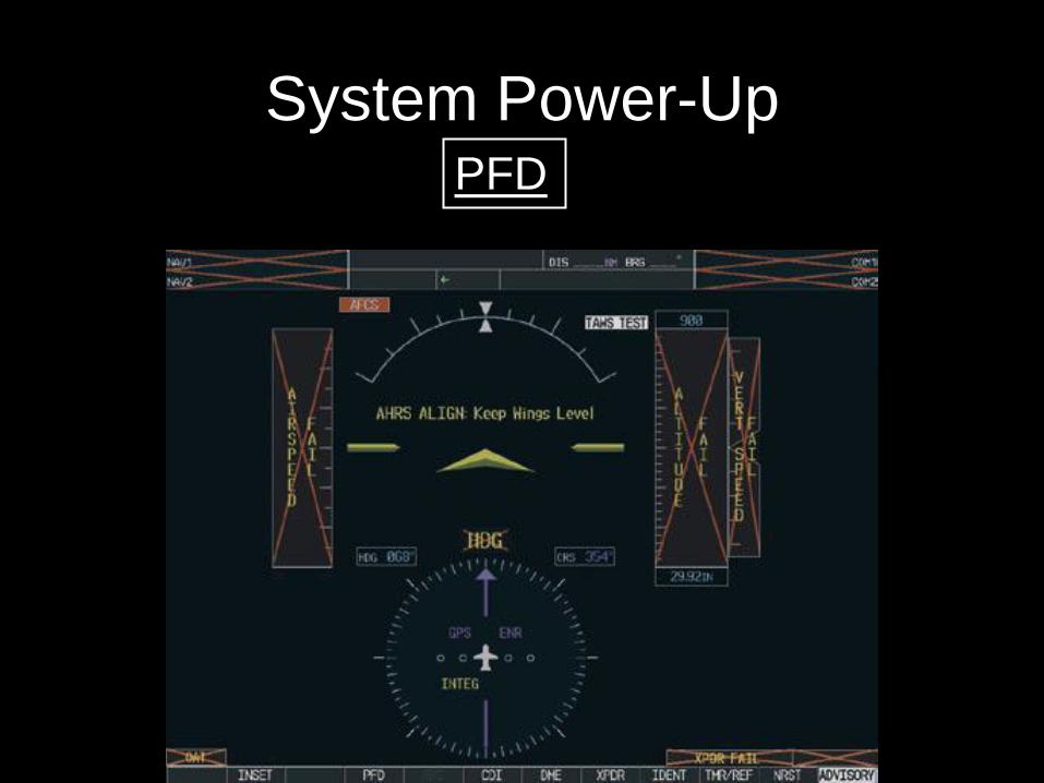
System Power-Up PFD
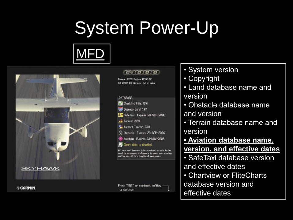
System Power-Up
MFD • System version
• Copyright
• Land database name and
version
• Obstacle database name
and version
• Terrain database name and
version
• Aviation database name,
version, and effective dates
• SafeTaxi database version
and effective dates
• Chartview or FliteCharts
database version and
effective dates
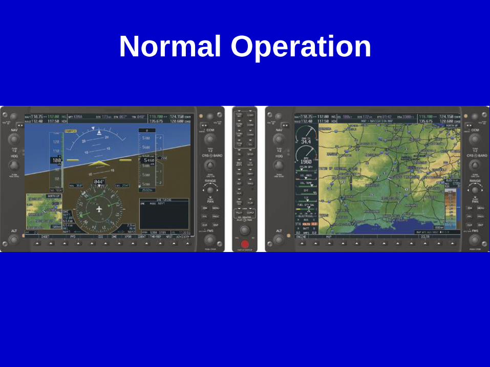
Normal Operation
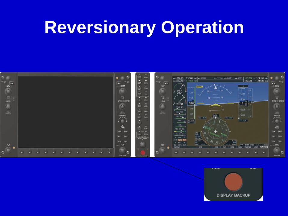
Reversionary Operation
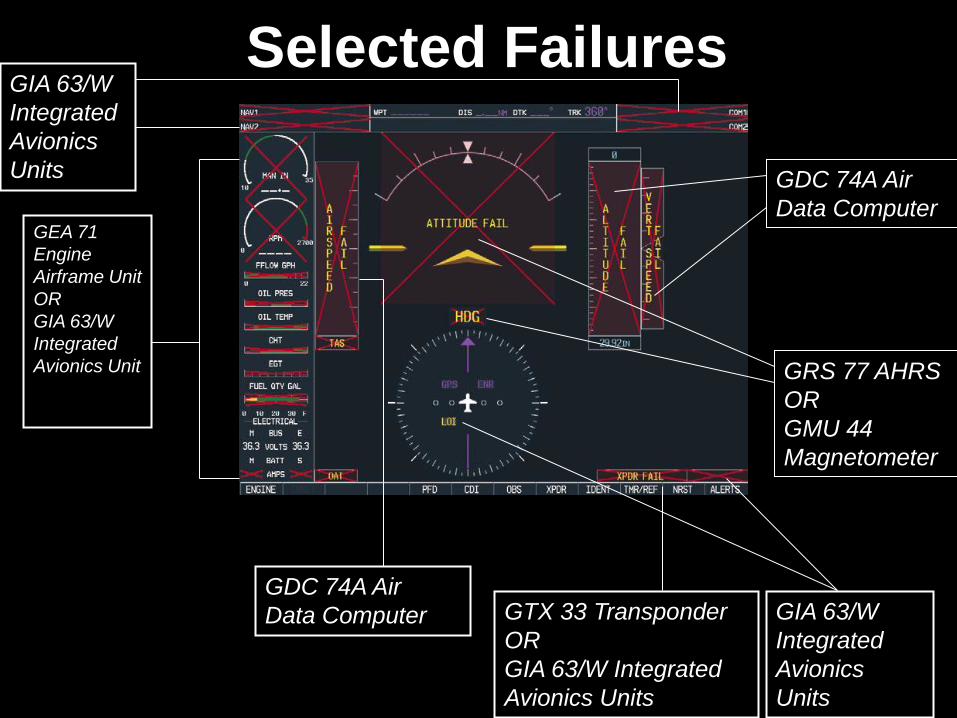
Selected Failures GIA 63/W
Integrated
Avionics
Units
GEA 71
Engine
Airframe Unit
OR
GIA 63/W
Integrated
Avionics Unit
GDC 74A Air
Data Computer GTX 33 Transponder
OR
GIA 63/W Integrated
Avionics Units
GIA 63/W
Integrated
Avionics
Units
GRS 77 AHRS
OR
GMU 44
Magnetometer
GDC 74A Air
Data Computer
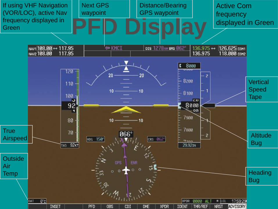
PFD Display
Outside
Air
Temp
Active Com
frequency
displayed in Green
Next GPS
waypoint
Distance/Bearing
GPS waypoint
If using VHF Navigation
(VOR/LOC), active Nav
frequency displayed in
Green
True
Airspeed Altitude
Bug
Vertical
Speed
Tape
Heading
Bug
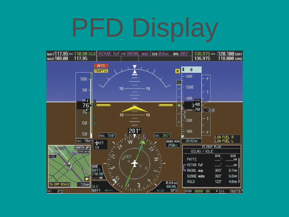
PFD Display
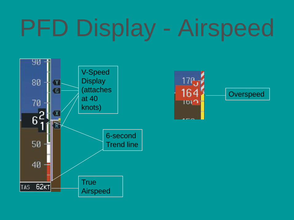
PFD Display - Airspeed
True
Airspeed
V-Speed
Display
(attaches
at 40
knots)
6-second
Trend line
Overspeed
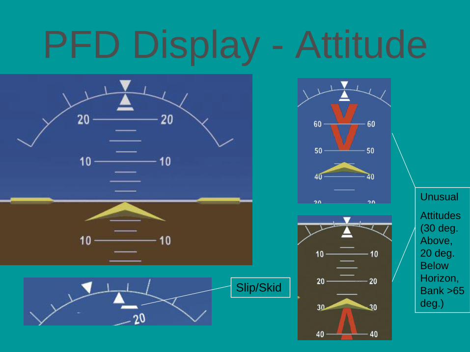
PFD Display - Attitude
Unusual
Attitudes
(30 deg.
Above,
20 deg.
Below
Horizon,
Bank >65
deg.)
Slip/Skid
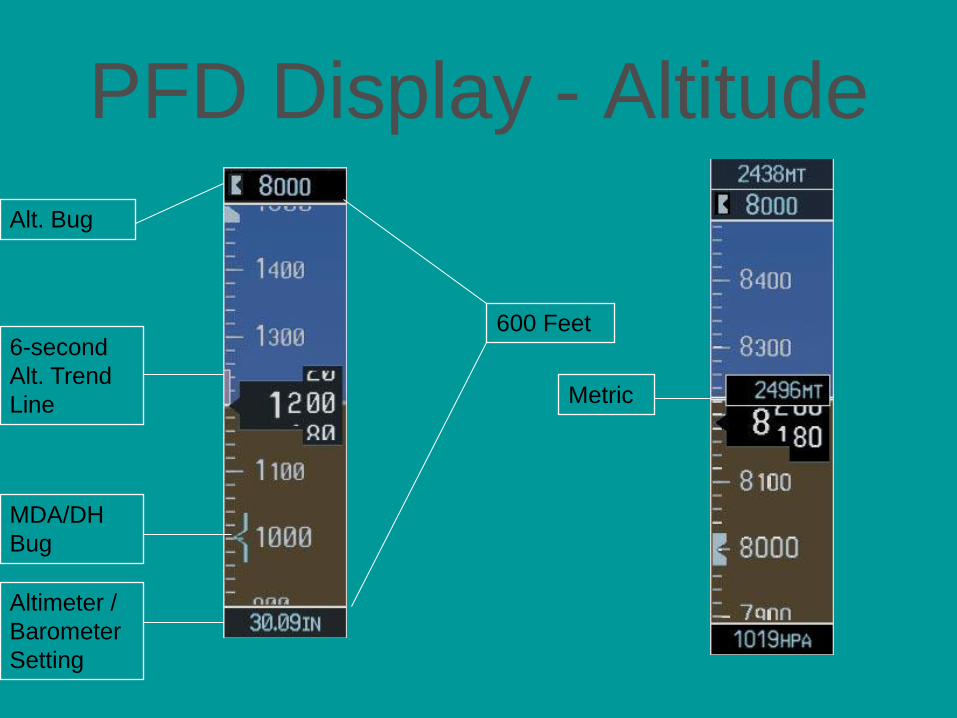
PFD Display - Altitude
Alt. Bug
6-second
Alt. Trend
Line
MDA/DH
Bug
Altimeter /
Barometer
Setting
Metric
600 Feet
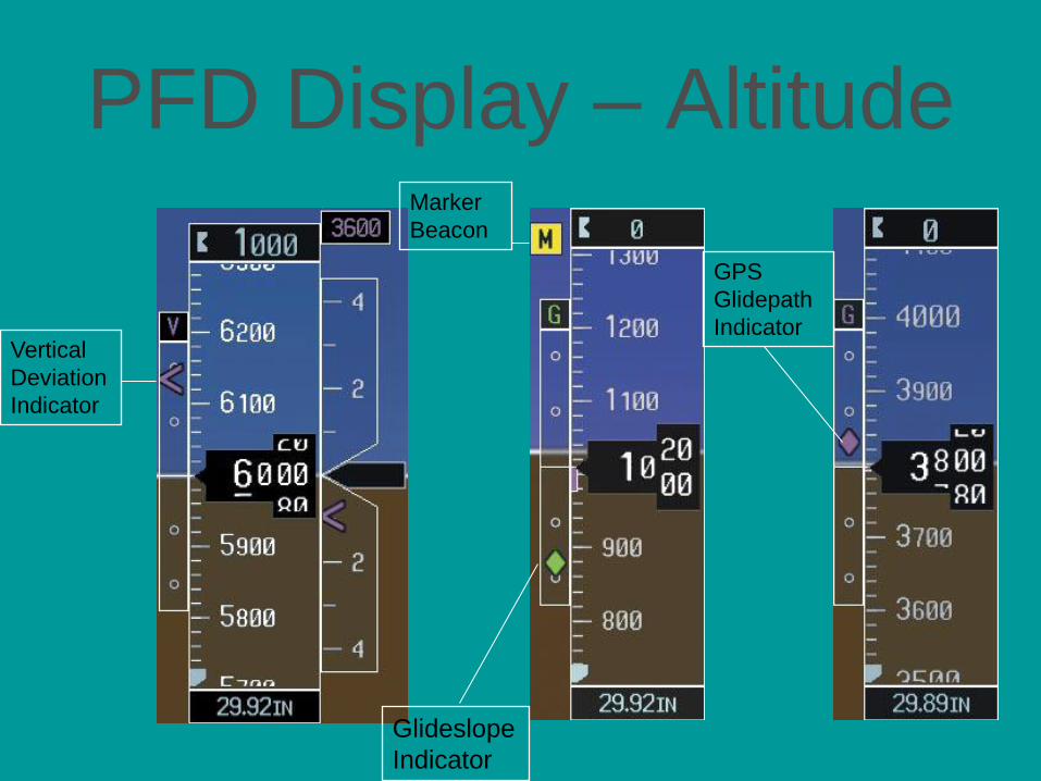
PFD Display – Altitude
Vertical
Deviation
Indicator
Glideslope
Indicator
Marker
Beacon
GPS
Glidepath
Indicator
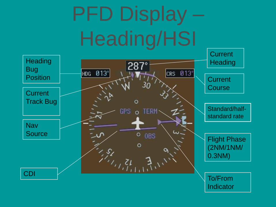
PFD Display –
Heading/HSI Heading
Bug
Position
Current
Heading
Current
Course
Standard/half-
standard rate
Current
Track Bug
CDI To/From
Indicator
Nav
Source Flight Phase
(2NM/1NM/
0.3NM)
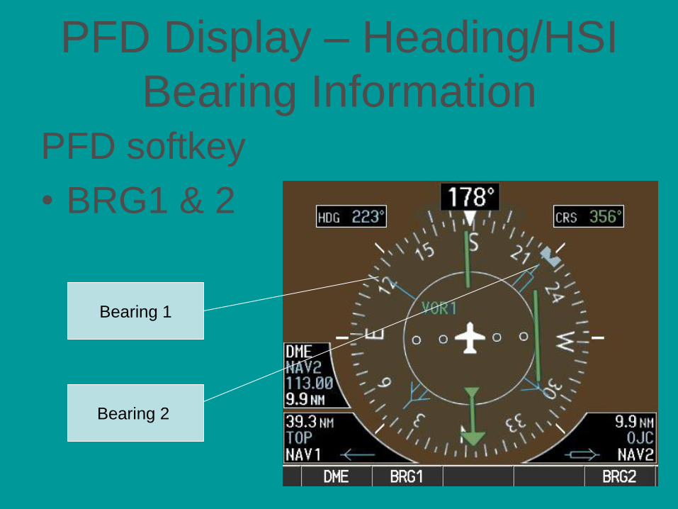
PFD Display – Heading/HSI
Bearing Information PFD softkey
• BRG1 & 2
Bearing 1
Bearing 2
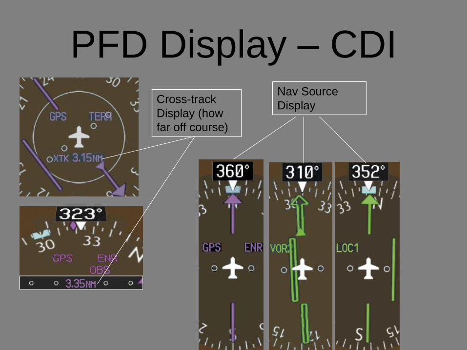
PFD Display – CDI Cross-track
Display (how
far off course)
Nav Source
Display
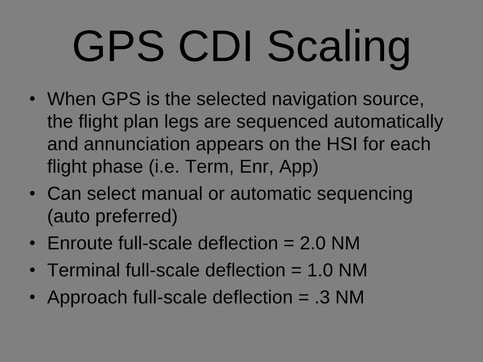
GPS CDI Scaling • When GPS is the selected navigation source,
the flight plan legs are sequenced automatically
and annunciation appears on the HSI for each
flight phase (i.e. Term, Enr, App)
• Can select manual or automatic sequencing
(auto preferred)
• Enroute full-scale deflection = 2.0 NM
• Terminal full-scale deflection = 1.0 NM
• Approach full-scale deflection = .3 NM
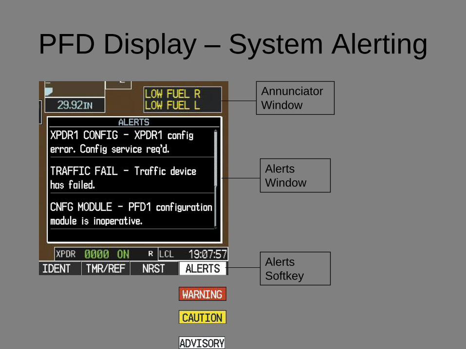
PFD Display – System Alerting
Alerts
Softkey
Alerts
Window
Annunciator
Window
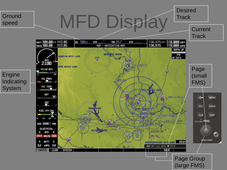
MFD Display
Engine
Indicating
System
Ground
speed
Desired
Track
Current
Track
Page Group
(large FMS)
Page
(small
FMS)
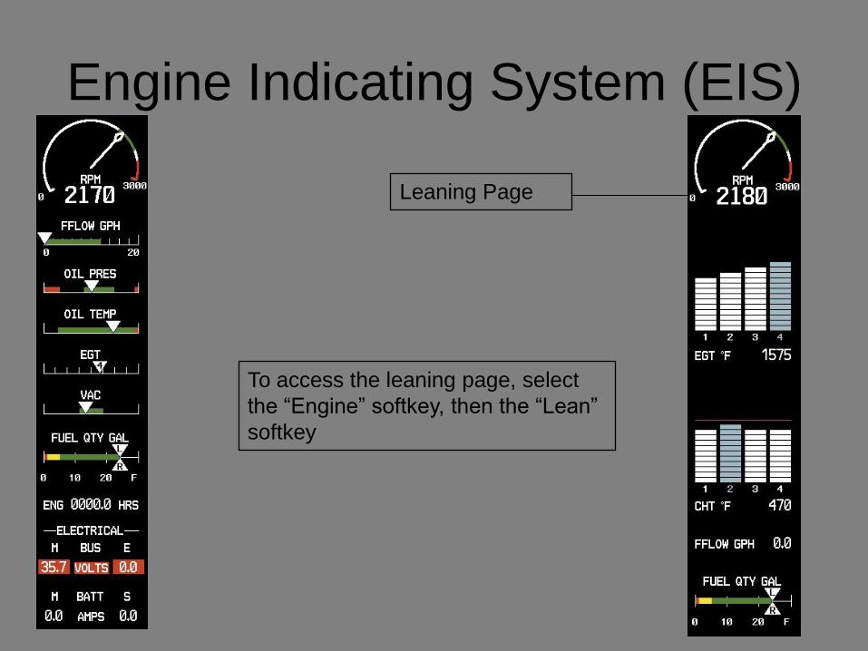
Engine Indicating System (EIS)
Leaning Page
To access the leaning page, select
the “Engine” softkey, then the “Lean”
softkey
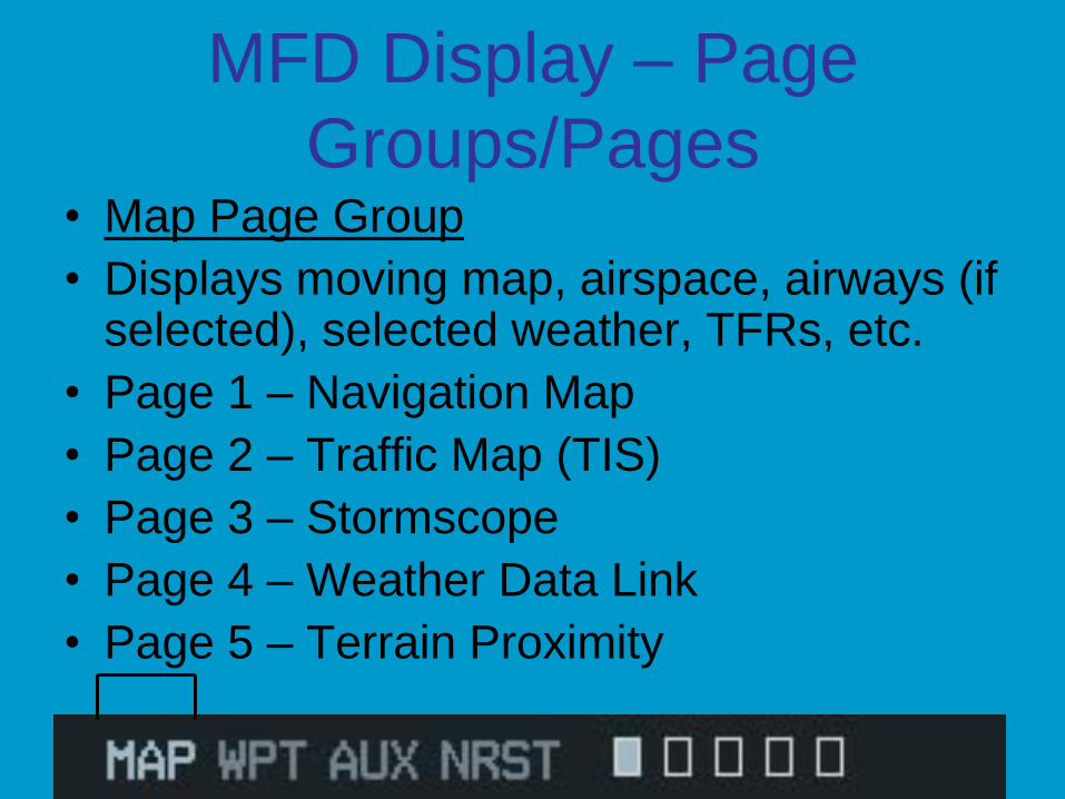
MFD Display – Page
Groups/Pages • Map Page Group
• Displays moving map, airspace, airways (if selected), selected weather, TFRs, etc.
• Page 1 – Navigation Map
• Page 2 – Traffic Map (TIS)
• Page 3 – Stormscope
• Page 4 – Weather Data Link
• Page 5 – Terrain Proximity
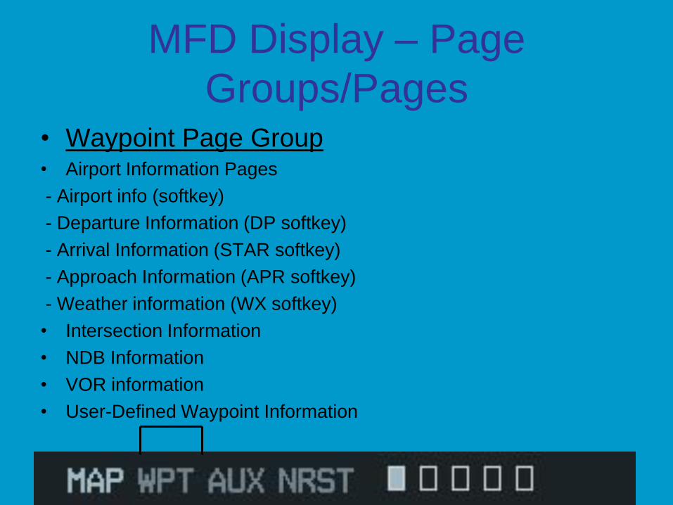
MFD Display – Page
Groups/Pages • Waypoint Page Group • Airport Information Pages
- Airport info (softkey)
- Departure Information (DP softkey)
- Arrival Information (STAR softkey)
- Approach Information (APR softkey)
- Weather information (WX softkey)
• Intersection Information
• NDB Information
• VOR information
• User-Defined Waypoint Information

MFD Display – Page
Groups/Pages • AUX Page Group
• Trip Planning
• Utility
• GPS Status
• System Setup
• XM Satellite Pages (XM info: INFO softkey, XM Radio: RADIO softkey)
• System Status
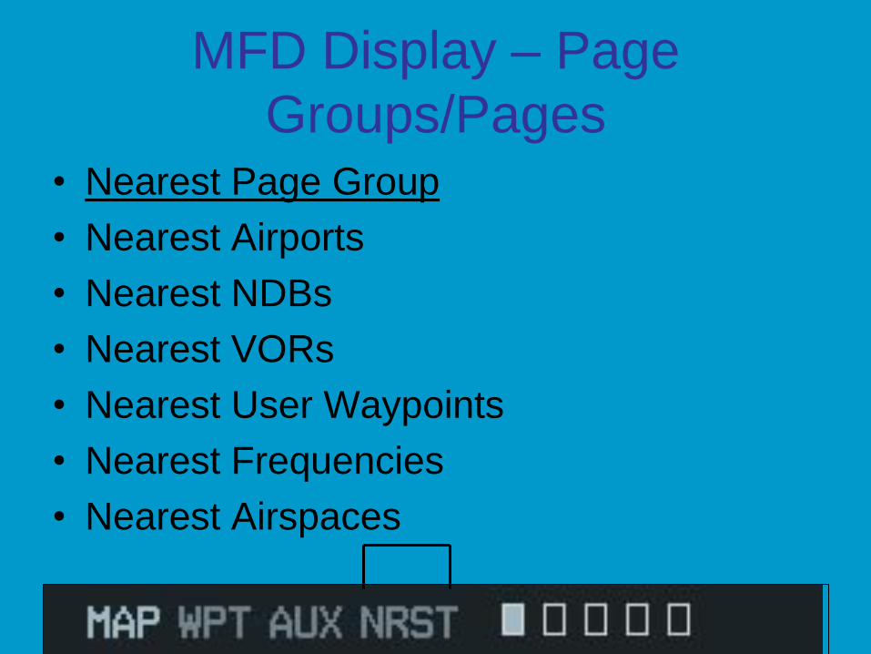
MFD Display – Page
Groups/Pages • Nearest Page Group
• Nearest Airports
• Nearest NDBs
• Nearest VORs
• Nearest User Waypoints
• Nearest Frequencies
• Nearest Airspaces
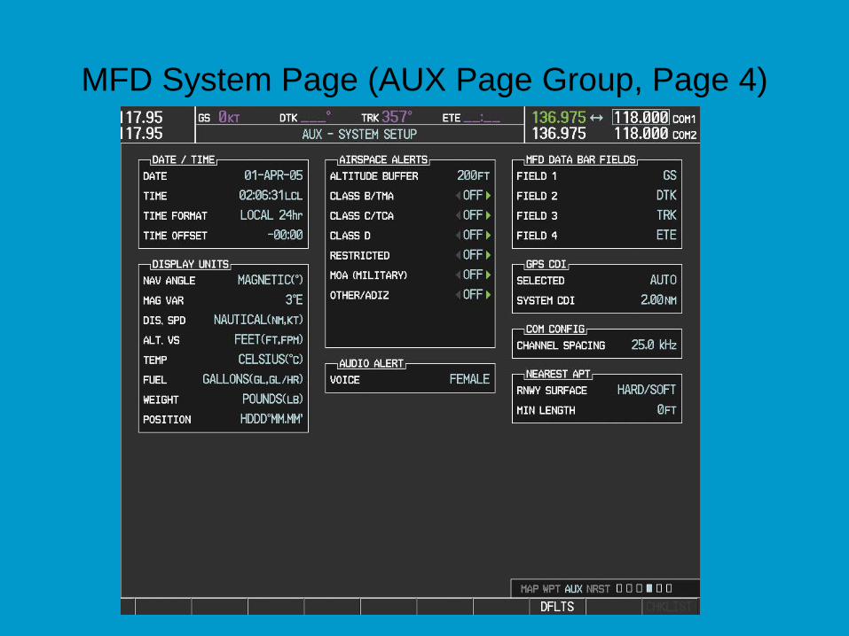
MFD System Page (AUX Page Group, Page 4)
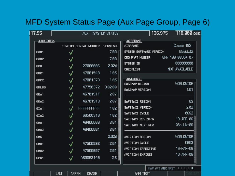
MFD System Status Page (Aux Page Group, Page 6)
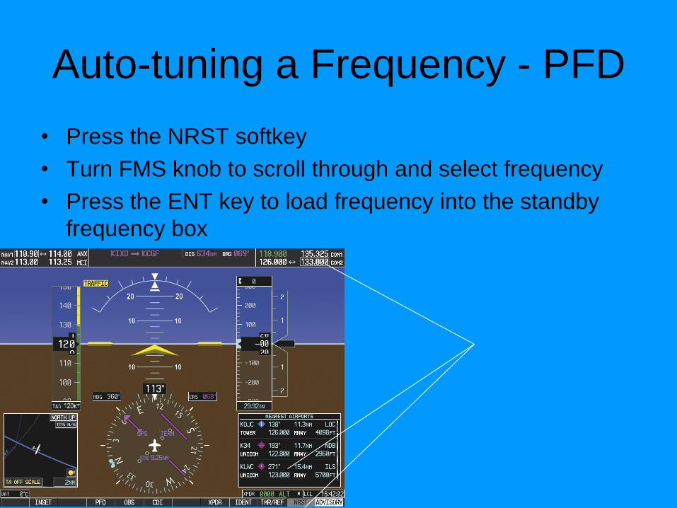
Auto-tuning a Frequency - PFD
• Press the NRST softkey
• Turn FMS knob to scroll through and select frequency
• Press the ENT key to load frequency into the standby
frequency box
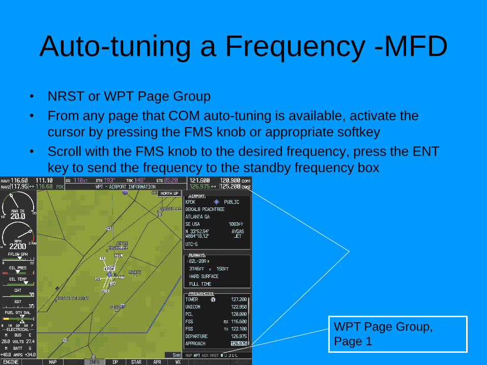
Auto-tuning a Frequency -MFD
• NRST or WPT Page Group
• From any page that COM auto-tuning is available, activate the
cursor by pressing the FMS knob or appropriate softkey
• Scroll with the FMS knob to the desired frequency, press the ENT
key to send the frequency to the standby frequency box
WPT Page Group,
Page 1

AUDIO PANEL
CONTROLS
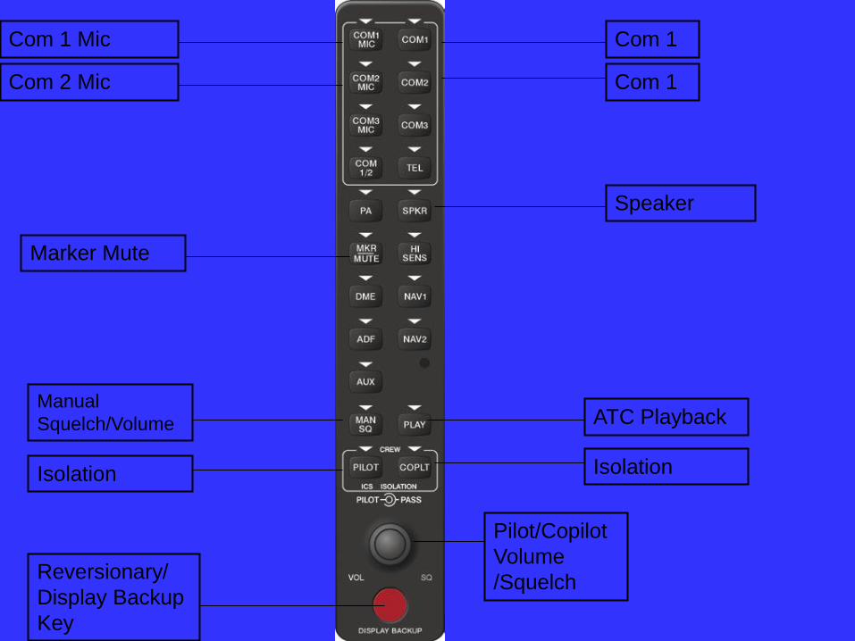
Com 1 Mic
Com 2 Mic
Com 1
Com 1
Speaker
Marker Mute
Manual
Squelch/Volume
Isolation Isolation
Pilot/Copilot
Volume
/Squelch Reversionary/
Display Backup
Key
ATC Playback
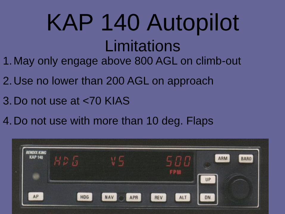
KAP 140 Autopilot Limitations
1.May only engage above 800 AGL on climb-out
2.Use no lower than 200 AGL on approach
3.Do not use at <70 KIAS
4.Do not use with more than 10 deg. Flaps
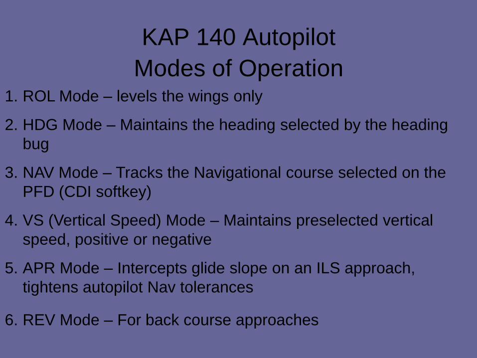
KAP 140 Autopilot
Modes of Operation
1. ROL Mode – levels the wings only
2. HDG Mode – Maintains the heading selected by the heading
bug
3. NAV Mode – Tracks the Navigational course selected on the
PFD (CDI softkey)
4. VS (Vertical Speed) Mode – Maintains preselected vertical
speed, positive or negative
5. APR Mode – Intercepts glide slope on an ILS approach,
tightens autopilot Nav tolerances
6. REV Mode – For back course approaches
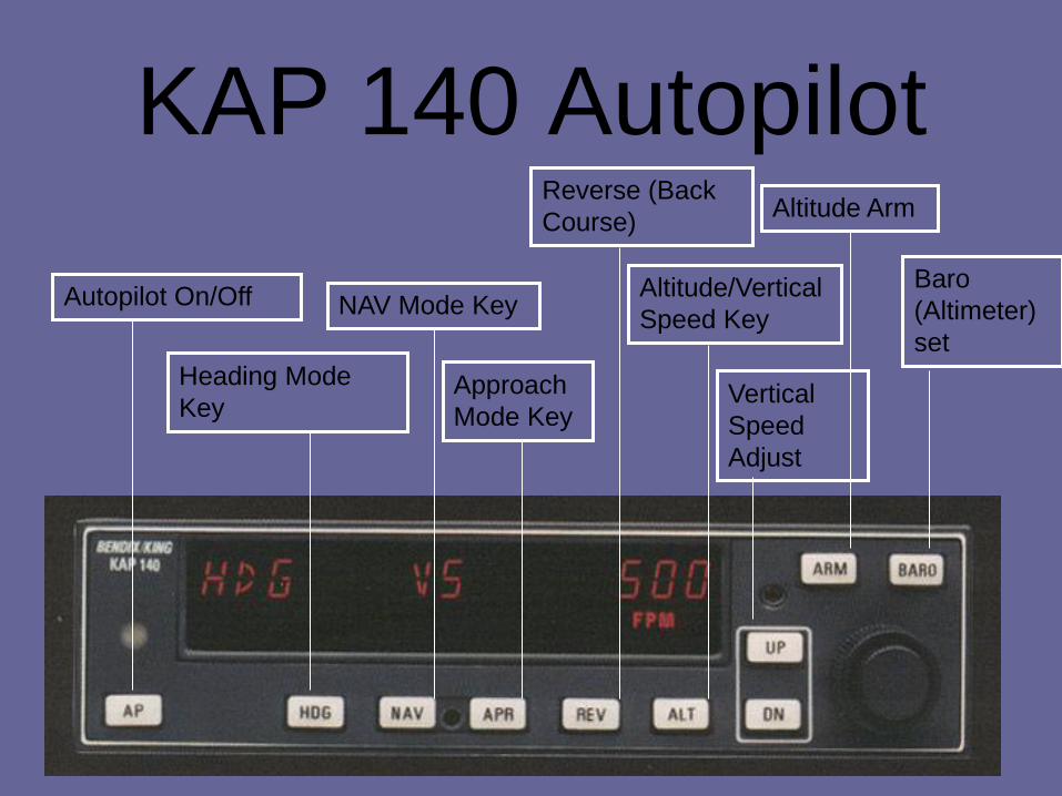
KAP 140 Autopilot
Autopilot On/Off
Heading Mode
Key
NAV Mode Key
Approach
Mode Key
Reverse (Back
Course)
Altitude/Vertical
Speed Key
Vertical
Speed
Adjust
Altitude Arm
Baro
(Altimeter)
set
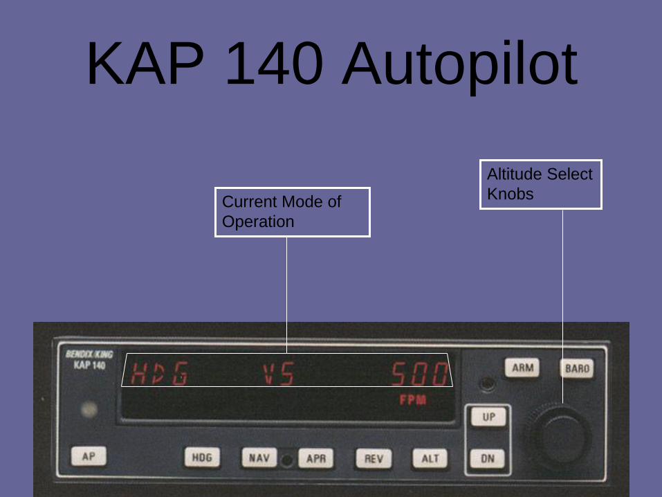
KAP 140 Autopilot
Altitude Select
Knobs Current Mode of
Operation
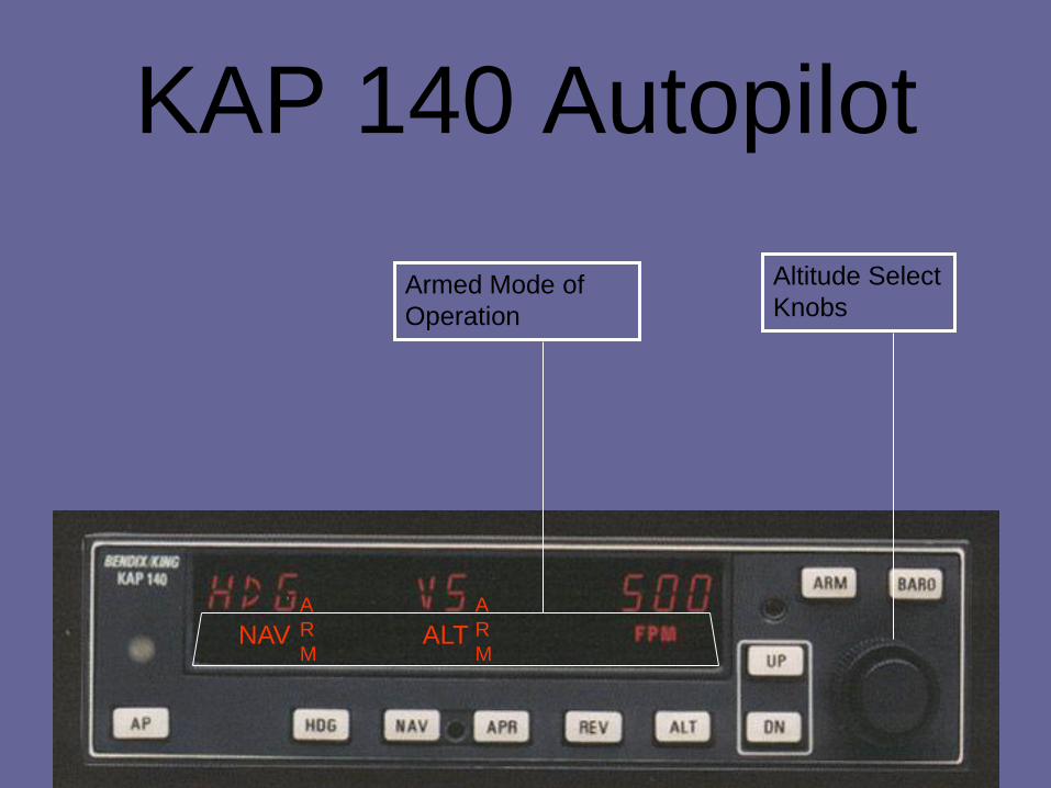
KAP 140 Autopilot
Altitude Select
Knobs Armed Mode of
Operation
NAV
A
R
M
A
R
M ALT
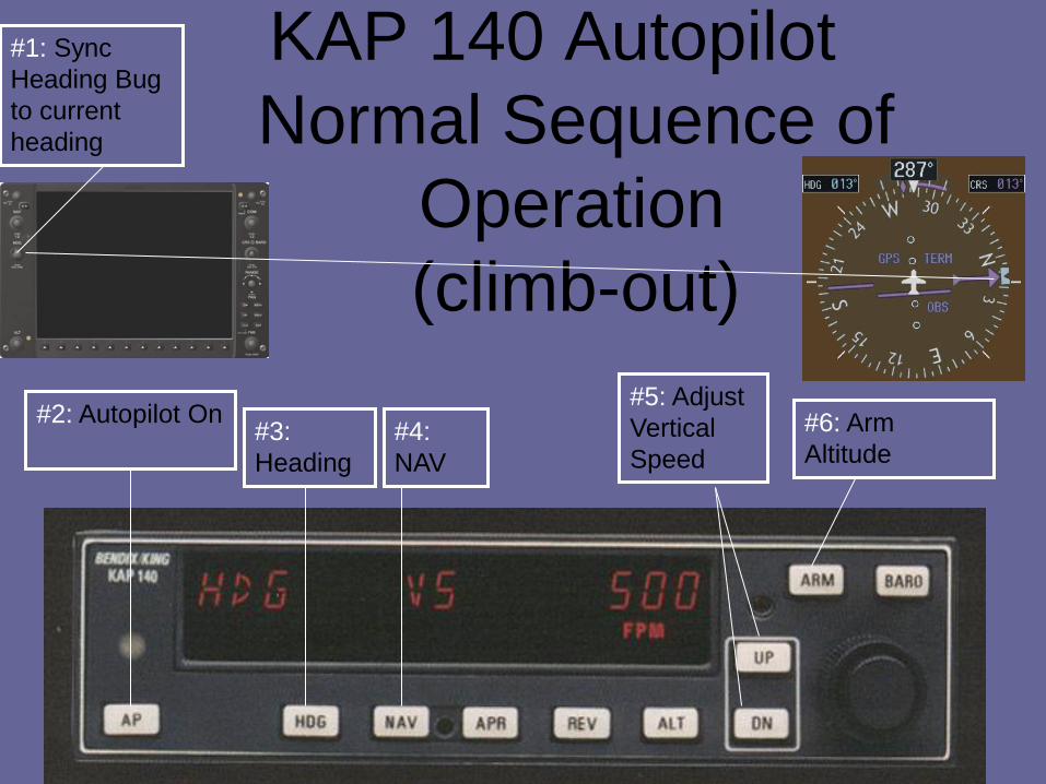
KAP 140 Autopilot
Normal Sequence of
Operation
(climb-out)
#1: Sync
Heading Bug
to current
heading
#2: Autopilot On #3:
Heading
#4:
NAV
#5: Adjust
Vertical
Speed
#6: Arm
Altitude
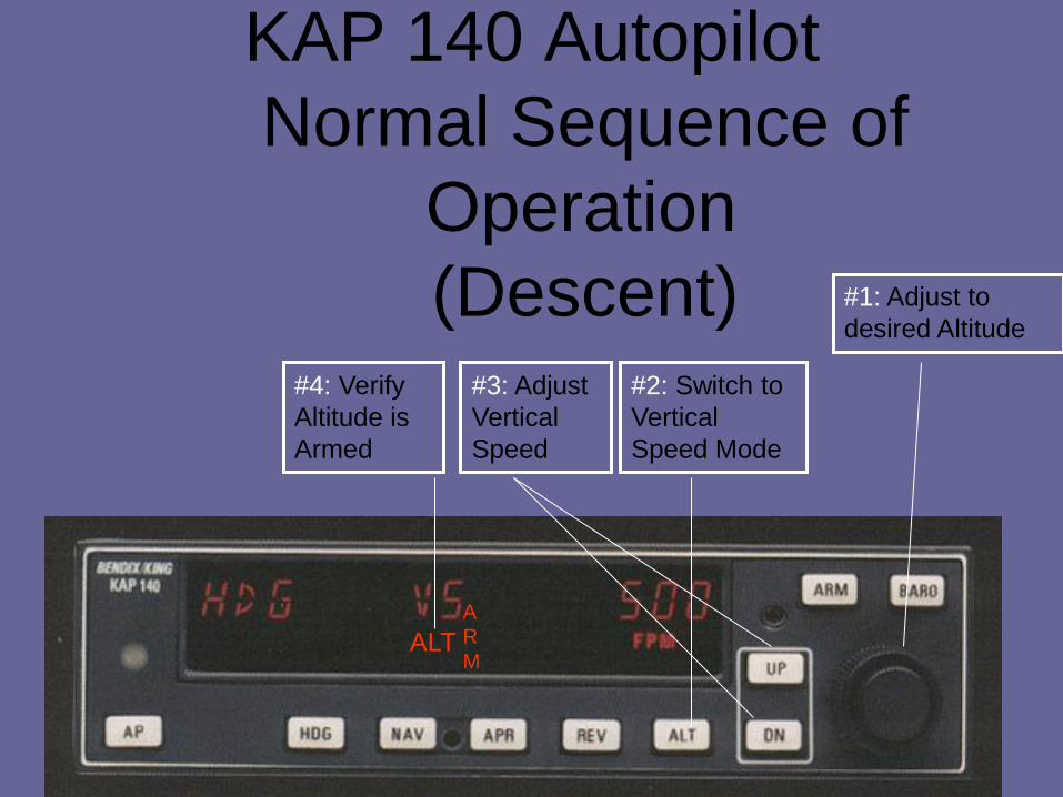
KAP 140 Autopilot
Normal Sequence of
Operation
(Descent) #3: Adjust
Vertical
Speed
#1: Adjust to
desired Altitude
#2: Switch to
Vertical
Speed Mode
ALT
A
R
M
#4: Verify
Altitude is
Armed