garo ls4 / ls4 compact
TRANSCRIPT

GARO LS4 / LS4 CompactInstallation Manual (EN)
GARO ABBox 203, SE–335 25 GnosjöPhone: +46 (0) 370 33 28 [email protected]
anua
l 380
144
2.0
EN

TABLE OF CONTENT
Safety Information 3General Information 3
INSTALLATION 4
NORMAL USE 5
LED light indication 5Technical specifications 10Service information 10Form for annual service and maintenence 11Warranty Conditions 12Warranty Form / Garantiformulär 13
2
EN

SAFETY INFORMATION
The LS4 stations are designed exclusively for charging electric vehicles.
All installation must be carried out by an authorized installer and comply with local country installation regulations. If any questions, please contact your local electrical authority.
Refer to local standards and regulations not to exceed charging current limitations.
To even out the load, it is important to rotate the phases when connecting several of LS4 stations to the same system. Note that 1-phase charging is common in electric vehicles and L1 (left side) and L2 (right side) in the LS4 is used for this purpose.
Ventilation signal from EV is not supported. This means that test of “State D” is not possible.
Adapters for charging connectors are not allowed to be used.
Cord extension sets for charging cable is not allowed to be used.
Do not use private power generators as a power source for charging.
Incorrect installation and testing of the LS4 stations could potentially damage either the vehicles battery and/or the LS4 itself.
Do not operate the LS4 stations in temperatures outside its operating range – see technical specifications.
Each LS4 station is pre-programmed from factory and tested according to the specification from customer. There is no need for any programming or setup by installer during installation.
Each LS4 station is individually marked with a unique “M-number” so that the installer can identify each LS4 station. The M-number label is located at upper right hand side corner behind the front door. When contacting GARO support, please have the M-number available.
LS4 stations that are pre-configurated for backend-solution have the ChargeBoxID (CBID) labeled under the M-number label.
GENERAL INFORMATION
3
EN

INSTALLATION
1. Mount the LS4 and install the supply cable. See picture 1-4.
Phase-rotation is recommended in order to achieve even load on all phases when several LS4 stations are installed to same mains. For example:1st LS4: L1, L2, L32nd LS4: L3, L1, L23rd LS4: L2, L3, L1And so on….
Note: When DLM is pre-configurated from factory, follow the marked phase order label at incoming terminals. All pre-configured LS4 contains the information about this inside the cabinet
The gasket at the bottom of the LS4 need to tighten properly around the mains cable in order to avoid dirt, dust, bugs etc to enter the LS4. See picture 4.
2. In cases with LS4 stations connected in a grid, install TP cable CAT6 with RJ45 connectors between each LS4 station and the provided ethernet router/switch (located ie. in the LS4 master. Se example of ethernet wiring diagram picture 5, 6.
In cases with LS4 stations connected in a grid, installation of the LS4 stations need to follow the installation order in the attached Master/slave file. See table 1.
3. In cases with external energy meter (for DLM function), connect the energy meter communication terminals A- and B+ to LS4 Master station terminals 200 A-) and 201 (B+). The energy-meters modbus adress must be set to #2. The modbus RS-485 communication settings is: Baud 9600, 8bit, 1 stop bit, no parity
4. Turn on the electric power.
5. Test the LS4 station on both sides with a EVSE-tester or an EV. In cases where authorization (by RFID tag or similar) is needed to start charging please contact the backend administrator.
6. Fill in the warranty form completely.
Example of Master/Slave form for LS4 stations connected in a grid
Role Serialnumber / M-numberMaster M00001
Slave 1 M00002
Slave 2 M00003
Slave 3 M00004
Slave 4 M00005
Slave 5
Slave 6
Slave 7
Slave 8
Slave 9
Slave 10
4
EN

NORMAL USE
Connect the charging cable to the EV. If authorization is activated, please hold a valid RFID-tag against the RFID reader on the side of the LS4 you want to use or use the operator app to authorize charging. Charging will start instant if the EV is ready for charging. See your EV charging manual.When finishing charging, follow the EV’s instructions. After charging: Release the charging cable from your EV and place the charging cable at designated place.
Firm
No car connected Charging station available and ready for charging
Car connected State B: Car connected but not yet ready for charging
Car connected State C: Car connected and ready for charging, but charging station requires authentication to start charging (Free Charging = "OFF").
Blinking (3 blinks)
When car connects The charging station detects that the cable is connected, but is yet to detect the car.
Blinking (30 second blink)
Whenever during operation Charging station have received command from backend to start charging and is waiting for car to connect.
Firm
Car connected Charging is ongoing (state C)
Car connected Charging is paused (state B)
Blinking
Whenever during operation Charging station/point is reserved for a specific user
Firm
Whenever during operation DC fault monitor may be defect.
Whenever during charging Residual Circuit Current Breaker (RCCB) triggered.
Whenever during charging DC fault detected.
Whenever during charging Circuit breaker (MCB) triggered - Overload / short circuit
Whenever during charging Type 2 connector motor locking was released/unlocked (the cable can be removed)
When connecting car The socket outlet can not engage locking mechanism to lock the connector.
When connecting car Charging cable is damaged.
light on RIGHT side
Whenever during operation The right side charge controller have lost connection to left side charge controller.
Firm (3 seconds)
When RFID is presented RFID card is not valid or not approved by backend.
Blinking
Whenever during operation Charging station/point is deactivated.
Blinking
When RFID is presented Charging station is verifying the RFID in backend cloud service.
LED light indication When Cause of error
5
EN

NO LIGHT
Charging station and internal meters are powerless.
The upstream circuit breaker have been triggered.
4-pole main circuit breaker inside the bottom of charging station is deactivated.
Charging station is powerless (no LED light), but the internal meters have power.
1-pole main circuit breaker inside the bottom of charging station is deactivated.
The 12V power supply unit is deactivated (Green LED-light [DC OK] on 12V supply unit is not lit).
Upper PCB is not receiving power (DC 12V).
The 12V power supply unit has power, but the charging controller/controllers still do not indicate green on LED-light [Ready]. When operating normally, the LED-light should show blinking green.
NO LIGHT on right side
Directly after powering up station. Left side has LED-light lit, but not right side. No access to left controller web interface.
Right controller is not receiving power (green LED-light [Ready] on controller is not blinking). Left controller is operating normally and [Ready] is blinking.
The cable (USB-->Micro USB) connecting the two controllers is damaged or has bad connection.
LED light indication When Cause of error
LED light indication Measure 1 Measure 2
Firm
No error
Have you tried everything without success? Contact installer or GARO Support (please have M-number available)
Check car settings that can influence charging, i.e gear in parking mode, doors closed, car locked etc.
Present a valid RFID to the RFID card reader (look for RFID symbol), start charging via mobile app or contact charging station operator to start charging remote via backend.
If the charger is supposed to work without RFID/app authentication, contact the backend operator and ska them to verify that "Free charging" is set to ON.
Blinking (3 blinks)
Connect the charging cable to the vehicle, or verify that cable is connected correctly. If no success, try a different charging cable if available.
Blinking (30 second blink)
Connect the charging cable, or verify that cable is connected correctly.
Firm
No error Have you tried everything without success? Contact installer or GARO Support (please have M-number available)
No error
Blinking
No error (contact backend operator if this is not the desired mode)
6
EN

Firm
If the orange "alarm" LED indicator on the charge controller is firm lit, then the charge controller needs to be replaced.
Have you tried everything without success? Contact installer or GARO Support (please have M-number available)
Firm Red light will always generate an alarm to the backend operator.
Reset the RCCB inside the charging station.
Verify that the 8-pole quick connection on the charge controller is properly connected.
Verify correct grounding and phases in building electrical system
When car is connected: Disconnect charging cable from the charging station, then the LED indication shall return to GREEN. Reconect charging cable to start charging. The charging will restart automatically after 15 minutes if cable is not disconnected.
Reset circuit breaker.
Check internal wiring and components for possible reasons for short circuit.
Verify allowed maximum current in backend charger configuration (OperatorCurrentLimit).
Check motor locking wiring and connection for damages. Verify that locking mechanism rod and arm are not stuck.
Verify that the connector is properly inserted into the socket. Light force may be applied.
Verify that there are no foregin objects inside the socket outlet, hence blocking the connector.
Verify that the motor locking is properly installed and without visual damages.
Check charging cable and connectors for damages. Test with another cable if available.
Verify that CP and PP connection pins and wires are not loose or having bad connection.
Verify grounding of charging station.
light on RIGHT side
Check the cable (USB to micro-USB) connecting the two controllers. Replace cable if needed.
Have you tried everything without success? Contact installer or GARO Support (please have M-number available)
If replacing cable does not solve the issue, the charge controller needs to be replaced.
Firm (3 seconds)
Verify that the RFID token is approved by backend (contact backend operator).
Verify that the RFID token is stored in charger internal memory / whitelist (requires certified technician)
Blinking
Contact backend operator and ask for remote activation.
Blinking
No error
LED light indication Measure 1 Measure 2
7
EN

LED light indication Measure 1 Measure 2
NO LIGHT
Reset circuit breaker in upstream switchboard.
Have you tried everything without success? Contact installer or GARO Support (please have M-number available)
Check mainbreaker, reset it if it is deactivated.
Check mainbreaker (1-pole 10A), reset it if it is deactivated.
Verify that 12V power supply unit is receiving 220V AC power via terminals L & N.
Disconnect red/black cables from the power supply unit terminals marked "+/-".
If the power supply unit when red/black cables were disconnected, then it has deteced an earth fault in one of the DC powered components (controllers, upper PCB, router/switch etc.) inside the charging station.
If LED-light [DC OK] remains turned off, consider replacing the 12V power supply unit.
Check red/black cable and connection between DC terminal and upper PCB quick connection (located on far left side of upper PCB in the charging station).
Verify that the controller has 12 V DC power supplied (4-pole quick connection on down-side of controller -> terminal 1 & 2 from the left) and that the LED-light [Ready] is blinking green. If power supply is ok, but no blinking green, then consider replacing charging controller.
NO LIGHT on right side
Verify that the cable (micro-USB on left controller and USB-A on right controller) is properly connected and not damaged. Try replacing with a new cable.
Have you tried everything without success? Contact installer or GARO Support (please have M-number available)
8
EN

LED light indication Indication / fault code in Web UI OCPP fault code
Firm
IDLE (available) - (A) Vehicle not connected
IDLE (available) - (B) Vehicle connected not ready
IDLE (available) - (C) Vehicle connected ready
Blinking (3 blinks)
IDLE (available) - (A) Vehicle not connected
Blinking (30 second blink)
AUTHORIZED (available) - (A) Vehicle not connected
Firm
CHARGING (occupied) - (C) Vehicle connected ready
CHARGING (suspendedEV) - (B) Vehicle connected not ready
BlinkingReserved
Firm
RCD triggered groundFailure
Residual current detected via sensor groundFailure
MCB of type 2 socket triggered overCurrentFailure
Actuator unlocked while charging connectorLockFailure
Plug locking failed connectorLockFailure
Possible CP and PR wiring issue. otherError
Blinking
UNAVAILABLE (unavailable) Unavailable
9
EN

TECHNICAL SPECIFICATIONS
Product type All LS4 models
Standards / Directives IEC 61851-1 and IEC 61439-7
EMC Classification: 2014/30/EU
Installation method: Ground / Wall
Installation environment: Indoor / Outdoor
Location type: Non-restricted Access
Rated Voltage: 1-phase 230VAC 50Hz / 3-phase 400VAC 50Hz depending on model
Installation systems: TT, TN and IT* systems
Charging type: Mode 3
Charging method AC Charging
Protection class: IP44
Mechanical impact resistance: IK10
Temperature range: -25C - +40C
Weight: 22,5 - 24,5kg depending on model
Standard cable length (fixed cable version): Standard 4m
Rated current withstand 10kA
Rated short-time withstand current 10kA
Rated conditional short-circuit current of an assembly 10kA
Short-circuit protective device type Type C
Rated impulse withstand voltage 4kV
Rated insulation voltage 230/400V
Rated current of each circuit 32A
Rated diversity factor RDF=1
Pollution degree: 3
EMC environmental condition A and B
RFID Frequency Band 13.56MHz
RFID output power 250mW
SERVICE INFORMATION
Care and maintenance GARO charging station LS4:The warranty will only remain valid if service is performed.Service is performed once a year and must be documented.General authorization EL is required to perform service, i.e. only a qualified electrical contractor should perform theservice. The service is performed by inspecting the charging station’s exterior and interior parts, manipulatingcomponents and conducting a functional inspection.If the charging station is connected to a web portal or otherwise controlled from an external system via a serviceprovider, the service personnel must contact the service provider before a scheduled service. This is to be able to carry
out all steps in the service, but also to avoid automatic error reports being sent from the charging station when servicestarts that may lead to other service personnel being called out at great expense. Normally the instructions for thecharging station indicate whether it is connected to a superior service.If you have questions about service or a need for service, please contact your GARO retailer.
10
EN
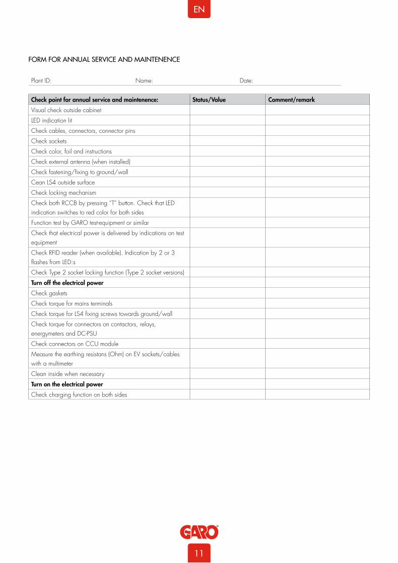
FORM FOR ANNUAL SERVICE AND MAINTENENCE
Check point for annual service and maintenence: Status/Value Comment/remark
Visual check outside cabinet
LED indication lit
Check cables, connectors, connector pins
Check sockets
Check color, foil and instructions
Check external antenna (when installed)
Check fastening/fixing to ground/wall
Cean LS4 outside surface
Check locking mechanism
Check both RCCB by pressing “T” button. Check that LED indication switches to red color for both sides
Function test by GARO test-equipment or similar
Check that electrical power is delivered by indications on test equipment
Check RFID reader (when available). Indication by 2 or 3 flashes from LED:s
Check Type 2 socket locking function (Type 2 socket versions)
Turn off the electrical power
Check gaskets
Check torque for mains terminals
Check torque for LS4 fixing screws towards ground/wall
Check torque for connectors on contactors, relays, energymeters and DC-PSU
Check connectors on CCU module
Measure the earthing resistans (Ohm) on EV sockets/cables with a multimeter
Clean inside when necessary
Turn on the electrical power
Check charging function on both sides
Plant ID: Name: Date:
11
EN

WARRANTY CONDITIONS
1. The product benefits from manufacturer´s warranty. The applicable warranty period must be stated in purchase documents from your supplier.
2. The product must be installed by a certified installer / contractor.
3. Proper installation, storage and operation conditions must be obtained.
4. Warranties apply only to products installed in their original installation location.
5. Installation, use, care, and maintenance must be normal and in accordance with instructions.
6. Warranty requires a dated, fully filled in Warranty form by an certified installer/contractor. If the original installation date cannot be verified, then the warranty period begins ninety (90) days from the date of product manufacture (as indicated by the model and serial number).
7. Warranty does not cover damage occurred by incorrect use of equipment, use of any non-original spare parts, lack of maintenance or faults caused by disassembly of the product or unauthorized persons intervention,
8. Warranty does not cover software or update thereof.
9. Warranty does not cover aesthetic deficiencies caused by negligent manipulation or accidents (breaks or damage to the carcass).
10. Warranty does not cover damage caused by external overvoltage from either grid or car/charging object.
11. Warranty does not cover damage caused by force major like for example but not limited to: floods, winds, fires, lightning, accidents, sabotage, military conflicts, terrorism, volcanos, earthquakes or corrosive environments.
Sverige/Sweden
Garantivillkor enl ALEM 09.
OBS! Fullständigt ifylld garantiblankett krävs.
Garantin gäller ej om produkten varit utsatt för ett isolationstest, sk meggning.
EU Countries (except Sweden)
12
EN

WARRANTY FORM / GARANTIFORMULÄR
LS4 Model: M no:
Electrical installation dataGroup fuse (A):
Supply cable dimension:
Function TestTestbox / EV (model)
Date:
Sign Installer:
Company Name:
Owner / Customer Name:
Installation adress:
13
EN
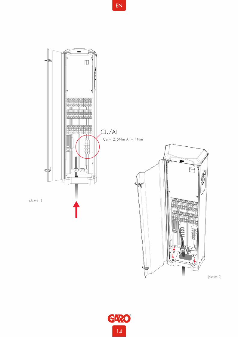
CU/AL
(picture 1)
(picture 2)
Cu = 2,5Nm Al = 4Nm
14
EN

(picture 3)
(picture 4)
15
EN

3pcs LS4 connected with TP CAT6 cable to router/switch
5pcs LS4 connected with TP CAT6 cable to router/switch
(picture 5)
(picture 6)
Example of DLM meter installation
Modbus address #29600, 8, 1, no parity
Terminals:#200 - A-#201 - B+
DLM meter
16
EN

Standard
-KF1
-X12V
-X0V
12V
230V
-KA1 -T1
-QA1-XN1 -XPE1
-RFID2
-XD2
-QA2
-SW1-RT1 -CC1 -CC2
-RFID1
-XD1
16/32A
16/32A
-FC1 -FB1 -P1
-FC2 -FB2
-Q1 -FC3
-X1
-L1-L2-L3-N-PE
-P2
-EB1
Q1 = Main breaker 100A
FC3 = Fuse Charge Controller and Powersupply
P1 = Energymeter Left Outlet
P2 = Energymeter Right Outlet
FB1 = RCCB Left Outlet
FB2 = RCCB Right Outlet
FC1 = Fuse Left Outlet
FC2 = Fuse Right Outlet
QA1 = Contactor Left Outlet
QA2 = Contactor Right Outlet
XN1 = N Neutral terminal
XPE1 = PE Terminal Protection Earth
T1 = Powersupply DC
CC1 = Charge Controller (Master)
CC2 = Charge Controller (Slave)
RFID1 = Left Receiver
RFID2 = Right Recevier
KF1 = Led light Topcard
X1 = Incoming terminal
XD1 = Left charging connector
XD2 = Right charging connector
RT1 = 4G - Router
SW1 = Ethernet Switch
KA1 = Contactor for Heater Cold Options*
*Cold Option is optional
*RT1 (router) and SW1 (switch) is not possible in same LS4
17
EN

18
EN