gary chinn, john a. sainsbury the carpenter's companion 1980
TRANSCRIPT

The
••
anton
Garry Chinn and John Sainsbury
The Carpente~ Companion A bad workman always blames his tools. Tbac saying ~y be trw:, but anyone will work &iter u5fnBtbHisht tGDl fur-tt.-right Job~ ad this book will help every crafUman to achieve just rhis.
Carpentry is a skjll which has been .,.sse<! down through thecenruria. Today, in an age of mass ~~irisbeth~ing&ad rebxing ro produce band-made futniture aod liniflss. TbiC~'C~ IS an essditial book
for both~ inaperienc:ed and experienced wu:llt ...... 'f.tuQup~~ and lane drawmss. ir shows the home woodworker how ro choose and use the 6nest rools~y and effectiv~ so that the~ result is both practical and aesthetically pleasing.
The subjects covered an the chapters are both fundamental and specialized: the history of tools; rheir maintenance; how to plan a workshop; :wbi,h.plane ro buy; points to watch tOe w!M.n bctyio5uaw; uaiq veneeriag, carving, turning and boring tools. There are step-by-srtp projects showing how tb make a otawing jig, a wOrkbench and a carving vice, and charts showing the diffcttnr varieties of equipnaeat. including jig saw blade5-, naili, screws and abrasive papers, in addition to a comprehensive glossary.
ThtWirpmw.-s Cam/)IIIIPIII is lavishly tllustrated with colour and black and white photographs and dear, informauve line drawmgs, covering everything the woodworker needs to know.
:£6.9S
The Carpenter~ Companion

The
~ar enter's •
~om an1on Garry Chinn and John Sainsbury
Marshall Cavendish London & Sydney
A QUARTO BOOK
Copyright© 1980 Quarto Publishing limited
This book was designed and produced by Quarto Publishing Limited
32 Kingly Coun, London WI Designer: Roger Daniels Editor: Jane Struthers
Captions: Richard Crossman, Jim Roberb Line Illustrations: Helen Down ton
Published by Marshall Cavendish Books Limited 58 Old Compton Street
London WIV SPA
First printing 1980
Phototypeset in England by Parker T ypesertiog Service Printed in Hong Kong by
Leefung-Asco Printers Limited
ISBN 0 85685 730 0
All righu reserved
6

CHAPTER ON£
Tools, whether of stone, bronze, iron or steel, are a
result of man's versatility, his increasing skills through the centuries, and his mastery of
many skills.
7
A HISTOR}' Of TOOlS
\\'HETtlER 01' STO'IE,
bron7e, iron or steel, tell the ~tory of man. His need for domestic "-'orking and '' ar tools describes his ver~atilin , h1' increasing skill~ throu~h the tcnturie,, .md hi., ma<,tcr: of manr craft,. Hi' U'l~' of wood i., shown throu~h till' hundred'> of diffcrcm ryp<:'> which h.nc been ~craped, can·ed, sawn, planed, molded and fashioned to meet hi~ manv .md varied needs. ·
looking at many of the toob of LOd.n., vou could easily sav that the\ ha' e not ch:tnged very much in sever~) thom.tnd vears. "-.e,enheJe,s, the\ h,l\ e changed, particular!} as rna~ became better at processing ra\\ material~ and he began tO study the need' of mankind itself. A~ far a'> woodworking tool~ art• con
cerned, tht>re wen: three marked arc,1, of development. The Ronuns m.1dc we.H progrc.,., using iron md steel in sa\\ bl.1des and produced jack, smoothing, plou~h and molding planes, but it "as not until after the Dark and Middle A~c., th.n further ad\ances were made. TIH.' mo'>t '>ignificant time '':1' trom 1600 1800, when the tenon ~aw, '>pokc'havc and marking out rools .1ppe.ued. The screwdriver, all-metal plane, brace, brea~t drill and auger bits appeared later.
r.Lm\' tool' of the past were made bv a aah \man to ~;uit his own ne~:d~ .tnd. a\ fauories \\ere builr w meet the ~rowm~ tkmand for crafting tools, the} copied the local man-made product~. A:. a resulr, many of them were quite ornarc, \Ct still functional. Thcv often bore ~ame\ linking them to their place of origin, ant! later craftsmen grew :~~.:cu~tomed to tho~c particular wol' .md would .tcc.:ept no other.
In the early parr of the Industrial Re,·olution in Europe, craftsmen and apprentices alike found little time for the leisurely making and cmbdli~hmcnt oi tool,. A<:. .1 r~ulr, rhc hand-nlJdc, inJi, iduall) desi~ned tOol intlucm:e JcdincJ and made" ay for more ~impl} Je,igncd, purely functional tools.
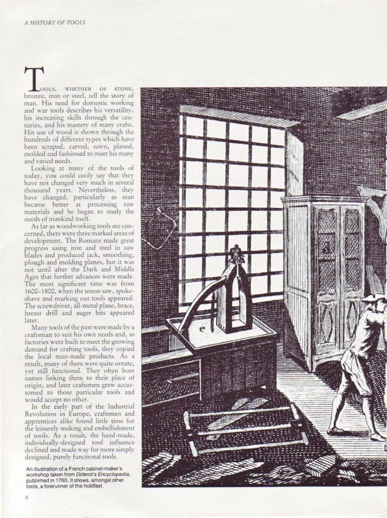
An tllustration of a French cabinet-maker's workshop taken from D1derot's Encyclopedia , pubh$hed In 1760. It shows, amongst other tools, a forerunner of the holdfast.
!i

A HISTORY 01 TOOU
9

A fi!STOR>' Or TOOLS
Saws The saw, like the plane, dates back to the :--.:eolithic or later Stone Age wh1ch "·as well before the di~co,·ery of mctal~. The stone ~aws ~ere <;hapcd and <.:ut ven mu~.:h as the material itself dinated but' the later bronze tool could be shaped and formed. The earliest saws had the teeth inclined tow,trds the handle '10 that they cut on the pull ~truke.
aws from I 00 sc have been iound ott GLlswnburv and one d1scovered .u Cambridge had a blade "-'ith 7 points per inch 2Smm, all pointing towards the handle. The Romans h.td frame ~J\\ s, narrow-bl.tdcd hand saws and large ams cut ~aws with handles at both end"
10
and they recogni7cd the need for accurate setting of the teeth to right and left.
ln the United St.He<; Henry Disston did much to influence de,•dopment, and he began manufacturing in 1844. He made the first crucible cast steel ro be used in saws and de,·eloped a style and class all his own. Before long, he had captured the American market and ''as also e:-.porting hi~ ~.1ws to Furope. Ha,·ing dc,doped the skew back saw, he went on tO set a standard for others to foliO"-' with his rip sa'', which had 51 :!
points per inch 25mm and was 26 inches/ 650mm long, and his cross cm, which had 7 points per inch/25mm and from 20- 26 inches/SOC 650mm long.
Some beauttful examples of early saws Top, an eighteenth-century veneer saw. Left, a French armchair·makers saw and cramp. Above, a small bow saw
The modern hand saw come!> from Holland where, early in the cight(.'Cnth century, they designed a pistol-grip handle for greater control and comfort. \X'hen the process of rolling wide steel strip wa'l perfected in Sheffield, S.l"- ~ '' ith "-ide blade\ were designed. ·n,e~e were quickly followed in the Gnitcd Kint.:dom b, a h.mJle ma<.k from a 1l at ~trip of "-'Ood wah a slor for tht• hn~cr' and attached to the blade "-'ith ri\"l't,. s,-1750, this pattern "·as firmly CJ>tablished and in its basic form has survived tO rhc prc)ocnt day.
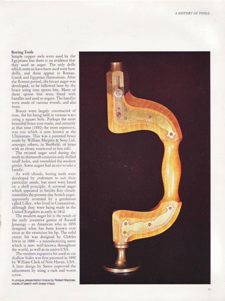
Boring Tools Simple copper awls were used by the Egyptians but there is no evidence that they used an auger. The only drills which seem to have been used were bow drills, and these appear in Roman, Greek and Egyptian illustrations. After the Roman period, the breast auger was developed, to be followed later by the brace using iron spoon bits. Many of these spoon bits were fined with handles and used as augers. The handles were made of various wood~, and also bone.
Braces were largely constructed of iron, the bit being held in various ways using a square hoJe. Perhaps the most beautiful brace ever made, and certainly .u that time (1850) the most expensive, was one which is now known as the Ulumatum. This was a patented brace made by William Marples & Sons Ltd, amongst mhers, in Sheffield, of brass with an ebony rosewood or box infil.
The twisted auger used during the tenth to thirteenth centuries on1y drilled small holes, and resembled the modern gimlet. Some augers had an eye to take a handle.
As with 'Chisels, boring tools were developed by craftsmen to suit their particular needs, but most were based on a shell principle. A screwed auger which appeared in Smiths Key do~ely resembles the present-day Scotch auger, apparently invented by a gentleman caJ1ed Lilley, who lived in Connecticut, although they were being made in the United.Kingdom as early as 1812.
The modern auger bit is the result of the early inventive genius of Russell Jennings - an American who in 1855 designed what has been known ever since as the extension bit lip. The solid center bit was designed by Ch<'!rles Irwin in 1884- a manufacruring name which is now well-knO\\ n throughout the world, as well as its native USA.
The modern expansive bit used to cut ~hallow holes was first patented in 1890 by William Clark of New Haven, USA. A later design by Steers improved the adjustment by using a rack and worm screw. A unique presentation brace by Robert Marples. made of beech with brass inlays.
A Ff!STORY OF TOOLS
II

A HISTORY 01 TOOLS
Planes In the latter half of the nineteenth century, great progress in the design of facton -made tools was made, credit for "hich. must go to the United )tate!>. ~lam people believe that toda} 'c; metal pbne i-. ,1modcrn design. HO\\ ever, thi' IS "rong ,1!> it wa~ Leonard Baile} .1nd his contemporaries who bridged the gap from wood tO metal "·ith designs which ha\C surYived a centurv in common use and may well see another c<.:ntury out. The wooden plane of 2000 year'> ago ic, '>till U'>ed in many European and other countries todav, .. umcwhac modified perhaps, while i:he metal plane ha~ only been generally accepted in Korth America, the United Kingdom and the F ngli .. h-~peaking countries of the Briti'h Commonwealth.
The first iron plane was dc~igned b) :tn American in 1827, who patented a plane "'ith a cast iron stock but no cutter adju~cmcnt . TD \X'orrall of the Lo" ell Plane and Tool Company followed this de,·elopmem by designing plane~ with metal superstructure~ and wooden sole , and a device l'.·hich ughtencJ the iron in place.
The first really marketable plane, howe,·er, came from Bailey in 1858. He introduced a lever cap for the quick withdrawal of the cutting unit and a cutting iron adjustment through a Yshaped lever (which first worked in the vertical but was later changed to the horizontal), both of which are still u'led toda} . Bailey abo devised the bent cap iron for perfect functioning of the cutter and introduced the rhin cuttin~ iron. Lucr, he joined with Stanley Rule and I cvcl Company and became .superintendent of their plane manufacturing divi ... ion.
Another Stanley man, Justus Traut, designed the lateral adjusting lever which has also survi,·ed to the present dar. Various frog adju~tments were made b} other clever and kno".ledReable men so the metal plane, ,·cry lih the one thev knew has sun·ivcd a century. St;nley sr{Jl recognize the work of these men by placing the name Bailey on the front of their bench plane bodies.
The metal combination plane was
12
1
2
5
3
6
Above lett, five planes which were tllustrated tn D1derot's Encyclopedia of 1760. 1 a smoothtng plane; 2 a jointer plane: 3-4 rebate planes; 5 a jack plane. Above right, part of a late eighteenth-century wall painting in the Hotel de Vtlle, Paris, showing a trying plane in use. A fifteenth-century illustration. left, of a carpenter ustng an ax. Right, a moldtng plane made about 1725 by the earttest authenticated professiOnal English planemaker, Robert Woodtng Th1s end sect• on shows how the plane cut the WOOd

dt!veloped at the same time as the bench plane. The first one wa~ patented by Thomas Worrall in 1854 and an iron fillister was made by William S Laughborough in 1859. Charles Miller of Brattleborough most influenced the de,·elopment of this plane, and his vcork "ith Bailey, m~ether with the im·enrions of Ju!>tus Traut, eventually brought abour the appearance of the world-renowned Stanley forty fi,·e. This was further de,·eloped into the Fifty Five. The Forry Five is still made by Record Ridgway as the 405. These planes had many cutter~ and could
A HISTOR>' OF TOOL<;
reproduce almost all the known mold ings and other shape~. The planes whtch came from Stanley were designed to cover almost every known woodworking application.
A few still surYi,·e, bur anyone who has held and used a Stanley 'o 4H dovetail dado cutting plane, for example, will have realized and appre cia red irs remarkable quality.
The steel plane was perfected in rhe United Kingdom by two companies in an almost identical way - by Stewart Spiers of Avr and Thomas Norris of London. This plane was developed
IJ

3
A HISTORY OF TOOLS
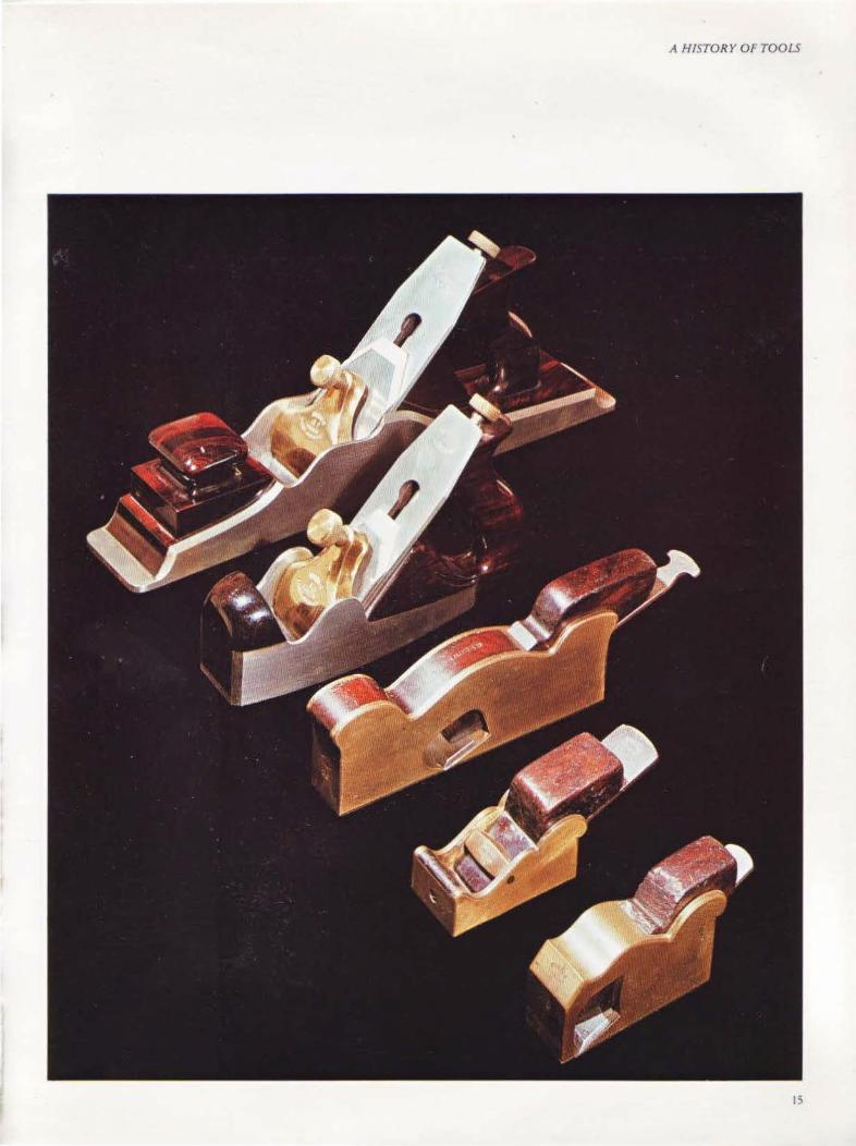
1 Craftsman-made left- and nght-hand side 2 rebate plane. 2 These highly-decorated shoulder, bullnose and left- and right-hand side rebate planes were made by Preston in the late nineteenth century. 3 Violin-maker"s planes. The top one was made by Noms, and the rest by Preston. 4 A screw-stemmed, close-handled solid boxwood plough plane. Facing page, a collection of Norris planes-a dovetailed steel panel plane and a smoothing plane, both made about 1920, a steel-soled brass chariot plane and a bullnose plane.
A HISTORY OF TOOLS
IS
A HI~TORY Of TOOLS
from the early nineteenth-century mitre plane and consisted of a steel box-like body, with sides so finely dovetailed to the sole that often the joints could not be seen. The cutting unit Wa!> held in place either ·with a 'lcrcw-adjusted lever cap or a '' cd~e, and the body was infilled with timber - usuall} rosewood. The} also made planes using the more com·entional grey cast iron or gun metal. The handles were rather differently shaped, and the front handle was usually square with rounded corner<; and sides.
Smoothing planes either copied the older wooden coffin shape or had parallel sides. They were superb craftsman tools without equal anywhere.
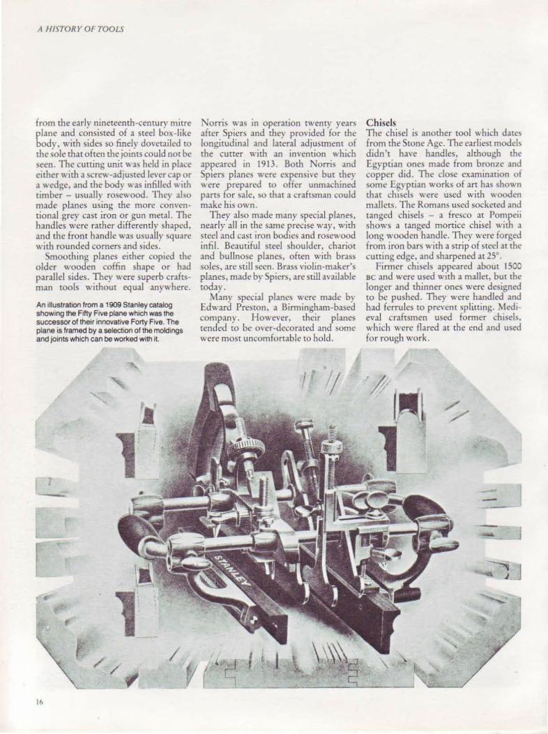
An Illustration from a 1909 Stanley catalog show1ng the Fifty Five plane which was the successor of their innovative Forty F1ve. The plane is framed by a se1ect1on of the moldings and jo1nts which can be worl<ed with it.
16
Norris was in operation twenty years after Spiers and they provided for the longitudinal and lateral adjustment of the cutter with an im·ention which appeared in 1913. Both Norris and Spiers planes wen~ expensive but they ''ere prepared to offer unmachined pans for sale, ~o that a craftsman could make his own.
They also made many special planes, nearly all in the same precise way, with steel and cast iron bodies and rosewood infil. .Beautiful steel shoulder, chariot and bullnose planes, often with brass soles, are still seen. Brass violin-maker'.; planes, made by Spiers, are still available today.
Many special planes were made by Edward Preston, a Birmingham-based company. However, their planes tended to be over-decorated and some were most uncomfortable to hold.
Chisels 111e chisel is another tool which dates from the Stone Age. The earliest models didn't have handles, although the Egyptian ones made from bronze and copper did. The close examination of ~ome l:.gyptian works of art has shown chat chisels were used wich \\.OOdt!n mailers. The Romans used socketed and ranged chisels - a fresco at Pompeii shows a ranged mortice chisel with a long wooden handle. They were forged from iron bars with a strip of Heel at the cuning edge, and sharpened at 25 .
Firmer chisels appeared about 1500 sc and were used with a mallet, but the longer and thinner ones were designed to be pushed. They were handled and had ferrules to prevent splitting. Medteval craftsmen used former chisels, which were flared at the cnJ and used for rough work.

Tool C hests All these tools, so highJy prized, were carefully looked after and often kept in beautifully-made tool chests. These were u~uilly painted on the outside, but the interior~ were fitted with drawers made of mahogany or another high-
qualiry hardwood. The lid was almost invariably veneered and inlaid, and sometimes the design incorporated the initials of the owner or a motif of tools. Thev are extremel't valuable and were ofte~ handed down from father co son. complete with his quality tools.
A HISTORY OF TOOLS
This beautiful apprentice tool chest was made in 1858, usmg a wide variety of woods. The lid is inlaid with ebony, rosewood and 1vory, wrth comer designs in ebony, on a background of birdseye maple surrounded by borders of rosewood, satinwood, quartered rosewood and crotch Spanish mahogany.
17

IS
CHAPTERnto
The orkshop
To obtain the greatest enjoyment w ithout frustration ,
a w orkshop is required w ith its one essential- the w orkbench .
..
19
THE WORKSHOP
W o .. oo•"G IS A SKILl bu;lr up over man) years, the beginner usually starting with a small number of tools. His earliest skills will have been learnt at school in a friendly, relaxed at~osphere, with rhe relatively ~ophi\tt(ated backqround ot the school and college workshop.
Ha,·ing acquired a taste for crafting in wood, he may well wish to work in a specialized area, as opposed co one which is more general. This may be brought about by rc\tricriom of space, number of tool!., or eYen rhcir co~t. Howe,·cr, ro obratn rhe grearesr cnjo)ment withour frustrarion, he will need a workspace of some kind, with irs onc essential - a workbench. As his experience grows, so will his need for more tools to ad,ance his work and to save ume.
Probably one of the firsr dect~iom which has to be made is v:herher or nm the workshop is tO be used purely for leisure, or to produce articles for sale. Obviously, thought must also be givcn to the number of people who may be found working in rhc shop at an) one rime. Generally. we can think and plan \\ irh the horne workshop in mind -expansion of the suggested space and its equipment can naturally follow, should the need arise.
The location of the workshop will depend on a numbcr of factors. Jdeall). it should be close ro rhc house, partie ularh- in countrie) with severe ''inter conditions, so that an extension of the hearing. system can be arranged. In
r onh America, most homes have basement~, and the~e are ideal, but care mu~t be taken to prevent or eliminate damp.
Where a separate building is planned, verv careful selection of vour material~ is 'vital. Galvani7ed i~on sheeting, asbestos or concrete should nor be used ~ince these condense badly, ·bringing about r,1pid deterioration in tools and materials. A timber or brick building is best. The insulation of both wall~ and ceiling is important. The floor, prefcrabh- wooden, should be treated with preservative but left unpolished - a slippery floor can be dangerous . horn time to time, a wooden surface can become highly poli~hed by shavin~~
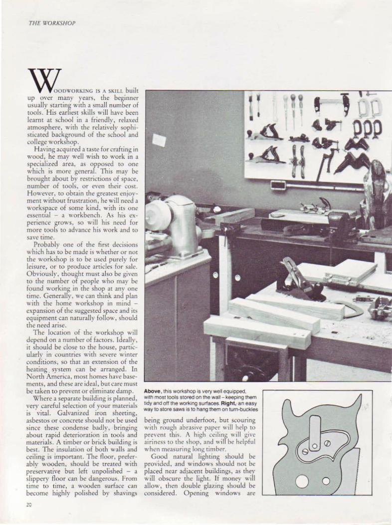
Above, thiS workshop IS very well equ1pped. w1th most tools stored on the wall-keep1ng them lldy and off the work1ng surfaces. Right, an easy way to store saws IS to hang them on turn-buckles
being ground underfoot, but scouring \\ irh rough abrasi' e paper will help to prevent rhi \. A high ceiling will givt• .1irincs~ to the 'hop . . md will be helpful when mt>a~urin~ long timber.
Good natural lighting should be provided, and 't\ indows should nor be placed ncar adjacent buildings, as they \\ill obscure the light. If money will allow, then double glazing should be considered. Opening windows are
0

essential and, in mam areas, the addi tion of fly screens· is necessary. A \\ indow which can be fully opened will be useful w pass long timbers through when planing or sa, .. ing. Generous anificiallighcing, using fluorescent tubes of rhe nonstroboscopic type, should be in<,tallcd. If a woodrurning lathe, morticcr and machine drill, band saw or jig saw are installed, they !.hould each be indi,·idually lit. Inadequate lighting can be dangerous. As "·ell as individual lighting, a flexible light near the bench for modeling work is vital.
Priority should be given w the
positioning of either three- or singlephase electrical oudets. Fusing should be adequate and saiery switches provided with each machine. Trailing "ires or cables should be avoided where,·er possible, and power outlets c;uspended from the roof for the connection of portable power tools will help to prevent this. A ma\tcr switch placed conveniently near the door will permit the isolation of all circuirs on lea\ing the shop, and help to eliminate any possibility of short circuiting.
In the small workshop, it will be more convenient if tlw table sa'''' .1nd
THE \TORA.SIIOP
planer can be equipped with , .. heel~ to permit easy storage and conserve space.
Should you choose to set up a workshop in your home, the basement, garage, attic or other spare room will ha.,.·e orne of the aforementioned facili ties. Tt wiJI not be difficult to prov1de more of these, though the elimination of moisture from the garage may prove a problem. The garage is often pressed mto use for many craft activities, but it can be restricti\'e \\'hen the layout of tools and equipment is being considered. Nevertheless. it has its advantages when machining large timbers, and often has ideal roof space for timber storage.
The design and construction of a folding workbench, complete with storage space, is vital, if it is considered unsuitable to sere" on a simple vice to the kitchen table or work top.
,Planning the Workshop Layout lf at all possible at the outset, draw up a list of the machines and other floorstanding equipment which you will need, even if) ou buy your tool~ one or two at a time O\'Cr a fe,-. years. Dra\\ to scale a floor plan, indicate window and door positions, and make from thin card templates to represent each piece of standing equipment. Take each one in tum and place it in the most convenient position, having in mind its u~e. its lighting needs and the free passage of material through and out of the machine. Shelving and other storage units can folio\\.·, and be fitted into convenient spaces. Many woodworkers prefer to have those tools which are most commonly in use, ready to hand and located on pegboard, using purpose-made hooks and pegs. Special planes, housed in their original boxes, will be stored best in cupboards to protect them from dust. Ample space should be left around the machines.
Timber should be stored separately and, when in seasoning, kept in openended buildings to ensure a free passage of air. Timber, plywoods, hardboards and multiboards which are ready for use are kept best in a dry situation close to the workshop, but not necessarily inside it.
21
THE WORKSHOP
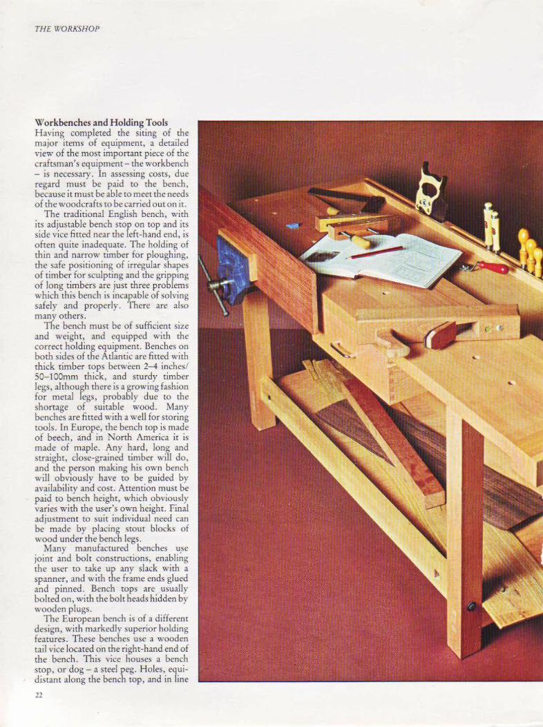
Workbenches and H oJdjngTools Having completed the siting of the major items of equipment, a detailed view of the most important piece of the craftsman's eq uipmem- the workbench - is necessary. In assessing costs, due regard must be paid to the bench, because it must be able to meet the needs of the woodcrafts to be carried out on ir.
The traditional English bench, with its adjustable bench stop on top and its side vice fitted near the left-hand end, is often quite inadequate. The holding of thin and narrow timber for ploughing, the safe positioning of irregular shapes of timber for sculpting and the gripping of long timbers are just three problems which this bench is incapable of solving safely and properly. There are also many others.
The bench must be of sufficient size and weight, and equipped with the correct holding equipment. Benches on both sides of the Atlantic are fitted with thick timber rops between 2- 4 inches/ 50-lOOmm thick, and sturdy timber legs, although there is a growing fashion for metal legs, probably due to the shortage of suitable wood. Many benches are fitted with a well for storing rools. In Europe, the bench top is made of beech, and in North America it is made of maple. Any hard, long and straight, dose-grained timber will do, and the person making his own bench will obviously have to be guided by availability and cost. Attention must be paid to bench height, which obviously varies with the user's own height. Final adjustment to suit individual need can be made by placing stout blocks of wood under the bench legs.
Many manufactured benches u.se joim and bolt constructions, enabling the user ro take up any slack with a spanner, and with the frame ends glued and pinned. Bench tops are. usually bolted on, with the bolt heads hidden by wooden plugs.
The European bench is of a different design, with markedly superior holding features. These benches use a wooden tail vice located on the right-hand end of the bench . This vice houses a bench stop, or dog- a steel peg. Holes, equidistant along the bench top, and in line
22

THE WORKSHOP
This beautiful, class1c, English workbench shown far left is made of beechwood, and held together with coach bolts. This model has a slot along the back edge 1n which to store tools and a shelf beneath the top to hold pieces of timber and large tools. Both VICeS have quick-release levers, and the one on the nght-hand s1de is fitted with a tarl vrce wrth a sliding dog However. benches are also avarlable with other vrces, such as the ones shown left. A rather more unconvent1onaltooi1S the combinatron vtce. above, which rests on, or extends from, any flat surface up to 2Y2 inches/62mm thick. It will hold flat, round and tnangular workpieces.
23

T/1[ \\DRA'SIIOP
Making a Portable Workbench
This tS a stmple folding workbench whtch can be stored in your katchen or spare bedroom. It is equipped with a vice, bench stop, tool rest and a bench hotdfast The whole bench can be constructed using standard timber and fittings easily bought from a DIY shop.
Cutting List All dimensions are finished sizes. No allowance has been made for waste or cutting. Sizes are given as imperial/metric.
Sundries 2 yards 2 feet/2.4 meters of 31-inch/ 9-mm diameter dowel 2 pairs 21/2 inch/63mm flush butt hinges 2 pairs 2 inch/50mm back flap hinges 2 112 inch/63mm hook and eye 2 dozen ¥-linch/ 19mm x No 5 countersunk screws 2 dozen o/a inch/16mm x No 10 countersunk screws 2 dozen 1 Y• inch/32mm x No 8 countersunk screws
Suggested Bench Fittings No 50 Record Vice No 169 Record Bench Stop No 145 Record Bench Holdfast or equivalents
24
MainFrame 2 Legs (a) and (b) Top rail (c) Tool shelf (d) 2 Bottom rails (e) and (f) Tray bottom (g) Tool panel (h) Vice mounting block (i) Strip (j) 2 Tray supports (w)
Legs 4 Le~s (m) and (n) 4 Rails (o) and (p)
Tops Fixed top (q) Hin~ed top (r) Bao edge strip (s} 4 Edging strip (t) 4 Locating pegs (u) 4 Stops (v) 4 Vice cheeks
Length 30%/760 30:Vs/760 30;11/760 303,11/760 30%/760 30%/760
8/200 30-%/760
4Ve/102
30%n60 10%1265
36~/914 36%/914 33Va/927 21 '14/533 1~/32
1/25 71/•/180
Making the Main Frame Cut and prepare pieces (a}, (b), (c), (d), (e) and (f). If you are using planed timber the only preparation necessary is to cut atl the above pieces 30JA! inches/ 760mm long. Make sure that all the ends are sawn squarely if they are not to be finally planed.
Set the bush earners and fences to the sizes shown an diagram 1.
Fig1
Assemble the jig on the end of piece (c) and drill both holes 1 inch/ 25mm deep. Repeat this process on the other end of the piece and for ptece (d).
Fix the adjustable head at its limit on the rods and assemble the jig on the inside and against the end of piece (a). Dr111 both holes~ inch/ 16mm deep (diagram 2). Repeat on the inside of piece (b).
1: a ,b
369 Fig 2
Mark lines squarely across the inside of pieces (a) and (b) as shown in diagram 2 .
Remove the fences and locate the jig along the line on piece (a}. Drill both holes. Repeat on piece (b).
Reset the bush earner datum lines at 1 inch/25mm and 2;. inches/ 70mm and replace the fences at 'I,. tnch/ 11mm.
Width Breadth Material 5%/146 'Ve/22 Softwood 4%/120 'Va/22 Softwood 4;4/120 1/e/22 Softwood 3¥4/95 Ve/22 Softwood
4' 0/,.1124 •t •• /4 Plywood 15Y•/380 :Y../19 Block board 4%/120 :l/4/19 Block board :V•/19 :Y•/19 Softwood
•t .. /13 9! •• / 13 Softwood
2~/57 1/e/22 Softwood 2¥•157 71,122 Softwood
7~'4/194 3/4/19 Block board 13%/340 :Y../19 Blackboard
1¥4/44 Va/22 Softwood %/19 v.J6 Hardwood ~/9 Dowel
";,./13 "J,./13 Softwood 2¥.170 %/9 Softwood or
Assemble the /·;g on the end of piece (e) anddril both holes. Repeat this on the other end and also on both ends of piece (f).
J: a . b I I l-J
Fig3 133
Draw hnes on pieces (a) and (b) as shown in diagram 3. This is the center of 1he top holes to locate the rails of the tool tray.
Remove both the reference head and the adjustable head and attach the doweling Jig to piece (a) with a jig clamp, fences against the edge.
Reassemble the jig against the other edge and repeat lor the holes to receive the back rail of the tool tray. Repeat both stages on the inside of piece (b).
As drilling for dowels has now been completed, cut 16 pieces of %-inch/ 9--mm wide dowel 1 h inches/38mm long, and assemble the whole framework dry, to check 11 Do not glue up at this stage.
Cut rebates 7/,. inch/ 11 mm w1de x '"• inch/4mm deep in the bottom edge of pieces (e) and (f) to locate plywood base of the tool tray. Alternatively, a •t,. inch/13mm square or quadrant strip may be attached to form a rebate.
Making the Legs As both frames are Identical, instructiOns will not be repeated for the second frame.
Cut all four legs (m) and (n) 303ta i nches/ 760mm long and all four rails ( o) and (p} 1 0% inches/265mm long.
Set bush carrier datum.lines (diagram 4} and fence to '!,. inch/ 11mm.
Fig4
Assemble the jig on the end of piece (o) and drill both holes 1 inch/ 25mm deep. Repeat on the other end. Repeat for (p), and then repeat th is procedure on the second frame.
Remove the adjustable head and assemble the jig against the end and on the lace edge (x} of the leg (m} and drill both holes.
Repeat on leg (n} and also on both Identical members of second frame
Mark a line across the face edge of all four legs (diagram 5). This is the center line of the top hole of the bottom rail.
I· • m,n
Plywood I Fig5
Remove both the reference head and the adJUStable head and attach the 119 to the edge of the leg. Drill both holes. Repeat on other legs.
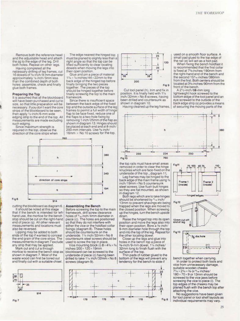
Hav•ng completed all the necessary dnlhng of leg frames cut 16 dowels of 1 a-lnCh!9-mmd•ameter aoprox•mately '• lnch.'3mm ess than the combtned depth of both holes: assemble, check and finally glue both frames.
The edge nearest the hinged top must be planed to slightly less than a right angle so that the top can be titled suff•c•enUy to clear locating dowels when mov•ng the legs mto the1r open pos•t•on
Glue and p•n a p1ece of matenal 1 1• • 1, 1nches 144 · 22mm to the back edge of the h•nged top before f1nally bnng1ng the two pieces together The p1eces of the top should be h1nged together before
Preparing the Top finally screw1ng the top to the ma1n It IS assumed that all the blackboard framework. Will have been purchased and cut to Since there IS Insufficient space SIZe, so that httle preparation w1ll be between the back edge of the f1xed necessary. If you don't want the core top and the outs1de surface of the leg stnps of the block board to be seen. frames to perm1t a full w1dth of h1nge then apply '•·inch/6-mm wK!e flap to be face hxed. reduce one of edg1ng stnp to the end of the top All the flaps to a two-hole fixing by measurements are made exclud•ng remov1ng 11nch 25mm of the flap as such edg•ng. I shown 1n d1agram 13. Hinges should
Smce max1mum strength is be placed at each eno and at8-1nch • requ~red 1n the top, observe the 200-mm 1ntervals. Use sa inch/ d,recuon of the core stnps when 16mm No 10 screws for the top.
r------ .lAO
j h "] -
380
r 340
~
dlfectoon of core stnpS ·~ q 194
F1g6 ·--....,...,....,----- --1 914
cutting the block board as diagram 6 It should be noted at th1s stage
that 1f the bench is Intended for lefthand use. the mort1ce for the bench stop should be cut on the nght-hand end of p1ece (Q). All other relevant measurements and locations must a so be reversed.
L1pp1ng may be added to both ends of the top 1f wanted to conceal the end gra1n of the core stnps. The measurements in d1agram 7 exclude any stnp that may be applied.
Mark out and cut a through mort1ce to receive the bench stop as shown in d1agram 7. Most of the waste wood can first be bored out and finally cut w1th a surtable ch1sel.
I;~~ .I 914
Fiv 1
Assembling the Bench Before screw1ng the top to the maiO framework. dnll screw clearance holes of' ,.,nchl4mm diameter 10 p1ece (c) The holes are positioned so that they do not Interfere with either the VICe or the holdfast collar fixings (diagram 8) These holes should be countersunk on the underside. 1 \• lnch/32mmx No 8 countersunk steel screws should be used to screw the top in place.
V1ce mountmg block (i) ax 43,• x l• inches/200x 120x 19mm blackboard can be screwed to the underside of p1ece (c) having been drilled to take 1 \·• inch/32mm x No 8 screws (diagram 9).
~:· -+· -+·
·+· -124 .1.
178 178
I r _ _j__ I
200
F•g 9
Cut tool panel (h). trim and f1x 1n position. II. is finally held w1th 1' • lnch/32mm x No 8 screws, having been drilled and countersunk as shown in d1agram 10.
Hav1ng cleaned up the leg frames,
·-t- ·
h
IH r \t'OR/\~1/0f'
used on a smooth floor surlace A small pad glued to the top edge of the rail (e) Will act as a foot pad.
When flx1ng the bench holdfast 11 IS recommended that the first collar IS hxed at 7Samches/190mm from the nght·hand eno of the bench and the second 15> .. mches/380mm I rom the first Both centers should be located at 3'amches/90mm from the front of the bench.
A 21 2·10ch/68-mm long lightweight hook screwed to the bottom edge of the tool panel and an eye screwed to the outside of the back edge stnp (s) provides a means of secunng the mov1ng parts of the
. 380
I
I
l'13foo--
-+- -=:!-_-__ -+-4--J:-.~ 234 ° I • 250 o l1~~ 250
Fig10 760
the too rails must have small areas removed 1n order to clear the h1nge knuckles wh1ch are face-fixed on the underside of the top , diagram 11.
Leg frames may be h1nged to the back edge of the ma10 frame us1ng l• lnch/19mm" No 5 countersunk steel screws .. Use flush butt hinges so they are flat mounted. as shown 1n d1agram 12.
Both legs which are to take h1nges should be shortened by •1,. 1nch/ 13mm to prevent shav1ngs etc being trapped when the legs are moved to the closed position When screw1ng up the h1nges. turn the bench ups1de down
Ra1se the h1nged top into 1ts open pos111on and move the legs also into their open position. Bore ala-inch/ 9-mm d1ameter hole through the top and 1nto the top of the leg. Repeat for the other locating dowel.
Close up the legs and glue 10to holes 1n the bench top a p1ece of :Y.-Inch/9-mm dowel, 1 '• inches/ 32mm long to finish flush with the surlace of the top.
Th1n pads of rubber glued to the bottom of the legs will prevent any tendency for the bench to slide if
-+· ·-r[J c
-+· -+-. 25 J
. . -T .12J-
178 178 F1g 8
Ftg11
Fra~l (inauM)
Frame 2 (inside)
110 ~
"-" -'--hinged edges ----
1
Fig13
bench together when carrying. In order to protect both tools and
vice from unnecessary damage, SUitable wooden cheeks 7'.•:.. 2l• x 3-e or •,,. inches/ 180x70x9or 13mm should be screwed to the v1ce jaws before screwing the vioe to piece (i). The top edges of the cheeks may be planed flush with the bench top after attaching the vice .
No suggestions have been given for tool panel or tool shelf layouts as Individual requirements may vary.
25
THt. 'J'ORKSHOP
26
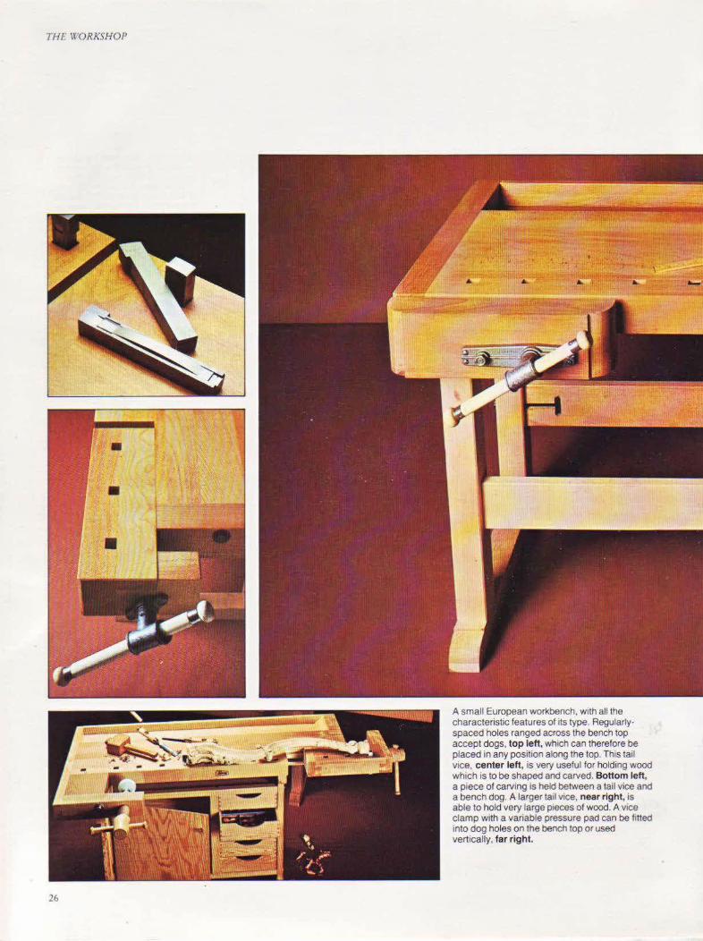
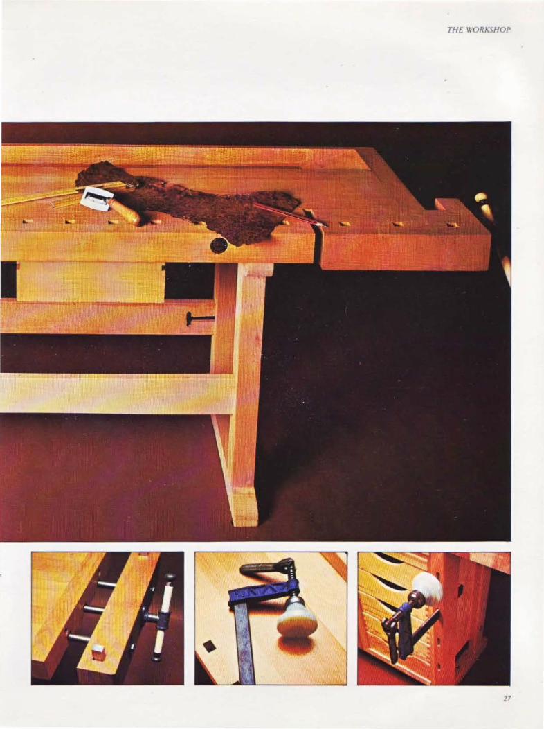
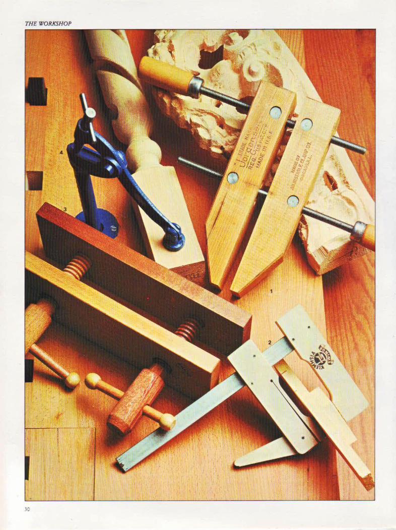
A small European worl<bench, w1th all the characteristic features of its type. Regularly· spaced holes ranged across the bench top accept dogs, top left, which can therefore be placed in any position along the top. This tail vice, center left, is very useful for holding wood which is to be shaped and carved. Bottom left, a piece of carving is held between a tail vice and a bench dog. A larger tail v1ce, near right, IS
able to hold very large pieces of wood. A vice clamp with a vanable pressure pad can be fitted into dog holes on the bench top or used vertically, far right.
THE\\ OR!I:SHOP
27

TH£ WORKSHOP
2,---------------------------------------------------------~
5
with the vice dog, accept similar dogs. Thus, any length of timber can be held between the dogs, using rhc vice to give rapid tightening. These vices usc metal screws, the dogs being of wood, plastic or metal. The side vice is generally made of metal, and is available in plain screw, or alternatively, is fitted with a quick-
28
3
release lever for rapid adjustment. The holding of timber for carving or
sculpting will require rhe addition of a bench holdfast or carver's screw. Both these are fitted into a hole in the bench top. The holdfast consists of a shaft, with a lever arm pivoted at the top actuated by a screw. The lever arm has a
swivel shoe which is placed on the work, and through which pressure is applied. The manufacrurcr supplies two metal collars which can be inserted inro the bench top, just below the surface, to house the holdfast and .save wear and tear of the bench top itself. Ir is also useful to have a collar inserted near the

top of the right-hand leg of the bench, to allO\\ .tdditional support for long timbers held in the side vice.
The woodcarver's screw, designed to
hold wood when it is being carved on each side, is screwed into the underside of the workpiece and passed through the hole in the bench. A wing nut is appli~d
to the screw from below to !>ecure it. Most individual need~ can be met
with these traditional tools, but the woodworker will find himself improvising from time to time tO solve a particular problem. G damps (C clamps) u~cd with the bench top or vice, often ~olve the problem.
THE WORASifOP
1 A selection of some of the clamps which are available. 2 Edging clamps in use, showing thetr ability to grip strips on straight or curved wor1<. 3 A lrght-duty clamp for one-handed use. 4 Clamp heads make a bar clamp of any length. 5 T·bar clamps in use They are made of section steel to restst bending when they are being used 6 Large G clamps holdtng several pteces of wood together. 7 Mitre clamps hold picture frames securely when they are being glued.
Where space pennits, a side benlh IS
usefuL Bo:>.ed oilsrones need a home and, since they are constantly in use. a location on a purpose-designed side bench will avoid frustration and sa' e time. Small electric tools such a5 the grinder and drill can be hou~ed in the same way. These benches need not have
29
THE WORKSHOP
30

heavy tops, and any available timber can be used.
The sawing of planks and sheets can only be carried out satisfactOrily using sawing trestles. These, if made in the traditional way, have splayed legs and need storage space. There are, however, a number of patented devices, made of metal, requiring 3X2 inch/75X50mm or
Apart from the traditiOnal clamp, there are clamps lor lighter work. some of whiCh are Illustrated on these pages. Left: 1 A wooden hand screw with jaws that close at a vanety of angles. 2 A light clamp used lor veneering or light glUing but which can also exert great pressure. 3 Beech bench v1ce surtable lor light work. 4 A bench holdlast wh•ch can be clamped to any workbench and •s especially useful in low-rehel carving. This page : Above, the speed clamp IS a new design in bar clamps, with both head and tail sliding along the bar; above right, two fixtures lit onto any ~4-ineh/18-mm standard threaded pipe to make a firm clamp which works hke a C clamp but 1s much faster to open and close. far right, small, general-purpose spring clamps near right, hghtwe!Qht shding head clamps
4X2 inch/100X50mm timber legs which are easily removable and will require less storage space. Trestles made with hinged tops also take up less space.
A bench which doubles as a trestle is the ever-popular Black & Decker \X'orkmate. This is J\ailablc in se,eral heights, and it~ top serves also as a \·ice. It can be folded flat and hung on a wall-
THE WORKSHOP
the ideal solution for the woodworker with a space problem.
Select your bench with care, and think ahead if possible, to forecast the problems it may need to solve. Comider tt too as a partial solution to \our storage problem, and remember that you may regret for all-time a poorquality or inferior selection.
31

TilE \t'ORKSHOP
Choosing Your Tools Ob\'iously, the choice of tools will depend upon the panicular craft, but the selection of the right tools of the right quality is fundamental. The quality of the tool, 'vith regard to destgn and material, must over-ride all other consider.nion!>. A certain number ot hand tools, such as saws, planes and chisels, are essential tO the basic kit. Look for those carrying well-known brand names, which invariably carry a maker'~ guarantee. One or two portable po'' er tools, together with stationary machines, mav be useful additions, bur should be sel~cted with their likeh use in mind. Where weighty or bulky timbers are to be used, it may be necessary to give priority to po;table power.
n1c exploration of timber through hand tools must be the path that the true craft~man will follow. It is only in this wav that he can trulv discover timber; probably the most b~autiful of the raw materiab man can fashion. It i!> onh possible to appreciate the problem!> o(a machine in cutting and shaping wood if one ha:. carried out the !lame work fir\t using hand tools. This is the an!>wer to those people who tend ro say, often quite strongly, that the use of hand rools will gradually decrease unti l power tools t:lke over completely. Thi~ may well apply tO large area:. of industry but can never apply to rhe serious home craftsman, the craftsman earning his living ill a true craft or the student in college or uni,·ersity.
Qual!ty work will almost invariubly <;pring trom a ound knowledge of the
3.!
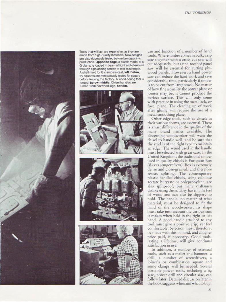
Tools that wi ll last are expens1ve, as they are made from high·quahty matenals. New designs are also rigorously tested before being put into production. Opposite page, a plastic model of a G clamp is loaded in beam of light and observed through a polanz1ng screen to test 1ts strength. A shell mold for G clamps 1s cast. lefl Below, try squares are meticulously tested for square before leav1ng the factory A wood·bonng tool IS
forged, below m iddle. Ch1sel handles are turned from boxwood logs, bottom.
THE WORKSHOP
use and function of a number of hand tools. Where timber comes in bulk, a rip saw together with a cross cut saw will cut adequately, but a fine-toothed panel sa" \\-ill be e~~cntial for cuttin~ plywood panels. Howe\ er, a hand pO\\ er ~aw can reduce the hard work and 3\'C
considerable rime, particularly if rimbc!r is to be cut from large srock. No matter of how fine ,1 quality the power plane or jointer may be, it cannot produce the perfect surface. This will only come with practice in U\ing the metal jack, or fore, pbne. The deaning up of work after gluing will require the u<;c of a metal ~moothing plane.
Other edge tools, such as chi<;els in their various fom1s, are essential. There is a vast difference in the qualit) of the many brand names available. The discerning woodworker will want till' chisel co handle well, and be sure that the steel is of the right rype to maint.tin an edge. The wood used in the handle must be selected ~·ith great care. In the United Kingdom, the traditional timber used in qualit\ chisels is European Bo' (811xus sempen.1rens' . Box i extremely dcn\C and clme-gr.llncd, and therciore resists :.plining. The contcmpora!J plastic-han<.llcd chisels, using cellulose acetate butyrate or polrprop.ylene, are also splitproof, but many craftsmen dislike u~ing them. The)' haven't rhe feel of wood and can abo be slippery to hold. The handle, no matter of what material, muo;t be designed to fir the hand of the woodworker. Its shape must take into account the various cut'> it makes when held in the right or left hand. A good handle attached to .my tool must ~i\ e a po\iti\·c grip, yet fed comfortable. Selection mu~t. therefore, be made with this in mind, and a higher price paid, if nece!>sary. Good roob, lasting a lifetime, will give continual sari sfacrion in use.
In addition, a number of essential tool,, \ut:h a' a mallet and hammer, a drill, a number of scrcwdri,·er), .1
joiner's or combination square and some clamps \\ill be needed. Se\ eral portable power tools, including a jig saw, power drill and circular saw, can follow later. Det,liled discussion later in the book 'uggc't' \\hen and what to bu\ .
• 33
.H
CHAPTER THREE
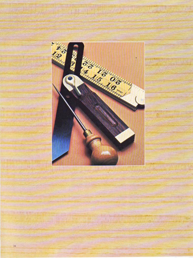
Measuring and ·
After selecting and preparing timber, measuring and
marking tools will be needed to mark lines for joints and
sawing, and for testing for true.
35

MARKING AND MEASURING
A .TER DF~IG"l<G AND PLANNING
a particular project, the timber must be selected and prepared. The preparation may entail sawing and planing, al though the extent of the latter may be reduced by the use of man-made boards or preplaned material. From the outset, however, measuring and marking rools will be needed, nor only for measuring and marking lines for joints and sawing, bur also for testing for true.
Usually, the woodworker will have ready a detailed drawing or sketch, " 'ith measurements added, from which tO
work. A cutting list is usefuL and "ill ease the work of timber preparation. The rransfer ing of drawing derail to the timber may often appear tedious, but it is a vital stage and one which must not be carried out hurriedly or carelessly. The accuracy of each mark made will depend upon that of a previously-made one, otherwise an accumulation of errors will result in a waste of time and materials. All joints must be marked out accurately and checked to ensure a perfect fit before sawing.
Accurate, well-made tools are vital to ensure perfection in the lay-out st;tge, and they will always be needed- even in the smallest project. Expensive though
·they may be, they will pay dividends in the long run.
Rules and Tapes On both sides of rhc Atlantic, the traditional measuring tool for the average woodworker has been the 2-foot folding rule, although the joiner and carpenter has favored the 3-foot folding rule. Since rhe onset of the metric system, both of these arc grndually being superseded b~r the metric rule, iQ a 4-fold style. The foot rules usually had regular markings as small as lft6 inch completely along borh edges of one side, with 1fs inch markings . on the reverse.
A good folding rule will be constructed of boxwood, with brass firrings. Boxwood was chosen because of its close grain and hard-wearing qualities. However, it is becoming very difficult to obtain, and substitute boxwoods are being used. A number of manufacturers are now using plastics,
36
the most popular one being makrolon, wich stainless steel fittings.
ln countries where Imperial measurements are being phased out, a combination of Imperial and metric can still be found. Some tradesmen, particularly in _ orth America, require a rule of greater len~th than that pro\·ided by the fourfold _rule. The zig-zag rule meets this requtrement.
It was made in boxwood originally, but several steel versions arc now available. A variation of the wooden zig-zag, called an extension rule, has a slide inserted on one arm to take the inside measurements of frameworks and other constructions.
Perhaps the most versatile of the measuring tools is the flexible tape. These tapes were made of linen once, and cased in leather, bur rhe contemporary type is generally of flexible sreel in a metal case. They are ideal for measuring in the flat or in the curve, since they can be wrapped around the object. Measuring out using a steel tape often gives more accurate results than when a thick wooden rule is used, because the tape is flatter and lies closer to the object being measured. The majority of tapes are divided into inches down to Va inch on one side and in meters down to millimeters on the other. These rules should be handled with care, and a spot of oi l- or a rub down with an oiled cloth will keep them in good condition.
The two-fold steel rule is popular also amongst tradesmen, and is available in
Caliper gauges are finely graduated; the larger gauge above can take both inside and outside measurements. Below: Measuring the circumference of a tube using a flexible tape.
both Imperial and metnc measurements .
One-piece steel rules can be useful sometimes. However, they arc designed for the engineer who needs to rake very small mcasuremen~. They arc obtainable in lengths of 6, 12, 24 and 36 inches, as well as 300mm and 1m.
C alipers Although not the most important of the measuring tools, there are times when calipers arc indispensable, such as when raking inside or curved measurements.
Calipers are usually made from highquali ty steel, the legs being held fimuy in any position by their hinge pin. This type can often be upset by the slightest pressure so, if they arc to be used a great
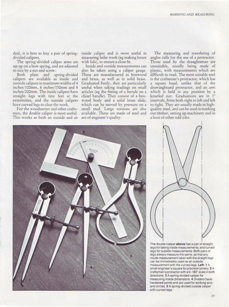
deal, it is best to buy a pair of springdivided calipers.
The spring-divided caliper arms are set up on a bow spring, and arc adjusted to si7c by a nut and screw.
Both plain and spring-divided caliper~ are available as inside and outside calipers in maximum width~ of 4 inches/ lOOmm, 6 inches/ ISOmm and 8 inches/200mm. The inside calipers have straight legs with tiny feet at the extremities, and the outside caliper~ ha' e curved legs to dear rhe work.
I·or the woodrurncr and other craftsmen, the double caliper is most u~eful. This works as both an outside and an
inside caliper and is most useful in measuring lathe work ( eg making boxes with lids), to ensure a close fit.
Inside and outside measurements can abo be taken using a caliper gauge. The'>e are manufactured in boxwood and brass, as well as in solid brass. Graduated finely, they are particularly useful when taking readings on small articles ( eg the fitting of a ferrule on a chisel handle). They consist of a boxwood body and a solid brass slide, '' hich can be mo,·ed b) pressure on a \mall srud. Large "ersions are abo available. These arc made of steel and are of engineer's quality.
MAR/1.1\G AND MEASURI'\G
The measuring and transfering of angles calls for the use of a protractor. Those used by the draughtsman are unsuitable, usually being made of plastic, with measurements which are difficult to read. The most suitable tOol is the craftsman\ protractor, which has a square head, unlike that of the drawingboard protractor, and an arm which is held in anr position by a knurled nut. Graduations are in 1° intervals, from both right to left and left to right. They are usually made in highquality steel, and can be used in marking out timber, setting up machinery and in a host of other odd jobs.
The double caliper above has a pair of strrught legs for taking 1ns1de measurements, and curved legs for outside measurements. Both pa1rs of legs always measure the same, so that any 1ns1de measurement taken w1th the stra•ghtlegs can be immediately used as an outs1de measurement wnh the curved legs. Left: 1 A small eng1neer s square for prec1s1on JOinery 2 A craftsman's protractorwtth a o-1ao• scale 1n both directions. 3 A spnng-dtVided caliper for measuring Inside d1mens1ons. 4 Dividers have hardened points and are used for scribing arcs and circles. 5 A spnng-d1v1ded outside caliper w1th curved legs
37

MARKING AND MEASURING
Above: 1 A steel adjustable combination square with a spirit level and graduated blade. 2 A steel sliding bevel. 3 Small sliding bevel with a brass blade. 4 An adjustable preCISIOn square with a spirit level set in the stock·and a graduated blade.
38

1
: ~~:~~~m~
MARKI\C AND MEIISC.,'RI.\'C
Lett: 1 A flexible steel tape rule. 2 A general· purpose knife w1th replaceable blade 3 45• square for mark1ng m1tres. 4 A comb1nation try square and mitre square. 5 Combined awl and marking knife. 6 Three-foot folding boxwood rule. 7 Two-foot brass smgle·fold rule. Below. a collect1on of squares. 1 A deluxe square w1th rosewood handle. Both 1nside and outs1de edges are fitted With dovetailed stoned m lied brass lac1ngs 2 A very ng1d try square. w1th a handle faced w1th solid brass. 3 A modelmaker's square with a 2-lnch/50-mm brass blade. 4 An African satinwood-bladed square With a precision-milled AfriCan Padauk handle. As the blade 1s 15 lnches/375mm long. 11 would be too heavy 1f made of metal. 5 A sohd brassbladed square w1th a Braz1han tuhpwood hand e It IS very useful for cabinetwork. 6 A shock-proof try square with a blade that runs the full length of the handle. It is 1mposs1ble to knock it acc1dentally out of square.

MARKiNG AND MEASURiNG
Squaring Tools The right angle, or 90° angle, is one which is vital to most constructional work. In fact, it is impossible to think of a woodworking construction which does not need the square. The jointing of timber almost invariably requires great accuracy in fitting shoulders, and shelves and doors must also fit exactly.
The try square is the basic squaring tool required for marking out and testing angles. It consists of a blade of steel accurately set at 90° in a wooden (or metal) stock. In the best-quality squares, wooden stocks are made of rosewood, and ate faced with brass to pre\·enr wear. They are usually available in 6-, 9- or 12-inch/ 150-, 225- or 300-mm blades, and a number are graduated in inches and millimeters. A goodquality try square has been precisiontested for accuracy, and is sturdily riveted to resist shock. The best type has an L-shaped blade, which extends the length of the hardwood stock.
On a number of squares the top of the stock is cut at 45°, so that mitres can be marked, eliminating the need for a separate tool.
A variation on the square is the mitre square. Designed to mark and rest mitres, the angle of 45° is fixed, with the blade fixed tO a hardwood stock.
Mitre squares arc also available in steel, but these are not widely used by woodworkers, who prefer to work with wooden ones. In recent years, the versatile combination square has become popular. Made with a steel or alloy stock, the steel blade slides along the Stock, which is faced at 90° and 45°. The blade is instantlr secured in any position. Generally it is marked jn tnches and millimeters. This tool can serve as a square, mitre square, depth gauge and, in conjunction with a pencil, it can be used as a pencil marking gauge. A number arc fitted with a small vial for use as a spirit level, and a small scribing pin for marking out. The woodworker's combination square shou ld not be confused with the engineer's version, which is a too~ of great precision and extremely expens1ve.
For the marking of any angle, and particularly the dovetail, the wood-
-10
Many-sided figures can be constructed using the angle divider. The body is marked for 4, 5, 6, 8 and 10 sides and 30•, 45•, and so· angles.
worker will need a sliding bevel. This tool has a hardwood stock and a sliding, slotted blade, which can be secured at any angle by either a slotted or winged screw. Tt is usual to set up the required angle on the edge of a board and align the bevel to that, or ro set it using a protractor.
In built-up work, either on the bench or lathe, the setting up of angles other than 90° or 45° presents a problem. The angle can be struck from a protractor
0
but this can often prove difficult and give unsatisfactory results. Often too, the woodworker has to transfer an angle from one piece of timber to another. The angle divider is the answer, the steel arms and body can be locked into any position and set to accurately marked graduations. The graduations give settings from 4-, 5-, 6-, 8- and 10-sided figures, as well as 30°, 45° and 60° bisected angles. It is not an essential tool for the average kit, but nevertheless a
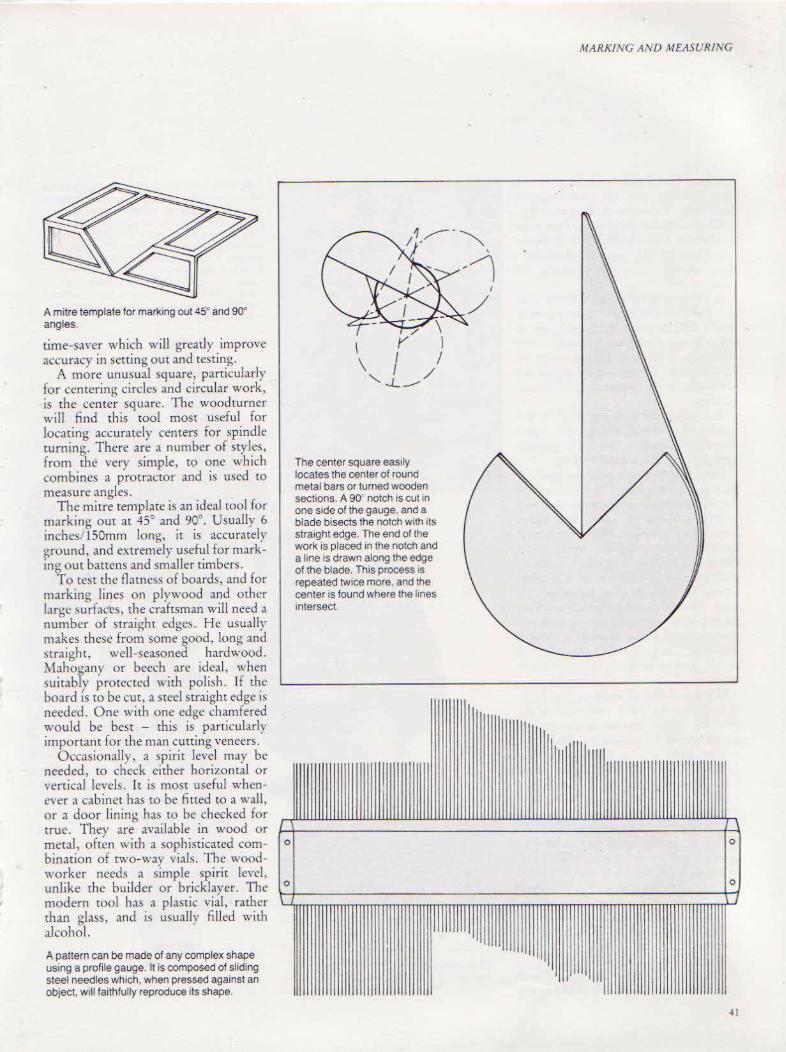
A mitre template for marking out 45° and 90° angles.
time-saver which will greatly improve accuracy in setting out and testing.
A more unusual ~quare, particularly for centering circles and circular work, is rhe center square. The woodturner will find this tool most useful for locating accurately centers for spindle turning. There are a number of styles, from the very simple, t9 one which combines a prorractor and is used to measure angles.
TI1e mitre template is an ideal rool for marking out at 45° and 90°. Usually 6 inches/ 150mm long, it is accurately ground, and extremely useful for marking out battens and smaller timbers.
To test the flames~ of boards, and for marking lines on plywood and other large surfaces, the craftsman will need a number of straight edges . He usually makes these from some good, long and straight, well-seasoned hardwood. Mahouany or beech are ideal, when suirabfy protected with polish. If the board is robe cut, a steel straight edge is needed. One with one edge chamfered would be best - this is particularly important for the man cutting veneers.
Occasionally, a spirit level may be needed, to check either horizontal or vertical levds. It is most useful whenever a cabinet has tO be fitted to a wall, or a door lining ha~ to be checked for true. They are available in wood or metal, often with a sophisticated combination of two-war vials. The woodworker needs a simple spirit level. unlike the builder or bricklayer. The modern mol has a plastic vial, rather than glass, and is usually filled with alcohol.
A pattern can be made of any complex shape using a profile gauge. lt is composed of sliding steel needles which, when pressed against an object, will faithfully reproduce its shape.
0
0
\ \
The center square easily locates the center of round metal bars or turned wooden sections. A 90 notch rs cut in one side of the gauge, and a blade bisects the notch with its straight edge. The end of the work is placed in the notch and a hne is drawn along the edge of the blade. This process is repeated twice more, and the center is found where the hnes rntersect.
I
llllllllllll ll
MARKING AND MEASURING
0
0
J
41
MARKING AND MEASURING
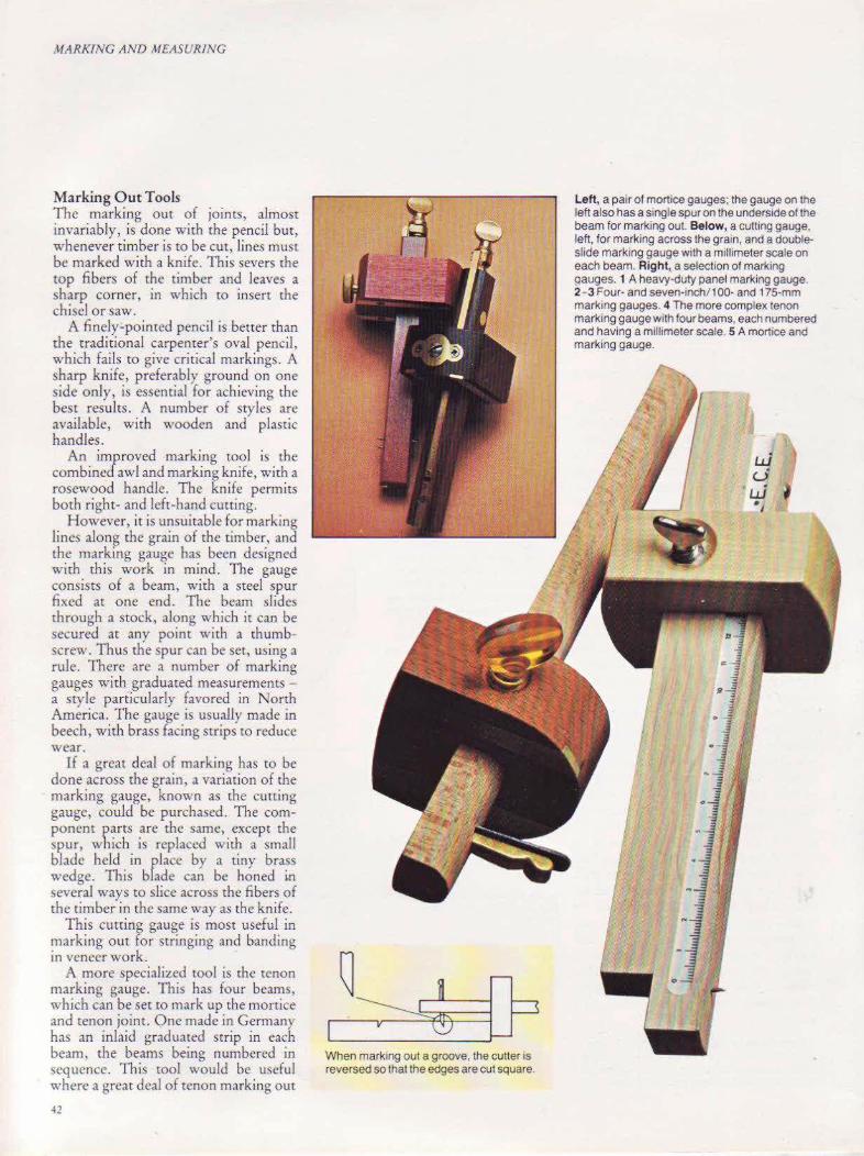
Marking O u t Tools The marking out of JOints, almost invariably, is done with the pencil but, whenever timber is to be cut, lines must be marked with a knife. This severs the top fibers of the timber and leaves a sharp corner, in which to insert the chisel or saw.
A finely-pointed pencil is better than the traditional carpenter's oval pencil, which fails to give critical markings. A sharp knife, preferably ground on one side only, is essential for achieving the best results. A number of sty les arc available, with wooden and plasric handles.
An improved marking tool is the combined awl and marking knife, with a rosewood handle. The knife permits both right- and left-hand cutting.
However, it is unsuitable for marking lines along the grain of the timber, and the marking gauge has been designed with this work in mind. The gauge consists of a beam, with a steel spur fixed at one end. The beam slides through a stock, along which it can be secured at any point with a thumbscrew. Thus the spur can be set, using a rule. There arc a number of marking gauges with graduated measurements -a style particularly favored in North America. The gauge is usually made in beech, with brass facing suips to reduce wear.
Tf a great deal of marking has to be done across the grain, a variation of the marking gauge, known as the cutting gauge, could be purchased. The component parts are the same, except the spur, which is replaced with a small blade held in place by a tiny brass wedge. This blade can be honed i.n several ways tO slice across the fibers of the timber in the san1e way as the knife .
This cutting gauge is most useful in marking out for stringing and banding in veneer work.
A more specialil.ed roo! is the tenon marking gauge . This has four beams, which can be set to mark up the mortice and tenon joint. One made in Germany has an inlaid graduated strip in each beam, the beams being numbered in sequence. This tool would be usefu l where a great deal of tenon marking out
-11
When marking out a groove, the cutter is reversed so that the edges are cut square.
Lett, a pair of mortice gauges; the gauge on the left also has a single spur on the underside of the beam for marking out. Below, a cutting gauge, left, for marking across the grain, and a doubleslide marking gauge with a millimeter scale on each beam. Right, a selection of marking 9auges. 1 A heavy-duty panel marking gauge. 2- 3 Four- and seven-lnch/1 00· and 175-mm marking gauges. 4 The more complex tenon marking gauge with four beams, each numbered and having a millimeter scale. SA mortice and marking gauge.

MARKING AND MEASURiNG
is to be done. The only alternative to this would be to use a number of separate marking gauges, numbered to ensure correct order of use.
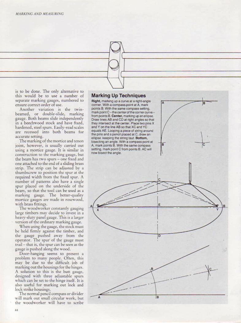
Another variation is the twinbeamed, or double-slide, marking gauge. Both beams slide independently in a beechwood stock and have fixed, hardened, steel spurs. Easily-read scales are recessed into both beams for accurate sctung.
The marking of the mortice and tenon joint, however, is usuaUy carried out using a morrice gauge. It is similar in construction to rhc marking gauge, bur the beam has two spurs -one fixed and one attached to the end of a sliding brass strip. The strip can be adjusted by a thumbscrew to position the spur at the required width from the fixed spur. A number of patterns also have a single spur placed on rhe underside of the beam, so that the roo! can be used as a marking gauge. The better-quality morrice gauges are made in rosewood, with brass fittings.
The woodworker constan tly gauging large timbers may decide ro invest in a heavy-dury panel gauge. This is a larger version of the ordinary marking gauge.
When using the gauge. the stock must be held firmly against the timber, and the gauge pushed away from the operator. The spur of the gauge must trail- that is, the spur can be seen as the gauge is pushed along the wood.
Door-hanging seems to present a problem to many people. Often, this may be due to the difficult. job of marking out the housings for the hinges. A solution to this is the butt gauge, designed with three adj ustable spurs which can be set to the hinge itself. It is also useful for marking om lock and Jock strike housings.
The normal pencil compass or divider will mark out small circular work, but the woodworker will have to scribe
Marking Up Techniques Right, marking up a curve at a right-angle corner. With a compass {Joint at A, mark points B. With the same compass setting, mark point C- the center of the corner curvefrom points B. Center, marking up an ellipse. Draw lines AB and CD at right angles so that they intersect at the center. Place two pins X and Yon the line AB so that XC and YC equals AE. Looping a piece of string around the pins and a pencil placed at C, draw an ellipse keeping the string taut. Bonom, bisechng an angle. With a compass point at A, mark points B. With the same compass setting, mark point C from points B. AC will now bisect the angle.
D
A
8

MARKIV6 AND MEASUR/XG
--IQ..,___ _____ _._.,
______.01--------------"-l
A pair of trammel heads are attached to a beam to scribe large circles.
large circles from time to time. A beam compass, which i~ fined with a pair of trammel heads, will be useful. These heads slide along either a steel or "·ooden beam, can be fixed in am: position, and are both fitted with hardened steel pins. One serves as the compass point, and the other pin can be used to scribe the circle, or a pencil can be substituted. One pattern has the pins fitted so that they can be set at an angle to mark out circles in difficult positions.
Another variation of chi~ tool is the combined trammel and panel gauge. The trammel heads slide on two rods or beam'> and can be fixed in any position with knurled sere'' s. A fence which again slides along the rod~ converts rhc tool inro a panel gauge. This is a superb tool, particularly useful for marking our large panels of plywood and other manmade boards.
Above, a combination trammel and panel gauge. The fence and trammel heads can be moved to any pos1t1on along the rods. Large c~rcles can be scribed using the trammel heads alone or, with the fence attached, large panels can be marked up. Left, the butt gauge, a spec1al marking gauge for marking out the housings for door hinges and lock and lock strike hous1ngs.
Oft~n the center punch is regarded ,\\ a tool lor the metah"orker, but it can be used for marking out in wood and other materials. It is particularly useful for positioning screws when hingeing, and when positioning other cabinetmaker's h.1rdware. The am·il is struck by a mallet to drive the tip of the punch into the wood. A bcner version of chi~ tool, caJled a catapunch, avoids th<: usc of a mallet. When the anvil is depressed, an in-built spring causes the rip of the punch to mark the wood. This is especially useful if the woodworker is holding another tOol in his other hand.
All these tools, well-selected and carefully used, will ensure a good start to any project. Guard them agam~t abuse, lightly oil those which may corrode and, at the same time, learn to appreciate the beauty of timber, from which many tools arc made.
-15

CHAPTER FOUR
Saws The saw
is an essential tool in the woodworker's kit,
and is vital when both preparing and working
with timber.
47
SA\VS
T. SAW" AN liSSENT!AL TOOL'" the woodworker's kit, and is vital when both preparing and working with the timber. Before choosing a saw, it is essential to understand its function, so that the correct saw is bought.
Basically, saws can be divided into three main groups - band saws (including panel saws) , back or tenon saws and special saws. Hand saws divide further into distinct types indicated by the design of the teeth - rip teeth and cross cut teeth. All saw teeth (usually called points) arc set alternately to rhe left and right, and when pushed through wood cut a groove called a kerf.
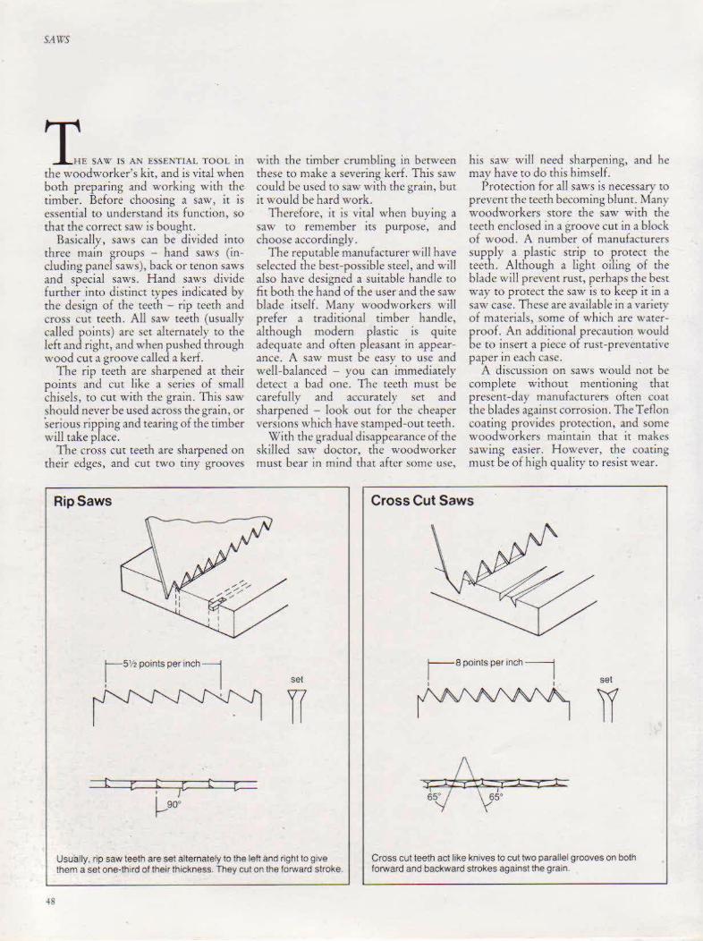
The rip teeth are sharpened at their points and cut like a series of small chisels, to cut with the grain. This saw should never be used across the grain, or serious ripping and tearing of the timber will take place.
The cross cut teeth are sharpened on their edges, and cut two tiny grooves
RipSaws
t
with the timber crumbling in between these tO make a severing kerf. This saw could be used tO saw with the grain, but it would be hard work.
Therefore, it is ,;tal when buying a saw to remember its purpose, and choose accordingly.
The reputable manufacturer wiiJ have selected the best-possible steel, and will also have designed a suitable handle to fit both the hand of the user and the saw blade itself. Many woodworkers will prefer a traditional timber handle, although modern plastic is quite adequate and often pleaslnt in appearance. A saw must be easy to use and well-balanced - you can immediately detect a bad one. The teeth must be carefully and accurately set and sharpened - look out for the cheaper versions which have stamped-out teeth.
With the gradual disappearance of the skilled saw doctor, the woodworker must bear in mind that after some usc,
his saw will need sharpening, and he may have to do this himself.
Protection for all saws is necessary to prevent the teeth becoming blunt. Many woodworkers store the saw with the teeth enclosed in a groove cut in a block of wood. A number of manufacturers supply a plastic strip to protect the teeth. Although a light oiling of the blade will prevent rust, perhaps the best way to protect the saw is to keep it in a saw case. These are available in a variety of materials, some of which are waterproof. An additional precaution would be to insert a piece of rust-preventative paper in each case.
A discussion on saws would not be complete without mentioning that present-day manufacturer5 often coat the blades against corrosion. The Teflon coating provides protection, and some woodworkers maintain that it makes sawing easier. However, the coating must be of high quality to resist wear.
Cross Cut Saws
set
r--s points per inch~
I I set
Usually. rip saw teeth are set alternately to the left and right to give them a set one-third of their thickness. They cut on the forward stroke.
Cross cut teeth act like knives to cut two parallel grooves on both forward and backward strokes against the grain.
48

Log Saws \X'hcrc large timbers have to be cut, and the woodworker is unable to employ the crviccs of the professional tree surgeon, a number of different saw!> can be u ed.
The two-man cross cut saw i~ superb for handling large logs. h comes in a variety of sizes and the teeth are interspersed with deep gullets to carry the sawdust. The best have a style of teeth
caJled lightning. The blade is curved so that the teeth can be kept in contact with the umber throughout the movcmem of the s.nv.
The one-man cross cu,t saw has a handle similar to that of the hand Sa\\
but with an additional round handle which can be placed anywhere along the top of the blade. Usually, it is placed at the top of the blade, near the handle, but the saw can be com ened into a twoman cross em saw by fixing the supplementary handle near rhe roc of the blade.
The contemporary log saw consists of a tubular steel frame with a saw blade bcrwccn 24- 36 inches/600-900mm long and 'o~-1 inch/ 18-25mm in width. The blade is tensioned either by screw or lever. This tool is most usefu l with pe_ggcd teeth and gullets, which cut efhcientlv in both directions. It can tackle .,.;anv rough conversion jobs \\ hich would be hard "'ork for the nornul hand sa\\.
A number of manufacturers fit the saw with a wrap-round handle. It is sometimes also known as the bushman's or forester's saw. The teeth on the one-man cross-cut, right, are hand-fried to give max1mum cut on push and pull.
The 'Great Amencan' tooth pattern, left sets of three deep lndentabons, which help to throw out the sawdust- has become 1ncreas1ngly popular for the log saw The modern versiOI'l IS Illustrated above, and the two-man cross-cut below.
SAWS

SAWS
H and Saws This group includes rip saws, cross cut saws and panel saws and, as previously de cribed, they are distinguished by the style of their teeth. Generally, hand s,l\\ s from reputable manufacturer~ are taper ground. This produces a blade which tapers from the handle to the toe on the back of the saw, but which retains a single thickness just above the teeth. This type of saw cannot bind in a deep cut, and the set of the saw need not be quite lS great as with an unground blade. The sa~· is easier to use, and s;wes wood.
A rip saw is needed to cut a piece of timber along its length- that is, with the grain. It is the longest of the hand saws, usually 28-30 inches 700-750rnm, with 31 ! points per inch/25rnm. Some rip sa" s can have smaller teeth at the toe thnn at the handle. There is also :1 halfrip vers ion, slightly shorter in length, with an extra point per inch/25mm.
The cross cut saw for cutting across the grain is between 22-26 inches/SSD-65Cmm in length and has 5 points per inch 2Smm.
The panel sa\\ is for finer work and useful for cutting thin plywood panels. Usually, it measures 20-2~ inches/S00-600mm in length, with 7 points per inch/25mm. There may be variations in de!iign between manufacturers, even in the length and number of points.
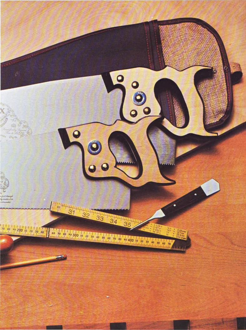
All good hand Sa\H will have handles <;ccured by brass screws- this is essential to take up any slack and ensure a perfectly tight union.
When ripp1ng (sawing with the grain), keep the saw at an angle of so•, and at 45• when cross-cutting (across the gra~n).
50
Points to look for when buying a Saw
- (
Flexibility: Although you should be able to flex the blade easily, its tension should quickly bnng it back to true.
Crown: The greater the crown, the fewer the teeth that make contact w1th the wood. An 1e-mch/3·mm crown on a 26·1nch/650·mm blade makes sawing easier without affecting efficiency.
Straightness: Before buying, check that the blade is qUite straight and lies properly in the handle.
Taper grinding: A taper-ground blade means that the teeth require less set and the blade w111 not bind in the kerl. The manufacturers specifications will tell you whether rt has been ground in this way.
Teeth : Sharpness. of course. 1s essential. Make sure also that the sellS un1torm and that there are no burrs on the teeth.
Handle: Check that the full four-finger grip is comfortable. Higher-quality saws usually have wooden handles. These will not make the hand sweat so much, and after a while they will begin to follow the contours of the hand.
Fittings: How is the handle secured? 1 Cheap screw fixing, 2-3 better and best shoulder screw fixing. Brass fitt1ngs are best, wh1ch may be nickel-plated.
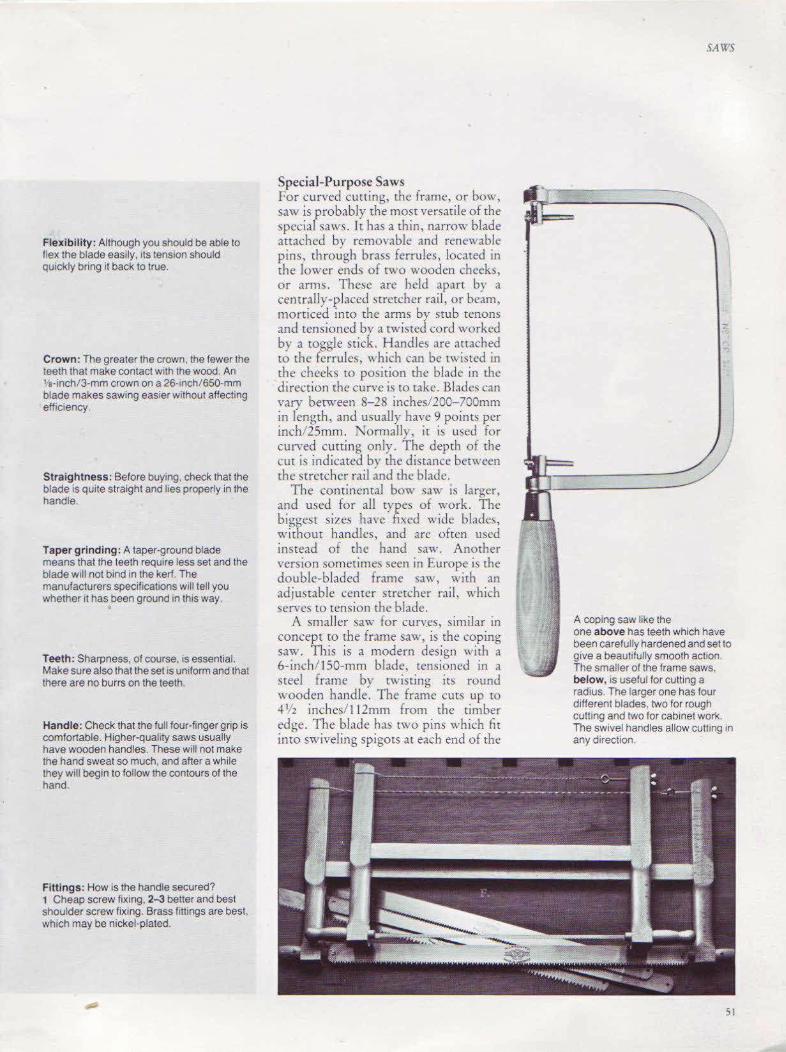
Special-Purpose Saws For curved cuuing, the frame, or bow, saw is probably the most versati le of the special saws . lt has a thin, narrow blade attached by removable and renewable pim, through brass ferrules, located in rhe lower ends of rwo wooden cheeks, or arms. Thc~e are held apart by a centrally-placed stretcher rail, or beam, morriced into the arms bv stub tenons and tensioned by a twisted cord worked by a toggle stick. Handles are attached ro the ferrules, which can be twisted in the cheeks to position rhc blade in the direction the curve is to rake. Blades can vary between 8-28 inches/200-700mm in Jengrh, and usually have 9 points per inch/ 25mm. Tormalk, it is used for curved cutting only. The depth of rhe cut is indicated bv the distance between rhe stretcher rall and the blade.
The continental bow saw is larger, and used for all types of work. The biggest s izes have fixed wide blades, without handles, and arc often used instead of the hand saw. Another version sometimes seen in Europe is the double-bladed frame saw, with an adjustable center stretcher rail, which serves m tension rhe blade.
A smaller saw for cun~es, similar in concept to the frame saw, is the coping saw. This is a modern design with a 6- inch/ J 50-mm blade, tensioned in a steel frame by C\\ isting its round wooden handle. The frame cuts up w ·l'/ 2 inches/ 112mm from the timber edge. The blade has two pins which fit into swiveling spigots at each end of the
SAW'S
A coping saw like the one above has teeth which have been carefully hardened and set to give a beautifully smooth action. The smaller of the frame saws, below, IS useful for cu tting a radius. The larger one has four different blades, two for rough cutting and two for cabinet work. The swivel handles allow cutting in any direction.
51

ClaSSIC handsaws. w•th both cross cut and np saw teeth are contrasted w1th the more unusual lookmg bow saw The saw case Will protect hand and tenon saws when not in use.
-
•f.•6fA-r ~~ .. ~~ .. ""'r
SA\\''S
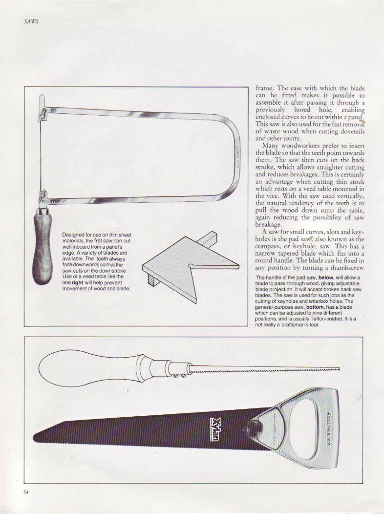
Designed for use on thin sheet materials. the fret saw can cut well inboard from a panel's edge. A variety of blades are available. The teeth always face downwards so that the saw cuts on the downstroke. Use of a veed table like the one right will help prevent movement of wood and blade.
frame. The ease with which the blade can be fitted makes it possible to assemble it after passing it through a previously bored hole, enabllng enclosed cun·es to be cut within a panel. This saw is also used for the fast remova1 of waste wood when cutting dovetails and other join1:s.
Many woodworkers prefer to insen the blade so that the teeth point towards them. The saw then cuts on the back stroke, which allows straighter cutting and reduces breakages. This is certainly an advantage when cutting thin stock which rests on a veed table mounted in the vice. With the saw used vertically, the natural tendency of the teeth is to pull the wood down onto the table, again reducing the possibility of saw breakage.
A saw for small curves, slots and keyholes is the pad sa' , also known as the compass, or keyhole, saw. This has a narrow tapered blade which firs into a round handle. The blade can be fixed in any position by turning a thumbscrew
The handle of the pad saw, below, wtll allow a blade to pass through wood, giving adjustable blade projection. It Will accept broken hack saw blades. The saw is used for such jobs as the cutting of keyholes and letterbox holes. The general-purpose saw, bottom, has a blade which can be adjusted to nine different positions, and is usually Teflon-coated. It is a not really a craftsman's tool.

The nest of saws, 1, has interchangeable keyhole and squared-off blades. The teeth on the upper edge of the flooring saw. 2, allow you to cut to the edge of a board from an upright posit1on
located in the handle ferrule. Blades vary between 5-15 inches, J25-375mm in length, and from 8- 10 points per inch 25mm. The handles of many pad )a\\ s also take a whole or broken hack-• w. blade.
The pad saw blade i~ seen again in the: nest of s,tws. This comprises one openended handle into which various tapered blades, slotted at the wide end, can be fitted. This is a useful tool for the ca,ual woodworker.
An e:-.tremely versatile saw for fine work, particularly the piercing of thin panels and plywood, i!> the fret saw. It wa a craze amongst schoolboys in Europe in the early part of the twentieth century. A number of versions are still available, with frames up to 20 inches/ 500mm deep, allowing cuts to be made inboard from the edge of the panel. The
very fine blade, up to 6 inches/ ISOmm in length, is held in position by a clamp, with the tension applied through a thumbscrew. Different blades can be obtained for cutting wood, metal or plastics .
The hole saw, although not strictly in the saw family, i~ a very useful tool. This consists of a circu lar body and a drill bit, which firs intO the chuck of a portable drill. Circular blades arc .fitted mto the body and the portable drill switched on, once the drill bit has been correctly located on the materiaL Various si7e of blade~ .tre available, enabling holes robe cut in timber, metal and plastic.
For the craftsman working on a house, particularly when needing to gain access under floorboards for electrical or heating work, a special
The hole saw has a cylindrical saw blade w1th a dnll bit through Its center It will make holes 1n various metals as well as wood and plastic If you use an electnc dnll. remember that the outer saw w111 move much faster than the central drill b1t
flooring ~aw can be used. The blade IS 13 inches/325mm long, with 7 points per inch '25mm. The top side of the blade is angled to allow the saw to be used in an upright posicion close to a corner. The other edge ha!> teeth completely along it, anti is curved to cut into the tOngue of the floorboard without rhe need for a starring hole. Another version of rhi!> tool is the plywood saw, approximately 11 inchcs/275mm long. The end of the top edge is curYed and toothed, thus permitting cutting into a panel without pre-boring.
A fairly ne" addition to the a\\ family i~ one which is fitted with a IO\\
friction blade, capable of cutting wood, steel, plastics, rubber and many other materials. The blade is set in an enclosed hand lt:, and can be moved into mm: different positions.
55

SAWS
Back or Tenon Saws There are various r:ypes of saws in rhis group. Generally, the blades can be described as thin, short and rectangular in shape, with fine teeth finely set. A heavy strip of either brass or steel is folded over the back of the saw to strengthen it. Brass, being a heavier metal, is better than steel. The design of the saw means that it cannot penetrate the timber completely, making it suitable for cutting joints. The handle, similar to that on a hand saw, is often set higher, and is either closed or open. A smaller back saw, with an open handle, is known as a dovetail saw. It is 8 inches/ 200mm long, with as many as 26 points per inch/25mm. The bhde is extremely thin, with finely-set teeth to give complete accuracy in the cutting of dovetail joints and other fine work.
Tenon saws arc usually between 10-14 inches/250-350mm in length, with up to 20 points per inch/25mm, and arc used to cut tenon joints.
Another variation of the back saw is the gent's back saw, so-caJied after the small tools once used by gendemcn who rook up woodworking as a hobby. This has a turned chisel-like handle, with blades up to 10 inches/250mm long. The blade is thin, with small teeth, set to cut a narrow kerf. It is used best for cutting fine joints and dovetails. This saw has also been called the daney gent's ~aw, the gent's dovetail saw and the beading
56
saw. Many users find this saw difficult tO hold after using a saw with a normal handle. A continental manufacturer offers the gent's-sr:yle saw w ith an offset handle, and one with a reversible offset handle.
A variation of the gent's back saw is the blitz saw. This has interchangeable blades for use on metal, wood or plastics. A small hook as an appendage at the end of the back strip serves as an extra handle. It was not originally designed specifically for the woodworker, but was an all-purpose saw.
Ancillary Sawing Equipment Many sawing jobs can be carried out with the timber held in a vice, bur the sawing of tenon shoulders, and many other small er, shallower cuts in thinner timber, will be done best using a bench hook. This is a traditional piece of equipment in the United Kingdom, consisting of one large block of wood with an end block fixed on either side. Generally, it is made of beech with the end blocks doweled to prevent any possibili ty of the saw striking screws or nails. The bench hook is usually held in
The classic brass-backed gent"s saw, 1-2, is shown on the facing page. Derivations of this. with fixed offset handle, top, reversible offset handle, middle, and straight handle, bottom, are shown below. 3-4, facing page, are the blitz saw and slotting saw, useful for fine work. The back or tenon saw, 5, cuts smaller pieces to length. 6,the dovetail saw.

SA\t:S
57

5A IJS
Making a Sawing Sizing Board The stzing board Illustrated here IS a s1mple but reliable and efficient way of ensuring that a length of wood IS cut in completely equal s1zes. The base 1s made from 1 2 mch/12mm blackboard, w1th a renewable hardwood 1nsert to protect the base The upnght section ts made from beech or any other hardwood % x 1 ~ lnches/16 x 45mm. It has a sliding hardwood stop which can be fastened with a coach bolt and wing nut.
Dimensions 10 tnches/mm
A 18/ 450 H V2112 B 8/200 J ••t,./ 21 c %116 K ~./18
0 71'2/ 187 L 21•/58 E 3.•110 M ,.,,.124 F 1/25 N n.t 45 G 3.•1 19 0 ~/10
~F L_.r' --4---------~------+-~~~--------~
~-~~~==~==~*4====~~~====~~~t=H~ i_-~----------~-------r.~----------~~-L----------~ H ,-
..+... : Ill -;-I I
~ ~ I "'
I
£ Q)
:0 B Ill ~ Q) c Q)
a:
I Sliding Stop Half Full Size
~--------------------------- A--------------------------~
Scale- V• Full Size
;g
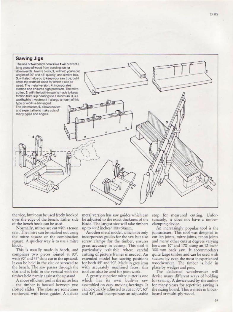
Sawing Jigs The use of two bench hooks hke 1 will prevent a long piece of wood from bendmg too tar downwards. A mrtre block, 2, wrll help you to cut angles of 90° and 45 qurckly, and a mitre box 3, wrll also help you to keep your saw true, but rt hmrts th,a wrdth of wood for whrch 11 can be used. The metal version, 4, incorporates clamps and ensures high precrsron. The mrtre cutter, 5, wi th the burlt-rn saw is made to keep friction from slip bearings to a minimum. It is a worthwhile investment rl a large amount of this type of work is envrsaged The 10mtmaster. 6, allows novrce and expert alike to make cuts of many types and angles.
I I L
the vice, but it can be used freely hooked over the edge of the bench. Either side of the bench hook can be used.
Normally, mitres are cut with a tenon sa" . The mitre can be marked out using the mitre square or the combination square. A quicker way is ro use a mitre block.
This is usually made in beech, and comprises two pieces jointed at 90°, with 90° and 45° slots cut in the upstand. It can be held in the vice or screwed to the bench. The saw passes through the slot and is held in the vertical with rhe timber held firmly against the upstand.
A more efficient tool is the mitre box - the timber is housed berween two slotted slides. The ~lot!> are sometimes reinforced with brass guides. A deluxe
metal version has saw guides which can be adjusted to the exact thickness of the blade. The largest ~iz.c will take timbers up to 4X2 inches/ 100X50mm.
Another metal model, which nor only incorporates guide\ for the saw but also crew clamps for the timber, ensure!.
great accuracy in cutting. This tool is particularly valuable where careful cutting of picture frames is needed. An extended model has sawing positions for both 45° and 90°. Made in grey iron '' ith accurately machined faces, this tool can also be used for joint work.
A greatly superior mitre cutter is one which has irs own built-in saw assembled on easy-mo,·ing bearings. It can be quickly adjusted to cut at 90°, 60° and 45°, and incorporates an adjustable
\'A\t''S
stop for measured cutting. Unfortunately, it does not have a timberclamping device.
An increasingly popular tool is the joinrmaster. This tool was dcsi!-\ncd to cut lap joints, mitre joints, tenon joints and many other cuts at degrees \'ar) ing between 10° and 170° using an 12- inch 300-mm back saw. Tt accommodates quite large timber and can be used with success by even the most inexperienced woodworker. The timber is hciJ in place by wedges and pins.
The dedicated woodworker ''ill devise many different ways of holding for sawing. A device used by the author for many years for repetitive sawing is the sizing board. This is made in blockboard or multi-ply wood.
59
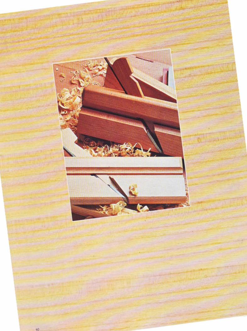

CHAPTER FIVF
Planes Planes are used to
prepare the surface of timber, for cutting joints and cleaning
up finished work .
61
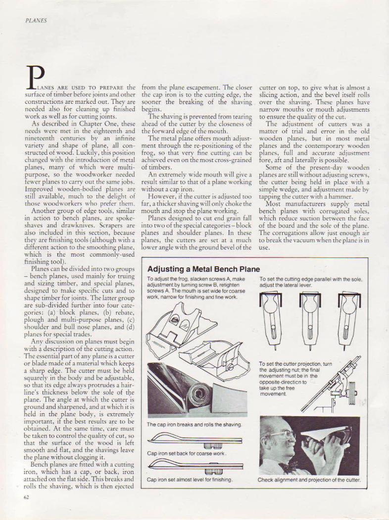
PLANES
E NES AR< U>ED TO PREPARE <he surface of timber before joints and other constructions are marked out. They are needed also for cleaning up finished work as well as for cutting joints.
A described in Chapter One, these needs were met in the eighteenth and nineteenth centuries by an infinite variety and shape of plane, aU constructed of wood. luckily, this position changed with the introduction of metal planes, many of which were multipurpose, so the woodworker needed fewer planes to carry out the same jobs. Improved wooden-bodied plane:. are still availabl e, much ro rhe delight of those woodworkers who prefer them.
Another group of edge tools, similar in action to bench planes, are spokesha\'CS and drawknives. Scrapers are also included in this section, because thev are finishing wols (although wirh a different action to the smooching plane, which is the most commonly-used finishing tool).
Planes can be divided into two groups - bench planes, used mainly for truing and sizing timber, and !>pecial plane~, designed to make '>pecific cuts and to shape timber for joints. The latter group are s ub-divided further into four categories : (a) block planes, (b) rebate, plough and multi-purpose planes, (c) shoulder and bull nose planes, and (d) planes for special trades.
Any discussit1n on planes must begin with~ description of the cutting action. The essential part of any plane is a currer or blade made of a material which keeps a sharp edge. The cutter must be held squarely in the body and be adjustable, so that its edge alway protrudes a hairline' thickness below the sole of the plane. The angle at which the cutter "is ~round and sharpened, and at which it is held in the plane body, is extremely important, if the best results are to be obtained. At the san1e tin1c, care must be taken to control the quality of cut, so that the surface of the wood is left smooth and flat, and rhe shavings leave the plane withour clogging ir.
Bench planes are fitted with a cutting iron, which has a cap, or back, iron attached on the flat side. This breaks and rolls the shaving, which is then ejected
62
from the plane escapement. The closer the cap iron is to the cutting edge, the sooner the breaking of the sha\·ing begins.
The shaving is prevented from 1earing ahead of the cutter by the closeness of the forward edge of the mourh.
The metal plane offers mouth adjustment through the re-positioning of the fro~, so that very fine cutting can be ach1eved even on the most cross-grained of timbers.
An extremely wide mouth will give a result stmilar to that of a plane working Rithout a cap iron.
However, if the cutter is adjusted roo far, a thicker shaving will only choke the mouth and srop the plane work ing.
Plane:; designed to cut end grain fall into two of the special categories- block planes and shoulder phme!>. In these planes, the cutters are ~et at a much lower angle with the ground bevel of the
cutter on top , to give what is almost a slicing action, and the bevel itself rolls O\·er the sha,'ing. These planes haYe narrow mouths or mouth adjustments to ensure the quality of the cut.
The adjustment of cutters was a matter of trial and error in the old wooden planes, bur in most metal planes and the contemporary wooden planes, fu ll and accurate adjusonent fore, aft and laterally is possible.
Some of the present-day wooden planes are still ,,·ithout adjusting screws, the ~utter being held in place with a simple wedge, and adjustment made by tapping the curter with a hammer.
Most manufacturers supply metal bench planes with corrugated soles, which reduce suction between the face of the board and the sole of the plane. The corrugations allow just enough air to break the vacuum when the plane ill in use.
Adjusting a Metal Bench Plane To adjust the frog. slacken screws A, make adjustment by turnmg screw B. retighten screws A. The mouth •s set wide for coarse work, narrow for fmish1ng and fine work.
The cap iron breaks and rolls the shaving.
Cap iron set back for coarse work .
e=5?: = Cap iron set almost level for finishing.
To set the cutting edge parallel with the sole, adjust the lateral lever.
To set the cutter projection, turn the adjusting nut: the final movement must be m the opposite<1irecticn to take up the free movement.
Check alignment and projection of the cutter.

Cross-Section of a Metal Bench Plane
Cross-Section of an Adjustable Wooden Bench Plane
Sole Cutter
Cap tron Spnng
Cutter adJUStment screw
Nut for tens10n adJUStment
63
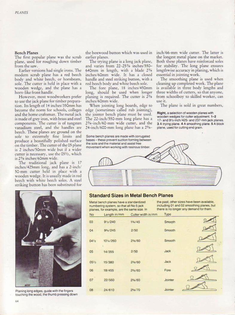
PLANES
Bench Planes The first popular plane was the scrub plane, used for roughing down timber from the saw.
Earlier versions had single irons. The modern scrub plane has a red beech body and white beech, or hornbeam, sole. The cutter is held in place wirh a wooden wedge, and the plane has a horn-like front handle.
However, most woodworkers prefer to use the jack plane for timber preparation. Its length of 14 inches/350mm has become the norm for schools, colleges and the home craftSman. The metal jack is made of grey iron, with brass and steel components. The cutter is of tungsten vanadium steel, and the handles are beech. These planes are ground on the sole to extremely fine limits and produce a beautifully polished surface on the timber. The curter of the 05 plane is 1 inches/ SOmm wide but if a wider cutter is necessary, usc the 05 112, which is 23fs inches/60mm wide.
The traditional jack plane is 17 inches/425mm long, and has a 2-inch/ 50-mm cutter held in place with a wooden wedge. It is usually made in red beech with white beech soles . A steel striking burton has been substituted for
Planing long edges, guide with the fingers touching the wood, the thumb pressing down
64
the boxwood button which was used in earlier planes.
The trying plane is a long jack plane, and varies from 22- 25:Ys inches/ 550-6 .. 0mm in length, with a blade 2Ya inches/60mm wide. It has a closed handle and steel striking button, with a red beech body and white beech sole.
The fore /lane, 18 inches/450mm long, shoul be used when longer planing is required. The cutter is 23fs inches/60mm wide.
When jointing long boards, edge to edge (sometimes called rub jointing), rhe jointer bench plane must be used. The 22-inch/550-mm long plane has a 23/s-inch/ 60-mm wide cucrer, and the 24-inch/600-mm long plane has a 25fs -
Some bench planes are made with corrugated bases - these prevent suction forming between the sole and the material and assist free movement when work1ng with resinous timber.
inch/ 66-mm wide cutter. The Iauer is the longest metal plane on the market. Both these planes have reinforced soles for stability. The long plane ensures lengthwise accuracy in planing, which is essential in jointing work.
The smoothing plane is used when cleaning up completed work. The plane is available in three body lengths and three widths of cutters, so that anyone, from schoolboy to skilled worker, can use it.
The plane is sold in great numbers,
Right, a selection of wooden planes with wooden wedges for cutter adjustment. 1- 2 17- and 9V2·inch/425- and 237-mm jack planes. 3 A trying plane. 4 A smoothing plane. 5 A block plane, used for cutting end grain.
Standard Sizes in Metal Bench Planes Metal bench planes have a standardized the past, other sizes have been available. numbering system, so that all No 5 jack Including 01 and 02 smoothing planes. but planes, for example, are the same size. In there is no longer any demand for them.
No Length 1n/mm Cutter width in/mm Type
03 9112/240 1¥4/ 45 Smoqth ~ 04 9:r4/245 2/50 Smooth ~ 04V2 10%/ 260 2%160 Smooth ~ 05 14/355 2/ 50 Jack 514L 05112 15/380 2%/60 Jack ~ 06 18/455 2o/s/60 Fore ~ 07 22/ 560 2%/60 Jointer ~
08 24/610 2%/70 Jointer ~

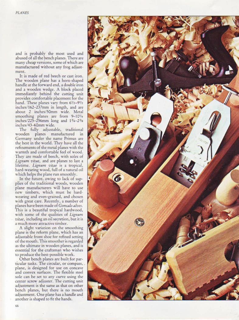
PLANES
and is probably the mosr used and abused of all the bench planes. There are many cheap versions, some of which are manufactured without any frog adjustment.
It is made of red beech or cast iron. The wooden plane has a horn-shaped handle at the forward end, a double iron and a wooden wedge. A block placed immediately behind the cutting unit provides comfortable placement for the hand. These planes vary from 6lf2-91f2 inches/162-237mm in length, and are about 2 inches/SOmm wide. Metal smoothing planes arc from 9-10lf4 inches/22S-256rnrn long and 13/4-2% inches/43--60mm wide.
The fully adjustable, traditional wooden planes manufactured in Germany under the name Primus are the best in the world. They have aU the refinements of the metal planes with the warmth and comfortable feel of wood. They are made of beech, with soles of Lignum vitae, and are planes to last a lifetime. Lignum vitae is a tropical, hard-wearing wood, full of a natural oil which helps the plane run smootl1ly.
In the future, owing ro lack of supplies of the traditional woods, wooden plane manufacturers will have to use new timbers, which must be hardwearing and even-grained, and chosen with great care. Recently, a number of planes have been made of Goncalo alves. This is a beautiful tropical hardwood, with some of the qualities of Lignum vitae, including an oil secretion, but it is a much more attractive timber.
A slight variation on the smoothing plane is the reform plane, which has an adjustable front shoe for refined setting of the mouth. This smoother is regard~d as the ultimate in wooden planes, and is essential for the craftsman who wishes tO produce the best-possible work.
Other bench planes are built for particular tasks. The circular, or compass, plane, is designed for use on concave and convex surfaces. The Aexible steel sole can be set tO any curve using rhe cemer screw adjuster. The cutting unit adjustment is the same as that on other bench planes, but there is no mouth adjustment. One plane has a handle and another is shaped to fit the hands. ·
66

PLANES
Opposite: 1 The replacement-blade plane IS a recent development; the model is supplied w1th s1x throw-away blades and has a Teflon-coated sole. 2-5 A select1on of wooden planes with spnng-loaded cutter adju.stment and Ugnum wtae soles. 2 9-mch/225-mm reform-type smoothing plane with adjustable front shoe. 3 25~-inch/64 .1-mm try1ng plane. 4 91-7-inch/ 237 -mm jack plane. 5 11-inch/275-mm rebate or rabbet plane w1th an adjustable front shoe Above, a f1ne-quahty 87 a-lnch/221-mm reformtype smoothing plane With a pearwood body. Ugnum v1tae sole, spnng-loaded cutter adjustment, and an adjustable front shoe. Left, the compass plane has a thin, flexible steel sole for planing concave and convex shapes. The sole IS located at the heel and toe of the body and a screw adjustment ra1ses or lowers the center.
67

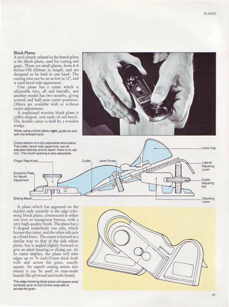
Block Planes A tool closely related to the bench plane is the block plane, used for cutting end ~rain. These are small planes, from 6-8 mchc~/15~200mm in length, and are desi~ned to be held in one hand. The cuttmg iron can be ~etas low as 12°, and IS used bevel-side uppermost.
One plane has a cutter which is adjustable fore, aft and laterally, and another model has rwo mouths, giving normal and bull nose cutter positiom. Others are available with or without cutter adjustment.
A traditional wooden block plane is coffin-shaped, and made of red beech. The double cutter is held by a wooden wedge. When using a block plane, right, guide the sole w1th the forward hand.
Cross-section of a fully adJUStable blod< plane. The cutter, bevel-stde uppermost, can be adjusted laterally and for depth; there is no cap 1ron. The mouth opening is also adjustable.
F1nger Rest Knob -----,
Eccentnc Plate tor Mouth AdJUStment
Shdmg Mouth ____ _,
A plane which has appeared on the market only recently is the edge trimming block plane, constructed in either cast iron or manganese bronze, with a very high-quality finish. The plane has a V-~haped underbody one side, which houses the curter, and the other side acts as a fixed fence. The cutter is housed in a similar way to that of the side rebate plane, but is angled slightly forward to ~ive an ideal shearing or slicing cut. As tts name implies, the plane will trim edges up to 'l's i nch/21 mm thick both with and across the grain, exacdy square. ItS superb cutting action also means it can be used on man-made boards like plywood and multi-board.
The edge trimming block plane will square wood surfaces up to 'l'a inoh/21 mm wide with or across the grain.
Cutter Lever Screw
PLANES
.....,... ___ Lateral AdjUSting Lever
69

Rebate and Fillister, Plough and Multi-purpose Planes The bench rebate, or rabbet, plane is a bench jack plane with a blade modified for cutting rebates. \\'ith metal bench rebate planes, the blade extends the full width of the sole, whereas wooden bench rebate planes have an angled blade breaking through the body on one side.
Purpose-built rebate, rabbet, or fillister planes are also available with metal or wooden bodies. The metal rebate plane is particularly useful for the craftsman working constantly on rebates and fillisters up w 1112 inches 37mm wide. It is made of cast iron, with two fence arms and two positions for the cutter- the normal position, where it is fully adjustable, and the bull nose position, where it has to be adjusted by hand before the lever cap is tightened.
The plane is fitted with a steel spur which severs the top fibers before the blade when cutting across the grain. The fence can be set across the cuuer to limit its width, or it can be transferred to the left-hand side. Sometime~. thi~ plane is called a moving fillisrer. \Vith the fence removed, it can be used as a simple
A wooden rebate plane wrth adJuStable cutter.
square plane. One version ]las a single fence ann and a lever-type curter adjuster.
Wooden rebate planes are made of beech, with a wedged cutter and steel striking knob, which is the only departure from the traditional style. Pnmus make a particularly good rebate plane, wirh a fully adjustable cutter. To tmprove cutting, the plane is fitted with an adjustable front shoe which allows the mouth to be set accurately. It is made of white beech, with a sole of L1gnum vitae. Improved handling is
70
1 A wooden hand router, used tor cutttng grooves and dados. 2 A n1neteenth-century style plough plane w1th an adjustable fence; the plough plane is des1gned pnmanly to cut grooves, but will also cut rebates. 3 A tongue and groove plane set; the tonguing plane cuts a tongue which f1ts tightly 1n the matched flatbottom groove cut by the groove plane. 4 A traditional wooden rebate plane.

PLA'\'£S
lett, the bench rebate plane is similar 1n destgn to other bench planes except that the blade extends across the full width of the sole. There is no fence guide, so a piece of wood has to be attached to the workp1ece to act as a guide; th1s can be removed after the rebate is begun. Below, the rebate or ftlhster plane is purpose· bUilt for cutttng rebates 11 has an adjustable fence, a depth gauge, and a forward pos1t10n for the cutter for plantng up to a stopped rebate
71
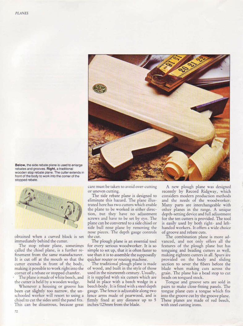
PLANES
Below, the side rebate plane is used to enlarge rebates and grooves. Right, a traditional wooden stop rebate plane. The cutter extends in front of the body to wotl< into the corner of the stopped rebate.
obtained when a curved block is set immediately behind the cutter.
The stop rebate plane, somerim~s called the chisel plane, is a further refinement from the same manufacturer. It is cut off at the mouth so that the cutter extends in front of th~ body, making it possible to work right imo the corner of a rebate or stopped chamfer.
The plane is made of white beech, and rhe cutter is held by a wooden wedge.
Whenever a housing or groove has been cut slightly too narrow, the unschooled worker will resort to using a chisel to cut the sides until the panel fits. This can be disastrous, because great
72
•
care must be taken to avoid over-cutting or uneven cutting.
The side rebate plane is designed to eliminate this hazard. The plane illustrated here has two cutters which enable the plane to be worked in either direction, but they have no adjustment screws and have to be set by eye. The plane can be converted to a side chisel or side bull nose plane by removing the nose pieces. The depth gauge controls the cut.
The plough plane is an essential tool for every serious woodworker. It is so simple to set up, that it is often faster tO
use than it is to assemble the supposedly quicker router or routing machine.
The traditional plough plane is made of wood, and built in the style of those used in the nineteenth century. Usually, it is supplied with six cutters which arc held in place with a beech wedge in a beech body. It is fitted with a steel depth gauge. The fence is adjustable along two fence arms made of pearwood, and is finnly fixed at any distance up to 5 inches/ 125mm from the blade.
A new plough plane was designed recently by Record Ridgway , which considers modem rroduction methods and the needs o the woodworker. Many parts are interchangeable with other planes in the range. A uniq\.1e depth-setting device and full adjustment for the ten curters is provided. The tool is easily used by both right- and lefthanded workers. It offers a wide choice of groove and rebate cuts.
The combination plane is more advanced, and not only offers all the features of the plough plane but has tonguing and beading cutters as well, maKing eighteen cutters in all. Spurs are provided on the body and sliding section to sever the fibers before the blade when making cuts across the grain. The plane has a bead stop to cut beads on tongued srock .
Tongue and groove sets arc sold in pairs to make dose-fitting panels. The mngue plane cuts a tongue which fits inro the groove cut by the groove plane. These planes are made of red beech, with steel cutting irons.

Right, cutting a rebate w1th a plough plane. The cutter f1tted is wider than the rebate required and the width of the rebate is set by the distance between the fence and the outside edge of the cutter. A more sophisticated version of the plough plane is the combination plane, below, designed to perform a Wide vanety of planing operatiOns. Below top right, cuttmg edge beading Below bottom right, cuttmg square and round mold1ngs
PLA,\ES
73

PLAN£S
7+
The multi-plane is made only by Record Ridgway. It is an expensive bur very versatile plane, which must have a place in all reference books, if not in the average workshop. It carries out all the work covered by the plough and combination planes previously mentioned,
The multi-plane will perform a wide range of cuts, above. Special cutters, left, are available m addition to the standard 24. and the special bases •llustrated below will cut hollows, rounds and stair nosings.
and a large number of additional cutters and bases are available to extend its use further. This plane is capable of ploughing, rebating, housing, tonguing, fiJlistering, beading, sash molding and slitting. Spurs help when cutting across the grain, and these can be housed when not in use. Long and short fence arms are supplied, which can be fined in two positions in the fence.
There is a fully adjustable depth gauge in the sliding section . Three pronged spurs which cut across the grain are housed in the body and sliding section. In addition, the plane has a bead srop, cam steady and a slitting cutter, which has an adjustable stop.
Special bases are available to cur hollows and rounds of various sizes. Stair nosings can also be cut. These bases slide over rhe fence arms, replacing the sliding section.

The Multi-Plane The multi-plane is made of nickel-plated steel and rosewood. Its components include an adjustable fence and depth gauge, two sets of fence arms (long and short), a beadmg stop, slltt1ng cutter, shdtng section. depth gauge, cam steady, and spurs for cross grain work. Except for the two smallest, all the cutters are fully adjustable
Cutter
Depth Gauge Adjusting Screw------:-oo~·
Skates
PLANES
_ ____ Fence Fine Setting Screw
Hardwood Fence
75
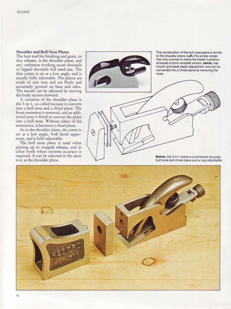
PLANES
Shoulder and Bull Nose Planes The best tool for finishing end grain, or riny rebates, is the shoulder plane, and any craftsman working secret dovetails or lapped dovetails will need one. The thin cutter is set at a low angle, and is usually fully adjustable. The planes are made of cast iron and are finely and accurately ground on base and sides. The mouth can be adjusted by moving the body section forward.
A variation of the shoulder plane is the 3-in-1, so-called because it converts into a bull nose and a chisel plane. The front extension is removed, and an additional nose is fitted to convert the plotne into a bull nose. Without either of the extensions, it becomes a chisel plane.
As in the shoulder plane, the cutter is set at a low angle, with bevel uppermost, and is fully adjustable.
The bull nose plane is used when planing up to stopped rebates, and in other work where extreme accuracy is required. It can be adjusted in the same way as the shoulder plane.
76
The construction of the bull nose plane is similar to the shoulder plane. left, this simple model has only a screw to clamp the blade in posttlon, whereas a more versatile version, below, has mouth and blade depth adjustment, and can be converted into a chtsel plane by removing the nose.
Below, the 3·10·1 plane is a combined shoulder. bull nose and chtsel plane and is fully adjustable
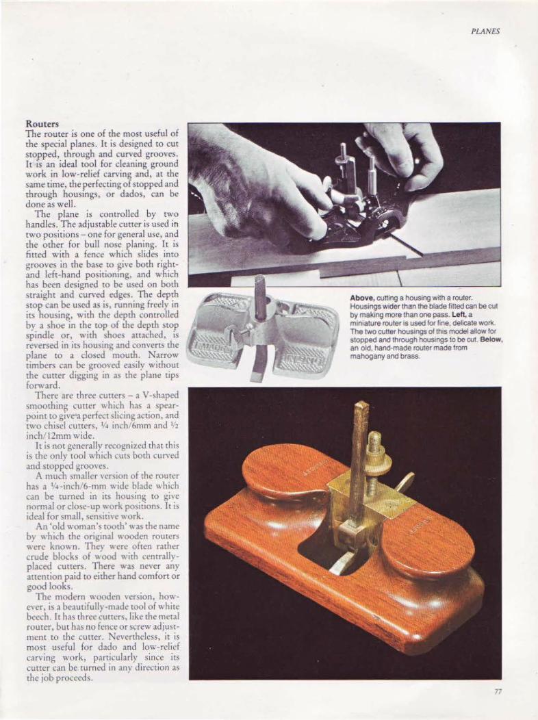
Routers The router is one of the most useful of the special planes. It is designed to cut stopped, through and curved grooves. It IS an ideal tool for cleaning ground work in low-relief caning and, at the same time, the perfecting of stopped and through housings, or dados, can be done as well.
The plane is controlled by two handles. The adjustable curter is used in two positions- one for general usc, and the other for bull no-,c planing. It is fitted with a fence which slides into grooves in the ba~e to give both rightand left-hand positioning, and which has been designed to be used on both straight and curved edg~. The depth stop can be used as is, running freely in it) housing, with thc Jcpth controlled by a shoe in the top of the depth MOp spindle or, \\ ith )hoes attached, is rc .. ersed in its housm~ and converts the plane to a closed mouth. Narrow timbers can be grooved easily without the cutter Jigging tn a'> the plane nps forward.
There arc three cutters - a v-.. haped smoothmg cuner which has ,1 spearpoint to give "a perfect ~l1cing ,1ction, and two chisel cutters, 1!4 inch16mm and 1, 2
inch/ 12mm wide. Tt i-; not generally reco~nizcd that this
is the only tool which cut\ both curved and stopped grooves.
A much smaller H'r,ion of tlw router has a 1 ~-inch /6-rnrn wide blade which can be rurncd in its hou'>ing to gi,·e normal or close-up work positions. It is ideal for small, scn~itivc '' ork.
An 'old woman's tooth''' as the name by which the original wooden routas were knO\\ n. The,· were often rather crude block.. of " .ood with ccntrallvplaced cutters. There was never any attention paid to either hand comfort or good looks.
The modern wooden version, howcH~r. i~ a beautifulh -made tOol of white bccl.':h. lllw; th rcc ~utter~. like the metal router, but has no fence or ~crew adjmtrnent tO the cutter. Nevertheless, it is most useful for dado and low-relief carving work, particularly since its cutter can be turned 10 ,1ny direction as the job pr(lcccds.
PLANES
Above, cutt1ng a housing with a router. Houssngs wider than the blade f1tted can be cut by mak1ng more than one pass. Left, a m1niature router tS used 101" line, delicate work The two cutter hous1ngs of th1s model allow lor stopped and through hous1ngs to be cut. Below, an old, hand-made router made from mahogany and brass.
77

PLANES
Planes for Special Trades In any major discussion on planes, those used by craftsmen making musical instruments must be included. This is usuaJiy excremel; delicate work, and the removal of the thinnest shaving in a very small area is often all chat is needed.
In the past, violin-makers made small planes to suit their particular needs, and had the blades fashioned by the local blacksmith. Many of the recognized manufacturers began to make these small planes in beech and boxwood.
The modern solution to this problem is the finger plane. Usually, this is made of brass, to a \'Cry high specification. The curter is set manually and held in place by either a rosewood or ebony wedge and a steel cros~pin. The soles are either flat or convex, and the body ~hape
711
varies according to the manufacturer. One range is cast in the shape of whales. However, the bodies are always 1-3 inches/25-7Smm long, and the blades are up to 'l's inch/2lmm wide. One brand has a toothing blade for veneer work.
These planes are designed to be held in one hand, with the forefinger resting on the front of the tool and the other fingers wrapped around it.
Not only are these beautifully-made planes essential for the violin-maker, but they are also useful for the skilled craftsman.
A small number of miniature planes arc available, made of exotic timbers. They do not conform to the strict specifications demanded by the present-day ,·iolin-makcr, but they arc well-made
and certainly will meet the needs of the model-maker.
Another one"-handed tool is the palm [>lane. This plane has a wooden handle fitted at the end of a steel rod, and looks particularly difficult to hold. However, tf the body is grasped between the thumb and fingers, the handle fits perfectly into the palm of the hand. Thts tool is easily controlled and the sensitive work it produces will be appreciated by wood craftsmen of all kinds, but particularly the model- and instrument maker.
An earlier -.ersion of the palm plane looked like a miniature block plane, \vith an extended rear handle. [r had curved and flat soles. A flat-soled plane imilar to this is available now, with or
without a handle.
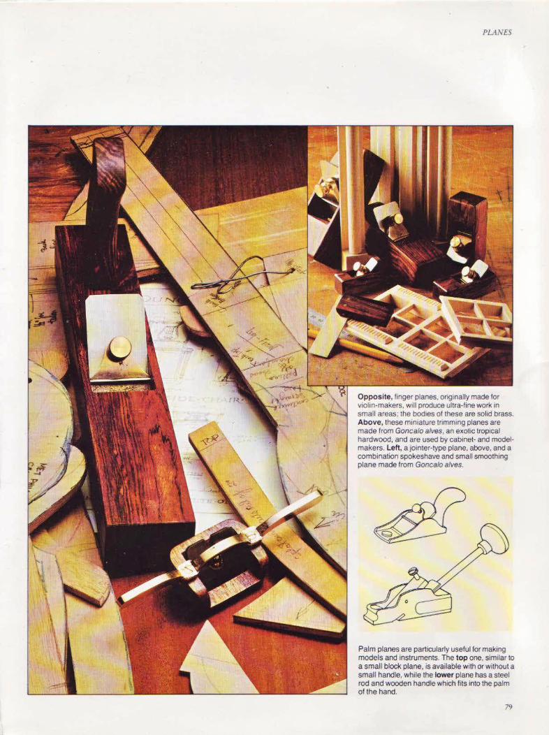
PLANES
Opposite, finger planes, orig~nally made for violin-makers. Will produce ultra-fine work 1n small areas: the bodies of these are solid brass. Above, these mimature trimming planes are made from Goncalo alves, an exotic tropical hardwood, and are used by cabinet- and modelmakers. Left, a jointer-type plane, above, and a combination spokeshave and small smoothing plane made from Goncalo alves.
Palm planes are particularly useful for making models and instruments. The top one, similar to a small block plane, is available with or without a small handle, while the lower plane has a steel rod and wooden handle which fits into the palm of the hand.
79

PLANES
llO
Spokeshaves There are many jobs which cannot be tackled with a plane because of size, accessibility or peculiarity of design, but they can be done. with a spokeshave.
This is really a small plane, with handles set on both sides for control. The cutter is set in the same way as with the plane, but it has no cap iron. There are flat-faced spokeshaves for convex surfaces and round-faced ones for curves.
Usually, the metal spokeshave body is constructed of malle:tble iron to reduce the chance of breakage.
Combination spokeshaves have one flat and one round sole and do not cost much more than a single spokeshave, but they are not as easy to-handle.
A useful addition to the spokeshave range is one with an adjustable mouth.
Before buying, it is advisable ro hold the spokeshave in order to judge its possible performance - the handles should fit comfortably into the palms with the forefinger at the front, alongside the mouth. Good spokeshaving is largely a matter of correct wristwork, with the front of the tool pres$ed down with the fingers.
Draw knives The drawknife was the fo'rerunner of the spokeshave but, unlike this tool, it is drawn towards the worker, has no sole and therefore requires greater skill in use. This was and still is the tool of the wheelwright, bur it is suitable for a variety of other uses.
Drawknives can be used by the wood-can·er and sculptor for roughing down, and the cabinetmaker and the
The drawknife, above, 1soneof the Simplest shaping tools and can be used on large pieces of timber. A variation is the inshave, left, designed for hollowing out. A metal spokeshave, top lett, with blade adjustment screws. Always work with the gratn and keep edges square.
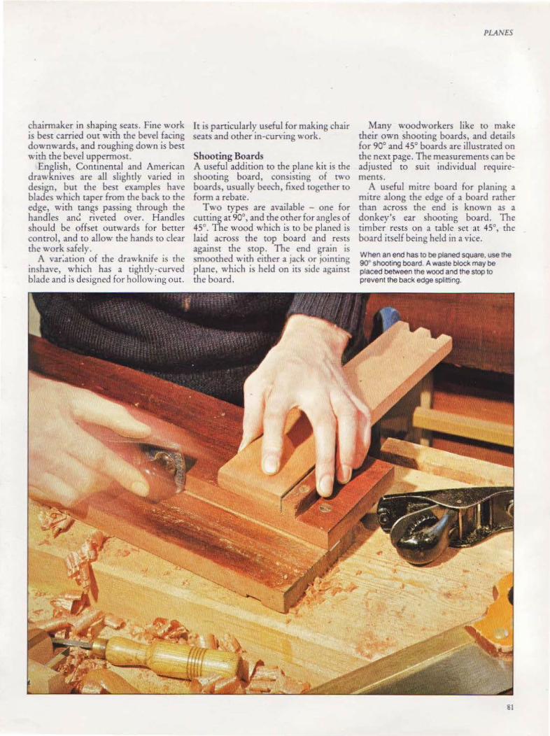
chairmaker in shaping seats. Fine work is best carried out with the bevel facing downwards, and roughing down is best with the bevel uppermost.
English, Continental and American drawknives arc all slightly varied in design, but the best examples have blades which taper from the back to the edge, with tangs passing through the handles anc! riveted over. H andles should be offset outwards for better control, and to allow the hands to clear the work safely.
A var:ation of the dra\\ knife is the inshave, which has a tightly-curved blade and is designed for hollowing out.
It is particularly useful for making chair seats and other in-curving work.
Shooting Boards A usefu l addition to the plane kit is the shooting board, consisting of two boards, usually beech, fixed together to form a rebate.
Two types are available - one for cutting at 90°, and the other for angles of 45°. The wood which is to be planed is laid across the top board and rests against the stop. The end grain is momhed with either a jack or jointing
plane, which is held on its side against the board .
Many woodworkers like to make their own shooting boards, and detaiJs for 90° and 45° boards are illustrated on the next page. The measurements can be adjusted to suit individual requirements.
A useful mitre board for planing a mitre along the edge of a board rather than across the end is known as a donkey's ear shooting board. The timber rests on a table set at 45°, the board itself being held in a vice.
When an end has to be planed square. use the 90" shooting board A waste block may be placed between the wood and the stop to prevent the back edge sphtting.
Sl

PLANES
Making a Shooting Board
A shooting board is easily constructed from two lengths of hardwood. A chamfer is cut along the bottom edge of the upper board to clear shavings. A wedge-shaped stop Is fatted an a housing in the upper board, but ensure that the edge against which the work rests rs square w1th the board. Candlewax rubbed onto the lower board wrlllet the plane slide smoothly.
82
Mrtres can be planed by erther mod1ly1ng the standard board by placang a 45• wedge against the stop or, better, by making a purpose-built mitre shooting board. The stop rs placed in the middle of the upper board with its edges cut at 45•; this enables both sides of the stop to be used.
If the mitre to be cut is across the thickness of the work, as with the sides of a box, a shooting board known as a donkey's ear can be made. The upper board slopes at an angle of 45• and a rectangular stop IS placed an the middle. The board IS held In a vice.
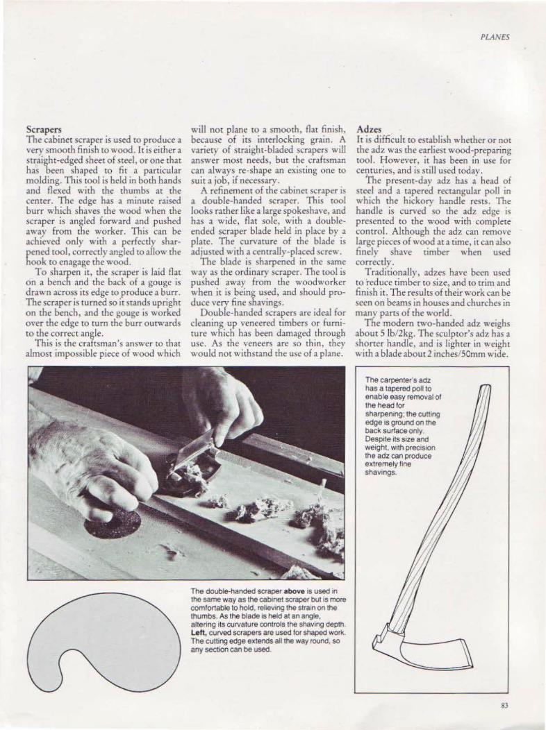
Scrapers The cabinet scraper is used to produce a very smooth finish to wood. It is either a straight-edged sheet of steel, or one that has been shaped to fit a particular molding. This tool is held in both hands and flexed with the thumbs at the center. The edge has a minute raised burr which shaves the wood when the scraper is angled forward and pushed away from the worker. This can be achieved only with a perfectly sharpened tool, correctly angled to allow the hook tO enagage the wood.
To sharpen it, the scraper is laid flat on a bench and the back of a gouge is drawn across its edge ro produce a burr. The scraper is turned so it stands upright on the bench, and the gouge is worked over rhe edge to turn the burr outwards to the correct angle.
This is the craftsman's answer to that almost impossible piece of wood which
"'·ill not plane to a smooth, flat finish, because of its interlocking grain. A variety of straight-bladed scrapers will answer most needs, but the craftsman can always re-shape an existing one to suit a job, if necessary.
A refinement of the cabinet scraper is a double-handed scraper. This tool looks rather like a large spokeshave, and has a wide, flat sole, with a doubleended scraper blade held in place by a plate. The curvature of the blade is adjusted with a centrally-placed ~ere".
The blade is sharpened in the same way as the ordinary scraper. The roo! is pushed away from the woodworker when it is being used, and should produce very fine shavings.
Double-handed scrapers arc ideal for cleaning up veneered timbers or furniture which has been damaged through usc. As the veneers are so thin, they would not withstand the usc of a plane.
The double-handed scraper above is used in the same way as the cabinet scraper but is more comfortable to hold, rehev111g the stratn on the thumbs. As the blade tS held at an angle, altering its curvature controls the shaving depth. Left, curved scrapers are used for shaped work. The cutting edge extends all the way round, so any section can be used.
PLAl\'ES
Ad zes It is difficult to establish whether or not the adz was the earliest wood-preparing tool. However, it has been in use for centuries, and is stiiJ used today,
The present-day adz has a head of steel and a tapered rectangular poll in \\ hich the hickorv handle rests. The handle is curved ' so the adz edge is presented to the wood with complete control. Although the adz can remove large pieces of wood at a time, it can also finely shave timber when used correctly.
Traditionally, adzes have been u~ed tO reduce timber to size, and to trim and finish it. The results of their work can be seen on beams in houses and churches in many parts of the world.
The modern two-handed adz weighs about 5lb/2kg. The sculpror's adz has a shorter handle, and is lighter in weight with a blade about 2 inches/ SOmm wide.
The carpenter's adz has a tapered poll to enable easy removal of the head for sharpening; the cutttng edge is ground on the back surface only. Despite its size and Weight, with preCISIOn the adz can produce extremely ftne shavtngs.
83
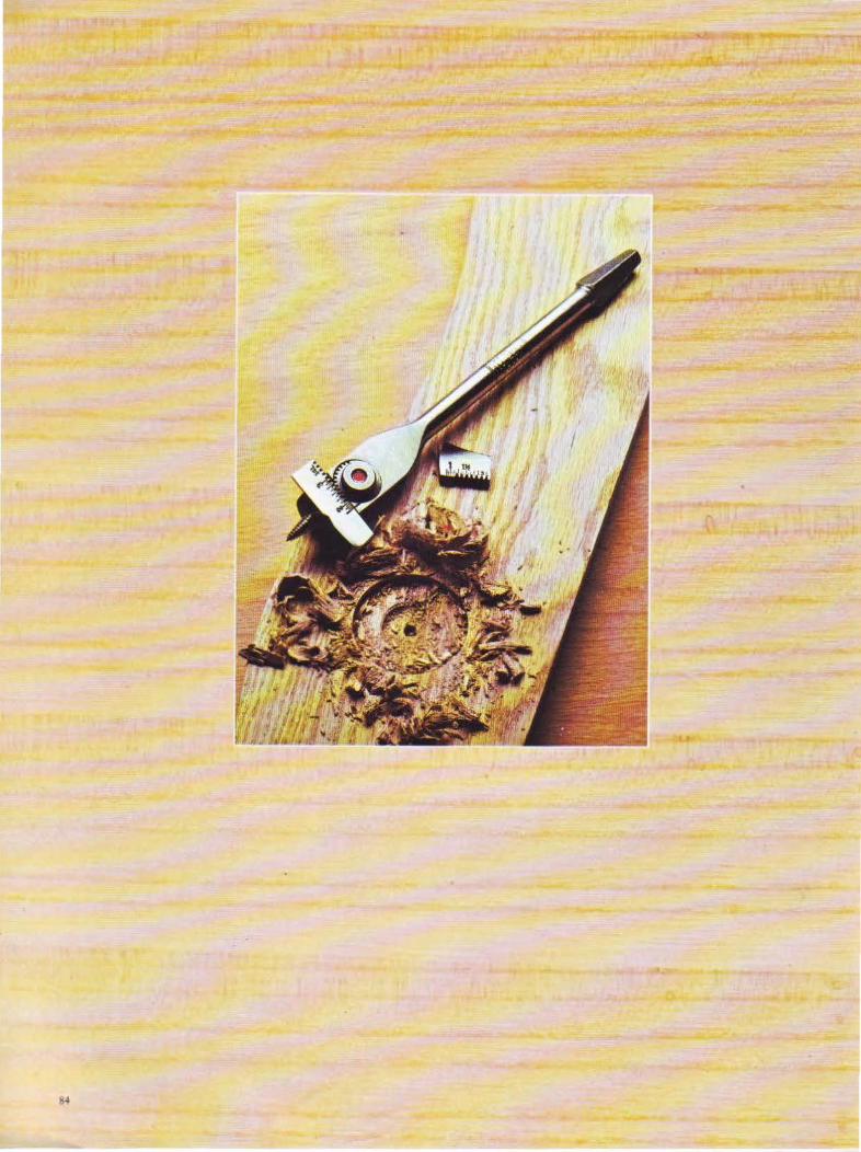

CHAPTERS/X
Boring Tools
Hales are usually bored either to house scre'l.{)s, bolts, nails or
dowels, or to serve as a decoration feature in a piece of
furniture.
85
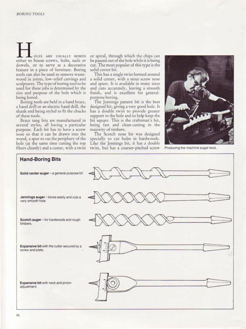
BORING TOOLS
H om AR£ usuALLY aoREO either to house screws, bolts, nails or dowels, or to serve as a decorati,·e feature in a piece of furniture. Boring tools can also be used to remove wa~tc" 'ood in joints, low-relief carvings and sculptures. The rvpc of boring tool to be used for these jobs is determined by the ~ize and purpose of the hole which is being bored.
Boring tools are held in a hand brace, a hand drill or an electric hand drill, the shank end being styled to fit the chuckc; of the~e tools.
Brace tang bits are manufactured tn
se\'eral styles, all ha,·ing a particular purpose. Each bit has ro have a screv. no e so that it can be drawn into the wood. a spur tO cut the periphery of the hole (at the same time cutting the cop fibers cleanly) and a cutter, with a rwist
!!6
Hand-Boring Bits
Solid center auger - a general-purpose btl
Jennings auger- bores easily and cuts a very smooth hole.
Scotch auger - for hardwoods and rough limbers.
Expansive bit with the cutter secured by a screw and plate.
Expansive bi t w1th neck and p1n1on adjustment.
or spiral, through which the chips can be passed out of the hole while it is being cut. The most popular of this type is the solid center bit.
This has a single twist fom1ed around a solid center, with a c;rout screv. nose and spurs. It i~ avaiiJble in many sizes and curs accurately, leaving a smooth finish, and is excellent for generalpurpose boring.
The Jennings pattern bit is the best designed bit, giving a very good hole. It has a double twist to provide greater support in the hole and to help keep the bit square. This i~ the craftsman's bit, being fast and dean-cutting in the majority of timbers.
The Scotch nose bit was designed specially to cut holes in hardwoods. Like the Jenning bit, it has a double twist, but ha~ a coarser-pitched screw Producing the mach1ne auger twist.
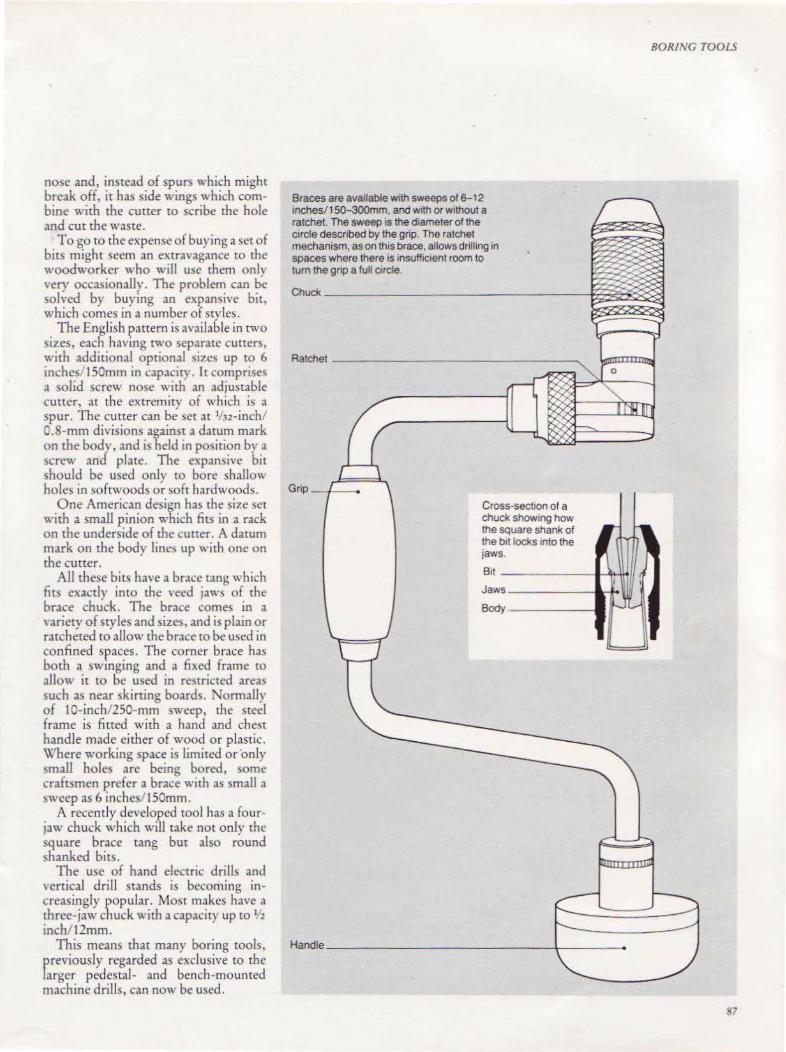
nose and, instead of spurs which might break off, it has side wings which combine with the cutter to scribe the hole and cut the waste.
To go to the expense of buying a set of bits might seem an extravagance to the woodworker who will usc them only very occasionally. The problem can be solved by buying an expansive bit, which comes in a number of styles.
The English pattern is available in two sizes, each having two separate cutters, with additional optional si1es up to 6 inches lSOmm in capacit) . It comprise<; a solid screw nose with an adjustable cutter, at the extremity of which is a spur. The cutter can be set at 1/32-inch/ 0.8-mm divisions against a datum mark on the body, and is held in position by a screw and plate. The expan~i\·e bit should be used only to bore shallow holes in softwoods or soft hardwoods.
One American design has the size set with a small pinion which fits in a rack on the underside of the cutter. A datum mark on the body lines up with one on the cutter.
All these bits have a brace tang which fits exactly into the veed jaws of the brace chuck. The brace comes in a \'ariety of styles and sizes, and is plain or ratcheted to allow the brace to be used in confined spaces. The corner brace has both a swinging and a fixed frame to allow ic co be used in re tric.:ted area~ such as near skirting boards. Normally of 10-inch/250-rnm sweep, the steel frame is fitted with a hand and chest handle made either of wood or plastic. Where working space is limited or ·only \mall holes are being bored, some craftsmen prefer a brace with as small a sweep as 6 inchcs/ lSOmm.
A recently developed tool has a fourjaw chuck which will take not only the square brace tang but also round shanked bits.
The use of hand electric drills and vertical drill stands is becoming increasingly popular. Most makes have a three-jaw chuck with a capacity up to 1h inch. 12mm.
This means that many boring tools, previously regarded as exclusive to the larger pedestal- and bench-mounted machine drills, can now be used.
Braces are available with sweeps of 6-12 lnches/1 50-300mm, and w1th or Without a ratchet. The sweep 1s the diameter of the c~rcle described by the grip. The ratchet mechanism, as on this brace, allows drilling in spaces where there IS insUffiCient room to turn the gnp a full c~rcle.
BORING TOOLS
Chuck-------------~~~~;g
Cross·sectton of a chuck showing how the square shank of the brt locks 1nto the jaws.
Bit - ------+-+iti/1 Jaws-------~~
~--------~- ~~
87
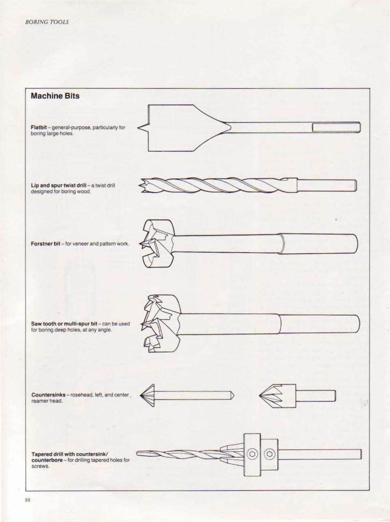
BORING TOOLS
Machine Bits
Flatbit - general-purpose, parttcularty tor bonng large holes.
lip and spur twist drill - a twtst drill designed for boring wood.
Forstner bit - for veneer and pattern work.
Saw tooth or multi-spur bit - can be used tor boring deep holes, at any angle.
Countersinks - rosehead, lett, and center reamer head.
Tapered drill with countersink/ counterbore - tor drilhng tapered holes for screws.
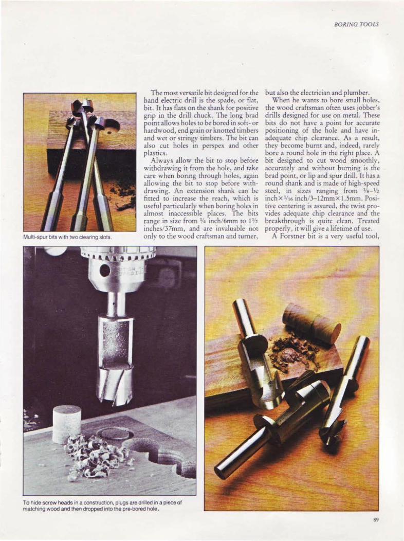
Multi·Spur bits w1th two cleanng slots.
The most versatile bit designed for the hand electric drill is the spade, or flat, bit. It has flats on the shank for positive grip in the drill chuck. The long brad point allows holes to be bored in soft- or hardwood, end grain or knotted timbers and wet or stringy timbers. The bit can also cut holes in perspcx and other plastics.
Always allow the bit to stop before withdrawing it from the hole, and take care when boring through holes, again allowing the bit to stop before withdrawing. An extension shank can be fitted to increase the reach, which is useful particularly when boring holes in almost inaccessible places. The bits range in size from 1 ~ inch/6mm to 11 2
inches/37mm, and are invaluable not only to the wood craftsman and turner,
To hide screw heads In a construction, plugs are drilled in a piece of match1ng wood and then dropped into the pre-bored hole.
BORiNG TOOLS
but also the electrician and plumber. When he wants to bore smaJI hob,
the wood craftsman often uses jobber's drills designed for use on metal. These bits do not have a point for accurate positioning of the hole and have inadequate chip clearance. As a result, they become burnt and, indeed, rarel} bore a round hole in the right place. A bit designed to cut wood smooth!}, accurately and without burning is the brad point, or lip and spur drill. lt has a round shank and is made of high-speed steel, in sizes ranging from 1 s-1
l
inch X 11t6 inch 3-11mmx I.Smm. Po~t rive centering is assured, the twist provides adequate chip clearance and the breakthrough is quite clean. Treated properly, it will give a lifetime of use.
A Forstner bit is a very useful tool,
89

BORING TOOLS
Doweling Jigs
The simplest method of aligning a doweling joint is to use a dowel locator, 1. Having first positioned the locator on one of the halves of the joint, the other half is aligned over it. By pressing down, a clear mark will be made on the timber; a collar prevents the locator being pushed all the way into one of the halves. Having marked the doweling joint, a doweling jig will be required to drill the dowel holes square and true in the two halves of the joint. Both the doweling jigs, below, have brushes which keep the drill bit vertical during drilling. The jig, 2, has five brushes from Y4- 1!2 inch/6-12mm and the fences open and close simultaneously, so the bit is automatically centered. With the jig 3, the bush is held by a clamp. After the jig is attached to the timber to be drilled, the position of the bush is then adjusted separately. Bushes range in size from •f,r-Vz inch/4.5-12mm.
90
Left and above, a more versatile doweling jig will both guide the drill bit and align the holes in both halves of the joint. There are two heads: one is a reference or fixed head, while the position of the other is adJUStable. Two bush carriers hold the drill bushes and adjustable side fences. When drtlling the end grain of one half of a doweling joint, left, the adjustable head is positioned just clear of the work and the jig is then held in place by one of the clamping screws. The side fences must be touching a side face of the work. To drill the side edge of the other half of the joint, the adjustable head is removed and the jig is inverted; it will then be perfectly aligned tor drilling the other half of the joint. When drilling boards longer than the slide rods, above, remove both the heads and press the side fences hard against the board. A dowel placed in the previously-drilled hole will ensure that the holes are evenly-spaced along the edge. Invert the jig to drill the holes in the other board.
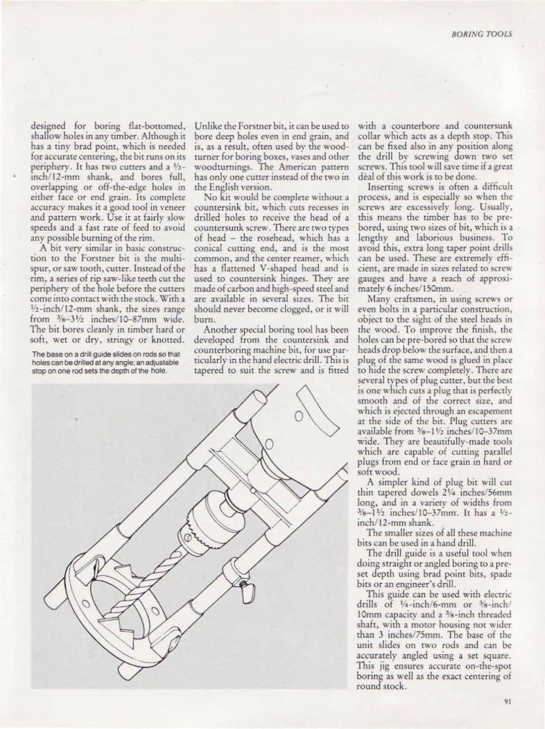
designed for boring flat-bottomed, shallow holes in any timber. Although it has a tiny brad point, which is needed for accurate centering, the bit runs on irs periphery. It has two cutters and a 1'zmch 12-mm shank, and bores fuJI, overlapping or off-the-edge holes in either face or end grain. Its complete accuracy makes it a good tool in veneer and pattern work. Use it at fairly slow speeds and a fast rate of feed tO avoid any possible burning of the rim.
A bit very similar in ba.)ic construction to the Forstner bit is the multispur, or saw tooth, cutter. Instead of the nm, a series of rip saw-like teeth cut the periphery of the bole before the cutters come into contact with the stock. With a 1'2-inch/ 12-mm shank, the sizes range from ·%-3 112 incbes/10-87mm wide. The bit bores cleanly in timber hard or soft, wet or dry, stringy or knotted.
The base on a dnll guide slides on rods so that holes can be drilled at any angle; an adjustable stop on one rod sets the depth of the hole.
Unlike the Forstner bit, it can be used to bore deep holes even in end grain, and is, as a result, often used by the woodturner for boring boxes, vases and other woodturnings. The American pattern has only one cutter instead of the two in the English version.
No kit would be complete without a countersink bit, which cuts recesses in drilled holes to receive the head of a countersunk screw. There are two types of head - the rosehead, which has a conical cutting end, and is the most common, and the center reamer, which has a flattened V -shaped head and is used to countersink hinges. They are made of carbon and high-speed steel and are available in several sizes. The bit should never become clogged, or it will burn.
Another special boring tool has been developed from the countersink and counterboring machine bit, for use particularly in the hand electric drill. This is tapered to suit the screw and is fitted
BORING TOOLS
with a counterbore and countersunk collar which actS as a depth stop. This can be fixed also in any position along the drill by screwing down two set screws. This tool will save time if a great deal of this work is co be done.
Inserting screws is often a difficult process, and is especially so when the screws arc excessively long. Usually, this means the timber has to be prebored, using two sizes of bit, which is a lengthy and laborious business. To avoid thi~, extra long taper poim drills can be used. These are extremely cffi cient, are made in sizes related to c;crcw gauges and have a reach of approximately 6 inches/150mm.
Many craftsmen, in using screws or even bolts in a particular construction, object to the sight of the steel heads in the wood. To improve the finish, the holes can be pre-bored so that the screw heads drop below the surface, and then a plug of the same wood is glued in place to hide the screw completely. There are several types of plug cutter, but the best is one wh1ch cuts a plug that is perfectly smooth and of the correct size, and which is ejected through an escapement at the side of the bit. Plug cutters arc available from ·%-1 1h inches/10-37mm wide. They are beautifully-made tools which are capable of cutting parallel plugs from end or face grain in hard or soft wood.
A simpler kind of plug bit will cut thin tapered dowels 2% inches/ 56mm long, and in a variety of widths from %-I V2 inchcsl l0-37mm. It has a 1 2 -
inch/ 12-mm shank. The smaller sizes of aU these machine
bits can be used in a hand drill. The drill guide is a useful tool when
doing straight or angled boring to a preset depth using brad point bits, spade bits or an engineer's drill.
This guide can be used with electric drills of '14 -inch/6-mm or 3/s-inch lOmm capacity and a 318-inch threaded shaft, with a motOr housing not wider than 3 inches/ 75mm. The base of rhc unit slides on two rods and can be accurately angled using a set square. This jig ensures accurate on-the-spot boring as welJ as the exact centering of round stock.
91
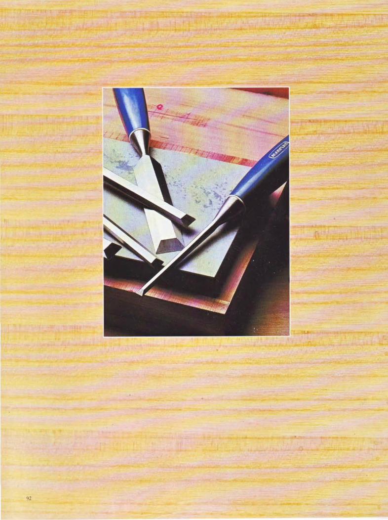

CHAPTER SEVEN
Chisels The chisel
is one of the most widely used and generally
abused tools currently made.
91

CHISELS
T. CHISEL IS ONE of the most widely-used and generally abused tools currently made. Although available in a wide variety of shapes and sizes, each designed for a different purpose, many woodworkers usc only one type of chisel fo r every job. However, many
modern manufacturers have rationalized their ranges to the extent that many special types of-chisels are hard to find, so often the woodworker has to make do with what is available.
The ch isel performs many functions and, depending on the job, is used in either the left or right hand . Often, the chisel is in use for long periods at a time, and may even be used with a mallet.
Bearing these factS in mind, the chisel must be selected not only for the quality of its steel and the manufacturer's assurance that it has been properly heattreated, but also for the excellence of its handle design. Too often in the past, chisel handles were made to suit the blade and shape of the woodturning machine, and not of the human hand. Many of these chisels were not only difficult to hold but, with prolonged use, made the hand sore and the arm ache. Fortunately, the present-day manufacturer has paid greater attention to ergonomics, and chisels are designed with not only the hand in mind but also the material used, so that it is comfortable to grip. Many of these handles are practically indestructible, and certainly, most are splitproof. The overall design and color has also been considered.
When looking for a chisel, the woodworker would be well advised to seek out those from a reputable manufacturer. Hold the chisel in both hands, check the handle for firmness and the blade for flatness. At the same time, notice the quality of the grinding, as a badly-ground chisel will require a great deal of work on the oilstone before the fine hairline cutting edge is produced. If a bevel edge chisel is being selected, make sure that the bevels are finely ground. Whilst extreme accuracy of size is not vital, usually if a mortice chisel is bought , it is best to check its accuracy.
Examine the chisel closely to check the alignment of the blade and th~ handle. Balance should not be ignored,
94
Chisel and Gouge Types Chisels can be divided into two types, depending on the way the blade is attached to the handle. The tang method is shown top right and the socket method bottom right.
Designed lor general wood-cutting, the firmer has parallel sides and tapers very slightly towards the cutting edge.
The beveled edge firmer chisel has now more or less replaced the firmer chisel.
The handle of the registered mortice chtsel has the normal ferrule, and a steel hoop at the striking end.
The hoop on this chisel prevents the handle splitting.
The wide side of the mortice chisel gives greater strength than the firmer. The handle is designed for use with a mallet.
The paring chisel has a D longer blade than the firmers and is used for tnmming long grooves.
The upturned cutting edge on the swan· necked or lock mortice chisel is for cutting out waste from deep recesses.
When there is no room for a conventional chisel a drawer lock chisel can be used.
Firmer gouges have blades of two types. The out-cannel, top right, has the cutting bevel ground on the outside, the in-cannel, bottom right, has it ground on the inside. The former is used for shapes such as hollowed-out finger pulls on drawers. Cuts made by the latter are straight but curved in section.
The firmer gouge illustrated here is of the in·cannel type.
The paring gouge is like the in-cannel firmer gouge I ( but lighter and longer It is also available with a cranked neck. This clears the hand from the stock [I and makes sure that the blade lies flat.
~-->=€~~ ~ D ~~ J
D ;::][ J
D 7=tC1 ID «! =::r:t: :J
):[L ~
w=- SJ
c;J ;I])
II =l "]
~ I ~
;?T _]

as a thick, heavy-bladed chisel will be out of balance and make working difficult. If the handle is wooden, check it for splits and other flaws. The quality of steel or the correctness of its heat treatment cannot be checked, so once again, emphasis must be laid on the selection of brand name tools which invariably carry a guarantee. A good chisel, correedy sharpened, will keep its edge for a long time, unless it is abused, so that valuable time is not wasted in resharpening fairly new chisels.
Chisels can be classified under three groups - general-purpose, mortice and special. The handles of all these chisels are secured either by a tang or socket, and are made from either wood or plasttc. The moSt popular wood amongst British craftsmen is Eu ropean 3
box, but ash and beech are also widely used, although one British manufacturer uses jarrah and another, rosewood.
The handles must be checked in the knowledge that they may be struck with a mallet and that often the chisel may be wrenched from side to side. Therefore, the wood must be close-grained and free from knots; and must not be prone to
surface cracking and splitting. A hard but pliable wood, which is shockresistant, is essential. Few of the available timbers have all these features-ash, for example, is fairly hard, pliant and knot-free, but its gram is quite open. Beech is closer-grained but not quite as pliant.
The early English edge-toolmakers chose boxwood, which is probably unequalled in its suitability. Boxwood (Buxw sempervirens) is indigenous to Europe and is regarded largely as a decorative shrub or tree for hedges and gardens. It has a narrow trunk and grows wildly in misshapen branches, reaching about 8 feet/ 2.4m high. The handles are turned from the branches .
.Box was used by the printer and engraver in the past, and it is likely that these blocks came from trees of some size . The blocks were cut with the grain running vertically, and sold by the cubic inch. Various substitutes for box have been tried, such as San Domingo boxwood and zapatero, but neither of them
CHISELS
The stages of cutting a mortice for a tenon with secret haunch are illustrated above and left: 1 The mortice gauge is set using the chisel itself rather than a ruler. as this is more accurate. 2 The wood is marked. 3-4 The chisel works along the projected mort1ce area. 5 The haunch is cut.
95
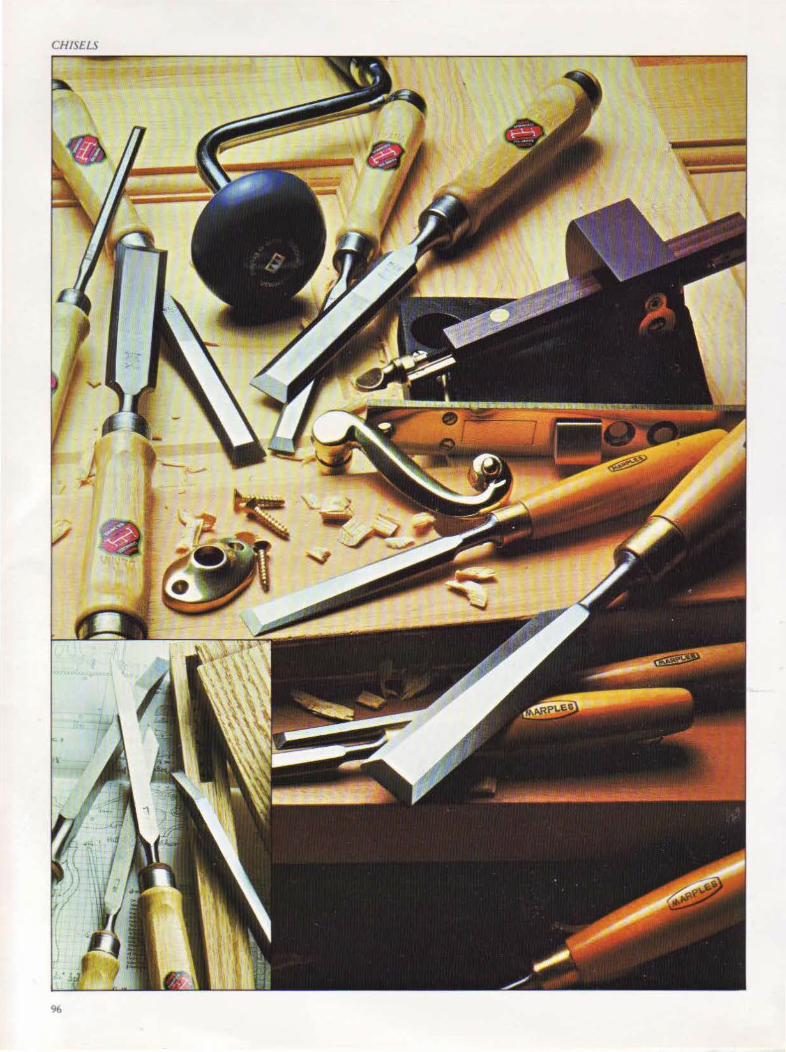
CHISELS
96
are equal to the European box. The timber is butter-yellow in color, although the smaller timbers have a grey streak running through them.
The splitproof plastics are cellulose acctah! butyrate, cellulose acetate and polypropylene.
Half a century ago, the most widely used chisel was the firmer. This has a thick steel blade with handles of box, beech, ash and plastic. It is a ·genera lpurpose tool, suitable for most jobs and, a~ it has a stout blade, can be driven '' ith a mallet if the handle i'i wooden, and" ith a hammer if it is plastic. However, the popularity of the firmer chisel has been superseded by that of the bevel edge, as it is virtually identical, and woodworkers arc reluctant to buy two chisels which perform the same tasks.
The bevel chisel was designed to cut dovetails- the long edges are beveled to cut the corners of the dovetails. When buying this chisel, the bevel must be checked for a fine edge, as some manufacturers produce chisels with a bevel edge that is far too thick.
All fine cutting can be carried out with the bevel chisel but it should not be used for deep cuning. Horizontal and vertical paring, chamfering both with and across the grain, dovetailing, housing, stopped housing and dovetailed housings across narrow boards are all well within the capacity of this chisel.
The cutting of mortices is a tough task for a chisel, but luckilv a chisel has been produced to combat this. The London pattern sash mortice chisel has a boxwood handle and a thickened blade which, together with a solid bolster, l,iives great strength. A leather washer httcd between the brass ferruk and the bolster shoulder absorbs shock. The blades have a reach of 6112 inches/ 162mm and are accurate to width, although it is advisable to set the mortice ~auge spurs to the chisel and ignore the mdicatcd si7e.
Illustrated top left on the facing page are heavyduty double-hooped chisels. The handles are ash, w1th steel hoops at both ends to prevent splitting. Bottom right are bevel edge chisels w1th boxwood handles. Inset: double-hooped morttce chtsels with ash handles and leather shock washers.
A variation on this chisel is one which has a purpose-designed plastic handle, and a nvlon washer. This handle is ideal for the'mortice chi!>cl. Its size suits the majority of hands, the four-square cross-sectional shape gi,·cs positive grip and helps ro counter any slipperiness experienced with the material. Also, it is curved to avoid blistering the hands.
Another chisel which can be used in monicing is the steel hooped chisel, known as the regi!>tered mortice chisel in Britain. This chisel i.'i of normal length, with a blade thicker than the firmer, but its special feature is a steel ferrule and steel hoop at the end of an ash handle.
A similar chisel has an oval handle, but the timber extends beyond the steel hoop, so that it can be driven with a mallet only.
A long, thin paring chisel is needed to cut housings (slots across the grain). The blade is thin and beveled on its long edges and has the required reach, as well as the clearance afforded by rhe bevel. Thil> chisel is the onl} one which can be used to cut a dovetailed hou)ing.
It is available with a cranked, or trowel, neck, which is an excellent feature as it clears the hand from the stock, and ensures the blade lies flat, particularly on very wide work. When selecting this type of chisel, it is vital to check that the chi!>d is Aat across both rhe width and length. Although slight up-turning of the blade is an advantage, the opposite would make Aar cutting impossible.
When paring vertically with a chisel or paring gouge, it is best to work on a cutting board to protect the bench top. One can be made easily from a piece of beech or other even-grained hardwood. 1f a strip of wood is screwed onto the underside of the board, it can be held in a vice when in use.
A popular chi!!el amongst some '~orkers is the butt, or pocket, chisel. With the exception of a shorter blade, this chisel is identical to the bevel edge chisel. It is very useful when cutting the housings for burt door hinges.
The swan-neck mortice chisel is used to hollow out the mortices for door locks and other deep recesses. It has a
CHISELS
beech handle and a long blade with an up-turned cutting edge, made of steel.
Another useful tool is the drawerlock chisel, which cuts lock recesses in drawers and other confined space!.. It has a square-sectioned steel bar with borh ends cranked at right-angles, and ground to a fine edge. Once in position, the chisel is struck with a hammer.
Gouges Gouges which are classified as in-cannel and out-cannel are incJuded in the special chisel group. Cannel is a word which does not appear in the English dictionary bur, nevertheless, is a term well-known in both the Sheffield chisel industry and in North America.
In-cannel means the cutting bevel has been ground on the inside, and outcannel means it has been ground on the outside. In- and out-cannel gouges are available as firmer and paring gouges, in a variety of blade sizes and curves. Incannel gouges w:th longer blades and cranked necks are also on the market. High-quality gouges have boxwood handles.
The striking of any chisel or gouge, other than the registered pattern or drawer-lock chisel, should be done with the joiner's mallet. This has a handle of pliant ash, the head is best made from Danish beech, and the handle socket is tapered to ensure a tight fie.
Knives Another edge tool which is vital in the workshop is the knife, because it is needed to mark out lines which have to be cut either with the saw or chisel. The woodworker can choose between knives with blades ground on one side only, or on both, and with wooden or plastic handles. Knives needed for other work are available in various shapes. The best-known craft knives were developed in Sweden many yean a~o when woodcraft was first taught in schools. They are known as Sloyd knives, come in a \'ariery of blade lengths and can be used for ~any workshop tasks as well as for whittling. Knives designed for whittling and chip carving will be discussed in detail in Chapter Ten on carving tools.
97

CHAPTER EIGHT
Abrasives Abrasive tools are
cutting tools with either sharp edges of steel or various grades of natural
or man-made grit
99
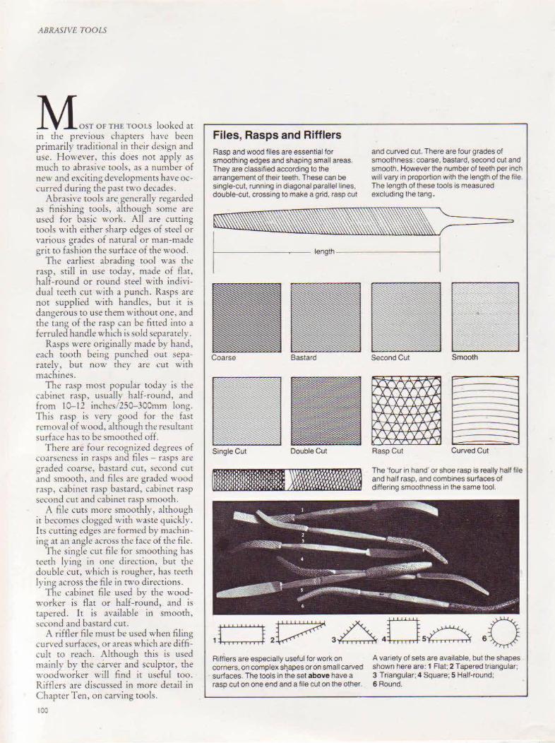
ABRASIVE TOOLS
M OST OF TH£TOOLS looked" in the previous chapters have been primarily traditional in their design and usc. However, this does not apply as much to abrasive tools, as a number of new :md exciting de,,elopments have occurred during the past two decades.
Abrasive tools are generally regarded as finishing wols, although some are used for basic work. All are cutting tools with either sharp edges of steel or various grades of natural or man-made grit to fashion the surface of the wood.
The earliest abrading wol was the ra~p. still in use today, made of flar, half-round or round steel with individual teeth cut with a punch. Rasps are not suppl ied with handles, but it is dangerous to use them without one, and the t.mg of the rasp can be fitted into a ferruled handle which is sold separately.
Rasps were originally made by hand, each tooth being punched out separately, but now they are cut with machines.
The rasp most popular today is the cabinet rasp, usually half-round, and from 10-12 inches 150-300mm long. This rasp is very good for the fast removal of wood, although rhe resulranr surface has to be smoothed off.
There ar~ four recogni?ed degrees of coarseness 111 rasps and files - rasps are ~raded coarsl!, bastard cut, second cut and ~rnooth, and files are gratkd wood rasp, cabinet rasp ba<;t,m!, cabinet ra:.p second cut and cabinet rasp smooth.
A file curs more smoothly, although it becomes clogged with waste quickly. Its cutting edges are formed by machinin~ ~tt an angle across the face of the file.
l'he single cur file for smoothing has teeth lying in one dirc<.'tion, but rhe double cut, which is rougher, has reeth lring across the file in rwo directions.
The cabinet file used by the woodworker is flat or half-round, and is tapered. lt is available in smooth, -;ccond and bastard cut.
A riffler file must be used when filing curved surfaces, or area~ which are difficult to reach. Although this is used mainly by the carver and sculptor, the woodworker will find it useful too. Rifflers are discussed in more detail in Chapter Ten, on carving tools.
100
Files, Rasps and Rifflers Rasp and wood files are essential for smoothing edges and shaping small areas. They are classrfied according to the arrangement of lherr teeth. These can be single-cut, runnrng in diagonal parallel lines. double-cut, crossing to make a gnd. rasp cut
and curved cut. There are four grades of smoothness: ooarse, bastard, second cut and smooth. However the number of teeth per inch wrll vary in proportion with the length of the ftle. The length of these tools rs measured excluding the tang.
~==~;;)
I ,.,,., I
Bastard
Single Cut Double Cut
Rifflers are especially useful for work on corners, on complex st"!apes or on small carved surfaces. The tools in the set above have a rasp cut on one end and a file cut on the other.
Second Cut
-----Rasp Cut Curved Cut
The 'four in hand· or shoe rasp is really half file and half rasp, and combrnes surfaces of differing smoothness in the same tool.
A variety of sets are available, but the shapes shown here are: 1 Flat; 2 Tapered triangular; 3 Triangular; 4 Square; 5 Half-round; 6 Round.

A 'en useful wol, )lmilar to the met.1lwo~ker's dreadnought file, is the A' en Filema!>tCr. It serYes rwo purposes. as the curved teeth on one side gi' e an almost plane-l[ke shaving, leaving a superb fini~h. and rhe crosstiled teeth on the apposite side can bl· U\cd to rough down. Jt is I 0 inche) 25Cmm long, and ~~available in both flat .tnJ half-round stYles.
The Sranlcv S~rform ha" become inLre.lsingly po.pular in recent ~-ears . Thi) unique tOol was patented by an English firm, 1-irrh Clcvcl.lnd. almost twenty 'l:ars ago and, although the wol fonm have _changed, the original blade design remams.
The blade is pierced to form rows of cutting edges, which leave a surface similar to that of the rasp. The volume of wood removed is considerable, and
ABRASI\ 1' TOOLS
The Aven Filemaster, top, has one surface of cross-filed teeth for rough work and one of curved teeth, whrch grves an extra-smooth frnrsh The Trimmatool, bottom, offers the specral facility of an adjustable curved blade for concave cuts. The curved teeth of these tools, left, are virtually self-clearing.
ICI
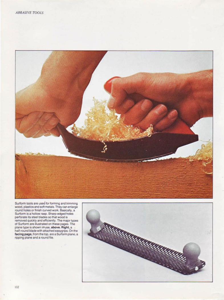
ABRASIVE TOOLS
Surform tools are used for forming and trimm1ng wood, plastics and soft metals. They can enlarge round holes or finish curved work. Basically, a Surform is a hollow rasp. Sharp-edged holes perforate its steel blades so that wood is removed quickly and effiCiently. The maJOr types of Surform are illustrated on these pages. The plane type is shown Ill use, above. Right, a half -round blade w1lh attached easygrips. On the facing page, from the top. are a Surform plane, a ripp1ng plane and a round file.
102
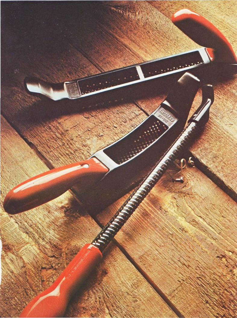
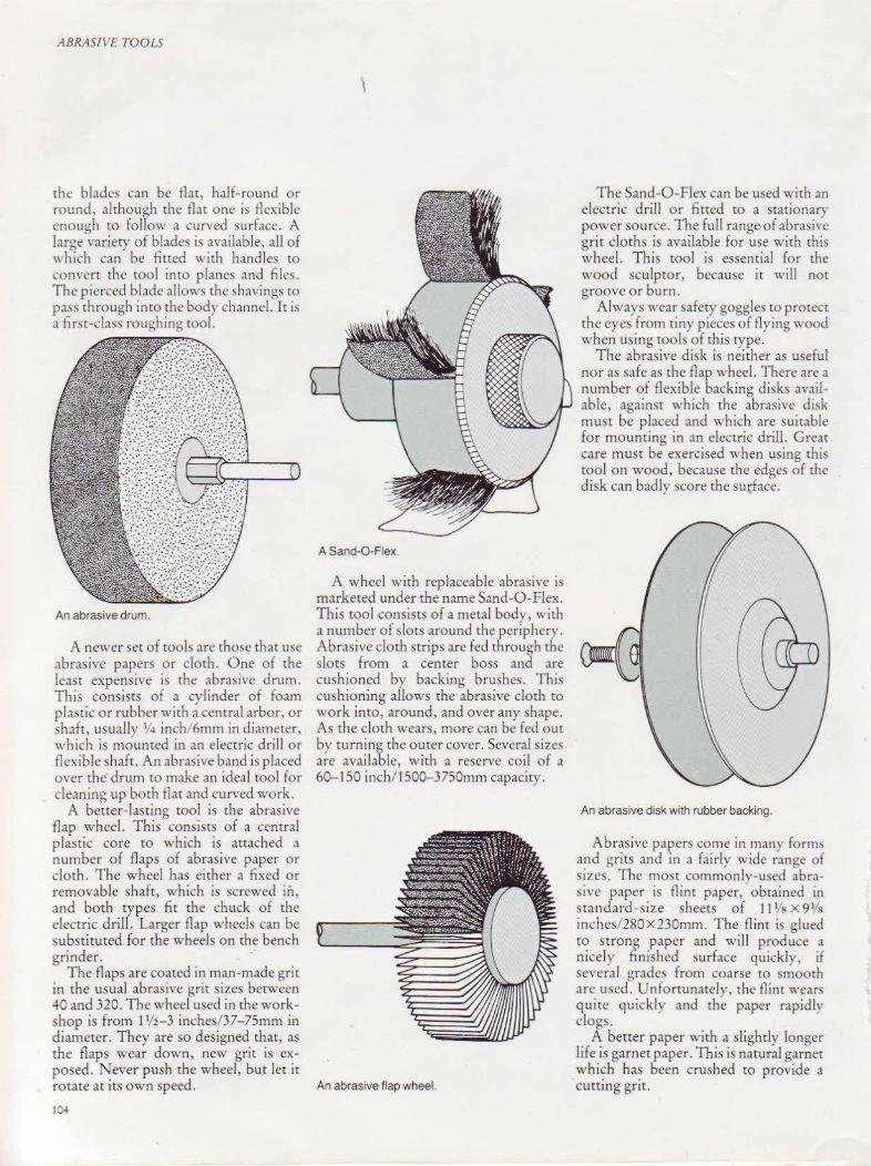
ABRASfVE TOOLS
the blades can be flat, half-round or round, although the flat one is flexible enough to follow a curved surface. A large variety of blades is available, all of which can be fitted with handles to com·crt the tool inro planes and files. The pierced blade allows the shavings to pass through into the body channel. Iris a first-class roughing tool.
An abrasive drum.
A newer set of tools arc those that use abrasive papers or doth. One of the least expensive is rhe abrasive drum. This consists of a cvlinder of foam plastic or rubber with~ central arbor, or shaft, usually 1/ 4 inch/6mm in diameter, tvhich is mounted in an electric drill or flexible ~haft. An abrasive band is placed over the· drum to make an ideal tool for cleaning up both flat and curved work.
A better-lasting tool is the abrasive flap wheel. This consists of a central plastic core to which is attached a number of flaps of abrasive paper or cloth. The wheel has either a fixed or removable shaft, which is screwed in, and both types fit the chuck of the electric drill. Larger flap wheels can be substituted for the wheels on the bench grinder.
The flaps are coated in man-made grit in the usual abrasive grit sizes between 40 and 320. The wheel used in the workshop is from 11/2-3 inches/37-75mm in diameter. They are so designed that, as rhe flaps wear down, new grit is exposed. Never push the wheel, but let it rotate at its own speed.
104
\
A Sand-O·Fiex.
A wheel with replaceable abrasive is marketed under the name Sand-0-Flex. This tool consists of a metal body, with a number of slots around the periphery. Abrasive cloth strips arc fed through rhe slots from a center boss and are cushioned by backing brushes. This cushioning allows the abrasive cloth ro work into, around, and over any shape. As the cloth wears, more can be fed out by turning the outer cover. Several sizes are available, wirh a reserve coil of a 60-150 inch/1500-3750mm capacity.
The Sand-0-Ficx can be used with an electric drill or fitted to a stationary power source. The full range of abrasiYe grit cloths is anilable for use with this wheel. This tool is essential for the wood sculptor, because it will not groove or burn.
Always wear safety goggles to protect the eyes from tiny pieces of flying wood when using tools of this type.
The abrasive disk is neither as useful nor as safe as the flap wheel. There are a number of flexible backing disks available, against which the abrasive disk must be placed and which are suitable for mounting in an electric drill. Grear care must be exercised when using this tool on wood, because the edges of the disk can badly score the surface.
An abrasive disk with rubber backi ng.
Abrasive papers come in many forms and grits and in a fairly wide range of sizes. The most commonly-used abra~ivc paper is flint paper, obtained in standard-size sheets of 11 Vs x 9 1/ 11
inches/280X230mm. The fli nt is glued to strong paper and will produce a nice! y finished surface quickly, if several grades from coarse ro smooth arc used. Unfonunatelv, the flint wears quite quickly and th~ paper rapidly clogs.
A better paper with a slightly longer life is garnet paper. This is natural garnet which has been crushed to provide a
An abrasive flap wheel. cutting grit.

The best paper is surfaced with aluminum oxide, which is a tough, hardwearing artificial grit generally used in industry for working hardwoods on large machines. Used in the home workshop. aluminum oxide paper' will give prolonged usc and can be cleaned.
Wet-and-dry . paper is growing in popularity. The grit used on these papers is silicon carbide, produced by heating quartz sand. The paper and glue are waterproof, so the paper can be used with a lubricant. When used wet, the paper \\ iU not clog a!> easily and con~cquently dust is reduced.
The most effecri,·e of grits is tungsten carbide but, unfortunately, this is not yet widely available. The grit is fixed tO very fine wire mesh backing, and can be
Abrasive Papers
I I I I I I I ____ ___ __ _ L ________ _ I I I I I I I I -- ------ - -~--- -- - -- --I I
Abrasive paper should be d1v1ded as shown.
ABRASf\IE TOOLS
cleaned. As a cutting material, it is about one hundred times more efficient than flint paper.
Papers used in the hand should always be backed with cork. Cork blocks arc :~vailable for this purpo\c and arc ~upcrior to wooden blocks. as they arc soft and slightly flexible. Tf metal sheets arc used, thev should be anached to a strip of wood. '
Steel wool is a mild abrasive, and is available in several si?es. Tt is useful particularly when cutting back polishc~ on the lathe and can also be used on other curved work.
The lives of belts, disks and flap wheels can be extended by using an abrasive restorer. This is sold in stick form and is held against the moving belt to remove the dust.
The table below shows the d1fferent sorts of abrasrve paper available, m terms of fineness and type of matenal. For approximate equivalents in the different numbering systems read venteatly down the columns.
Very fine Fine Medium Coarse j Very coarse Polish and smooth Ftnal surface work lntermedtate ln1hal sanding on Extremely rough between f1nrshrng before application of removal of most woods. work, often in place coats. Smooth after sealer. roughness prior to
1
of rasp or file. • final coat. ftnework.
I
Alumin um oxide Use Hardwood and soft 600-220 180-120 10o-80 60-36 3o-12 metals, ivory, plast1c.
Silicon carbide use Allmatenals rncludmg glass and 6oo-220 18o-120 10<H!O 60-36 3o-12 cast rron. Wet sandtng. Final f1n1sh.
Garnet Use Sandrng hard or soft 10/0-6/0 5/0-3/0 2/0- 1/0 Y2- 1Y2 2-4Y2 woods, plastic, soft materials like horn.
Flint Use Rough sanding. 00- 1 1\7- M2 S2-3 removtng old pamt and ftntshes.
Tungsten carb ide Use Fine Medium Coarse A very efficient cutt1ng material.
lOS
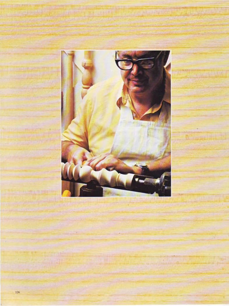
106

CHAPTER NINE
Turning Tools
Woodturning is one of the most enjoyable of
the woodcrafts; it allows the w oodw orker to be
completely creative
107
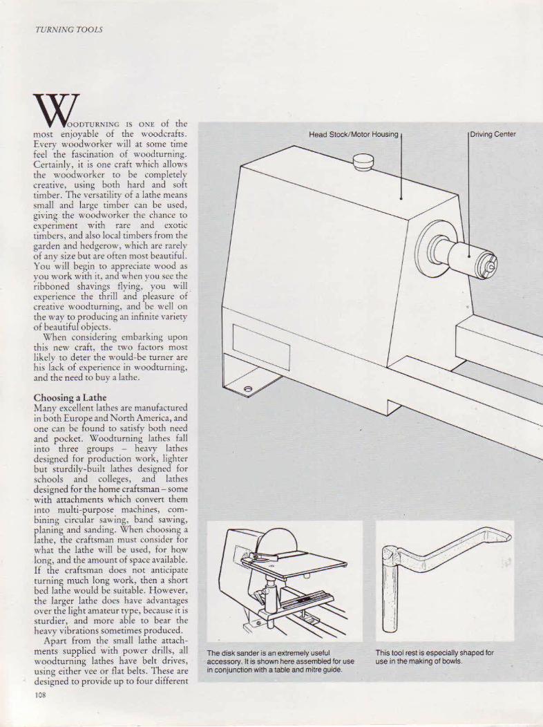
TURNING TOOLS
w.OTU"'I>!C IS ONE of the most enjoyable of the woodcrafts. Every woodworker will at some time feel the fascination of woodturning. Certain ly, it is one craft which alJows the woodworker to be completely creative, using both hard and soft timber. The versatility of a lathe means small and large timber can be used, giving the woodworker the chance to experiment with rare and exotic timbers, and also local timbers from the garden and hedgerow, which are rarely of any size but arc ofrcn most beautiful. You will begin to appreciate wood as you work with it, and when you sec the ribboned shavings flying, you will . experience the thrill and pleasure of creative woodcurning, and be well on the way co producing an infinite variety of beautiful objects.
When considering embarking upon chi~ new craft, the two faccors most likely to deter the would-be turner arc his lack of experience in woodturning, and the need to buy a lathe.
Choosing a Lathe Many excellent lathes are manufactured in both Europe and North America, and one can be found to satisfy both need and pocket. Woodcurning lathes fall into three groups - heavy lathes designed for production work, lighter but sturdily-built lathes designed for schools and colleges, and lathes designed for the home craftsman - some with attachments which convert them into multi-purpose machines, combining circular sawing, band sawing, planing and sanding. When choosing a lathe, the craftsman must consider for what the lathe will be used, for ho.w long, and the amount of space available. If the craftsman does not anticipate turning much long work, then a short bed lathe would be suitable. H.owever, the larger lathe does have advantages over the light amateur rype, because it is sturdier, and more able to bear the heavy vibrations sometimes produced.
Apart from the small lathe attachments supplied with power drills, aU woodturning lathes have belt drives, using either vee or flat belts. These are designed tO provide up to four different
lOS
Head Stock/ Motor Housing Driving Center
The disk sander is an extremely useful accessory. It is shown here assembled for use in conjunction with a table and mitre guide.
II This toot rest is especially shaped for use in the making of bowls.
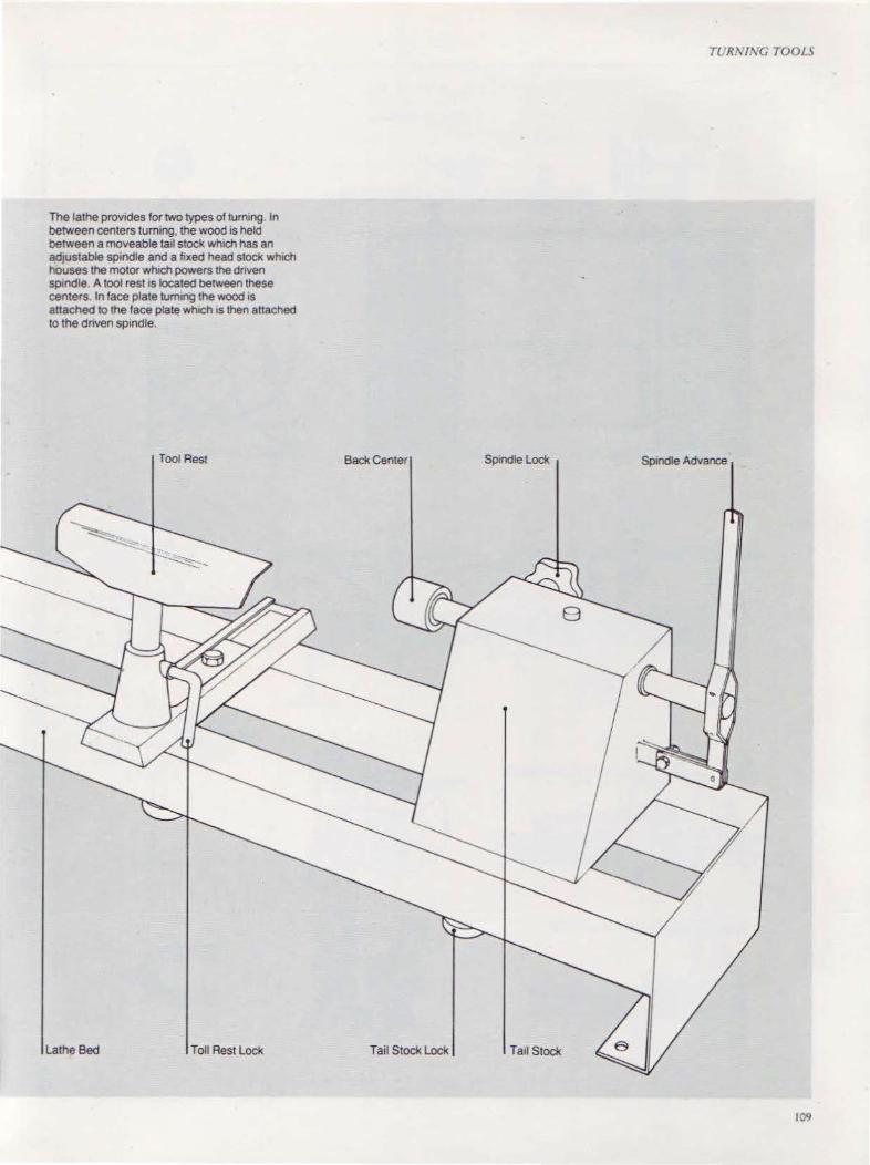
The lathe provides for two types of turning. In between centers turmng, the wood is held between a moveable tail stock which has an adjustable sp1ndle and a fixed head stock whiCh houses the motor which powers the dnven sptndle A tool rest 1s located between these centers In face plate tum1ng the wood is attached to the face plate whiCh 1s then attached to the dnven spindle.
Tool Rest
Lathe Bed Toll Rest Lock
Back Center
Tail Stock Lock
TURN ING TOOLS
Spindle Lock Spindle Advance
Tail Stock
109
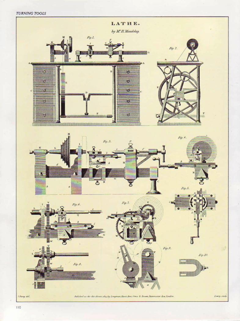
TURNING TOOlS
LAT II E.
M.
110

It would be idle to suggest that modern lathes are no more sophisticated than their ancestors, but the lathe from the early n~neteenth century, facing page, shows that basic principles have rema1ned the same. The multi-purpose mach1ne, above, comb1nes the functions of a lathe w1th those of a circular saw, a morticer. a planer and a sander.
speeds, ranging from roughly 500 rpm to 3000 rpm. Belt-changing devices vary and some are most difficult to operate. If money is no object, a lathe having a variable-speed drive, and operated by a lc'er or wheel, ~hould be considered. The final selection must be made in the knowledge that the lathe is supplied with a number of u eful work-holding attachments, and that it can be positioned in the workshop with sufficient room for the operator to work in comfort and safety.
Woodturning can be divided into two distinct work areas. When work is turned between centers, it is mounted between the head stock drive and the tail stock, and this is known as spindle turning. In face plate work, block~ are
TURNING TOOU
held either by the face plate or by various chucks, and are mounted on the head stock mandrel. Many lathes have a head stock spindle ~crewcd at both ends, enabling face plate work to be carried out on the outboard end, so that work of a larger diameter can be executed. One particular lathe has a rotating head which makes the assembly of larger work possible, and eliminates left- and right-hand face p lates.
The lathe selected must have an electric motor of adequate horsepower and be phased to suit the workshop supply. Any advice offered by the lathe supplier should be taken. The lathe must also be fitted with a switch of an approved type, positioned conveniently close to the left hand on the head stock.
Ill
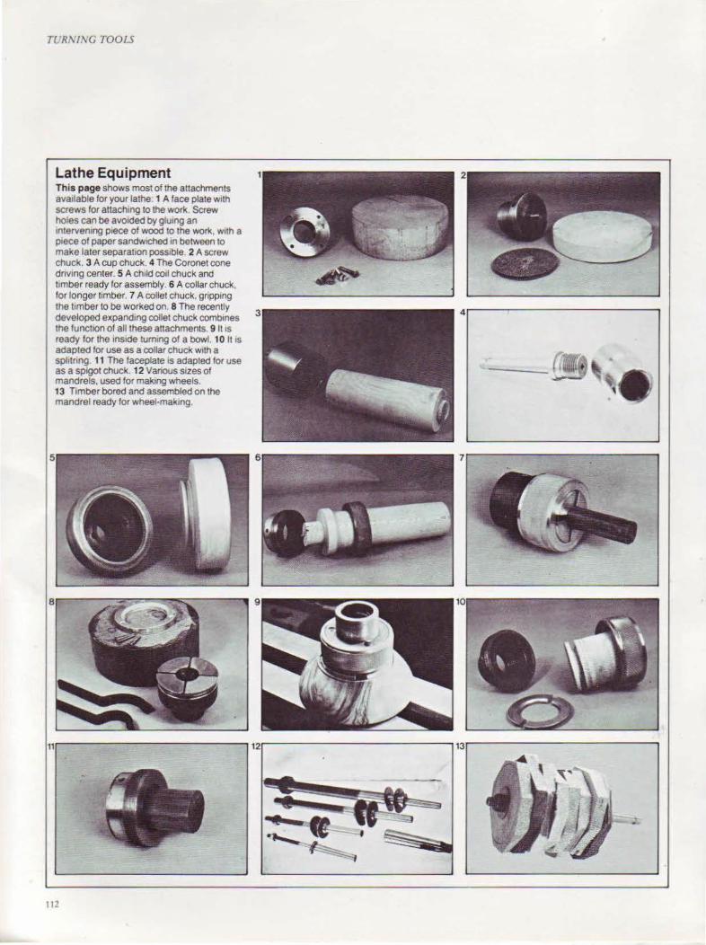
TUR\1\G TOOLS
Lathe Equipment This page shows most of the attachments ava1lable for your lathe: 1 A face plate w1th screws for attachmg to the work. Screw holes can be avoided by glu1ng an 1nterven1ng p1ece of wood to the work, w1th a p1ece of paper sandWIChed 1n between to make later separat1on poss1ble. 2 A screw chuck. 3 A cup chuck. 4 The Coronet cone dnvmg center. 5 A child coil chuck and t1mber ready for assembly. 6 A collar chuck, for longer timber. 7 A collet chuck, gripp1ng the limber to be worked on. 8 The recently developed expandmg collet chuck comb1nes the funct1on of all these attachments. 9 11 1s ready for the ins1de tum1ng of a bowl. 1 0 lt 1s adapted for use as a collar chuck w1th a sphtnng 11 The faceplate IS adapted for use as a sp1got chuck. 12 Vanous sizes of mandrels, used for making wheels. 13 T1mber bored and assembled on the mandrel ready for wheel-making.
Ill
3 4~----~---------------------,

Lathe Equipment .\lost lathe., are supplied with a number of standard component~. The dri,in~ ~:enter is either of the rwo or four-chi~cl '>tyle, with a morse taper to
suit rhc m.mdrel of the lathe. The dead center, either solid or cup,
al~o has a morse taper to suit the tail stock.
The perfect center is one which rot.lte'> (often called a running center), eliminating the need for lubricating grca.,c or oil.
One or two face plates are provided, usually with a larger one for the ourboard po.,ition. There is, ho~·eyer, little need for large face plates, .md 3-inch 75 mrn and 4-inch/ 1 00-mm wide plate~ will be ample.
Blocks for bowls, boxes and disht!~ can be held using the screw chuck.
This is also particularly useful for di!!k work and in the making of picture frame~.
Tlw collar chuck, of which there are !le,·cr.ll variations, is used m.unh for holding longer timber, and is ideall~ suited to the turning of egg cups, napkin ring~, slim vases and boxes. There is no possibility of the wood separating from the chuck, and holding holes arc eliminated.
One of the most significant ad,·ances in lathe design in recent years is the expanding collet chuck, designed and made by an English compam - Craft Supplies. Thi~ chuck eliminates the need for face plates or orher chuck!.. The e"panding collet means the turning is held in a dovetailed rece~s cut in the base. The chuck can be used as a collar chuck , when a split w,,~hcr i~ fitted into a ~roove cut in the timber which h.ls been previou.,J)' turned between centers. Long timber of any diameter within the capacity of the lathe can be accommodated. The back plate can ~erw as a face plate or a ~pigot chuck. A platl.' is also supplied to convert the chuck into a !!Cre\\ chuck.
A recenr addition to the\\ oodturner':. equipment are ground carbon steel mandrels. All have No 1 morse taper arbors and are centered at rhc other end to receive a revoh·ing center. Each mandrel is part-threaded and fitted with ~·asher and nut. 11le'>e arc ideal for turnm~ batches of tO\' " heel.,, ring~ and pepper mills and have a great number of other uses.
One of the great problems of the woodtu rncr arises when he has ro repeat an exact shape. Thi., occur~ most frequently in spindle work ''hen making
T(J R\IXC TOOH
The copying attachment solves the problem of how to reproduce exactly s1milar patterns on such 1tems as table and chair legs. Each of the adjustable f1ngers marks a particular part of the work When the pre·set d1ameter IS reached. the lingers drop out of use.
table .md chair legs. The latest device created ro simplify this is the rraft copying attachment, made by Craft 'upplie,.
It consist~ oi a long rube whith 1!>
!lcrewcd to the lathe base. Adjusr.1blc finger~ arc pla~:ed along the tube, each one marking a particular measured part of the work. Each i~ set up to an e\act diameter, the: mo,·ing part of the linger dropping when the ~tz.c is reached.
A complete!~ ne~ concept in th~ holding and dm ing of work bern em center~ i., the cone cemcr, made b' Coronet. Here, the dri,·ing fork in th.e head'ltock ha~ been substituted b\ a cone which i'> fitted with a mor~~ taper or, in th~ <.:a'>e of certain machine'>. ~.an be .,c;rewc:d on the lathe mandrel. The square: section timber is inserted into, and driven b), the cone. Cones ~ ith 1 ~-2 1h incht6-62mm capacitic~ are aY,lilable.
A similar Je.,ign which runs on a ball r.Ke i., av,,il,lble (or the tailstock .
The '>quared umber can b~ .H:commodarcd without end .. a~·ing or center popping. Round srock can al.,o bl' accommodated and if at anv rime the rounded job is taken out of ~he lathe, it can be rcplact:'d easily withou t having to be centered .
t D

TL:RNING TOOLS
The Turning Tools There are rwo distinct types of curring tools available for use on the lathe -those which cur on the skew, giving a slicing cut, and those which cut square on, givi ng a scraping cut. The !.mer group arc often referred £O as scrapers. and many people imagine, erroneously, that the scrapings should be dust, nor shavings. If we are to cut wood in the way it likes to be cut, with the wood having a polished finish from the cool, then these pure cutting tools must be used.
There arc three srylcs of turning tools which indicate size rather than shapelong and strong, standard and small.
Turning tools need stout handles in either beech or ash, and should ha\"e sufficient length and girth tO provide strength. At the same time, they must be StYled to take the hand comforrablv. Atrer gaining experience, many woodturners turn their own handles to suit their particular needs.
The reputable manufacturer forges his blades from high-quality carbon steel, which is skillfulh- and accuratch hardened and remper~d tO give long edge-holding qualines. There i~ an increasing tendency amongst some European manufacturers to use highspeed steel, ahhough there seems lirde advanta):;e in ·this.
Chisels for turning have bevels on both sides, and with the cutting edge sq uarc or skew, in sizes ranging from 1N-2 inchcs/6-SOmm.
A chisel for parting off, marking out and beading is the parting tool, but a 1/4-inch/6-mm square-ground chisel can be used for this work.
Skew Chisel
Square Chisel
Parting Chtset
The turning chisels illustrated, right, are. from left to right, the diamond. the 112·tnch/12·mm skew. three gouges. a parting chisel. a round nose and a 1-inch/25-mrn skew.
IJ.I

The deep long and strong gouges above, are useo espec1ally •n the ma-<.ng of bOwls to remove wOOd rap•dty.
Gougl:\ f.11l into three group' -'pindk gougl:'>, which .lrt' r.nh~·r :,h 1lhl\\ 111 \Cction .md used for work bet\\ ec.•n centers, Jeep \r.mdard -~izt.' ~ougc' fo r the same work, and J eep Iono .1ntl srron" vou<•c~. ~ t'tt'l ~
Shallo'' gouges. \\ ith ends rounded w thl: ,hape of the end of the link· finger, an: mt>d lor CO\ in~ ,md odll'r 'pindlo.: '' ork, .1nd .tf,o lor ... m.tll bm' f, .1nJ ,jmilar lace pl.ue \\ ork.
t\n l:''cnri.tl gouge for bo'' I '' ork, i, the deep long .md strong gouge. Thi' '' ~round ~qu.tre across, rhe ideal "idrh bctng '11 inch/ 9m m. It can abo lw mc.•d 111 'pindlc work .
Shallow Sp.ndle Gouge
F•nger NaJI Gouge
TUR.\'J,\'G TOOL~
/ )
( I
" '-----'1 Deep Sp•note Gouge
Deep Long and Strong Gouge
II'-
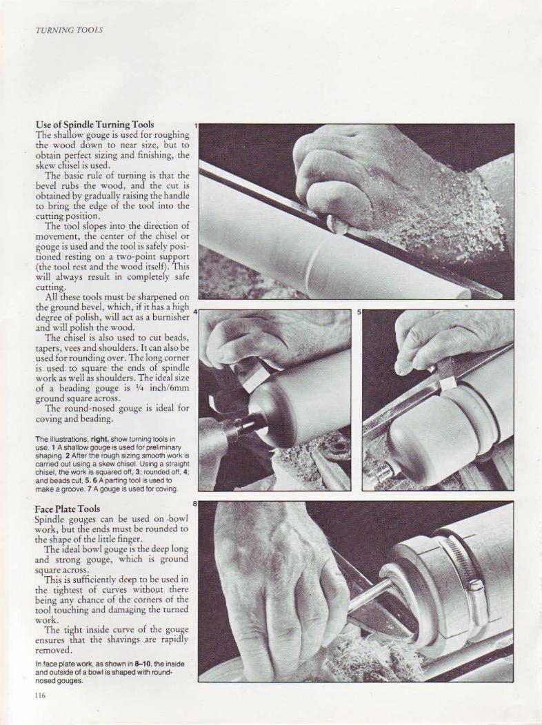
TURNING TOOLS
Use of Spindle Turning Tools 1
The shallow gouge is used for roughing the wood down to near size, but to obtain perfect sizing and finishing, the skew chisel is used.
The basic rule of turning is that the bevel rubs the wood, and the cut is obtained by gradually raising the handle to bring the edge of the tool into the cutting position.
The tool slopes into the direction of movement, the center of the chisel or gouge is used and the tool is safely positioned resting on a two-point support (the tool rest and the wood itself). This will. always result in completely safe cutung.
All these tools must be sharpened on the ground bevel, which, if it has a high
4,-----...,.....,..-
degree of polish, will act as a burnisher and wiU polish the wood.
The chisel1s also used to cut beads, tapers, vees and shoulders. It can also be used for rounding over. The long corner is used to square the ends of spindle work as well as shoulders. The ideal siz.e of a beading gouge is 1/ 4 inch/6mm ground square across.
The round-nosed gouge is ideal for caving and beading.
The illustrations, right, show turning tools in use. 1 A shallow gouge IS used for preliminary shaping. 2 After the rough sizing smooth work is earned out using a skew chisel. Using a stra1ght chisel, the work is squared off, 3; rounded ott, 4 . and beads cut, 5. 6 A part1ng tool is used to make a groove. 7 A gouge is used for coving.
Face Plate Tools Spindle gouges can be used on .bowl work, but the ends must be rounded to the shape of the little fin~er.
The ideal bowl gouge ts the deep long and strong gouge, which is ground square across.
This is sufficiently deep to be used in the tightest of curves without there being any chance of the corners of the tool touching and damaging the turned work.
The tight inside curve of the gouge ensures that the shavings are rapidly removed.
In face plate work, as shown in 8-10, the inside and outside of a bowl is shaped with round· nosed gouges.
116

TURN!l\'G 700LS
117
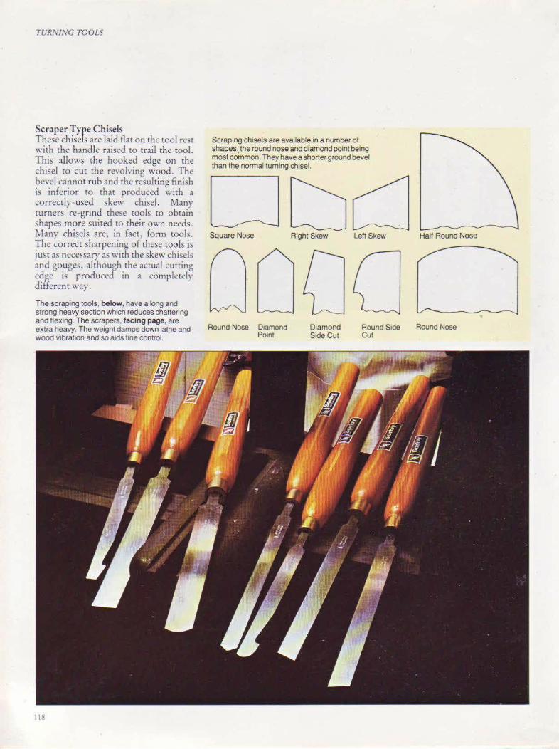
TURNING TOOLS
Scraper Type Chisels These ch isels are laid flat on the tool rest with the handle raised to trail the tool. This allows the hooked edge on the chisel to cut the revoking wood . The bevel can not rub and the resulting finish is inferio r tO that produced with a correcdy-used skew chisel. Many turners re-grind these tools to obtain shapes more suited to their own needs . Many chisels are, in fact, f<?rn1 rools. The correct sharpenino of these tools is just a:; necessary as with the skew chisels and gougcs, although the actual cutting edge is produced in a complcrdy different way.
The scraping tools, below, have a long and strong heavy section which reduces chattering and flex~ng. The scrapers, facing page, are extra heavy. The weight damps down lathe and wood vibration and so aids hne control.
Ill!
Scraping chisels are available.in a number of shapes, the round nose and diamond point being most common. They have a shorter ground bevel than the normal turning chisel.
Square Nose
Round Nose D1amond Point
Right Skew
Diamond Side Cut
Left Skew
Round Side Cut
Half Round Nose
Round Nose
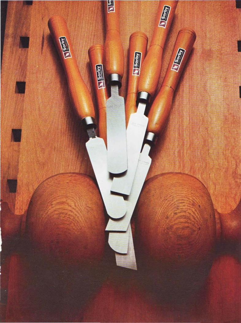

TURNING TOOLS
Boring on the Lathe Various boring tools arc necessary for \\'OOd mrning.
If table and standard lamps are ro be bored, a lamp standard sheU auger will be needed. They are usually 30 inches/ 750mm long and 1 o~ inch/6mm, 5/ 16
inch/ 8mrn, 3/A inch/ !Omm and 7/ 11, inch/ J lmm in diameter. This auger CULS
easily into end grain, irs center lip ensures the bit is central, and if the auger i!. withdrawn steadily to remove the
I An auger like the lamp standard shell auger, above, will make long holes for electric flex. Unless the tai I stock is designed to accept an auger, a long hole-boring attachment like the one, right, should be used. This will support the wood as it revolves and at the same time allow the auger to pass through. When boring large holes a tail stock chuck is used. It Is fitted w1th a morse taper and its capacrty must be at least 1/2
mch/12mm to accommodate saw-tooth machine bits like one below or similar machine bits such as the flatbit, below right.
120
waste, there is little possibility of ir running off-center.
Ideally, large holes for boxes and \'ases arc cut using the saw tooth machine cutter (multi-spur bit in the USA). This is a perfect rool for cutting end or side grain, in any type or condition of timber.
For boring pepper and salt mills, and holes up to 11h inch/37mm diameter, the flatb it is excellent. It must not be fed into end grain roo quickly, otherwise it
will run off-true. Holes of a smaller diameter can be
bored using nvo other types of bir - rhe wood drill and the lip and spur drill.
The wood drill is simi lar to the engineer's twist drill, but with a sharper no~e ,md greater chip clearance.
The lip and spur drill has chip clearance similar in design to the wood drill but has a brad point, rwo spurs to cut the periphery of the hole and cutters to cur and lift rhe chips.
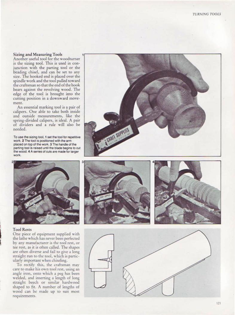
Sizing and Measuring Tools Another useful tool for the wood turner is the sizing tool. This is used in conjunction with the/aning tool or the beading chisel, an can be set to any size. The hooked end is flaced over the spindle work and the too pulled coward the craftsman so that the end of the hook bears against the revolving wood. The edge of the tool is brought into the cutting position in a downward movement.
An essential marking tool is a pair of calipers. One able to take both inside and outside measurements, like the spring-divided calipers, is ideal. A pair of dividers and a rule will also be needed.
To use the sizing tool, 1 set the tool tor repetitive won<. 2 The tool is pos1tloned with the arm placed on top of the WOI1t. 3 The handle of the parting tool is raised untll the blade begins to cut the wood. 4 A series of cuts are made for larger work.
Tool Rests One piece of equipment supplied with the lathe which has nc' er been perfected b~ an} manufacturer t'> the tool rest, or tee rest, as it is often called. The shape:> are often diverse and fail to give a long straight run to the tOol. which is particularly important when chiseling.
To rectify this, the craftsman ma\ care to make his 0\\ n cool rest, w.ing an angle iron, onto "hich a peg has been welded, and inserting a length of long straight beech or similar hard wood shaped to fit. A number of lengths of wood can be made up to suit mo~t reqUirements.
TURNING TOOLS
1.!1
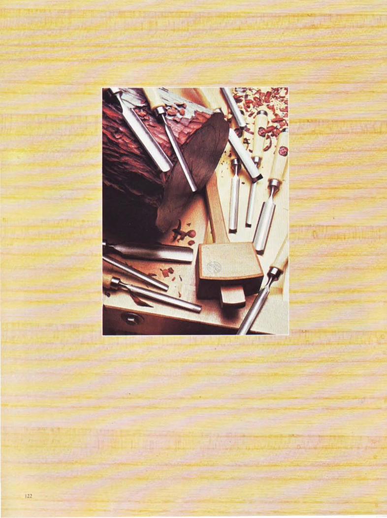
CHAPTF.R TF..V
Carving Tools Carving is not only
a very serious and skilled craft, it has also been rwidely taken up
as a hobby.
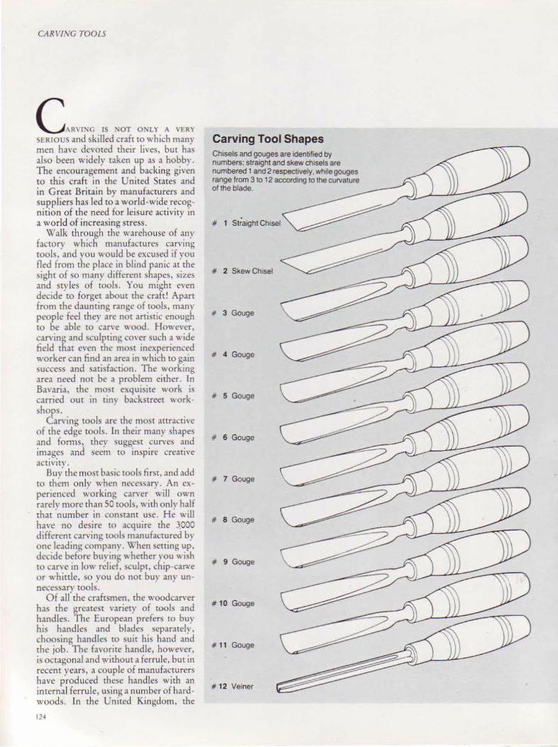
CARVIJ\G TOOLS
C,."'G IS 'OT O'LY A ""' SI:RIOUS and skilled craft to"' hich many men have devoted their lives, but has also been widely taken up a~ a hobby. The encouragement and backing given to this craft in the United States and in Great Britain bv manufacturers and suppliers has led td a world-wide recognition of the need for leisure activity in a world of increasing stress.
Walk through the warehouse of any factory which manufactures carving tools, anc.l you would be excused if you fled from the place in blind panic .u the sight of so many different l>hapc~, sizes and styles of tools. You might even decide to forget about the craft! Apart from the daunting range of tools, many people feel they are not artistic enough to be able to can·e wood. Howc,·cr, can•ing and ~culpting CO\er such a" ide field that even the most inexperienced worker can find an area in which to gain success and satisfaction. The working area need not be a problem either. In Bavaria, the mo~t exquisite work i-; carried out in ttn\ b.tckstreet work~hops.
Carving tools are the rno~r attracrivc of the edge tools. In their many shapes and forms, they suggest curves and irn~g~s and seem ro inspire creative aCtiVIt}'.
Buv the most ba~ic cools firsr, and add to th~m only when nccc\sary. An cxperiem:ed working carver will own rarely more than 50 tools, with only half that number in constant use. He will have no desire ro acquire the ~000 different carving tools manufactured by one leading company. When setting up, decide before buving whether you wish to can.e in low relief, s..:ulpt, chip-carve or whittle, so you do not buy any unnece~sary tools.
Of all rhe craftsmen, the woodcarver has the greatest ,·ariecy of tools and handles. The European prefers to buy his handles and blade') l.cparately, choo~ing h.tndb to \uit his hand and the job. The favorite handle, however. is octagonal and without a ferrule, bur in recent years, a couple of manufacturers have produced the~c handles with an internal ferrule, using a number of hardwoods. In the United Kingdom, the
1.?4
Carving Tool Shapes Chisels and gouges are identified by numbers; straight and skew chtsels are numbered 1 and 2 respectiVely. while gouges range from 3 to 12 according to the curvature of the blade.
# 1
# 2 Skew Chisel
# 3 Gouge
# 4 Gouge
# 5 Gouge
# 6 Gouge
# 7 Gouge
# 8 Gouge
# 9 Gouge
# 10 Gouge
# 11 Gouge
# 12 Veiner

Straight gouge: This has a straight blade in line w1th the handle.
Bent or curved gouge: A gouge w1th an upturned curve to the blade; used for working the 1ns1de of concave shapes.
Spoon or front bent gouge: S1m1lar to the bent gouge but with a more pronounced curve to the front section of the blade; used lor deep concave shaping.
Back bent gouge: Similar to the spoon gouge, but bent so that convex shapes can be worked.
Fishtail gouge: Shaped like a hshta1l, this gouge is used for making sharp edges and corners.
Parting tool : This has a V-shaped cutting edge; used lor groovmg and marl<1ng out low-relief work. It IS available m three shapes -obtuse. medium and acute
CA RVING TOOL<;
1.25
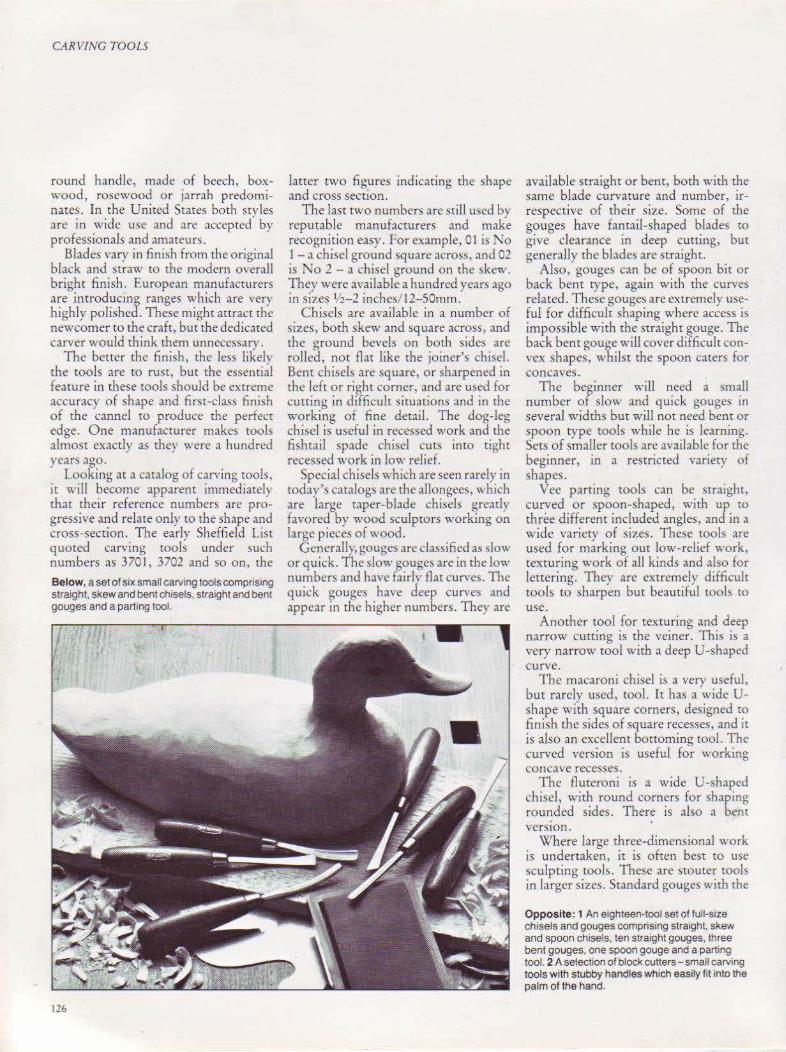
CARVING TOOLS
round handle, made of beech, boxwood, rosewood or jarrah predominates. In the United States both sryles are in wide use and are accepted by professionals and amateurs.
Blades vary in finish from the original black and straw to the modern overall bright finish. European manufacturers are introducing ranges which are very highly polished. These might attract the newcomer to the craft, but the dedicated carver would think them unnecessary.
The better the finish, the less likely tbe tools are to rust, but the essential feature in these wols should be extreme accuracy of shape and first-class finish of the cannel to produce the perfect edge. One manufacturer makes tools almost exactly as they were a hundred years ago.
Looking at a catalog of carving tools, it v.·ill become apparent immediate!) that their reference numbers are progressive and relate only w the shape and cross-section. The early Sheffield List quoted carving tools under such numbers as 3701, 3702 and so on, the
Below, a set of six small carving tools comprising straight, skew and bent chisels, straight and bent gouges and a parting tool.
126
latter two figures indicating the shape and cross section.
The last two numbers are still used by reputable manufacturers and make recognition easy. For example, 01 is No I- a chisel ground square across, and 02 is No 2 -a chisel ground on the !>ke~v. They were available a hundred years ago in size~ 1/2-2 inches/ 12-SOmm.
Chisels are available in a number of sizes, both skew and square across, and the ground bevels on both sides are rolled, not flat like the joiner's chisel. Bent chisels are square, or sharpened in the left or right corner, and arc used for cutting in difficult siruations and in the working of fine derail. The dog-leg chisel is useful in recessed work and the fishtail spade chisel cuts into tight recessed work in low relief.
Special chisels which are seen rarely in roday's catalogs are the allongees, which are large taper-blade chisels greatly favored by wood sculptors working on large pieces of wood.
Generally, gouges are classified as slow or quick. The slow gouges are in the low numbers and have fairly flat curves. The quick gouges have deep curves and appear in the higher numbers. Ther are
available straight or ben t, both with the same blade curvarure and number, irrespective of their size. Some of the gouges have fantail-shaped blades ro give clearance in deep cutting, but generally the blades arc straight.
Also, gouges can be of spoon bit or back bent type, again wirh rhe curves related. These gouges arc extremely useful for difficult shaping where access is impossible with the straight gouge. The back bent gouge will cover difficult convex shapes, ·whilst the spoon caters for con caves.
The beginner will need a small number of slow and quick gouges in several widths but will not need bent or spoon type tools while he is learning. Sets of smaller tools are available for the beginner, in a restricted variety of shapes.
Vee parting tools can be straight, curved or spoon-shaped, with up ro three different included angles, and in a wide variety of sizes. These tools are used for marking out low-relief work, texturing work of all kinds and also for lettering. They arc cxtn.:mely difficult tools to sharpen but beautiful roob ro use.
Another tool for texturing and deep narrow cutting is the veiner. This is a very narrow tool with a deep U-shaped curve.
The macaroni chisel is a very useful, bur rarely used, tool. It has a wide Ushape with square corners, designed ro finish the sides of square recesses, and it is also an excellent bottoming wol. The curved version is useful for working concave recesses.
The flureroni is a wide U-shaped chisel, with round corners for shaping rounded sides. There is also a bent version.
Where large three-dimensional work is undertaken, it is often best to use sculpting roob. These arc stotlter tools in larger sizes. Standard gouges with the
Opposite: 1 An etghteen·tool set of full-size chisels and gouges comprising straight, skew and spoon chisels, ten straight gouges, three bent gouges, one spoon gouge and a parting tool. 2 A selection of block cutters- small carving tools with stubby handles which easily lit into the palm of the hand.

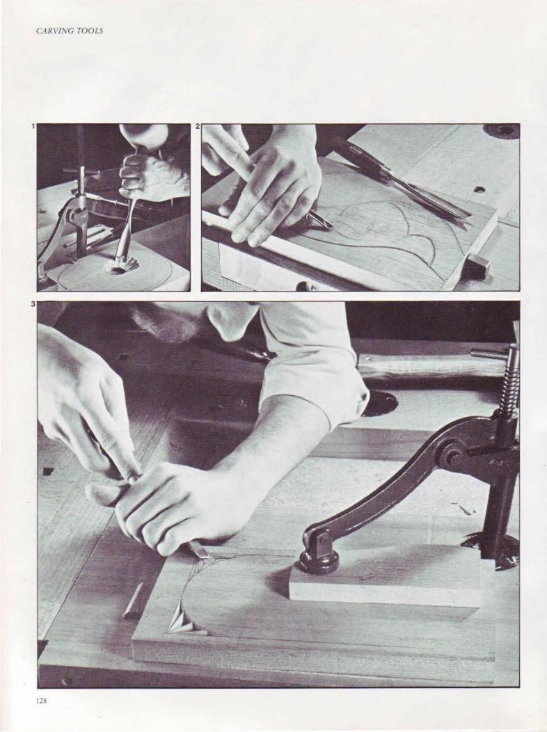
CAR\ JivC TOOlS
128
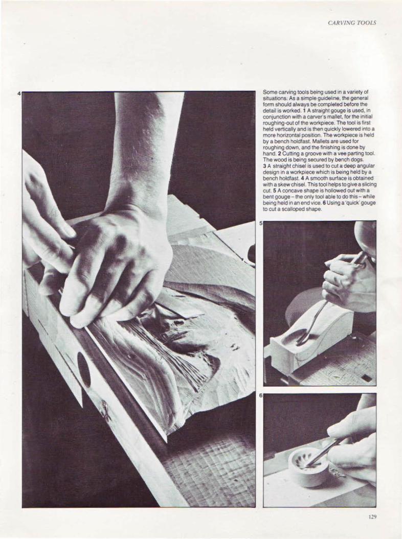
CA RVING TOOLS
Some carving tools being used in a variety of situations. As a simple gu1deline, the general form should always be completed before the detail is wot'Ked. 1 A straight gouge is used, 1n conJunction w1th a carvers mallet, for the in1t1al roughing-out of the workp1ece. The tool is first hetd vert1cally and IS then quickly lowered tnto a more honzontal posrt10n. The workpiece IS held by a bench holdfast. Mallets are used for rough1ng down, and the finishing is done by hand. 2 Cutting a groove with a vee parting tool. The wood is being secured by bench dogs. 3 A straight chisel is used to cut a deep angular design in a workpiece which is being held by a bench holdfast. 4 A smooth surface is obtained With a skew chisel. This tool helps to give a shCtng cut. 5 A concave shape IS hollowed out with a bent gouge- the only tool able to do this- wh1le being held in an end v1ce. 6 Us1ng a ·quick' gouge to cut a scalloped shape
129

CARVING TOOLS
Top, a twelve-tool set of light carving tools. These are the same quality as the full-size tools but are smaller and lighter. The mallet has a Ugnum vitae head and an ash handle.' Above, carving planes are available with flat, curved and spoon soles and are used for fine finishing work. Right, a quick way to rough down and remove waste is to use a flatbit attached to a power drill. Far right, the carver's adz is a more traditional tool for quickly removing waste. This adz has a small blade, 2 iAches/SOmm wide and an 8Y2·inch/212-mm long ash handle.
130
normal tanged blade and wooden handle are popular with sculptors. One range has long blades and standardlength handles, often with leather caps. They will stand up to the very heaviest work.
Many carvers, particularly in North America, use knives only, with great skill. This is called whittling - a term which suggests that little skill and attention to detail is needed. However, this impression is quite wrong, and can be proved so by inspecting whittled wood. The knives used are of high -quality steel, and are available in a varierv of blade shapes to meet the needs of the whittier.
The carving of domestic ware such as dishes, trays and bowls can usually be done with the normal carving tools. The bowls of small spoons and suchlike can be cut with the carver's hook.
In the past, the hook had a long handle which could be tucked under the ann . The modern version is adequate for small work and can be used for scooping out curved recesses. A similar tool is the scorp, which has a circular blade.
A collection of beautiful tools which became available recently ~re carving planes, 1 Vs inches/28mm long and I inch/25mm wide. With polished metal bodies and integral handles which extend comfortably into the palm of the hand, these planes arc available in three sole styles - flat, lengthwise curYe and spoon. When correctly sharpened and finely set, they are capable of the finest finishing work.
Many carvers and wood sculptors working on large forms need a carver's adz for the speedy roughing-down and removal of waste. This is
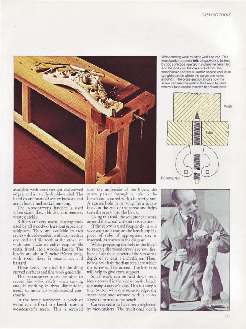
available with both straight and cun ed edges, and is usually double-ended. The handles are made of ash or hickory and are at least 9 inches/225mm long.
The woodcarver's hatchet is used when sizing down blocks, a~ it remove<, waste quickly.
Rifflers are very useful shaping tools used by all woodworkers, but especiall) sculptors. They are available in two styles- double-ended, with rasp teeth at one end and file teeth at the other, or with one blade of either rasp or file teeth, tined into a wooden handle. The blades are about 2 inches/SOmm long, with tooth sizes in second cur and bastard.
These tools are ideal for finishing curved surfaces and fine work generall) .
The woodcarver must be able to secure hi~ work safely when carving and, if working in three dimensions, needs to move his work around constantly.
In the home workshop, a block of wood can be fixed to a bench, using a woedcarver's screw. This is screwed
imo the underside of the block, the screw passed through a hole in the bench and secured with a butterfly nut. A square hole in its wing firs a square boss on the end of the screw and helps turn the screw intO the block.
Using rhis tool, the sculptor can work around the wood without obstruction.
If the screw is used frequently, it will sa\·e wear and tear on the bench top if a piece of rube of appropriate size is mserted, as shown in the diagram.
When preparipg the hole in the block to receive the woodcarver's screw, fir t bore a hole the diameter of the screw ro a depth of at least I inch/2Smm. Then, bore a hole half the diameter, into which the screw will be turned. The first hole will heir to give extra support.
Smal work can be held down on a block secured in the' tee or on the bench top using a can·er's clip. This is a simple turn bunon with one serrated edge, the other bent and serrated with a center screw to tum into the bench.
Carvers seem to have been neglected by vice-makers. The traditional vice is
CARV!l\'G TOOLS
Woodcarving work must be well· secured This woodworker's bench.left, allows work to be held by dogs or stops 1nserted m slots in the bench top and the end v1ce. Below and bottom, the woodcarver's screw IS used to secure work n an upnght pos111on where the carver can move arbund 11 The cross·sect10n shows how the screw secures the work to tne bench top and where a tube can be 1nserted to prevent wear
131
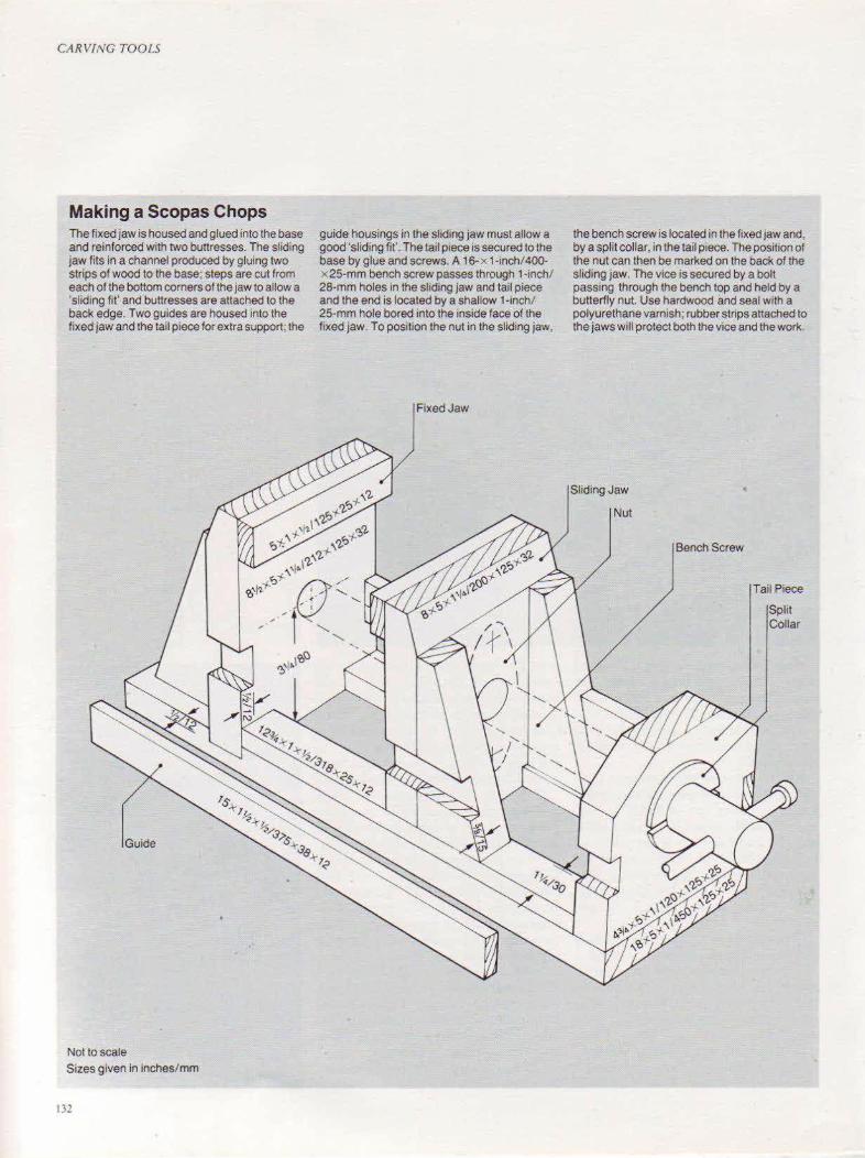
CA RV!t'IG TOOLS
Making a Scopas Chops The fixed jaw is housed and glued into the base and reinforced with two buttresses. The sliding jaw fits in a channel produced by gluing two strips of wood to the base; steps are cut from each of the bottom comers of the jaw to allow a 'sliding fit' and buttresses are attached to the back edge. Two guides are housed into the fixed jaw and the tail piece for extra support; the
Guide
Not to scale Sizes given in inches/ mm
132
guide housings in the sliding jaw must allow a good 'sliding fit'. The tail piece is secured to the base by glue and screws. A 16-x 1-inch/400. x 25-mm bench screw passes through 1-inch/ 28-mm holes in the shd1ng jaw and tail piece and the end is located by a shallow 1-lnch/ 25-mm hole bored into the inside face of the fixed jaw. To position the nut in the sliding jaw,
Fixed Jaw
the bench screw is located in the fixed jaw and, by a split collar, in the tail p1ece. The position of the nut can then be marked on the back of the sliding jaw. The vice is secured by a boll passing through the bench top and held by a butterfly nut. Use hardwood and seal with a polyurethane varnish; rubber strips attached to the jaws will protect both the vice and the work.
Sliding Jaw
Nut
Bench Screw
Tail Piece
Split Collar
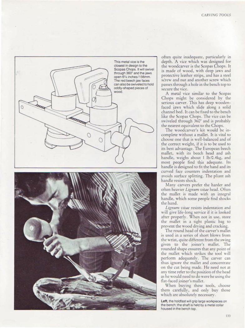
ThiS metal VICe IS the closest in des1gn to the Scopas Chops. It will sw1vel through 360° and the jaws open 6''4 inches/156mm. The red beech jaw faces can also be sw1veled to hold oddty·shaped pieces of Wood.
CARV/1\'G TOOLS
often quire inadequate, particularly in depth. A vice which was designed for the woodcarver is the Scopas Chops. It is made of wood, with deep jaws and protective leather strips, and has a sted ~crew and nut and another screw which passes through a hole in the bench wp tO \Ccure the vice.
A metal vice similar to the Scopas Chops might be considered by the serious carver. This has deep woodenfaced jaws which slide along a solid channel bed. It can be fixed to tht• bench like the Scopas Chops. The vice c,m be S\\ iveled through 360° and is probabl} the nearest equivalent to the Chops.
The woodcarver's kir would be incomplete without a mallet. Tt is viral ro choo!>e one that is well-balanced and of the correct ~·eight, 1f ir is to be U\ed tO
it-, best advantage. The European beech mallet, with its beech head and ash handle, weighs about I lb/0.4kg, and most people find this adequate. Irs handle is designed to fit the hand and irs curved face counters indentation and avoid~ surf,tce plming. The pliant ash h.tndlc resists ~hock.
\lany carvers prefer the harder and often heavier Lrgnum 'l.'itae head. Often the mallet is made with an integral handle, which )Ome people find shocks the h.md.
Lignum 'l.'it.te resists indentation and \\ill give life-ion~ \ervice if it i' looked after proper!~. \\'hen not in U\C, MOre the mallet in a tight pla!>tic bag to
prevent the wood drying and cr.lcking. The round head of the carver'!> mallet
is used in a seric~ of short blow!> from the wrist, quite different from the ~wing gi' en to the JOiner's m.tlle£. The rounded shape cn\ures that any point of the mallet which mikes the tOol "·ill perform adequately. The carver can thus ignore the mallet and concentrate on the cut being made. He need not at am time refer to the po~ition of the head a' he would need to do were he u<~in~ the tlat-faccd joiner\ malice.
\X'hen buying these tools, choose them carefuU\', and onlv bu,· those '' hich are absolutely nece;sary. ' Left, the holdfast w1ll gnp large workp1eces on the bench; the shaft ts held by a metal collar housed in the bench top
133
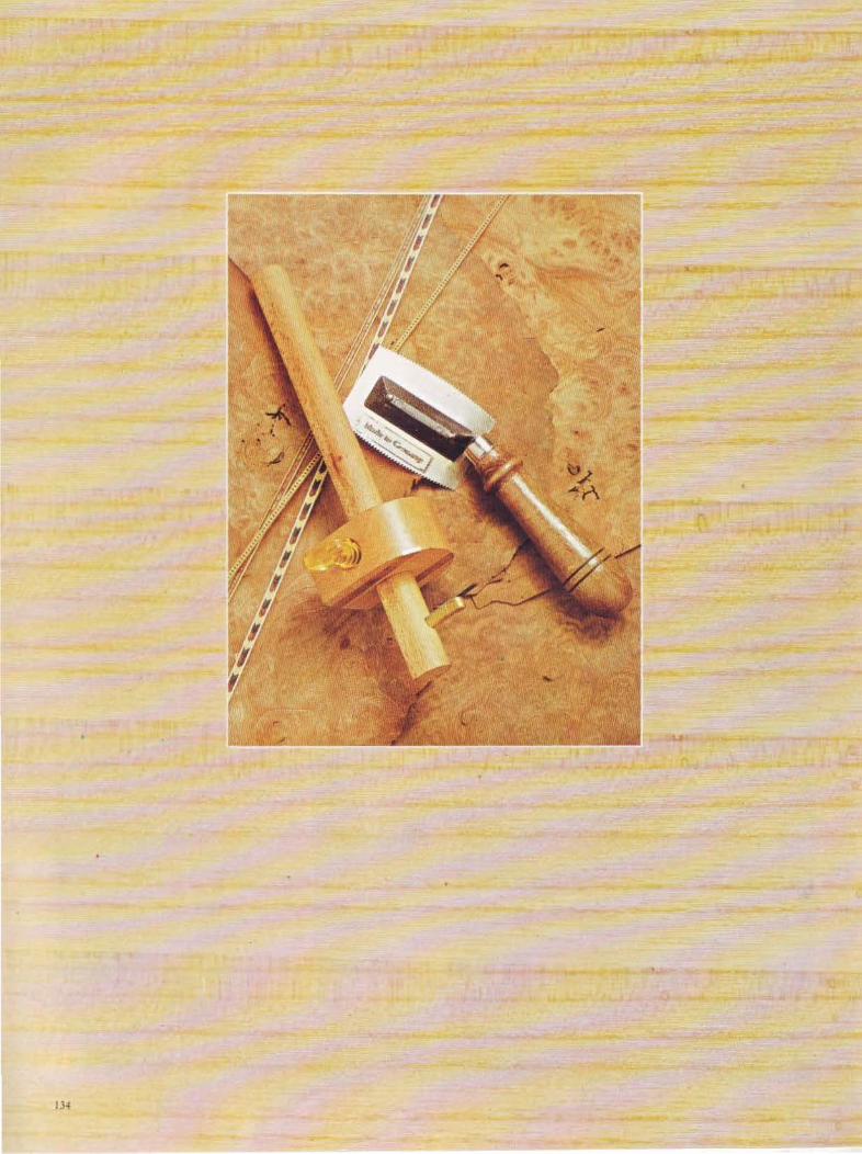
IJ.f
CHAPTER ELEVEN
Veneering Tools Nearly all the trees
giving beautifully colored and grained timber
can be obtained in veneer form.
135

\TVF[RINC TOOLS
Y HRING <OVI 0 RE O"CR!RfO" co,·ering over a poor- or inferiorgrained timber with a thin laver of more decorative wood. However: this is not strictly true when dc~cribing ~omc of the \ery beautiful veneered work of the past, where skilled constructional work demanded high-qu,1liry timber like mahogany. ·
Nearly all the trees gi\'ing beautifullycolored and grained timber can be obtained in veneer form. Many timbers from the smaller tree'> would not mher" ise be seen.
Veneers are made by either peeling or slicing the log, ~o the majority of the timber log is used. The slicing method produces 'figure' "hich, in timbers like oak. i~ described as ih ergrain.
In the pa'>t, \Cnecring was '>hrouded in a 'eil of nwstcr. , and the nece~ an tool' were not readih available. Tod;n·, m.10\· man-m.1de boards are veneered, using the traditional methods, and are used in the mass production of furniture. ~Ian-made boards, like multi-phwood,, make excellent ba~c matcriab for the home craftsman to veneer.
Inlays and Marquetry Banding is another form of veneering, where many tiny pieces of veneer are placed together £O form a pattern. The machine method of making banding i~ to ~lue long strips of timber ed~e to edge and then to sa\\ thl· wood ,\cross the grain into thin strips. These long patterned strips can be used with \'Cneers or they can be placed in shallow grooves in solid timber either as a decorative border or in geometric or other patterned form.
Veneer~ arc used to make up pictur~~ in a craft kno,,n as marquetry. Here, both the color and gram give scope to the artist craft!>man. The absence of colors like bright green~ and magentas is -.ohed by using dyed umbers, sycamore being a particularly popular timber for thl.., purpo~c.
The cool~ of the cralt can be broadly di' ided into two group~ - tho~e for cutting and those for laying. The extreme thin ness of veneers means that many of the traditional timber-cutting roob cannot be used.
136
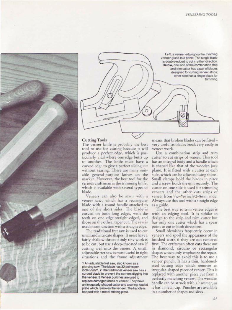
Cuttin g Tools The veneer knife is probably the best wol to usc for cutting because it will produce a perfect edge, which is particularly vital where one edge butts up to another. The knife must have a curYed edge to gi-.e a perfect ~tieing cut without tearing. There arc many suitable general-purpose knives on the market. Howe,·er, the best tool for the serious craftsman is the trimming knife, which is available with several types of blade.
Veneers can also be \awn with a ' 'eneer saw, which h,l\ a rectangular blade with a round handle attached w one of the short sides. The blade is curved on both long edges, with the teeth on one edge straight-edged, and those on the other, taper cut. The saw is used in conjunction" ith a straight edge.
The traditional fret ~aw is used to cut small and intricate shape\. It must have a fairly shallow throat if onl} tiny work is to be cut, but use a deep-throated saw if cutting well into the veneer. A small, adjustable fret saw is most useful in tight situations and the frame adjustment
1 An adjustable fret saw. also known as a ptercmg saw. The blade has 32 potnts per tnch/25mm. 2 The traditiOnal veneer saw has a curved blade to prevent the corners digging into the veneer. 3 Veneer punches are used to replace damaged areas of veneer. They have an irregularly-shaped cutter and a spring-loaded plate which removes the veneer. The handle is hooped with a metal striking plate.
\'1: \'££RING TOOLS
Lett. a veneer edging tool for trimming veneer glued to a panel. The single blade is double-edged to cut in either dtrecttOn. Below, one side of the combination stnp
and tnm cutter has a pair of blades destgned for cutting veneer stnps.
other stde has a smgle blade for tnmmmg
means th,u broken blades can be fitted very useful as blades break very easil) in veneer work.
Use a combination strip and trim cuner to cut strips of veneer. This wol bas an intel?ral body and a handle which is shaped ltke that of the wooden jack plane. lt is fitted with a cutter at each side, which can be adjusted using shims. Small clamps hold the blades in place and a screw holds the unit securely. The cutter on one side is used for tri~ming veneers and the other cuts strips of veneer from 1/u - Sft6 inch/2-~mm wide. Alwa)' usc thi., tool with a straight edge as a guide.
The best ~ ay to trim veneer edges is with an edging tool. It is similar in design to the strip and trim cutter but has only one cutter which has a spear point to cut in both directions.
Small blcmi~he~ frequently occur in veneer~ and spoil the appearance of the finished work if they are not removed first. The craftsman often cuts these out in diamond, circular or rectangular shapes which only emphasize the repair. The best way to avoid this is to use a ' 'cnccr punch. lt has a thin, hardenedsteel cutting edge ,-.hich remo,·es an irregular-shaped piece of \'eneer. This ts replaced with another piece cut from a perfectly matching ,·eneer. The wooden handle can be struck with a hammer, as it has a metal cap. Punches arc :lVailable in a number of shapes and sizes.
137
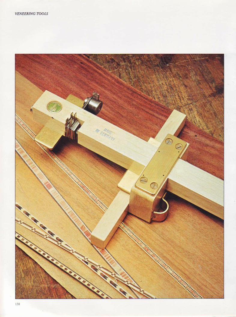
VENEERING TOOLS
138

Inlaying Tools The cutting gauge. is the tool most commonly used for cutting grooves for inlays and beading. It has a small cutter, shaped to cut in both directions with a slicmg action, and a stock which can be set at any distance along the beam and !occured in place with a thumbscrew. The cutting gauge can be converted into a scratch stock, which has a small cutter to cut a narrow groove into which an inlay and banding is glued.
A scratch stock can be made using rwo pieces of timber, a number of small bolts and a cutter made from an old hacksaw blade.
The inlay cutter is a superb German tool, made of beech and brass, which is used to cut shallow straight or curved grooves to receive inlays. The fence is adjustable up co 6 inches/ ISOmm from the edge of the work with veins between lfn-Sf t6 inch/2-Smm wide. It has rwo
blades wh ich cut the sides and another which removes the waste berween the veins. Shims give minute adjustments. This tool is a perfect example of a tool designed to meet a specific need exactly.
A tool designed for \' iolin-makers, but \vhich is equally suitable for general craftsmen is the purfling cutter. This is capable of cutting very small rebates and grooves.
The correct tool, as sharp as possible, must be used if veneering, inlaying and banding is to be done with complete \Uccess. Veneering ill an intricate craft, but extremely accurate marking out and cutting will contribute greatly to its final perfection. The special inlay cutter. facing page, is designed to cut narrow grooves With two cutter blades in oonjunction with the clearing-out cutter. The cutter of the pur1hng tool, right, is held and adjusted by two opposing screws. It is used to cut small rebates and grooves on stringed instruments, as shown below.
VENEERING TOOLS
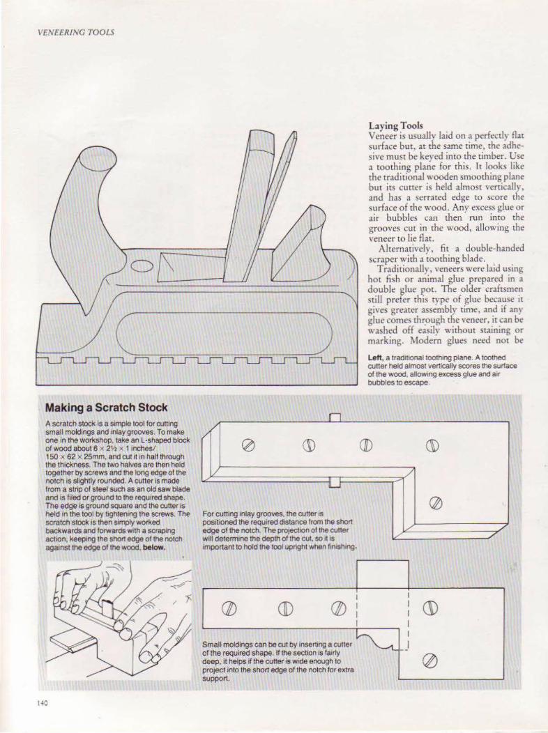
VENF£RING TOOLS
Making a Scratch Stock A scratch stock Is a Simple tool for cutting small moldings and mlaygrooves. To make one in the workshop, take an L·shaped block of wood about 6 x 2h x 1 inches/ 150 x 62 x 25mm. and cut 11 tn half through the th1ckness. The two halves are then held together by screws and the long edge of the notch is slightly rounded. A cutter Is made from a stnp of steel such as an old saw blade and is filed or ground to the required shape. The edg·e is ground square and the cutter ts held 1n the tool by 1tghten1ng the screws. The scratch stock IS then sunply worked backwards and forwards w1th a scraping actton, keep1ng the short edge of the notch
n /
0 (1)
1/
For cutting inlay grooves, the cutter is positioned the required d1stance from the short edge of the notch. The prOJection of the cutter will determrne the depth of the cut, so 11 is
aga1nst the edge of the wood, below. 1mportant to hold the tool upnght when fin1sh1ng.
I
(/f) GD (//) I I I
Laying Tools Veneer is usually laid on a perfectly flat surface but, at the same time, the adhesive must be keyed into the timber. Use a coothing plane for this. It looks like the traditional wooden smoothing plane but its cutter is held almost venicallv, and has a serrated edge to score the surface of the wood. Any excess glue or air bubbles can then run into the grooves cut in the wood, allowing the veneer to lie flaL
Alternatively, fit a double-handed scraper with a tooching blade.
T radirionally, veneers were laid using hot fish or animal glue prepared in a double olue por. The older craftsmen still prefer this type of glue because ir gives greater assembly rime, and if any glue comes thr.ough the veneer, it can be washed off easily without staining or marking. \1odern glues need not be
Left, a tradrtional toothing plane. A toothed cutter held almost vertically scores the surface of the wood, allowrng excess glue and aJr bubbles to escape.
(/[) ~
~7
@
I/ / I/ /
I I G) I I
Smal~ moldings can be cut by Inserting a cutter ~ I _ _I of the required shape. If the section is fairly
0 deep, it helps if the cutter is wide enough to project into the short edge of the notch for extra support.
140
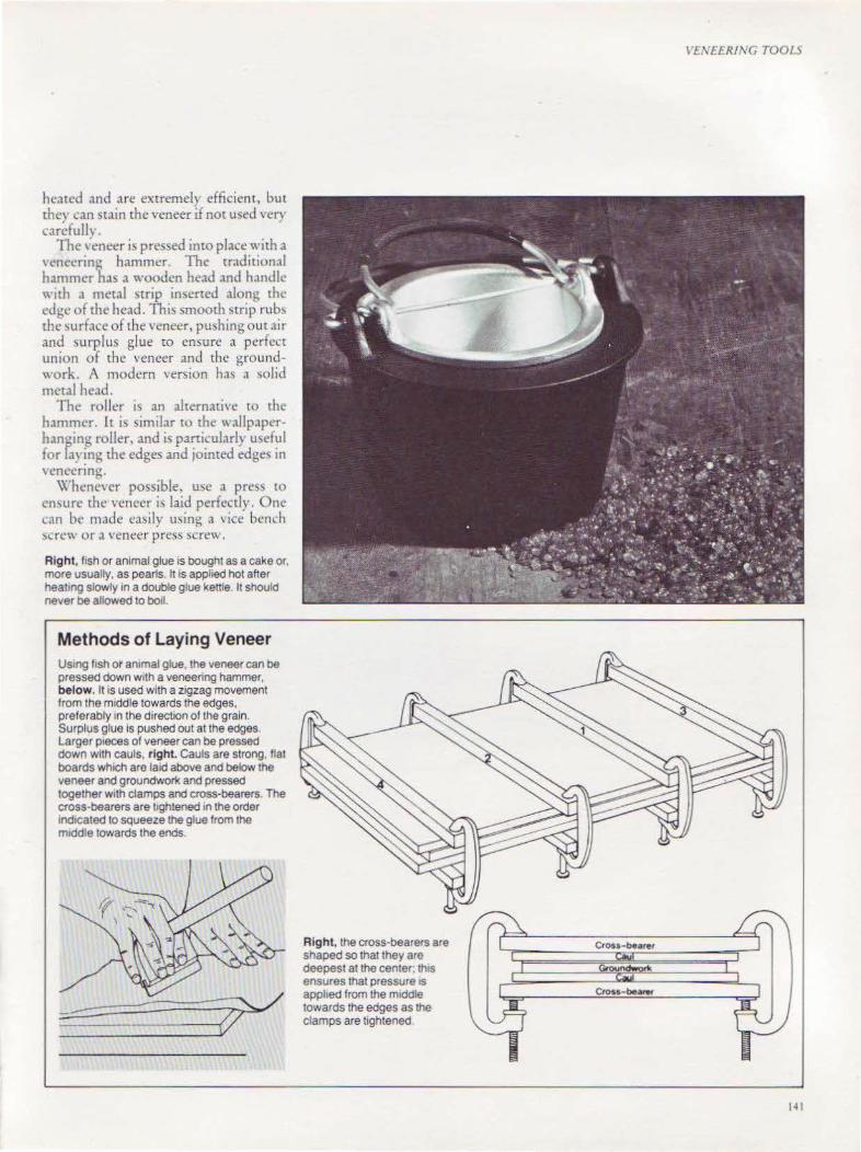
heated and are extremely efficient, but thev can stain the veneer J not used very carcfullv.
The ,·eneer is pressed into place with a ,·cnccrin<> hammer. The traditional hammer has a wooden head and handle with a metal strip inserted along the edge of the head. This smooth strip rubs the ~urface of the veneer, pushing out air and ~urplus glue ro ensure a perfect union of the veneer and the groundwork. A modern version has a solid metal he.1d.
The roller is an alternative to the hammt•r. lt is similar w the wallpaper hanping roller, and is particularly useful for lay~ng the edges and jointed edges in \'CnCCnng.
Whenever possible, me a press to cnsu re the veneer is laid perfect! y. One can be made easily using a 'icc bench ~acw or a veneer press screw.
Right, fish or animal glue is bought as a cake or, more usually, as pearls. tt is applied hot after heat1ng slowly in a double glue kettle. It should never be allowed to boil.
Methods of Laying Veneer Us1ng f1sh or ammalglue. the veneer can be pressed down with a veneering hammer, below. It is used with a zigzag movement from the middle towards the edges, preferably in the direction of the grain. Surplus glue is pushed out at the edges. Larger p1eces of veneer can be pressed down with cauls, right Cauls are strong, flat boards which are laid above and below the veneer and groundwOl'k and pressed together with clamps and cross-bearers. The cross-bearers are tightened in the order md1cated to squeeze the glue from the m1ddle towards the ends.
Right, the cross-bearers are shaped so that they are deepest at the center; th1s ensures that pressure IS applied from the m1ddle towards the edges as the clamps are tightened.
~'£.\'EER/1\'G TOOl S
Cross-bearer
Cross-be-
141
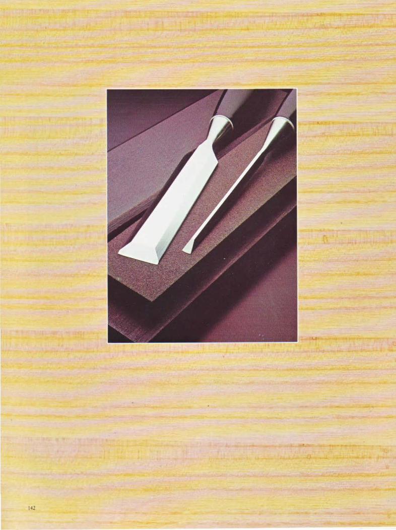
1-!l

CHAPTER T\t'El.VE
Maintenance Perhaps the greatest
deterrent to success with woodworking
tools is not keeping then1 perfectly ground and
sharpened.
1.0
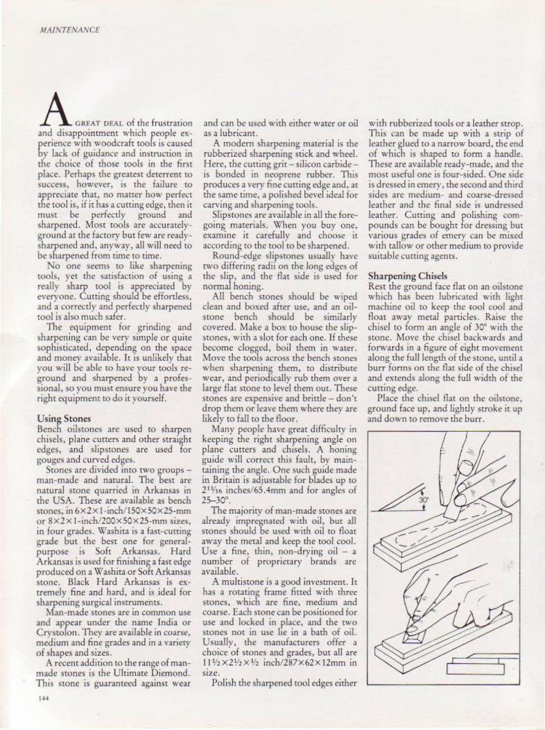
\fA/l\'TF'I/ANCL
A GREAT DEAL of the fmSt"t;o, and disappointment which people experience with woodcraft tools is caused by lack of guidance and instruction in the choice of those tools in the first place. Perhaps the greatest deterrent to success, however, is the failure to appre~:iate that, no matter how perfect the tool is, if it has a cutting edge, then it must be perfectly ground and sharpened. Most tools are accuratelyground at the factory but few are readysharpened and, anyway, all will need to be sharpened from rime to time.
No one seems to like sharpening tools, yet the satisfaction of using a really sharp tool is appreciated by everyone. Cutting should be effortless, and a correctly and perfectly sharpened tool is also much safer.
The equipment for grinding and sharpening can be very simple or quite sophisticated, depending on the space and money available. It is unlikely that you will be able to have your tools reground and sharpened by a professional, so you must ensure you have the right equipment to do it yourself.
Using Stones Bench oilstones are used to sharpen chisels, plane cutters and other straight edges, and slipsroncs are used for gouges and curved edges.
Stones are divided into two groups man-made and natural. The best are natural stone quarried in Arkansas in rhe USA. These are available a!> bench stones, in 6x2xl-inch/150X50X25-mm or 8X2X l-inchi200X50X25-mm sizes, in four grades. Washita is a fast-cutting grade but the best one for generalpurpose is Soft Arkansas. Hard Arkansas is used for finishing a fast edge produced on a Washita or Soft Arkansas stone. Black Hard Arkansas is extremely fine and hard, and is ideal for sharpening surgical instrumentS.
Man-made stones are in common use and appear under the name India or Crystelon. They are available in coarse, medium and fine grades and in a variety of shapes and sizes.
A recent addition to the range of manmade stones is the Ultimate Diemond. This stone is guaranteed against wear
144
and can be used with either water or oil as a lubricant.
A modem sharpening material is the rubberized sharpening stick and wheel. Here, the cutting grit- silicon carbideis bonded in neoprene rubber. Thi~ produces a very fine cutting edge and, at the same time, a polished bevel ideal for carving and sharpening tools.
Slipstones arc available in all the foregoing materials. When you buy one, examine it carefully and choose it according to the tool to be sharpened.
Round-edge slipstoncs usually have two differing radii on the long edges of the slip, and the flat side is used for normal honing.
All bench stones should be wiped clean and boxed after use, and an oilstone bench ~hould be similarly covered. Make a box to house the slipstones, with a slot for each one. If these become clogged, boil them in water. Move the tools across the bench stones when sharpening them, to distribute wear, and periodically rub them over a large flat stone to level them out. These stones are expensive and brittle- don't drop them or leave them where they are likely to fall to the floor.
Many people have great difficulty in keeping the right sharpening angle on plane cutters and chisels. A honing guide will correct this fault, by mainraining the angle. One such guide made in Britain is adjustable for blades up to 21 Vt6 inches/65 .4mm and for angles of 2S-30°.
The majority of man-made stones are already impreonated with oil, but all stones should be used with oil ro float away the metal and keep rhe tool cool. Use a fine, thin, non-drying oil - a number of proprietary brands are available.
A multistone is a good investment. It has a rotating frame fitted with three stones, which are fine, medium and coarse. Each stone can be positioned for use and locked in place, and the two stones not in usc lte in a bath of oil. Usually, the manufacturers offer a choice of stones and grades, but all are 11Y2X21/2X 1/2 inch/287X62X12rnm in SIZe.
Polish the sharpened tool edges either
with rubberized tools or a leather strop. This can be made up with a strip of leather glued to a narrow board, the end of which is shaped to form a handle. These are available ready-made, and the most useful one is four-sided. One side is drc~sed in cmel), the second and third sides arc medium- and coarse-dressed leather and the final side is undressed leather. Cutting and polishing compounds can be bought for dressing but various grades of emery can be mixed with tallow or other medium to provide suitable cutting agents.
Sharpening Chisels Rest the ground face flat on an oilstone which has been lubricated with light machine oil to keep the tool cool and float away metal particles. Raise the chisel to form an angle of 30° with rhe scone. Move the chisel backwards and forwards in a figure of eight movement along the full length of the stone, until a burr forms on the flat side of the chisel and extends along the full width of the cutting edge.
Place the chisel flat on the oilstone, ground face up, and Lightly stroke it up and down to remove the burr.
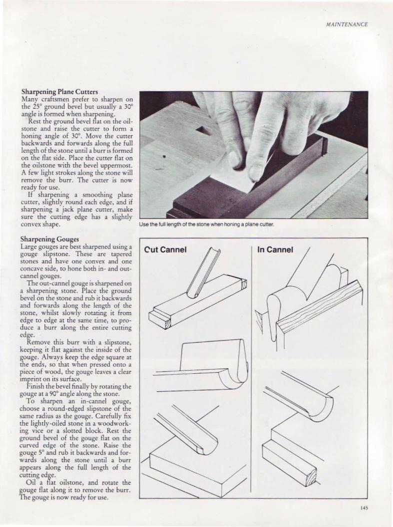
Sharpening Plane C utters Many craftsmen prefer to sharpen on the 25° ground bevel but usually a 30° angle is formed when sharpening.
Rest the ground bevel flat on the oilstone and raise the cutter to form a honing angle of 30°. Move the cutter backwards and forwards along the fu!J length of the stone until a burr is formed on the flat side. Place the cutter flat on the oilstone with the bevel uppermost. A few light strokes along the stone will remove the burr. The curter is now ready for use.
If sharpening a smoothing plane cutter, slightly round each edge, and if sharpening a jack plane cutter, make sure the cutting edge bas a slightly convex shape. Use the full length otthestone when honing a plane cutter.
Sharpening Gouges Large gouges are best sharpened using a gouge slipstone. These are tapered stones and have one convex and one concave side, to hone both in- and outcannel gouges.
The out-cannel gouge is sharpened on a sharpening stone. Place the ground bevel on the stone and rub it backwards and forwards along the length of the stone, whilst slowly rotating it from edge to edge at the same time, to produce a burr along the entire cutting edge.
Remove this burr with a slipstone, keeping it flat against the inside of the gouge. Always keep the edge sq uare at the ends, so that when pressed onto a piece of wood, the gouge leaves a clear tmprint on its surface.
Finish the bevel finaJly by rotating the gouge at a 90° angle along the sLone.
To sharpen an in-cannel gouge, choose a round-edged slipstone of the same radius as the gouge. Carefully fix the lightly-oiled stone in a woodworking vice or a slotted block. Rest the ground bevel of the gouge flat on the curved edge of the stone. Raise the gouge 5° and rub it backwards and forwards along the stone until a burr appears along the full length of the cutting edge.
Oil a flat oilstone, and rotate the gouge flat along it to remove the burr. The gouge is now ready for use.
Cut Cannel In Cannel
MAINTENAl\CE
145
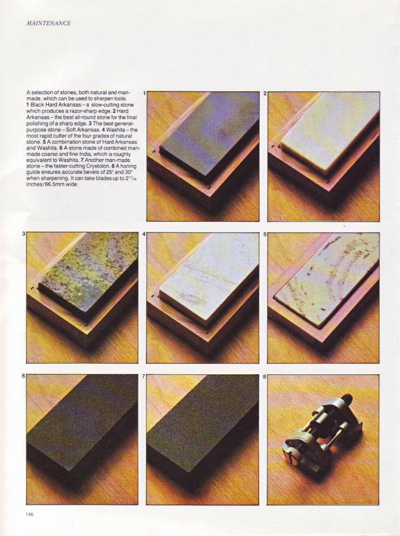
MAINTENANCE
A selection of stones, both natural and manmade, which can be used to sharpen tools. 1 Black Hard Arkansas- a slow-cutting stone which produces a razor-sharp edge. 2 Hard Arkansas - the best all-round stone for the final polishing of a sharp edge. 3 The best generalpurpose stone- Soft Arkansas. 4 Washita - the most rapid cutter of the four grades of natural stone. 5 A combination stone of Hard Arkansas and Washita. 6 A stone made of combined manmade coarse and fine India, which is roughly equivalent to Washita. 7 Another man-made stone - the faster-cutting Crystolon. 8 A honing guide ensures accurate bevels of 2s· and 30• when sharpening. It can take blades up to 2"1,. inches/66.5mm wide.
H6

If a shpstone is too sharp when new, rub a lead pencil into it to take off the edge of the grit. 1 Four shpstones- Hard Arkansas, Soft Arkansas, Washita and Crystolon. 2 A Hard Arkansas grooved stone. very useful for honing small. steep gouges. 3 A Hard Arkansas knife f1le and a Hard Arkansas tnangular file. 4 A med1um lnd1a knife file and a line India auger stone 5 A set of four Hard Arkansas stones m a vanety of shapes. 6 Hard Arkansas file set w1th square, knife, round, d1amond and triangular stones. 7 A fine India round-edge cone gouge slipstone. 8 An ax sharpenmg stone of Hard Crystolon on one side and Med1um Crystolon on the other.
~IA/NTI:.'a\'A ~'C£
Jr---------------------------, 4r---------------------------~ sr---------------------------~
147
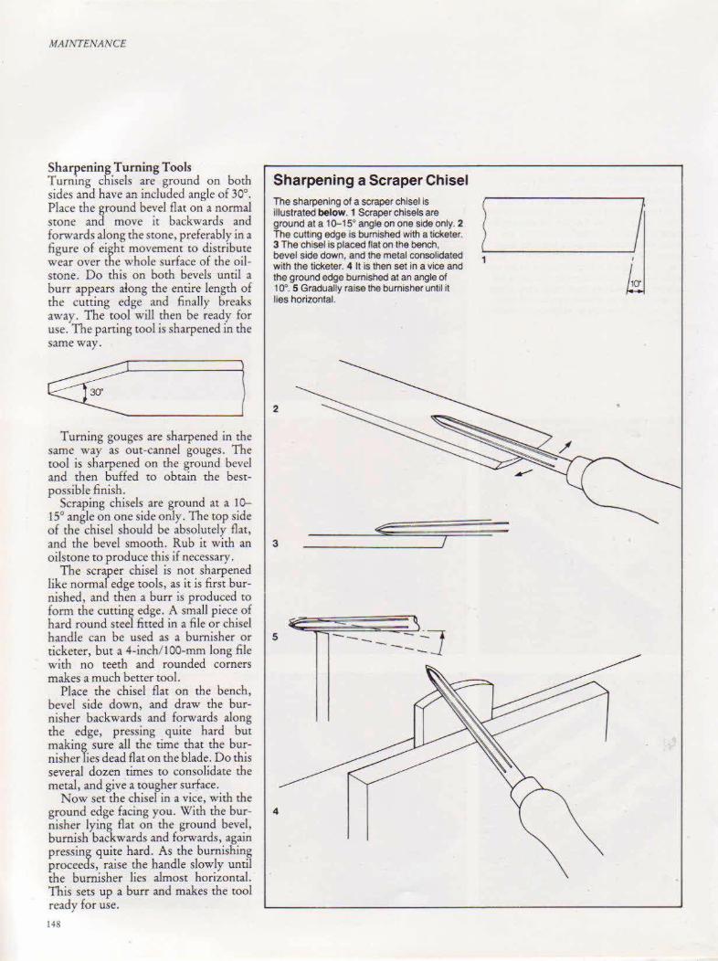
MAINTENANCE
Sharpening Turning Tools Turning chisels are ground on both sides and have an included angle of 30°. Place the ground bevel flat on a normal Stone and move it backwards and forwards along the stone, preferably in a figure of eight movement to distribute wear over the whole surface of the oilstone. Do this on both bevels until a burr appears along the entire length of the cutting edge and finally breaks away. The tool will then be ready for use. The parting tool is sharpened in the same way.
Turning gouges are sharpened in the same way as out-cannel gouges. The tool is sharpened on the ground bevel and then buffed to obtain the bestpossible finish.
Scraping chisels are ground at a 10-150 angle on one side only. The top side of the chisel should be absolutely flat,
Sharpening a Scraper Chisel
The sharpening of a scraper chisel is l ~ illustrated below. 1 Scraper chisels are ground at a 1 0-15" angle on one side only. 2 The cutting edge is burnished with a ticketer. 3 The chisel is placed flat on the bench, _ . bevel side down, and the metal consolidated ...._ _________ __)
with the ticketer. 4 It is then set in a vice and the ground edge burnished at an angle of 1 o•. 5 Gradually raise the burnisher until it lies horizontal.
2
and the bevel smooth. Rub it with an 3 ojlstone to produce this if necessary.
The scraper chisel is not sharpened like normal edge tools, as it is first burrushed, and then a burr is produced to form the cutting edge. A small piece of hard round steel fitted in a file or chisel handle can be used as a burnisher or 5 ticketer, but a 4-inch/ 100-mm long file with no teeth and rounded corners makes a much better tool.
Place the chisel flat on the bench, bevel side down, and draw the burnisher backwards and forwards along the edge, pressing quite hard but making sure all the time that the burrusher lies dead flat on the blade. Do this several dozen times to consolidate the metal, and give a tougher surface.
Now set the chisel in a vice, with the ground edge facing you. With the bur- 4 nisher lying flat on the ground bevel, burnish backwards and forwards, again pressing quite hard. As the burnishing proceeds, raise the handle slowly until the burnisher lies almost horizontal. This sets up a burr and makes the tool ready for use.
J.l8
--- -...:..] -----
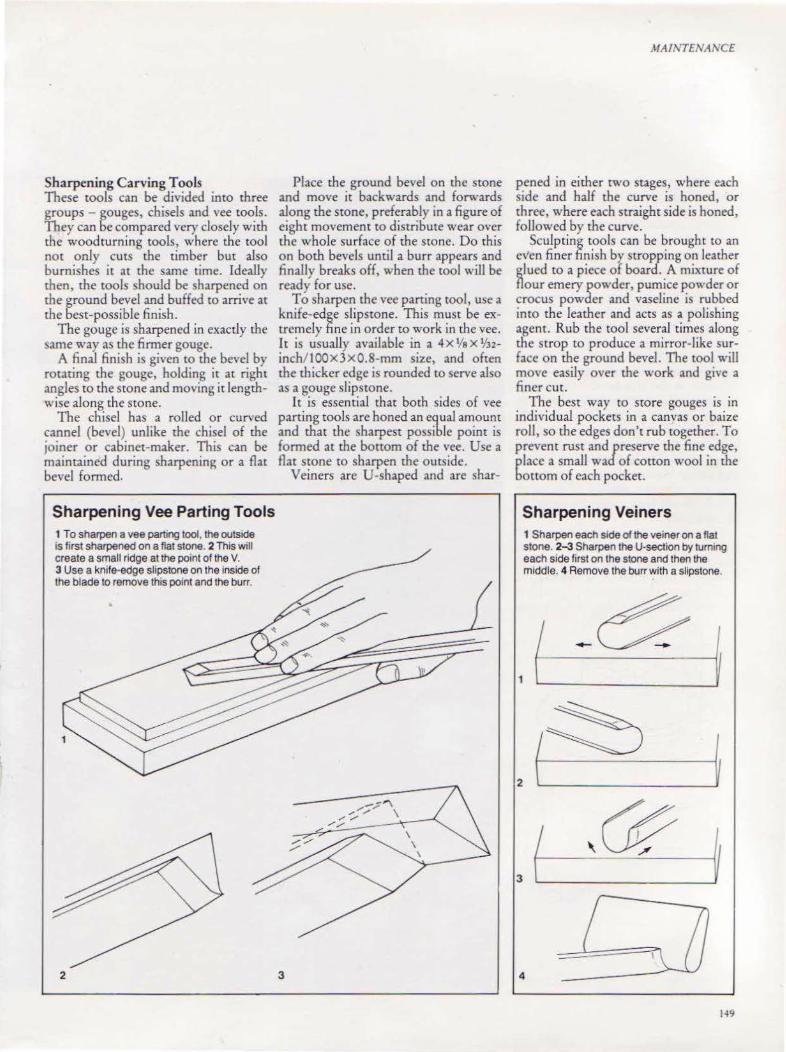
Sharpening Carving Tools These tools can be divided into three groups - gouges, chisels and vee tools. They can be compared very closely with the woodturning tools, where the tool not only cuts the timber but also burnishes it at the same time. Ideally then, the tools should be sharpened on the ground bevel and buffed to arrive at the best-possible finish.
The gouge is sharpened in exactly the same way as the firmer gouge.
A final finish is given to the bevel by rotating the gouge, holding it at right angles to the stone and moving it lengthwise along the stone.
The chisel has a rolled or curved cannel (bevel) unlike the chisel of the joiner or cabinet-maker. This can be maintained during sharpening or a flat bevel formed.
Sharpening Vee Parting Tools 1 To sharpen a vee parting tool, the outside IS first sharpened on a flat stone. 2 This will create a small ridge at the point of the V. 3 Use a knife-edge slipstone on the Inside of the bJade to remove this point and the burr.
2
Place the ground bevel on the stone and move it backwards and forwards along the stone, preferably in a figure of eight movement to diStribute wear over the whole surface of the stone. Do this on both bevels until a burr appears and finally breaks off, when the tool will be ready for use.
To sharpen the vee parting tool, use a knife-edge slipstone. This must be extremely fine in order to work in the vee. It is usually available in a 4 X Va X lf32-inch/100X3X0.8-mm size, and often the thicker edge is rounded to serve aJso as a gouge slipstone.
It is essential that both sides of vee parting tools are honed an equaJ amount and that the sharpest possible point is formed at the bottom of the vee. Use a flat stone to sharpen the outside.
Veiners are U-shaped and are shar-
MAINTENAl\CE
pened in either two stages, where each side and haJf the curve is honed, or three, where each straight side is honed, followed by the curve.
Sculpting tools can he brought to an even finer finish by stropping on leather glued to a piece of board. A mixture of flour emery powder, pumice powder or crocus powder and vaseline is rubbed into the leather and acts as a polishing agent. Rub the tool several times aJong the s trop to produce a mirror- like surface on the ground bevel. The tool will move easily over the work and give a finer cut.
The best way to store gouges is in individual pockets in a canvas or baize roll, so the edges don't rub together. To prevent rust and/reserve the fine edge, place a small wa of cotton wool in the bottom of each pocket.
Sharpening Veiners 1 Sharpen each side of the veiner on a flat stone. 2-3 Sharpen the U-section by turnu19 each side first on the stone and then the middle. 4 Remove the burr with a sllpstone.
149

MA/1\'TENANC£
Grinding Many woodcrafrsmen prefer to hand their grinding problems over to a professional, particularly when faced with the cost of grinding equipment. Obviously, it is economical tO buy this equipment only if its use justifies the COSt.
The earliest grindstones were made of cutting stone, with a fairly soft, open texture. Water was used to cool down the stone.
The us·e of water wet stone has been reintroduced, on both sides of the Atlantic, as the Sharpenset. Unlike rhe traditional wet stone, it runs in the horizontal, with a constant jet of water supplied from a small electric pump. It has a fine cutting wheel to which can be fitted a grinding jig for holding jointer and planer blades. This is a completely safe and efficient method of grinding which should have particular appeal to the home craftsman.
The straight dry grinder is powered by electricity, and has one or two wheels, which are either fine or coarse. Take great care when using this tool , as it revolves at a high speed and produces so much heat that it can ruin the tool
ISO
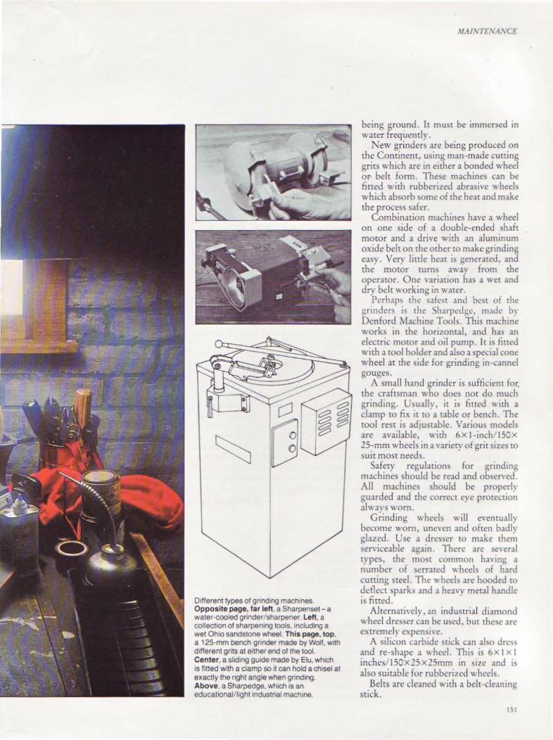
01Herent types of gnnd1ng machines. Opposite page, far lett, a Sharpenset- a water-cooled grinder/sh&rpener. Left, a collection of sharpening tools, 1ncluding a wet Oh1o sandstone wheel This page, top, a 125-mm bench gnnder made by Wolf, w1th d1Herent grits at Mher end of the tool. Center, a sliding gUide made by Elu, wh1ch IS fitted with a clamp so it can hold a chisel at exactly the right angle when grinding. Above, a Sharpedge, wh1ch 1s an educational/light mdustnal machine.
.\fA/\ JI.\'A.\'C£
being ground. It must be immersed in water frequently.
New grinders arc being produced on the Continent, using man-made cutting grits which are in either a bonded wheel or belt form. These machines can be fined with rubberized abrasive "heels '' hich absorb some of the heat and make the process safer.
Combination machines have a wheel on one side of a double-ended shaft motor and a drive with an aluminum oxide belt on the other to make grinding caS). Very little heat is generated, and the motor turn a\\ ay from the operator. One variation has a wet and dry belt working in water.
Perhaps the s,tfcst and best of the ~rinders is the Sh.trpedge, made b)· Dcnford Machine Tools. This machine works in the horiLOntal, and ha~ an electric motor and oil pump. It is lined with a tool holder and also a special cone wheel at the side for grinding in-cannel gouges.
A small hand ~rinder is sufficient for. the craftsman who docs not do much grinding. Usuallv, it is fim:d "1th a clamp to fix it to a table or bench. The tOol rest is adJustable. Variou) models are available, vmh 6X l-inch I SOX 25-mm wheels in a ''ariety of grit sizes to
suit most needs. Safety regulations for grinding
machines ~hould be read and ob'>crved. All machines should be properlr guarded and the correct eye prote~tion always worn.
Grinding wheels will eventually become worn, uneven and often badlv glazed. Use a dresser to make ther~ serviceable ,\gain. There are several types, the most common ha' ing a number of serrated "·heels of hard cutting steel. The wheels arc hooded to deflect sparks and a heavy metal handle is fined.
Alternatively, an industrial diamond wheel dresser can be used, but these are extremely cxpcnsi\e.
A silicon carbide stick can al o drc'!> and re-shape a wheel. This is 6X I x I inches/ 150X25X25mm in size and is also suitable for rubberized wheels.
Belts are cleaned with a belt-cleaning stick.
bl

MAINTENANCF
Sharpening Scrapers Use a burnisher or ticketer to sharpen bench, cabinet and woodturning scrapers. All these tools have a fine steel edge which has to be turned over along its length by a burni!>hcr, to form a burr. Several styles are available, with tapered blades in triangular, round or oval section. They are all fitted with wooden handles.
Bench scrapers are also sharpened on a wheel burnisher. This has a beech body fitted with an accuratelymachined guide, and a steel disk mounted centrally in the body burnishes a perfect cutting hook.
When it is new, a cabinet scraper will be square and straight-edged, but after prolonged use it will need to be reshaped. To do this, place it in a vice and straighten the edge with a smooth file. You can also rub the scraper on an oilstone to produce the same effect.
The edge will now be straight and fairly sharp and it must be burnished. The burnisher should be steel, harder than the cutter, and fitted with a handle for safety.
Place the cutter flat on the bench and draw the burnisher backwards and forwards across it about twenty times, pressing quite hard but always keeping the burnisher dead flat on the blade. This consolidates the metal.
Now clamp the cutter in a vice and,
Sharpening Bench Scrapers
--
with the burnisher lying along the top of the cutter, draw it backwards and forwards, pressing quite hard. Gradually lower the handle of the burnisher so that it makes an angle of IS0 with the horizontal. This will turn the edge over to form the cutting burr. Repeat this on the opposite side of the cutter.
The cutter of a double-handed scraper is removed from the tool and beveled on both long edges. New cutters are supplied ground at 4S0 by the factory but they must be sharpened carefully before use. This i'S best carried out on a fine or medium stone maintaining the same angle. Use a light machine oil on the oilstone and remember to leave the stone clean and dry after use.
When sharpening cutters, always: 1 Keep the burnisher lightly oiled to
reta~n its high polish and to prevent rusung.
2 Draw the scraper blade back into the double-handed scraper before putting it away lightly oiled.
To sharpen the cutter, rest the ground be\'el flat on the stone. Keeping the cutter at this angle, move it backwards and fonvards across the stone. As the cutter becomes sharp, a slight burr will appear on the flat face and when this extends along the full width, place the cutter flat on the oilstone with the bevel uppermost. A few light strokes up and down the stone will remove the burr.
Always take great care that the back of the cutter lies flat on the oilstone, as any lift will round the back of the cutter and make it useless. It is an advantage if the comers of the blade are very slightly rounded.
To burnish the cutter, place it flat on the bench, bevel side downwards and, using a burnisher of the correct steel, draw it along the edge backwards and forwards about thirty times, pressing quite hard but always checking that the burnisher lies flat on the blade. On no account must the edge be turned over.
Now, set up the cutter in a vice with the ground edge facing you and, with the burnisher lying on the 4S0 bevel, and pressing quite hard, burnish forwards and backwards. As the burnishing proceeds, gradually raise the handle until the burnisher makes an angle of IS0
with the horizontal. This may take up to 36 strokes, depending upon the pressure of the burnisher. A lubricant will make this easier. The edge will now have a definite burr and is ready for usc.
Tore-sharpen the cutter, remove the burr from the flat side of the cutter either on an oilstone or w~th a dead smooth file, taking care not to create a bevel. If necessary, rub the cutter on the edge of the oilstone to straighten it.
File or grind the edge tO 45° if necessary, and then sharpen as for a new blade.
Sharpening Cabinet Scrapers
The SC(aper is burn1shed, w1th the tJcketer held horizontally at 90~
The scraper IS
burnished to consolidate the metal.
~-::::._-_,'fl. ~1J.~
152
Clamp the scraper 1n a vice and burnish the cutting edge, starting horizontally and gradually lowering the ticketer until it forms an angle of 15~
It is then clamped in a vice and burnished at a 45" angle, gradually rising to a 15• angle.
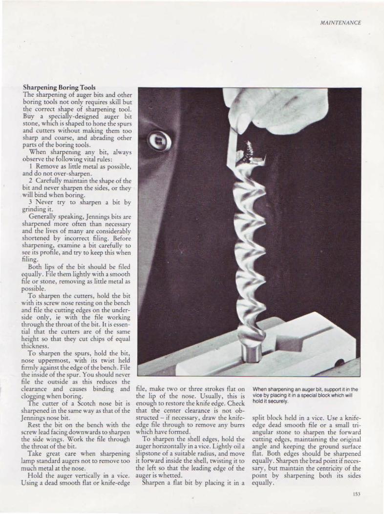
Sharpening Boring Tools The sharpening of auger bits and other boring tools not only requires skill but the correct shape of sharpening tool. Buy a specially-designed auger bit stone, which is shaped to hone the spurs and cutters without making them too sharp and coarse, and abrading other parts of the boring tools.
When sharpening any bit, always observe the following vital rules:
1 Remove as little metal as possible, and do not over-sharpen.
2 Carefully maintain the shape of rhc bit and never sharpen the sides, or rhey will bind when boring.
3 Never try to sharpen a bit by grinding it.
GeneraJly speaking, Jennings bits are harpened more often than necessary
and the lives of many are considerably shortened by incorrect filing. Before sharpening, examine a bit carefully to see its profile, and try to keep this when filing.
Both lips of the bit should be filed equally. File them li~htly with a smooth file or stone, removmg as little metal as possible.
To sharpen the cutters, hold the bit with its screw nose resting on the bench and file the cutting edges on the underside only, ic with the file working through the throat of the bit. lt is essential that the cutters are of the same height so that they cut chips of equal thickness.
To sharpen the spurs, hold the bit, nose uppermost, with its twist held fim1ly against the edge of the bench. File the inside of the spur. You should never file the outside as this reduces the clearance and causes binding and clogging when boring.
The cutter of a Scotch nose bit is sharpened in the same way as that of the Jennings nose bit.
Rest the bit on the bench with the screw lead facing downwards to sharpen the side wings. Work the file through the throat of the bit.
Take great care when sharpening lamp standard augers not to remove too much metal at the nose.
Hold the auger vertically in a vice. Using a dead smooth flat or knife-edge
file, make two or three strokes flat on the lip of the nose. Usually, this is enough to restore the knife edge. Check that the center clearance is not obstructed- if necessary, draw the knifeedge file through to remove any burrs which have formed.
To sharpen the shell edges, hold the auger horizontally in a vice. Lightly oil a slipstone of a suitable radius, and move it forward inside the shell, twisting it to the left so that the leading edge of the auger is whetted.
Sharpen a flat bit by placing it in a
JIAINTI '\AXC£
When sharpentng an auger b1t, support 1t 1n the vice by placing 11 1n a spec1al block wh1ch w111 hold it securely.
split block held in a vice. Use a knifeedge dead smooth file or a small triang\llar stone to sharpen the fonvard cutting edges, maintaining the original angle and keeping the ground surface flat. Both edges should be sharpened equally. Sharpen the brad point if necessary, but maintain the centricity of the point by sharpening both its sides equally.
153
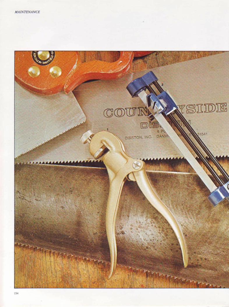
MAINTENANCE
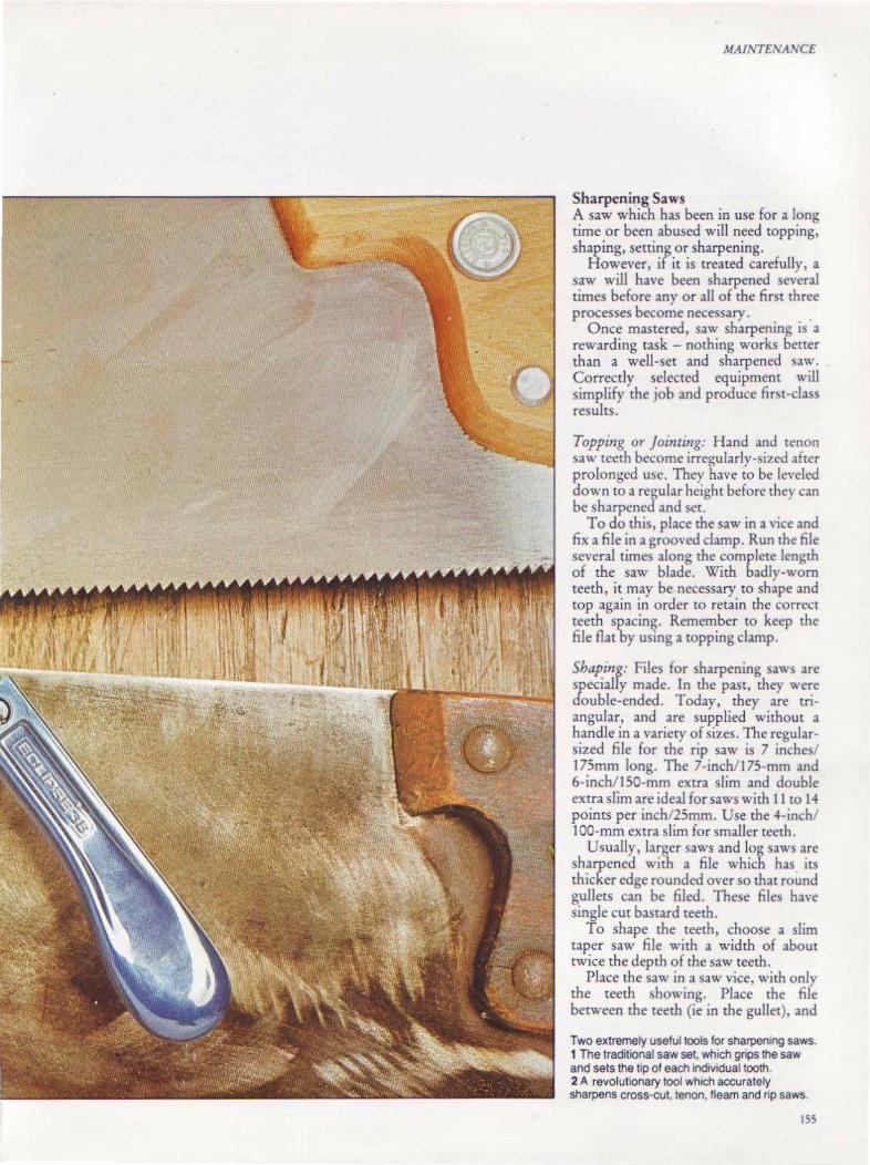
MAINTENANCE
Sharpen ing Saws A saw which has been in use for a long time or been abused will need topping, shaping, setting or sharpening.
However, if it is treated carefully, a saw will have been sharpened several times before any or all of the first three processes become necessary.
Once mastered, saw sharpening is a rewarding task - nothing works better than a well-set and sharpened saw. Correctly selected equipment will simplify the job and produce fim-class results.
Topping or jointing: Hand and tenon saw teeth become irregularly-sized after prolonged use. They have to be leveled down to a regular height before they can be sharpened and set.
To do this, place the saw in a vice and fix a file in a grooved clamp. Run the file several times along the complete length of the saw blade. With badly-worn teeth, it may be necessary to shape and top again in order to retain the correct teeth spacing. Remember to keep the file flat by using a topping clamp.
Shaping: Files for sharpening saws are specially made. In the past, they were double-ended. Today, they are triangular, and are supplied without a handle in a variety of sizes. The regularsized file for the rip saw is 7 inches/ 17Smm long. The 7 -inch/ 1 75-mm and 6-inchlt 50-mm extra slim and double extra slim are ideal for saws with II to 14 points per inchl25rnm. Use the 4-inch/ 100-mm extra slim for smaller teeth.
Usually, larger saws and log saws are sharpened with a file which has its thicker edge rounded over so that round gullets can be filed. These files have single cut bastard teeth.
To shape the teeth, choose a slim taper saw file with a width of about twice the depth of the saw teeth.
Place the saw in a saw vice, with only the teeth showing. Place the file between the teeth (ie in the gullet), and
Two extremely useful tools for sharpening saws. 1 The traditional saw set, which grips the saw and sets the tip of each individual tooth. 2 A revolutionary tool wh1ch accurately sharpens cross-cut, tenon, fleam and rip saws.
155

MAINTENANCE
Topping Before beginning to sharpen a saw, it is necessary to support it. The simplest way is to hold it between two strips of wood clamped in a vice, as shown below.
If you don't have a purpose-built saw jointer, top a saw by cutting a groove in a piece of wood and hold a file in it with a narrow· wedge.
press down firmly with the left hand so that the file takes up the correct pitch pf the teeth. Draw it straight across the saw at right angles tO the teeth. File each gullet carefully, ensuring that each tooth when filed is of the corre.ct shape and height. Any flattening caused by topping wi!J be removed.
Setting: Before any saw can work correctly, its teeth must be set alternately to the left and right. This must be done accurately, so that the points of the saw cut a kerf slightly wider than the thickness of the blade, and the saw
156
Saw teeth will become irregular in height if they are badly shaped. It will then be necessary to bring them all to the same level.
moves easily through the wood. A saw set will perform this task. It is
fitted with a hardened steel anvil and a micro-setting screw which controls the distance at which each tooth can be set. Its trigger-type action makes it easy to use, and means it can be used on hand and circular saws.
Buy a plicr-type of saw set if you will only use it occasionally. Adjust the pliers to give the correct set, and place them over the tOOth. When you squeeze the handles, the plunger will push the tooth over against an anvil. Set alternate teeth in this way, then reverse the saw
Shaping Saw teeth are shaped with a triangular file, held at go• to the saw blade.
Rip saw teeth are pitched at an angle of a• from the vertical, as shown above. Cross cut teeth, below, are pitched at 15• to the vertical.
' \ /~I.·.
' \ /~ 45!..._J_..j . \ I .
600~ \
and set the alternate teeth which you ignored the first time.
Teeth set by hand may have slight irregularities which must be removed by side-dressing. This is done by running a slipstOnc lightly along the sides of the teeth with the saw held flat on the bench.
Sharpening: Use a file to sharpen cross cut saws. Position the file to work on the front edge of the first tooth set towards you.
The file will also be working on the back edge of the left tooth, which is, of

Setting The pher-type of saw set should be adjusted to the number of points per inch/25mm of the saw whiCh IS to be set. The teeth are set alternately along one side of the saw. wh1ch IS
then reversed so that the other side can be set. -------~--
----
As shown above, only the top half of the teeth are set. After this process has been completed, the saw must be side-dressed with a slipstone, to remove any burrs which might have formed on the teeth, balow.
course, leaning away from you. Move the file handle over to the left until it makes an angle of 60° with the saw. Give each alternate tooth several strokes with the file kept at this angle. The front edge of the tooth leaning towards you is then filed each time. Continue filing to the en~ of the saw, reverse it and repeat the acuon.
Rip saw teeth are sharpened in the same way as cross cut saw teeth, but the file must be held at 90° across the saw. File each alternate tooth on one side and then file each alternate tooth on the reverse side.
L _~ J
A recent British-designed saw sharpener has two guide bars which keep the file in its correct position in relation to the saw blade. lt can be used on saws with between 41/2 and 15 points per i~ch/25mm and is suitable for cross cut, np or tenon saws.
After sharpening, lightly side-dress the saw with an oil~tone to remove any burrs.
Tenon and dovetail saws are sharpened in the same way as cross cut saws, but greater care is needed to maintain the correct tooth size and set. Saws with very small teeth may have to be returned
i1AINT£NA !\ CF
Sharpening The rip saw is sharpened at an angle of goo to the blade and the cross cut saw at60".
7~ /\\/V\/\1\AA
A few lines drawn on the bench at the reqUired angle will help the beginner keep to a constant bevel when sharpening.
to the manufacturers for settmg and sharpening.
Circular saw sharpeners have to true the periphery of the saw as well as set the teeth. One such tool accepts blades of between 6-T2 inches/15~300mm in diameter, and its cone center takes 1 '2-'l's -inch/12-21-mm holes. Lock the circ~lar saw blade before filing and semng.
Several circular saw sharpeners also file the teeth perfectly. The simplest versions clip onto the edge of a bench. They arc adjusted slightly to align the file and control the filing.
157

158

CHAPTER THIRTEEN
To fit hinges, brackets and other metal or plastic fittings, fixing
tools will be needed; they must be chosen carefully
before buying.
159

FIXI'VG TOOLS
M ANY •·ooowoRRJNG projec" need hinges, bracke~ and other metal or plastic fittings before they are finished. You will need ro buy fixing tools to do these jobs, and like any other woodcraft toob, they must be chosen carefully before buying.
This group of tools can be divided rough) y into three categories- those for hammering, those for screwing, and the actual nails, screws or other fixing components.
Hammers Of these tool!., the hammer is the most abused and the one most likely to be selected incorrectlY. As with chisels, there is a hamme; for every job and there are as many badly-made hammers as there are good one:.. The best hammers have carefully-selected wooden shafts, preferably of ash or hickory. These are oil-shrunk at the head to reduce shrinkage. All heads arc doublewedged for security - at least one of the wedges being metal.
A whole new range of hammers '' ith <;ted or glass fiber shafts has been introduced in recent years. These have very long lives but many woodworkers prefer the feel of wood. and object to the extra springiness of steel.
The hammer is used for driving in nails and pins to hold material together, to drive in wedges and, in conjunction with a splitproof chisel, adds weight when cutting morrice and other joints. You will need rwo types of basic hammer- the claw, which removes nails from wood, and the cross-peen, used in fine work.
The Warrington hammer has long been recognized as the best style of hammer for the craftsman. It has a forged head, carefully ground with a flat peen at the opposite end of the poll for starting nails. h is available in six different weights, although the~e are referred to by number.
160
o 00 6 ounces 168g 0 8 ounces/224g I 10 ounces/280g 2 12 ounces/336g 3 14 ounces/392g 4 16 ounces/450g
The pin hammer is light, with the same-shaped head as the Warrington pattern. It only weighs 3112 ounces/98g, with a much longer and thinner handle. Use it for light work - particularly driving in panel pim, glazier's pins and tiny brads.
The adz eye claw hammer is used for heavy work, for extracting nails and breaking apart cases and packages. This wol takes its name from the rectangularshaped eye, which is used in the adz. It is available with rwo different types of claw - one has a distinct curve when looked at in elevation, and the other is straighter and used as a lever to open crates. This is often called a rippingstvle hammer.
'The claw of any hammer must always be correctly forged to grip the nail. In fact, the best way to test a claw is to drive a 4-inch/ 100-mm round nail completely through a ~tout plank, and then remove it by drawing it through, with the head last. When it is stood on its head on a bench, a well-balanced claw hammer will rest on the claw with the shaft at a 45° angle, leaning wwards you. This hammer is available in four weights.
No 1 !3 ounces/364g 2 16 ounces/450g 3 20 ounces/560g 4 24 0unces/6l2g
Steel-shafted claw hammers are practically indestructible and are sold in similar weighrs w the wood-shafted type. Some hammers have leather wrdpped around the handle, while others have a rubber or plastic sleeve fixed with an adhesive.
When doin~ craft work, nails and pins have to be dnven without the indentation of the hammer head showing. There are a number of hammers with removable and replaceable faces ideal for this particular work.
The best-known of these is the Thor, which has a diecast aluminum head to \\·hich can be screwed rwo sizes of faces - 1 lfs inch/3Smm and 13/4 inch/43mm, made either of rubber or nylon. The head is filled with lead shot to add weight and reduce bounce. It has a metal or wooden shaft.
You can use a pin push, or brad pusher, instead of the hammer when driving panel pins and small headless steel nails. This tool has a small barrel \\·ith a magnetized and sprung plunger. The pin is dropped into the barrel and held by the magnet. Push on the pla~uc or .wooden handle and the plunger pushes the fin into the wood.
This too is particularly useful when pinning hardboard, as the tough outer skin tends to cause the pin to bend when a hammer is used, but the barrel of the pin J?U~h supportS the pin dunng mseruon.
The pin push or brad pusher holds p1ns or small na1ls magnellcally in the barrel Pressure on lhe handle pushes the p1n 1nto lhe wood.
Opposite, top to bottom, the cross-peen or Warnngton hammer has a Hal peen for start1ng nails. The p1n hammer is used for driv1ng pms or tacks. Claw hammers have either a curved claw for gripping nails, or a straight or ripping claw for levering open crales. The Thor hammer has interchangeable soft heads to drive na11s and pins without indenting the work.
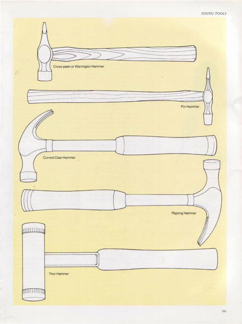
FIXING TOOLS
Cross-peen or Warrington Hammer
------ --------------- ----· --------
P1n Hammer
Curved Claw Hammer
Ripping Hammer
Thor Hammer
161
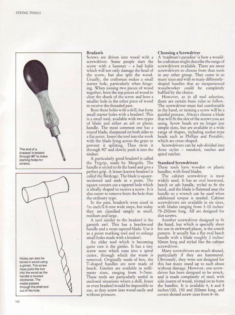
FIXING TOOLS
The end of a bradawl is twisted through 90° to make starting holes for screws.
Holes can also be bored in wood using a gimlet. The screw nose pulls the tool into the wood as the handle is twisted clockwise. The waste passes through the shell and out of the hole.
162
Bradawls Screws are driven into wood with a screwdriver. Some people start the screw with a hammer - a bad habit which will not only damage the head of the screw, but also split the wood. Usuall y, the craftsman makes a small starter hole, particularly when hingcing. When joining· rwo pieces of wood together, bore the top pieces of wood to clear the shank of the screw and bore a smaller hole in the other piece of wood to receive the threaded part.
Bore these holes with a drill, but form small starter holes with a bradawl. This is a small tool, available with rwo types of blade and either an ash or plasric handle. The most common one has a round blade, sharpened on both sides ro a flat point. Insert the tOol into the work wirh the blade lying across the grain to prevenr it splitting. Then rwisr it through 90° and slowly push it inro the timber.
A particularly good bradawl is called the Trigrip, made by Margolis. The handle is sty led to fit the hand and give a perfect grip. A lesser-known bradawl is called the Birdcage. The blade is squaresectioned and ends in a point. The square corners cur a tapered hole which is ideally shaped to receive a screw. 1t is also easier to remove from the hole rhan the ordinary type.
In the past, bradawls were sized in 1/32-inch/0.8-mm wide steps, but today they are classified simply as small, medium and large.
A tool similar to the bradawl is 'the garnish awl. This has a beechwood handle and a stout tapered blade. Use it as a roint marking tool and tO enlarge smaL holes made with a bradawl.
An older tool which is becoming quite rare is the gimlet. It has a r1ny screw nose which runs into a spiral cutter, through which the waste is removed . Originally made of box, the T-shaped handles are now made of beech. Gimlets are available in miUimeter s izes, ranging from 3-7mm. These rools are particularly useful in enclosed situations where a drill, brace or even bradawl would be impossible to
use, as they screw into wood easily and without pressure.
Choosing a Screwdriver A 'madman's paradise' is how a wouldbe craftsman might describe the range of screwdrivers available. There are more screwdrivers to choose from than tools in any other group. They come in so many sizes and with so many differentlyshaped handles that an inexperienced woodworker could be completely baffled by the choice.
However, as in all tool selection, there are certain basic rules tO follow. The screwdriver must feel comfortable in the hand, or turning a screw will be a painful process. Always choose a blade that will fit the slot of the screws you are using. Screw heads are no longer just simple slots, but are available in a wide . range of shapes, includi ng socket-type heads such as Phillips and Pozidriv, which are cross-shaped.
Screwdrivers can be sub-divided into three styles - standard, ratchet and spiral ratchet.
Standard Screwdrivers These rools have wooden or plastic handles, with fixed blades.
The cabinet screwdriver is most widely used. It has an oval boxwood, beech or ash handle, styled to fit the hand, and the blade is flattened near the handle so a wrench can be used when additional torque is needed. Cabinet screwdrivers are available in six sizes, with blades ranging from 3- 10 inches/ 75-250mm long. All arc designed for slot screws.
Another screwdriver designed to fir the hand, but which is specially short for use in awkward places, is the crutch pattern. lt usually has a flat oval beech handle with a blade roughly 2 inches/ SOmm long and styled like the cabinet screwdriver.
Many screwdrivers arc much abused, particuJarly if they are hammered. Obviously, they were not designed for this but many stand up to such abuse without damage. However, one screwdriver has been designed to be struck, and is made completely of steel, with side inserts of wood, riveted on tO fom1 the handles. It is available 4, 6 and 8 inchcs/JOO, 150 and 200mm long, and covers slotted screw sizes from 8-16.
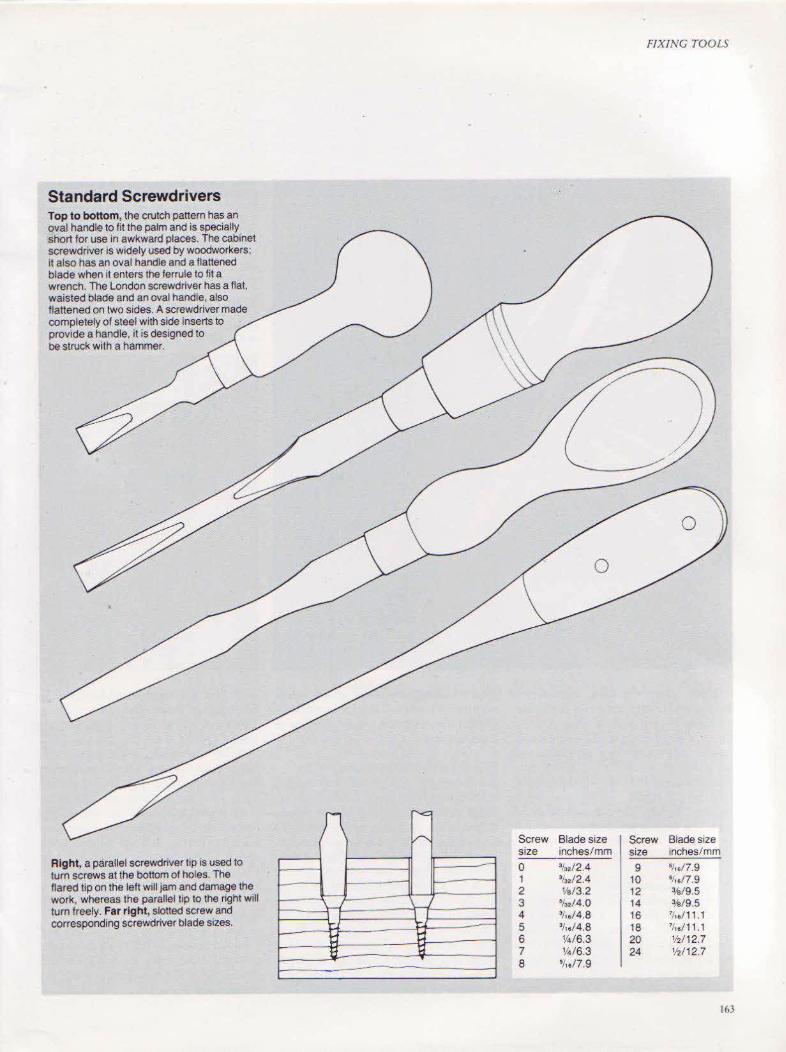
Standard Screwdrivers Top to bottom, the crutch pattern has an oval handle to fit the palm and is specially short for use in awkward places. The cabinet screwdriver is widely used by woodworkers; it also has an oval handle and a flattened blade when it enters the ferrule to fit a wrench. The London screwdriver has a flat, waisted blade and an oval handle, also flattened on two sides. A screwdriver made completely of steel with side inserts to provide a handle, it is designed to be struck with a hammer.
Right, a parallel screwdriver tip is used to turn screws at the bottom of holes. The flared tip on the left will jam and damage the work, whereas the parallel t1p to the right will turn freely. Far right, slotted screw and corresponding screwdriver blade sizes.
Screw Blade size size inches/mm
0 %.12.4 1 •/,./2.4 2 Ya/3.2 3 •t •• /4.0 4 3/to/4.8 5 3! •• /4 .8 6 114/6.3 7 %/6.3 8 •! •• 17.9
FIXING TOOLS
Screw Blade size size inches/mm
9 •t .. /7.9 10 •t •• /7.9 12 %/9.5 14 %/9.5 16 '/,./11.1 18 '/,./11.1 20 1hl12.7 24 Y2/1 2.1
163

FIXING TOOLS
Most plastic-handled screwdrivers have round blades and come in a variety of blade lengths and tip sizes. Choo;e them with great care. The size of the handle must not onlr be compatible with the length of the blade, but must also comfortably fit the hand to prevent blistering, while giving maximum turning facility. Avoid molded octagonal or hexagonal handles which gi,·e insufficient torque and are extremely uncomfortable co use.
Ratchet Screwdrivers These invaluable tools were designed to turn screws easily by a simple twist of the hand. They have a simple sliding device which allows the screwdriver to be set in clockwise and anticlockwise directions, and in a fixed position. The better types also have a knurled finger
164
grip which greatly helps in the initial starting of screws. They are available in several sizes and have slotted, Phillips or Pozidriv tips.
Spiral Ratchet Screwdrivers An extended design of the ratchet screwdriver is the ~piral ratchet- sometimes described as the push, or pump, screwdriver. A ratchet device similar to that of the straight ratchet gives clockwise, amidockwise and fixed movement of the spiral ratchet spindle through a barrel \vhich houses a rcrurn spring, aLlowing the screwdriver to be pushed. It can also be locked in the fully-open position to give a fixedaction screwdriver, providing extended reach and torque. A number of designs have interchangeable bits to cover the variation in types of screw heads. Tiny
There is a tremendous variety in the destgn ol handles for screwdnvers. Left, square bar, flared tip screwdrivers, with heavy-(juty chrome molybdenum blades, plated with zinc to prevent corrosion. Spiral ratchet screwdrivers are sold wtth a wide vanety of dnll bits. The Yankee, below, has two slotted bits- one Poztdnv btl and one dnll btl Right, wooden-handled screwdrivers 1 These tradiltonal cabinet screwdrivers have polished beech handles 2 This crutch pattern screwdriver has an extrawide oval beech handle. 3 A garnish awl used for widening holes already made by a bradawl or tor making a hole to locate a drill bit.
drill bits arc also available. Usc this screwdriver \\'hen you have a lot of screws to fit, as it will save rime and effort.
When working with particularly large, stout screws, a large screwdriver is adequate, but if you own a joiner's brace, buy some curnscrew bits to u~e with it and make the job easier. The turnscrew bit has one end shaped and flared to suit a standard slotted screw, and the other has a brace tang identical to that on the auger bit, to fit the joiner's brace chuck. It is available in a number of sizes to ~uit a large range of the bigger-si7cd ~crews.
An improvement on the straightforward turnscrew bit is a double-ended pattern, both ends of which fit the chuck and at the same time provide two sizes of bit.

FIXING TOOLS
165
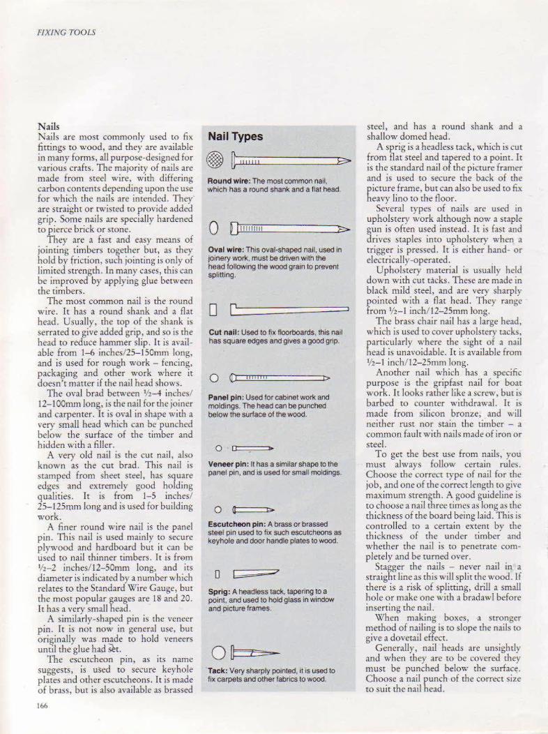
FIXfNG TOOLS
Nails Nails are most commonly used to fix fittings to wood, and they are available in many forms, all purpose-designed for various crafts. The majority of najls are made from steel wire, with differing carbon contents depending upon the use for which the nails are intended. They" are straight or twisted ro provide added grip. Some nails are specially hardened to pierce brick or stone.
They are a fast and easy means of jointing timbers together but, as they hold by friction, such jointing is only of limited strength. In many cases, this can be improved by applying glue between the timbers.
The most common nail is the round wire. It has a round shank and a flat head. Usually, the top of the shank is serrated to give added grip, and so is the head to reduce hammer slip. It is available from 1-6 inches/25-lSOmm long, and is used for rough work - fencing, packaging and other work where it doesn't matter if the nail head shows.
The oval brad between 1h-4 inches/ 12-1 OOmm long, is the nail for the joiner and carpenter. It is oval in shape with a very small head which can be punched below the surface of the timber and hidden with a filler.
A very old nail is the cut nail, also known as the cut brad. This nail is stamped from sheet steel, has square edges and extremely good holding qualities. It is from 1-5 inches/ 25-125mm long and is used for building work.
A finer round wire nail is the panel pin. This nail is used mainly to secure plywood and hardboard but it can be used to nail thinner timbers. It is frE>m V2-2 inches/ 12-SOmm long, and its diameter is indicated by a number which relates to the Standard Wire Gauge, but the most popular gauges are 18 and 20. It has a very small head.
A similarly-shaped pin is the veneer pin. 1 t is not now in general use, but original ly was made to hold veneers until the glue had sh.
The escutcheon pin, as its name suggests, is used to secure keyhole places and ocher escutcheons . It is made of brass, but is also available as brassed
166
Nail Types
~ ~~~~'u''~''~'--------------~~~ Round wire: The most common nail, which has a round shank and a flat head.
0 0,,,,,11,, Oval wire: This oval-shaped nail, used in joinery work, must be dnven with the head following the wood grain to prevent splitting.
0 Cut nail: Used to fix floorboards, this nail has square edges and gives a good grip.
0 {:1 lliiliil
Panel pin: Used for cabinet work and moldings. The head can be punched below the surface of the wood.
0 0 "'
Veneer pin: It has a similar shape to the panel pin, and is used for small moldings.
Escutcheon pin: A brass or brassed steel pin used to fix such escutcheons as keyhole and door handle plates to wood.
0 b ;;;7
Sprig: A headless tack, tapering to a point, and used to hold glass in window and picture frames.
Tack: Very sharply pointed, it is used to fix carpets and other fabrics to wood.
steel, and has a round shank and a shallow domed head·.
A sprig is a headless tack, which is cut from flat steel and tapered to a point. It is the standard nail of the picture framer and is used to secure che back of the picrure frame, but can also be used to fix heavy lino to the floor.
Several rypes of nails are used in upholstery work although now a staple gun is often used instead. It is fast and drives staples into upholstery when a trigger is pressed. It is either hand- or electrical! y -operated.
Upholstery material is usually held down with cut tacks. These are made in black mild steel, and are very sharply pointed with a flat head. They range from 1/2-1 inch/ 12-25mm tong.
The brass chair nail has a large head, which is used to cover upholstery tacks, particularly where the sight of a nail bead is unavoidable. It is available from lf2- 1 inch/ l2-25mm long.
Another nail which has a specific purpose is the gripfast nail for boat work. It looks rather liku a screw, but is barbed to counter withdrawal. Ic is made from silicon bronze, and will neither rust nor stain the timber - a common fault with nails made of iron or steel.
To get the best use from nails, you must always follow certain rules. Choose the correct type of nail for the job, and one of rhe correct length to give maximum strength. A good guideline is to choose a nail three times as long as the thickness of the board being laid. This is controlled to a certain extent by the thickness of the under cimbe~ and whether the nail is to penetrate completely and be turned over.
Stagger the nails - never nail in a straightlineas this will split the wood. Lf there is a risk of splitting, drill a small hole or make one with a bradawl before inserting the nail.
When making boxes, a stronger method of nailing is to slope the nails to give a dovetail effecc.
Generally, nail heads are unsightly and when they are to be covered they must be punched below the surfac~. Choose a nail punch of the correct size to suit the nail head.
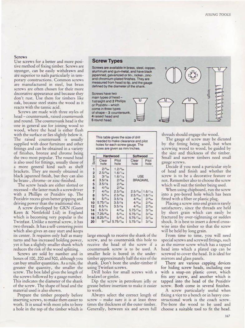
Screws Use screws for a bener and more positive method of fixing timber. Screws are stronger, can be easily withdrawn and are superior to nails particularly in temporary constructions. Common screw!. are manufactured in steel, but brass screws arc often chosen for their more decorative appearance and because they don't rust. Use them for timbers like oak, because steel stains the wood as it reacts with the tannic acid.
Screws are made with three styles of head- countersunk, rai)ed countersunk and round. The coumcr)unk head is the one in general use for joining wood to
wood, where the head is either flush with the surface or lies slightly below it. The raised countersunk is usually supplied with door furniture and other fittings and can be obtained in a variety of finishes, bronz.e and chrome being the two most popular. The round head is also used for fittings, usually those of a more general kind such as shelf brackets. They are mostly obtained in black japanned finish, but they can also be brass-, chrome- or zinc-finished.
The screw heads are either slotted or recessed- the latter match a screwdriver with a Phillips or Pozidriv tip. The Pozidriv recess gives better ~ripping and driving power than the tradttional slot.
A screw developed by GKN (Guest Keen & Nettlefold Ltd) in England \"hich is becoming \'cry popular is the Twinfast. Unlike a normal screw, it has rwo threads. It has a self-centering point which also gives an easy start and keeps its center. It requires only half as many turns and has increased holding power, yet it has a slightly smaller shank which reduces the risk of the wood splitting.
Screws are sold by number and in boxes of 100, 200 and 500, although you can buy smaller quantities. As a rule, the greater the quantity, the smaller the screw. The box label gives the length of the screws followed by a gauge number. This indicates the diameter of the shank of the screw. The shape of head and the material used is also shown.
Prepare the timber properly before inserting screws, to make them easier to work. It is usual with mO)t jobs to bore a hole in rhc tOp of the timber which is
Screw Types Screws are available in brass, steel. copper, aluminum and gun-metal, and have black Japanned, galvanized or tin-. nickel-. zincand chromium-plated finishes. They are measured from head to tJp, and the gauge defined by the diameter of the shank
Screws have two
FIXING TOOLS
main types of head - IT 1 straight and 2 Phillips tr 11 or Pozidriv- wh1ch come in three types of shape - 3 countersunl<. 4 ra1sed head and 5 round head. 3 4 5
;t ~ (.)
(f)
1 2 3 4 5 6 7 8 9
10 12 14 16 18 20
This table g1ves the size of drill needed to make clearance and pilot holes for each screw gauge The sizes are given as mm/inches.
Hardwood Softwood Clear P1lot Clear Pilot hole hole hole hole
2/511A 1.2? .. 2.51%. 1.6/'/, ,
31'1•· 1.61'1 •• USE 3.5/Ye 2/'lfA BRADAWL 3.5/Ya 2/' .,.
41'1.. 21' .. 4/5in 2.5/'.sz 2.5t•, .. 1.6/'· .. 51•1 .. 2.5Pu 2.51'/n 1.6/' ,. 5/3/,. 3.5/h 4/'lsa 21'1 ..
5.75/'1 .. 3.5/~ 4/'lu 21'1 .. 6.5/Y• 3.5/~ 4/1/n 21'1 .. 6.5/Y• 4/'.n 5.75/'/u 31'' ..
7.25/'t.. SP,. 5.75/ 71., 31'' .. 8.25/'/,. 51' •• 5.751'1 •• 31' lA
9/"/so 5.751'/u 5.751'1 .. 31'' ..
large enough to receive the ~hank of the !>Crew, and to countersink this hole to receive the head of the !>Crew if a countersunk screw is to be used. A smaller hole is bored in the undertimber approximately half the size of the shank. Don't bore the under-timber if using Twin fast screws.
Drill hole!> for small screws with a bradawl or gimlet.
Dip the screw in petroleum jelly or grease before insertion to make it easier tO work.
Always select the correct length of screw - make sure it is at least three rimes the thickne)s of the outer timber. Generally, between six and seven full
threads should engage the wood. The gauge of screw may be dictated
by the fitting being used, but when !>Crewing wood to wood, be guided by the s ize and thickness of the timber. Small and narrow timbers need )mall gauge screws.
Decide if you need a particular style of head and finish and whether the screw is to be a decorative feature or not. Remember also to choose the screw which will suit the timber being used.
When using chipboard, run the screw into a pre-bored hole which has been fitted with a fiber or plastic plug.
Placing a screw into end grain is rarely satisfactory, !Iince the threads are held b) shorr grain \\hich can ea)ily be fractured by over-tightening or sudden shock. It is best to insert a dowel crosswise into the timber so that the screw will be held by long grain .
From time to time, you will need '>pecial screws and ~crewed fining~, such a'> the mirror screw which has a tapped head into which a plated cap can be screwed to cover rhe head. It is ideal for mirrors and glass panels.
There are various capping devices for hiding screw heads, including one with a snap-on plastic cover, which fits any screw, and another which is tapped into the head of the Pozidriv screw. Both come in several finishes.
A screw particularly useful when fixing a vice to a bench or in heavy constructional work is the coach screw. Pre-bore the v .. ·ood to be used and choose a suitable tool to fit the head.
167

16!\

CHAPTER FOURTEEN
Power Tools The earliest, and
possibly the most influential, power tool is the electric hand drill. Today, few homes are without one.
169
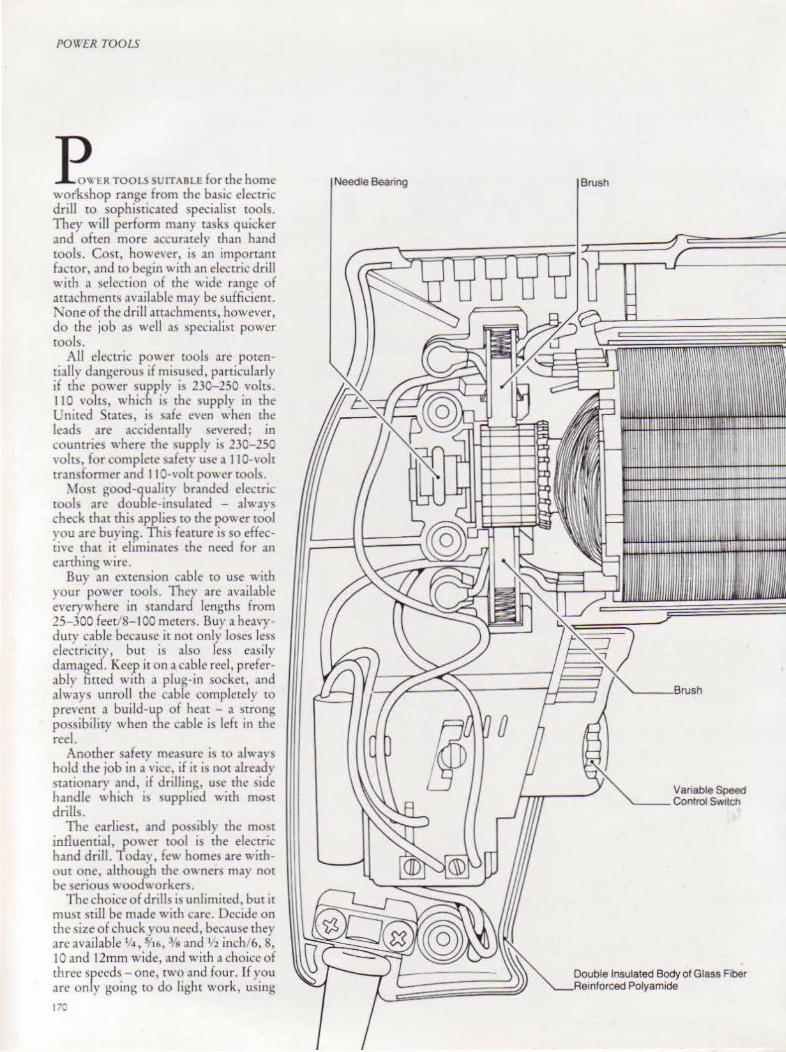
POWER TOOLS
E <R TOOLS SUIT ABLE fonhe home workshop range from the basic electric drill tO sophisticated specialist tools. They will perfonn many tasks quicker and often more accurately than hand tools. Cost, however, is an important factor. anu £0 begin with an electric drill with a selection of the wide range of auachments available may be sufficient. 0:one of the drill attachments, however, do the job as well as specialist power rools.
All eb:tric power tools are potentially dangerou~ if misu~cd, particularly if the power supply ic; 230-250 voir~. II 0 voles, which is the supply in the United Stares, is safe even when the leads are accidentally severed; in countries where the supply is 230-250 \'Oits, for complete safety use a 110-\·olt transformer and 110-volt power tools.
~fO!>t good-qualny branded electric rools arc double-insulated - alwavs check that this applies to the power to'ol you arc buying. This feature is so effectiYe that it eliminates the need for an earthing wire.
Buy an cxtemion cable to use \\ ith your power took They arc available everywhere in standard lengths from 25-300 feet/8-100 meters. Buy a heavyduty cable because it not only loses less electricity, but is also less easily damaged. Keep it on a cable reel, preferably fitted with a plug-in socket, and always unroll the cable completely to prevent a build-up of heat - a strong possibiliry when the cable is left in the reeL
Another safety measure is to always hold the job in a vice, if it i~ not already stationary and, if drilling, usc the side handle "hich is o;upplied with most drills.
The earliest, and possibly the most influential, power tool is the electric hand drill. Todav, few homes are without one, although the owners may not be serious wood\' orker~.
The choice of drills is unlimited, bur it must still be made with care. Decide on the size of chuck you need, because they arc available V4, 5116, 3/s and Vz inch/6, 8, I 0 and 12mm wide, and with a choice of three speeds - one, two and four. If you are only going to do light work, using 1"'0
Beanng Brush
'---Brush
Variable Speed '---Control Swllch
Double Insulated Body of Glass Fiber l'lointnr'l'l<:l>/1 Polyamide
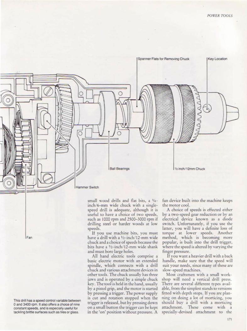
PO'J'ER TOOLS
Spanner Flats for Removing Chuck Key Localton
Ball Beanngs
Hammer Switch
Fan
Th1s dnll has a speed control variable between 0 and 3400 rpm. It also oHers a choice of nine constant speeds, and is espec1ally useful for tackhng bnttle surfaces such as t1les or glass.
small wood drills and flat bits, a 114-
inch/6-mm wide chuck with a singlespeed drill is adequate, although ir i~ useful to have a choice of two speeds, such as 1000 rpm and 2500-3000 rpm if drilling steel or harder woods ,u low speeds.
If you use machine bits, you must have a drill with a 1/2-inch/ 12-mm wide chuck and a choice of speeds because the bits have a Y2 -inch, 12-mm wide ~hank and must bore large holes.
All hand electric tools compri)e a basic electric moror with an extended spindle, which connects with a drill chuck and various attachment devices in other tools. The chuck usually has three jaws and is operated by a simple chuck kev. The tool i'> held in the hand, usuallv b}; a pistol grip, and the motor i~ ~carted by pressing a trigger. The power supply is cut and rotation ~tOpped when the trigger is released, but by pressing down on a small button the trigger can be kept in the 'on' position without pressure. A
Y2 inch/ 12mm Chuck
fan device built into the machine keeps the motor cool.
A choice of speeds is effected either bv a two-speed gear reduction or b) an efcctrical device known as a diode switch. Unfortunately, if you use the larter, you will have a definite loss of torque at lo\\·er speeds. Another method, which is becoming more popular, is built into the drill trigger, where the speed i\ altered by vary in~ the finger pressure.
If you want a hea,•ier drill with a back handle, make sure that the speed will suit your needs, since many of these are slow-speed machines.
Most craftsmen with a small workshop will need a \ ertical drill prc~s. There are everal different rype) available, from the simplest stands ro vcr~ions fined with depth )tops. If you arc planning on doing a lot of morticing, you should buy a drill with a morcicing attachment. Thc~e come with a specially-devised attachment to the
171

POWER TOOLS
A mortice stand is shown right, with the mortice attachment in close-up above.
stand which holds the shank of the square chisel while the bit runs inside and is motivated by being held in the driJI chuck. A clamping device is attached to the base for holdi ng and accurate positioning of the timber. You could also add a depth-setting device with a micrometer-type adjustment. Check that your drill will match the stand - many stands have interchangeable fittings which will take a variety of electric hand drills. Bolt the drill stand firmly to the bench and use a guard.
Few drill stands have drill press vices fined, but small work must be held safely with the fingers as far away from the moving boring cool as possible. Drill press vices can be bolted to the base of the stand and have capacities of more than 4 inchcs/lOOmm. If you do use one, you must protect the wood by placing a small piece of timber between the wood and the base of the vice. .
If you are using a drill stand with small work. it is important to use a drill press vice.
172
j ..

Hand Power Saws The circular sawing of wood uses a great deal of power, so it is essential to keep the saw in perfect condition to obtain the best results. The cheap hand power saw and saw attachment can both be poor investments. However, a wellchosen saw can be quick and accurate. With correctly-selected saw blades, it can cut a wide variety of materials, and when fitted with abrasive disks, its range is extended to cut such articles as brick, concrete, slate and asbestos.
There are three variations of saw, the most common of which is the handheld, which has a blade with a diameter from S-9 inches/ 12S-225mm. The blade
is vertically mounted on the shaft of th<! motor and secured with a nut, and the attachment is fitted with a sole, on which the saw runs, a fence and an automatic saw guard. This moves around the saw when sawing but automatically drops into place for safety whenever the saw is removed from the timber. The sole can be tilted for angular cuts. Fitted with the normal trigger, it also has a button which locks it in continuous rotation.
A number of manufacturers make a saw table, to which a power saw can be fitted. Usually, the saw is attached by screws through its sole to the underside of the table. In the upward position, the
POWER TOOLS
blade passes through the table. These tables are usually fined with a fence and riving knife exactly as the commercial circular saw. Both hands are free to push the wood through the saw, but always use a push stick to keep your fingers well away from the blade.
The third variation converts rhe ~aw to a radial arm saw. This is an anachment for the saw which comprises a sliding arm on the pillar of the drill stand. Place the saw on a purpose-built wooden table. It slides along its horizontal am1, and can be set at any posi tion along the wood. This is certain!) not as sophisticated as the popular radial arm saw, but is adequate for limited u~c.
A general ru le for circular saws such as the one shown left is that smoothness of cut increases with power and speed. You should check how far speed is maintained under load. Slow down of about two· fifths under full load is normal. Kickback is ehmmated 10 modern tools by use of a slip crutch. Above, the Jl9 saw with 1ts short narrow blade IS desagned for enclosed cun1ng cuning into w1de sheets and cutting curves
173

PO\l ER TOOLS
Right, a circle-cutting guide can be attached to the np fence to cut perfect circles. Below, the sole plate of the jig saw can be adjusted to cut a bevel. lt1s important to avoid forcing the saw, to keep 1ts base flush w1th the surface of the work. and to watch out tor the edge of the blade touch1ng clamps hold1ng the work.
Choose the saw attachment with care and make sure that not only will it fit your drill, but that it will not need more power than your drill can provide. The si7e of the center hole of the !law blade mu~t m.uch that of the drill chuck arbor, and the body of the drill must, of course, accept and hold the body of the attachment securely.
Another extremely useful saw, ideal for cutting curves and also cutting into wide sheets, is the jig saw. This is avail-174
able with an integral motor or as an attachment to a power drill. Once again, it consists of a simple electric motor, with a spindle connected to a cam mechanism to gi'e an up-and-down reciprocating mmion to a short, narrow blade. Some models have two speeds or one variable speed. In l>Ome machines, a tube directs air from the motor to behind the saw blade to blow fine saw dust away from the work. There is a limit to the thickness of the wood ro be
cut, but most machines can cut wood up to 2 inches/50mm thick. Slowly move the roo! into the wood, and don't cut curve~ beyond the capacity of the blade - it will not turn right-angled corner\ . I·or enclosed cutting, such al> c1rdes within a <ihcet, tilr the jigsaw forward onto its nose, and gradually lower the blade until it passes through the timber, with the machine finally resting in the vertical posicion. If you decide to bu) a drill attachment, make sure that it fits.
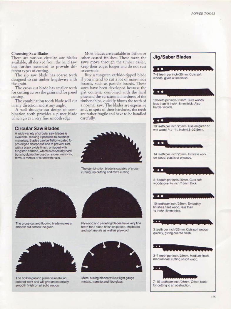
Choosing Saw Blades There are various circular saw blades available, all derived from the hand saw but further extended to provide different types of cutting.
The rip saw blade has course teeth designed to cut timber lengthwise with the O'rain.
The cross cut blade has smaller teeth for ~utting across the grain and for panel cuttmg.
The combination tooth blade will cut in any direction and at any angle.
A well-thought-out design of combination teeth provides a planer blade which gives a very fine smooth edge.
Circular Saw Blades A w1de variety of circular saw blades is available, making it possible to cut most matenals. Blades can be Teflon-coated for prolonged sharpness and to prevent rust, with a black oxide finish, or lipped with tungsten carbide, which is especially hard but should not be used on stone, masonry, ferrous metals or wood with nails.
The cross-cut and flooring blade makes a smooth cut across the grain.
The hollow ground planer is useful on cabinet work and will give an especially smooth finish on all solid woods.
Most blades are available in Teflon or orher coated finishes. These mean the saws move through the timber easier, keep their edges longer and do not rust or corrode.
Buy a tungsten carbide-tipped blade if you intend to cut a lot of man-made boards, such as particle boards. These saws have been developed because the grit content, combined with the hard glue and the variation in hardness of the timber chips, quickly blunts the teeth of a normal saw. The blades are expensive and, in spite of their hardness, the teeth are rather fragile and have to be handled carefully.
The combination blade 1s capable of cross· cutting, rip-cutting and mttre cutting.
Plywood and paneling blades have very fine teeth for a clean fln1sh on plastic, chipboard and soft metals as well as plywood.
Metal slicing blades will cut light gauge metals, transite and fiberglass
POWER TOOLS
Jig/ Saber Blades
1 0 teeth per inch/25mm. Cuts woods less than ¥4 inch/1 8mm thick. Also harder woods.
10 teeth per inch/25mm. Use on green or wet wood, •;,.,-••t •• tnch/4.5-32.5mm. ,,, 14 teeth per inch/ 25mm. Intricate work on wood, plastic or plywood.
5-6 teeth per inch/25mm. Cuts soft woods over% inch/18mm thick.
3 teeth per inch/25mm Cuts soft woods qu1ckly, giving coarse ltnish.
7-10 teeth per inch/25mm. Offset blade for cutting to an obstruction.
t7S
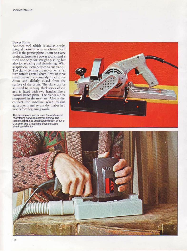
POWER TOOLS
Power Plane Another tool which is available with integral motor or as an anachment for a drill is the power plane. It can be a very useful addition to a power tool kit and is used not only for straight planing but also for rebating and chamfering. With adaptation, it can be used to cut tenons. The planer consists of a motor, which in turn rotates a small drum. Two or three small blades are accurately fitted to the drum and slightly raised from the surface of the drum. The plane can be adjusted to varying thicknesses of cut and is fitted with rwo handles like a normal bench plane. The blades can be sharpened in the machine. Always disconnect the machine when making adjustments and secure the timber in a vice before beginning work.
The power plane can be used for rebates and chamfering as well as normal planing. The version, right, has an adjustable depth of out of 0..3.2mm and a reversible dust and wood shavings deflector.
176
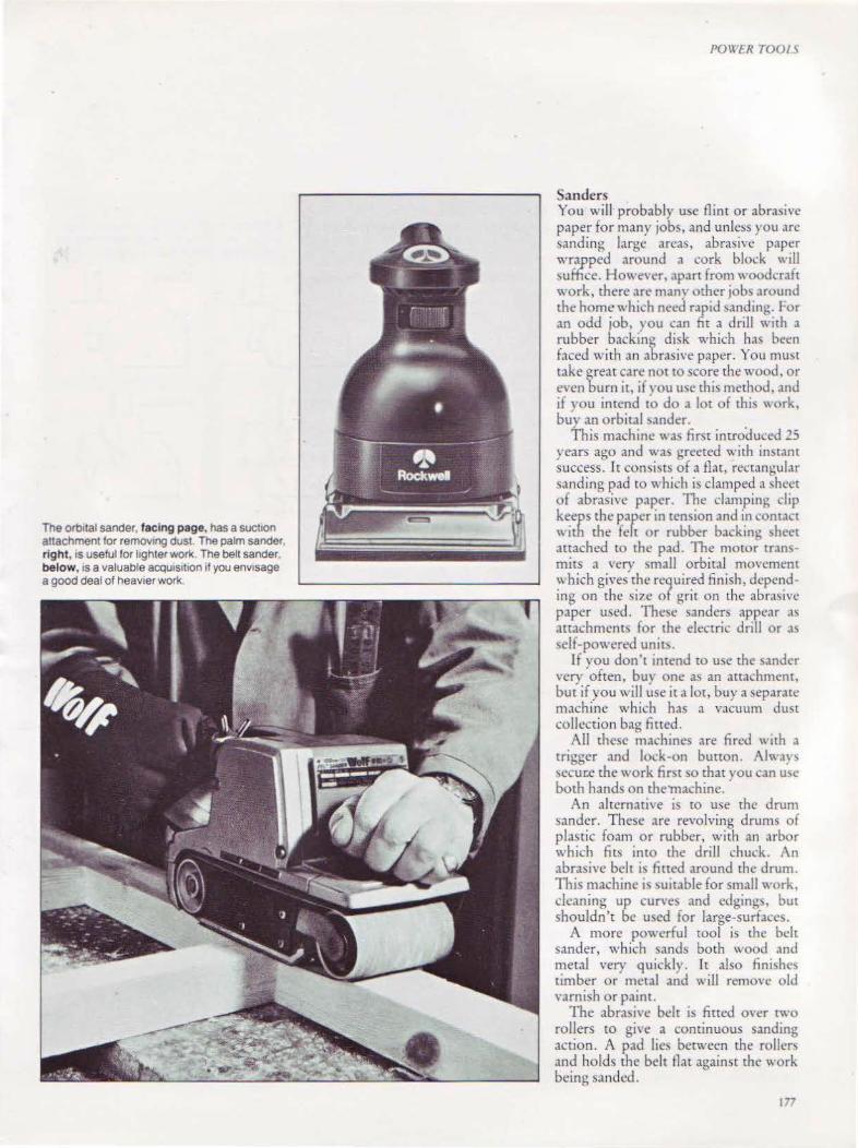
The orb1tal sander, facing p age, has a suct1on attachment for remowlg dust. The palm sander r ight, is useful for lighter work The belt sander, below, IS a valuable acquiSition if you envisage a good deal of heav1er work.
POIX'ER TOOl 5
Sanders You will probably use flint or abrasi,·e paper for many jobs, and unless you arc sanding large areas, abrasive paper wr~pped around a cork block will .,uffice. However, apart from'' oodcraft work, there are many other job' around the home which need rapid sanding. tor an odd job, you can fit a drill with a rubber backing disk which has been faced with an abrasive paper. You must take great care not to score the wood, or even burn it, if vou usc this method, .tnd if vou intend to do a lot of thi~ '' ork, bu'v an orbital sander.
This machine "as first introduced 25 years ago and wa:. greeted with instant success. Tt consists of a flat, rectanhular sanding pad to which is clamped a \hcet of abrasive paper. The clamping dip keeps the paper in tension and in c.:ont.tet '' ith rhe felt or rubber back in~ sheet attached to the pad. The moror transmits a very small orbital movcmem which gives the required finish, depending on the ~i7.c of grit on the abnuivc paper used. These sanders appt>ar as attachments for the electric drill or as self-po\\·ered unit .
If you don't intend to use the sander very often, buy one as an attachment, but if you will use it a lot, buy a separate machine which has a vacuum dust collection bag fitted.
All these machines are fired with a trigger and lock-on button. AI\\ an sccur:e the work first so that you can u<,e both hands on the·machine.
An alternative is to use the drum sander. These are re\'olving drums of plastic foam or rubber, with an arbor which fits into the drill chuck. An abrasive belt i~ fitted around the drum. This machine is '>Uitable for small work, cleaning up cun·es and edgings, but shouldn't be used for large-surfaces.
A more powerful tool is the belt s,mder, which sands both wood and metal very quickly. It also fini~hes timber or metal and wilJ remove old varnish or paint.
The abrasi,·e bdt is fitted o,·er two rollers to give a continuous sanding action. A pad lies between the roller~ and holds the belt flat against the work being sanded.
177
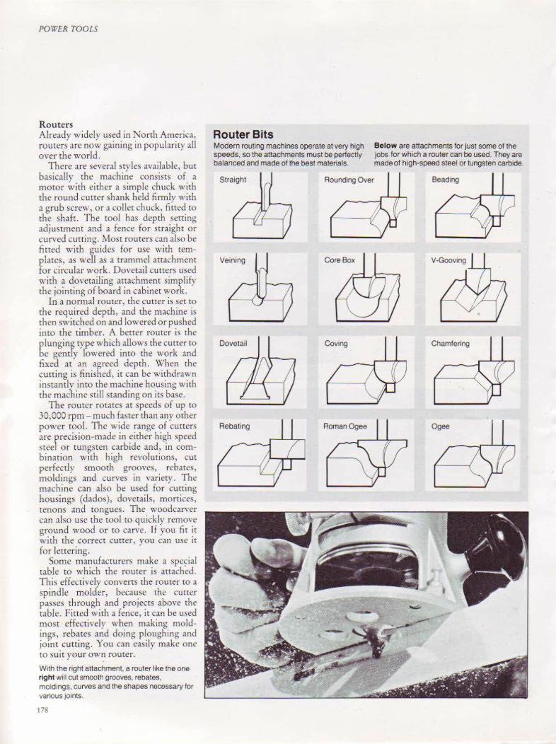
POWER TOOLS
Routers Already widely used in North America, routers are now gaining in popularity all over the world.
There are several styles available, but basically the machine consists of a motor with either a simple chuck with the round curter shank held firmly with a grub screw, or a collet chuck, lined to the shaft. The tool has depth setting adjustment and a fence for straight or curved cutting. Most routers can also be fitted with guides for use with templates, as well as a trammel attachment for circular work. Dovetail cutters used with a dovetailing attachment simplify the jointing of board in cabinet work.
In a normal router, the cutter is set to the required depth, and the machine is then switched on and lowered or pushed into the tin1ber. A better router is che plunging type which allows the curter ro be gently lowered into the work and fixed at an agreed depth. When the cutting is finished , it can be withdrawn instantly into the machine housing with the machi ne still standing on irs base.
The router rotates at speeds of up tO
30,000 rpm- much faster than any ocher power cool. The wide range of cuners are rrecision-made in either high speed stee or tungsten carbide and, in combination with high revolutions, cut perfectly smooth grooves, rebates, moldings and curves in variety. The machine can also be used for cutting housings (dados), dovetails, monices, tenons <tnd tongues. The woodcarver can also use the tool tO quickly remon• ground wood or to carve. If you fit it with the correct cutter, you can usc it for lettering.
Some manufacturers make a spe~ial tabk to which the router is attached. This effectively converts the router to a spindle molder, because the cutter passes through and projects ~bove the table. Fitted with a fence, it can be used most effectively when making moldin~s, rebates and doing ploughing and jomt cutting. You can easily make one to suit your own rourcr.
With the right attachment, a router like the one right will cut smooth grooves, rebates, moldings. curves and the shapes necessary for various joints.
178
Router Bits Modern routing machines operate at very high speeds, so the attachments must be perfectly balanced and made of the best materials.
Rounding Over
Veining
Dovetail
Rebating RomanOgee
Below are attachments for just some of the jobs for which a router can be used. They are made of high-speed steel or tungsten carbide.
Chamfering

Bench Grinders An additional power tool which you might find useful is the bench grindt:r. Since most people hate sharpening tools and ha\c little or no experience in grinding them, this machine removes a great deal of frust ration.
An electric motor is fitted with rwo shafts, one at each end. Grinding wheels with various grades of cutting grit are .machcd to the shaftS, and the wheels are held in place by nutS 't\·hich screw do" n onto a collar on the threaded shaft. The left-hand wheel is held by a left-handed screw and nut to preYent it working loose while in use.
Similarly, the wheel on the right is right-handed. Each wheel has a spark
guard and an adjustable tool rest to take up "heel wear, and both arc shrouded to prevent accidents. These tools are supplied with one fine and one coarse ''heel, usually of manufacturd grir. One or two European grinders sell rubberized abrasive wheels, and these are superb for grinding and sharpening, as they have a 'el) gentle action even when the coarse wheel is used, and the bevels polish the '' ood to make it easier to cur. These ''heels will re,·olutionize tool sharpening, particularly for the home craftsman and amateur.
As an alternative to a bench grinder, use a horizontal drill stand in conjunction with a power drill. Most of these stands are available "ith a grinding
PO\VER TOOL5
A grinding mach1ne such as the one lett, would be a prized and useful acquisition, but many woodworkers would probably find lhat a dnll attachment such as the one shown below would suit lhe1r purposes adequately. The flex1ble shaft bottom IS useful for f1ne work such as caNing. It IS also handy 1n confined spaces
wheel arrachment. The stand must match the drill and be screwed down fim1ly to either a bench or a board.
Flexible Shafts The flexible shaft is a useful accessory for the power drill. It is merely an extension of the drive through a flexible shaft to another chuck into which can be fined flap wheels, small cutters, drills and a host of other cutting aids . Th1<. tool is particular!) useful'' hen workmg in enclosed spaces and so is suitable al~o for the carver and sculptor. The more expensive shafts can be fined with various attachments and tools, and they can also run from an electric motOr, drill ing machine, grinder or lathe.
179
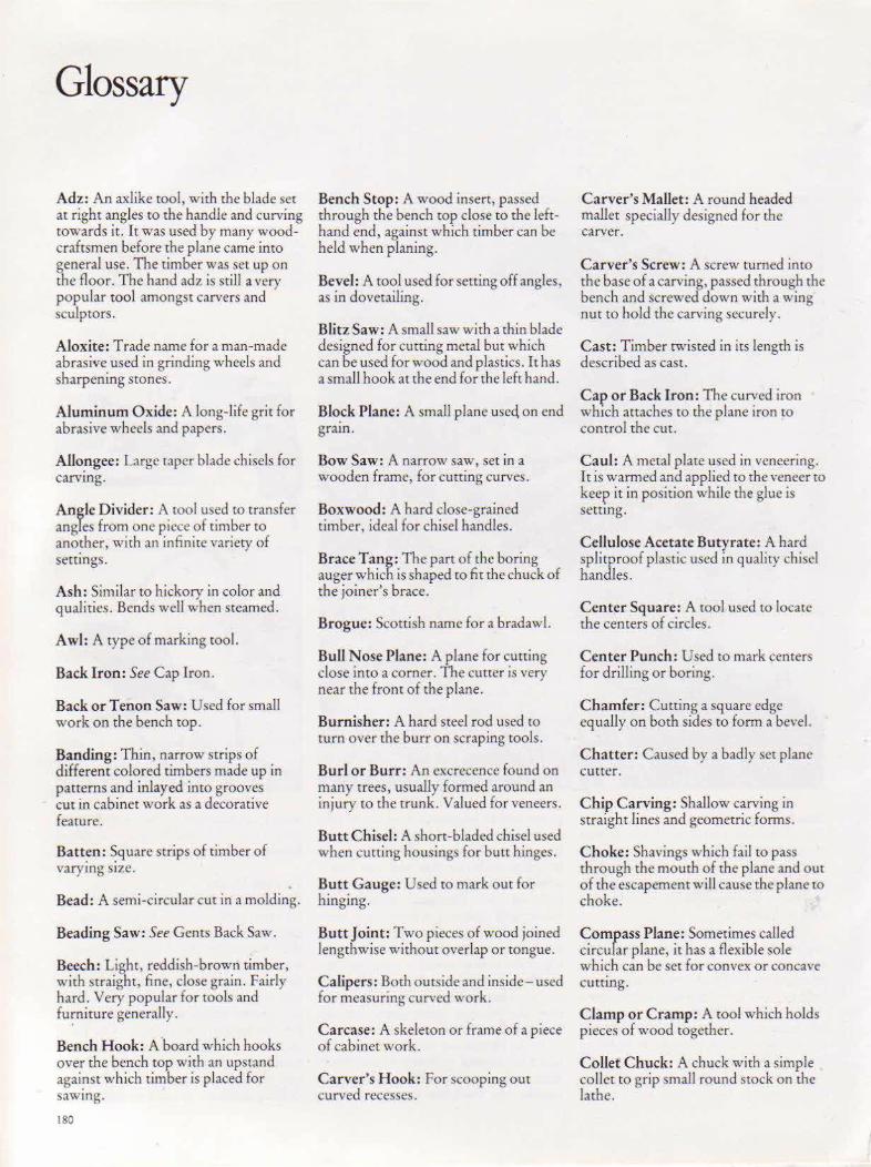
Glossary
Adz: An axlike tool, with the blade set at right angles to the handle and curving towards it. It was used by many woodcraftsmen before the plane came into general use. The timber was set up on the floor. The hand adz is still a very popular tool amongst carvers and sculptOrs.
Aloxite: Trade name for a man-made abrasive used in grinding wheels and sharpening stones.
Aluminum Oxide: A long-life grit for abrasive wheels and papers.
Allo!lgee: Large taper blade chisels for carvmg.
A n gle Divider: A tool used to transfer angles from one piece of timber to ano~er, with an infinite variety of seumgs .
Ash: Similar to hickory in color and qualities. Bends well when steamed.
Awl: A type of marking tool.
Back Iron: See Cap Iron.
Back or Tenon Saw: Used for small work on the bench top.
Banding: Thin, narrow strips of different colored timbers made up in patterns and inlayed into grooves cut in cabinet work as a decorative feature.
Batt~n: ~quare strips of timber of varymg SIZC.
Bead: A semi-circular cut in a molding.
Beading Saw: See Gents Back Saw.
Beech: Light, reddish-brown r,imber, with straight, fine, close grain. Fairly hard. Very popular for tools and fu;nirure generally.
Bench Hook: A board which hooks over the bench top with an upstand agai!lst which timber is placed for sawtng.
180
Bench Stop: A wood insert, passed through the bench wp close to the lefthand end, against which timber can be held when planing.
Bevel: A tool used for setting off angles, as in dovetailing.
Blitz Saw: A small saw with a thin blade designed for cutting metal but which can be used for wood and plastics. It has a small hook at the end for the left hand.
Blo.ck Plane: A small plane useq on end gram.
Bow Saw: A narrow saw, set in a wooden frame, for cutting curves.
Boxwood: A hard close-grained timber, ideal for chisel handles.
Brace Tang: The part of the boring auger which is shaped to fit the chuck of tbe joiner's brace.
Brogue: Scottish name for a brad awl.
Bull Nose Plane: A plane for cutting close into a corner. The cutter is very near the front of the plane.
Burnisher: A hard steel rod used to turn over the burr on scraping tools.
Burl or Burr: An excrecence found on many trees, usually formed around an injury to the trunk. Valued for veneers.
Butt Chisel: A short-bladed chisel used when cutting housings for butt hinges.
Butt Gauge: Used to mark out for hinging.
Butt Joint: Two pieces of wood joined lengthwise without overlap or tongue.
Calipers: Both outside and inside- used for measuring curved work .
Carcase: A skeleton or frame of a piece of cabinet work.
Carver's H ook: For scooping out curved recesses.
Carver's Mallet: A round headed mallet specially designed for the carver.
Carver's Screw: A screw turned into the base of a carving, passed through the bench and screwed down with a wing nut tO hold the carving securely.
Cast: Timber twisted in its length is described as cast.
Cap or Back Iron: The curved iron wh1ch attaches to the plane iron to control the cut.
Caul: A metal plate used in veneering. It is warmed and applied to the veneer to keep it in position while the glue is seumg.
Cellulose Acetate Butyrate: A hard splitproof plastic used in quality chisd handles.
Center Squ are: A tool used to locate the centers of circles.
Center Punch: Used to mark centers for drilling or boring.
Chamfer: Cutting a square edge equally on both sides to form a bevel.
C hatter: Caused by a badly set plane cutter.
Chip Carving: Shallow carving in straight lines and geometric forms.
Choke: Shavings which fail to pass through the mouth of the plane and out of the escapement will cause the plane tO choke.
Compass Plane: Sometimes called circular plane, it has a flexible sole which can be set for convex or concave CUtting.
Clamp or Cramp: A mol which holds pieces of wood together.
Collet Chuck: A chuck with a simple collet to grip smaH round stock on the lathe.
Collar Chuck: Used for mounting timber on the lathe for egg cups, etc.
Drill Chuck: Used in the wood lathe tailstock to hold machine boring bits.
Combination Plane: A plane capable of Edging Tool: For trimming .veneer. ploug~ing, rebating, beading and tongumg.
Compass Saw: A thin taper bladed saw for cutting tiny holes.
Concave: Hollowed out.
Cone Center: Mounted on the headstock for driving square material without centering.
Convex: Bulging out.
Copying Attachment: A device to set the lathe for repetition work.
Corrugated Base: A series of longitudinal grooves cut in the soles of bench planes to relieYe the suction between the wood and the sole of the plane, giving easier cutting.
Cove: A concave cut.
Crotch: A veneer which has been cut from a limb crotch.
Cr?SS Cut: A saw for cutting across the gram.
Curl: Feather grain found in timber, mainly mahogany.
Dado: A groove or housing made across the grain.
Deal: A word used loosely to describe timbers cut from pine or fir logs.
Dog: A peg inserted into a hole in the bench top and used in conjunction with a tail vice to hold timber securely.
P?w.cl : A round pin or peg used in JOinttng.
Draw Knife: A two-handed tool much fa,·ored by the carrwright and " 'heelwright for shaping and ch.1mfermg. There arc many variations available.
End Grain: Timber grain which shO'\\'S when a piece is cut tran~,·crsely.
Expanding Collar Cht.ick: A six-inone chuck which eliminates the need for faceplates, collar chucks, screw chucks, etc.
Face Side and Face Edge: The accurately planed face and edge of a board or batten from which all marking out is done .
Fence: A part of awol designed to limit movement, as in the fence of the plough plane.
Fiddleback: Design of a chairback. It also refers to the grain of timber which shows a rippling effect. Very much prized in the backing timber for violins.
Figure: The formation of grain.
Fillet: A strip of rimber added to work either as a guide or a support.
Fillister: A rebate plane used in cutting sash windows and other work.
Finger Plane: A smaJI plane used by the violm-maker.
Flapwheel: Flap of abrasive paper, attached to a center core and used in an electric drill.
Flat or Spade Bit: Designed for use in electric drills.
Fleam: The teeth of a cross cut saw, which are shaped like an isoceles triangle . Ideal for quick cutting.
Flooring Saw: A special saw forcuning floo~ing - useful to the electrician in parucular.
Fluteroni: Wide U-shaped carving gouge with round corners for shaping round sides.
GLOSSARY
Fore Plane: A plane between the trying plane and the jack plane in length.
Forstner Bit: An auger bit which runs on its periphery, used exclusively for boring shallow, flat-bottomed holes.
Frame Saw: A saw with a narrow blade tensioned and supported in a wooden frame.
Frog: The device in a plane which holds the cutter in place and which can be adjusted to control the cutting.
Gain: A recess to receive a butt hinge.
G Cramp or Clamp: So-called because it is similar in shape to the letter G. It is used for small cramping work.
Geelim: The Scottish name for a shoulder plane.
Gents Back Saw: A small saw with round handle and thin blade, used for dovetail cutting and small work.
Green Wood: Unseasoned or newly felled timber.
Grinding: Resharpening badly-worn or -shaped cutters by holding them against a rotating wheel.
Grounding: Cutting away the background in a low-relief carving.
Hardwood: Generally the timber of deciduous trees.
Heartwood: The best timber, which comes from rhe heart of tbe tree and has matured with age.
Heat Treatment: The hardening and tempering of cutting steels to ensure long-lasting cutting edges.
Hickory: Whitish-yellow in color, very tough hard elastic and strong, ideal for hammer handles.
Hogging: Rough planing of timber, usually with a jack plane that has a slightly rounded cutter.
181
GLOSSARY
Holdfast: A clamping device, dropped through a hole in the bench top and used to secure timber for can·ing and other work.
Honing: The fine sharpening of a curring edge using a fine sharpening stone, called a hone.
Honing Guide: A device to hold chisels and plane cutters at a constant angle during sharpening on an oilstone.
Horn: The forward handle fined on the older planes.
Housing or Dado: A groove cut across a board to receive a shelf:
In-Cannel: A gouge ground on the inside.
Inlay: A form of decoration where pieces of wood and other materials are set into a base of wood and left flush.
Inshave: A tool similar to the draw knife but which has a curved blade for hollowing our.
Iron: The cutter of a plane or spokeshave. These were originally made of iron with the cutting steel face welded on.
Lengthening Bar: An addition ro a sash cramp to give added capacity.
Lignum Vitae: The tree of life- it produces an extremely hard wood with an oiJ secretion useful for bearings. Highly priz.cd for small planes and plane soles.
Live Center: See Running Center.
Log Saw: A thin-bladed saw with a tubular frame used for logging and large rough work.
Long and Strong: \X'oodturning tools with thick strong blades and matching handles .
Macaroni: Wide U-shapcd carving gouge with square corners, designed for finishing the sides of shallow recesses.
Mahogany: Reddish-brown timber, fairly hard, with many varieties. Once used as a base for veneered furniture.
Makrolon: A flexible plastic material used to make modern rules.
Mandrel: A lathe attachment used to mount timber on the lathe fo r turning.
Mitre: The joining of timber by cutting Jack Plane: Takes irs name from 'Jack of it at an evenly divided angle- usually all Trades'. It is the most commonlr 45°. used plane.
Jointer: A long plane, panicularl) ~~.ef~l when planing long boards for rub JOinting.
Keying: An addition to a piece of wood used to strengthen it. Dovetail keying is where the piece of wood is inserted into a dovetailed housing to prevent a board from warping.
Keyhole Saw: Similar to the compa~~ saw, having a thin tapering blade for cutting keyholes and similar slots.
Knot: The very hard wood at the junction of a branch, sometimes completely circular and loose.
182
Mitre Square: A tool incorrectly named, which is used to test and mark lines at 45°.
Morse Taper: Both head and tailstock of the lathe are bored on a un iversally agreed taper to recei\'e standard components.
Multi-Plane: A plane capable of many types of cuts.
Multispur Bit: See Saw Tooth Machine Bit.
Nosing: The front of a stair tread.
Ogee: A type of molding.
Oilstone Slip: A shaped oilstone for -;harpcning gouges.
Old Woman's Tooth:.An earlv n.une for the router plane. •
O ut-Cannel: A gouge ground on the outside.
Ovolo: A type of molding .
Palm Plane: A plane which comfortably firs into the hand. rt i~ useful for the musical-instrume!1lmaker and others handling small \vork.
Parting Tool: Tool for paning off work on the \Vood lathe.
Plinth : A receding p:m of a cabinet next to the floor.
Plough: A plane for maki ng grooves or rebates.
Plug Cutter : A special machine cuncr for cutting wooden plug!>.
Pocket Chisel: See Burr Chisel.
Polypropylene: A plastic material used in the making of tool handles, which is practically indestructible.
Purfling Tool: Violin-maker\ groo,·er.
Quick Gouge: A deep carving gouge used for roughing out.
Rail: The horizontal member of a frame or carcase.
Rebate or Rabbet: A cut made on the edge of a frJme or board to receive gla~~ or a wooden panel.
Reform Plane: A l70ntinental plane '' ith an adju~table mouth.
Registered Pattern : A thicker-bladed chisel with steel hoop and ferrule, often called a mortice chisel.
Revolving Cone Center: To hold squa.re mrnerial in the milstock for turn mg.
Rifflers: Double-ended ra~ps or files for the "'oodcarver.
Rip Saw: A saw with special teeth for cutting with the grain.
Rosewood: Be,mriful, dark purpl~/ brown-colored timber used for expensi' e cabinet work, tool handles and other components.
Router: A hand or machine roo! used ro make a variety of cuts.
Running or Revolving Center: A center running in a ball race and mounted in the woodturning lathe tailstock.
Sap"ood: Timber immediately underneath the bark, still growing and too young for use by rhe woodcraftsman.
Saw Set: A pincer-like roo) for setting aw teeth.
Saw Tooth or Multispur Bit: A machine bit with saw-like teeth around its periphery which is designed to cut ~hallow or deep holes in any timber.
Scant: The bare measure.
Scopas C hops: A carver's sculptor's "ice, made of wood with a central screw for mounting to the bench top. It has a ?eep capacity, with leather-protected JaWs.
corp: A circular-bladed carver's tool.
Scraper: Used in the hand ro finish after planing.
Scratch Stock: A small tool used to cut ~hallo"· recesse~ for inJaying.
Screw Chuck: A chuck with ~ingle <,crew for mounting small work on the lathe.
Screwdriver Bit: A brace bit "'ith a o,crewdriver end.
Scrub Plane: A roughing plane.
Set: The inclination of alternate teeth of the saw to the right and left. Also, the distance the cap iron is set back from the cutter edge in the plane.
Shake: A seasoning split seen in timber.
Sharpenset : A fine "'et grindstone.
Shoulder Plane: A precision plane used to trim end grain before jointing.
Silicon Carbide G rit: Used on wetand-dry abrasi,·e paper~. The paper and glue are waterproof, permitting the paper to be used wet.
Sizing Tool: For accurate si1ing and setting out on the lathe.
Skew Chisel: For planing wood between lathe tenters, squaring, beading, curving and tapering.
Slow Gouge: A shallow carving gouge for finishing work.
Spalted Timber: Timber whi ~.:h i~ brittle through decay.
Spindle Gouge: Round nose gouge for coving in spindle work on the lathe.
Spokeshave: A cutting tOol with two handles used for small curved work. It has a similar action to the plane.
Spurs: The small cutters of the combination, fillister and multi-plane, brought imo usc when cutting across the grain to sever the top fibres .thead of the cutter.
St ringing: Tiny strips of thin square or rectangular section timber used in inlaying.
Surform: Registered name for a new patterned file.
Tail Vice: A vice at the end of a bench which uses dogs to clamp boards for planing, etc.
Tenon: The male part of the joint which tits into the mortice.
GLOfiSAR'f
Toat: Anmher name for the plane handle. ·
Toothing: The roughing of the surface of timber to provide keying for veneer.
Trammel Point: Used in conjunction with a beam to mark our large circular \\'Ork.
Tryin~ Plane: A long bench plane used as the JOinter.
Tungsten Carbide Grit: The ultimate in man-made abrasive grits.
Vee Parting Tool: V -shaped carving tool for marking out texturing and lettering.
Veneer : Thin timber glued to a solid timber background for decoration, enabling the use of rare and exotic woods not available in solid form.
Veneering Hammer: Tool used when gluing veneers.
Ven~er Punch: A punch for veneer repatrs.
Veiner : A tiny deep U-shaped gouge for texturing and veining.
Warp: The twisting of timber in drying.
Whittling: The craft of hand carving using a variety of kni,·es.
Winding: A board with a twist is said to be in winding.
Windins Strips: Strips of a(;curarelyplaned umber used by the woodcraftsman \\hen planing to test for winding.
Woodcarver's Screw: Used to hold bloc~s firmly to the bench top during carvtng.
Yankee Screwdriver: A screwdriver having a spiral ratchet for easy screwing.
Zig Zag: A type of folding rule. popular in Norrh America.
183
Index Entries in italics indicate illustrations
A abrasive disk I 04, 173 abrasive drum 10-l abrasive flap wheel 104 abrasive papers 104-105, 177
aluminum oxide 105 flint 20, 104, 105, 177 garnet 104, 105 tungsten carbide 105 uses of 105 v:et-and-dry (silicon carbide) 105
abrasive restorer lOS abrasive tools 100-105 adzes
I carver's 83, 130-1 sculptor's 83 two-handed 83
am·il 45, I 56 ash 95, 97, 114, 130, 133, 160, 162 auger bit stone 141, 153 augers
breast I I lamp standard shell 120, 153 Scotch 11 screwed 11 twisted 11
a~ls II
B
combined, and marking knife 39, 42 garnish 162, 164
back iron see cap iron Bailey, Leonard 12 banding /7, 42. 136, 139 b.mens 41 beading, edge 73, 139 be,d, !>liding 39. 40 bit\ 8, 11,86,87,88.89,91,120.153,
164, 171 auger 8, II, 153, 164 brace tang 86, 87 brad point (or lip and spur drill) 88,
89, 91, '120, 153 countersink, center reamed head 88,
91 countersink, rosehead 88, 91 expansive 11, 86, 87 extension lip 11 flat(orspade) 88,89,91, 120,153,
171 Forstner 88, 89,91 hand-boring 86 iron spoon 11 Jennings pattern 86, 153
I!H
lip and spur drill see brad point machine 88, 91, 171 multi-spur see sa"· tooth Pozidriv 164 saw tooth (or multi-spur) 88, 89, 91,
120 Scotch nose 86, I 53 sharpening of 153 solid center II, 86 spade see flat tapered drill with countersink and
counterbore 88, 91 turnscrew 164 wood drill 120, 171
blades, saw see saw blockboard 58 block, cork 105, 177 block, mitre see mitre board, cutting 97 board, shooting see shooting boards, particle 175 bolts, coach 23 bone 11 box, mitre see mitre boxwood, San Domingo 95 brace 8, II, 86, 87, 162, 164
corner 87 Ultimatum II
bradawls 162, 164, 167 Birdcage 162 Trigrip 162
buckles, turn- 20 burnisher 148, 152
c I cable, extension 170
calipers double 37 plain 36-7 spring-divided 37, 121
cam steady 74, 75 candlewax 82 cap (or back) iron 62, 80
bent 12 carbon 91 carving 26, 28,31, 124-33 case, saw see ~aw catapunch 45 cauls 141 center
dead 113 driving 113 running 113
chamfer 82, 97, 176 stopped 72
chests, tool see tool chipboard 167, 175 chisels 11, 16, 32, 33, 37, 42, 72,94- 7,
114, 116, I 18, 121, 124, 125, 126, 144, 148, 149, 151, 160, 172 beading 121 bent /26 bevel edge 94, 97 butt (or pocket) 97 development of 16 dog-leg 126 drawer lock 94, 97 Egyptian bron7e and copper 16 firmer 16,9-1,97 hooped (known in UK as registered
mortice) 94, 97 lock mortice see swan-necked London pattern sash mortice 97 medieval 16 mortice 16, 94,95 paring 94 parting 114, 121. 125, 126, 149 pocket see butt Pompeian example of 16 reduction of chartering in 118 registered morrice see hooped Roman 16 scraper-type 118 sharpening of 144, 149 skew 114,116,118,124,126,126 socketed 16, 94 spoon 126 Stone Age 16 straight (or square) 114, //6, 124,
126, 172 swan-necked (or lock morrice) 94, 97. tangcd 16, 94 turning 114, 148
chucks Ill, Ill, 113, 170, 171, 172, 174, 177, 178, 179 child coil 111 collar 112, 113 collet 112, 178 cup 112 expanding collet 112, 113 screw 112,113 spigot 112, 113
clamps 10, 26, 31, 33, 59, 137, 151, 172, 174 bar 29,)/ edging 29 G (or C clamp) 29,31, 33 heavy-duty engineer's G 29 light-duty 29 mitre 29 sash 29

sliding head 31 speed 31 ~pring 31 T-bar 29 topping 155
Clark, William II clip, clamping 177 clip, woodcarver's 131 collars 28, 29, 90, 91, 133 compass, beam 45 compass. pencil 44 cone center 112, 113 copying attachment, craft 113 crutch, slip 173 cutters
block 126 combination strip and trim 137 inlay 139 mit~e 59 plug 91 slitting 74, 75
D dados 70. 77, 178 datum mark 87 Didcrot 8, 12 disk, abrasive see abrasive Disston, Henry 10 dividers 37,40-1, H , 121 dog (or bench stop) 22, 23, 26,28 door-hanging 44 dovetails 76, 97, 178 drawknives 62, 80-1 dresser, diamond wheel 151 drills 8, II, 21, 29, 33, 55, 86, 87, 89,91,
104, 108, 120, 162, 170, 179 bow 11 breast 8 engineer's 91, 120 flexible shafts for power 179 hand 33, 86, 91, 162 hand electric 86, 87, 89, 91, 170 jobber's 89 machine 21, 29, 55, 87 power 33, 104, 108, 179
drum, abrasive see abrasive
F fence 45, 68, 69, 70. 71. 72, 73, 74, 75, · 77, 90, 139, 173, IN. 178 fi~ure 136 lib 100-104, 155-57
c:tbinet 100 dead smooth 152, 153
degrees of coarseness of 100 dreadnought (metalworking) 10 I Filemaster 1 0 I Hard Arkansas set of 147 log saw 155 medium India knife 147 riffler 100, 131 rip saw ISS round 102 single cut 100 smooth 152 raper saw ISS Trimmatool 101
flap wheel, abra~ive see abrasive frames, picture 29, 59, 113, 166 frog 12, 62, 66
G gauges 36, 37, 40, 42, 44, 45, 71, 72, 74,
75,95,97,139 butt 44 caliper 36, 37 combined trammel and panel 45 cutting 42, 139 depth 40, 71, 72, 74, 75 double-slide (or twin-beamed)
marking 42, H hea''Y-duty panel marking 42, H markjng 42 mortice 42, 44, 95,97 mortice and marking 42 pencil marking 40 profile 4/ screw see screw tenon marking 42 twin-beamed marking see double-
slide marking Gauge, Standard Wire 166 gimlets 11 , t 62, 167 gluing 31, 33, 140-1 goggles, safety 104, 151 gouges 94, 97, 115, 116, 125, 126, 145,
148, 149, 151 allongee 126 back bent 125, 126 beading 116 bent (or curved) 115 cranked neck paring 94, 97 curved see bent deep long and strong I I 5 deep standard I IS firmer in-cannel94, 97, 145, 151 firmer out-cannel 94, 97, 145, 148 fishtai l 125 fishtail spade 126
fluteroni 126 from. bent see spoon macaroni 126 paring 94, 97 quick 126
·round-nosed 116 shallow see 'pindle sharpening of I-tS slow 126 spindle(orshallow) 115,116 spoon (or front bent) 125 storage of 149 strai~ht 125 rurnmg 148
grinders 29, ISO, 151 bench 104, 179
guard, saw see saw guides
drill 91 honing 144, /46 saw see saw sJjding 151
gun, staple 166
H
IV DE. X
hammers 33, 97, 137, 141, 160- 1, 162, 166 adz eye claw 160 choosing 160, 161 claw 160 cross-peen 160 pin 166 Thor 166 veneering 141 Warrington 160
handles 10, 11, 16, 33, 42, 48, 49, 50, 51,54,55,56,64,66,77,78,79,80, 81' 83, 87, 94, 95, 97, 100, 114, 124, 126, 130, 133, 137, 152, 155, 162, 164 adz 83 brace 87 bradawl 162 chisel 33, 37, 94, 95, 97, 130 drawknife 81 hand saw 10, 48, 49, 50, 51, 54, 55,
56, 137 knife 42 mallet 133 plane 16, 64, 66, 77, 78, 79, 80 screwdriver 164 spoon bit II ticketer 152 turning tool 114
hardboards 21 hatchet, woodcan·er's 131
185

INDEX
heads, cramp 29 hinges, housings for 44, 97 holdfast 8, 28, 31, IJ3 hook, bench 56,59 hook, woodcarver's 130 housing, dovetailed 97 housing, stopped 97
I infil 11, 16 inlay 17, 139 inshave 80, 81 iron, cutting 12, 62, 72 Irwin, Charles 11
J japan, black 167 Jennings, Russell II jigs, doweling 90 ii&s, sawing 59 JOmter, saw see saw jointing, rub see rub jointmaster 59 joints 16, 36, 40, 42, 54, 56, 59, 62, 86,
90, 120, 160 dovetail 40, 54, 56, 178 doweling 90 lap 59 mitre 59 mortice and tenon 42, 44, 160 tenon 56, 59
K kerf 48, 56, 156 keyholes, cutting 54 kickback, elimination of 173 knives
L
choosing 97 general purpose 39, 137 riving 173 Sloyd 97 trimming 137 veneer 137 whittling 130
lathes , woodrurning 21, 37, 40, 105, 108-121, 179 attachments available for 112 boring on 120 choosing 108-113
letterbox holes, cutting 54
186
level, spirit see spirit lever cap 12, 16 lightning 49 Lilley 11 list, cutting 36 locator, dowel 90 lock and lock strike, housings for 44 Loughborough, WilliamS 13 Lowell Plane & Tool Co 12
M mallets, wooden 16, 33, 45, 94, 95, 97,
133 storage of 133
mandrels 111, 112, 113 mark, datum see datum marking and measuring 36-45 Marples, Robert 11 · Marples, William, & Sons Ltd 11 marquetry 136 M echanick Exercises 17 Miller, Charles l3 mit re block 59 mitre board 81 mitre boxes
wooden, with brass guides 59 deluxe metal 59
mitres 40, 59, 82, 175 mitre square 40, 59 mitre template 41 molder, spindle 111, 178 moldings 13, 16, 73,140, 178 mold, shell, for clamps 33 mortice, cutting a 95, 97, 171, 178 morticer 21 multiboards 21, 59, 69, 136 multistone 144
N nails
brass chair nail 166 choo~ing correct length of 166 cut nail (or cut brad) 166 cut tack 166 escutcheon pin 166 grip fast nail 166 oval brad 166 panel pin 166 round wire 166 sprig 166 veneer pin 166
Norris, Thomas & Co 13, 14, 16, ll nose, screw see screw nosings, stair see stair
0 oilstones 29, 94, 144-157
bench 144 Black Hard Arkansas (natural) 144,
146 Crystolon (man-made) 144, 146 Hard Arkansas (natural) 144, 146 India (man-made) 144, 146 Soft Arkansas (natural) 144, 146 storage of 144 Ultimate Diemond (man-made) 144 Washita (natural) 144, 146
'old woman's tooth' 77
p pad, pressure 26 papers, abrasive see abrasive pencils 42 pin, scribing see scribing pin push 160 planes 8, 12-16,32,33,62-83, 102,
104, 108, Ill, 130, 137, 140, 145, ISO, 176 adjusting metal bench 62 bench 12, 13, 62, 63, 70,71 block 62, 64, 68, 69, 78, 79 block, handling of 68, 69 bullnose 14, 16, 62,76 carving 130 chariot 14, 16 chisel see stop rebate circular (orcompass) 66,67 combination 72, 73, 74, 79 compass see circular cross-section of fully-adjustable
block type 69 cross-section of metal bench type 63 cutting action of 62 dovetail dado cutting 13 dovetailed steel panel 14, 16 edge-trimming block 69 fore 33, 64 _ fillister 13, 70, 71 finger 78, 79 finger, handling of 78 iron 12, 16 jack 8, 12, 33, 64, 70, 81, 137, 145 jointer 12, 33, 64, 79, 81, 150 lateral adjusting lever for 12 latitudinal adjustment of cutter 16 longitudinal adjustment of cutter 16 metal combination 12 mitre 16 molding 8

Multi-plane 13, 74, 75 multi-purpose 62, 70 palm 78, 79 plough 8, 14, 62, 68, 10, 72, 73, 74 power 33, 176 rebate (or rabbet) 12, 14, 62, 61, 68,
70,71 rebate, with adjustable front shoe 67 reform 66, 67 reform-type smoothing, with
adjustable front shoe 67 replaceable blade, with Teflon-coated
sole 67 ripping 102 Roman period 8 router 70, 72, 77 router ('old woman's tooth') 77 scrub 64 sharpening cutters of I 45 shoulder 14, 16, 62, 68, 76 side bullnose 72 side chisel 72 side rebate 69, 72 smoothing 8, 12, 14 , 16, 33, 62, 64,
67,19,145 special-trades 78 standard sizes of metal bench
types 64 Stanley Fifty Five I 3, 16 Stanley Forry Five 13, 16 Stanley No 444 13 steel 13, 16 stop rebate (or chisel) 72, 76 storage of 21 Three-in-One 76 tongue and groove set of 70, 72 tooth.ing 140 trimming 79 trying /2, 11, 64,67 violin-maker's 14, 16, 78, 79 wooden 12, 62, 64, 66, 67 wooden, with spring-loaded cutter
adjustment 67 plate, face 112, I 13 ploughing 22, 178 plywoods 21, 33, 41, 45, 55, 69,175
cutting of 50 points see saws, teeth of prc.~scs, drill I 7 I Preston, Edward, & Co 14, 16 protractor 37, 40, 41 punch, center 45 punch, nail 166 punch, veneer 137 purfling cutter, violin-maker's 139 pusher, brad 160
R radius, cutting of 51 rasps 100-103
cabinet 100 degrees of coarseness of 100 shoe (or 'four-in-hand') 100 Stanley Surform 101, 102
rebate 73, 76, 139, 176, 178 stopped 71, 76
restorer, abrasive see abrasive rest, tool see wol Revolution, Industrial 8 roller, veneering 141 routers, power 178
beading 178 chamfering 178 core box 178 coving 178 dovetail 178 ogee 178 plunging-type 178 rebating 178 Roman ogee 178 rounding over 178 straishr 178 veinmg 178 V -grooving 178
rub jointing 64 rules
s
extension 36 folding 36, 39, 121 zig-zag 36
sanders belt 177 disk 108, 111 drum177 orbital177 palm 177
sanding 108, 177 Sand-0-Fiex 104 saw blades, power
combination tooth I 75 cross cut 175 flooring 175 metal slicing 175 planer 175 rip 175 tungsten-carbide tipped 175
saw case 48, 52 saw guard 173 saw guides 59 sawing, repetitive 59
INDEX
saw joi~ter !56 saws 8, 10, 21, 32, 33, 42, 48-59, 108,
111,137,152,155,156,157,173-75 back 48 band 21, 108
·beading see gent's back blitz 56 bow 10,51,52 bushman's see log Cambridge example of 10 choosing blades for 175 circular 33, 108,111, 156, 157, 173,
175 compass see pad continental bow 51 coping 51 cross cut 10, 33, 49, 50, 52, 155, 156,
157, 175 crown of 51 daney gent's see gent's back double-bladed frame 51 dovetail 56, I 57 fleam 155 flexibility of 51 flooring 55 forester's see log frame 10, 51 fret 54, 55, 137 general-purpose 54, 55, 56 gent's back (or daney gent's or gent's
dovetail or beading) 56 gent's back, with fixed offset handle
56 gent's back, with reversible offset
handle 56 gent's back, with straight handle 56 Glastonbury example of 10 ·Great American' tooth pattern of 49 hack 54 hand 50, 52 hole 55 jig 21, 33,173,174 keyhole see pad log (or bushman's or forester's) 49,
ISS neolithic I 0 nest of 55 one-man cross cut 49 pad (or compass or keyhole) 54-5 panel 33,48,51 plywood 55 points to look for when buying 50,51 power 33, 173-75 protection and storage of 48 radial arm 173 rip 10,33,50,52, ISS, 157,175
187

INDEX
Roman period 10 setting the teeth of 10, 155, 156-7 shaping of 155 sharpening of 155 skew back 10 slotting 56 special-purpose 51 , 54, 55 stone 10 Stone Age 10 straightness of 51 suitable for cabinet work 51 taper ground blades of SO, 51 teeth (points) of 48, 49, 155-157 tenon 8, 48 , 52, ISS, 157 topping of I 55 two-man cross cue 49 veneer 10, 137
saw set 155, 156 scarp 130 scrapers 62, 114, 118, 148, 152
bench 152 bench, sharpening of 152 cabinet 83, 152 cabinet, sharpening of 152 curved 83 double-handed 83, 140, 152 woodturning 152
screwdrivers 8, 33, 162-65 cabinet 162, 163, 164 choosing 162 crutch pattern 162, 163, 164 London 162, 163 pump see spiral nttchet push see spiral ratchet ratchet 162, 164 spi ral ratchet (or push o r pump) 162,
164 Standard 162, 163 Yankee 164
screwdriver tips parallel 163 Philips 164, 167 Pozidriv 164, 167
screw gauges drill-size table for 167
screw heads concealing of 89, 91 countersunk 167 Phi lips 162 Pozidriv 162 raised countersunk 167 round 167
screw nose 86, 87, 153, 162 screws
coach 167 choosing correct length of 167
188
grub 178 micro-setting 156 mirror 167 Plastidome 167 Pozitop 167 rack and worm 1 I Twinfast 167 veneer press 141 vice bench 141 woodcarver's 28, 29, J 1, 131
scribing pin 40 sculpting 22, 28, 124 set, saw see saw Sharpcdge 151 sharpening stick and wheel, rubberized
144 Sharpenset 150, 151 Sheffield 10, 11, 97, 126 shims 137, 139 shoe 66, 70, 77
swivel 28 shooting board
donkey's car 81, 82 making 82
shoulders 40, 56, 68, 116 silvergrain 136 sizing board, sawing 59
making 58 slipstones 144, 147, 1S3, '156
ax-sharpening combination Crystolon 147
cone gouge, fine India round edge 147 Crystolon (man-made) 147 gouge 145, 147 Hard Arkansas (natural) 147 Soft Arkansas (natural) 147 Washita (natural) 147
Spiers, Stewart, & Co 13, 16 spirit 1eve139, 40,41 splitring 112 spokeshave 8, 62, 68, 79, 80, 83
combination 80 testing and handling of 80
spurs 44, 70, 72, 74, 75, 86, 87, 97, 120, 153
squares center 41 combination try and mitre 39 engineer's 37 joiner's (or combination) 33, 39, 40,
59 . . m 1tre see mitre square precision 39 try33,40
stair nosings 74
stand, drill 87, 171, 172, 173, 179 Stanley Rule & Level Co 12, 13, 16, 101 steel
crucible cast 10 flexible 36, 39 ground carbon 113, 114 high-quality 37, 48, 114, !30 high-speed 91, 114, 178 nickle-plared 75 tungsten vanadium 64
Steers 11 stick, push 173 stick, silicon carbide 151 srock, scratch 139
making 140 stone, auger bit see auger bit StOp 81, 82
bead 72, 74. 75 bench see dog depth 77, 91, 171
straight edge, steel 41, 137 stringing 42 strop , leather 144 Surform 102 switch, diode 171
T tables
router 178 saw 178 veed 54
tape, flexible st eel 36, 39 taper, morse 113 Teflon coating 48. 67, 175 template, mitre see mitre tenons 95, 176, 178 ticketer 148, 152 timber
cross-grain cutting of SO cutting of 32, 33 end grain cutting of 62,"64, 69, 122 gripping of 22, 23, 28, 172 jointing of 40 marking out 37, 40, 42 preparation of 36, 48 , 62, 64, 167 sizing of 62 storage of 21 with- the-grain cutting of 50
too l chests 17 tool rest 108, 116, 118, 12 1, 151, 179 tools
abrasive see abrasive boring 11 , 33, 86-91 carving 124-33 carving, shapes of 124, 125

choosing 32-3, 48, 94, 97, 108-13, 124, 133, 162, 170
edging 137 Egyptian boring 11 electric, storage of 29 fixing 162-65 Greek boring II grinding 150-151 history of 8-17 holding 22-31 inlaying 139 laying 140 maintenance of 144-57 parting see chisels, parting portable power 32 power 170-79 Roman boring II sharpening of 148-57 si7.ing 121 squaring 40-41 turning I 08-121 veneering 136-141
trammel attachment 178 trammel heads 45 Traut, Justus 12, 13 trestles, sawing 31
collapsible 31
v
hinged-top 31 metal 31 wooden 31
veincrs 126, 149 sharpening 149
Yeneering 31, 41, 42, 78, 83, 91, 136-41 v~neer, methods of laying 141 VlCeS
combination 23 drill press 172 metal version ofScopas Chops 133 saw 155 Scopas Chops 133 Scopas Chops, making 132 side 22 side, plain screw 28 side, quick release lever 28 wooden tail 22, 23, 26
w whittling 124, 130 wire, steel 166 woodturning I 08-121
INDCX
between centers (or spindle) 41, 108, 1ll; 113,115,116,121
face plate 108, 111, 115, 116 reproducing exactly similar patterns
113 spindle see between centers
wool, steel 105 workbench 20, 22,3 I, 40, 83, 131, /33,
151' 179 English 22, 23 European 22, 26 portable 24-25 side 29 Workmate 31
workshop 20-33,104,105, Ill, 131, 170, 171 artificial lighting for 21 eighteenth-century French 8 electrical outletS for 21 floor of 20 location of 20 natural lighting for 20 North American basement 20 planning layout for 21 purpose of 20 type of building for 20
Worrall, Thomas 12, 13
189
Bibliography
ADAMS, J T & STIERl, E: The Complete Woodworking Handbook, New York 1976 CONSUMER GUIDE: The Tool Catalog, New York 1979 CUNNINGHAM, B & HOLLINS. \Y/ F: Woodshop Tool Maintenance, London 1956 DU BAR, M:Antique Woodworking Tools, New York 1977 GOODMAN, W L: History of Woodworking Tools, London 1964 HAMPTON, C W & CLifFORD, E: Planecraft, Sheffield 1978
190
HASLUCK, P N: Marmalof Traditional Woodcarving, London 1977 HOBBS, H J: Veneering Simplified, New York 1976 JACKSON, A & DAY, 0: The Complete Book ofTools, London 1978 JOYCE, E: The Encyclopedia of Furniture Making, New York 1971 KRENOV, J: The Fine Art of Cabinetmaking, London 1977 McDONNELL, L P:TheUse of Hand Woodworking Tools, New York 1978 METLACH, D Z: Creating Small Wood Objects, New York 1978
MERCER, H C: Ancient Carpenter's Tools, New York 1975 NTSH, 0 L: Creati·ve Woodtuming, New York 1976 ROBERTS, K 0: \t'ooden Planes in 19th Century America, Fi<.twilliam, NH 1978 SAINSBURY, J: The Craft of Woodt1trning, New York 1979 SA LAMAN, R A: Dictionary of Tools, London 1975 SCHARfF, R: The Complete Book of Home Workshop Tools, New York 1979 SODERBI::.RG, G A: Finishing Technology, Illinois 1969

Acknowledgements
6 Garrett Wade Company; 8 Mary Evans Picture Library; 10-15 Mike Fear, from the collection of Richard Maude; 17 Mary Evans Picture Library, The Mechanick's Workbench, Marion, Massachusetts; 18 Garrett Wade Company; 20 Record Ridgway Tool~ Ltd; 21 Helen Oownton; 22- 23 Garrett Wade Company, Record Ridgway Tools Ltd; 24 Record Ridgway Tools Ltd; 26 Garrett Wade Company; 28 Record Ridgway Tools Ltd; 30-3 1 Garrett Wade Company; 32-33 Record Ridgway Tools Ltd; 34 Garrett Wade Company; 36 Garrett Wade Company, Helen Down ton; 38 Garren Wade Company;-40 Helen Oowmon; 42 Helen Dowmon; 42-43 Garrett Wade Company; 44-45 Helen Oownton, Garrett Wade Company; 46 Garrett Wade Company; 48-49 Helen Down ton, Garrett Wade Company; 50-51 James Neill Ltd, Garrett Wade Company; 52 Garren Wade Company; 54-55 James Neill Ltd, Garrett Wade Company; 56 Garrett Wade Company; 58-59 H elen Oowmon; 60 Garrett Wade Company; 62-63 Helen Downton; 64 Helen Dowmon; 65 Garrett Wade Company; 66-67 Garrett Wade Company, Helen Downton; 68 Garrett Wade Company; 69 Helen Downton; 70 Primus, Record Ridgway Tools Ltd; 71 Record Ridgway Tools Ltd; 72 Stanley Tools Ltd, Garrett Wade Company; 73 Garrett Wade
Company, Record Ridgway Tools Ltd; 74 Garrett Wade Company, Record Ridgway Tools Ltd; 75 Kai Choi; 76 Stanley Tools Ltd, Helen Downton, Mike Fear; 77 Record Rid~way Tools Ltd, Stanley Tool-; ltd, M1ke Fear, from the collection of Richard Maude; 78-79 Garrett Wade Company, Helen Downton; 80 Record Ridgway Tools Ltd, Garrett Wade Company; 81 Mike Fear ; 82 Helen Downton; 83 Record Ridgway Tools Ltd, Helen Downton; 84 Garrett Wade Company; 86 Record Ridgway Tools Lrd, Helen Downton; 87 Helen Oownton; 88 Helen Downron; 89 Garrett Wade Company, Record Ridgway Tools Ltd; 90 Helen Dowmon, Record Ridgway Tools Ltd; 91 Garren Wade Company; 92 Garrett Wade Company; 94 Helen Downton; 95 Record Ridgway Tools Ltd; 96 Garrett Wade Company; 98 Stanley Tools Ltd; 100 Helen Dowo'ton; 101 Firth Brown Tools Ltd; 102-103 Stanley Toob Ltd; 104 Helen Downton; 106 Garrett Wade Company; 108-109 Helen Downton; 110 The Mansell Collection; 11 1 Coronet; 112 John Sainsbury; 113 Craft Supplies; 114 Garrett Wade Company, Helen Downton; 115 Garrett Wade Company, Helen Downron; 116 Record Ridgway Tools Ltd; 118-119 Helen Downton, Garrett Wade Com party; 120 Record Ridgway Tools Ltd; 121-122 Garrett Wade Company;
124-125 Helen Downron; 126-127 Garrett Wade Company; 128- 129 Record Ridgway Tools Ltd ; 130 Garrett Wade Company, Helen Downton, Record Ridgway Tools Ltd; 131 Garrett \Yade Company. Helen Downton, RecorJ Ridgwa~· Tools Ltd; 132 Helen Downcon; 133 Helen Downton, Record Ridgway Tools Ltd ; 134 Garren Wade Company; 136 Mike Fear; 137 Helen Downton; 138 Mike Fear; 139 Trevor Wood; 140-14 1 Helen Down ton, Mike Fear; 142 Stanley Tools Ltd; 144 Helen Dowmon; 145 Record Ridgway Tools Ltd, Helen Downton; 146-147 Garrett Wade Company; 148-149 Helen Downron; 150 Helen Downton, Garrett Wade Company, Wolf Electric Tools Ltd, Elu Machinery Ltd; 152 Helen DO\\'llton; 153 Record Ridgway Tools Ltd; 154-155 Mike Fear; 156 Helen Downton; 158 Stanley Tools Ltd; 160 Record Ridgway Tools Ltd; 161 Helen Downton; 162 Helen Downton; 163 Helen Downton; 164 Stanley Tools Ltd; 165 Garrett Wade Company; 166-167 Helen Downton; 168 Garrett Wade Company; 170-171 Bosch; 172 Record Ridgway Tools Ltd, Wolf Electric Tools Ltd; 173 Skil Corporation; 174 AEG, WolfEiectric Tools Ltd; 175 Helen Oownton ; 176 Skil Corporation; 177 Rockwell InternatiOnal, Wolf Electric Tools I td; 178 Helen Downron, Ski! Corporauon; 179 Wolf Electric Tools Ltd.
191

G.rry Chinn, a .z.aofYale Unmrsity. holds a J.laar's.,._fioaa_. ~Uietrs Jnincuetof'TectuaolOJY. He_..,ed ua Naval OSimuadrhcM~c~lcanrprior to his faunding olrhe Gamer w*' Company in 197S. He "·~fekma ~« ... ~ apccial•nmest is in e.preenrh- and early Dinetecnrh-centuty American tuinirure.
John Sainsbury is wcJl.Jawown throUghout d~e world as a demonsauor and l«narer iftcraft educar100. He became rbe Educational and Technical Adviser ro Reconi Ridgway Tools Lrd rir.«a camr •a ~ ~ollqr lecturer. He as.i tribucar ro Je'Wft8l
nMpZines, includinJ W' ............. W•ki•& WtiiJttl. andCr•ftDtsrgrt. and istheauthoraEThr Crwft t/ W-'tllf'Jiiiix. Mr SAinsbury is regarded a an authority on cnft tools and equipmcnr and hu h11 own studio an wtuch be tachft wood rum mg.
192 pagn 114 ('horographs in full colour 109 photOftraphs in black and white l ~ 2 allustrations in bla(k and white
ISBN 0 8~68~ 7 30 0
Pranced in Hung Kong
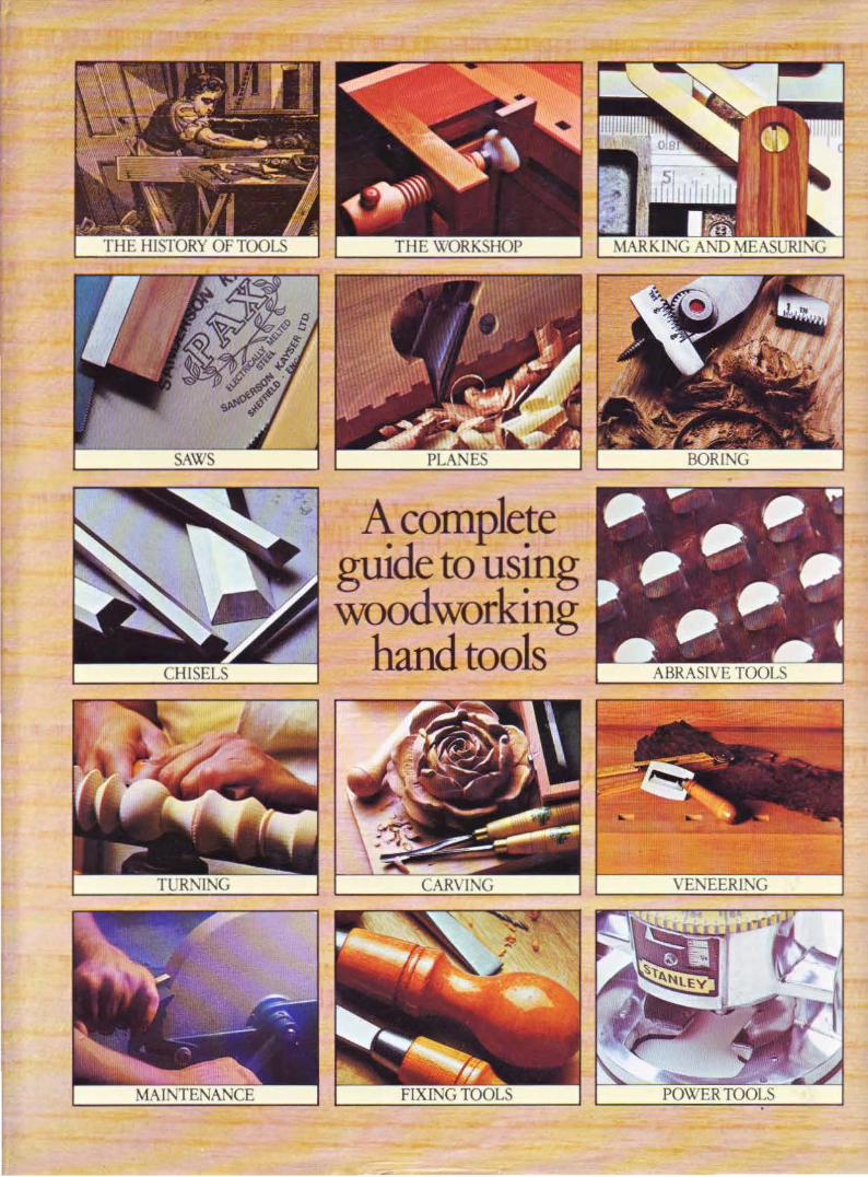
"' A complete guide to using woodworking
hand tools