gas density measurement for self- modulation eperiment...
TRANSCRIPT

Gas Density Measurement for Self-modulation Eperiment at PITZ
G. Pathak1, M. Gross2, F. Stephan2
1 Universität Hamburg, Luruper Chaussee 149, 22761 Hamburg, Germany 2 DESY, Zeuthen Site, Platanenallee 6, 15738 Zeuthen, Germany
DPG Spring meeting 09-13 March, 2015
> Self-Modulation
> Methods of gas density measurement
> Progress in gas density measurement
> Summary
Gaurav Pathak | 10 March 2015 | Page 2
Self-modulation
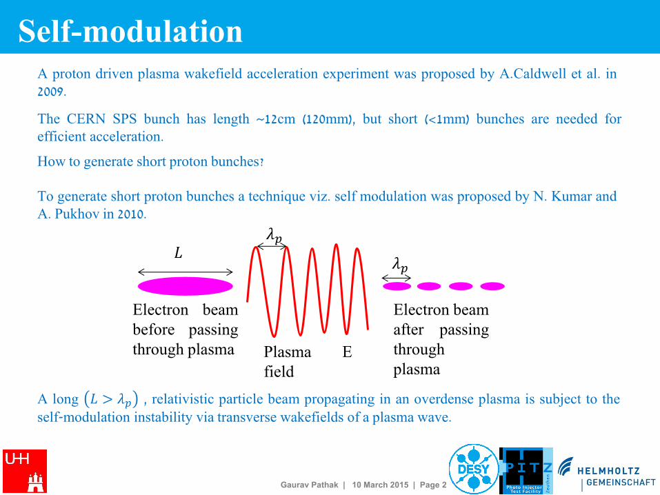
A long 𝐿 > 𝜆𝑝 , relativistic particle beam propagating in an overdense plasma is subject to the self-modulation instability via transverse wakefields of a plasma wave.
Electron beam before passing through plasma
Electron beam after passing through plasma
Plasma E field
𝜆𝑝
𝜆𝑝 𝐿
A proton driven plasma wakefield acceleration experiment was proposed by A.Caldwell et al. in 2009.
The CERN SPS bunch has length ~12cm (120mm), but short (<1mm) bunches are needed for efficient acceleration.
How to generate short proton bunches?
To generate short proton bunches a technique viz. self modulation was proposed by N. Kumar and A. Pukhov in 2010.

Gaurav Pathak | 10 March 2015 | Page 3
Self-modulation can be applied to long electron bunches, too.
Because of its very favorable experimental conditions, a preparatory experiment was proposed to set up a plasma cell in the PITZ (Photo-Injector Test facility at DESY, Zeuthen site) beam line to study the self-modulation of electron beams when they pass through laser generated lithium plasma.
Thermal
Insulation Cooling
Sleeve
Electron
Window
Helium
Distribution
Heating Coils
e-
Ionization
Laser Path Laser
Window
Design:
Gerald Koss
Fabricated Cell Li Gas
1015 cm-3
Self-modulation at PITZ
Gaurav Pathak | 10 March 2015 | Page 4
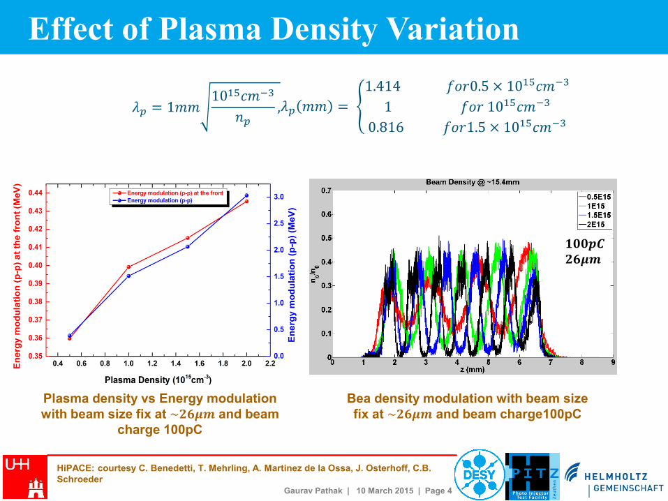
Effect of Plasma Density Variation
𝟏𝟎𝟎𝒑𝑪 𝟐𝟔𝝁𝒎
Plasma density vs Energy modulation
with beam size fix at ~𝟐𝟔𝝁𝒎 and beam
charge 100pC
Bea density modulation with beam size
fix at ~𝟐𝟔𝝁𝒎 and beam charge100pC
HiPACE: courtesy C. Benedetti, T. Mehrling, A. Martinez de la Ossa, J. Osterhoff, C.B.
Schroeder
𝜆𝑝 = 1𝑚𝑚1015𝑐𝑚−3
𝑛𝑝, 𝜆𝑝 𝑚𝑚 =
1.414 𝑓𝑜𝑟0.5 × 10¹⁵𝑐𝑚−3
1 𝑓𝑜𝑟 1015𝑐𝑚−3
0.816 𝑓𝑜𝑟1.5 × 10¹⁵𝑐𝑚−3
Gaurav Pathak | 10 March 2015 | Page 5
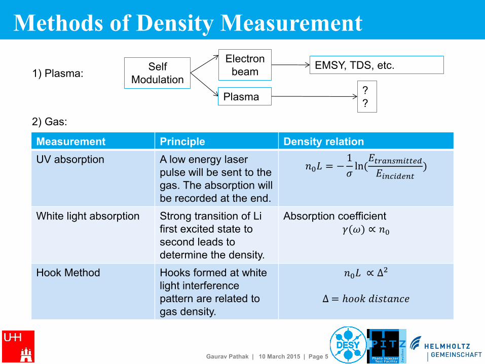
Methods of Density Measurement
Measurement Principle Density relation
UV absorption A low energy laser
pulse will be sent to the
gas. The absorption will
be recorded at the end.
𝑛0𝐿 = −1
𝜎ln (
𝐸𝑡𝑟𝑎𝑛𝑠𝑚𝑖𝑡𝑡𝑒𝑑
𝐸𝑖𝑛𝑐𝑖𝑑𝑒𝑛𝑡)
White light absorption Strong transition of Li
first excited state to
second leads to
determine the density.
Absorption coefficient
𝛾(𝜔) ∝ 𝑛0
Hook Method Hooks formed at white
light interference
pattern are related to
gas density.
𝑛0𝐿 ∝ ∆2
∆ = ℎ𝑜𝑜𝑘 𝑑𝑖𝑠𝑡𝑎𝑛𝑐𝑒
Self
Modulation
Electron
beam
Plasma
EMSY, TDS, etc.
?
?
1) Plasma:
2) Gas:
Gaurav Pathak | 10 March 2015 | Page 6
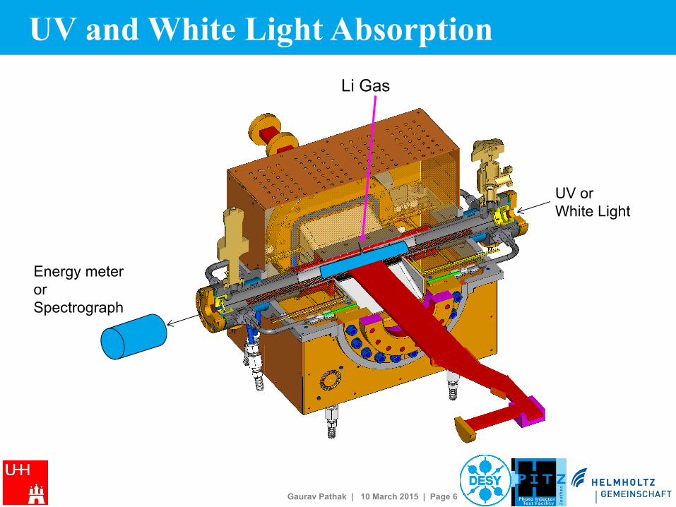
UV and White Light Absorption
Li Gas
UV or
White Light
Energy meter
or
Spectrograph
Gaurav Pathak | 10 March 2015 | Page 7
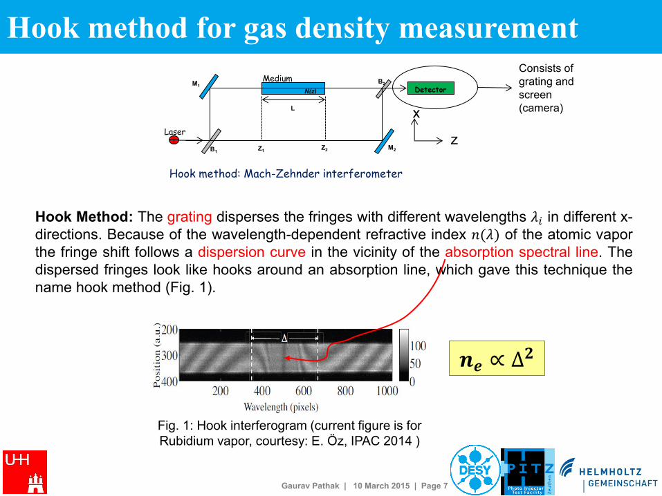
Hook Method: The grating disperses the fringes with different wavelengths 𝜆𝑖 in different x-
directions. Because of the wavelength-dependent refractive index 𝑛(𝜆) of the atomic vapor
the fringe shift follows a dispersion curve in the vicinity of the absorption spectral line. The
dispersed fringes look like hooks around an absorption line, which gave this technique the
name hook method (Fig. 1).
Consists of
grating and
screen
(camera)
Detector
L
M1
B1
B2
M2 Z1 Z2
Laser
N(z)
Medium
Hook method: Mach-Zehnder interferometer
x
z
𝒏𝒆 ∝ ∆𝟐
Hook method for gas density measurement
Fig. 1: Hook interferogram (current figure is for
Rubidium vapor, courtesy: E. Öz, IPAC 2014 )
Gaurav Pathak | 10 March 2015 | Page 8
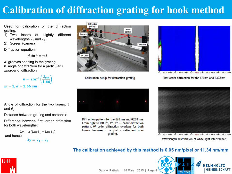
The calibration achieved by this method is 0.05 nm/pixel or 11.34 nm/mm
Used for calibration of the diffraction
grating:
1) Two lasers of slightly different
wavelengths 𝜆1 and 𝜆2.
2) Screen (camera).
Diffraction equation:
𝑑 sin 𝜃 = 𝑚𝜆
𝑑: grooves spacing in the grating
θ: angle of diffraction for a particular 𝜆 𝑚:order of diffraction
𝜽 = 𝒔𝒊𝒏−𝟏𝝀𝝁𝒎
𝟏. 𝟔𝟔
𝒎 = 𝟏, 𝒅 = 𝟏. 𝟔𝟔 𝝁𝒎
Angle of diffraction for the two lasers: 𝜃1
and 𝜃2
Distance between grating and screen: 𝑥
Difference between first order diffraction
for both wavelengths:
Δ𝑦 = 𝑥(tan 𝜃1 − tan 𝜃2) and hence
𝜟𝒚 = 𝝀𝟏 − 𝝀𝟐
Calibration of diffraction grating for hook method
Gaurav Pathak | 10 March 2015 | Page 9
Summary
• Lithium gas density for PITZ plasma experiment will be measured with
Hook method.
• Calibration has been done for diffraction grating using two lasers and it
comes out to be 0.05 nm/pixel or 11.34 nm/mm.
• Expected gas density: ~1015𝑐𝑚−3 - can be measured with this method.
• Plasma density will be measured by different methods as well.

Gaurav Pathak | 10 March 2015 | Page 10
Back up for simulations

Gaurav Pathak | 10 March 2015 | Page 11
Beam properties before plasma
𝑥′ = 1.6𝑚𝑟𝑎𝑑
𝑦′ = 1.6𝑚𝑟𝑎𝑑
𝑃𝑧𝑚𝑒𝑎𝑛 = 22𝑀𝑒𝑉/𝑐 𝑃𝑧𝑟𝑚𝑠 = 22𝑀𝑒𝑉/𝑐
𝑥𝑟𝑚𝑠 = 27𝜇𝑚
𝑦𝑟𝑚𝑠 = 26𝜇𝑚
𝜀𝑥 = 0.370𝑚𝑚 𝑚𝑟𝑎𝑑
𝜀𝑦 = 0.375𝑚𝑚 𝑚𝑟𝑎𝑑
Gaurav Pathak | 10 March 2015 | Page 12
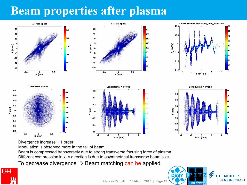
Beam properties after plasma
Divergence increase ~ 1 order
Modulation is observed more in the tail of beam.
Beam is compressed transversely due to strong transverse focusing force of plasma.
Different compression in x, y direction is due to asymmetrical transverse beam size.
To decrease divergence Beam matching can be applied
Gaurav Pathak | 10 March 2015 | Page 13
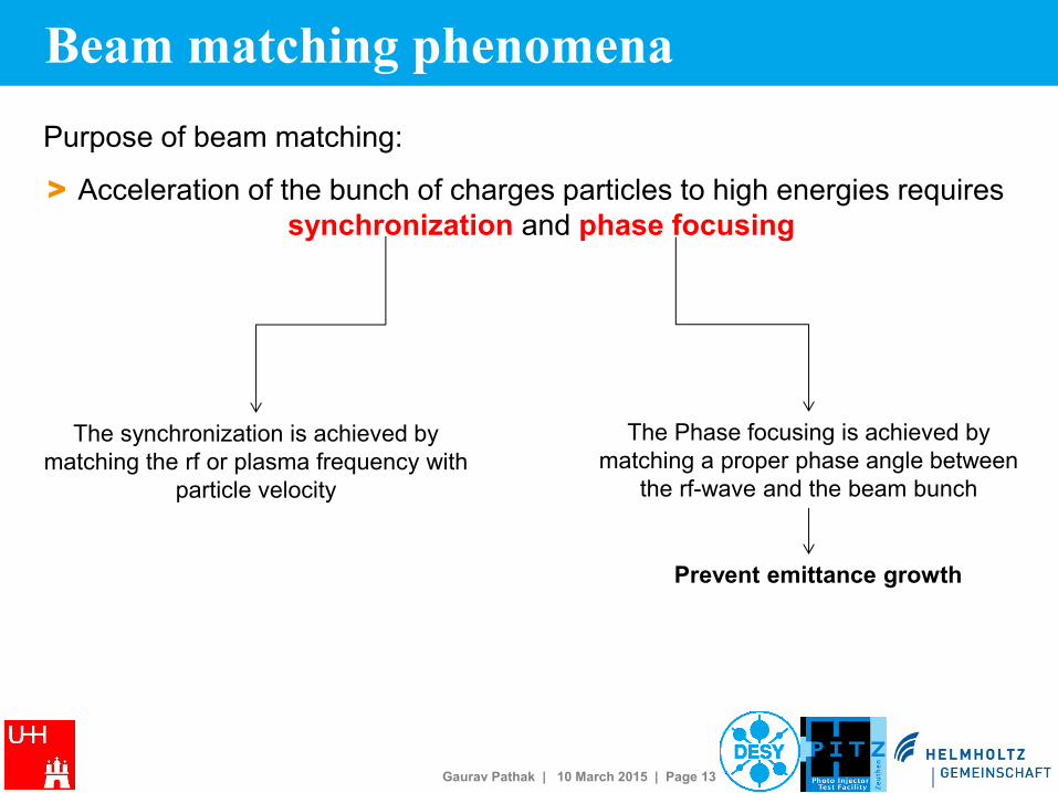
Beam matching phenomena
Purpose of beam matching:
> Acceleration of the bunch of charges particles to high energies requires
synchronization and phase focusing
The synchronization is achieved by
matching the rf or plasma frequency with
particle velocity
The Phase focusing is achieved by
matching a proper phase angle between
the rf-wave and the beam bunch
Prevent emittance growth
Gaurav Pathak | 10 March 2015 | Page 14
Beam matching for plasma accelerators Accelerating
+
Focusing accelerating
+
defocusing
decelerating
+
defocusing decelerating
+
focusing
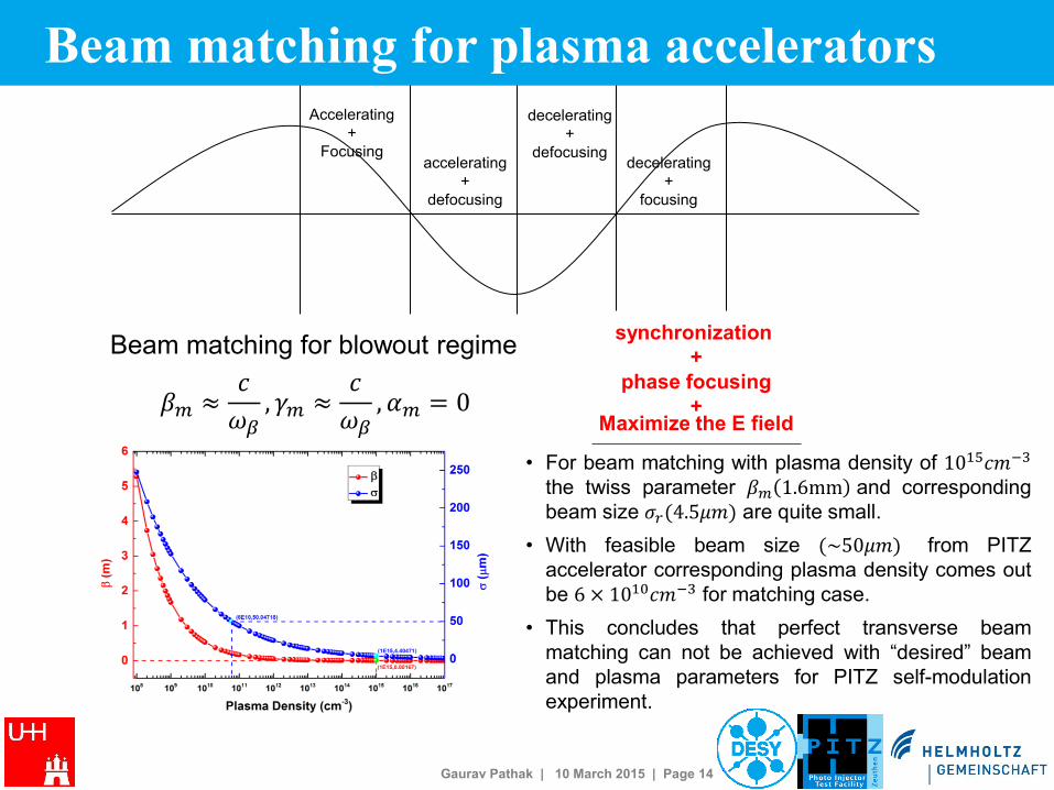
𝛽𝑚 ≈𝑐
𝜔𝛽, 𝛾𝑚 ≈
𝑐
𝜔𝛽, 𝛼𝑚 = 0
Beam matching for blowout regime synchronization
+
phase focusing
+ Maximize the E field
• For beam matching with plasma density of 1015𝑐𝑚−3
the twiss parameter 𝛽𝑚 1.6mm and corresponding
beam size 𝜎𝑟(4.5𝜇𝑚) are quite small.
• With feasible beam size (~50𝜇𝑚) from PITZ
accelerator corresponding plasma density comes out
be 6 × 10¹⁰𝑐𝑚−3 for matching case.
• This concludes that perfect transverse beam
matching can not be achieved with “desired” beam
and plasma parameters for PITZ self-modulation
experiment.
Gaurav Pathak | 10 March 2015 | Page 15
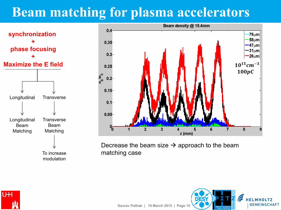
Beam matching for plasma accelerators
synchronization
+
phase focusing
+
Maximize the E field
Transverse Longitudinal
Transverse
Beam
Matching
Longitudinal
Beam
Matching
To increase
modulation
Decrease the beam size approach to the beam
matching case
𝟏𝟎𝟏𝟓𝒄𝒎−𝟑
𝟏𝟎𝟎𝒑𝑪

Gaurav Pathak | 10 March 2015 | Page 16
Beam density modulation
𝟏𝟎𝟏𝟓𝒄𝒎−𝟑
𝟏𝟎𝟎𝒑𝑪 𝟏𝟎𝟏𝟓𝒄𝒎−𝟑
𝟐𝟔𝝁𝒎
𝟏𝟎𝟎𝒑𝑪 𝟐𝟔𝝁𝒎

Gaurav Pathak | 10 March 2015 | Page 17
Longitudinal wakefield
𝐸𝑧 ∝𝑛𝑏0
𝑛𝑝. 𝑅(0)
𝐸𝑓𝑜𝑐𝑢𝑠 ∝𝑛𝑏0
𝑛𝑝𝑅′(𝜎𝑟)
𝟏𝟎𝟏𝟓𝒄𝒎−𝟑
𝟏𝟎𝟎𝒑𝑪
Where 𝑅(0) is the unitless transverse component.
Both 𝑅(0) and 𝑅′ are increasing function of 𝑘𝑝𝜎𝑟 .
Plasma focusing for high energy beams – P.Chen,
IEEE,1986
𝟐𝟔𝝁𝒎
𝟏𝟎𝟎𝒑𝑪
Gaurav Pathak | 10 March 2015 | Page 18
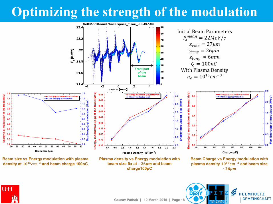
Optimizing the strength of the modulation
Initial Beam Parameters 𝑃𝑧𝑚𝑒𝑎𝑛 = 22𝑀𝑒𝑉/𝑐 𝑥𝑟𝑚𝑠 = 27𝜇𝑚
𝑦𝑟𝑚𝑠 = 26𝜇𝑚 𝑧𝑙𝑜𝑛𝑔 ≈ 6𝑚𝑚
𝑄 = 100𝑛𝐶 With Plasma Density 𝑛𝑒 = 1015𝑐𝑚−3
Front part
of the
beam
Beam size vs Energy modulation with plasma
density at 𝟏𝟎𝟏𝟓𝒄𝒎−𝟑 and beam charge 100pC
Plasma density vs Energy modulation with
beam size fix at ~𝟐𝟔𝝁𝒎 and beam
charge100pC
Beam Charge vs Energy modulation with
plasma density 𝟏𝟎𝟏𝟓𝒄𝒎−𝟑 and beam size
~𝟐𝟔𝝁𝒎