gas-fired high and low intensity infrared heaters
TRANSCRIPT
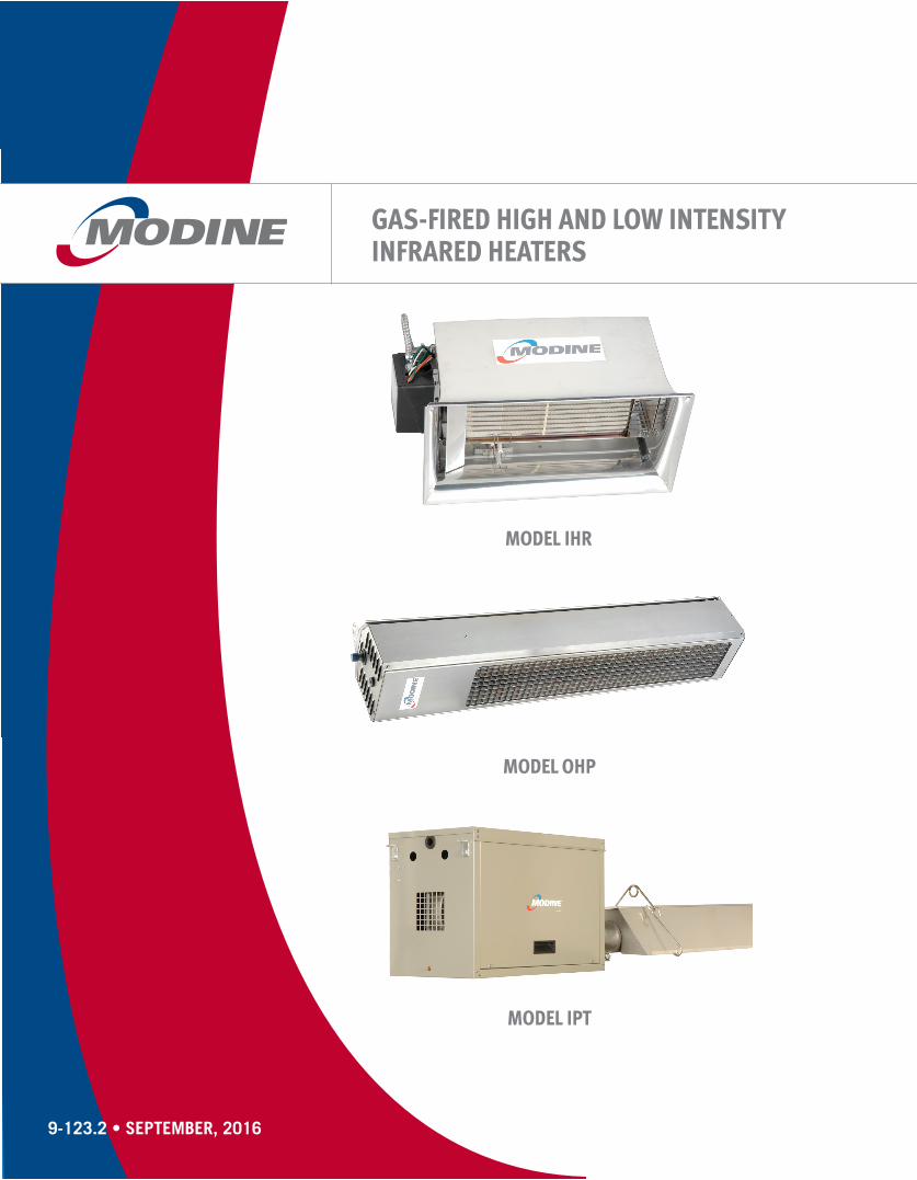
GAS-FIRED HIGH AND LOW INTENSITYINFRARED HEATERS
MODEL IPT
MODEL IHR
9-123.2 • SEPTEMBER, 2016
MODEL OHP

2 9-123.2
39-123.2
TABLE OF CONTENTS
This catalog describes the design and construction features and benefits, typical applications, dimensional data, and configurations available for the IHR and ITP Series. Modine’s IHR Series is a gas-fired, high intensity ceramic infrared heater. Ideal for spot heating, the IHR series offers simple gas and power connections, as well as inexpensive maintenance.Modine's IPT Series sets the industry standard for low intensity infrared heating performance and installation versatility. The comfort and uniform heating provided by the IPT Series are second to none.
Refer to page 3 for information regarding the Breeze® AccuSpec Sizing and Selection Program
WARNINGDo not locate ANY gas-fired unit in areas where chlorinated, halogenated or acid vapors are present in the atmosphere.
WARNINGDo not install in potentially explosive or flammable atmosphere laden with dust, sawdust, or similar airborne materials.
As Modine Manufacturing Company has a continuous product improvement program, it reserves the right to change design and specifications without notice.
Table of Contents
General Unit Applications .......................................................... 2 Infrared Heating Defined ....................................................... 2 Advantages of Infrared Heating ............................................ 2 Typical Applications ............................................................... 2Modine Breeze® AccuSpec Sizing and Selection Program ........ 3Features and Benefits - Model IHR ............................................ 4Features and Benefits - Model IHR ............................................ 5Features and Benefits - Model IPT ............................................ 6Performance and Dimensional Data - Model IHR ................... 7-8Performance and Dimensional Data - Model OHP .................... 9Performance, Utilities, and Clearance - Model IPT .................. 10Dimensional Data - Model IPT ................................................. 11Specifications and Model Nomenclature - Model IHR ............. 12Specifications and Model Nomenclature - Model IPT .............. 13
Infrared Heating DefinedInfrared heating systems rely upon the transfer of radiant energy from hot heat exchanger surfaces (up to 1850°F for high intensity heaters) through the air to cooler surfaces, without the use of an air mover. Since radiant energy always travels in a straight line from its source, people and objects within a direct line-of-sight of the heat exchanger become warmed immediately.
While capable of being used for total building heating or large area heating, they are ideally suited for spot heating applications. Spot heating involves small areas such as loading dock doors and single person work cells.
Advantages of Infrared Heating No air mover, reducing electricity and maintenance costs
while increasing worker comfort from the absence of drafts and annoying fan noise.
Quick temperature recovery, as only objects need to be heated, not large volumes of air.
Significant energy savings through use of zone control and/or spot heating, which heats objects without the need to heat large air volumes.
Typical ApplicationsThe following are examples of applications that can benefit from high-intensity infrared heating: Manufacturing facilities Vehicle repair centers Warehouses and loading docks Aircraft hangars Indoor tennis courts Indoor golf driving ranges Emergency vehicle garages Indoor stadium seating areas
The following are examples of applications that can benefit from low-intensity infrared heating: Manufacturing facilities Vehicle repair centers Warehouses and loading docks Aircraft hangars Tennis courts Car washes Golf driving ranges Covered walkways Emergency vehicle garages Stadium seating areas Vestibules
See Infrared Design and Engineering Guide 9-200 for additional application information.
!!
4 9-123.2
MODINE BREEZE® ACCUSPEC SIZING & SELECTION PROGRAM
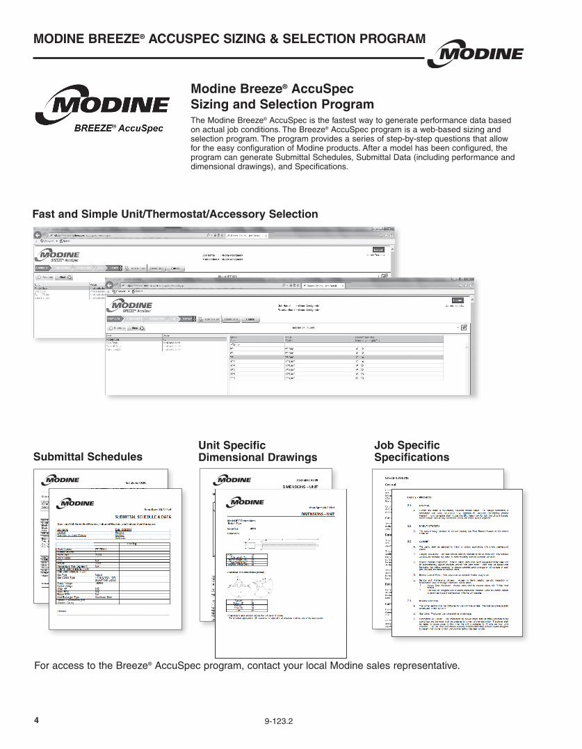
Modine Breeze® AccuSpecSizing and Selection ProgramThe Modine Breeze® AccuSpec is the fastest way to generate performance data based on actual job conditions. The Breeze® AccuSpec program is a web-based sizing and selection program. The program provides a series of step-by-step questions that allow for the easy configuration of Modine products. After a model has been configured, the program can generate Submittal Schedules, Submittal Data (including performance and dimensional drawings), and Specifications.
Fast and Simple Unit/Thermostat/Accessory Selection
Submittal SchedulesJob Specific Specifications
Unit Specific Dimensional Drawings
For access to the Breeze® AccuSpec program, contact your local Modine sales representative.
59-123.2
FEATURES AND BENEFITS - MODEL IHR
Features
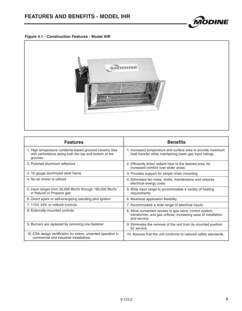
1. High temperature cordierite-based grooved ceramic tiles with perforations along both the top and bottom of the grooves
2. Polished aluminum reflectors
3. 16 gauge aluminized steel frame
4. No air mover is utilized
5. Input ranges from 30,000 Btu/hr through 160,000 Btu/hr in Natural or Propane gas
6. Direct spark or self-energizing standing pilot ignition
7. 115V, 25V, or millivolt controls
8. Externally-mounted controls
9. Burners are replaced by removing one fastener
10. CSA design certification for indoor, unvented operation in commercial and industrial installations
Figure 4.1 - Construction Features - Model IHR
Benefits
1. Increased temperature and surface area to provide maximum heat transfer while maintaining lower gas input ratings.
2. Efficiently direct radiant heat to the desired area, for increased comfort over wider areas.
3. Provides support for simple chain mounting.
4. Eliminates fan noise, drafts, maintenance and reduces electrical energy costs.
5. Wide input range to accommodate a variety of heating requirements
6. Maximize application flexibility.
7. Accommodate a wide range of electrical inputs.
8. Allow convenient access to gas valve, control system, transformer, and gas orifices, increasing ease of installation and service.
9. Eliminates the removal of the unit from its mounted position for service.
10. Assures that the unit conforms to national safety standards.

6 9-123.2
FEATURES AND BENEFITS - MODEL OHP
Features
1.ETL Design Certified to ANSI Z83.26 Standard
2. Decorative stainless steel windscreen eggcrate grille
3. Wind and rain protected design
4. 31,000 and 34,000 BTU inputs. Natural or propane gas
5. No Fan Design.
6. Externally-mounted controls
7. Direct spark or self-energizing standing pilot ignition
8. Brushed 430 Stainless Steel Housing
Figure 5.1 - Construction Features - Model OHP
Benefits
1. Assures that the unit conforms to national safety standards.
2. Prevents wind disturbance.
3. Input range to accommodate a variety of heating requirements.
4. Flexible fuel type offering.
5.Eliminates fan noise, drafts, maintenance and reduces electrical energy costs.
6. Allow convenient access to gas valve, control system, transformer, and gas orifices, increasing ease of installation and service.
7. Maximize application flexibility.
8. Provides maximum corrosion resistance.
79-123.2
FEATURES AND BENEFITS - MODEL IPT
Features
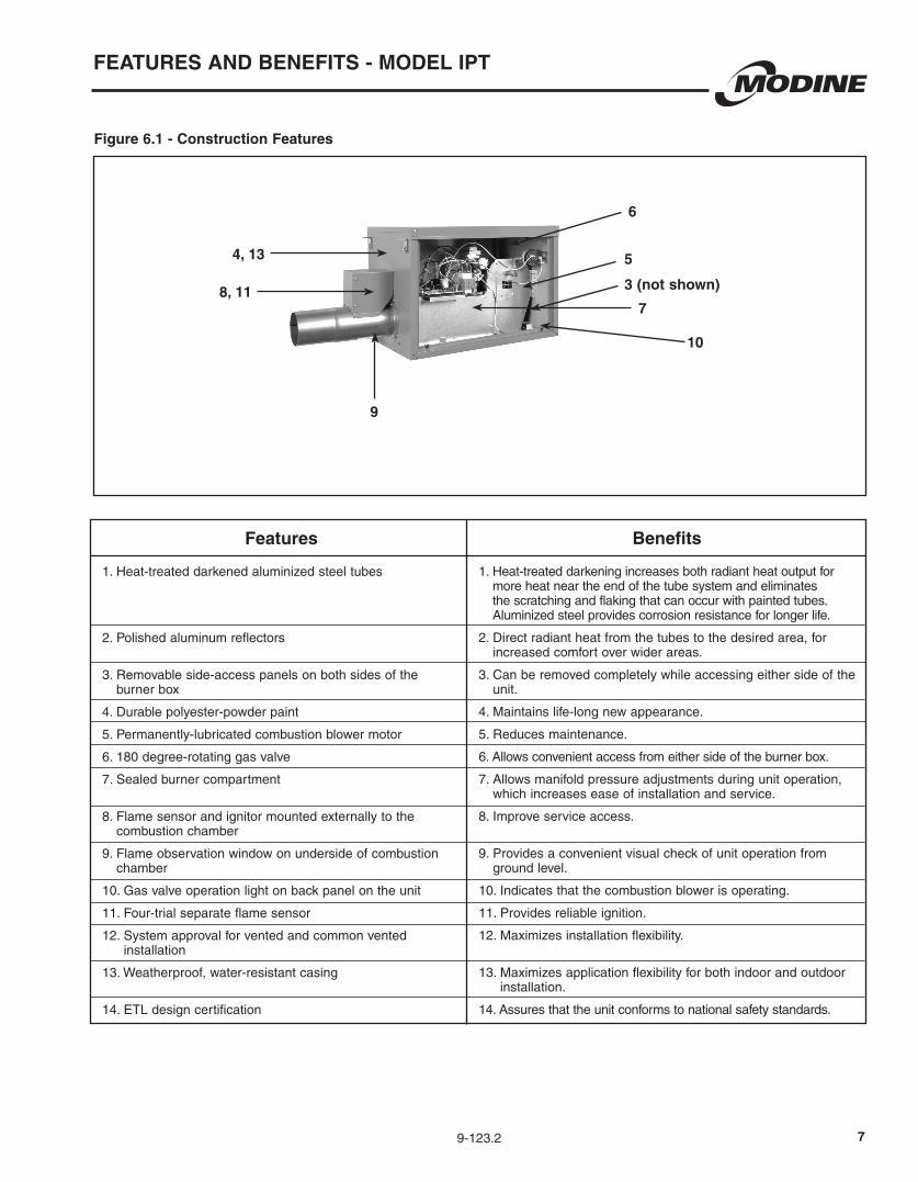
1. Heat-treated darkened aluminized steel tubes
2. Polished aluminum reflectors
3. Removable side-access panels on both sides of the burner box
4. Durable polyester-powder paint
5. Permanently-lubricated combustion blower motor
6. 180 degree-rotating gas valve
7. Sealed burner compartment
8. Flame sensor and ignitor mounted externally to the combustion chamber
9. Flame observation window on underside of combustion chamber
10. Gas valve operation light on back panel on the unit
11. Four-trial separate flame sensor
12. System approval for vented and common vented installation
13. Weatherproof, water-resistant casing
14. ETL design certification
Figure 6.1 - Construction Features
4, 13
8, 11
9
10
3 (not shown)
5
6
Benefits
1. Heat-treated darkening increases both radiant heat output for more heat near the end of the tube system and eliminates the scratching and flaking that can occur with painted tubes. Aluminized steel provides corrosion resistance for longer life.
2. Direct radiant heat from the tubes to the desired area, for increased comfort over wider areas.
3. Can be removed completely while accessing either side of the unit.
4. Maintains life-long new appearance.
5. Reduces maintenance.
6. Allows convenient access from either side of the burner box.
7. Allows manifold pressure adjustments during unit operation, which increases ease of installation and service.
8. Improve service access.
9. Provides a convenient visual check of unit operation from ground level.
10. Indicates that the combustion blower is operating.
11. Provides reliable ignition.
12. Maximizes installation flexibility.
13. Maximizes application flexibility for both indoor and outdoor installation.
14. Assures that the unit conforms to national safety standards.
7
9-123.2
PERFORMANCE AND DIMENSIONAL DATA - MODEL IHR
8
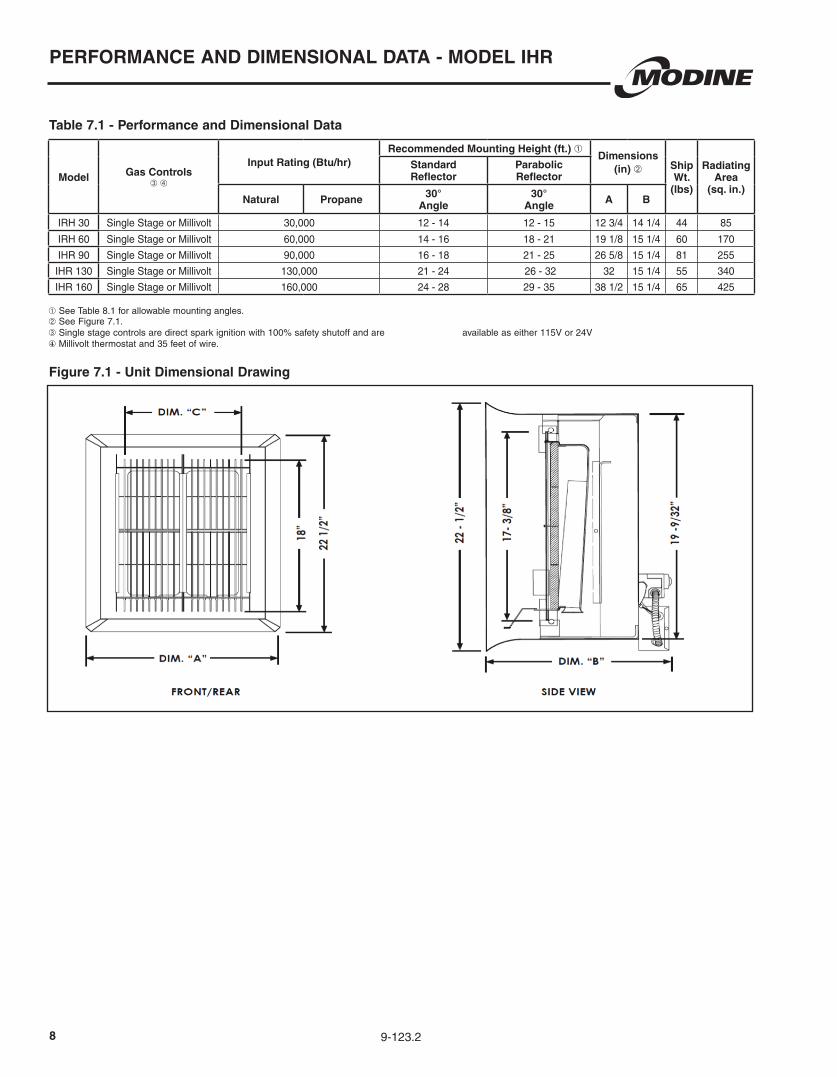
Table 7.1 - Performance and Dimensional Data
➀ See Table 8.1 for allowable mounting angles.➁ See Figure 7.1.➂ Single stage controls are direct spark ignition with 100% safety shutoff and are available as either 115V or 24V④ Millivolt thermostat and 35 feet of wire.
Figure 7.1 - Unit Dimensional Drawing
Model Gas Controls ➂ ➃
Input Rating (Btu/hr)Recommended Mounting Height (ft.) ➀
Dimensions (in) ➁ Ship
Wt.(lbs)
Radiating Area
(sq. in.)
Standard Reflector
Parabolic Reflector
Natural Propane 30° Angle
30° Angle A B
IRH 30 Single Stage or Millivolt 30,000 12 - 14 12 - 15 12 3/4 14 1/4 44 85
IRH 60 Single Stage or Millivolt 60,000 14 - 16 18 - 21 19 1/8 15 1/4 60 170
IHR 90 Single Stage or Millivolt 90,000 16 - 18 21 - 25 26 5/8 15 1/4 81 255
IHR 130 Single Stage or Millivolt 130,000 21 - 24 26 - 32 32 15 1/4 55 340
IHR 160 Single Stage or Millivolt 160,000 24 - 28 29 - 35 38 1/2 15 1/4 65 425
9-123.2
PERFORMANCE AND DIMENSIONAL DATA - MODEL IHR
9
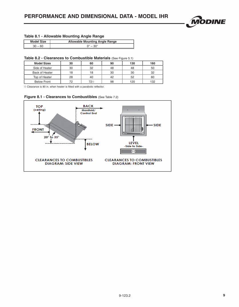
Table 8.1 - Allowable Mounting Angle Range Model Size Allowable Mounting Angle Range
30 – 60 0° – 30°
Table 8.2 - Clearances to Combustible Materials (See Figure 5.1)
Figure 8.1 - Clearances to Combustibles (See Table 7.2)
➀ Clearance is 80 in. when heater is fitted with a parabolic reflector.
Model Sizes 30 60 90 130 160
Side of Heater 30 32 48 48 50
Back of Heater 18 18 30 30 32
Top of Heater 28 40 42 52 60
Below Front 72 72➀ 98 120 132
10 9-123.2
PERFORMANCE AND DIMENSIONAL DATA - MODEL OHP
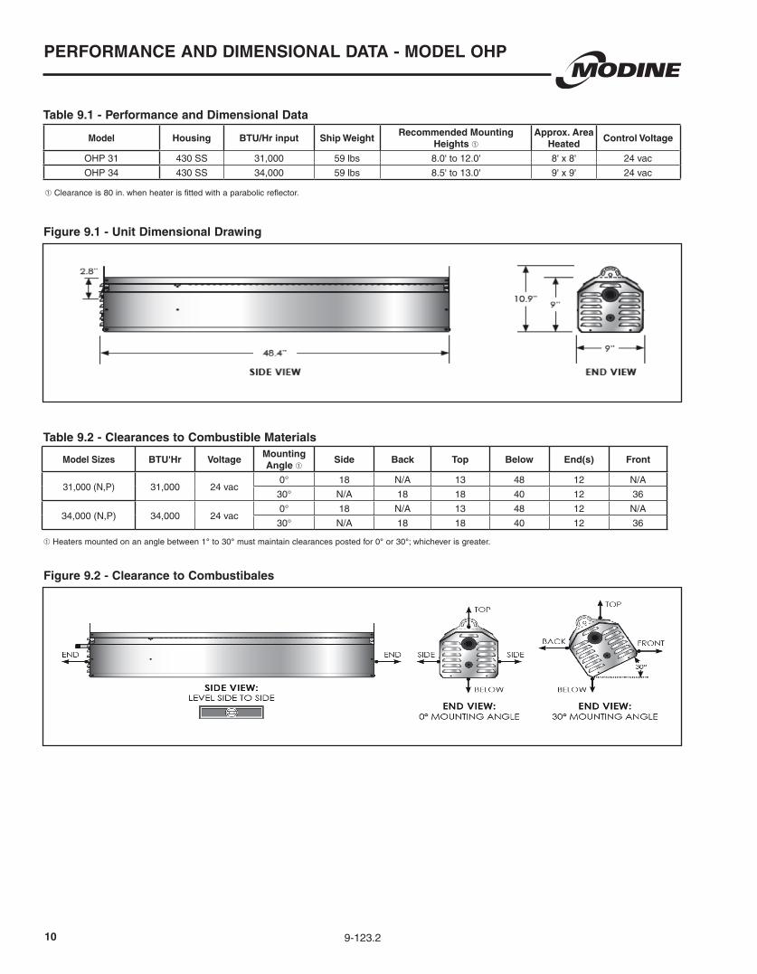
Table 9.1 - Performance and Dimensional Data
Table 9.2 - Clearances to Combustible Materials
Figure 9.1 - Unit Dimensional Drawing
➀ Clearance is 80 in. when heater is fitted with a parabolic reflector.
Model Housing BTU/Hr input Ship WeightRecommended Mounting
Heights ➀Approx. Area
HeatedControl Voltage
OHP 31 430 SS 31,000 59 lbs 8.0' to 12.0' 8' x 8' 24 vac
OHP 34 430 SS 34,000 59 lbs 8.5' to 13.0' 9' x 9' 24 vac
Model Sizes BTU'Hr VoltageMounting Angle ➀
Side Back Top Below End(s) Front
31,000 (N,P) 31,000 24 vac0° 18 N/A 13 48 12 N/A
30° N/A 18 18 40 12 36
34,000 (N,P) 34,000 24 vac0° 18 N/A 13 48 12 N/A
30° N/A 18 18 40 12 36
➀ Heaters mounted on an angle between 1° to 30° must maintain clearances posted for 0° or 30°; whichever is greater.
Figure 9.2 - Clearance to Combustibales
119-123.2
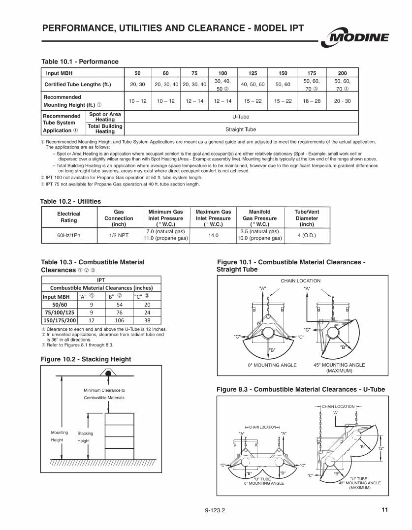
Mounting
Height
Minimum Clearance to
Combustible Materials
Stacking
Height
Figure 10.2 - Stacking Height
Electrical Gas Minimum Gas Maximum Gas Manifold Tube/Vent Rating Connection Inlet Pressure Inlet Pressure Gas Pressure Diameter (inch) (" W.C.) (" W.C.) (" W.C.) (inch)
60Hz/1Ph
1/2 NPT
7.0 (natural gas) 14.0
3.5 (natural gas) 4 (O.D.) 11.0 (propane gas) 10.0 (propane gas)
Table 10.2 - Utilities
➀ Clearance to each end and above the U-Tube is 12 inches.➁ In unvented applications, clearance from radiant tube end
is 36" in all directions.➂ Refer to Figures 8.1 through 8.3.
Table 10.3 - Combustible Material Clearances ➀ ➁ ➂
"U" TUBE
"B"
"C"
"A"
"B"
"A"
0° MOUNTING ANGLE
"B"
"B"
"C""C"
"C"
"A"
"C"
"C"
"B"
"B""U" TUBE
CHAIN LOCATION
CHAIN LOCATION
CHAIN LOCATION
45° MOUNTING ANGLE(MAXIMUM)
0° MOUNTING ANGLE
12"
45° MOUNTING ANGLE(MAXIMUM)
"A"
"A"
Figure 10.1 - Combustible Material Clearances - Straight Tube
"U" TUBE
"B"
"C"
"A"
"B"
"A"
0° MOUNTING ANGLE
"B"
"B"
"C""C"
"C"
"A"
"C"
"C"
"B"
"B""U" TUBE
CHAIN LOCATION
CHAIN LOCATION
CHAIN LOCATION
45° MOUNTING ANGLE(MAXIMUM)
0° MOUNTING ANGLE
12"
45° MOUNTING ANGLE(MAXIMUM)
"A"
"A"
Figure 8.3 - Combustible Material Clearances - U-Tube
PERFORMANCE, UTILITIES AND CLEARANCE - MODEL IPT
Table 10.1 - Performance
Input MBH 50 60 75 100 125 150 175 200
20, 30
20, 30, 40
20, 30, 40
30, 40, 40, 50, 60
50, 60
50, 60, 50, 60,
50 ➁ 70 ➂ 70 ➂
10 – 12 10 – 12 12 – 14 12 – 14 15 – 22 15 – 22 18 – 28 20 - 30
➀ Recommended Mounting Height and Tube System Applications are meant as a general guide and are adjusted to meet the requirements of the actual application. The applications are as follows:
-- Spot or Area Heating is an application where occupant comfort is the goal and occupant(s) are either relatively stationary (Spot - Example: small work cell or dispersed over a slightly wilder range than with Spot Heating (Area - Example: assembly line). Mounting height is typically at the low end of the range shown above.
-- Total Building Heating is an application where average space temperature is to be maintained, however due to the significant temperature gradient differences on long straight tube systems, areas may exist where direct occupant comfort is not achieved.
➁ IPT 100 not available for Propane Gas operation at 50 ft. tube system length.
➂ IPT 75 not available for Propane Gas operation at 40 ft. tube section length.
Certified Tube Lengths (ft.)
Recommended
Mounting Height (ft.) ➀
Recommended Tube System
Application ➀
U-Tube
Straight Tube
Spot or AreaHeating
Total BuildingHeating
Input MBH "A" 1 "B" 2 "C" 3
50/60 9 54 2075/100/125 9 76 24
150/175/200 12 106 38
Combustible Material Clearances (inches)IPT
➀ ➁ ➂
12 9-123.2
TOP VIEW
FRONT VIEWSIDE VIEW
BACK VIEW
12.39
12.00
1.362.61
6.00
4.00 4.00
O 1.000GAS CONNECTION
O .875THERMOSTAT CONNECTION
O .875LINE VOLTAGECONNECTION
10.00
23.12
21.91 11.00
13.5814.99
6.00
3.65
Straight Tube U-Tube System
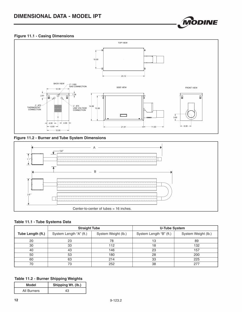
Tube Length (ft.) System Length “A” (ft.) System Weight (lb.) System Length “B” (ft.) System Weight (lb.) 20 23 78 13 89 30 33 112 18 132 40 43 146 23 157 50 53 180 28 200 60 63 214 33 225 70 73 252 38 277
Model Shipping Wt. (lb.)
All Burners 43
Table 11.2 - Burner Shipping Weights
Table 11.1 - Tube Systems Data
Figure 11.1 - Casing Dimensions
TOP VIEW
FRONT VIEWSIDE VIEW
BACK VIEW
12.39
12.00
1.362.61
6.00
4.00 4.00
O 1.000GAS CONNECTION
O .875THERMOSTAT CONNECTION
O .875LINE VOLTAGECONNECTION
10.00
23.12
21.91 11.00
13.5814.99
6.00
3.65
B
A
1 1 "
2 8 "
Center-to-center of tubes = 16 inches.
14"
Figure 11.2 - Burner and Tube System Dimensions
DIMENSIONAL DATA - MODEL IPT
139-123.2
GeneralThe heater reflector housing shall be constructed of one-side bright polished aluminum. The emitter shall be composed of a perforated ceramic tile on which combustion takes place on the surface. The burner plenum shall be constructed of aluminized steel of one-piece drawn construction. The heater shall beof a modular design employing multiple burners to achieve the specified input.
• The venturi is constructed of stainless or aluminized steel. • The secondary re-radiating rods shall be constructed of high temperature stainless steel alloy placed in close proximity of the ceramic burner face. • Parabolic reflectors shall be used when units are installed in high mounting applications or when focusing of the infrared heating pattern is desirable. • Protective screens shall be used in facilities where debris may damage the heater.
BurnerThe ceramic burner face shall operate at a temperature range of 1660 degrees F to 1810 degrees F and shall incorporate a secondary re-radiating surface of stainless steel rods to obtain optimum operating temperature and radiant output.
ReflectorsThe heater reflector housing shall be constructed of one-side bright polished aluminum. The emitter shall be composed of a perforated ceramic tile on which combustion takes place on the surface. The burner plenum shall be constructed of aluminized steel of one-piece drawn construction. The heater shall beof a modular design employing multiple burners to achieve the specified input.
• The venturi is constructed of stainless or aluminized steel. • The secondary re-radiating rods shall be constructed of high temperature stainless steel alloy placed in close proximity of the ceramic burner face. • Parabolic reflectors shall be used when units are installed in high mounting applications or when focusing of the infrared heating pattern is desirable. • Protective screens shall be used in facilities where debris may damage the heater.
ControlsHeater(s) shall be equipped with (check one):
• Heaters shall be equipped with one of the following control systems:
Standing Manual Pilot System with 100% safety shut-off of pilot and main burner in case of pilot outage, operating with no external electrical connection but on milli-voltage generated by the pilot flame (NMV-2 or PMV-2).
Direct Spark Ignition System with direct spark ignition
of the main burner through a solid state ignition module operating a spark electrode. Loss of power causes 100% safety shut-off of main burner(s). System operates on 120 or 24 volts (NFS-2 or PFS-2). 24V/60Hz/1ph with 6VA maximum power consumption.
Controls shall be exterior mounted for easy accessibility.
All controls shall be rated for a maximum inlet pressure of 1/2 PSI gas pressure. Controls shall be designed for Natural gas having a specific gravity of 0.60, a Btu content of 1050 Btu/ft3 (Alternate: Propane gas having a specific gravity of 1.53, a Btu content of 2500 Btu/ft3) at 0-2000 feet elevation.
AccessoriesThe following field installed accessories shall be included (check those that apply):
Chain mounting set - 5’ chain set with 4 “S” hooks. Preset mounting angle of 30°.
Horizontal parabolic reflector - Directs rays directly downward. Can be used for matching horizontal mounting specifications.
Full parabolic reflector - Directs rays in a more focused pattern. Typically used in high mounting applications.
Full parabolic reflector with screen - Directs rays in a more focused pattern. Outer screen protects ceramic grids from objects striking the heater.
DR heater screen - Screen slips on the outside of the reflectors and protects the ceramic grids.
Warning plaque - Hung below heater, restates the clearance to combustible warning.
SPECIFICATIONS, MODEL NOMENCLATURE - MODEL IHR
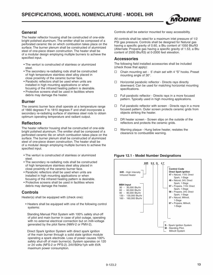
IHR - High Intensity Infrared Heater
MBH Input30 - 30,000 Btu/hr60 - 60,000 Btu/hr90 - 90,000 Btu/hr130 - 130,000 Btu/hr160 - 160,000 Btu/hr
Control Code Direct Spark Ignition47 = Natural, 115V, Direct
Spark, 1-Stage48 = Natural, 24V, Direct
Spark, 1-Stage97 = Propane, 115V, Direct
Spark, 1-Stage98 = Propane, 24V, Direct
Spark, 1-Stage27 = Natural, Millivolt,
1-Stage67 = Propane, Millivolt,
1-Stage
IHR 9 0 G 4 7
S - Spark Ignition SystemM - Standing Pilot, Milivolt System
Figure 12.1 - Model Number Designations
14 9-123.2
GeneralContractor shall furnish and install Modine model __________ low intensity infrared heater(s). The low intensity infrared system shall be straight tube________, U-tube_______ configuration. Performance shall be as indicated on the equipment schedule in the plans. The infrared heater(s) shall be certified for indoor and outdoor installations. Infrared heater(s) shall have ETL design certification for use in both the US and Canada.
CasingThe controls, combustion air blower and burner shall be housed in a water-resistant casing, providing weatherproof protection. The burner and control box casing shall be constructed of not less than 20 gauge aluminized steel. After forming, the casing parts shall be cleaned of all oils and a phosphate coating applied prior to painting. The phosphated parts shall then be finished with an electrostatically applied, gray-green polyester powder paint finish. The applied polyester powder paint shall be baked on to provide an attractive finish on all of the exposed casing parts.
Heat ExchangerThe heat exchanger tubes and combustion chamber shall be constructed of 16 gauge, 4" O. D. aluminized steel, and the first combustion tube for gas inputs 150,000 Btuh and greater shall be 16 gauge 4" O. D. 409 Aluminized Stainless Steel. The last heat exchanger tube shall incorporate a turbulator baffle for maximum efficiency of heat transfer.
The heat exchanger tubes must be used in conjunction with reflectors. The reflector can be adjusted from 0° to 45° from the horizontal plane. Reflectors shall be of bright polished aluminum.
ControlsInput power to the infrared heater(s) shall be 115V/60Hz/1ph. Heater(s) shall be equipped with a direct four-trial (three re-trial), 100% shut-off eletronic ignition control system with a separate flame sensor. Infrared heater(s) shall be equipped with a 115V/25V control transformer. Thermostat shall operate on 25V. Heater(s) will be equipped with a pre-purge mode, a differential pressure switch, and an indicator light to prove proper operation of the gas valve. All controls shall be rated for a maximum inlet pressure of 1/2 PSI gas pressure.
Controls shall be designed for natural_______, propane_______ gas having a specific gravity of _______, a Btu content of _______ Btu/ft3 at _______ feet elevation.
Motor Each heater shall have a single motor. The combustion air blower motor shall be totally enclosed in the control box and the motor shall be protected by a thermal overload switch. The motor shall be .03 H.P., 115 volt, 60 Hz, single phase, with an operating speed of 3000 rpm.
SPECIFICATIONS, MODEL NOMENCLATURE - MODEL IPT
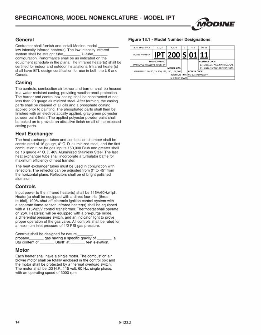
Figure 13.1 - Model Number Designations
SOLID EDGE
MODINE MANUFACTURING COMPANY1500 DE KOVEN AVENUERACINE, WISCONSIN 53403-2552
SERIAL PLATE MARKING SHEETIPT, LOW INTENSITY INFRARED
8H0075610000
1 1UNLESS OTHERWISE SPECIFIED: ALL DIMENSIONS ARE IN INCHES.
IN
AUTHOR
CAD MODEL NUMBER:
SURFACETEXTURE
MATERIALCORE CODE NUMBER
OFPAGE
1ST ANGLE
3RD ANGLE
NAMEDEPDATE
UNITS
FORMATSCALE
CAD SYSTEMSTANDARDAPPROVEDCHECKED
SIMILAR TO:
GENERAL TOLERANCE
REPLACES:
DESCRIPTION
DRAWING NUMBER
THIS PRINT AND ITS CONTENTS ARE THE PROPERTY OF MODINE AND MUST NOT BE USEDFOR ANY PURPOSE NOT AUTHORIZED BY MODINE. DO NOT DISCLOSE, REPRODUCE OROTHERWISE USE THIS PRINT OR ITS CONTENTS IN ANY MANNER DETRIMENTAL TO THEINTEREST OF MODINE WITHOUT MODINE'S PRIOR WRITTEN CONSENT. MODINE RESERVESALL RIGHTS OF DESIGN AND INVENTION TO THE EXTENT PERMITTED BY LAW.
A2
CPG aingle19Jun15CPG aingle28Feb14
28Feb14 CPG BRS
N/A N/A 8H0075610000.dft
UNLESS NOTED
2 PLC = u.03 3 PLC = u.005
ANGLES = u1v
DIS
TRIB
UTI
ON
:PL
OTT
ED :
8
E
D
A
B
C
H
G
F
H
G
F
E
A
B
C
D
121110987
1 2 3 4 5 6
1 2 3 4 5 6
7 12
BV7/
30/2
015
REVISION DESCRIPTION BY DATE CO NUMBER FIELD..... .
DIGIT SEQUENCE 1, 2, 3 4, 5, 6 7 8, 9 10, 11
MODEL NUMBER IPT 200 S 01 11
S: DIRECT SPARK
MODEL PREFIX: IMPROVED PRESSURE TUBE: IPT
MBH INPUT: 50, 60, 75, 100, 125, 150, 175, 200MODEL SIZE:
IGNITION TYPE:
11: SINGLE STAGE, NATURAL GAS21: SINGLE STAGE, PROPANE GAS
CONTROL CODE:
POWER CODE:01: 115V/60HZ/1PH
DIGIT SEQUENCE 1 2, 3 3, 4 5, 6 7, 8 9, 10 11, 12 13, 14, 15, 16 17, 18, 19, 20, 21
SERIAL NUMBER S 30 00 17 09 10 98 1234 10000
01: ROBERTSHAW, 09: WHITE ROGERS,
SPO MODELBLOWER MOTOR VENDOR CODE:
11: DAYTON 30: FASCO,
SPO NUMBERSEQUENTIAL NUMBERNUMBER VARIES FROM 0000 TO 9999.EACH UNIT WITHIN SAME WEEK OFMANUFACTURE IS TO HAVE UNIQUE NUMBER
YEAR OF MANUFACTUREUNIT SERIES:
00: ORIGINAL, 01: MODIFIEDCONTROL SUPPLIER:
05: HONEYWELL, 17: UNITED TECH, 08: FENWALGAS VALVE SUPPLIER:01: ROBERTSHAW, 05: HONEYWELL, 09: WHITE ROGERS
WEEK OF MANUFACTURESAME AS REQUIREMENTS PLANNING SHOP CALENDER

159-123.2
9-123.2
Products from Modine are designed to provide indoor air-comfort and ventilation solutions for residential, commercial, institutional and industrial applications. Whatever your heating, ventilating and air conditioning requirements, Modine has the product to satisfy your needs, including:
HVAC
• Unit Heaters:
– Gas
– Hydronic
– Electric
– Oil
• Ceiling Cassettes
• Duct Furnaces
• Hydronic Cabinet Unit Heaters, Fin Tube, Convectors
• Infrared Heaters
• Make-up Air Systems
• Unit Ventilators
Ventilation
• Packaged Rooftop Ventilation
School Products
• Vertical Packaged Classroom HVAC:
– DX Cooling/Heat Pump
– Water/Ground Source Heat Pump
– Horizontal/Vertical Unit Ventilators
Geothermal
• Water-to-Water
• Water-to-Air
• Combination Specific catalogs are available for each product. Catalogs 75-136 and 75-137 provide details on all Modine HVAC equipment.
Modine Manufacturing Company
1500 DeKoven AvenueRacine, Wisconsin 53403-2552Phone: 1.800.828.4328 (HEAT)www.modinehvac.com
© Modine Manufacturing Company 2016
The Modine brand has been the
industry standard since Arthur B.
Modine invented and patented
the first lightweight, suspended
hydronic unit heater in 1923.
No other manufacturer can
provide the combined application
flexibility, technical expertise and
fast delivery found at Modine.
Consult your local Modine
distributor for help in solving your
indoor air problems.