gas-fired hot water induced draft boilers · an iso 9001-2000 certified company r dunkirk boilers...
TRANSCRIPT

RAn ISO 9001-2000 Certified Company
DUNKIRK BOILERS85 Middle Rd.Dunkirk, NY 14048www.dunkirk.com
XEB SeriesGas-Fired Hot Water Induced Draft Boilers
INSTALLATION, OPERATION & MAINTENANCE MANUAL
P/N 14683001 Rev. B [11/09]
2
Tested for 50 lbs. ASME Working Pressure
HC.S.A. Certified for
Natural gas or Propane
The following defined symbols are used throughout this manual to notify the reader of potential hazards of varying risk levels.
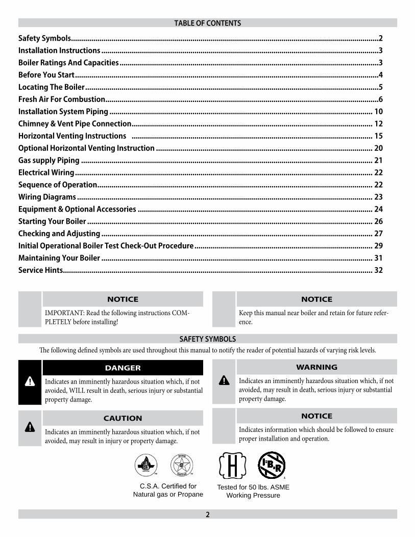
Safety Symbols........................................................................................................................................................2Installation Instructions .........................................................................................................................................3Boiler Ratings And Capacities ................................................................................................................................3Before You Start ......................................................................................................................................................4Locating The Boiler .................................................................................................................................................5Fresh Air For Combustion .......................................................................................................................................6Installation System Piping .................................................................................................................................. 10Chimney & Vent Pipe Connection ....................................................................................................................... 12Horizontal Venting Instructions ....................................................................................................................... 15Optional Horizontal Venting Instruction ........................................................................................................... 20Gas supply Piping ................................................................................................................................................ 21Electrical Wiring ................................................................................................................................................... 22Sequence of Operation ........................................................................................................................................ 22Wiring Diagrams .................................................................................................................................................. 23Equipment & Optional Accessories .................................................................................................................... 24Starting Your Boiler ............................................................................................................................................. 26Checking and Adjusting ...................................................................................................................................... 27Initial Operational Boiler Test Check-Out Procedure ........................................................................................ 29Maintaining Your Boiler ...................................................................................................................................... 31Service Hints......................................................................................................................................................... 32
TABLE OF CONTENTS
SAFETy SymBOLS
NOTICE
IMPORTANT: Read the following instructions COM-PLETELY before installing!
NOTICE
Keep this manual near boiler and retain for future refer-ence.
! DANGER
Indicates an imminently hazardous situation which, if not avoided, WILL result in death, serious injury or substantial property damage.
! WARNING
Indicates an imminently hazardous situation which, if not avoided, may result in death, serious injury or substantial property damage.
! CAUTION
Indicates an imminently hazardous situation which, if not avoided, may result in injury or property damage.
NOTICE
Indicates information which should be followed to ensure proper installation and operation.
3
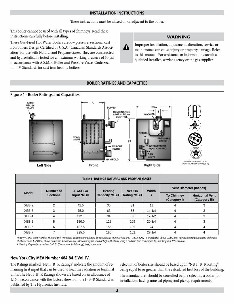
Table 1 -RATINGS NATURAL AND PROPANE GASES
Model Number of Sections
AGA/CGAInput *MBH
Heating Capacity *MBH+
Net IBR Rating *MBH
Width A
Vent Diameter (Inches)
To Chimney(Category I)
Horizontal Vent(Category III)
XEB-2 2 42.5 36 31 11 4 3XEB-3 3 75.0 63 55 14-1/4 4 3XEB-4 4 112.5 94 82 17-1/2 4 3XEB-5 5 150.0 125 109 20-3/4 4 3XEB-6 6 187.5 155 135 24 4 4XEB-7 7 225.0 186 162 27-1/4 4 4
* MBH = 1,000 Btuh = British Thermal Unit Per Hour. Boilers are equipped for altitudes up to 2,000 feet only. U.S.A. Only - For altitudes above 2,000 feet, ratings should be reduced at the rate of 4% for each 1,000 feet above sea level. Canada Only - Boilers may be used at high altitude by using a certified field conversion kit, resulting in a 10% de-rate.+ Heating Capacity based on D.O.E. (Department of Energy) test procedure.
DESIGN CERTIFIED FORNATURAL AND PROPANE GAS
H
This boiler cannot be used with all types of chimneys. Read these instructions carefully before installing.These Gas-Fired Hot Water Boilers are low pressure, sectional cast iron boilers Design Certified by C.S.A. (Canadian Standards Associ-ation) for use with Natural and Propane Gases. They are constructed and hydrostatically tested for a maximum working pressure of 50 psi in accordance with A.S.M.E. Boiler and Pressure Vessel Code Sec-tion IV Standards for cast iron heating boilers.
New york City mEA Number 484-84-E Vol. IV.The Ratings marked “Net I=B=R Ratings” indicate the amount of re-maining heat input that can be used to heat the radiation or terminal units. The Net I=B=R Ratings shown are based on an allowance of 1.15 in accordance with the factors shown on the I=B=R Standard as published by The Hydronics Institute.
Selection of boiler size should be based upon “Net I=B=R Rating” being equal to or greater than the calculated heat loss of the building.The manufacturer should be consulted before selecting a boiler for installations having unusual piping and pickup requirements.
INSTALLATION INSTruCTIONS
BOILEr rATINgS ANd CApACITIES
!
WARNING
Improper installation, adjustment, alteration, service or maintenance can cause injury or property damage. Refer to this manual. For assistance or information consult a qualified installer, service agency or the gas supplier.
Figure 1 - Boiler ratings and Capacities
These instructions must be affixed on or adjacent to the boiler.

4
Check to be sure you have the right size boiler before starting the installation. See rating and capacity table on previous page. Also be sure the new boiler is for the type of gas you are using. Check the rating plate on the right side of the boiler.Verify that the boiler is supplied with the correct type of gas, fresh air for combustion, and a suitable electrical supply. Also, the boiler must be connected to a suitable chimney or horizontal venting system and an adequate piping system. Finally, a thermostat, properly located, is needed for control of the heating system. If you have any doubts as to the various requirements, check with local authorities and obtain professional help where needed. Take the time to complete all of the steps for SAFE and PROPER operation of the heating system.If this boiler is installed in a building under construction, special care must be taken to insure a clean combustion air supply dur-ing the construction process. Airborne particulates such as from drywall dust and from fiberglass insulation can clog the burner ports and cause incomplete combustion and sooting. Where required by the authority having jurisdiction, the installation must conform to American Society of Mechanical Engineers Safety Code for Controls and Safety Devices for Automatically Fired Boilers, No. CSD-1.The installation must conform to the requirements of the authority having jurisdiction or, in the absence of such requirements, to the National Fuel Gas Code, ANSI Z223.1-latest revision.In Canada, the boiler shall be installed according to CSA-B149.1 and .2, Installation Code for Gas Burning Appliances and Equipment.
Boilers For use At High AltitudeThis boiler is factory equipped for use at altitudes of 0-2,000 feet above sea level. For use at altitudes above 2,000 feet above sea level, the input ratings are reduced by a change in main burner orifice size.
U.S.A. Only - For altitudes above 2,000 feet above sea level, input ratings should be reduced at the rate of 4% for each 1,000 feet above
These boilers must stand on a noncombustible floor. If installed on a combustible floor, please refer to the Repair Parts manual for the appropriate Combustible Floor Base part number. These Gas-Fired Hot Water Boilers are low pressure, sectional cast iron boilers Design Certified by CSA (Canadian Standards Associa-tion) for use with Natural and Propane Gases. They are constructed and hydrostatically tested for a maximum working pressure of 50psi (pounds per square inch) in accordance with A.S.M.E. (American Society of Mechanical Engineers) Boiler and Pressure Vessel Code Section IV Standards for cast iron heating boilers.
sea level. Consult the National Fuel Gas Code (NFPA54/ANSI Z223.1-latest revision), or the manufacturer for correct orifice siz-ing information. High altitude orifices are available from the boiler manufacturer.
Canada Only - For altitudes in the range of 2,000-4,500 feet above sea level, boilers may be field equipped for use at high altitude by using a certified field conversion kit. The change in main burner orifice size results in the boiler’s input rating being reduced by 10%.The conversion shall be carried out by a manufacturer’s authorized representative, in accordance with the requirements of the manufac-turer, provincial or territorial authorities having jurisdiction and in accordance with the requirements of the CSA-B149.1 and CSA-B149.2 Installation Codes. The certified field conversion kit includes a conversion data plate, which must be attached to the boiler adja-cent to the rating plate, indicating that the boiler has been converted for high altitude use. The conversion data plate must be filled in with the correct conversion information.
NOTICE
Installers - Follow local regulations with respect to instal-lation of CO detectors. Follow maintenance recommenda-tions in this instruction manual.
NOTICE
Keep boiler area clean and free from combustible materi-als, gasoline and other flammable vapors and liquids
BOILEr rATINgS & CApACITIES
BEFOrE yOu STArT
5
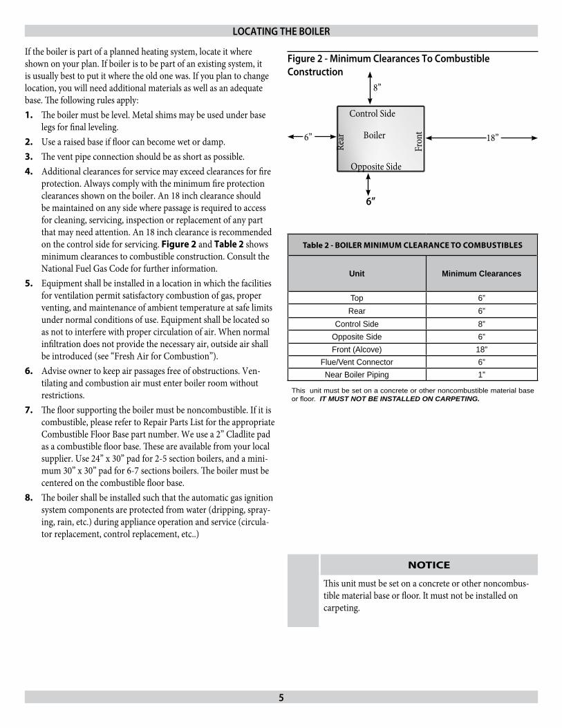
If the boiler is part of a planned heating system, locate it where shown on your plan. If boiler is to be part of an existing system, it is usually best to put it where the old one was. If you plan to change location, you will need additional materials as well as an adequate base. The following rules apply:
The boiler must be level. Metal shims may be used under base 1. legs for final leveling.Use a raised base if floor can become wet or damp.2. The vent pipe connection should be as short as possible.3. Additional clearances for service may exceed clearances for fire 4. protection. Always comply with the minimum fire protection clearances shown on the boiler. An 18 inch clearance should be maintained on any side where passage is required to access for cleaning, servicing, inspection or replacement of any part that may need attention. An 18 inch clearance is recommended on the control side for servicing. Figure 2 and Table 2 shows minimum clearances to combustible construction. Consult the National Fuel Gas Code for further information. Equipment shall be installed in a location in which the facilities 5. for ventilation permit satisfactory combustion of gas, proper venting, and maintenance of ambient temperature at safe limits under normal conditions of use. Equipment shall be located so as not to interfere with proper circulation of air. When normal infiltration does not provide the necessary air, outside air shall be introduced (see “Fresh Air for Combustion”).Advise owner to keep air passages free of obstructions. Ven-6. tilating and combustion air must enter boiler room without restrictions.The floor supporting the boiler must be noncombustible. If it is 7. combustible, please refer to Repair Parts List for the appropriate Combustible Floor Base part number. We use a 2” Cladlite pad as a combustible floor base. These are available from your local supplier. Use 24” x 30” pad for 2-5 section boilers, and a mini-mum 30” x 30” pad for 6-7 sections boilers. The boiler must be centered on the combustible floor base. The boiler shall be installed such that the automatic gas ignition 8. system components are protected from water (dripping, spray-ing, rain, etc.) during appliance operation and service (circula-tor replacement, control replacement, etc..)
Table 2 - BOILER MINIMUM CLEARANCE TO COMBUSTIBLES
Unit Minimum Clearances
Top 6”Rear 6”
Control Side 8”Opposite Side 6”Front (Alcove) 18”
Flue/Vent Connector 6”Near Boiler Piping 1”
This unit must be set on a concrete or other noncombustible material base or floor. IT MUST NOT BE INSTALLED ON CARPETING.
LOCATINg THE BOILEr
NOTICE
This unit must be set on a concrete or other noncombus-tible material base or floor. It must not be installed on carpeting.
Boiler
Rear
Fron
t
Control Side
Opposite Side
8”
18”6”
Figure 2 - minimum Clearances To Combustible Construction
6”
6
NOTICE
Provision for combustion and ventilation air must be in accordance with the National Fuel Gas Code, ANSI Z223.1- latest revision, or applicable provisions of the local building codes.
! WARNING
Be sure to provide enough fresh air for combustion. Enough air insures proper combustion and assures that no hazard will develop due to the lack of oxygen.
You must provide for enough fresh air to assure proper combustion. The fire in the boiler uses oxygen. It must have a continuous supply. The air in a house contains only enough oxygen to supply the burner for a short time. Outside air must enter the house to replace that used by the burner. Study following examples 1 and 2 to determine your fresh air requirements.
NOTICE
If you use a fireplace or a kitchen or bathroom exhaust fan, you should install an outside air intake. These devices will rob the boiler and water heater of combustion air.
Sizing Air/Ventilation Openings
NOTICE
Air openings must be sized to handle all appliances and air movers (exhaust fans, etc.) using the air supply. For air openings into spaces containing other appliances in addition to the boiler refer to the National Fuel Gas Code, ANSI Z223.1 for sizing.
If No Other gas Appliances In The Same SpaceProvide air openings into the boiler space as described in this sec-tion and the National Fuel Gas Code, ANSI Z223.1. Direct exhaust installations require air for combustion and ventilation. Direct vent installations may require air openings for ventilation (to prevent overheating of boiler controls and boiler space).
When Other gas Appliances Share the Same SpaceFor air openings into spaces containing other appliances in addition to the boiler refer to the National Fuel Gas Code, ANSI Z223.1 for sizing.
FrESH AIr FOr COmBuSTION
7
EXAmpLE 1: Boiler Located In unconfined SpaceAn unconfined space is defined as a space whose volume is not less than 50 cubic feet per 1,000 Btu per hour of the total input rating of all appliances installed in that space.If your boiler is in an open area (non-partitioned basement) in a conventional house, the air that leaks through the cracks around doors and windows will usually be adequate to provide air for combustion. The doors should not fit tightly. Do not caulk the cracks around the win-dows.
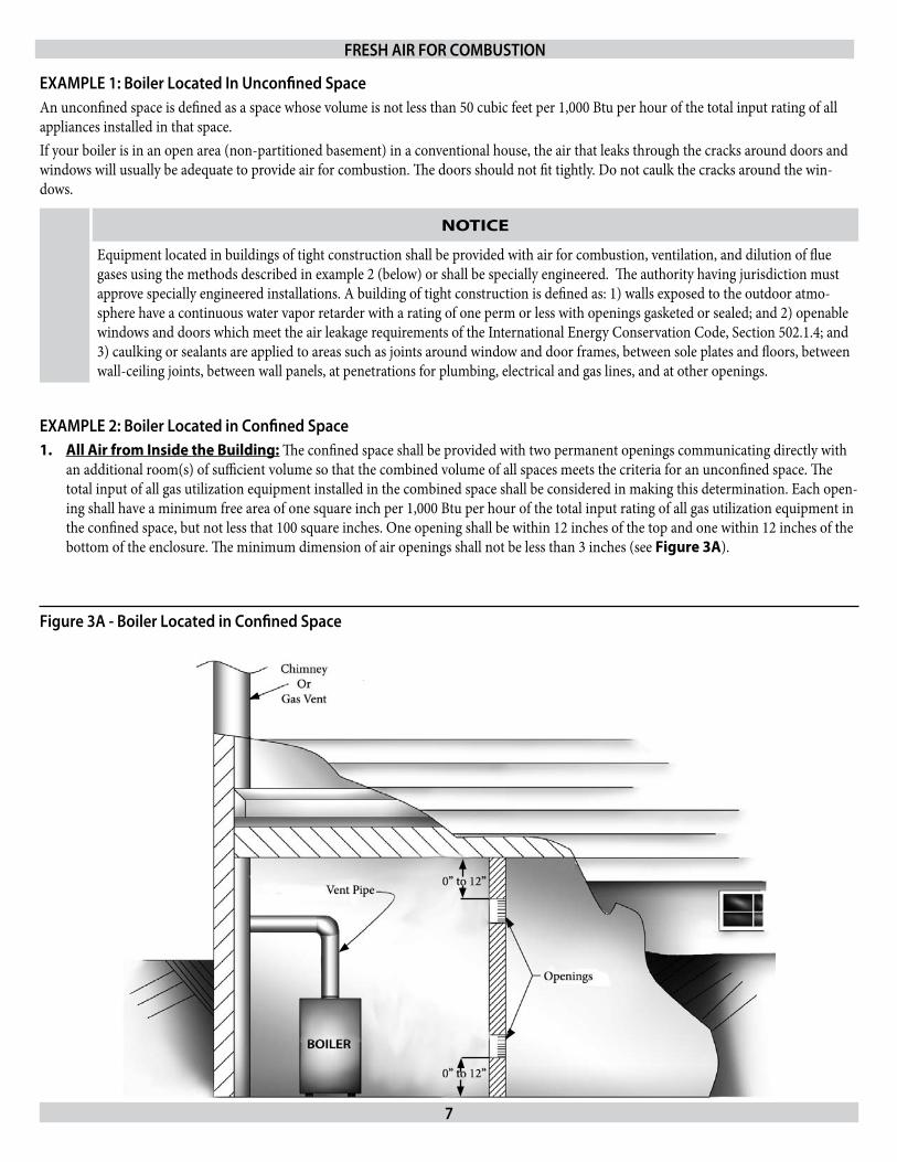
EXAmpLE 2: Boiler Located in Confined SpaceAll Air from Inside the Building:1. The confined space shall be provided with two permanent openings communicating directly with an additional room(s) of sufficient volume so that the combined volume of all spaces meets the criteria for an unconfined space. The total input of all gas utilization equipment installed in the combined space shall be considered in making this determination. Each open-ing shall have a minimum free area of one square inch per 1,000 Btu per hour of the total input rating of all gas utilization equipment in the confined space, but not less that 100 square inches. One opening shall be within 12 inches of the top and one within 12 inches of the bottom of the enclosure. The minimum dimension of air openings shall not be less than 3 inches (see Figure 3A).
FrESH AIr FOr COmBuSTION
NOTICE
Equipment located in buildings of tight construction shall be provided with air for combustion, ventilation, and dilution of flue gases using the methods described in example 2 (below) or shall be specially engineered. The authority having jurisdiction must approve specially engineered installations. A building of tight construction is defined as: 1) walls exposed to the outdoor atmo-sphere have a continuous water vapor retarder with a rating of one perm or less with openings gasketed or sealed; and 2) openable windows and doors which meet the air leakage requirements of the International Energy Conservation Code, Section 502.1.4; and 3) caulking or sealants are applied to areas such as joints around window and door frames, between sole plates and floors, between wall-ceiling joints, between wall panels, at penetrations for plumbing, electrical and gas lines, and at other openings.
Figure 3A - Boiler Located in Confined Space
8
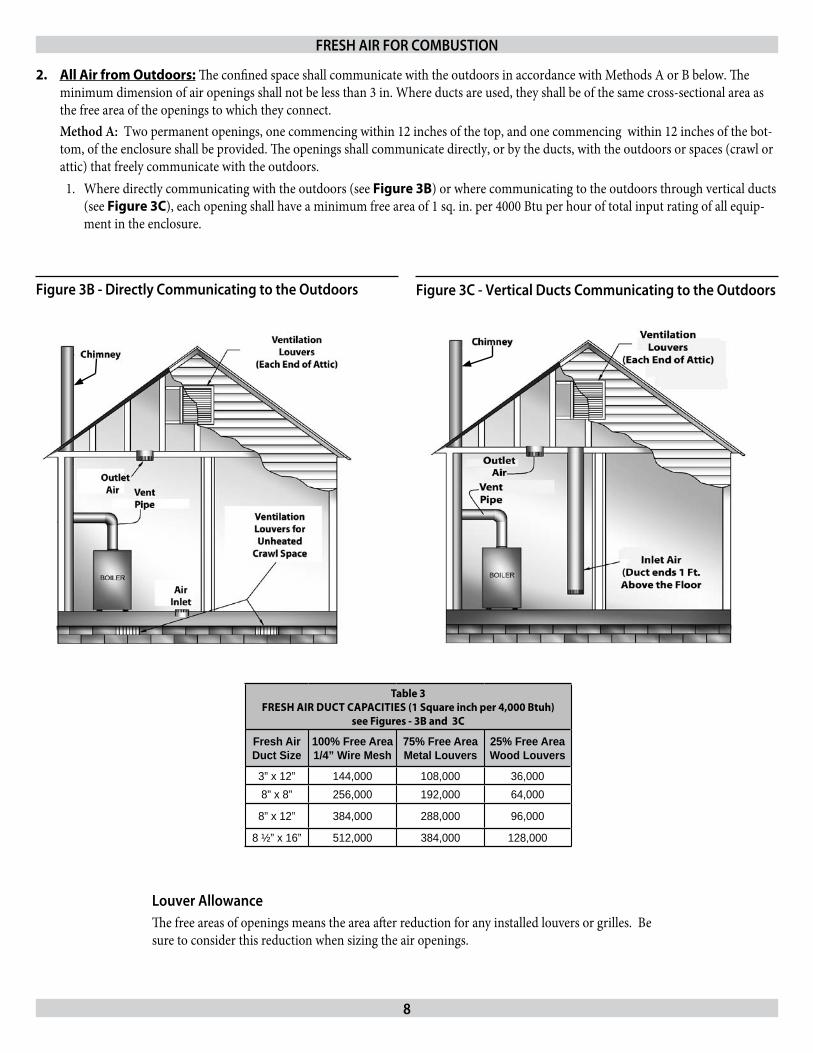
All Air from Outdoors:2. The confined space shall communicate with the outdoors in accordance with Methods A or B below. The minimum dimension of air openings shall not be less than 3 in. Where ducts are used, they shall be of the same cross-sectional area as the free area of the openings to which they connect. Method A: Two permanent openings, one commencing within 12 inches of the top, and one commencing within 12 inches of the bot-tom, of the enclosure shall be provided. The openings shall communicate directly, or by the ducts, with the outdoors or spaces (crawl or attic) that freely communicate with the outdoors.
Where directly communicating with the outdoors (see 1. Figure 3B) or where communicating to the outdoors through vertical ducts (see Figure 3C), each opening shall have a minimum free area of 1 sq. in. per 4000 Btu per hour of total input rating of all equip-ment in the enclosure.
Table 3 FRESh AIR DUCT CAPACITIES (1 Square inch per 4,000 Btuh)
see Figures - 3B and 3C
Fresh Air Duct Size
100% Free Area1/4” Wire Mesh
75% Free AreaMetal Louvers
25% Free AreaWood Louvers
3” x 12” 144,000 108,000 36,0008” x 8” 256,000 192,000 64,000
8” x 12” 384,000 288,000 96,000
8 ½” x 16” 512,000 384,000 128,000
Figure 3B - directly Communicating to the Outdoors Figure 3C - Vertical ducts Communicating to the Outdoors
FrESH AIr FOr COmBuSTION
Louver AllowanceThe free areas of openings means the area after reduction for any installed louvers or grilles. Be sure to consider this reduction when sizing the air openings.
9
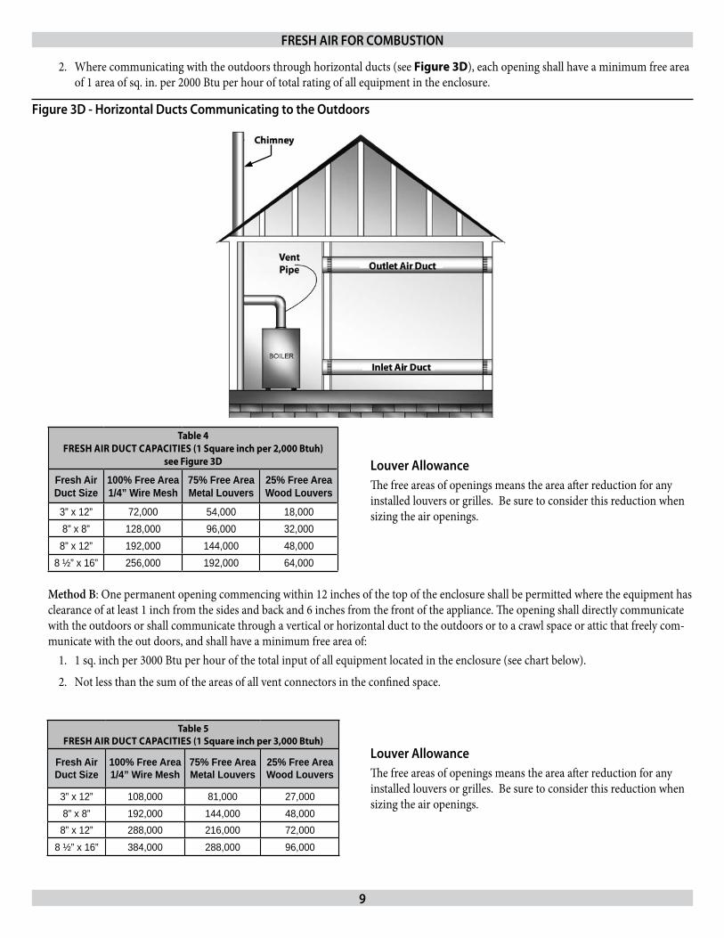
Table 4FRESh AIR DUCT CAPACITIES (1 Square inch per 2,000 Btuh)
see Figure 3D
Fresh Air Duct Size
100% Free Area1/4” Wire Mesh
75% Free AreaMetal Louvers
25% Free AreaWood Louvers
3” x 12” 72,000 54,000 18,0008” x 8” 128,000 96,000 32,0008” x 12” 192,000 144,000 48,000
8 ½” x 16” 256,000 192,000 64,000
Where communicating with the outdoors through horizontal ducts (see 2. Figure 3D), each opening shall have a minimum free area of 1 area of sq. in. per 2000 Btu per hour of total rating of all equipment in the enclosure.
FrESH AIr FOr COmBuSTION
Figure 3d - Horizontal ducts Communicating to the Outdoors
Table 5 FRESh AIR DUCT CAPACITIES (1 Square inch per 3,000 Btuh)
Fresh Air Duct Size
100% Free Area1/4” Wire Mesh
75% Free AreaMetal Louvers
25% Free AreaWood Louvers
3” x 12” 108,000 81,000 27,0008” x 8” 192,000 144,000 48,0008” x 12” 288,000 216,000 72,000
8 ½” x 16” 384,000 288,000 96,000
Method B: One permanent opening commencing within 12 inches of the top of the enclosure shall be permitted where the equipment has clearance of at least 1 inch from the sides and back and 6 inches from the front of the appliance. The opening shall directly communicate with the outdoors or shall communicate through a vertical or horizontal duct to the outdoors or to a crawl space or attic that freely com-municate with the out doors, and shall have a minimum free area of:
1 sq. inch per 3000 Btu per hour of the total input of all equipment located in the enclosure (see chart below).1.
Not less than the sum of the areas of all vent connectors in the confined space.2.
Louver AllowanceThe free areas of openings means the area after reduction for any installed louvers or grilles. Be sure to consider this reduction when sizing the air openings.
Louver AllowanceThe free areas of openings means the area after reduction for any installed louvers or grilles. Be sure to consider this reduction when sizing the air openings.
10
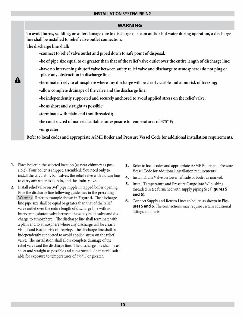
Place boiler in the selected location (as near chimney as pos-1. sible). Your boiler is shipped assembled. You need only to install the circulator, ball valves, the relief valve with a drain line to carry any water to a drain, and the drain valve.Install relief valve on 3/4” pipe nipple in tapped boiler opening. 2. Pipe the discharge line following guidelines in the preceding Warning. Refer to example shown in Figure 4. The discharge line pipe size shall be equal or greater than that of the relief valve outlet over the entire length of discharge line with no intervening shutoff valve between the safety relief valve and dis-charge to atmosphere. The discharge line shall terminate with a plain end to atmosphere where any discharge will be clearly visible and is at no risk of freezing. The discharge line shall be independently supported to avoid applied stress on the relief valve. The installation shall allow complete drainage of the relief valve and the discharge line. The discharge line shall be as short and straight as possible and constructed of a material suit-able for exposure to temperatures of 375° F or greater.
INSTALLATION SySTEm pIpINg
Refer to local codes and appropriate ASME Boiler and Pressure 3. Vessel Code for additional installation requirements.Install Drain Valve on lower left side of boiler as marked. 4. Install Temperature and Pressure Gauge into ¼” bushing 5. threaded in tee furnished with supply piping See Figures 5 and 6).Connect Supply and Return Lines to boiler, as shown in 6. Fig-ures 5 and 6. The connections may require certain additional fittings and parts.
!
WARNING
To avoid burns, scalding, or water damage due to discharge of steam and/or hot water during operation, a discharge line shall be installed to relief valve outlet connection.The discharge line shall:
connect to relief valve outlet and piped down to safe point of disposal.•be of pipe size equal to or greater than that of the relief valve outlet over the entire length of discharge line;•have no intervening shutoff valve between safety relief valve and discharge to atmosphere (do not plug or •place any obstruction in discharge line.terminate freely to atmosphere where any discharge will be clearly visible and at no risk of freezing;•allow complete drainage of the valve and the discharge line;•be independently supported and securely anchored to avoid applied stress on the relief valve;•be as short and straight as possible;•terminate with plain end (not threaded);•be constructed of material suitable for exposure to temperatures of 375° F;•or greater.•
Refer to local codes and appropriate ASME Boiler and Pressure Vessel Code for additional installation requirements.
11
Figure 5 - Forced hot Water Typical Piping
Figure 6 - Forced Hot Water Typical piping With Zone Control Valve
INSTALLATION SySTEm pIpINg
Check local codes for maximum distance from
floor or other al-lowable safe point
of discharge
rELIEF VALVE
Figure 4 - relief Valve discharge piping
dISCHArgE pIpINg

12
If you are installing an entire new heating system, first install all of your radiation units (panels, radiators or cabinets) and the Supply and Return Mains - then make the connections at the boiler. In connecting the cold water supply to the water valve, make sure that a clean water supply is available. When the water supply is from a well or pump, a sand strainer should be installed at the pump.A hot water boiler installed above radiation level must be equipped with a low water cutoff device. A periodic inspection is necessary, as is flushing of float type devices, per manufacturers specific instruc-tions.When the boiler is used in connection with refrigeration systems it shall be installed so that the chilled medium is piped in parallel with the heating boiler with appropriate valves to prevent the chilled medium from entering the heating boiler (Figure 7).If the boiler is connected to heating coils located in air handling units where they may be exposed to refrigerated air circulation, the piping system shall be equipped with flow control valves or other automatic means to prevent gravity circulation of the boiler water during the cooling cycle.
INSTALLATION SySTEm pIpINg
Figure 7 - Piping Arrangements For Boiler When Used In Connection With Refrigeration System
Low design Water Temperature Systems (Below 140° F) And Large Water Content Systems:
! WARNING
Significant condensation may form in this boiler and/or the venting system if the boiler is operated with return temperatures of less than 120° F.
This condensation is corrosive and can eventually cause severe dam-age to the boiler and venting system. The minimum design return water temperature to prevent this condensation in the boiler and venting is 120°F. The minimum high limit setting is 140°F.If the boiler is to be used in a heating system where design water temperatures below 140°F are desired (e.g. radiant floor heating), a 3-way or 4-way mixing valve or suitable alternative is required to prevent low temperature return water from entering the boiler. When using a mixing valve, follow the manufacturer’s installation instructions.If the boiler is to be connected to a system having a large water con-tent (such as a former gravity system), it is suggested to use bypass piping shown in Figure 8.
Figure 8 - Bypass Piping
13
NOTICE
For boilers for connection to gas vents or chimneys, vent installations shall be in accordance with the National Fuel Gas Code, ANSI Z223.1- latest revision and applicable provisions of the local building codes.
Check your ChimneyThis is a very important part of your heating system. It must be clean, the right size, properly constructed and in GOOD CONDI-TION. No boiler can function properly with a bad chimney.
Use local codes for installation or National Fuel Gas Code 1. Z223.1-latest revision. In Canada, follow CSA B149.1 or .2 Installation Codes. It is very important to properly size the venting system for induced draft appliances. Consult the Vent Sizing Tables, in the National Fuel Gas Code ANSI Z223.1-latest revision for correct sizing information. In Canada, consult the Vent Sizing Tables, Amendment #1 to CSA-B149.1 and .2 Installation Codes.The boiler’s induced draft blower has a 3” outlet. A 3” X 4” 2. increaser fitting is included in the parts bag. Locate the in-creaser fitting on the outlet of the induced draft blower, and secure gastight with a bead of the furnished silicone sealant. The increaser fitting is required on this boiler for Category I venting, and 4” is the minimum permissible vent diameter. This does not imply that the vent connector is intended to be 4” diam-eter pipe. The vent connector shall be sized according to the appropriate venting tables in the National Fuel Gas Code or the Canadian Installation Codes, and may be required to be larger than 4” diameter.
NOTICE
The boiler installation for chimney venting is not complete unless the 3” x 4” increaser fitting is located and secured.
These are high efficiency boilers with a low stack or exhaust 3. temperature.If venting into a masonry chimney without a liner, line the 4. chimney from top to bottom with either:
Listed Type B vent pipe A. Listed flexible vent linerB. Poured ceramic liner. C.
Outside chimneys should not be used unless they are (choose 5. one of the following):
Enclosed in a chaseA. Lined with Type B vent pipeB. Use a listed flexible vent linerC. Use a certified chimney lining systemD.
The vent connector from the boiler to the chimney should run 6. as directly as possible with as few elbows as possible.
Where possible, it is recommended to common vent the water 7. heater and boiler. Consult the appropriate Vent Sizing Tables in either the National Fuel Gas Code, or the Canadian Installation Codes for specific requirements of multiple appliance venting.If the boiler is the only appliance connected to the vent, Type B 8. vent pipe is recommended for the vent connector.Slope pipe up from boiler to chimney not less than 1/4” per 9. foot.End of vent pipe must be flush with the inside face of the chim-10. ney flue. Use a sealed-in thimble for the chimney connection.The sections of vent pipe should be fastened with sheet metal 11. screws to make the piping rigid. Use stovepipe wires to support the pipe from above.Do not connect to fireplace flue.12. Do not install a damper on this boiler.13.
minimum Vent pipe ClearanceIf the vent pipe must go through a crawl space, Type B vent pipe should be used. Where vent pipe passes through a combustible wall or partition, use a ventilated metal thimble. The thimble should be 4 inches larger in diameter than the vent pipe. If boiler is installed with single wall vent, it must have a 6” clear-ance between its surface and any combustible material. A new Type B gas vent or flexible liner must be installed in accordance with the instructions furnished with the vent. Maintain clearances as speci-fied for the vent pipe.Check the vent pipe to see if it is fire-stopped where it goes through the floor or ceiling. It should have an approved vent cap with clear-ances from the roof as shown in Figure 9. If clearances are less than shown in Figure 9, have the vent checked by local authorities. For boilers for connection to gas vents or chimneys, vent installa-tions shall be in accordance with the National Fuel Gas Code, ANSI Z223.1-latest revision and applicable provisions of the local building codes. In Canada, follow CSA B149.1 or .2 Installation Codes.Vent connectors serving appliances vented by natural draft shall not be connected into any portion of mechanical draft systems operating under positive pressure.
removing Existing Boiler From Common Venting SystemWhen an existing boiler is removed from a common venting system, the common venting system is likely to be too large for proper vent-ing of the appliances remaining connected to it.At the time of removal of an existing boiler, the following steps shall be followed with each appliance remaining connected to the com-mon venting system placed in operation, while the other appliance remaining connected to the common venting system are not in operation.
Seal any unused openings in the common venting system.1. Visually inspect the venting system for proper size and hori-2.
CHImNEy & VENT pIpE CONNECTION
Liner
Chimney
Thimble
Vent System
Cleanout
Boiler
Boiler
Water Heater
Chimney
CHECK yOur CHImNEyThis is a very important part of your heating system. It must be clean, the right size, properly constructed and in GOOD CONDITION. No boiler can function properly with a bad chimney. Use local codes for instal-lation or National Fuel Gas Code Z223.1-latest revision. In Canada, follow CSA B149.1 or .2 Installation Codes. It is very important to properly size the venting system for induced draft appliances. Consult the Vent Sizing Tables, in the National Fuel Gas Code ANSI Z223.1-latest revision for correct sizing information. In Canada, consult the Vent Sizing Tables, Amendment #1 to CSA-B149.1 and .2 Installation Codes.
Figure 9 - Type B gas Vent
14
CHImNEy & VENT pIpE CONNECTION
15
zontal pitch and determine there is no blockage or restriction, leakage, corrosion and other deficiencies which could cause an unsafe condition.Insofar as is practical, close all building doors and windows and 3. all doors between the space in which the appliances remaining connected to the common venting system are located and other spaces of the building. Turn on clothes dryers and any appli-ance not connected to the common venting system. Turn on any exhaust fans, such as range hoods and bathroom exhausts, so they will operate at maximum speed. Close fireplace damp-ers.Place in operation the appliance being inspected. Follow the 4. lighting instructions. Adjust thermostat so appliance will operate continuously.Test for spillage at the hood relief opening after 5 minutes of 5. main burner operation. After it has been determined that each appliance remaining con-6.
CHImNEy & VENT pIpE CONNECTION
nected to the common venting system properly vents when tested as outlined above, return doors, windows, exhaust fans, fireplace dampers and any other gas-burning appliance to their previous conditions of use.Any improper operation of the common venting system should 7. be corrected so the installation conforms with the National Fuel Gas Code, ANSI Z223.1-latest revision. When resizing any portion of the common venting system, the common venting system should be resized to approach the minimum size as determined using the appropriate tables in the National Fuel Gas Code, ANSI Z223.1-latest revision. In Canada, follow CSA B149.1 or.2 Installation Codes.
NOTICE
NOTE: It is recommended that existing gas vents be checked to be sure they meet local codes.

16
Maximum Horizontal Vent Length For Stainless Steel Vent Pipe - 30’ Plus One 90º Elbow Plus Vent Terminal.Minimum Horizontal Vent Length - 2’ Plus One 90º Elbow Vent Termination.Additional elbows are equivalent to 6 feet of straight pipe for 4” di-ameter 90° elbow or 3 feet of straight pipe for 3” diameter 90° elbow. 2, 3, 4, 5, Section Boilers use 3” vent pipe; for 6, 7 Section Boilers use 4” vent pipe.
ChOICE OF VENT PIPE MATERIALU. L. Listed Z-Flex Z-Vent Stainless Steel Vent Pipe.1. U. L. Listed Heat-Fab Saf-T-Vent Stainless Steel Vent Pipe.2. U. L. Listed Flex-L Star-34 Stainless Steel Vent Pipe.3. U. L. Listed ProTech Systems FasNSeal Stainless Steel Vent Pipe.4.
INDUCED DRAFT HIGH EFFICIENCY BOILERS
HOrIZONTAL VENTINg INSTruCTIONS
Figure 10 - Induced draft High Efficiency boilers
17
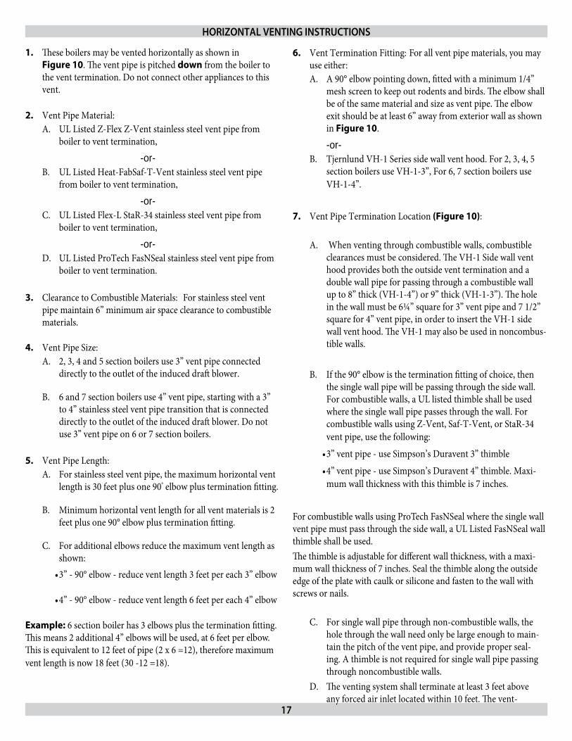
These boilers may be vented horizontally as shown in 1. Figure 10. The vent pipe is pitched down from the boiler to the vent termination. Do not connect other appliances to this vent.
Vent Pipe Material:2. UL Listed Z-Flex Z-Vent stainless steel vent pipe from A. boiler to vent termination,
-or-UL Listed Heat-FabSaf-T-Vent stainless steel vent pipe B. from boiler to vent termination,
-or-UL Listed Flex-L StaR-34 stainless steel vent pipe from C. boiler to vent termination,
-or-UL Listed ProTech FasNSeal stainless steel vent pipe from D. boiler to vent termination.
Clearance to Combustible Materials:3. For stainless steel vent pipe maintain 6” minimum air space clearance to combustible materials.
Vent Pipe Size:4. 2, 3, 4 and 5 section boilers use 3” vent pipe connected A. directly to the outlet of the induced draft blower.
6 and 7 section boilers use 4” vent pipe, starting with a 3” B. to 4” stainless steel vent pipe transition that is connected directly to the outlet of the induced draft blower. Do not use 3” vent pipe on 6 or 7 section boilers.
Vent Pipe Length:5. For stainless steel vent pipe, the maximum horizontal vent A. length is 30 feet plus one 90° elbow plus termination fitting.
Minimum horizontal vent length for all vent materials is 2 B. feet plus one 90° elbow plus termination fitting.
For additional elbows reduce the maximum vent length as C. shown: 3” - 90° elbow - reduce vent length 3 feet per each 3” elbow•
4” - 90° elbow - reduce vent length 6 feet per each 4” elbow •
Example: 6 section boiler has 3 elbows plus the termination fitting. This means 2 additional 4” elbows will be used, at 6 feet per elbow. This is equivalent to 12 feet of pipe (2 x 6 =12), therefore maximum vent length is now 18 feet (30 -12 =18).
Vent Termination Fitting:6. For all vent pipe materials, you may use either:
A 90° elbow pointing down, fitted with a minimum 1/4” A. mesh screen to keep out rodents and birds. The elbow shall be of the same material and size as vent pipe. The elbow exit should be at least 6” away from exterior wall as shown in Figure 10.
-or-Tjernlund VH-1 Series side wall vent hood. For 2, 3, 4, 5 B. section boilers use VH-1-3”, For 6, 7 section boilers use VH-1-4”.
Vent Pipe Termination Location7. (Figure 10):
When venting through combustible walls, combustible A. clearances must be considered. The VH-1 Side wall vent hood provides both the outside vent termination and a double wall pipe for passing through a combustible wall up to 8” thick (VH-1-4”) or 9” thick (VH-1-3”). The hole in the wall must be 6¼” square for 3” vent pipe and 7 1/2” square for 4” vent pipe, in order to insert the VH-1 side wall vent hood. The VH-1 may also be used in noncombus-tible walls.
If the 90° elbow is the termination fitting of choice, then B. the single wall pipe will be passing through the side wall. For combustible walls, a UL listed thimble shall be used where the single wall pipe passes through the wall. For combustible walls using Z-Vent, Saf-T-Vent, or StaR-34 vent pipe, use the following:
3” vent pipe - use Simpson’s Duravent 3” thimble •
4” vent pipe - use Simpson’s Duravent 4” thimble. Maxi-•mum wall thickness with this thimble is 7 inches.
For combustible walls using ProTech FasNSeal where the single wall vent pipe must pass through the side wall, a UL Listed FasNSeal wall thimble shall be used. The thimble is adjustable for different wall thickness, with a maxi-mum wall thickness of 7 inches. Seal the thimble along the outside edge of the plate with caulk or silicone and fasten to the wall with screws or nails.
For single wall pipe through non-combustible walls, the C. hole through the wall need only be large enough to main-tain the pitch of the vent pipe, and provide proper seal-ing. A thimble is not required for single wall pipe passing through noncombustible walls.The venting system shall terminate at least 3 feet above D. any forced air inlet located within 10 feet. The vent-
HOrIZONTAL VENTINg INSTruCTIONS
18
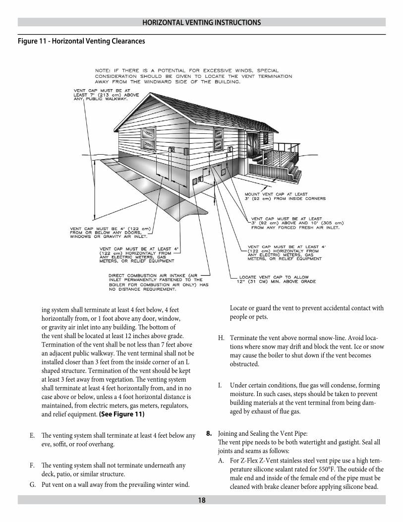
ing system shall terminate at least 4 feet below, 4 feet horizontally from, or 1 foot above any door, window, or gravity air inlet into any building. The bottom of the vent shall be located at least 12 inches above grade. Termination of the vent shall be not less than 7 feet above an adjacent public walkway. The vent terminal shall not be installed closer than 3 feet from the inside corner of an L shaped structure. Termination of the vent should be kept at least 3 feet away from vegetation. The venting system shall terminate at least 4 feet horizontally from, and in no case above or below, unless a 4 foot horizontal distance is maintained, from electric meters, gas meters, regulators, and relief equipment. (See Figure 11)
The venting system shall terminate at least 4 feet below any E. eve, soffit, or roof overhang.
The venting system shall not terminate underneath any F. deck, patio, or similar structure.Put vent on a wall away from the prevailing winter wind. G.
Locate or guard the vent to prevent accidental contact with people or pets.
Terminate the vent above normal snow-line. Avoid loca-H. tions where snow may drift and block the vent. Ice or snow may cause the boiler to shut down if the vent becomes obstructed.
Under certain conditions, flue gas will condense, forming I. moisture. In such cases, steps should be taken to prevent building materials at the vent terminal from being dam-aged by exhaust of flue gas.
Joining and Sealing the Vent Pipe: 8. The vent pipe needs to be both watertight and gastight. Seal all joints and seams as follows:
For Z-Flex Z-Vent stainless steel vent pipe use a high tem-A. perature silicone sealant rated for 550°F. The outside of the male end and inside of the female end of the pipe must be cleaned with brake cleaner before applying silicone bead.
HOrIZONTAL VENTINg INSTruCTIONS
Figure 11 - Horizontal Venting Clearances

19
For 3” vent pipe runs begin with the male end of the vent pipe over the boilers induced draft blower outlet. For 4” vent pipe runs begin with a 6” length of 3” Z-Vent over the boiler’s induced draft blower outlet, to which an even bead of high temperature silicone sealant should be applied. Then connect the 3” Z-Vent to a Z-Vent 3” to 4” reducer. Then continue the 4” Z-Vent pipe run by connecting the 4” male end of the Z-Vent to the reducer. (A locking band may be used around this joint for additional support.) Then following the sealing instructions, push the 4” male end of the Z-Vent over the 4” increaser fitting. When using the Tjernlund VH-1 vent hood, the female end (flared end) of the vent pipe will be connected to the termination hood. The male end of the vent hood must be crimped before pushing the Z-Vent over the vent hood’s connecting pipe. Before the pipes are joined, apply a ¼” bead of silicone one inch from the end of the male end. Then push the pipes together as far as they will go making sure any seams are aligned and oriented upward. Now apply another bead of silicone around this joint and smooth out. Then use a Z-Flex locking band around the center of the joint.
Apply the high temperature silicone approximately one 1. inch from the end, around the male end of the pipe in an even ¼” bead.
Pipes can now be pushed together as far as they will 2. go. The seams on pipe should be aligned and oriented upward in all horizontal appliances. Apply another bead of silicone around this joint and smooth out.
Slide locking band over center of joint and tighten gear 3. clamps. Make sure locking band is centered on joint.
Check all joints and seams for gas tightness.4.
Horizontal venting shall have a slope not less than ¼” 5. (6.4mm) every 12 inches (305mm) downward away from the boiler to prevent collection of condensate throughout the assembly.
Allow the sealant to cure for 24 hours before operating 6. the appliance.
For Heat-Fab Saf-T-Vent stainless steel vent pipe use B. a high temperature silicone sealant rated for 550°F The outside of the male end and inside of the female end of the pipe must be cleaned before applying the silicone bead. For 3” vent pipe runs, the male end of the vent pipe which goes over the outlet of the boiler’s induced draft blower must be crimped. The vent pipe should be crimped as minimal as possible to provide a tight fit over the outlet. After crimping is completed follow the instructions for applying silicone sealant. For 4” vent pipe runs, begin with a Saf-T-Vent 3” to 4” in-creaser fitting over the boiler’s induced draft blower outlet,
to which an even bead of high temperature silicone sealant should be applied. Then continue the 4” Saf-T-Vent pipe run by connecting the 4” male end of the Saf-T-Vent to the increaser. (A locking band may be used around this joint for additional support.) The vent flow must be in the direc-tion indicated on the vent pipe. When using the Tjernlund VH-1 vent hood, the female end (flared end) of the vent pipe will be connected to the termination hood. Apply high temperature silicone in an even ¼” bead approximately ¼” to ⅜” from the end of the vent hood’s connecting vent pipe. Also, run a similar size bead of silicone sealant down the seam weld of the vent pipe. Then push the female end over the vent hood’s connecting vent pipe.
Apply the high temperature silicone around the male 1. end of the pipe (without the tabs) in an even ¼” bead. Silicone bead should be approximately ¼” to ⅜” from the end of the male end. Also, run a similar size bead of silicone sealant down the seam weld at the end of each joint.
Pipes can now be pushed together as far as they will 2. go. The seams on the vent pipe should be aligned and oriented upward in all horizontal appliances. With a moistened finger or flat tool, spread any sealant that squeezes out around the circumference of the joint.
Attach the sections together with the locking rings and 3. tabs (except at the blower outlet where no locking ring exists.) Inspect the joint to ensure that flue gases will not leak. If necessary apply additional sealant around the joint.
Horizontal venting shall have a slope not less than ¼” 4. (6.4mm) every 12 inches (305mm) downward away from the boiler to prevent collection of condensate throughout the assembly.
Allow the sealant to cure for 24 hours before operating 5. the appliance.
For Flex-L StaR-34 stainless steel vent pipe use a high C. temperature silicone sealant rated for 550°F. Before apply-ing silicone, the outside of the male end and inside of the female end of the pipe must be cleaned using a cleaner, such as methyl ethyl ketone (MEK) or naptha. For 3” vent pipe runs, begin with the male end of the vent pipe over the boiler’s induced draft blower outlet. For 4” vent pipe runs begin with a StaR-34 3” to 4” increaser fitting over the boiler’s induced draft blower outlet. For both 3” and 4” vent pipe runs, apply a bead of silicone seal-ant around the blower outlet and around the inside of the male end of vent pipe going over the blower’s outlet. When using the Tjernlund VH-1 vent hood,the female end (flared end) of the vent pipe will be connected to the termination hood.
HOrIZONTAL VENTINg INSTruCTIONS
20
Apply high temperature silicone in an even ¼” bead ap-proximately ¼” from the end of the vent hood’s connecting vent pipe. Also, run a similar size bead of silicone sealant down the seam weld of the vent pipe. Then push the female end over the vent hood’s connecting vent pipe. Now fill in the channel inlet with silicone sealant. Do not try to insert the joiner band, instead fasten the vent pipe to the vent hood’s pipe with a steel gear clamp.
Apply the high temperature silicone around the male 1. end of the pipe in an even ¼” bead. Silicone bead should be approximately ¼” from the end of the male end. Also, run a similar size bead of silicone sealant down the seam weld at the end of each joint.
The seams on the vent pipe should be aligned and ori-2. ented upward in all horizontal vent pipe runs.
Insert the male end of one into the female end of the 3. other. Push the pipe together so the female end rests up against the stop bead of the male end.
Insert a StaR-Joiner Band into the inlet of the beaded 4. channel. Feed the Joiner Band in so it makes its way around the pipe, back to the channel inlet and it over-laps itself by about ½”.
Cut the excess Joiner Band so it lays flat in the beaded 5. channel. Fill the inlet of the beaded channel with high temperature silicone. Smooth out the silicone over the channel inlet and the silicone between the female end and the stop bead of the male end.
Horizontal venting shall have a slope not less than ¼” 6. (6.4mm) every 12 inches (305mm) downward away from the boiler to prevent collection of condensate throughout the assembly.
Allow the sealant to cure for 24 hours before operating 7. the appliance.
For ProTech Systems FasNSeal stainless steel vent pipe D. no cleaning fluid is required. For 3” vent pipe runs on 2, 3, 4 and 5 section boilers, begin by locating the FasNSeal Ametek Adapter over the boiler’s induced draft blower. Continue the vent pipe run with 3” FasNSeal vent pipe. For 6 and 7 section boilers, begin by locating the FasNSeal Ametek Adapter over the boiler’s induced draft blower. Then connect a FasNSeal 3” to 4” increaser to the 3” adapter outlet. Continue the vent pipe run with 4” FasNSeal vent pipe. Other than the Ametek Adapter and increaser fitting, DO NOT use 3” vent pipe on 6 or 7 section boilers. FasNSeal vent pipe is joined and sealed by the use of an internal sealing gasket and a locking band on the female end of each vent pipe. All components should be examined for possible shipping damage prior to installation. Align
all vent pipe seams and orient upward in all horizontal applications. Adjustable vent lengths are available for 4” diameter vent piping. For 3” diameter vent piping, square cut male end at the desired length. For 2, 3, 4 and 5 section boilers using the VH-1-3” vent hood, connect the FasNSeal Vent to the VH-1-3” vent hood using FasNSeal Adapter #FSC-DUN-3. This adapter has no internal sealing gasket. To attach the adapter to the vent hood, crimp the 3” vent hood pipe, apply a ¼” bead of high temperature silicone sealant around the outside of the vent hood’s crimped connecting pipe and a similar bead of high temperature silicone around the inside of the FasNSeal adapter. After pressing the two pipes together and tightening the locking band, finish creating a complete seal by filling the FasNSeal adapter’s notched hole with high temperature silicone. For 6 and 7 section boilers using the VH-1 - 4” vent hood, an adapter is not required. The 4” FasNSeal vent pipe con-nects directly to the VH-1- 4” vent hood, and is joined and sealed by the internal gasket and locking band.
To join and seal the FasNSeal vent pipe:Insert male end into female section.1.
Push the units together as far as possible.2.
Firmly tighten locking band with a nut driver.3.
DO NOT penetrate the FasNSeal vent pipe with fasten-4. ers.
Horizontal venting shall have a slope of not less than 5. ¼” (6.4mm) every 12 inches (305mm) downward away from the boiler to prevent the collection of condensate throughout the assembly.
Support Spacing:9. Do not restrict thermal expansion movement of the vent. The vent pipe must expand and contract freely with temperature change. Each run of vent piping shall be supported as follows:
Z-Flex stainless steel vent piping requires a loose fitting A. metal strap or similar support at each joint at a maximum of 4 feet between supports.Heat-Fab stainless steel vent piping requires a support for B. every 6 feet of horizontal piping run. The support must be secured using at least #10 fasteners to a solid material (solid masonry or wood framing or blocking.) Do not fasten to drywall sheathing using hollow wall anchors. Each sup-port will be 1½ inch lower than the previous support when spaced 6 feet apart.Flex-L stainless steel vent piping requires a loose fitting C. metal strap or similar support at each joint at a maximum of 4 feet between supports. ProTech stainless steel vent piping requires one loose fit-D. ting FasNSeal support strap for every 6’ of horizontal vent.
HOrIZONTAL VENTINg INSTruCTIONS
21
If the horizontal vent must go through a crawl space or other 10. unheated space, the cool temperatures will likely cause the flue gases to continuously condense inside the vent pipe. Do not insulate the vent pipe. It must be visible for monthly inspec-tion. Insure that the vent pipe is properly pitched away from the boiler, with no low spots, so that condensate in the vent will drain away from the boiler. An insulated enclosure or chase, with access for inspection and servicing of the vent, may be
required to prevent freezing of liquid condensate. Consult the vent pipe manufacturer’s instructions for specific guidelines.At the beginning of each heating season and monthly during 11. the heating season, check all vent pipes and the vent terminal to make sure there are no obstructions. Periodically clean the screen in the vent terminal.
OpTIONAL HOrIZONTAL VENTINg INSTruCTION
HOrIZONTAL VENTINg INSTruCTIONS
Horizontal venting with a power venter is an alternate method of sidewall venting. This boiler is CSA listed for sidewall venting with standard single wall galvanized or Type B vent pipe when using the following power venter kits, which were specifically sized for these boilers:
Table 6Number Of
Boiler SectionsField ControlsPower Venter
2, 3, 4, 5 SWG-4D6, 7 SWG-5D
Some possible reasons for using a power venter for sidewall venting: May be preferred by local codes.1. Need a vent piping run beyond 30’ (but not more than 50’).2. The boiler installation site experiences gusting or high winds. A 3. power venter can help prevent the boiler from short cycling due to gusting or high winds by providing vent exhaust pressures greater than the boiler’s induced draft blower alone.When installers or homeowners prefer a negative pressure vent 4. system instead of a positive pressure vent system.May be more cost effective than stainless steel 5. venting, particularly at longer vent lengths. The Field Controls power vent kit includes either a SWG-II-4HD or SWG-II-5 power venter, a MG-1 4” barometric draft controller, and the CK-43D controls kit.
Confirm that installing a power venter is an option allowed by local
codes. Follow the specific power venter installation instructions issued with the power venter kits. Although the power venter is equipped with its own fan, the fan on the boiler remains in place and is unaltered when a power venter is used. When sidewall venting, flue gases must be vented to a point in rela-tion to the prevailing wind so that they may freely disperse without being blown back at the building causing discoloration, or into the building through doors or windows causing odors. Also, under cer-tain conditions flue gases will condense, forming moisture. In such cases, steps should be taken to prevent building materials at the vent terminal from being damaged by the exhausted flue gas.When installing single wall galvanized vent pipe for power venting follow the specific power venter installation instructions for layout, location of the barometric draft control and termination connec-tions. When joining and sealing the single wall galvanized or Type B vent piping, use RTV silicone sealant with a minimum temperature rating of 400°F. For 3” vent pipe runs, begin with the female end of the vent pipe over the boiler’s induced draft blower outlet. For 4” vent pipe runs begin with the galvanized 3” to 4” increaser fitting (included in the boiler’s parts bag) over the induced draft blower outlet. Then fol-low by placing the female end of the 4” vent pipe over the increaser fitting. When joining pieces of single wall galvanized vent pipe, a substan-tial bead of silicone should be used at the joint to insure a leakproof connection.
22
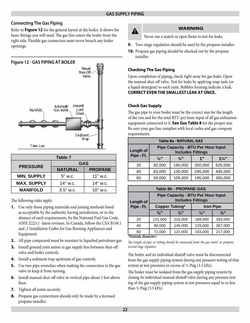
Connecting The gas pipingRefer to Figure 12 for the general layout at the boiler. It shows the basic fittings you will need. The gas line enters the boiler from the right side. Flexible gas connectors must never breach any boiler openings.
Table 7
PRESSURE GASNATURAL PROPANE
MIN. SUPPLY 5" w.c. 11" w.c.MAX. SUPPLY 14" w.c. 14" w.c.
MANIFOLD 3.5" w.c. 10" w.c.
The following rules apply: Use only those piping materials and joining methods listed 1. as acceptable by the authority having jurisdiction, or in the absence of such requirements, by the National Fuel Gas Code, ANSI Z223.1- latest revision. In Canada, follow the CSA B149.1 and .2 Installation Codes for Gas Burning Appliances and Equipment.All pipe compound must be resistant to liquefied petroleum gas.2. Install ground joint union in gas supply line between shut-off 3. valve and boiler controls.Install a sediment trap upstream of gas controls.4. Use two pipe wrenches when making the connection to the gas 5. valve to keep it from turning.Install manual shut-off valve in vertical pipe about 5 feet above 6. floor.Tighten all joints securely. 7. Propane gas connections should only be made by a licensed 8. propane installer.
Two-stage regulation should be used by the propane installer.9. Propane gas piping should be checked out by the propane 10. installer.
Checking The Gas PipingUpon completion of piping, check right away for gas leaks. Open the manual shut-off valve. Test for leaks by applying soap suds (or a liquid detergent) to each joint. Bubbles forming indicate a leak. CORRECT EVEN ThE SMALLEST LEAK AT ONCE.
Check Gas SupplyThe gas pipe to your boiler must be the correct size for the length of the run and for the total BTU per hour input of all gas utilization equipment connected to it. See Gas Table 8 for the proper size. Be sure your gas line complies with local codes and gas company requirements.
*Outside diameter:The length of pipe or tubing should be measured from the gas meter or propane second stage regulator.
Table 8a - NATURAL GAS
Length ofPipe - Ft.
Pipe Capacity - BTU Per Hour InputIncludes Fittings
½" ¾" 1" 1¼"20 92,000 190,000 350,000 625,00040 63,000 130,000 245,000 445,00060 50,000 105,000 195,000 365,000
Table 8b - PROPANE GAS
Length ofPipe - Ft.
Pipe Capacity - BTU Per Hour InputIncludes Fittings
Copper Tubing* Iron Pipe⅝" ¾" ½" ¾"
20 131,000 216,000 189,000 393,00040 90,000 145,000 129,000 267,00060 72,000 121,000 103,000 217,000
The boiler and its individual shutoff valve must be disconnected from the gas supply piping system during any pressure testing of that system at test pressures in excess of ½ Psig (3.5 kPa).The boiler must be isolated from the gas supply piping system by closing its individual manual shutoff valve during any pressure test-ing of the gas supply piping system at test pressures equal to or less than ½ Psig (3.5 kPa).
gAS SuppLy pIpINg
SedimentTrap
Manifold
Floor Line
Automatic Gas Valve
Ground Joint Union
Figure 12 - gAS pIpINg AT BOILEr
! WARNING
Never use a match or open flame to test for leaks.
23
All electrical work must conform to local codes as well as the Na-tional Electrical Code, ANSI/NFPA-70, latest revision. In Canada, electrical wiring shall comply with the Canadian Electrical Code, CSA-C22.1.
! WARNING
Turn off electric power at fuse box before making any line voltage connections. Follow local electrical codes.
Electric Power SupplyRun a separate 120 volt circuit from a separate over current protec-tive device in the electrical service entrance panel. This should be a 15 ampere circuit. Locate a shut-off switch at the boiler. It must be turned off during any maintenance. Connect 120 volt power supply to aquastat terminals L1 (HOT) and L2.The boiler, when installed, must be electrically grounded in accor-dance with the requirements of the authority having jurisdiction or, in the absence of such requirements, with the National Electrical Code, ANSI/NFPA No. 70 - latest revision. Run a 14 gauge or heavier copper wire from the boiler to a grounded connection in the service panel or a properly driven and electrically grounded ground rod.
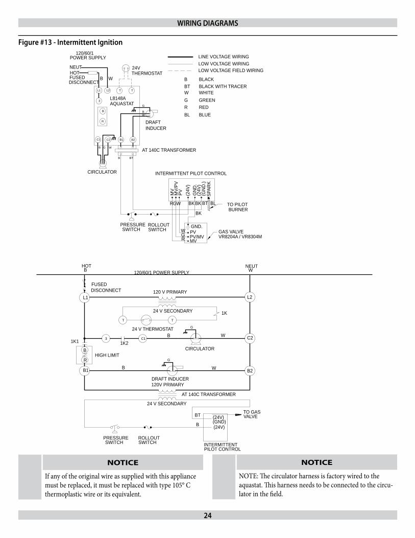
Sequence of Operation - refer to Figure 13Thermostat calls for heat, powering the 1K relay coil and closing 1. contacts 1K1 and 1K2.Circulator pump is powered through terminals C1 and C2. 2. Induced draft blower and transformer primary are powered 3. through terminals B1 and B2.When blower gets up to speed and blower suction pressure 4. reaches pressure switch set point, pressure switch contacts close sending 24 volts to intermittent pilot control from transformer secondary.Pilot gas valve opens and spark initiates to light pilot burner. 5. When pilot flame is proven, spark drops out.6. Main gas valve opens and pilot burner ignites main burners.7.
ThERMOSTAT LOCATIONS TO AVOIDDEAD SPOTS HOT SPOTS COLD SPOTS
Behind doors Concealed pipes Concealed pipes
or ductsFireplaceTV sets Stairwells - drafts
Corners & alcoves
Radios Doors - draftsLamps
Unheated room on other side of wallDirect sunlight
Kitchens
Set heat anticipator at .2 amps. The 24 volt thermostat connects to aquastat terminals T and T.
If boiler water temperature reaches high limit set point, high 8. limit contacts B-R open, cutting power to blower and intermit-tent pilot control. Burners extinguish and blower stops. Circula-tor pump continues to run as long as the thermostat continues to call for heat. When boiler water temperature drops past the high limit set point and through the differential, high limit contacts B-R close, repeating steps 3-7.If venting system becomes blocked, blower suction pressure will 9. drop below the pressure switch set point, opening the pressure switch contacts and cutting power to the intermittent pilot con-trol. Burners will extinguish, but blower will remain powered as long as the thermostat continues to call for heat. If venting system clears, steps 4-7 will repeat.Thermostat is satisfied, ending call for heat. Relay coil 1K is de-10. energized, opening 1K1 and 1K2 contacts. Burners extinguish. Blower and circulator pump stop.
ELECTrICAL WIrINg
SEquENCE OF OpErATION
! CAUTION
Label all wires prior to disconnection when servicing controls. Wiring errors can cause improper and dangerous operation. Verify proper operation after servicing.
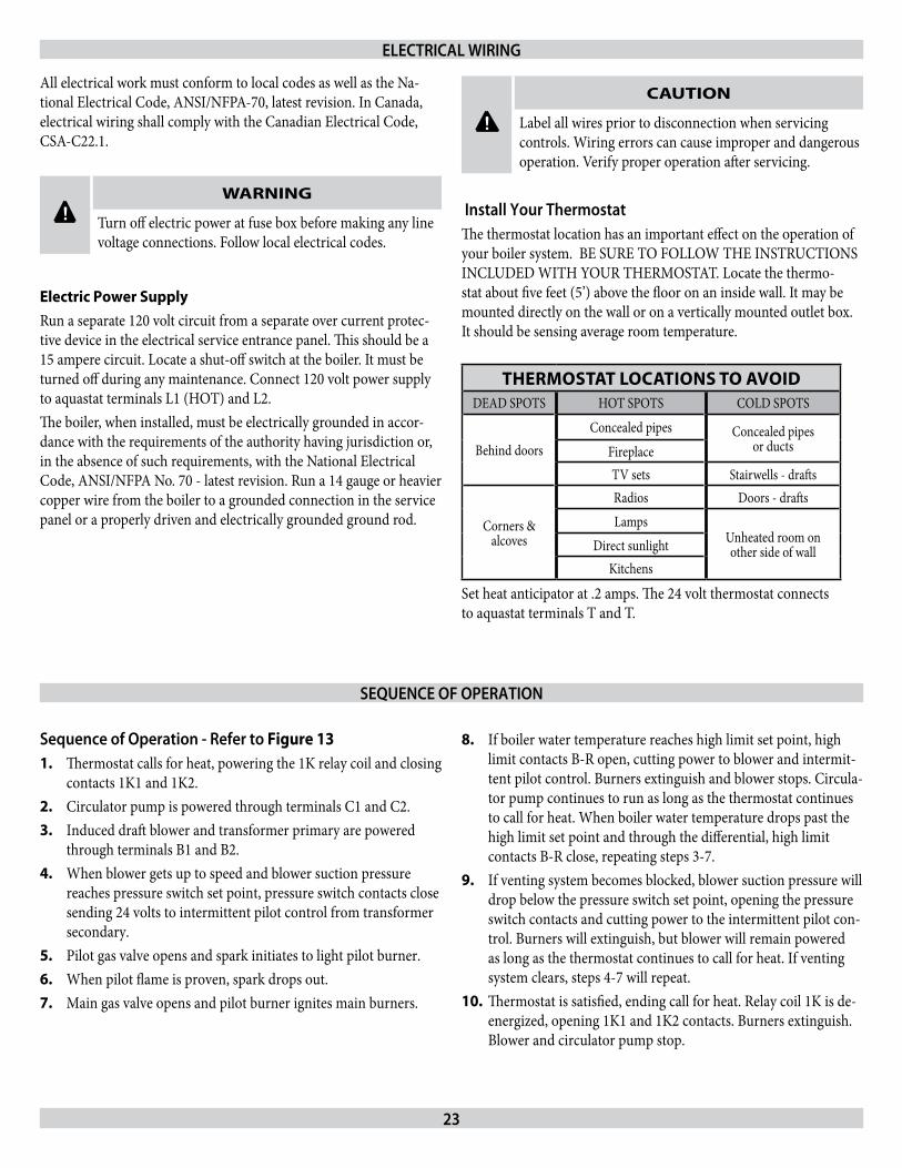
Install your ThermostatThe thermostat location has an important effect on the operation of your boiler system. BE SURE TO FOLLOW THE INSTRUCTIONS INCLUDED WITH YOUR THERMOSTAT. Locate the thermo-stat about five feet (5’) above the floor on an inside wall. It may be mounted directly on the wall or on a vertically mounted outlet box. It should be sensing average room temperature.
24
ELECTRICAL WIRING DIAGRAMS FORINDUCED DRAFT HOT WATER BOILERS
14680316 REV 5
B1
CIRCULATOR
B
C1
B
C2
W
HOTFUSEDDISCONNECT
R
B
3
L1 L2 T
NEUT
POWER SUPPLY120/60/1
24V LOW VOLTAGE FIELD WIRING
BK
GND.
BK
PV/MVSWITCH
PRESSURE ROLLOUTSWITCH W
RG PV
MV
WGR BK TO PILOT
VR8204A / VR8304MGAS VALVE
BT BL
AT 140C TRANSFORMERBT
B2
MV/
PVINTERMITTENT PILOT CONTROL
MV
(24V
)PV G
ND
.
L8148A
T
DRAFTBLUE
(GN
D.)
(24V
)
SPAR
K
BLR RED
LOW VOLTAGE WIRINGLINE VOLTAGE WIRING
BLACK WITH TRACER
GREENWHITE
BLACKBTWG
B
G
G
BW
WB
INDUCER
AQUASTAT
THERMOSTAT
BURNER
1K
(24V)
(24V)(GND)
INTERMITTENTPILOT CONTROL
PRESSURESWITCH
1K1
HIGH LIMIT
B1
R
B
31K2
T
AT 140C TRANSFORMER
24 V SECONDARY
SWITCHROLLOUT
24 V SECONDARY
120V PRIMARY
24 V THERMOSTAT
C1
T
CIRCULATOR
DRAFT INDUCER
FUSEDDISCONNECT
L1
HOT120/60/1 POWER SUPPLY
120 V PRIMARY
TO GASVALVE
B2
C2
L2
NEUT
G
B W
B W
G
B W
B
BT
WIrINg dIAgrAmS
Figure #13 - Intermittent Ignition
NOTICE
NOTE: The circulator harness is factory wired to the aquastat. This harness needs to be connected to the circu-lator in the field.
NOTICE
If any of the original wire as supplied with this appliance must be replaced, it must be replaced with type 105° C thermoplastic wire or its equivalent.
25
relief ValveYou must have a relief valve on your boiler. Water expands as it is heated. If there is no place for the water to expand into, water pres-sure will build up inside the boiler and system. Should this happen, the Relief Valve will automatically open at a pre-determined pres-sure. This will relieve the strain on the boiler and system. Run a pipe from the relief valve outlet (pipe must be same size as outlet and the open end must not be threaded) to an open drain, tub or sink, or other suitable drainage point not subject to freezing. Failure to do so may cause water damage or injury should relief valve release.
Expansion TankIn a properly assembled system, the expanding water flows into an Expansion Tank. This tank should be of the correct size.The tank is partially filled with air. As the water expands it compress-es the air in the tank to form an air pressure cushion. This “spring-like” cushion serves to maintain correct operating water pressure regardless of water temperature. This assures a “full measure” of wa-ter, even in the highest radiation unit of the system. It also prevents blowing off of the relief valve.The air in the tank in the beginning (with system filled with cold wa-ter) is sufficient for proper operation. The tank also serves as a trap for excess air in the system. The air would cause gurgling in the pipes and inefficient circulation in the radiators if left in the system.It is possible for a tank to become “waterlogged” (filled with water). It can also become overfilled with air. This can happen after filling the system with new water. Fittings provided on the tank and in the line to the tank are for bleeding off excess water or air.When installing this tank, it is important:1) That the tank be higher than the boiler top. 2) That the pipe to the tank continuously rises up to the tank (so that air can “bubble” up to it).
diaphragm Type Expansion Tank The Diaphragm Type Expansion Tank (EX-TROL) takes the place of the conventional expansion tank. Carefully read the instructions packed with your EX-TROL Tank Assembly. The EX-TROL Tank comes to you with a 10-12 pounds per square inch air charge. This is the same as the pressure produced in the system by the automatic fill valve. When the system is first filled, the EX-TROL Tank will contain little or no water.As the water is heated its pressure increases. It expands into the EX-TROL Tank, compressing the air in the tank. This compressed air cushion permits the water in the system to expand as the tempera-ture changes.
Air Eliminating Fitting (Air purger) An Air Purger is used to remove excess air from the system. It is in-stalled in the supply line. It will help to eliminate air from the water before it reaches the radiators and bleed off this air.
main Air Vent For down Flow Systems Or diaphragm Type Expansion TankBefore a system is filled with water, there is air in the pipes and radiation units. Some of it will be trapped as the system is filled. It is possible to eliminate most of this air through the air vents on the radiation units. A Main Air Vent will speed and simplify this. It should be installed on the highest point in the main when all radia-tion is below top of boiler.
Automatic Fill ValveFor safe, efficient operation, a hot water system must be filled with water. Adding new water, when needed can be done manually (by use of a hand valve in the water supply line). This requires regular at-tention to the system’s needs. An Automatic Fill Valve accomplishes this without attention. It is installed in the Supply Line on hot water boilers only. The Valve operates through water pressure differentials. It does not require an electrical connection.
drain ValveThis manual valve provides a means of draining all water from the boiler and system. It is often installed in the ¾” Tapping at the bot-tom of the left boiler section. Or it can be installed in a tee where the return line enters the boiler.
EquIpmENT & OpTIONAL ACCESSOrIES
Water Temperature ControlThe water temperature limit control in the relay is adjustable and may be set as necessary. It may be set as low as 140° F, or as high as 240° F. This depends on the type and amount of radiation involved and weather conditions.
Circulating pumpEvery Forced Hot-Water System requires a Circulating Pump. A separate pump or zone valve is required for each Zone, if you have a two or more Zone System. This pump must have the capacity to provide the circulation required by your system. The pump does not come pre-installed on the boiler. It must be con-nected to the circulator harness in the field according to the pump manufacturer’s instructions and the wiring diagrams in this manual.
26
rollout Switch(Flame Rollout Safety Shutoff)The rollout switch is a temperature-sensitive fuse link device. It is lo-cated on the boiler base just outside the fire box. In the event of heat exchanger flueway blockage causing flame to roll out of the fire box, the fuse will blow, shutting down the flow of gas to the main burners. The fuse does not change in appearance when blown.If the rollout switch blows, it must be replaced with an exact replace-ment. Check heat exchanger flueways for blockage when restoring system to operating condition. Do not operate system without a rollout switch.
EquIpmENT & OpTIONAL ACCESSOrIES
Blower (draft Inducer)The blower provides a means for pulling air through the boiler and exhausting the flue gasses into the vent system. The blower shuts off when the burners are not firing. This keeps heat in the house rather than having it go up the chimney.
pressure SwitchThe air pressure switch works on a negative pressure. When the blower comes on the air pressure switch operates the intermittent pi-lot and gas valve. The air pressure switch is factory set and will only work when the blower operates properly. It will not allow the boiler to come on if the blower does not generate enough pressure or if the venting system is blocked.
Factory pressure Switch Set point: -0.4” wc. for 2-5 section boilers.-0.5” w.c. for 6-7 section boilers.

27
How A Hot Water System OperatesYour entire heating system (boiler, piping and radiation units) is filled with water. As the water in the boiler is heated, it is pumped from the top of the boiler through the supply main to the radia-tion units. The cooler water in them flows back through the return main to the boiler. This provides positive and rapid response to the thermostat.
Filling System With WaterClose the Air Vents on all radiation units. Open the Valves to these units. Make sure the boiler and Expansion Tank Drain Cocks are closed. The Air Bleed Screw on the tank Drain Fitting should be closed. Open the valve in the line from the boiler to the expansion tank. Open the water inlet to your boiler and leave it open. Start with the lowest radiation unit. Open the air vent on this unit. When all the air has escaped and water starts to flow from the vent, close it. Go to the next radiation unit, and repeat this process. Repeat until you have covered every radiation unit in the system (ending up at the highest unit in the system). If your units have automatic vents, this manual venting is unnecessary but it will speed up the proper filling of your system.If your system is a closed expansion tank system, you may have an Automatic Fill Valve. You may leave it open to refill the system au-tomatically as needed. Check the temperature-pressure gauge. Note the position of the hand indicating pressure. This should be between 10 and 15 lbs. Any lowering of this movable hand below 10 lbs. will indicate loss of water due to leakage. The automatic fill valve should compensate for this. Instructions are packaged with the valve.
STArTINg yOur BOILEr
! WARNING
Never run water into a hot empty boiler.
!
WARNING
This appliance is equipped with an ignition device which automatically lights the burner. Do not attempt to light the burner by hand.
If you do not follow these instructions exactly, fire or ex-plosion may result with property damage, personal injury, or loss of life.
BEFORE OPERATING smell all around the appliance area for gas. Be sure to smell next to the floor because some gas is heavier than air and will settle on the floor.
IF YOU SMELL GAS:Do not attempt to operate any appliance, do not 1. touch any electrical switch, do not use the phone.Leave the building immediately and call your gas 2. supplier.If your gas supplier cannot be reached, call the fire 3. department.
When turning or depressing the gas control knob, use only your hand to push down or turn the knob. Never use tools. If the knob will not operate by hand, the control must be replaced by a qualified service technician. Force or at-tempted repair may result in a fire or explosion.
If any part of this appliance has been under water, do not operate. Immediately call a qualified service technician to inspect the appliance and to replace any part of the gas control system which has been under water.
28
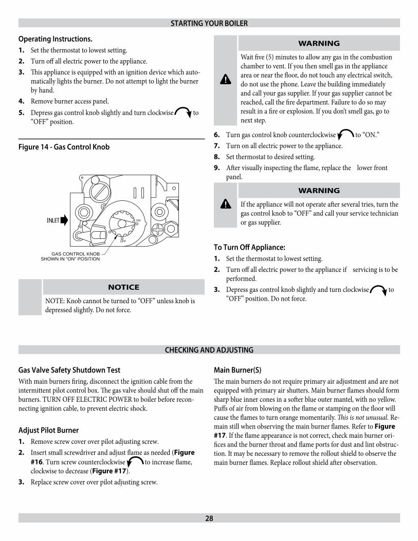
Operating Instructions. Set the thermostat to lowest setting.1. Turn off all electric power to the appliance.2. This appliance is equipped with an ignition device which auto-3. matically lights the burner. Do not attempt to light the burner by hand.Remove burner access panel.4. Depress gas control knob slightly and turn clockwise 5. to “OFF” position.
OFF
ONINLET
GAS CONTROL KNOBSHOWN IN "ON" POSITION
gas Valve Safety Shutdown TestWith main burners firing, disconnect the ignition cable from the intermittent pilot control box. The gas valve should shut off the main burners. TURN OFF ELECTRIC POWER to boiler before recon-necting ignition cable, to prevent electric shock.
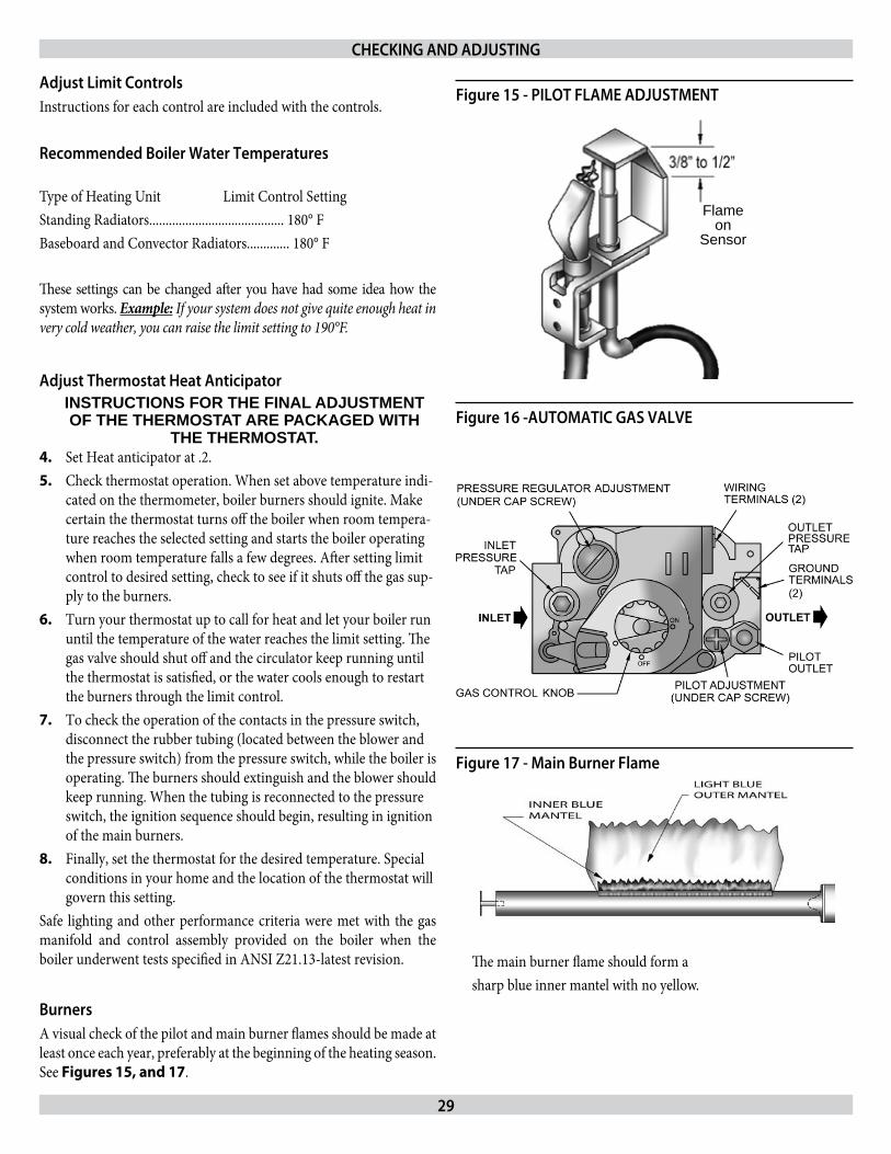
Adjust pilot BurnerRemove screw cover over pilot adjusting screw.1. Insert small screwdriver and adjust flame as needed (2. Figure #16. Turn screw counterclockwise to increase flame, clockwise to decrease (Figure #17).Replace screw cover over pilot adjusting screw.3.
main Burner(S)The main burners do not require primary air adjustment and are not equipped with primary air shutters. Main burner flames should form sharp blue inner cones in a softer blue outer mantel, with no yellow. Puffs of air from blowing on the flame or stamping on the floor will cause the flames to turn orange momentarily. This is not unusual. Re-main still when observing the main burner flames. Refer to Figure #17. If the flame appearance is not correct, check main burner ori-fices and the burner throat and flame ports for dust and lint obstruc-tion. It may be necessary to remove the rollout shield to observe the main burner flames. Replace rollout shield after observation.
!
WARNING
Wait five (5) minutes to allow any gas in the combustion chamber to vent. If you then smell gas in the appliance area or near the floor, do not touch any electrical switch, do not use the phone. Leave the building immediately and call your gas supplier. If your gas supplier cannot be reached, call the fire department. Failure to do so may result in a fire or explosion. If you don’t smell gas, go to next step.
Turn gas control knob counterclockwise 6. to “ON.” Turn on all electric power to the appliance.7. Set thermostat to desired setting.8. After visually inspecting the flame, replace the lower front 9. panel.
! WARNING
If the appliance will not operate after several tries, turn the gas control knob to “OFF” and call your service technician or gas supplier.
To Turn Off Appliance:Set the thermostat to lowest setting.1. Turn off all electric power to the appliance if servicing is to be 2. performed.Depress gas control knob slightly and turn clockwise 3. to “OFF” position. Do not force.
STArTINg yOur BOILEr
CHECKINg ANd AdjuSTINg
Figure 14 - gas Control Knob
NOTICE
NOTE: Knob cannot be turned to “OFF” unless knob is depressed slightly. Do not force.
29
Adjust Limit ControlsInstructions for each control are included with the controls.
recommended Boiler Water Temperatures Type of Heating Unit Limit Control SettingStanding Radiators......................................... 180° FBaseboard and Convector Radiators............. 180° F
These settings can be changed after you have had some idea how the system works. Example: If your system does not give quite enough heat in very cold weather, you can raise the limit setting to 190°F.
Adjust Thermostat Heat Anticipator INSTRUCTIONS FOR THE FINAL ADJUSTMENT OF THE THERMOSTAT ARE PACKAGED WITH
THE THERMOSTAT. Set Heat anticipator at .2.4. Check thermostat operation. When set above temperature indi-5. cated on the thermometer, boiler burners should ignite. Make certain the thermostat turns off the boiler when room tempera-ture reaches the selected setting and starts the boiler operating when room temperature falls a few degrees. After setting limit control to desired setting, check to see if it shuts off the gas sup-ply to the burners. Turn your thermostat up to call for heat and let your boiler run 6. until the temperature of the water reaches the limit setting. The gas valve should shut off and the circulator keep running until the thermostat is satisfied, or the water cools enough to restart the burners through the limit control.To check the operation of the contacts in the pressure switch, 7. disconnect the rubber tubing (located between the blower and the pressure switch) from the pressure switch, while the boiler is operating. The burners should extinguish and the blower should keep running. When the tubing is reconnected to the pressure switch, the ignition sequence should begin, resulting in ignition of the main burners.Finally, set the thermostat for the desired temperature. Special 8. conditions in your home and the location of the thermostat will govern this setting.
Safe lighting and other performance criteria were met with the gas manifold and control assembly provided on the boiler when the boiler underwent tests specified in ANSI Z21.13-latest revision.
BurnersA visual check of the pilot and main burner flames should be made at least once each year, preferably at the beginning of the heating season. See Figures 15, and 17.
CHECKINg ANd AdjuSTINg
Flameon
Sensor
Figure 15 - pILOT FLAmE AdjuSTmENT
Figure 16 -AuTOmATIC gAS VALVE
The main burner flame should form a sharp blue inner mantel with no yellow.
Figure 17 - main Burner Flame
30
INITIAL OpErATIONAL BOILEr TEST CHECK-OuT prOCEdurE
☑ Check off each step as completed. ☐ Verify base insulation is securely fastened to base panels.☐ Verify air purged from hydronic heating system.☐ Purge air from gas piping; check gas piping for leaks.☐ Verify proper orifices have been installed.☐ Follow lighting instructions in series XEB installation, operation and maintenance manual furnished with boiler.☐ Visually check the main burner flame and verify it has a well defined inner blue mantel with a lighter blue outer mantel.☐ Inspect vent system to verify it is functional, unobstructed, and not leaking.☐ Test the temperature limit control: With burner operating, adjust indicator on limit control below actual boiler water temperature. Verify burners turn off. Verify the circulator continues to operate. Adjust the indicator on limit control above actual boiler water temperature and verify burners reignite. ☐ Test any additional field-installed controls. If boiler has a low water cut-off or additional high limit, test for operation as outlined by the controls manufacturer. Burners should be operating and should go off when controls are tested. When controls are reset, burners should reignite.☐ Test safety control circuit: with main burner operating, disconnect the ignition cable from the intermittent pilot control box. Verify that the main gas control closes, shutting off the gas to the main burner. After verify ing safety control circuit, turn off electric power and reconnect ignition cable. Once ignition cable securely reset to intermittent pilot control box, turn electric power on. ☐ For multiple heating system zones, balance flow through each zone so that it is about equal per zone.☐ Verify several operating cycles of proper operation.☐ Measure gas input:
Natural Gas Procedure☐ Operate boiler for 10 minutes.☐ Turn off all other gas appliances piped with the boiler. ☐ At the gas meter, measure the cubic feet of gas used in 10 seconds (CF10).☐ Calculate input: BTUh = CF10 x 360,000☐ Verify the BTUh is approximate to the input rating on the boiler rating plate.
LP Gas Procedure☐ LP gas input rate is determined by measuring gases produced during combustion. Refer to Boiler Manual for combustion guidelines and corresponding BTU input.☐ Verify the BTUh is approximate to the input rating on the boiler rating plate.
☐ Record the BTUh input on the OPERATIONAL BOILER TEST CERTIFICATE & SIGNED RECEIPT form.☐ Set operating control (thermostat(s)) to the desired design requirement.☐ Forward boiler manuals, instructions, wiring diagrams, piping diagrams, and supporting information shipped with this boiler to owner and/or maintenance personnel. ☐ Complete and sign the INITIAL OPERATIONAL BOILER TEST CERTIFICATE & SIGNED RECEIPT form.
XEB Series Cast Iron gas-Fired Cast Iron Boilers
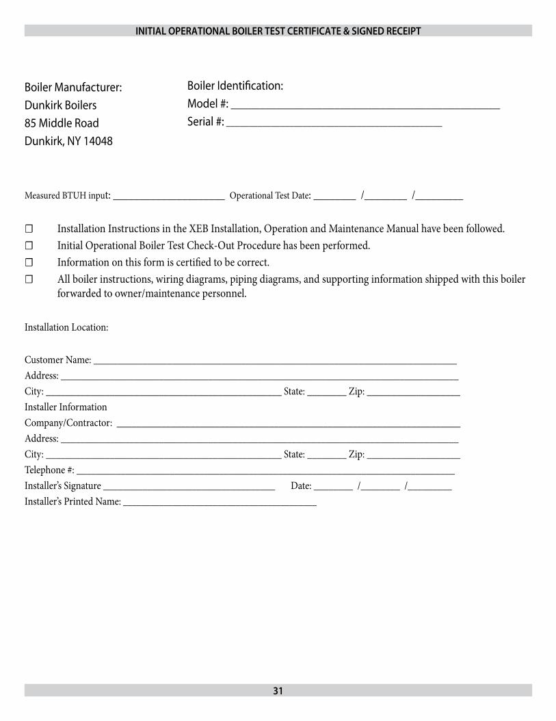
31
INITIAL OpErATIONAL BOILEr TEST CErTIFICATE & SIgNEd rECEIpT
Measured BTUH input: _____________________ Operational Test Date: ________ /________ /_________
☐ Installation Instructions in the XEB Installation, Operation and Maintenance Manual have been followed.☐ Initial Operational Boiler Test Check-Out Procedure has been performed.☐ Information on this form is certified to be correct.☐ All boiler instructions, wiring diagrams, piping diagrams, and supporting information shipped with this boiler forwarded to owner/maintenance personnel.
Installation Location:
Customer Name: __________________________________________________________________________Address: _________________________________________________________________________________City: ________________________________________________ State: ________ Zip: ___________________Installer InformationCompany/Contractor: ______________________________________________________________________Address: _________________________________________________________________________________City: ________________________________________________ State: ________ Zip: ___________________Telephone #: _____________________________________________________________________________Installer’s Signature ___________________________________ Date: ________ /________ /_________Installer’s Printed Name: ___________________________________________
Boiler Manufacturer:Dunkirk Boilers85 Middle RoadDunkirk, NY 14048
Boiler Identification:Model #: _______________________________________________Serial #: ________________________________________________

32
relief ValveThis valve should open automatically if the system pressure exceeds the pressure rating (usually 30 psi) of the relief valve. Should it ever fail to open under this condition, shut down your system. Drain the system until system pressure is reduced below the relief valve pressure rating. If valve discharge occurs, or if valve fails to open as described above, contact an authorized contractor or qualified service technician to replace the relief valve and inspect the heating system to determine the cause, as this may indicate an equipment malfunction.This valve should be tested every month during periods of boiler operation, and at the beginning and end of any extended non-service period. Prior to testing, make certain discharge pipe is properly connected to valve outlet and arranged so as to contain and safely dispose of boiler discharge. Test at normal system operating pres-sure. Hold the trip lever fully open for at least five seconds in order to flush free any sediment that may lodge on the valve seat. Then permit the valve to snap shut.
Expansion TankAs previously noted, this tank may become waterlogged, or may re-ceive an excess of air. Frequent automatic opening of the relief valve indicates water logging. A high boiler temperature accompanied by unusually low radiation unit temperature (and “knocking”) indicates excess air in tank. To correct either condition, close the valve be-tween the boiler and the tank. Drain the tank until it is empty. Check all the tank plugs and fittings. Tighten as necessary. Open the valve between the boiler and tank. Water will rise to the normal height in the tank if you have an automatic fill valve (otherwise, manually refill the system).
Boiler Flue passagesUnder normal operating conditions, with the burners properly adjusted, it should not be necessary to clean the boiler flue gas pas-sages. However, to assure trouble-free operation, we recommend that you have the flue passages, burner adjustment, and operation of the controls checked once each year by a competent Service Technician.
Before The Start Of Each Season(or whenever system has been shut down for some time) recheck the whole system for leaks . . . and recheck the boiler and vent pipe for leaks. Replace or patch any boiler seals that are faulty.
Vent pipeThe venting of this unit is very important and the piping should be checked at least once a month. If the vent piping shows any sign of leaking, replace it immediately.
Water SystemIf system is to remain out of service during freezing weather, always drain it completely (water left in to freeze will crack the pipes and/or boiler).
Cleaning your Boiler And BurnersFlue passages between sections should be examined yearly and cleaned if necessary. To clean, remove burners, pilot and vent pipe. Remove top and front jacket panels. Split the silicone seal on the flue collector and the clean out plates with a razor knife. Remove flue collector. Remove clean out plates by tapping upwards on the bottom of the plate with a hammer. Remove loose silicone sealant from sections, flue collector, and clean out plates. Clean passageways between sections with a flexible handle wire brush and a straightened out wire coat hanger. Remove dirt from the bottom of the boiler and from between sections by vacuuming. Make sure all flame ports in burners are open and clear. Shake out or blow out all loose dirt in burners. Reassemble all parts. Seal flue collector and clean out plates to sections with silicone sealant (400° F RTV silicone sealant or equivalent). Reseal seams between adjacent sections where necessary. All joints must be airtight. Be sure to check tightness of pilot connections and condition of burner flames after reassembly (see Figures 15, and 17). Be sure vent pipe connec-tions to chimney are secure and no obstructions are present.
BlowerThe blower motor features a permanently lubricated ball bearing construction. Lubrication is not required.
Circulator pump Isolation ValvesThe isolation valves in the circulator pump flanges should be oper-ated manually once or twice per year to prevent the valves from be-coming stuck in the open position. Rotate the valves from the open position to the closed position and back to the open position.
mAINTAININg yOur BOILEr
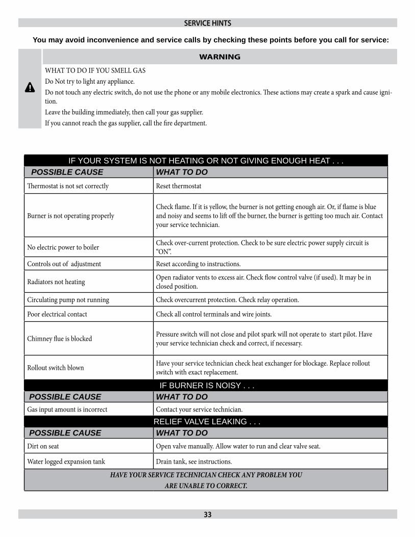
33
You may avoid inconvenience and service calls by checking these points before you call for service:
IF YOUR SYSTEM IS NOT HEATING OR NOT GIVING ENOUGH HEAT . . .POSSIBLE CAUSE WHAT TO DO
Thermostat is not set correctly Reset thermostat
Burner is not operating properlyCheck flame. If it is yellow, the burner is not getting enough air. Or, if flame is blue and noisy and seems to lift off the burner, the burner is getting too much air. Contact your service technician.
No electric power to boiler Check over-current protection. Check to be sure electric power supply circuit is “ON”.
Controls out of adjustment Reset according to instructions.
Radiators not heating Open radiator vents to excess air. Check flow control valve (if used). It may be in closed position.
Circulating pump not running Check overcurrent protection. Check relay operation.
Poor electrical contact Check all control terminals and wire joints.
Chimney flue is blocked Pressure switch will not close and pilot spark will not operate to start pilot. Have your service technician check and correct, if necessary.
Rollout switch blown Have your service technician check heat exchanger for blockage. Replace rollout switch with exact replacement.
IF BURNER IS NOISY . . . POSSIBLE CAUSE WHAT TO DO
Gas input amount is incorrect Contact your service technician.
RELIEF VALVE LEAKING . . .POSSIBLE CAUSE WHAT TO DO
Dirt on seat Open valve manually. Allow water to run and clear valve seat.
Water logged expansion tank Drain tank, see instructions.
HAVE YOUR SERVICE TECHNICIAN CHECK ANY PROBLEM YOU ARE UNABLE TO CORRECT.
SErVICE HINTS
!
WARNING
WHAT TO DO IF YOU SMELL GASDo Not try to light any appliance.Do not touch any electric switch, do not use the phone or any mobile electronics. These actions may create a spark and cause igni-tion.Leave the building immediately, then call your gas supplier.If you cannot reach the gas supplier, call the fire department.

34

35

85 Middle Rd.Dunkirk, NY 14048