gas insulated metal-enclosed switchgear sf6 circuit ... · pdf filemedium voltage distribution...
TRANSCRIPT
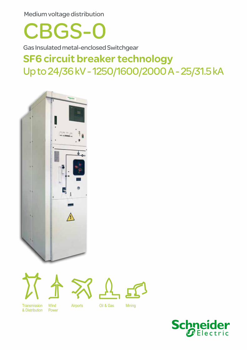
Medium voltage distribution
CBGS-0 Gas Insulated metal-enclosed Switchgear
SF6 circuit breaker technology Up to 24/36 kV - 1250/1600/2000 A - 25/31.5 kA
Oil & Gas MiningAirportsTransmission& Distribution
Wind Power
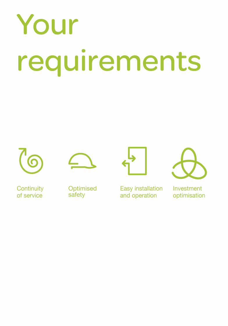
Your requirements
Continuity of service
Optimised safety
Easy installation and operation
Investment optimisation
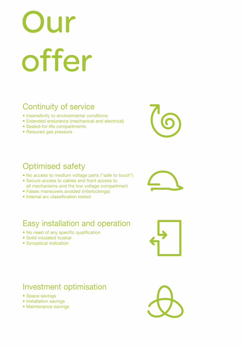
Our offerContinuity of service• Insensitivity to environmental conditions• Extended endurance (mechanical and electrical)• Sealed-for-life compartments• Reduced gas pressure
Optimised safety• No access to medium voltage parts ("safe to touch")• Secure access to cables and front access to
all mechanisms and the low voltage compartment• Falses maneuvers avoided (interlockings)• Internal arc classification tested
Easy installation and operation• No need of any specific qualification• Solid insulated busbar• Synoptical indication
Investment optimisation• Space savings• Installation savings• Maintenance savings
Standards compliancy● IEC 62271-1: Common clauses for
high voltage switchgear standards.● IEC 62271-100: High voltage alternating
current circuit breakers.● IEC 62271-200: Metal-enclosed switchgear
for alternating current at rated voltages between 1 and 52 kV.
● IEC 62271-102: High voltage AC disconnectors and earthing switches.
● IEC 62271-103: Switches for rated voltages above 1 and less than 52 kV.
● IEC 62271-105: High voltage alternating current switch-fuse combinations.
● IEC 60044-1: Current transformers.● IEC 60044-2: Voltage transformers.● ANSI: CBGS-0 according to ANSI,
please contact us.
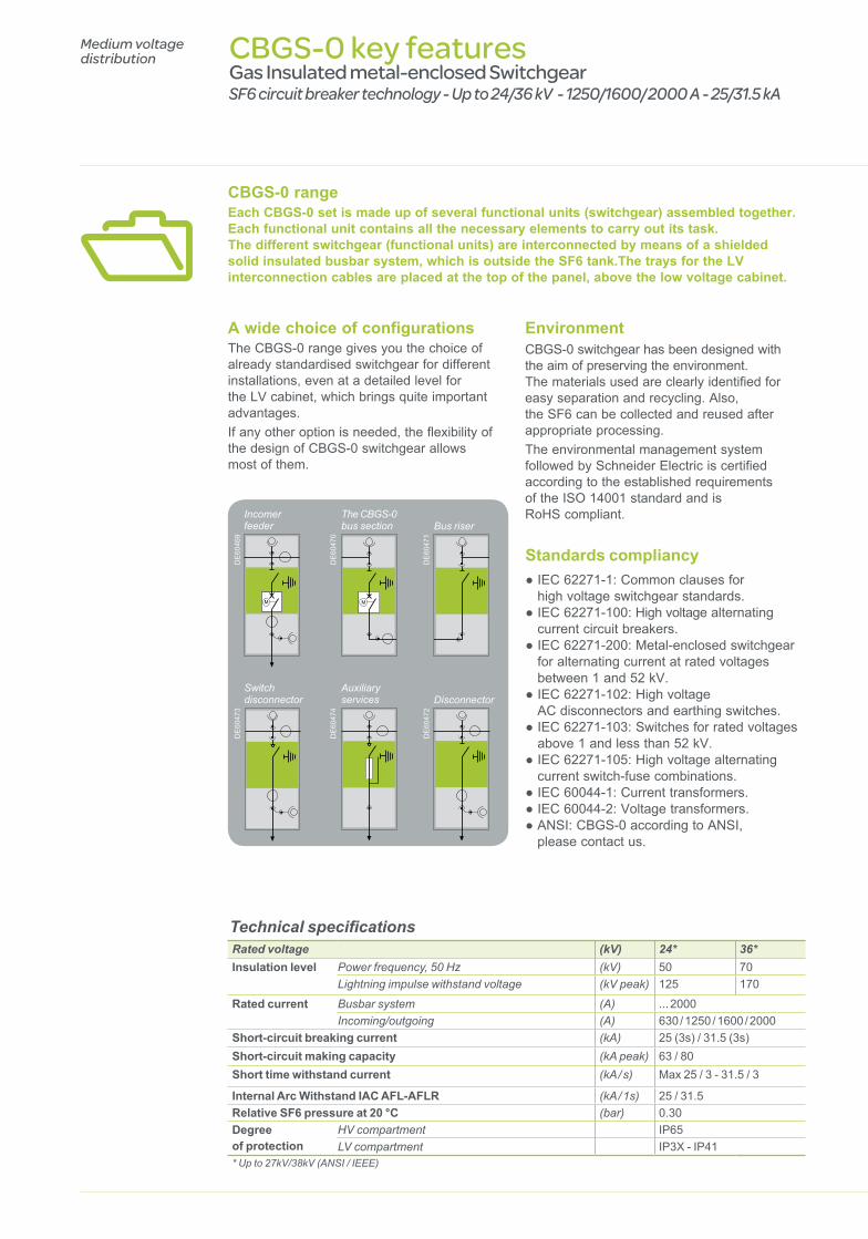
CBGS-0 key featuresGas Insulated metal-enclosed SwitchgearSF6 circuit breaker technology - Up to 24/36 kV - 1250/1600/ 2000 A - 25/31.5 kA
Medium voltage distribution
CBGS-0 rangeEach CBGS-0 set is made up of several functional units (switchgear) assembled together. Each functional unit contains all the necessary elements to carry out its task. The different switchgear (functional units) are interconnected by means of a shielded solid insulated busbar system, which is outside the SF6 tank.The trays for the LV interconnection cables are placed at the top of the panel, above the low voltage cabinet.
A wide choice of configurationsThe CBGS-0 range gives you the choice of already standardised switchgear for different installations, even at a detailed level for the LV cabinet, which brings quite important advantages. If any other option is needed, the flexibility of the design of CBGS-0 switchgear allows most of them.
EnvironmentCBGS-0 switchgear has been designed with the aim of preserving the environment. The materials used are clearly identified for easy separation and recycling. Also, the SF6 can be collected and reused after appropriate processing. The environmental management system followed by Schneider Electric is certified according to the established requirements of the ISO 14001 standard and is RoHS compliant.
Technical specificationsRated voltage (kV) 24* 36*Insulation level Power frequency, 50 Hz (kV) 50 70
Lightning impulse withstand voltage (kV peak) 125 170
Rated current Busbar system (A) ... 2000Incoming/outgoing (A) 630 / 1250 / 1600 / 2000
Short-circuit breaking current (kA) 25 (3s) / 31.5 (3s)Short-circuit making capacity (kA peak) 63 / 80Short time withstand current (kA / s) Max 25 / 3 - 31.5 / 3
Internal Arc Withstand IAC AFL-AFLR (kA / 1s) 25 / 31.5Relative SF6 pressure at 20 °C (bar) 0.30Degree of protection
HV compartment IP65LV compartment IP3X - IP41
* Up to 27kV/38kV (ANSI / IEEE)
Incomerfeeder
Switch disconnector
The CBGS-0 bus section
DisconnectorAuxiliary services
DE
6046
9D
E60
473
DE
6047
0D
E60
474
Bus riser
DE
6047
1D
E60
472
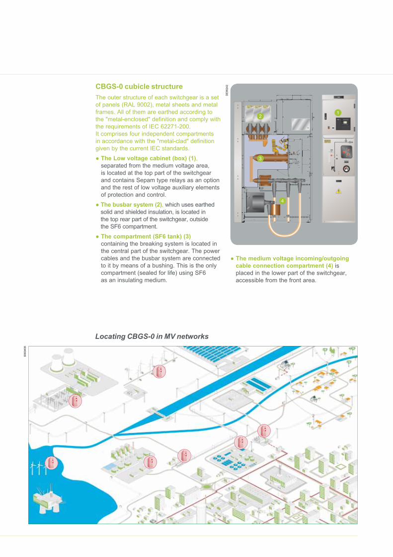
CBGS-0 cubicle structureThe outer structure of each switchgear is a set of panels (RAL 9002), metal sheets and metal frames. All of them are earthed according to the "metal-enclosed" definition and comply with the requirements of IEC 62271-200. It comprises four independent compartments in accordance with the "metal-clad" definition given by the current IEC standards.
● The Low voltage cabinet (box) (1), separated from the medium voltage area, is located at the top part of the switchgear and contains Sepam type relays as an option and the rest of low voltage auxiliary elements of protection and control.
● The busbar system (2), which uses earthed solid and shielded insulation, is located in the top rear part of the switchgear, outside the SF6 compartment.
● The compartment (SF6 tank) (3) containing the breaking system is located in the central part of the switchgear. The power cables and the busbar system are connected to it by means of a bushing. This is the only compartment (sealed for life) using SF6 as an insulating medium.
21
3
4
DE
9024
2
● The medium voltage incoming/outgoing cable connection compartment (4) is placed in the lower part of the switchgear, accessible from the front area.
Locating CBGS-0 in MV networks
E00
3435
Continuity of service● Insensitivity to ambient conditions - Sealed for life SF6 compartment: routine tested. - Service life >30 years. The hermetic nature
of the tank (primary enclosure) ensures the protection of the switchgear against external agents such as dirt, dust, insects, rodents, etc.
● Extended endurance (mechanical and electrical)
- Lower distances/dimensions due to SF6 insulation.
- Minimum energy required.● Sealed-for-life compartments If the appropiate cable terminals are used,
CBGS-0 switchgear can neither be affected
Highly confirmed quality • At present, more than 10,000 switchgear units of the CBGS type have already been installed. • In compliance with ISO 9000, ISO 14000 and OSHAS, our factories have 18,000 certificates for their quality and environmental management systems. • Fully factory-tested equipment, also with type test reports available for each switchgear version.
Medium voltage distribution CBGS-0 key benefits
Gas Insulated metal-enclosed SwitchgearSF6 circuit breaker technology - Up to 24/36 kV - 1250/1600/ 2000 A - 25/31.5 kA
by moisture or dirt nor by corrosive or polluted operating environments, since all high voltage parts are provided with shielded solid insulation (busbar system) or are contained in the SF6-filled tank, which is sealed for life.
● Reduced SF6 pressure● High repairability - The circuit breaker operating mechanism is
accessible from the outside of the SF6 tank (primary enclosure).
- Voltage transformers are inductive type, metal enclosed for plug-in and assembled outside the SF6 tank.
- Current transformers are toroidal-core type and are also located outside the SF6 tank.
DE
6047
9
PE90591 PE90590 PE90589
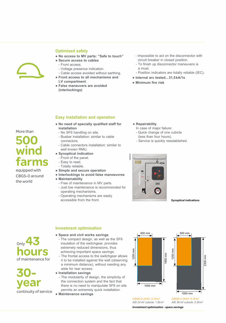
Investment optimisation● Space and civil works savings
- The compact design, as well as the SF6 insulation of the switchgear, provides extremely reduced dimensions, thus achieving important space savings.
- The frontal access to the switchgear allows it to be installed against the wall (observing a minimum distance), without needing any aisle for rear access.
● Installation savings - The modularity of design, the simplicity of
the connection system and the fact that there is no need to manipulate SF6 on site permits an extremely quick installation.
● Maintenance savings
Investment optimisation - space savings
CBGS-0 24 kV: 0.75 m2
AIS 24 kV cubicle: 1.95 m2
CBGS-0 36 kV: 0.75 m2
AIS 36 kV cubicle: 2.30 m2
1250
mm
1250
mm
1950
mm
2300
mm
2300
mm
600 mm 600 mm
1000 mm
1000 mm
Optimised safety● No access to MV parts: “Safe to touch”● Secure access to cables
- Front access. - Voltage presence indication. - Cable access avoided without earthing.
● Front access to all mechanisms and LV compartment
● False maneuvers are avoided (interlockings)
- Impossible to act on the disconnector with circuit breaker in closed position.
- To finish up disconnector maneuvers is a must.
- Position indicators are totally reliable (IEC).● Internal arc tested... 31,5 kA/1s● Minimum fire risk
Easy installation and operation● No need of specially qualified staff for
installation - No SF6 handling on site. - Busbar installation: similar to cable
connectors. - Cable connectors installation: similar to
well known RMU.● Synoptical indication
- Front of the panel. - Easy to read. - Totally reliable.
● Simple and secure operation● Interlockings to avoid false manoeuvres● Maintainability
- Free of maintenance in MV parts. - Just low maintenance is recommended for
operating mechanisms. - Operating mechanisms are easily
accessible from the front.
More than
500 wind farms equipped with CBGS-0 around the world
30- year continuity of service
Only 43 hours of maintenance for
● Repairability In case of major failure: - Quick change of one cubicle
(less than four hours). - Service is quickly reestablished.
Synoptical indications
DE
9024
3
Schneider Electric Industries SASHead Office35, rue Joseph MonierCS 3032392506 Rueil-Malmaisonwww.schneider-electric.com
As standards, specifications and designs change from time to time, please ask for confirmation of the information given in this publication.
Publishing: SYNTHESE ECA, Schneider Electric.Photos: Schneider Electric
03/2012
AR
T838
863
- ©
Sch
neid
er E
lect
ric In
dus
trie
s S
AS
- A
ll rig
hts
rese
rved
.
998-4382_GMA-GB - NRJED112384EN
CBGS-0: more than 10,000 units already installed throughout the world
● Transmission & Distribution: Iberdrola Endesa Scottish Power NEC RG&E CMP NYSEG
● Wind power: GAMESA Iberdrola Renovables GE Wind Vestas Suzlon Nordex Enercon
● Airports: Madrid Airport Barcelona Airport Bilbao Airport Lisboa Airport
● Trains: Barcelona Underground ADIF High Speed Trains Eurotunnel Suburban Train
● Oil & Gas: REPSOL ARAMCO TOTAL
● Mining: Koniambo Aznalcollar
PE
9058
6M
WP
0042
889
PE
9007
5P
E90
380
AYP
0700
844
PE
9020
6
Medium voltage distribution