gas insulated substation
TRANSCRIPT
SEMINAR PRESENTATION TOPIC:
GAS INSULATED SUBSTATIONS SESSION:2014-2015
PRESENTED BY:
NAME:MOHAMMAD SAIF BRANCH:ELECTRICAL AND ELECTRONICS ENGG.
1
Contents Introduction of GIS
Gas Insulated Substation
Internal equipments of GIS.
Definitions of equipments.
Internal equipments of GIS.
Need of GIS
Service condition of GIS
Services offered by GIS to supplier.
Drawback of GIS.
Advantages of GIS.
Application of GIS .
Conclusion.
References
Introduction to GIS
GIS was first developed in various countries between 1968 and 1972.
After about 5 years of experience, the use rate increased to about 20% of new substations in countries where space is limited.
Conventional substations requires, small installations size, protection against atmosphere pollution and moisture, noiseless operation, on explosive and flame resistant, reduced maintenance, minimal radio interference, but totally enclosed substations using SF6 gas as insulation that are also known as GIS which is stand for GAS INSULATED SUBSTATIONS.
GIS is now in widespread use in the electrical power industry.
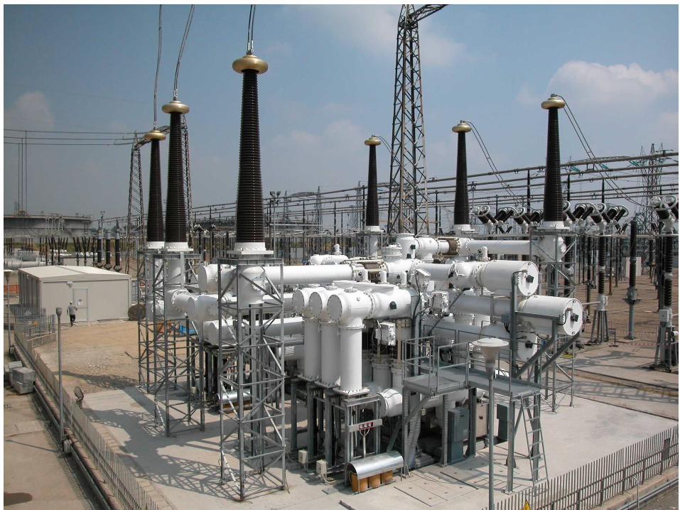
GAS INSULATED SUBSTATIONS
Definition: A gas insulated substation(GIS) is a substation that uses a
superior dielectric gas, sulfur hexafluoride (SF6),high voltage.
The basic principle of GIS equipment:
Is that the high-voltage current carrying parts are within a metal enclosure and are held in a concentric configuration by cast epoxy spacer insulators.
The space between the conductor and the enclosure is filled with SF6 gas under moderate pressure.
GAS INSULATED SUBSTATIONS
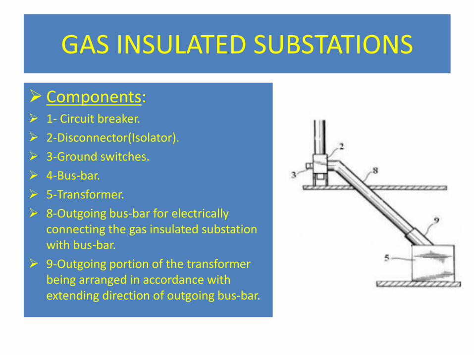
Components: 1- Circuit breaker.
2-Disconnector(Isolator).
3-Ground switches.
4-Bus-bar.
5-Transformer.
8-Outgoing bus-bar for electrically connecting the gas insulated substation with bus-bar.
9-Outgoing portion of the transformer being arranged in accordance with extending direction of outgoing bus-bar.
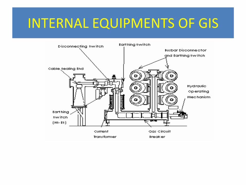
INTERNAL EQUIPMENTS OF GIS
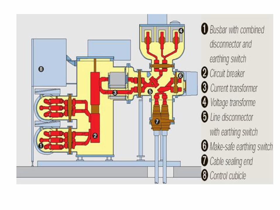
Definition's of equipment's
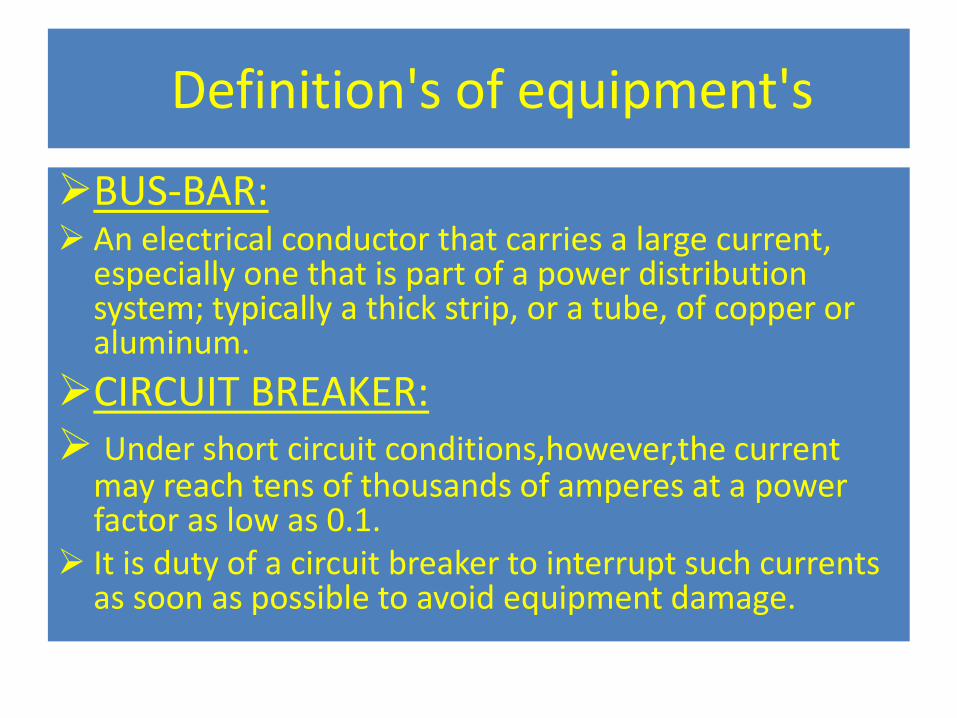
BUS-BAR: An electrical conductor that carries a large current,
especially one that is part of a power distribution system; typically a thick strip, or a tube, of copper or aluminum.
CIRCUIT BREAKER: Under short circuit conditions,however,the current
may reach tens of thousands of amperes at a power factor as low as 0.1.
It is duty of a circuit breaker to interrupt such currents as soon as possible to avoid equipment damage.
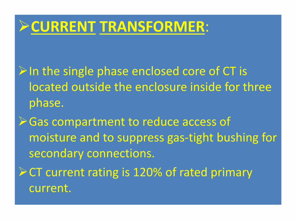
CURRENT TRANSFORMER:
In the single phase enclosed core of CT is
located outside the enclosure inside for three phase.
Gas compartment to reduce access of moisture and to suppress gas-tight bushing for secondary connections.
CT current rating is 120% of rated primary current.
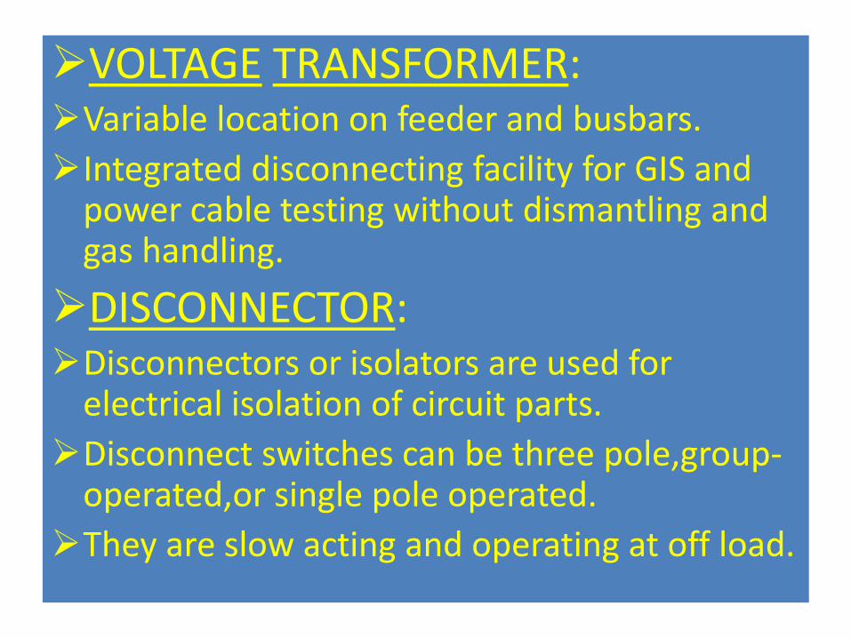
VOLTAGE TRANSFORMER: Variable location on feeder and busbars.
Integrated disconnecting facility for GIS and power cable testing without dismantling and gas handling.
DISCONNECTOR: Disconnectors or isolators are used for
electrical isolation of circuit parts.
Disconnect switches can be three pole,group-operated,or single pole operated.
They are slow acting and operating at off load.
EARTHING SWITCH:
Slow operating earthing switch are used for protection purpose.
When work is being done in the substation, but are operated only when it is certain that the high-voltage system is not energized.
The fast closing earthing switch can close against full voltage and short circuit power.
The high speed earthing switch is achieved by means of a spring-closing device.
CABLES COMPARTMENT:
Optimized solution for plug-in type power cable
connection.
Adjustable support structure for minimum requirements for the GIS floor.
Fixation to the GIS floor by cemented anchor bolts, no need for special foundation (steel beams….etc.)
LOCAL CONTROL CUBICLE: LCC is the interface cubicles to all secondary system of a substation which
are represent a station control and protection.
LCC includes control and alarm functions as well as the correct distribution of auxiliary power supply for the relevant GIS .
In general, each cabinet should contain the following equipment for control, indication and protection of switches, circuit breaker, and associated components:
1. One control switch for each three phase circuit breaker.
2. One remote local switch for each three phase circuit breaker.
3. One open close control switch for each motor operated grounding switch.
4. One or two red light-emitting diodes and one green for each circuit breaker, each disconnect and grounding switch, or contact position indication .
5. Control switches for ac and dc supply to each compartment.
Need for GIS
Non availability of sufficient space.
Reduction in length of feeders.
Improvement of the quality of voltage regulation due to short length feeder.
Total space required for GIS is 10% of the needed for a conventional substation.
GIS technology can be used for installations in areas where the cost of real estates is appreciable.
Overcome or decrease the magnitude of limitation of AIS site selection.
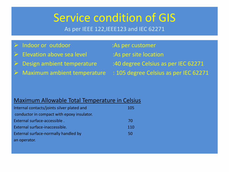
Service condition of GIS As per IEEE 122,IEEE123 and IEC 62271
Indoor or outdoor :As per customer
Elevation above sea level :As per site location
Design ambient temperature :40 degree Celsius as per IEC 62271
Maximum ambient temperature : 105 degree Celsius as per IEC 62271
Maximum Allowable Total Temperature in Celsius Internal contacts/joints silver plated and 105
conductor in compact with epoxy insulator.
External surface-accessible . 70
External surface-inaccessible. 110
External surface-normally handled by 50
an operator.
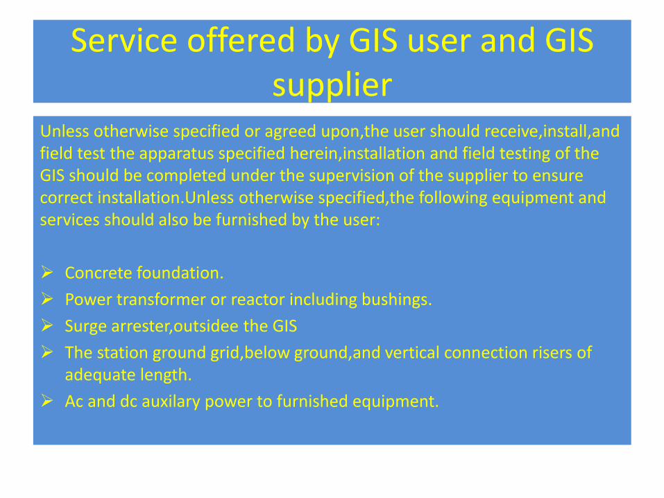
Service offered by GIS user and GIS supplier
Unless otherwise specified or agreed upon,the user should receive,install,and field test the apparatus specified herein,installation and field testing of the GIS should be completed under the supervision of the supplier to ensure correct installation.Unless otherwise specified,the following equipment and services should also be furnished by the user:
Concrete foundation.
Power transformer or reactor including bushings.
Surge arrester,outsidee the GIS
The station ground grid,below ground,and vertical connection risers of adequate length.
Ac and dc auxilary power to furnished equipment.
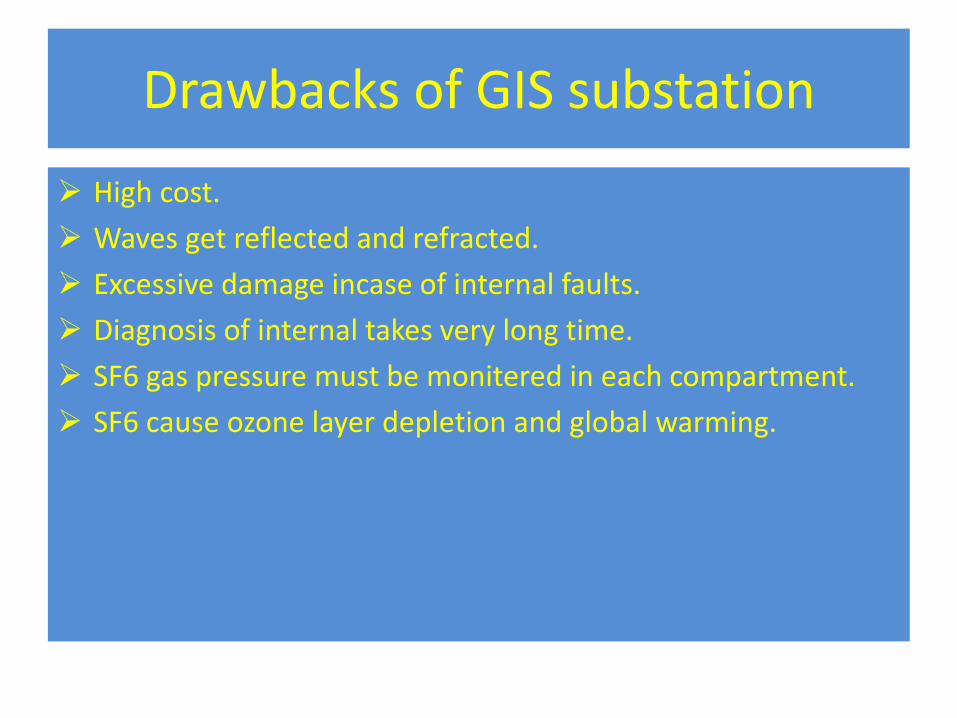
Drawbacks of GIS substation
High cost.
Waves get reflected and refracted.
Excessive damage incase of internal faults.
Diagnosis of internal takes very long time.
SF6 gas pressure must be monitered in each compartment.
SF6 cause ozone layer depletion and global warming.
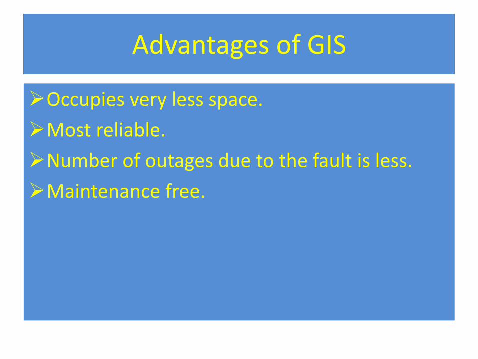
Advantages of GIS
Occupies very less space.
Most reliable.
Number of outages due to the fault is less.
Maintenance free.
Applications of GIS
High voltage installations
The higher the voltage, the more favorable gas insulated technology becomes. The
footprint of 765kV conventional substation is enormous, and GIS technology allows a
significant size reduction. Urban Installations
GIS technology can be used for installations in areas where the cost of real estate or aesthetic appeal is a significant consideration. Indoor Installations
Building an air insulated substation indoors is usually impractical, but a GIS can easily go inside buildings. Environmentally Sensitive Installations
GIS technology is popular in desert and arctic areas because it can be enclosed in a building with environmental control.
Conclusion
GIS generate no noise and have no idea no radio interference.
GIS is necessary for extra HV and Ultra HV substations.
More conservative.
Reference
• www.google.com/gasinsulatedsubstation
• www.yahoo.com/gasinsulatedsubstation
• www.slideshare.com/gasinsulatedsubstation
Thanking you