(gas / lpg) (sn/ 008000 rider scrubber english en...
TRANSCRIPT
T20
*9016200*
(SN/ 008000− )Rider Scrubber
English ENOperator Manual
9016200Rev. 00 (08-2016)
(Gas / LPG)
The Safe Scrubbing Alternative�
ES� Extended Scrub SystemTennantTrue� Parts
Hygenic� Fully Cleanable TanksFloorSmart� Integrated Cleaning System
IRIS� a Tennant TechnologyPro−Panel� ControlsInsta−Fit� Adapter
North America / InternationalFor the latest Parts manuals and otherlanguage Operator manuals, visit:
www.tennantco.com/manuals
�
INTRODUCTION
This manual is furnished with each new model. It provides necessary operation and maintenance instructions.
Read this manual completely and understand the machine before operating or servicing it.
This machine will provide excellent service. However, the best results will be obtained at minimum costs if:
� The machine is operated with reasonable care.
� The machine is maintained regularly - per the machine maintenance instructions provided.
� The machine is maintained with manufacturer supplied or equivalent parts.
Model No. −
Serial No. −
Installation Date −
Please fill out at time of installation
for future reference.
MACHINE DATAPROTECT THE ENVIRONMENT
Please dispose of packagingmaterials, used componentssuch as batteries and fluids inan environmentally safe wayaccording to local wastedisposal regulations.
Always remember to recycle.
INTENDED USE
The T20 is an industrial rider machine designed to scrub hard surfaces (concrete, asphalt, stone, synthetic, etc).Typical applications include industrial warehouses, manufacturing facilities, distribution facilities, stadiums, arenas,convention centers, parking facilities, transportation terminals, and construction sites. Do not use this machine on soil,grass, artificial turf, or carpeted surfaces. Do not use where excessive debris is present such as leaves, paper, etc.This machine can be used both indoors and outdoors, but ensure there is adequate ventilation if used indoors. Thismachine is not intended for use on public roadways. Do not use this machine other than described in this OperatorManual.
Tennant CompanyPO Box 1452Minneapolis, MN 55440Phone: (800) 553−8033 or (763) 513−2850www.tennantco.com
CALIFORNIA PROPOSITION 65 WARNING: Engine exhaust from this product contains chemicals known to the State of California to cause cancer,birth defects, or other reproductive harm.
PerformanceView, Pro−ID, Pro−Check, Zone Settings, Thermo−Sentry, Touch−N−Go, 1−STEP, Clean−Wedge, Variable Drain Valve, EasyOpen, Grip−n−Go, MaxPro, Dura−Track, SmartRelease, InstantAccess, Duramer, FaST−PAK, ErgoSpace, and Lower Total Cost of Ownership are trademarksof Tennant Company.
Specifications and parts are subject to change without notice.
Original Instructions, copyright � 2016 TENNANT Company, Printed in U.S.A.
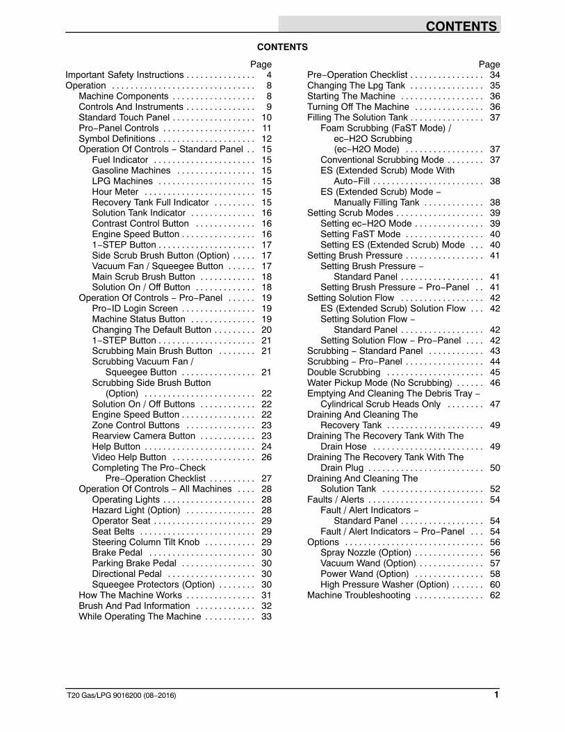
CONTENTS
1T20 Gas/LPG 9016200 (08−2016)
CONTENTS
PageImportant Safety Instructions 4. . . . . . . . . . . . . . .Operation 8. . . . . . . . . . . . . . . . . . . . . . . . . . . . . . .
Machine Components 8. . . . . . . . . . . . . . . . . .Controls And Instruments 9. . . . . . . . . . . . . . .Standard Touch Panel 10. . . . . . . . . . . . . . . . . .Pro−Panel Controls 11. . . . . . . . . . . . . . . . . . . .Symbol Definitions 12. . . . . . . . . . . . . . . . . . . . .Operation Of Controls − Standard Panel 15. .
Fuel Indicator 15. . . . . . . . . . . . . . . . . . . . . .Gasoline Machines 15. . . . . . . . . . . . . . . . .LPG Machines 15. . . . . . . . . . . . . . . . . . . . .Hour Meter 15. . . . . . . . . . . . . . . . . . . . . . . .Recovery Tank Full Indicator 15. . . . . . . . .Solution Tank Indicator 16. . . . . . . . . . . . . .Contrast Control Button 16. . . . . . . . . . . . .Engine Speed Button 16. . . . . . . . . . . . . . . .1−STEP Button 17. . . . . . . . . . . . . . . . . . . . .Side Scrub Brush Button (Option) 17. . . . .Vacuum Fan / Squeegee Button 17. . . . . .Main Scrub Brush Button 18. . . . . . . . . . . .Solution On / Off Button 18. . . . . . . . . . . . .
Operation Of Controls − Pro−Panel 19. . . . . .Pro−ID Login Screen 19. . . . . . . . . . . . . . . .Machine Status Button 19. . . . . . . . . . . . . .Changing The Default Button 20. . . . . . . . .1−STEP Button 21. . . . . . . . . . . . . . . . . . . . .Scrubbing Main Brush Button 21. . . . . . . .Scrubbing Vacuum Fan /
Squeegee Button 21. . . . . . . . . . . . . . . .Scrubbing Side Brush Button
(Option) 22. . . . . . . . . . . . . . . . . . . . . . . .Solution On / Off Buttons 22. . . . . . . . . . . .Engine Speed Button 22. . . . . . . . . . . . . . . .Zone Control Buttons 23. . . . . . . . . . . . . . .Rearview Camera Button 23. . . . . . . . . . . .Help Button 24. . . . . . . . . . . . . . . . . . . . . . . .Video Help Button 26. . . . . . . . . . . . . . . . . .Completing The Pro−Check
Pre−Operation Checklist 27. . . . . . . . . .Operation Of Controls − All Machines 28. . . .
Operating Lights 28. . . . . . . . . . . . . . . . . . . .Hazard Light (Option) 28. . . . . . . . . . . . . . .Operator Seat 29. . . . . . . . . . . . . . . . . . . . . .Seat Belts 29. . . . . . . . . . . . . . . . . . . . . . . . .Steering Column Tilt Knob 29. . . . . . . . . . .Brake Pedal 30. . . . . . . . . . . . . . . . . . . . . . .Parking Brake Pedal 30. . . . . . . . . . . . . . . .Directional Pedal 30. . . . . . . . . . . . . . . . . . .Squeegee Protectors (Option) 30. . . . . . . .
How The Machine Works 31. . . . . . . . . . . . . . .Brush And Pad Information 32. . . . . . . . . . . . .While Operating The Machine 33. . . . . . . . . . .
PagePre−Operation Checklist 34. . . . . . . . . . . . . . . .Changing The Lpg Tank 35. . . . . . . . . . . . . . . .Starting The Machine 36. . . . . . . . . . . . . . . . . .Turning Off The Machine 36. . . . . . . . . . . . . . .Filling The Solution Tank 37. . . . . . . . . . . . . . . .
Foam Scrubbing (FaST Mode) / ec−H2O Scrubbing (ec−H2O Mode) 37. . . . . . . . . . . . . . . . .
Conventional Scrubbing Mode 37. . . . . . . .ES (Extended Scrub) Mode With
Auto−Fill 38. . . . . . . . . . . . . . . . . . . . . . . .ES (Extended Scrub) Mode −
Manually Filling Tank 38. . . . . . . . . . . . .Setting Scrub Modes 39. . . . . . . . . . . . . . . . . . .
Setting ec−H2O Mode 39. . . . . . . . . . . . . . .Setting FaST Mode 40. . . . . . . . . . . . . . . . .Setting ES (Extended Scrub) Mode 40. . .
Setting Brush Pressure 41. . . . . . . . . . . . . . . . .Setting Brush Pressure −
Standard Panel 41. . . . . . . . . . . . . . . . . .Setting Brush Pressure − Pro−Panel 41. .
Setting Solution Flow 42. . . . . . . . . . . . . . . . . .ES (Extended Scrub) Solution Flow 42. . .Setting Solution Flow −
Standard Panel 42. . . . . . . . . . . . . . . . . .Setting Solution Flow − Pro−Panel 42. . . .
Scrubbing − Standard Panel 43. . . . . . . . . . . .Scrubbing − Pro−Panel 44. . . . . . . . . . . . . . . . .Double Scrubbing 45. . . . . . . . . . . . . . . . . . . . .Water Pickup Mode (No Scrubbing) 46. . . . . .Emptying And Cleaning The Debris Tray −
Cylindrical Scrub Heads Only 47. . . . . . . .Draining And Cleaning The
Recovery Tank 49. . . . . . . . . . . . . . . . . . . . .Draining The Recovery Tank With The
Drain Hose 49. . . . . . . . . . . . . . . . . . . . . . . .Draining The Recovery Tank With The
Drain Plug 50. . . . . . . . . . . . . . . . . . . . . . . . .Draining And Cleaning The
Solution Tank 52. . . . . . . . . . . . . . . . . . . . . .Faults / Alerts 54. . . . . . . . . . . . . . . . . . . . . . . . .
Fault / Alert Indicators − Standard Panel 54. . . . . . . . . . . . . . . . . .
Fault / Alert Indicators − Pro−Panel 54. . .Options 56. . . . . . . . . . . . . . . . . . . . . . . . . . . . . .
Spray Nozzle (Option) 56. . . . . . . . . . . . . . .Vacuum Wand (Option) 57. . . . . . . . . . . . . .Power Wand (Option) 58. . . . . . . . . . . . . . .High Pressure Washer (Option) 60. . . . . . .
Machine Troubleshooting 62. . . . . . . . . . . . . . .

CONTENTS
T20 Gas/LPG 9016200(08−2016)2
PageMaintenance 64. . . . . . . . . . . . . . . . . . . . . . . . . . . . .
Maintenance Chart 65. . . . . . . . . . . . . . . . . . . .Yellow Touch Points 68. . . . . . . . . . . . . . . . . . . .Lubrication 68. . . . . . . . . . . . . . . . . . . . . . . . . .
Engine Oil 68. . . . . . . . . . . . . . . . . . . . . . . . .Squeegee Caster Bearings 68. . . . . . . . . .Front Wheel Support Bearing 68. . . . . . . . .Steering Cylinder Bearing 68. . . . . . . . . . . .Rear Wheel Bearings 69. . . . . . . . . . . . . . .Torque Tubes−Cylindrical Brushes 69. . . .Torque Tubes−Disk Brushes 69. . . . . . . . .Pivot Shaft−Disk Brushes 69. . . . . . . . . . . .
Hydraulics 70. . . . . . . . . . . . . . . . . . . . . . . . . .Hydraulic Fluid 71. . . . . . . . . . . . . . . . . . . . .Hydraulic Hoses 71. . . . . . . . . . . . . . . . . . . .
Engine 72. . . . . . . . . . . . . . . . . . . . . . . . . . . . . . .Cooling System 72. . . . . . . . . . . . . . . . . . . .Air Filter 73. . . . . . . . . . . . . . . . . . . . . . . . . .Fuel Filter (LPG) 73. . . . . . . . . . . . . . . . . . . .LPG Vaporizer 73. . . . . . . . . . . . . . . . . . . . .Fuel Filter (Gasoline) 73. . . . . . . . . . . . . . . .Engine Belt 74. . . . . . . . . . . . . . . . . . . . . . . .PCV System 74. . . . . . . . . . . . . . . . . . . . . . .Spark Plugs − Mitsubishi Engines 74. . . . .Camshaft And Balance Shaft Belts −
Mitsubishi Engines 74. . . . . . . . . . . . . . .Battery 74. . . . . . . . . . . . . . . . . . . . . . . . . . . . . . .Fuses And Relays 75. . . . . . . . . . . . . . . . . . . . .
Relay Panel Fuses And Relays 75. . . . . . .Engine Harness Fuses And Relays 76. . .Optional Relays 76. . . . . . . . . . . . . . . . . . . .Circuit Breakers (ec−H2O) 76. . . . . . . . . . .
Scrub Brushes And Pads 76. . . . . . . . . . . . . . .Disk Brushes 76. . . . . . . . . . . . . . . . . . . . . . .Replacing Disk Brushes Or
Pad Driver 77. . . . . . . . . . . . . . . . . . . . . .Replacing Disk Pads 78. . . . . . . . . . . . . . . .Checking The Disk Scrub Head
Stop Bumpers 78. . . . . . . . . . . . . . . . . . .Cylindrical Brushes 79. . . . . . . . . . . . . . . . .Replacing Or Rotating Cylindrical
Brushes 79. . . . . . . . . . . . . . . . . . . . . . . .Checking Cylindrical Brush Pattern 80. . . .Adjusting The Cylindrical
Brush Taper 81. . . . . . . . . . . . . . . . . . . . .Adjusting The Cylindrical
Brush Width 81. . . . . . . . . . . . . . . . . . . . .Side Brush (Option) 82. . . . . . . . . . . . . . . . . . . .
Replacing The Side Brush 82. . . . . . . . . . .
PageFaST System 83. . . . . . . . . . . . . . . . . . . . . . . . .
Replacing The FaST−PAK Carton 83. . . . .Cleaning The FaST Supply Hose
Connector 84. . . . . . . . . . . . . . . . . . . . . .Cleaning The FaST System Filter
Screen 84. . . . . . . . . . . . . . . . . . . . . . . . .Replacing The Fast System Filters 84. . . .
ec−H2O Module Flush Procedure 85. . . . . . . .Cleaning The ec−H2O Filter Screen 86. . . . . .Squeegee Blades 87. . . . . . . . . . . . . . . . . . . . . .
Replacing (Or Rotating) The Rear Squeegee Blades 87. . . . . . . . . . . . . . . .
Replacing Or Rotating The Side Squeegee Blades 89. . . . . . . . . . . . . . . .
Replacing Or Adjusting The Side Brush Squeegee Blade (Option) 91. . .
Leveling The Rear Squeegee 92. . . . . . . . .Adjusting The Rear Squeegee
Blade Deflection 93. . . . . . . . . . . . . . . . .Skirts And Seals 94. . . . . . . . . . . . . . . . . . . . . . .
Scrub Head Skirt 94. . . . . . . . . . . . . . . . . . .Recovery Tank Seal 94. . . . . . . . . . . . . . . . .Solution Tank Seals 94. . . . . . . . . . . . . . . . .
Brakes And Tires 95. . . . . . . . . . . . . . . . . . . . . .Brakes 95. . . . . . . . . . . . . . . . . . . . . . . . . . . .Tires 95. . . . . . . . . . . . . . . . . . . . . . . . . . . . . .Front Wheel 95. . . . . . . . . . . . . . . . . . . . . . .
Propelling Motor 95. . . . . . . . . . . . . . . . . . . . . . .Pushing, Towing, And Transporting
The Machine 96. . . . . . . . . . . . . . . . . . . . . . .Pushing Or Towing The Machine 96. . . . . .Transporting The Machine 96. . . . . . . . . . .
Machine Jacking 98. . . . . . . . . . . . . . . . . . . . . .Storage Information 98. . . . . . . . . . . . . . . . . . . .
Freeze Protection (Machines Without ec−H2O System) 99. . . . . . . . . . . . . . . .
Freeze Protection (Machines With ec−H2O System) 99. . . . . . . . . . . . . . . .
Priming The ec−H2O System 101. . . . . . .Specifications 102. . . . . . . . . . . . . . . . . . . . . . . . . . .
General Machine Dimensions/Capacities 102General Machine Performance 102. . . . . . . . .Hydraulic System 103. . . . . . . . . . . . . . . . . . . . .Braking System 103. . . . . . . . . . . . . . . . . . . . . .Tires 103. . . . . . . . . . . . . . . . . . . . . . . . . . . . . . . .Steering 103. . . . . . . . . . . . . . . . . . . . . . . . . . . . .FaST System 104. . . . . . . . . . . . . . . . . . . . . . . .ec−H2O System 104. . . . . . . . . . . . . . . . . . . . . .Machine Dimensions 105. . . . . . . . . . . . . . . . . .
CONTENTS
3T20 Gas/LPG 9016200 (08−2016)
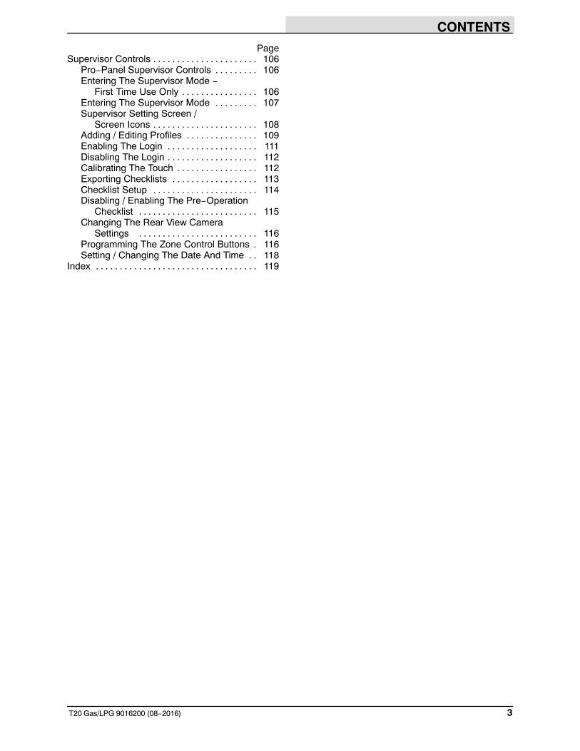
PageSupervisor Controls 106. . . . . . . . . . . . . . . . . . . . . .
Pro−Panel Supervisor Controls 106. . . . . . . . .Entering The Supervisor Mode −
First Time Use Only 106. . . . . . . . . . . . . . . .Entering The Supervisor Mode 107. . . . . . . . .Supervisor Setting Screen /
Screen Icons 108. . . . . . . . . . . . . . . . . . . . . .Adding / Editing Profiles 109. . . . . . . . . . . . . . .Enabling The Login 111. . . . . . . . . . . . . . . . . . .Disabling The Login 112. . . . . . . . . . . . . . . . . . .Calibrating The Touch 112. . . . . . . . . . . . . . . . .Exporting Checklists 113. . . . . . . . . . . . . . . . . .Checklist Setup 114. . . . . . . . . . . . . . . . . . . . . .Disabling / Enabling The Pre−Operation
Checklist 115. . . . . . . . . . . . . . . . . . . . . . . . .Changing The Rear View Camera
Settings 116. . . . . . . . . . . . . . . . . . . . . . . . .Programming The Zone Control Buttons 116.Setting / Changing The Date And Time 118. .
Index 119. . . . . . . . . . . . . . . . . . . . . . . . . . . . . . . . . .
SAFETY PRECAUTIONS
T20 Gas/LPG 9016200 (08−2016)4
IMPORTANT SAFETY INSTRUCTIONS − SAVE THESE INSTRUCTIONS
The following precautions are used throughoutthis manual as indicated in their description:
WARNING: To warn of hazards orunsafe practices that could result insevere personal injury or death.
CAUTION: To warn of unsafe practicesthat could result in minor or moderatepersonal injury.
FOR SAFETY: To identify actions that must befollowed for safe operation of equipment.
The following information signals potentiallydangerous conditions to the operator. Know whenthese conditions can exist. Locate all safetydevices on the machine. Report machinedamage or faulty operation immediately.
WARNING: Flammable materials cancause an explosion or fire. Do not useflammable materials in tank.
WARNING: Flammable materials orreactive metals can cause an explosionor fire. Do not pickup.
WARNING: Moving belt and fan. Keepaway.
WARNING: Engine emits toxic gases.Serious injury or death can result.Provide adequate ventilation.
WARNING: Burn hazard. Hot surface. DoNOT touch.
CAUTION: LPG engine will run for afew seconds after key is turned off.Apply parking brake before leavingmachine.
WARNING: Do not spray people oranimals. Severe personal injury canresult. Wear eye protection. Holdsprayer with two hands.
WARNING: This machine containschemicals known to the State ofCalifornia to cause cancer, birth defects,or other reproductive harm.
This machine may be equipped withtechnology that automatically communicatesover the cellular network. If this machine willbe operated where cell phone use is restrictedbecause of concerns related to equipmentinterference, please contact a Tennantrepresentative for information on how todisable the cellular communicationfunctionality.
FOR SAFETY:
1. Do not operate machine:− Unless trained and authorized.− Unless operator manual is read and
understood.− Under the influence of alcohol or
drugs.− While using a cell phone or other
types of electronic devices.− In dusty environments without the
vacuum fan on.− Without filters in place or with clogged
filters.− Unless mentally and physically
capable of following machineinstructions.
− If it is not in proper operatingcondition.
− With pads or accessories not suppliedor approved by Tennant. The use ofother pads may impair safety.
− In areas where flammablevapors/liquids or combustible dustsare present.
− In areas that are too dark to safely seethe controls or operate the machineunless operating / headlights areturned on.
− In areas with possible falling objectsunless equipped with overhead guard.
2. Before starting machine:− Check for fuel, oil, and liquid leaks.− Keep sparks and open flame away
from refueling area.− Make sure all safety devices are in
place and operate properly.− Check brakes and steering for proper
operation.− Adjust seat and fasten seat belt.
3. When starting machine:− Keep foot on brake and directional
pedal in neutral.
SAFETY PRECAUTIONS
5T20 Gas/LPG 9016200 (08−2016)
4. When using machine:− Use only as described in this manual.− Use brakes to stop machine.− Do not pick up burning or smoking
debris, such as cigarettes, matches orhot ashes
− Go slowly on inclines and slipperysurfaces.
− Do not scrub on ramp inclines thatexceed 10% grade or transport(GVWR) on ramp inclines that exceed14% grade.
− Reduce speed when turning.− Keep all parts of body inside operator
station while machine is moving.− Always be aware of surroundings
while operating machine.− Do not access the video / help screens
while the machine is moving.(Pro−Panel).
− Use care when reversing machine.− Keep children and unauthorized
persons away from machine.− Do not carry passengers on machine.− Always follow safety and traffic rules.− Report machine damage or faulty
operation immediately.− Follow mixing, handling and disposal
instructions on chemical containers.− Follow safety guidlines concerning
wet floors.
5. Before leaving or servicing machine:− Do not park near combustible
materials, dusts, gases, or liquids.− Stop on level surface.− Set parking brake.− Turn off machine and remove key.
6. When servicing machine:− All work must be done with sufficient
lighting and visibility.− Keep work area well ventilated.− Avoid moving parts. Do not wear loose
clothing, jewelry and secure long hair.− Block machine tires before jacking
machine up.− Jack machine up at designated
locations only. Support machine withjack stands.
− Use hoist or jack that will support theweight of the machine.
− Do not push or tow the machinewithout an operator in the seatcontrolling the machine.
− Do not power spray or hose offmachine near electrical components.
− Disconnect battery connections beforeworking on machine.
− Avoid contact with battery acid.− Avoid contact with hot engine coolant.− Do not remove cap from radiator when
engine is hot.− Allow engine to cool.− Keep flames and sparks away from
fuel system service area. Keep areawell ventilated.
− Use cardboard to locate leakinghydraulic fluid under pressure.
− All repairs must be performed by atrained service mechanic.
− Do not modify the machine from itsoriginal design.
− Use Tennant supplied or approvedreplacement parts.
− Wear personal protective equipmentas needed and where recommended inthis manual.
For Safety: wear hearing protection.
For Safety: wear protective gloves.
For Safety: wear eye protection.
For Safety: wear protective dust mask.
7. When loading/unloading machineonto/off truck or trailer:− Drain tanks before loading machine.− Lower scrub head and squeegee
before tying down machine.− Turn off machine and remove key.− Use ramp, truck or trailer that will
support the weight of the machine andoperator.
− Do not load/unload on ramp inclinesthat exceed 18% grade.
− Use winch. Do not drive the machineonto/off the truck or trailer unless theload height is 380 mm (15 in) or lessfrom the ground.
− Set parking brake after machine isloaded.
− Block machine tires.− Tie machine down to truck or trailer.
SAFETY PRECAUTIONS
T20 Gas/LPG 9016200 (08−2016)6
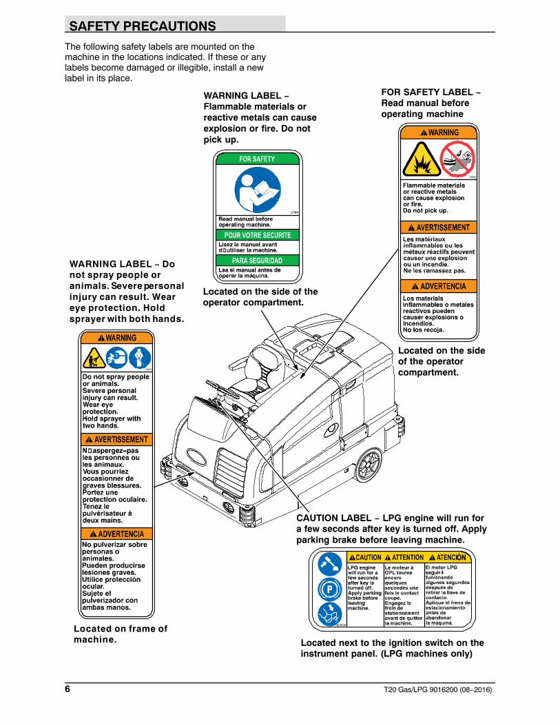
The following safety labels are mounted on themachine in the locations indicated. If these or anylabels become damaged or illegible, install a newlabel in its place.
Located on the sideof the operatorcompartment.
Located on the side of theoperator compartment.
Located next to the ignition switch on theinstrument panel. (LPG machines only)
Located on frame ofmachine.
WARNING LABEL −Flammable materials orreactive metals can causeexplosion or fire. Do notpick up.
WARNING LABEL − Donot spray people oranimals. Severe personalinjury can result. Weareye protection. Holdsprayer with both hands.
FOR SAFETY LABEL −Read manual beforeoperating machine
CAUTION LABEL − LPG engine will run fora few seconds after key is turned off. Applyparking brake before leaving machine.
SAFETY PRECAUTIONS
7T20 Gas/LPG 9016200 (08−2016)
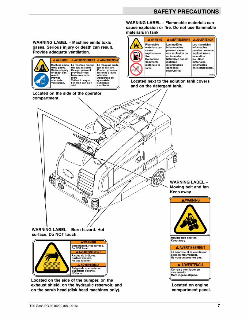
Located on the side of the bumper, on theexhaust shield, on the hydraulic reservoir, andon the scrub head (disk head machines only).
Located on enginecompartment panel.
Located on the side of the operatorcompartment.
WARNING LABEL − Machine emits toxicgases. Serious injury or death can result.Provide adequate ventilation.
WARNING LABEL − Flammable materials cancause explosion or fire. Do not use flammablematerials in tank.
Located next to the solution tank coversand on the detergent tank.
WARNING LABEL − Burn hazard. Hotsurface. Do NOT touch
WARNING LABEL −Moving belt and fan.Keep away.
OPERATION
8 T20 Gas/LPG 9016200 (08−2016)
OPERATION
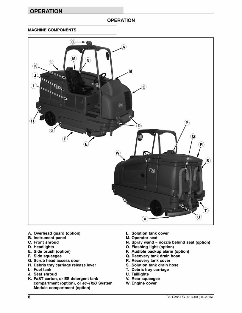
MACHINE COMPONENTS
S
R
T
U
P
V
Q
W
C
G
F
KB
A
E
D
L
I
M
H
N
J
O
A. Overhead guard (option)B. Instrument panelC. Front shroudD. HeadlightsE. Side brush (option)F. Side squeegeeG. Scrub head access doorH. Debris tray carriage release leverI. Fuel tankJ. Seat shroudK. FaST carton, or ES detergent tank
compartment (option), or ec−H2O System Module compartment (option)
L. Solution tank coverM. Operator seatN. Spray wand − nozzle behind seat (option)O. Flashing light (option)P. Audible backup alarm (option)Q. Recovery tank drain hoseR. Recovery tank coverS. Solution tank drain hoseT. Debris tray carriageU. TaillightsV. Rear squeegeeW. Engine cover
OPERATION
9T20 Gas/LPG 9016200 (08−2016)
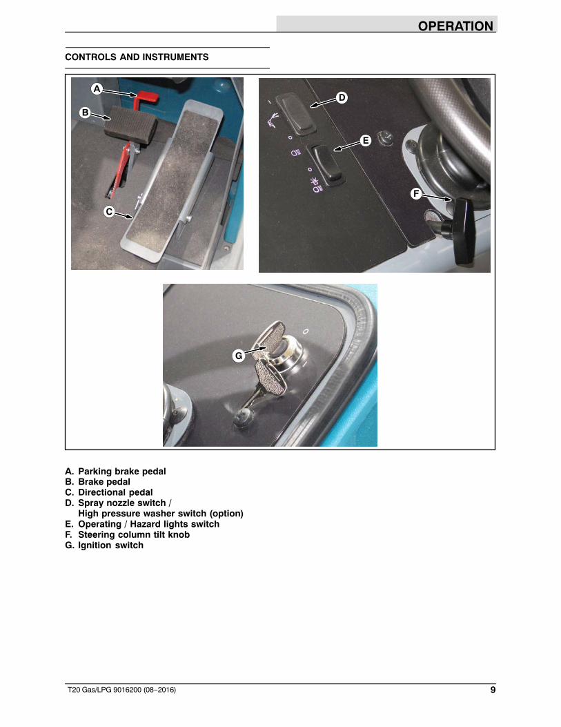
CONTROLS AND INSTRUMENTS
A
B
C
G
D
F
E
A. Parking brake pedalB. Brake pedalC. Directional pedalD. Spray nozzle switch /
High pressure washer switch (option)E. Operating / Hazard lights switchF. Steering column tilt knobG. Ignition switch
OPERATION
10 T20 Gas/LPG 9016200 (08−2016)
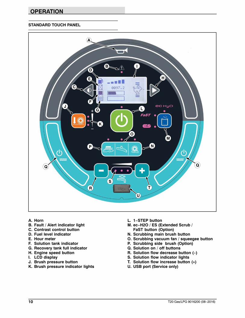
STANDARD TOUCH PANEL
A
B
C
D
E
F
G
H
I
J
K
L
M
N
O
P
Q Q
R
S
T
U
A. HornB. Fault / Alert indicator lightC. Contrast control buttonD. Fuel level indicatorE. Hour meterF. Solution tank indicatorG. Recovery tank full indicatorH. Engine speed buttonI. LCD displayJ. Brush pressure buttonK. Brush pressure indicator lights
L. 1−STEP buttonM. ec−H2O / ES (Extended Scrub /
FaST button (Option)N. Scrubbing main brush buttonO. Scrubbing vacuum fan / squeegee buttonP. Scrubbing side brush (Option)Q. Solution on / off buttonsR. Solution flow decrease button (−)S. Solution flow indicator lightsT. Solution flow increase button (+)U. USB port (Service only)
OPERATION
11T20 Gas/LPG 9016200 (08−2016)
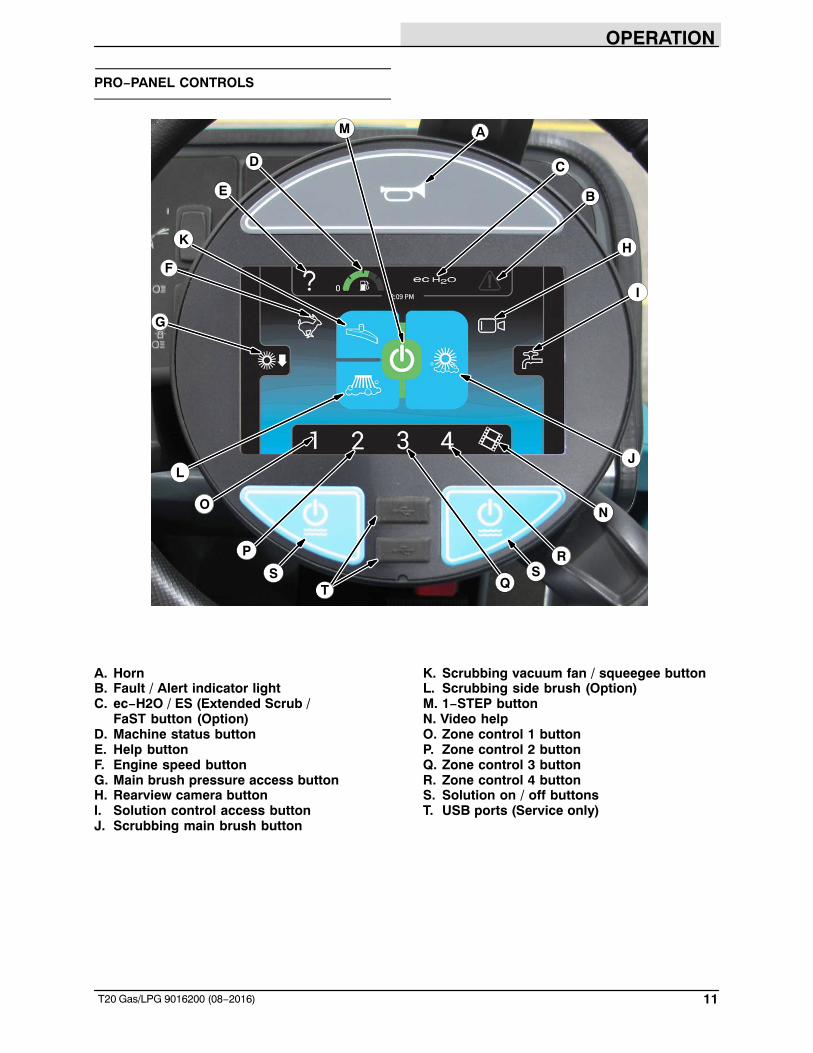
PRO−PANEL CONTROLS
A
B
CD
E
F
G
H
I
J
K
L
M
NO
P
Q
RS S
T
A. HornB. Fault / Alert indicator lightC. ec−H2O / ES (Extended Scrub /
FaST button (Option)D. Machine status buttonE. Help buttonF. Engine speed buttonG. Main brush pressure access buttonH. Rearview camera buttonI. Solution control access buttonJ. Scrubbing main brush button
K. Scrubbing vacuum fan / squeegee buttonL. Scrubbing side brush (Option)M. 1−STEP buttonN. Video helpO. Zone control 1 buttonP. Zone control 2 buttonQ. Zone control 3 buttonR. Zone control 4 buttonS. Solution on / off buttonsT. USB ports (Service only)
OPERATION
12 T20 Gas/LPG 9016200 (08−2016)
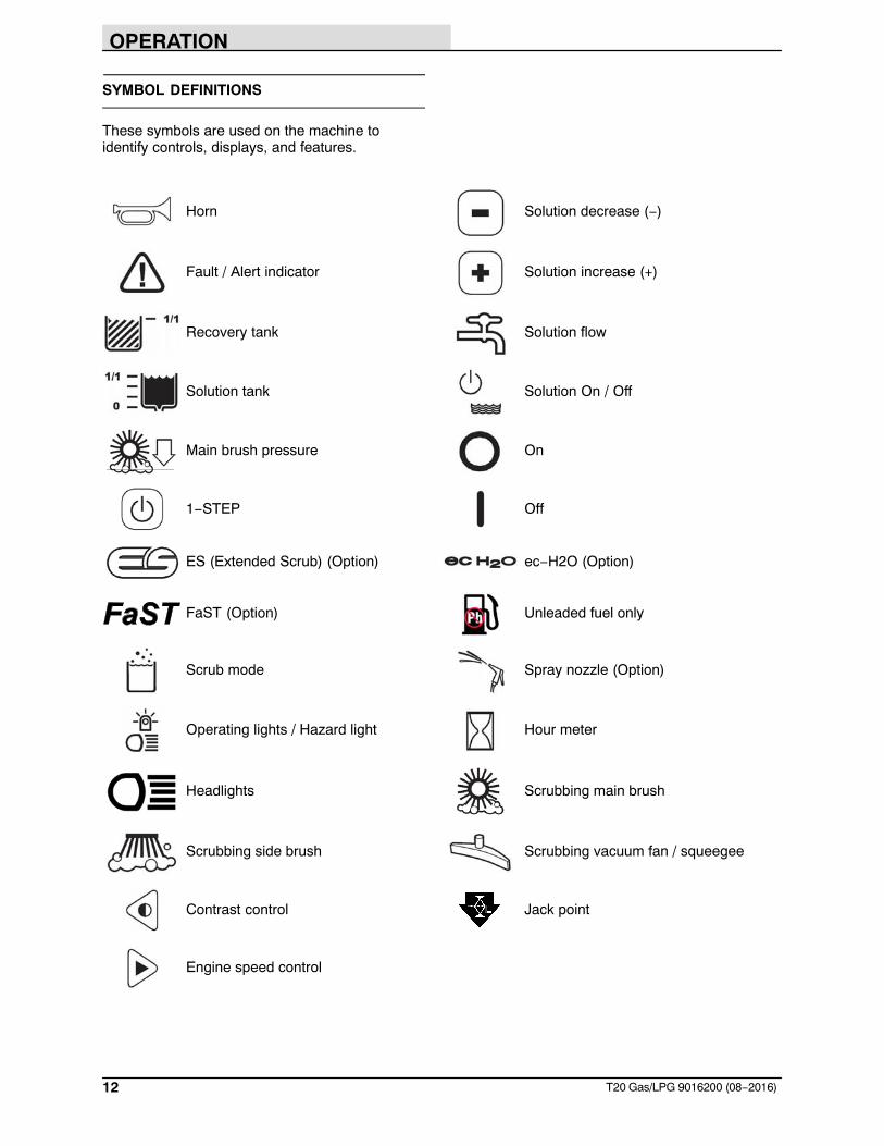
SYMBOL DEFINITIONS
These symbols are used on the machine toidentify controls, displays, and features.
Horn Solution decrease (−)
Fault / Alert indicator Solution increase (+)
Recovery tank Solution flow
Solution tank Solution On / Off
Main brush pressure On
1−STEP Off
ES (Extended Scrub) (Option) ec−H2O (Option)
FaST (Option) Unleaded fuel only
Scrub mode Spray nozzle (Option)
Operating lights / Hazard light Hour meter
Headlights Scrubbing main brush
Scrubbing side brush Scrubbing vacuum fan / squeegee
Contrast control Jack point
Engine speed control
OPERATION
13T20 Gas/LPG 9016200 (08−2016)
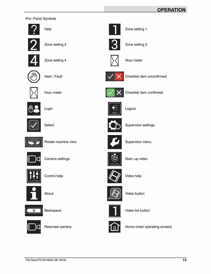
Pro−Panel Symbols
Help Zone setting 1
Zone setting 2 Zone setting 3
Zone setting 4 Hour meter
Alert / Fault Checklist item unconfirmed
Hour meter Checklist item confirmed
Login Logout
Select Supervisor settings
Rotate machine view Supervisor menu
Camera settings Start−up video
Control help Video help
About Video button
Backspace Video list button
Rearview camera Home (main operating screen)
OPERATION
14 T20 Gas/LPG 9016200 (08−2016)
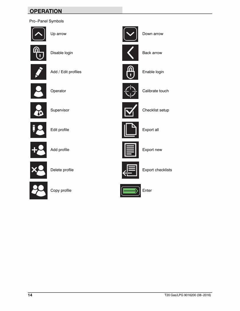
Pro−Panel Symbols
Up arrow Down arrow
Disable login Back arrow
Add / Edit profiles Enable login
Operator Calibrate touch
Supervisor Checklist setup
Edit profile Export all
Add profile Export new
Delete profile Export checklists
Copy profile Enter
OPERATION
15T20 Gas/LPG 9016200 (08−2016)
OPERATION OF CONTROLS − STANDARDPANEL
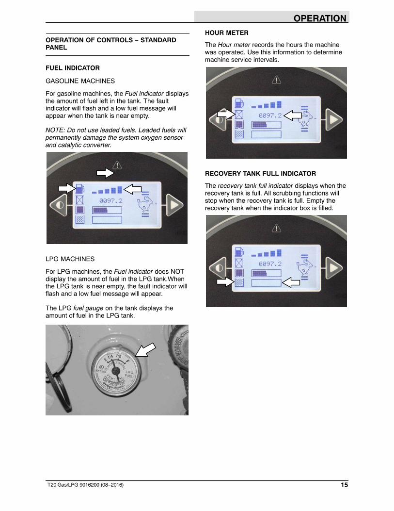
FUEL INDICATOR
GASOLINE MACHINES
For gasoline machines, the Fuel indicator displaysthe amount of fuel left in the tank. The faultindicator will flash and a low fuel message willappear when the tank is near empty.
NOTE: Do not use leaded fuels. Leaded fuels willpermanently damage the system oxygen sensorand catalytic converter.
LPG MACHINES
For LPG machines, the Fuel indicator does NOTdisplay the amount of fuel in the LPG tank.Whenthe LPG tank is near empty, the fault indicator willflash and a low fuel message will appear.
The LPG fuel gauge on the tank displays theamount of fuel in the LPG tank.
HOUR METER
The Hour meter records the hours the machinewas operated. Use this information to determinemachine service intervals.
RECOVERY TANK FULL INDICATOR
The recovery tank full indicator displays when therecovery tank is full. All scrubbing functions willstop when the recovery tank is full. Empty therecovery tank when the indicator box is filled.
OPERATION
16 T20 Gas/LPG 9016200 (08−2016)
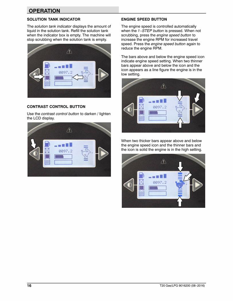
SOLUTION TANK INDICATOR
The solution tank indicator displays the amount ofliquid in the solution tank. Refill the solution tankwhen the indicator box is empty. The machine willstop scrubbing when the solution tank is empty.
CONTRAST CONTROL BUTTON
Use the contrast control button to darken / lightenthe LCD display.
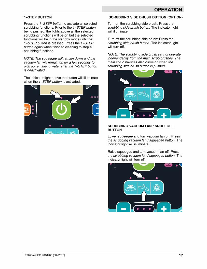
ENGINE SPEED BUTTON
The engine speed is controlled automaticallywhen the 1−STEP button is pressed. When notscrubbing, press the engine speed button toincrease the engine RPM for increased travelspeed. Press the engine speed button again toreduce the engine RPM.
The bars above and below the engine speed iconindicate engine speed setting. When two thinnerbars appear above and below the icon and theicon appears as a line figure the engine is in thelow setting.
When two thicker bars appear above and belowthe engine speed icon and the thinner bars andthe icon is solid the engine is in the high setting.
OPERATION
17T20 Gas/LPG 9016200 (08−2016)
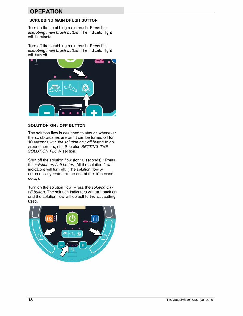
1−STEP BUTTON
Press the 1−STEP button to activate all selectedscrubbing functions. Prior to the 1−STEP buttonbeing pushed, the lights above all the selectedscrubbing functions will be on but the selectedfunctions will be in the standby mode until the1−STEP button is pressed. Press the 1−STEPbutton again when finished cleaning to stop allscrubbing functions.
NOTE: The squeegee will remain down and thevacuum fan will remain on for a few seconds topick up remaining water after the 1−STEP buttonis deactivated.
The indicator light above the button will illuminatewhen the 1−STEP button is activated.
SCRUBBING SIDE BRUSH BUTTON (OPTION)
Turn on the scrubbing side brush: Press thescrubbing side brush button. The indicator lightwill illuminate.
Turn off the scrubbing side brush: Press thescrubbing side brush button. The indicator lightwill turn off.
NOTE: The scrubbing side brush cannot operateindependently from the main scrub brushes. Themain scrub brushes also come on when thescrubbing side brush button is pushed.
SCRUBBING VACUUM FAN / SQUEEGEEBUTTON
Lower squeegee and turn vacuum fan on: Pressthe scrubbing vacuum fan / squeegee button. Theindicator light will illuminate.
Raise squeegee and turn vacuum fan off: Pressthe scrubbing vacuum fan / squeegee button. Theindicator light will turn off.
OPERATION
18 T20 Gas/LPG 9016200 (08−2016)
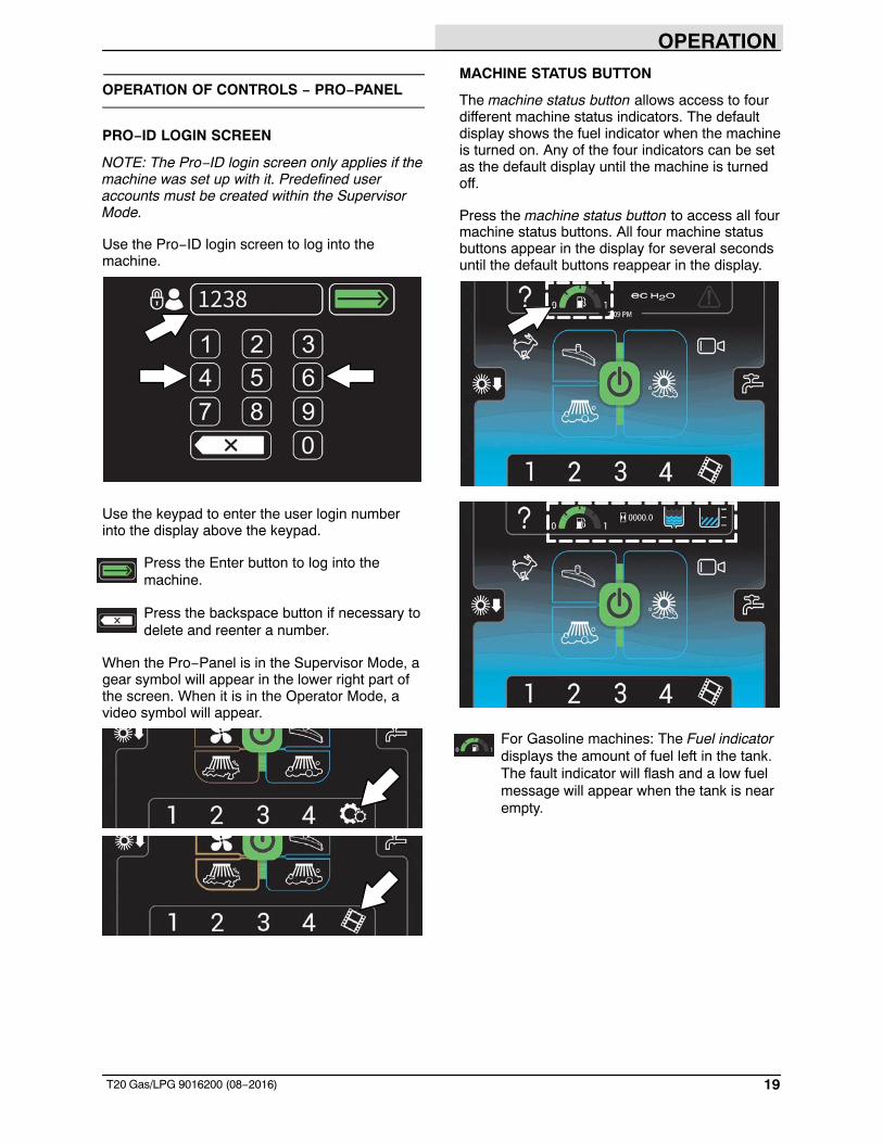
SCRUBBING MAIN BRUSH BUTTON
Turn on the scrubbing main brush: Press thescrubbing main brush button. The indicator lightwill illuminate.
Turn off the scrubbing main brush: Press thescrubbing main brush button. The indicator lightwill turn off.
SOLUTION ON / OFF BUTTON
The solution flow is designed to stay on wheneverthe scrub brushes are on. It can be turned off for10 seconds with the solution on / off button to goaround corners, etc. See also SETTING THESOLUTION FLOW section.
Shut off the solution flow (for 10 seconds) : Pressthe solution on / off button. All the solution flowindicators will turn off. (The solution flow willautomatically restart at the end of the 10 seconddelay).
Turn on the solution flow: Press the solution on /off button. The solution indicators will turn back onand the solution flow will default to the last settingused.
OPERATION
19T20 Gas/LPG 9016200 (08−2016)
OPERATION OF CONTROLS − PRO−PANEL
PRO−ID LOGIN SCREEN
NOTE: The Pro−ID login screen only applies if themachine was set up with it. Predefined useraccounts must be created within the SupervisorMode.
Use the Pro−ID login screen to log into themachine.
Use the keypad to enter the user login numberinto the display above the keypad.
Press the Enter button to log into themachine.
Press the backspace button if necessary todelete and reenter a number.
When the Pro−Panel is in the Supervisor Mode, agear symbol will appear in the lower right part ofthe screen. When it is in the Operator Mode, avideo symbol will appear.
MACHINE STATUS BUTTON
The machine status button allows access to fourdifferent machine status indicators. The defaultdisplay shows the fuel indicator when the machineis turned on. Any of the four indicators can be setas the default display until the machine is turnedoff.
Press the machine status button to access all fourmachine status buttons. All four machine statusbuttons appear in the display for several secondsuntil the default buttons reappear in the display.
For Gasoline machines: The Fuel indicatordisplays the amount of fuel left in the tank.The fault indicator will flash and a low fuelmessage will appear when the tank is nearempty.
OPERATION
20 T20 Gas/LPG 9016200 (08−2016)
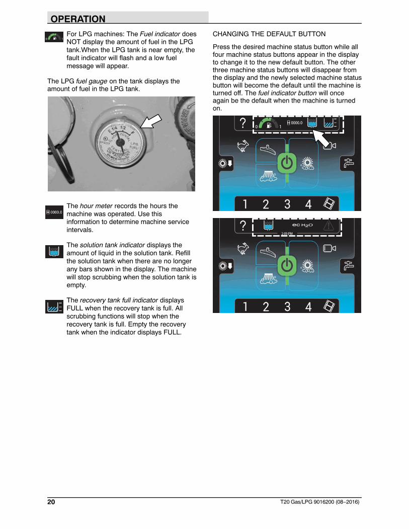
For LPG machines: The Fuel indicator doesNOT display the amount of fuel in the LPGtank.When the LPG tank is near empty, thefault indicator will flash and a low fuelmessage will appear.
The LPG fuel gauge on the tank displays theamount of fuel in the LPG tank.
The hour meter records the hours themachine was operated. Use thisinformation to determine machine serviceintervals.
The solution tank indicator displays theamount of liquid in the solution tank. Refillthe solution tank when there are no longerany bars shown in the display. The machinewill stop scrubbing when the solution tank isempty.
The recovery tank full indicator displaysFULL when the recovery tank is full. Allscrubbing functions will stop when therecovery tank is full. Empty the recoverytank when the indicator displays FULL.
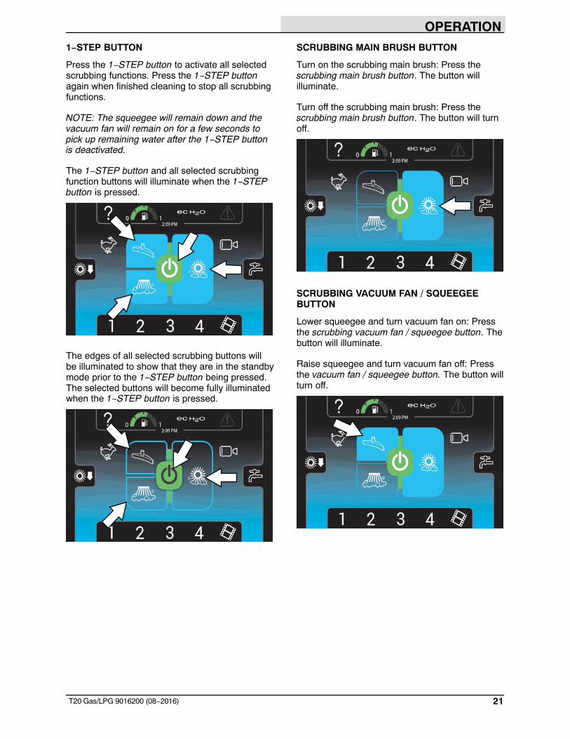
CHANGING THE DEFAULT BUTTON
Press the desired machine status button while allfour machine status buttons appear in the displayto change it to the new default button. The otherthree machine status buttons will disappear fromthe display and the newly selected machine statusbutton will become the default until the machine isturned off. The fuel indicator button will onceagain be the default when the machine is turnedon.
OPERATION
21T20 Gas/LPG 9016200 (08−2016)
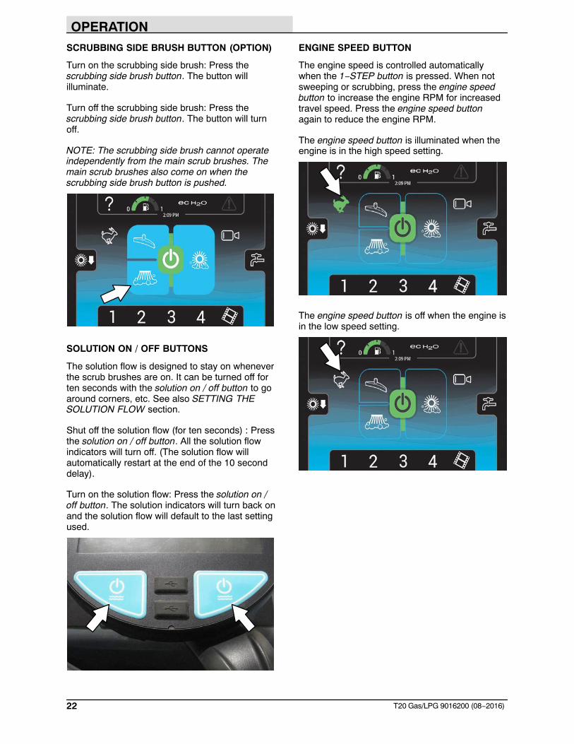
1−STEP BUTTON
Press the 1−STEP button to activate all selectedscrubbing functions. Press the 1−STEP buttonagain when finished cleaning to stop all scrubbingfunctions.
NOTE: The squeegee will remain down and thevacuum fan will remain on for a few seconds topick up remaining water after the 1−STEP buttonis deactivated.
The 1−STEP button and all selected scrubbingfunction buttons will illuminate when the 1−STEPbutton is pressed.
The edges of all selected scrubbing buttons willbe illuminated to show that they are in the standbymode prior to the 1−STEP button being pressed.The selected buttons will become fully illuminatedwhen the 1−STEP button is pressed.
SCRUBBING MAIN BRUSH BUTTON
Turn on the scrubbing main brush: Press thescrubbing main brush button. The button willilluminate.
Turn off the scrubbing main brush: Press thescrubbing main brush button. The button will turnoff.
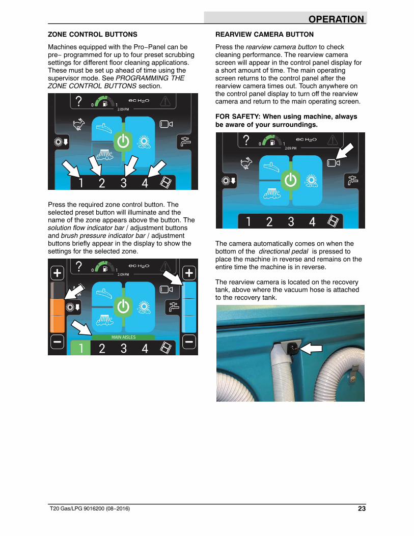
SCRUBBING VACUUM FAN / SQUEEGEEBUTTON
Lower squeegee and turn vacuum fan on: Pressthe scrubbing vacuum fan / squeegee button. Thebutton will illuminate.
Raise squeegee and turn vacuum fan off: Pressthe vacuum fan / squeegee button. The button willturn off.
OPERATION
22 T20 Gas/LPG 9016200 (08−2016)
SCRUBBING SIDE BRUSH BUTTON (OPTION)
Turn on the scrubbing side brush: Press thescrubbing side brush button. The button willilluminate.
Turn off the scrubbing side brush: Press thescrubbing side brush button. The button will turnoff.
NOTE: The scrubbing side brush cannot operateindependently from the main scrub brushes. Themain scrub brushes also come on when thescrubbing side brush button is pushed.
SOLUTION ON / OFF BUTTONS
The solution flow is designed to stay on wheneverthe scrub brushes are on. It can be turned off forten seconds with the solution on / off button to goaround corners, etc. See also SETTING THESOLUTION FLOW section.
Shut off the solution flow (for ten seconds) : Pressthe solution on / off button. All the solution flowindicators will turn off. (The solution flow willautomatically restart at the end of the 10 seconddelay).
Turn on the solution flow: Press the solution on /off button. The solution indicators will turn back onand the solution flow will default to the last settingused.
ENGINE SPEED BUTTON
The engine speed is controlled automaticallywhen the 1−STEP button is pressed. When notsweeping or scrubbing, press the engine speedbutton to increase the engine RPM for increasedtravel speed. Press the engine speed buttonagain to reduce the engine RPM.
The engine speed button is illuminated when theengine is in the high speed setting.
The engine speed button is off when the engine isin the low speed setting.
OPERATION
23T20 Gas/LPG 9016200 (08−2016)
ZONE CONTROL BUTTONS
Machines equipped with the Pro−Panel can bepre− programmed for up to four preset scrubbingsettings for different floor cleaning applications.These must be set up ahead of time using thesupervisor mode. See PROGRAMMING THEZONE CONTROL BUTTONS section.
Press the required zone control button. Theselected preset button will illuminate and thename of the zone appears above the button. Thesolution flow indicator bar / adjustment buttonsand brush pressure indicator bar / adjustmentbuttons briefly appear in the display to show thesettings for the selected zone.
REARVIEW CAMERA BUTTON
Press the rearview camera button to checkcleaning performance. The rearview camerascreen will appear in the control panel display fora short amount of time. The main operatingscreen returns to the control panel after therearview camera times out. Touch anywhere onthe control panel display to turn off the rearviewcamera and return to the main operating screen.
FOR SAFETY: When using machine, alwaysbe aware of your surroundings.
The camera automatically comes on when thebottom of the directional pedal is pressed toplace the machine in reverse and remains on theentire time the machine is in reverse.
The rearview camera is located on the recoverytank, above where the vacuum hose is attachedto the recovery tank.
OPERATION
24 T20 Gas/LPG 9016200 (08−2016)
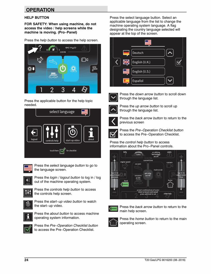
HELP BUTTON
FOR SAFETY: When using machine, do notaccess the video / help screens while themachine is moving. (Pro−Panel)
Press the help button to access the help screen.
Press the applicable button for the help topicneeded.
Press the select language button to go tothe language screen.
Press the login / logout button to log in / logout of the machine operating system.
Press the controls help button to accessthe controls help screen.
Press the start−up video button to watchthe start−up video.
Press the about button to access machineoperating system information.
Press the Pre−Operation Checklist buttonto access the Pre−Operation Checklist.
Press the select language button. Select anapplicable language from the list to change themachine operating system language. A flagdesignating the country language selected willappear at the top of the screen.
Press the down arrow button to scroll downthrough the language list.
Press the up arrow button to scroll upthrough the language list.
Press the back arrow button to return to theprevious screen
Press the Pre−Operation Checklist buttonto access the Pre−Operation Checklist.
Press the control help button to accessinformation about the Pro−Panel controls.
Press the back arrow button to return to themain help screen.
Press the home button to return to the mainoperating screen.
OPERATION
25T20 Gas/LPG 9016200 (08−2016)
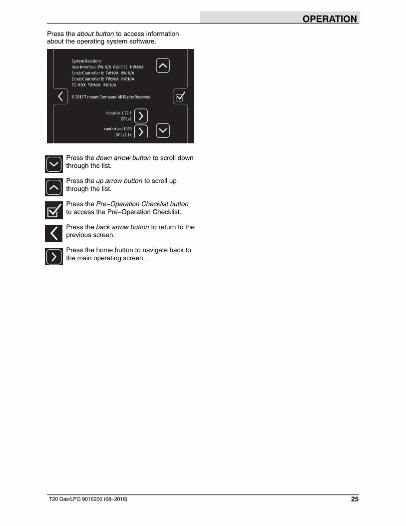
Press the about button to access informationabout the operating system software.
Press the down arrow button to scroll downthrough the list.
Press the up arrow button to scroll upthrough the list.
Press the Pre−Operation Checklist buttonto access the Pre−Operation Checklist.
Press the back arrow button to return to theprevious screen.
Press the home button to navigate back tothe main operating screen.
OPERATION
26 T20 Gas/LPG 9016200 (08−2016)
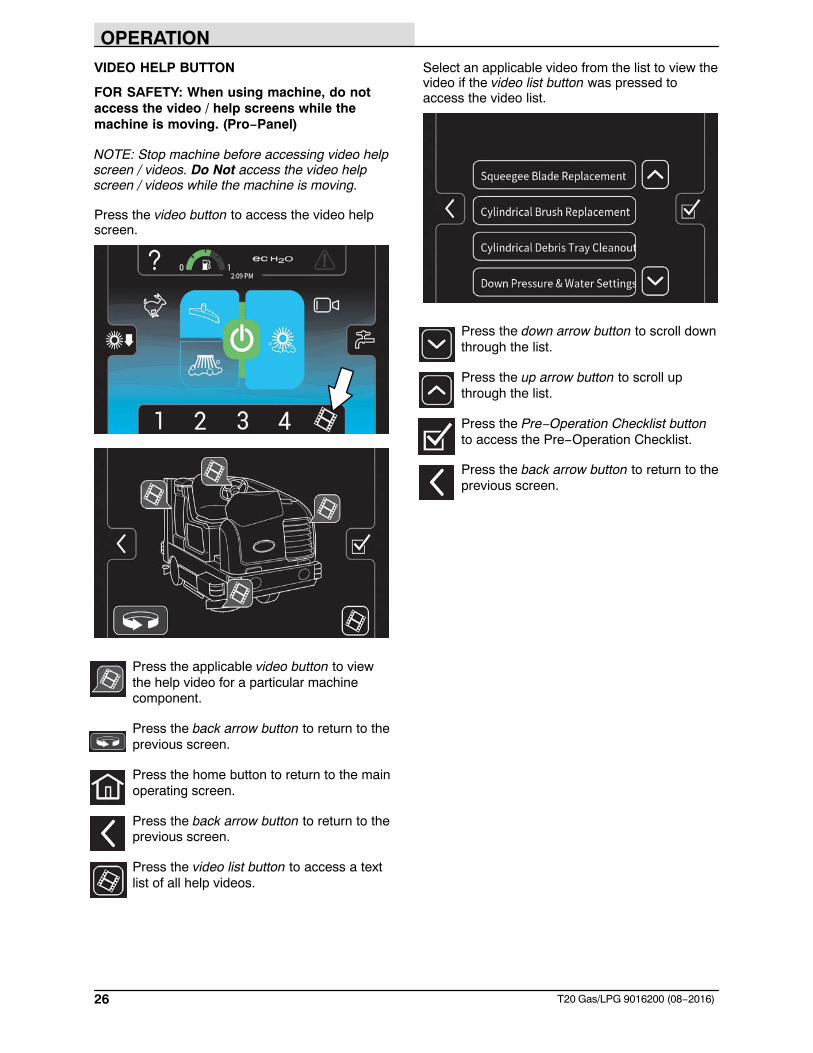
VIDEO HELP BUTTON
FOR SAFETY: When using machine, do notaccess the video / help screens while themachine is moving. (Pro−Panel)
NOTE: Stop machine before accessing video helpscreen / videos. Do Not access the video helpscreen / videos while the machine is moving.
Press the video button to access the video helpscreen.
Press the applicable video button to viewthe help video for a particular machinecomponent.
Press the back arrow button to return to theprevious screen.
Press the home button to return to the mainoperating screen.
Press the back arrow button to return to theprevious screen.
Press the video list button to access a textlist of all help videos.
Select an applicable video from the list to view thevideo if the video list button was pressed toaccess the video list.
Press the down arrow button to scroll downthrough the list.
Press the up arrow button to scroll upthrough the list.
Press the Pre−Operation Checklist buttonto access the Pre−Operation Checklist.
Press the back arrow button to return to theprevious screen.
OPERATION
27T20 Gas/LPG 9016200 (08−2016)
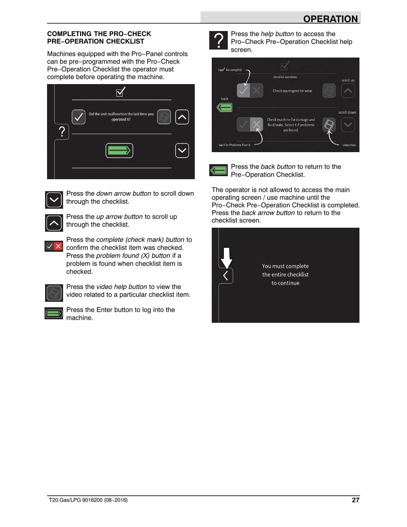
COMPLETING THE PRO−CHECKPRE−OPERATION CHECKLIST
Machines equipped with the Pro−Panel controlscan be pre−programmed with the Pro−CheckPre−Operation Checklist the operator mustcomplete before operating the machine.
Press the down arrow button to scroll downthrough the checklist.
Press the up arrow button to scroll upthrough the checklist.
Press the complete (check mark) button toconfirm the checklist item was checked.Press the problem found (X) button if aproblem is found when checklist item ischecked.
Press the video help button to view thevideo related to a particular checklist item.
Press the Enter button to log into themachine.
Press the help button to access thePro−Check Pre−Operation Checklist helpscreen.
Press the back button to return to thePre−Operation Checklist.
The operator is not allowed to access the mainoperating screen / use machine until thePro−Check Pre−Operation Checklist is completed.Press the back arrow button to return to thechecklist screen.
OPERATION
28 T20 Gas/LPG 9016200 (08−2016)
OPERATION OF CONTROLS − ALLMACHINES
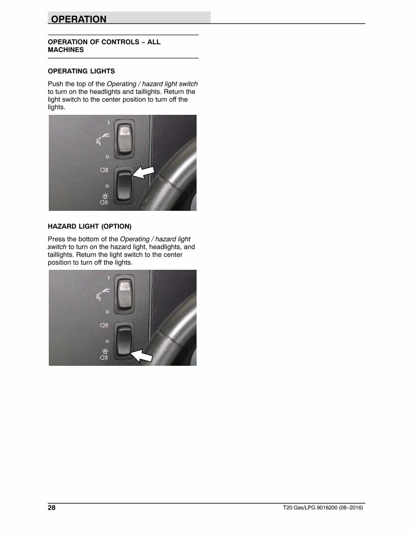
OPERATING LIGHTS
Push the top of the Operating / hazard light switchto turn on the headlights and taillights. Return thelight switch to the center position to turn off thelights.
HAZARD LIGHT (OPTION)
Press the bottom of the Operating / hazard lightswitch to turn on the hazard light, headlights, andtaillights. Return the light switch to the centerposition to turn off the lights.
OPERATION
29T20 Gas/LPG 9016200 (08−2016)
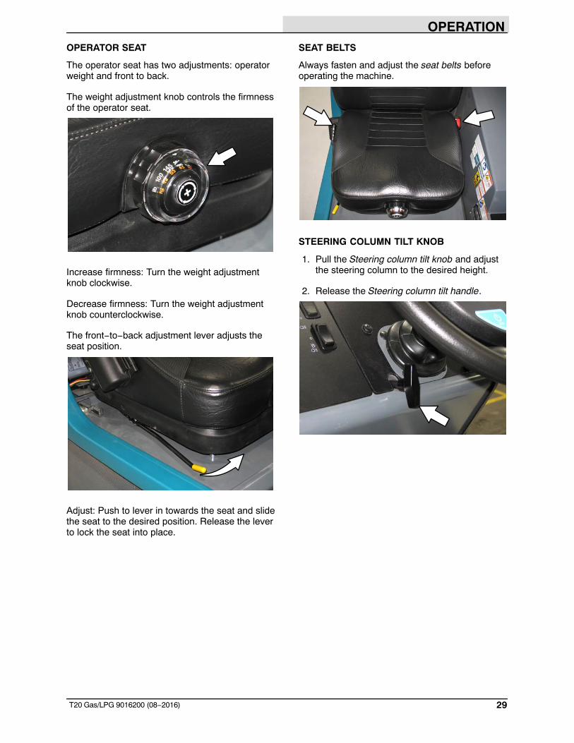
OPERATOR SEAT
The operator seat has two adjustments: operatorweight and front to back.
The weight adjustment knob controls the firmnessof the operator seat.
Increase firmness: Turn the weight adjustmentknob clockwise.
Decrease firmness: Turn the weight adjustmentknob counterclockwise.
The front−to−back adjustment lever adjusts theseat position.
Adjust: Push to lever in towards the seat and slidethe seat to the desired position. Release the leverto lock the seat into place.
SEAT BELTS
Always fasten and adjust the seat belts beforeoperating the machine.
STEERING COLUMN TILT KNOB
1. Pull the Steering column tilt knob and adjustthe steering column to the desired height.
2. Release the Steering column tilt handle.
OPERATION
30 T20 Gas/LPG 9016200 (08−2016)
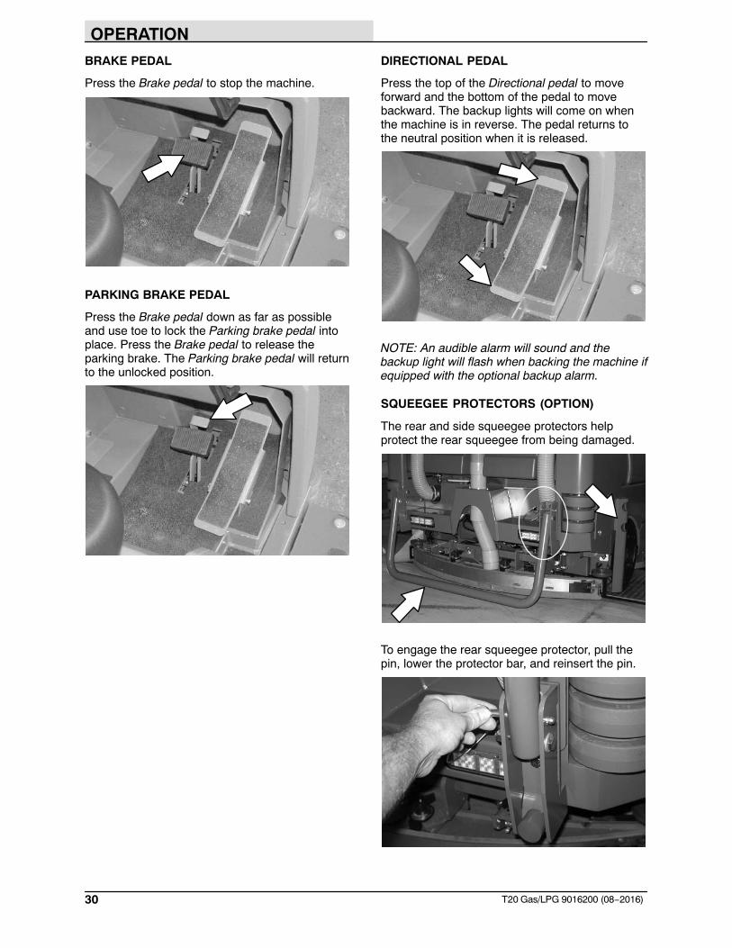
BRAKE PEDAL
Press the Brake pedal to stop the machine.
PARKING BRAKE PEDAL
Press the Brake pedal down as far as possibleand use toe to lock the Parking brake pedal intoplace. Press the Brake pedal to release theparking brake. The Parking brake pedal will returnto the unlocked position.
DIRECTIONAL PEDAL
Press the top of the Directional pedal to moveforward and the bottom of the pedal to movebackward. The backup lights will come on whenthe machine is in reverse. The pedal returns tothe neutral position when it is released.
NOTE: An audible alarm will sound and thebackup light will flash when backing the machine ifequipped with the optional backup alarm.
SQUEEGEE PROTECTORS (OPTION)
The rear and side squeegee protectors helpprotect the rear squeegee from being damaged.
To engage the rear squeegee protector, pull thepin, lower the protector bar, and reinsert the pin.
OPERATION
31T20 Gas/LPG 9016200 (08−2016)
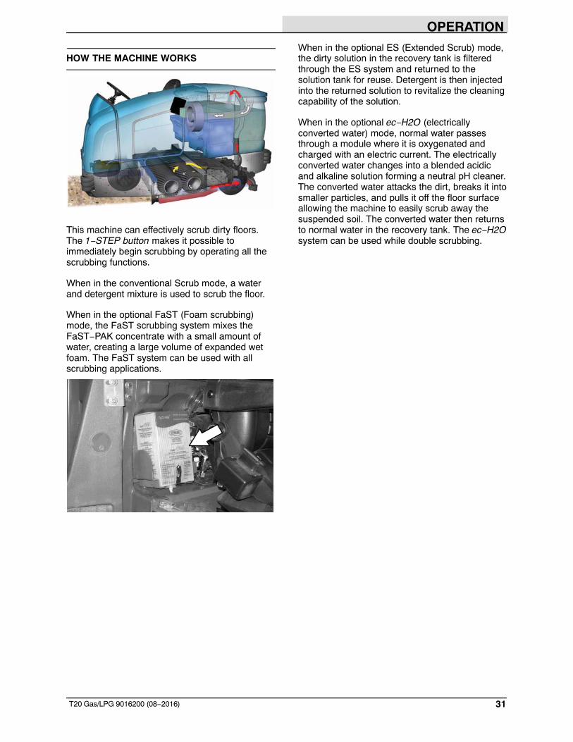
HOW THE MACHINE WORKS
This machine can effectively scrub dirty floors.The 1−STEP button makes it possible toimmediately begin scrubbing by operating all thescrubbing functions.
When in the conventional Scrub mode, a waterand detergent mixture is used to scrub the floor.
When in the optional FaST (Foam scrubbing)mode, the FaST scrubbing system mixes theFaST−PAK concentrate with a small amount ofwater, creating a large volume of expanded wetfoam. The FaST system can be used with allscrubbing applications.
When in the optional ES (Extended Scrub) mode,the dirty solution in the recovery tank is filteredthrough the ES system and returned to thesolution tank for reuse. Detergent is then injectedinto the returned solution to revitalize the cleaningcapability of the solution.
When in the optional ec−H2O (electricallyconverted water) mode, normal water passesthrough a module where it is oxygenated andcharged with an electric current. The electricallyconverted water changes into a blended acidicand alkaline solution forming a neutral pH cleaner.The converted water attacks the dirt, breaks it intosmaller particles, and pulls it off the floor surfaceallowing the machine to easily scrub away thesuspended soil. The converted water then returnsto normal water in the recovery tank. The ec−H2Osystem can be used while double scrubbing.
OPERATION
32 T20 Gas/LPG 9016200 (08−2016)
BRUSH AND PAD INFORMATION
For best results, use the correct brush type for thecleaning application. Listed below are the brushesand the applications for which each is best suited.
NOTE: The amount and type of soilage play animportant role in determining the type of brushesto use. Contact a Tennant representative forspecific recommendations.
Nylon brush (Disk)* − Softer nylon bristles arerecommended for scrubbing coated floors. Cleanswithout scuffing.
Polyester brush (Cylindrical) − Softer generalpurpose polyester bristles gently clean whilescrubbing. Perfect for sensitive floor surfaces.Polyester does not absorb water so it is preferredover Nylon in wet applications.
PolyPro brush (Cylindrical) − Heavy dutypolypropylene bristles provide a more aggressivecleaning performance and can more easily liftcompacted dirt, debris, and sand while offeringexcellent scrubbing performance.
Polypropylene brush (Cylindrical and Disk)* −General purpose polypropylene bristles lift lightlycompacted dirt without scuffing high-gloss coatedfloors.
Super AB brush (Cylindrical and Disk)* −Nylon fiber impregnated with abrasive grit toremove stains and compacted dirt. Aggressiveaction on any surface. Performs well on buildup,grease, or tire marks.
* This brush is also available for the side brush.
Stripping pad − This brown pad is for strippingfloors. Quickly and easily cuts through old finish toprepare the floor for recoating.
Scrubbing pad − This blue pad is for scrubbingfloors. Removes dirt, spills, and scuffs. Leaves aclean surface ready for re-coating.
Buffing pad − This red pad is for buffing floors.Quickly cleans and removes scuff marks whilepolishing the floor to a high gloss.
Polishing pad − This white pad is for polishingfloors. Maintains a high gloss. Use for buffing verysoft finishes and lower traffic areas, and polishingsoft waxes on wood floors.
High productivity pad − This black pad is foraggressively stripping floor finishes/sealers or forvery heavy−duty scrubbing. This pad can only beused with the grip pad driver, not the tufted paddriver.
Surface preparation pad − This maroon pad isfor very aggressive floor stripping withoutchemicals.
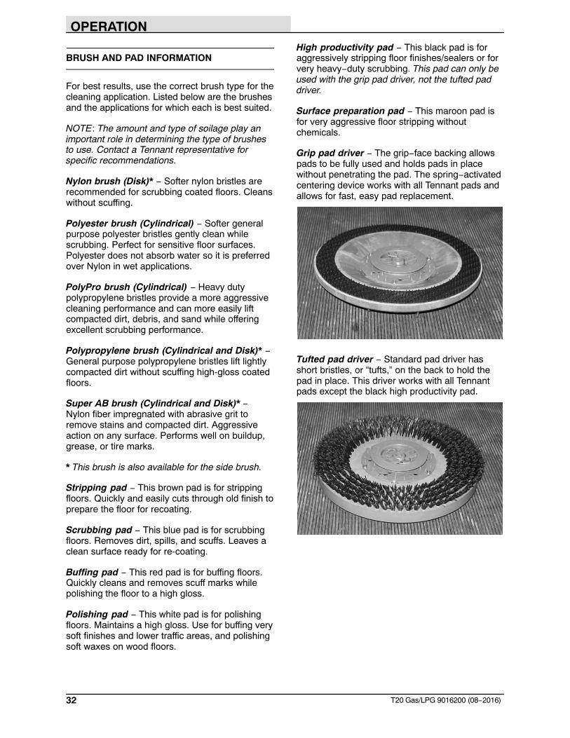
Grip pad driver − The grip−face backing allowspads to be fully used and holds pads in placewithout penetrating the pad. The spring−activatedcentering device works with all Tennant pads andallows for fast, easy pad replacement.
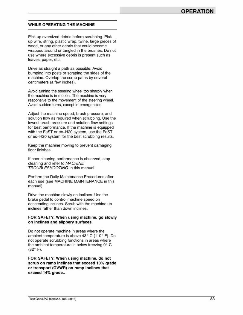
Tufted pad driver − Standard pad driver hasshort bristles, or “tufts,” on the back to hold thepad in place. This driver works with all Tennantpads except the black high productivity pad.
OPERATION
33T20 Gas/LPG 9016200 (08−2016)
WHILE OPERATING THE MACHINE
Pick up oversized debris before scrubbing. Pickup wire, string, plastic wrap, twine, large pieces ofwood, or any other debris that could becomewrapped around or tangled in the brushes. Do notuse where excessive debris is present such asleaves, paper, etc.
Drive as straight a path as possible. Avoidbumping into posts or scraping the sides of themachine. Overlap the scrub paths by severalcentimeters (a few inches).
Avoid turning the steering wheel too sharply whenthe machine is in motion. The machine is veryresponsive to the movement of the steering wheel.Avoid sudden turns, except in emergencies.
Adjust the machine speed, brush pressure, andsolution flow as required when scrubbing. Use thelowest brush pressure and solution flow settingsfor best performance. If the machine is equippedwith the FaST or ec−H20 system, use the FaSTor ec−H20 system for the best scrubbing results.
Keep the machine moving to prevent damagingfloor finishes.
If poor cleaning performance is observed, stopcleaning and refer to MACHINETROUBLESHOOTING in this manual.
Perform the Daily Maintenance Procedures aftereach use (see MACHINE MAINTENANCE in thismanual).
Drive the machine slowly on inclines. Use thebrake pedal to control machine speed ondescending inclines. Scrub with the machine upinclines rather than down inclines.
FOR SAFETY: When using machine, go slowlyon inclines and slippery surfaces.
Do not operate machine in areas where theambient temperature is above 43� C (110� F). Donot operate scrubbing functions in areas wherethe ambient temperature is below freezing 0� C(32� F).
FOR SAFETY: When using machine, do notscrub on ramp inclines that exceed 10% gradeor transport (GVWR) on ramp inclines thatexceed 14% grade..
OPERATION
34 T20 Gas/LPG 9016200 (08−2016)
PRE−OPERATION CHECKLIST
� Check the hydraulic fluid level.
� Check the fuel level.
� Check the machine for fluid leaks.
� Check the condition of the main brushes.Remove string, banding, plastic wrap, or otherdebris wrapped around the brushes.
� Cylindrical brushes: Check that the debris trayis empty and clean.
� Check the main brush compartment rightskirts, seals, and squeegee for damage andwear.
� Side Brush Option: Check the condition of thebrush. Remove string, banding, plastic wrap,or other debris wrapped around the brush.
� Side Brush Option: Check the condition of theside brush squeegee.
� Check the radiator and hydraulic cooler finsfor debris.
� Check the engine coolant level.
� Check the engine oil level.
� Check the main brush compartment left skirts,seals, and squeegee for damage and wear.
� Check the left solution tank cover seal fordamage and wear.
� Check the recovery tank cover seal fordamage and wear.
� Clean the vacuum fan debris filter.
� Drain and clean the recovery tank.
� ES Option: Drain and clean the solution tank,float sensor, and ES filter.
� Check the right solution tank cover seal fordamage and wear.
� Check the squeegee hose for debris orblockage.
� Check the squeegees for damage, wear, anddeflection adjustment.
� FaST Scrubbing: Check the FaST−PAKconcentrate agent level. Replace carton asneeded. See the INSTALLING THEFaST−PAK CARTON section of the manual.
� FaST Scrubbing: Ensure all conventionalcleaning agents are drained and rinsed fromthe solution tank.
� FaST Scrubbing: Ensure the solution tank isfilled with clear cool water only.
� Check the headlights, taillights, and safetylights.
� Check the brakes and steering for properoperation.
� Check the service records to determinemaintenance requirements.
OPERATION
35T20 Gas/LPG 9016200 (08−2016)
CHANGING THE LPG TANK
FOR SAFETY: Before leaving or servicingmachine, stop on level surface, set parkingbrake, turn off machine, and remove key.
1. Open the side access door.
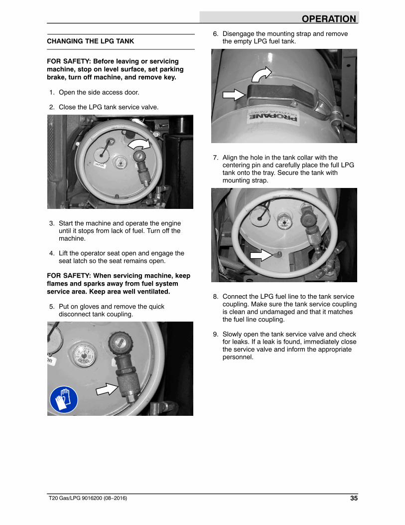
2. Close the LPG tank service valve.
3. Start the machine and operate the engineuntil it stops from lack of fuel. Turn off themachine.
4. Lift the operator seat open and engage theseat latch so the seat remains open.
FOR SAFETY: When servicing machine, keepflames and sparks away from fuel systemservice area. Keep area well ventilated.
5. Put on gloves and remove the quickdisconnect tank coupling.
6. Disengage the mounting strap and removethe empty LPG fuel tank.
7. Align the hole in the tank collar with thecentering pin and carefully place the full LPGtank onto the tray. Secure the tank withmounting strap.
8. Connect the LPG fuel line to the tank servicecoupling. Make sure the tank service couplingis clean and undamaged and that it matchesthe fuel line coupling.
9. Slowly open the tank service valve and checkfor leaks. If a leak is found, immediately closethe service valve and inform the appropriatepersonnel.
OPERATION
36 T20 Gas/LPG 9016200 (08−2016)
STARTING THE MACHINE
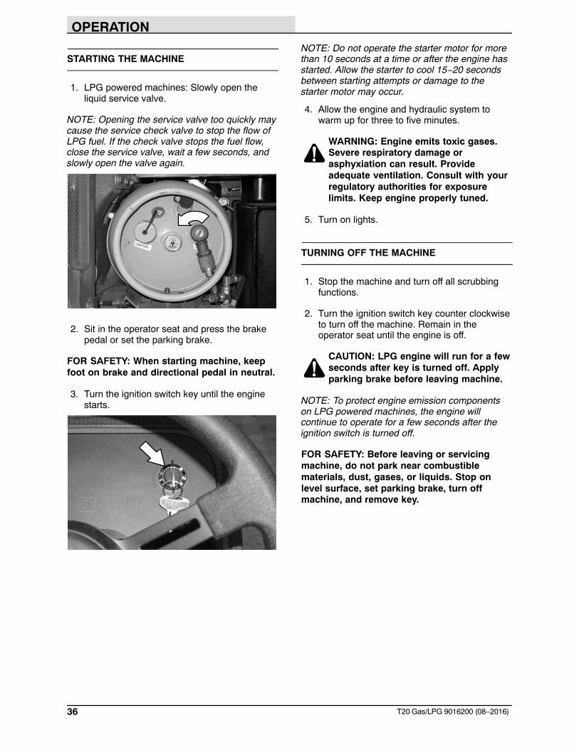
1. LPG powered machines: Slowly open theliquid service valve.
NOTE: Opening the service valve too quickly maycause the service check valve to stop the flow ofLPG fuel. If the check valve stops the fuel flow,close the service valve, wait a few seconds, andslowly open the valve again.
2. Sit in the operator seat and press the brakepedal or set the parking brake.
FOR SAFETY: When starting machine, keepfoot on brake and directional pedal in neutral.
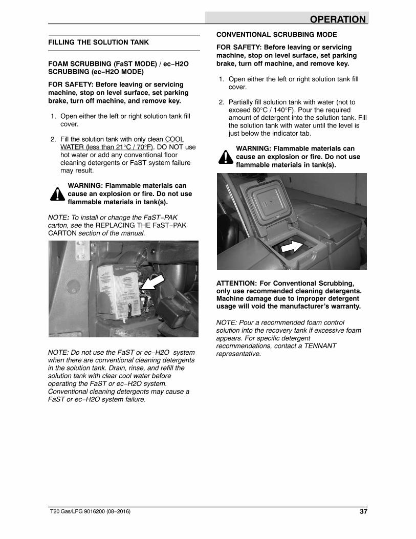
3. Turn the ignition switch key until the enginestarts.
NOTE: Do not operate the starter motor for morethan 10 seconds at a time or after the engine hasstarted. Allow the starter to cool 15−20 secondsbetween starting attempts or damage to thestarter motor may occur.
4. Allow the engine and hydraulic system towarm up for three to five minutes.
WARNING: Engine emits toxic gases.Severe respiratory damage orasphyxiation can result. Provideadequate ventilation. Consult with yourregulatory authorities for exposurelimits. Keep engine properly tuned.
5. Turn on lights.
TURNING OFF THE MACHINE
1. Stop the machine and turn off all scrubbingfunctions.
2. Turn the ignition switch key counter clockwiseto turn off the machine. Remain in theoperator seat until the engine is off.
CAUTION: LPG engine will run for a fewseconds after key is turned off. Applyparking brake before leaving machine.
NOTE: To protect engine emission componentson LPG powered machines, the engine willcontinue to operate for a few seconds after theignition switch is turned off.
FOR SAFETY: Before leaving or servicingmachine, do not park near combustiblematerials, dust, gases, or liquids. Stop onlevel surface, set parking brake, turn offmachine, and remove key.
OPERATION
37T20 Gas/LPG 9016200 (08−2016)
FILLING THE SOLUTION TANK
FOAM SCRUBBING (FaST MODE) / ec−H2OSCRUBBING (ec−H2O MODE)
FOR SAFETY: Before leaving or servicingmachine, stop on level surface, set parkingbrake, turn off machine, and remove key.
1. Open either the left or right solution tank fillcover.
2. Fill the solution tank with only clean COOLWATER (less than 21°C / 70°F). DO NOT usehot water or add any conventional floorcleaning detergents or FaST system failuremay result.
WARNING: Flammable materials cancause an explosion or fire. Do not useflammable materials in tank(s).
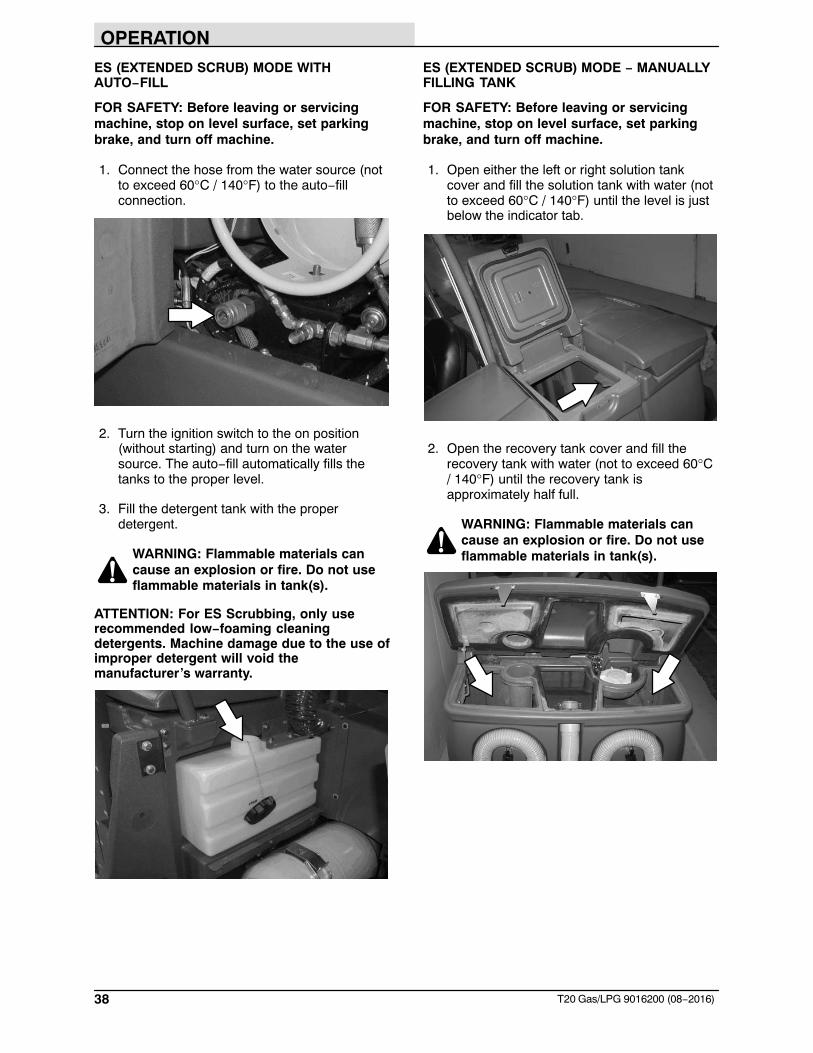
NOTE: To install or change the FaST−PAKcarton, see the REPLACING THE FaST−PAKCARTON section of the manual.
NOTE: Do not use the FaST or ec−H2O systemwhen there are conventional cleaning detergentsin the solution tank. Drain, rinse, and refill thesolution tank with clear cool water beforeoperating the FaST or ec−H2O system.Conventional cleaning detergents may cause aFaST or ec−H2O system failure.
CONVENTIONAL SCRUBBING MODE
FOR SAFETY: Before leaving or servicingmachine, stop on level surface, set parkingbrake, turn off machine, and remove key.
1. Open either the left or right solution tank fillcover.
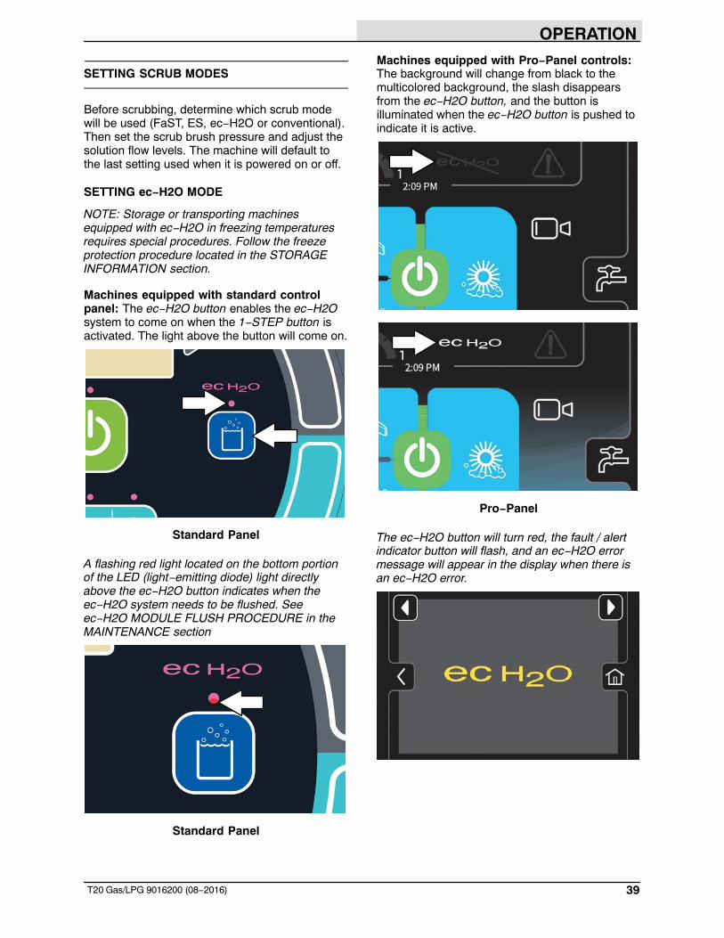
2. Partially fill solution tank with water (not toexceed 60°C / 140°F). Pour the requiredamount of detergent into the solution tank. Fillthe solution tank with water until the level isjust below the indicator tab.
WARNING: Flammable materials cancause an explosion or fire. Do not useflammable materials in tank(s).
ATTENTION: For Conventional Scrubbing,only use recommended cleaning detergents.Machine damage due to improper detergentusage will void the manufacturer’s warranty.
NOTE: Pour a recommended foam controlsolution into the recovery tank if excessive foamappears. For specific detergentrecommendations, contact a TENNANTrepresentative.
OPERATION
38 T20 Gas/LPG 9016200 (08−2016)
ES (EXTENDED SCRUB) MODE WITHAUTO−FILL
FOR SAFETY: Before leaving or servicingmachine, stop on level surface, set parkingbrake, and turn off machine.
1. Connect the hose from the water source (notto exceed 60°C / 140°F) to the auto−fillconnection.
2. Turn the ignition switch to the on position(without starting) and turn on the watersource. The auto−fill automatically fills thetanks to the proper level.
3. Fill the detergent tank with the properdetergent.
WARNING: Flammable materials cancause an explosion or fire. Do not useflammable materials in tank(s).
ATTENTION: For ES Scrubbing, only userecommended low−foaming cleaningdetergents. Machine damage due to the use ofimproper detergent will void themanufacturer’s warranty.
ES (EXTENDED SCRUB) MODE − MANUALLYFILLING TANK
FOR SAFETY: Before leaving or servicingmachine, stop on level surface, set parkingbrake, and turn off machine.
1. Open either the left or right solution tankcover and fill the solution tank with water (notto exceed 60°C / 140°F) until the level is justbelow the indicator tab.
2. Open the recovery tank cover and fill therecovery tank with water (not to exceed 60°C/ 140°F) until the recovery tank isapproximately half full.
WARNING: Flammable materials cancause an explosion or fire. Do not useflammable materials in tank(s).
OPERATION
39T20 Gas/LPG 9016200 (08−2016)
SETTING SCRUB MODES
Before scrubbing, determine which scrub modewill be used (FaST, ES, ec−H2O or conventional).Then set the scrub brush pressure and adjust thesolution flow levels. The machine will default tothe last setting used when it is powered on or off.
SETTING ec−H2O MODE
NOTE: Storage or transporting machinesequipped with ec−H2O in freezing temperaturesrequires special procedures. Follow the freezeprotection procedure located in the STORAGEINFORMATION section.
Machines equipped with standard controlpanel: The ec−H2O button enables the ec−H2Osystem to come on when the 1−STEP button isactivated. The light above the button will come on.
Standard Panel
A flashing red light located on the bottom portionof the LED (light−emitting diode) light directlyabove the ec−H2O button indicates when theec−H2O system needs to be flushed. Seeec−H2O MODULE FLUSH PROCEDURE in theMAINTENANCE section
Standard Panel
Machines equipped with Pro−Panel controls:The background will change from black to themulticolored background, the slash disappearsfrom the ec−H2O button, and the button isilluminated when the ec−H2O button is pushed toindicate it is active.
Pro−Panel
The ec−H2O button will turn red, the fault / alertindicator button will flash, and an ec−H2O errormessage will appear in the display when there isan ec−H2O error.
OPERATION
40 T20 Gas/LPG 9016200 (08−2016)
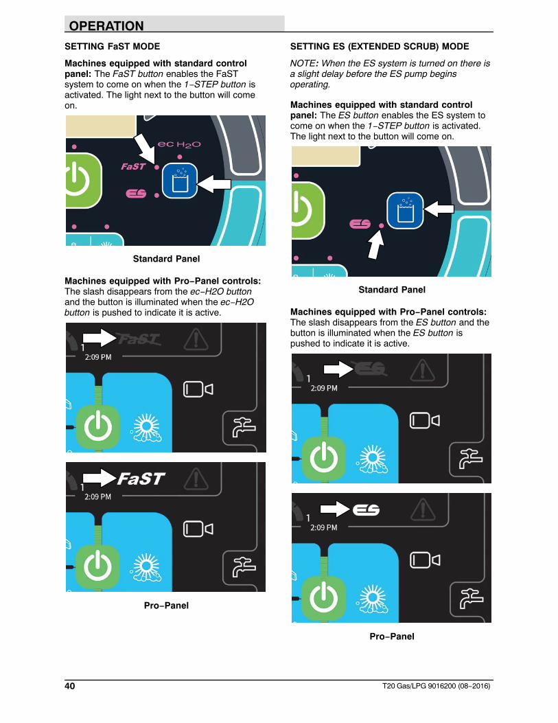
SETTING FaST MODE
Machines equipped with standard controlpanel: The FaST button enables the FaSTsystem to come on when the 1−STEP button isactivated. The light next to the button will comeon.
Standard Panel
Machines equipped with Pro−Panel controls:The slash disappears from the ec−H2O buttonand the button is illuminated when the ec−H2Obutton is pushed to indicate it is active.
Pro−Panel
SETTING ES (EXTENDED SCRUB) MODE
NOTE: When the ES system is turned on there isa slight delay before the ES pump beginsoperating.
Machines equipped with standard controlpanel: The ES button enables the ES system tocome on when the 1−STEP button is activated.The light next to the button will come on.
Standard Panel
Machines equipped with Pro−Panel controls:The slash disappears from the ES button and thebutton is illuminated when the ES button ispushed to indicate it is active.
Pro−Panel
OPERATION
41T20 Gas/LPG 9016200 (08−2016)
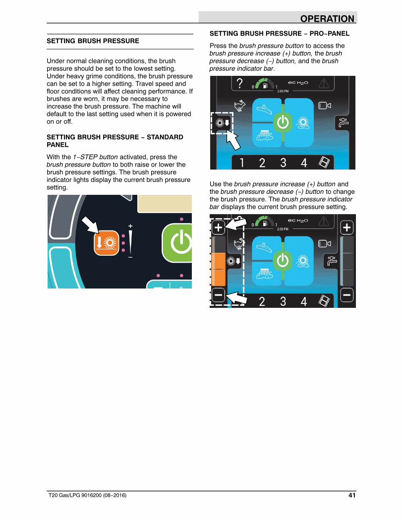
SETTING BRUSH PRESSURE
Under normal cleaning conditions, the brushpressure should be set to the lowest setting.Under heavy grime conditions, the brush pressurecan be set to a higher setting. Travel speed andfloor conditions will affect cleaning performance. Ifbrushes are worn, it may be necessary toincrease the brush pressure. The machine willdefault to the last setting used when it is poweredon or off.
SETTING BRUSH PRESSURE − STANDARDPANEL
With the 1−STEP button activated, press thebrush pressure button to both raise or lower thebrush pressure settings. The brush pressureindicator lights display the current brush pressuresetting.
SETTING BRUSH PRESSURE − PRO−PANEL
Press the brush pressure button to access thebrush pressure increase (+) button, the brushpressure decrease (−) button, and the brushpressure indicator bar.
Use the brush pressure increase (+) button andthe brush pressure decrease (−) button to changethe brush pressure. The brush pressure indicatorbar displays the current brush pressure setting.
OPERATION
42 T20 Gas/LPG 9016200 (08−2016)
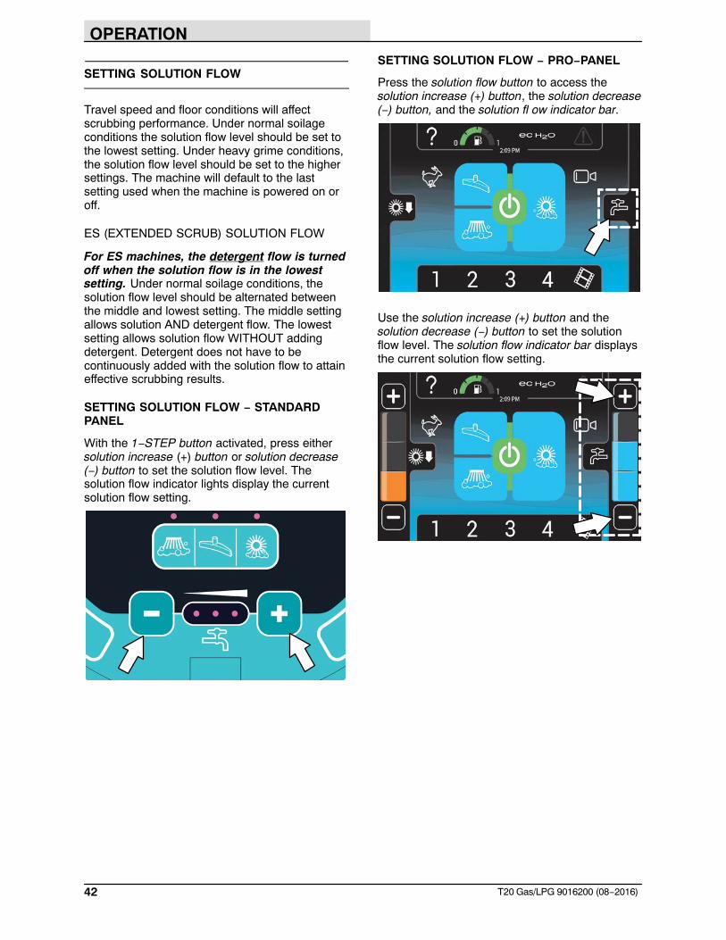
SETTING SOLUTION FLOW
Travel speed and floor conditions will affectscrubbing performance. Under normal soilageconditions the solution flow level should be set tothe lowest setting. Under heavy grime conditions,the solution flow level should be set to the highersettings. The machine will default to the lastsetting used when the machine is powered on oroff.
ES (EXTENDED SCRUB) SOLUTION FLOW
For ES machines, the detergent flow is turnedoff when the solution flow is in the lowestsetting. Under normal soilage conditions, thesolution flow level should be alternated betweenthe middle and lowest setting. The middle settingallows solution AND detergent flow. The lowestsetting allows solution flow WITHOUT addingdetergent. Detergent does not have to becontinuously added with the solution flow to attaineffective scrubbing results.
SETTING SOLUTION FLOW − STANDARDPANEL
With the 1−STEP button activated, press eithersolution increase (+) button or solution decrease(−) button to set the solution flow level. Thesolution flow indicator lights display the currentsolution flow setting.
SETTING SOLUTION FLOW − PRO−PANEL
Press the solution flow button to access thesolution increase (+) button, the solution decrease(−) button, and the solution fl ow indicator bar.
Use the solution increase (+) button and thesolution decrease (−) button to set the solutionflow level. The solution flow indicator bar displaysthe current solution flow setting.
OPERATION
43T20 Gas/LPG 9016200 (08−2016)
SCRUBBING − STANDARD PANEL
The 1− STEP button operates all the scrubbingfunctions.
FOR SAFETY: Do not operate machine, unlessoperator manual is read and understood.
1. Start the machine.
NOTE: Make sure the scrub modes / settings areset before scrubbing.
2. Press the 1−STEP button. The light above thebutton will come on. All the preset scrubbingfunctions will turn on.
NOTE: DO NOT turn on the FaST or ec−H2Osystem during conventional scrubbing.Conventional cleaning detergents could cause aFaST or ec−H2O system failure. Drain, rinse, andrefill the solution tank with cool clean water beforeoperating the FaST or ec−H2O system.
3. Release the parking brake, then press theDirectional pedal to begin scrubbing.
WARNING: Flammable materials orreactive metals can cause an explosionor fire. Do not pick up.
FOR SAFETY: When using machine, go slowon inclines and slippery surfaces.
NOTE: The squeegee automatically rises whenthe machine is driven backwards. This preventsdamaging the squeegee.
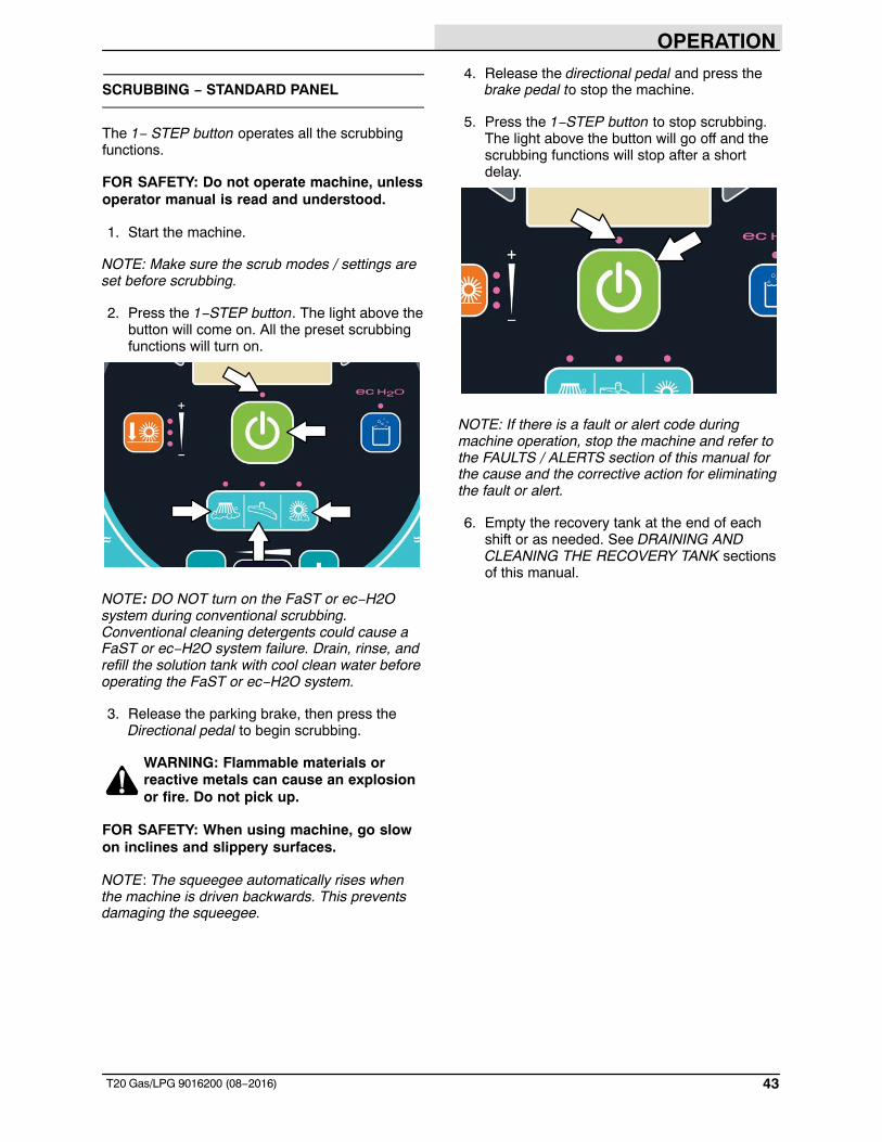
4. Release the directional pedal and press thebrake pedal to stop the machine.
5. Press the 1−STEP button to stop scrubbing.The light above the button will go off and thescrubbing functions will stop after a shortdelay.
NOTE: If there is a fault or alert code duringmachine operation, stop the machine and refer tothe FAULTS / ALERTS section of this manual forthe cause and the corrective action for eliminatingthe fault or alert.
6. Empty the recovery tank at the end of eachshift or as needed. See DRAINING ANDCLEANING THE RECOVERY TANK sectionsof this manual.
OPERATION
44 T20 Gas/LPG 9016200 (08−2016)
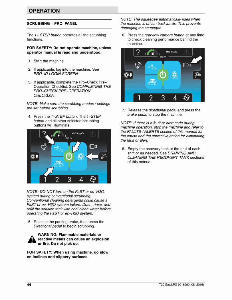
SCRUBBING − PRO−PANEL
The 1− STEP button operates all the scrubbingfunctions.
FOR SAFETY: Do not operate machine, unlessoperator manual is read and understood.
1. Start the machine.
2. If applicable, log into the machine. SeePRO−ID LOGIN SCREEN.
3. If applicable, complete the Pro−Check Pre−Operation Checklist. See COMPLETING THEPRO−CHECK PRE−OPERATIONCHECKLIST.
NOTE: Make sure the scrubbing modes / settingsare set before scrubbing.
4. Press the 1−STEP button. The 1−STEPbutton and all other selected scrubbingbuttons will illuminate.
NOTE: DO NOT turn on the FaST or ec−H2Osystem during conventional scrubbing.Conventional cleaning detergents could cause aFaST or ec−H2O system failure. Drain, rinse, andrefill the solution tank with cool clean water beforeoperating the FaST or ec−H2O system.
5. Release the parking brake, then press theDirectional pedal to begin scrubbing.
WARNING: Flammable materials orreactive metals can cause an explosionor fire. Do not pick up.
FOR SAFETY: When using machine, go slowon inclines and slippery surfaces.
NOTE: The squeegee automatically rises whenthe machine is driven backwards. This preventsdamaging the squeegee.
6. Press the rearview camera button at any timeto check cleaning performance behind themachine.
7. Release the directional pedal and press thebrake pedal to stop the machine.
NOTE: If there is a fault or alert code duringmachine operation, stop the machine and refer tothe FAULTS / ALERTS section of this manual forthe cause and the corrective action for eliminatingthe fault or alert.
8. Empty the recovery tank at the end of eachshift or as needed. See DRAINING ANDCLEANING THE RECOVERY TANK sectionsof this manual.
OPERATION
45T20 Gas/LPG 9016200 (08−2016)
DOUBLE SCRUBBING
Double scrubbing is the process of making two ormore passes over a heavily soiled area. The firstpass is made with the rear and side squeegeesraised to allow the solution to soak into the floor.Use the double scrubbing method to clean heavilysoiled areas.
Double scrubbing can be performed using the FaST SCRUBBING SYSTEM (option), ec−H2O SCRUBBING SYSTEM (option) or CONVENTIONAL SCRUBBING methods.
Side brush option: Before double scrubbing,remove the side brush bumper. Pull the pins andremove the squeegee bumper.
NOTE: Make sure the scrubbing modes / settingsare set before scrubbing.
Machines equipped with standard panel:Press the 1−STEP button, and then the Scrubvacuum fan/squeegee button. The light above theScrub vacuum fan/squeegee button will turn off,the squeegee will rise, and the vacuum fan willstop operating. Scrub the heavily soiled area.
Standard Panel
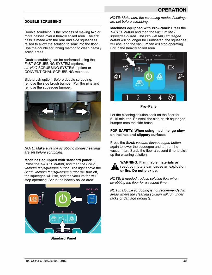
NOTE: Make sure the scrubbing modes / settingsare set before scrubbing.
Machines equipped with Pro−Panel: Press the1−STEP button and then the vacuum fan /squeegee button. The vacuum fan / squeegeebutton will no longer be illuminated, the squeegeewill rise, and the vacuum fan will stop operating.Scrub the heavily soiled area.
Pro−Panel
Let the cleaning solution soak on the floor for5−15 minutes. Reinstall the side brush squeegeebumper onto the side brush.
FOR SAFETY: When using machine, go slowon inclines and slippery surfaces.
Press the Scrub vacuum fan/squeegee buttonagain to lower the squeegee and turn on thevacuum fan. Scrub the floor a second time to pickup the cleaning solution.
WARNING: Flammable materials orreactive metals can cause an explosionor fire. Do not pick up.
NOTE: If needed, reduce solution flow whenscrubbing the floor for a second time.
NOTE: Double scrubbing is not recommended inareas where the cleaning solution will run underracks or damage products.
OPERATION
46 T20 Gas/LPG 9016200 (08−2016)
WATER PICKUP MODE (NO SCRUBBING)
The machine can be used to pick up water ornon−flammable liquid spills without scrubbing.
WARNING: Flammable materials orreactive metals can cause an explosionor fire. Do not pick up.
Before picking up water or non−flammable liquidspills, make sure the 1−STEP button is activatedand all other cleaning functions are off.
Machines equipped with standard controlpanel: Press the scrubbing vacuum fan /squeegee button. The light above the button willilluminate, the squeegee will lower, and thevacuum fan will start operating. Pick up the wateror non−flammable liquid spill.
Standard Panel
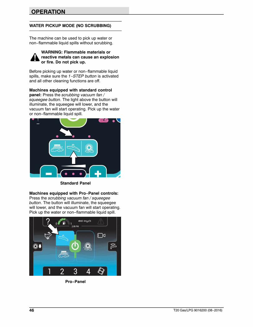
Machines equipped with Pro−Panel controls:Press the scrubbing vacuum fan / squeegeebutton. The button will illuminate, the squeegeewill lower, and the vacuum fan will start operating.Pick up the water or non−flammable liquid spill.
Pro−Panel
OPERATION
47T20 Gas/LPG 9016200 (08−2016)
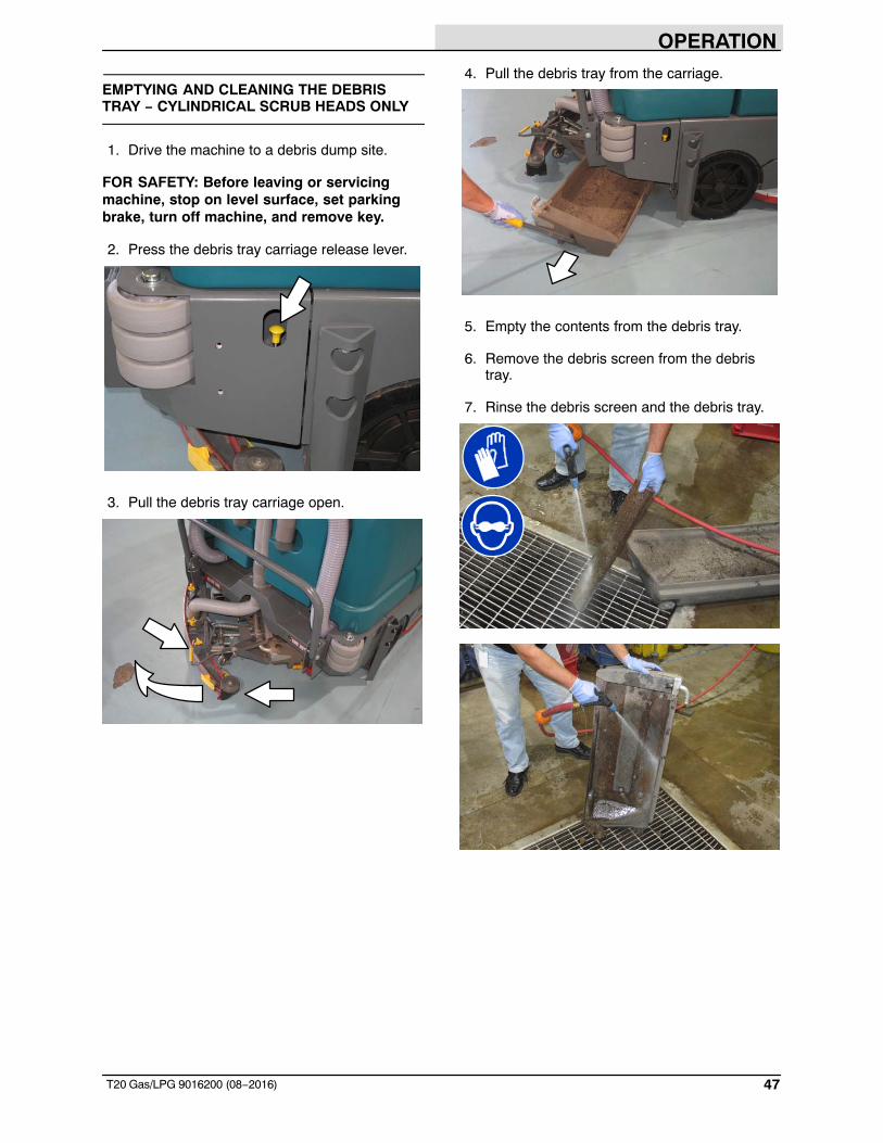
EMPTYING AND CLEANING THE DEBRISTRAY − CYLINDRICAL SCRUB HEADS ONLY
1. Drive the machine to a debris dump site.
FOR SAFETY: Before leaving or servicingmachine, stop on level surface, set parkingbrake, turn off machine, and remove key.
2. Press the debris tray carriage release lever.
3. Pull the debris tray carriage open.
4. Pull the debris tray from the carriage.
5. Empty the contents from the debris tray.
6. Remove the debris screen from the debristray.
7. Rinse the debris screen and the debris tray.
OPERATION
48 T20 Gas/LPG 9016200 (08−2016)
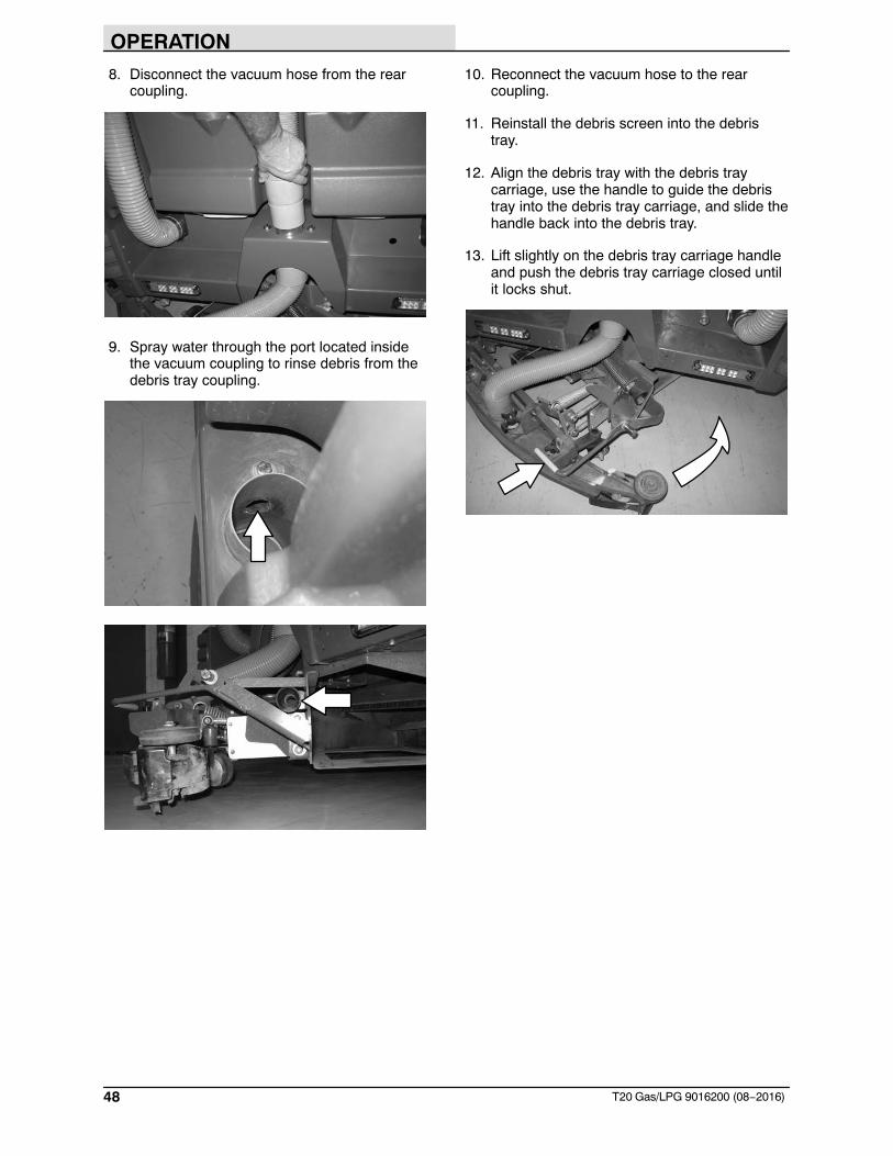
8. Disconnect the vacuum hose from the rearcoupling.
9. Spray water through the port located insidethe vacuum coupling to rinse debris from thedebris tray coupling.
10. Reconnect the vacuum hose to the rearcoupling.
11. Reinstall the debris screen into the debristray.
12. Align the debris tray with the debris traycarriage, use the handle to guide the debristray into the debris tray carriage, and slide thehandle back into the debris tray.
13. Lift slightly on the debris tray carriage handleand push the debris tray carriage closed untilit locks shut.
OPERATION
49T20 Gas/LPG 9016200 (08−2016)
DRAINING AND CLEANING THE RECOVERYTANK
Drain and clean the recovery tank daily or whenthe recovery tank full indicator comes on.
Clean the outside of the recovery tank with vinylcleaner.
FOR SAFETY: Before leaving or servicingmachine, stop on level surface, set parkingbrake, turn off machine, and remove key.
DRAINING THE RECOVERY TANK WITH THEDRAIN HOSE
1. Lift the recovery tank cover.
2. Place the recovery tank drain hose nozzlenext to a floor drain.
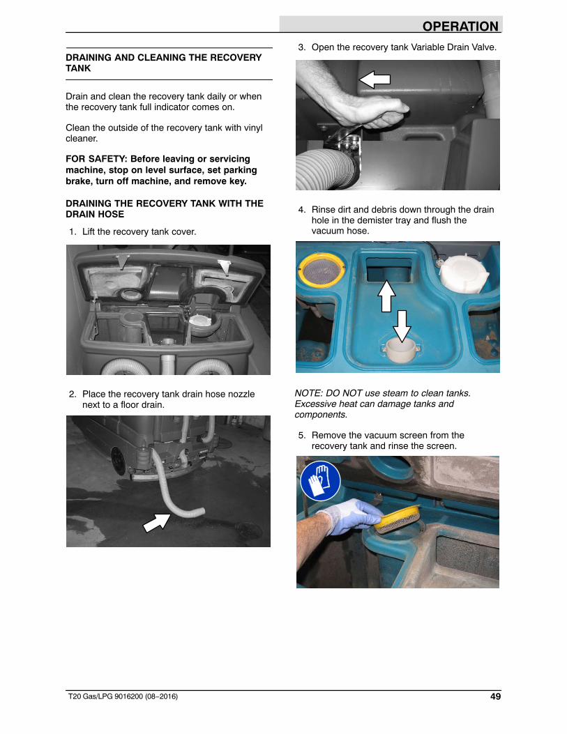
3. Open the recovery tank Variable Drain Valve.
4. Rinse dirt and debris down through the drainhole in the demister tray and flush thevacuum hose.
NOTE: DO NOT use steam to clean tanks.Excessive heat can damage tanks andcomponents.
5. Remove the vacuum screen from therecovery tank and rinse the screen.
OPERATION
50 T20 Gas/LPG 9016200 (08−2016)
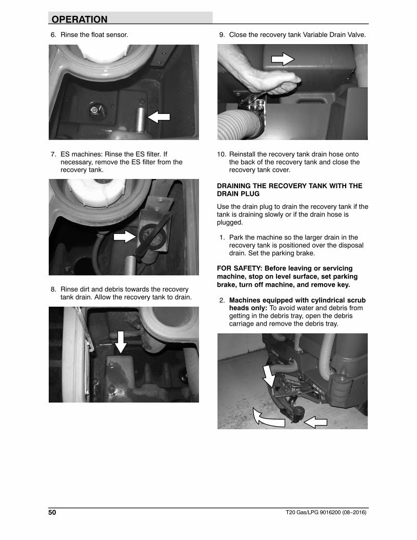
6. Rinse the float sensor.
7. ES machines: Rinse the ES filter. Ifnecessary, remove the ES filter from therecovery tank.
8. Rinse dirt and debris towards the recoverytank drain. Allow the recovery tank to drain.
9. Close the recovery tank Variable Drain Valve.
10. Reinstall the recovery tank drain hose ontothe back of the recovery tank and close therecovery tank cover.
DRAINING THE RECOVERY TANK WITH THEDRAIN PLUG
Use the drain plug to drain the recovery tank if thetank is draining slowly or if the drain hose isplugged.
1. Park the machine so the larger drain in therecovery tank is positioned over the disposaldrain. Set the parking brake.
FOR SAFETY: Before leaving or servicingmachine, stop on level surface, set parkingbrake, turn off machine, and remove key.
2. Machines equipped with cylindrical scrubheads only: To avoid water and debris fromgetting in the debris tray, open the debriscarriage and remove the debris tray.
OPERATION
51T20 Gas/LPG 9016200 (08−2016)
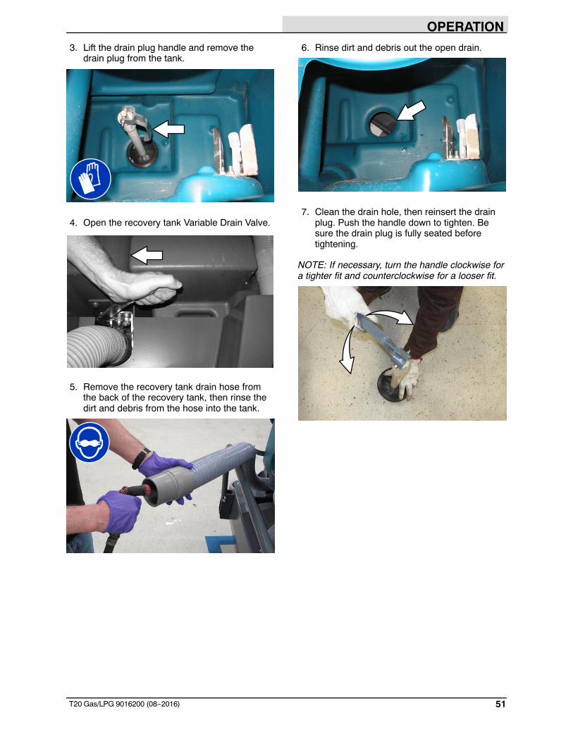
3. Lift the drain plug handle and remove thedrain plug from the tank.
4. Open the recovery tank Variable Drain Valve.
5. Remove the recovery tank drain hose fromthe back of the recovery tank, then rinse thedirt and debris from the hose into the tank.
6. Rinse dirt and debris out the open drain.
7. Clean the drain hole, then reinsert the drainplug. Push the handle down to tighten. Besure the drain plug is fully seated beforetightening.
NOTE: If necessary, turn the handle clockwise fora tighter fit and counterclockwise for a looser fit.
OPERATION
52 T20 Gas/LPG 9016200 (08−2016)
8. Close the recovery tank Variable Drain Valve.
9. Reinstall the recovery tank drain hose ontothe back of the recovery tank.
10. Machines equipped with cylindrical scrubheads only: Reinstall the debris tray into thedebris tray carriage and close the carriage.
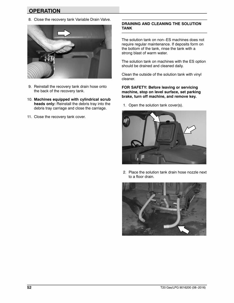
11. Close the recovery tank cover.
DRAINING AND CLEANING THE SOLUTIONTANK
The solution tank on non−ES machines does notrequire regular maintenance. If deposits form onthe bottom of the tank, rinse the tank with astrong blast of warm water.
The solution tank on machines with the ES optionshould be drained and cleaned daily.
Clean the outside of the solution tank with vinylcleaner.
FOR SAFETY: Before leaving or servicingmachine, stop on level surface, set parkingbrake, turn off machine, and remove key.
1. Open the solution tank cover(s).
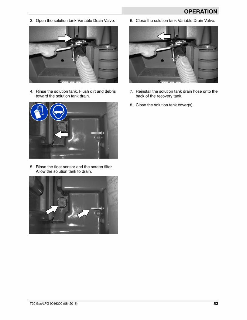
2. Place the solution tank drain hose nozzle nextto a floor drain.
OPERATION
53T20 Gas/LPG 9016200 (08−2016)
3. Open the solution tank Variable Drain Valve.
4. Rinse the solution tank. Flush dirt and debristoward the solution tank drain.
5. Rinse the float sensor and the screen filter.Allow the solution tank to drain.
6. Close the solution tank Variable Drain Valve.
7. Reinstall the solution tank drain hose onto theback of the recovery tank.
8. Close the solution tank cover(s).
OPERATION
54 T20 Gas/LPG 9016200 (08−2016)
FAULTS / ALERTS
The operator will receive a fault / alert warningwhen there is a mechanical / electronic issue withthe machine.
To reset the fault / alert indicators, turn off themachine and then eliminate the cause of the fault/ alert. The fault / alert indicator will reset whenthe machine is restarted.
Refer to the fault / alert indicators table todetermine the cause and remedy for the fault /alert.
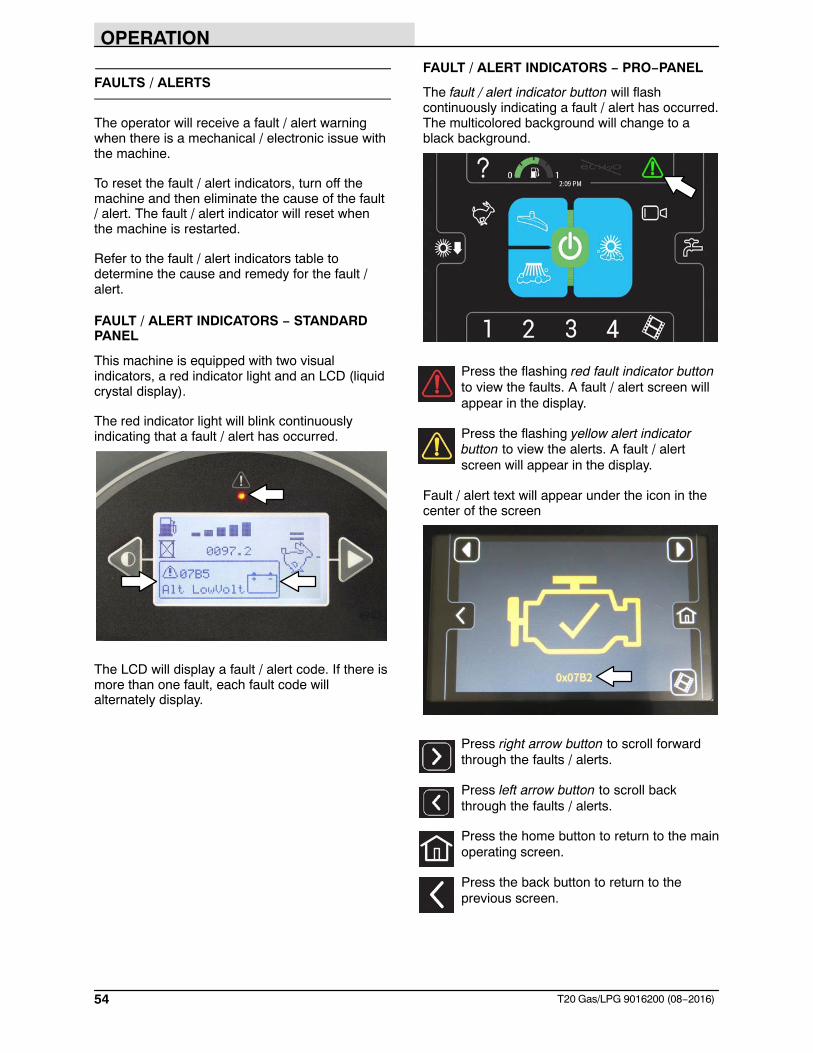
FAULT / ALERT INDICATORS − STANDARDPANEL
This machine is equipped with two visualindicators, a red indicator light and an LCD (liquidcrystal display).
The red indicator light will blink continuouslyindicating that a fault / alert has occurred.
The LCD will display a fault / alert code. If there ismore than one fault, each fault code willalternately display.
FAULT / ALERT INDICATORS − PRO−PANEL
The fault / alert indicator button will flashcontinuously indicating a fault / alert has occurred.The multicolored background will change to ablack background.
Press the flashing red fault indicator buttonto view the faults. A fault / alert screen willappear in the display.
Press the flashing yellow alert indicatorbutton to view the alerts. A fault / alertscreen will appear in the display.
Fault / alert text will appear under the icon in thecenter of the screen
Press right arrow button to scroll forwardthrough the faults / alerts.
Press left arrow button to scroll backthrough the faults / alerts.
Press the home button to return to the mainoperating screen.
Press the back button to return to theprevious screen.
OPERATION
55T20 Gas/LPG 9016200 (08−2016)
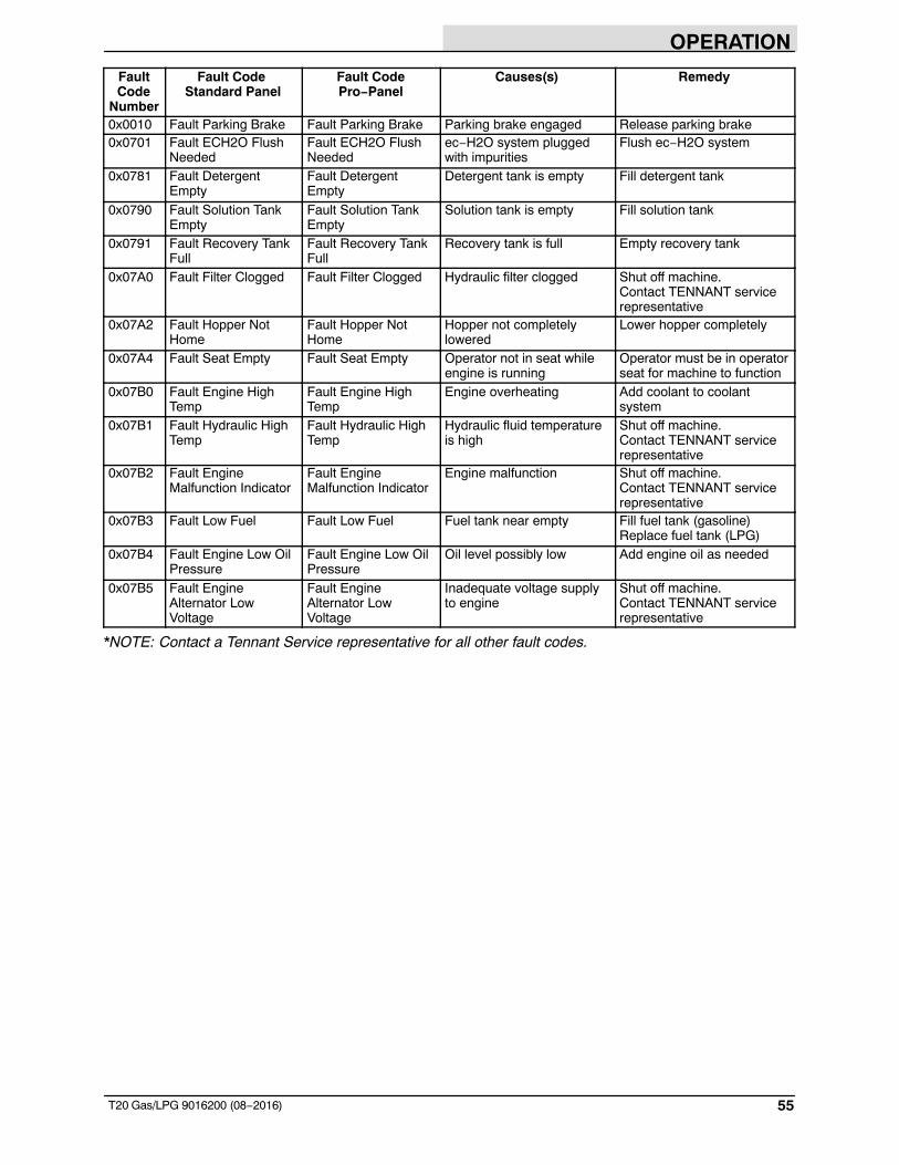
FaultCode
Number
Fault Code Standard Panel
Fault CodePro−Panel
Causes(s) Remedy
0x0010 Fault Parking Brake Fault Parking Brake Parking brake engaged Release parking brake0x0701 Fault ECH2O Flush
NeededFault ECH2O FlushNeeded
ec−H2O system pluggedwith impurities
Flush ec−H2O system
0x0781 Fault DetergentEmpty
Fault DetergentEmpty
Detergent tank is empty Fill detergent tank
0x0790 Fault Solution TankEmpty
Fault Solution TankEmpty
Solution tank is empty Fill solution tank
0x0791 Fault Recovery TankFull
Fault Recovery TankFull
Recovery tank is full Empty recovery tank
0x07A0 Fault Filter Clogged Fault Filter Clogged Hydraulic filter clogged Shut off machine.Contact TENNANT servicerepresentative
0x07A2 Fault Hopper NotHome
Fault Hopper NotHome
Hopper not completelylowered
Lower hopper completely
0x07A4 Fault Seat Empty Fault Seat Empty Operator not in seat whileengine is running
Operator must be in operatorseat for machine to function
0x07B0 Fault Engine HighTemp
Fault Engine HighTemp
Engine overheating Add coolant to coolantsystem
0x07B1 Fault Hydraulic HighTemp
Fault Hydraulic HighTemp
Hydraulic fluid temperatureis high
Shut off machine.Contact TENNANT servicerepresentative
0x07B2 Fault EngineMalfunction Indicator
Fault EngineMalfunction Indicator
Engine malfunction Shut off machine.Contact TENNANT servicerepresentative
0x07B3 Fault Low Fuel Fault Low Fuel Fuel tank near empty Fill fuel tank (gasoline)Replace fuel tank (LPG)
0x07B4 Fault Engine Low OilPressure
Fault Engine Low OilPressure
Oil level possibly low Add engine oil as needed
0x07B5 Fault EngineAlternator LowVoltage
Fault EngineAlternator LowVoltage
Inadequate voltage supplyto engine
Shut off machine.Contact TENNANT servicerepresentative
*NOTE: Contact a Tennant Service representative for all other fault codes.
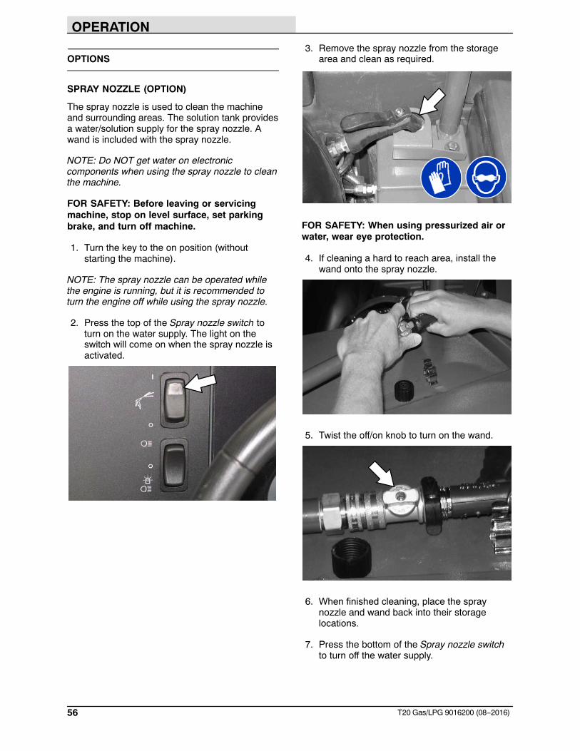
OPERATION
56 T20 Gas/LPG 9016200 (08−2016)
OPTIONS
SPRAY NOZZLE (OPTION)
The spray nozzle is used to clean the machineand surrounding areas. The solution tank providesa water/solution supply for the spray nozzle. Awand is included with the spray nozzle.
NOTE: Do NOT get water on electroniccomponents when using the spray nozzle to cleanthe machine.
FOR SAFETY: Before leaving or servicingmachine, stop on level surface, set parkingbrake, and turn off machine.
1. Turn the key to the on position (withoutstarting the machine).
NOTE: The spray nozzle can be operated whilethe engine is running, but it is recommended toturn the engine off while using the spray nozzle.
2. Press the top of the Spray nozzle switch toturn on the water supply. The light on theswitch will come on when the spray nozzle isactivated.
3. Remove the spray nozzle from the storagearea and clean as required.
FOR SAFETY: When using pressurized air orwater, wear eye protection.
4. If cleaning a hard to reach area, install thewand onto the spray nozzle.
5. Twist the off/on knob to turn on the wand.
6. When finished cleaning, place the spraynozzle and wand back into their storagelocations.
7. Press the bottom of the Spray nozzle switchto turn off the water supply.
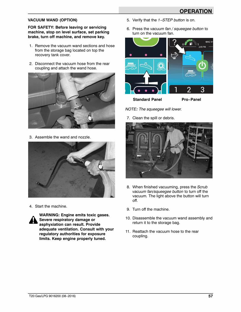
OPERATION
57T20 Gas/LPG 9016200 (08−2016)
VACUUM WAND (OPTION)
FOR SAFETY: Before leaving or servicingmachine, stop on level surface, set parkingbrake, turn off machine, and remove key.
1. Remove the vacuum wand sections and hosefrom the storage bag located on top therecovery tank cover.
2. Disconnect the vacuum hose from the rearcoupling and attach the wand hose.
3. Assemble the wand and nozzle.
4. Start the machine.
WARNING: Engine emits toxic gases.Severe respiratory damage orasphyxiation can result. Provideadequate ventilation. Consult with yourregulatory authorities for exposurelimits. Keep engine properly tuned.
5. Verify that the 1−STEP button is on.
6. Press the vacuum fan / squeegee button toturn on the vacuum fan.
Standard Panel Pro−Panel
NOTE: The squeegee will lower.
7. Clean the spill or debris.
8. When finished vacuuming, press the Scrubvacuum fan/squeegee button to turn off thevacuum. The light above the button will turnoff.
9. Turn off the machine.
10. Disassemble the vacuum wand assembly andreturn it to the storage bag.
11. Reattach the vacuum hose to the rearcoupling.
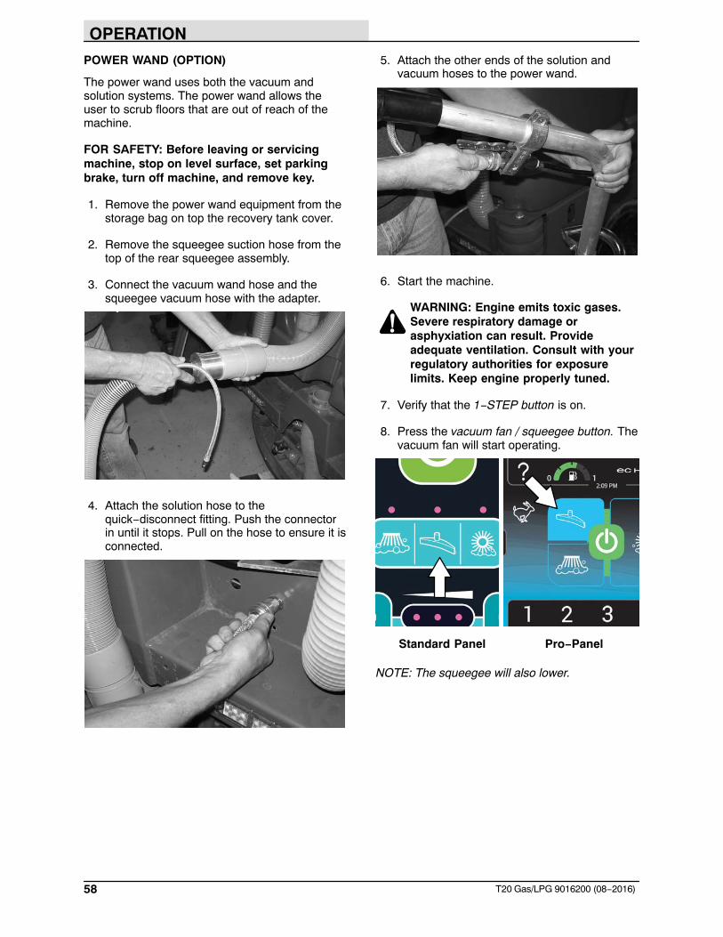
OPERATION
58 T20 Gas/LPG 9016200 (08−2016)
POWER WAND (OPTION)
The power wand uses both the vacuum andsolution systems. The power wand allows theuser to scrub floors that are out of reach of themachine.
FOR SAFETY: Before leaving or servicingmachine, stop on level surface, set parkingbrake, turn off machine, and remove key.
1. Remove the power wand equipment from thestorage bag on top the recovery tank cover.
2. Remove the squeegee suction hose from thetop of the rear squeegee assembly.
3. Connect the vacuum wand hose and thesqueegee vacuum hose with the adapter.
4. Attach the solution hose to thequick−disconnect fitting. Push the connectorin until it stops. Pull on the hose to ensure it isconnected.
5. Attach the other ends of the solution andvacuum hoses to the power wand.
6. Start the machine.
WARNING: Engine emits toxic gases.Severe respiratory damage orasphyxiation can result. Provideadequate ventilation. Consult with yourregulatory authorities for exposurelimits. Keep engine properly tuned.
7. Verify that the 1−STEP button is on.
8. Press the vacuum fan / squeegee button. Thevacuum fan will start operating.
Standard Panel Pro−Panel
NOTE: The squeegee will also lower.
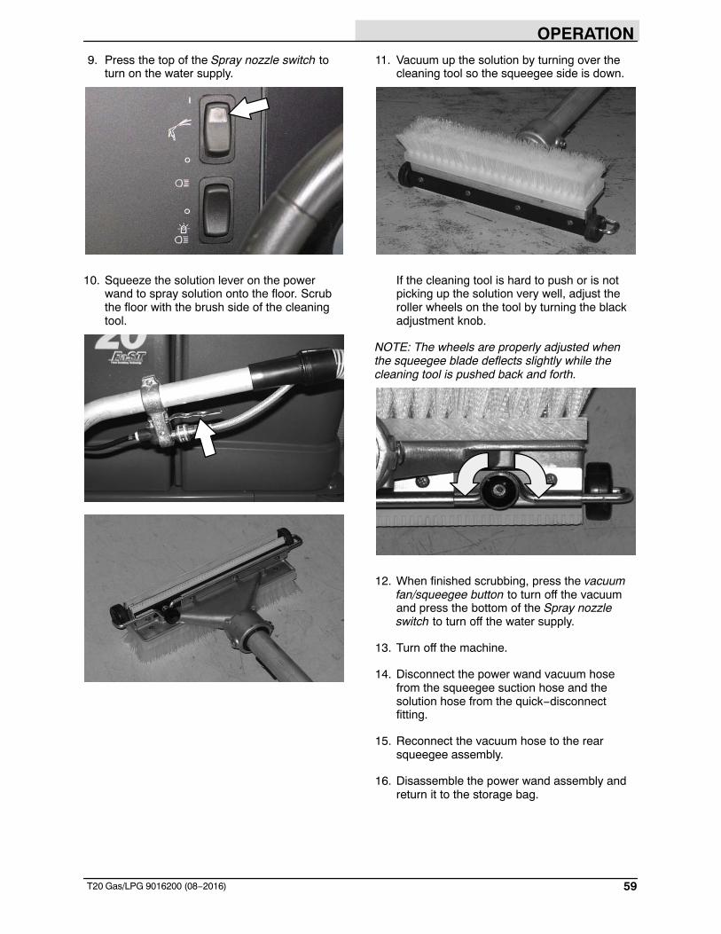
OPERATION
59T20 Gas/LPG 9016200 (08−2016)
9. Press the top of the Spray nozzle switch toturn on the water supply.
10. Squeeze the solution lever on the powerwand to spray solution onto the floor. Scrubthe floor with the brush side of the cleaningtool.
11. Vacuum up the solution by turning over thecleaning tool so the squeegee side is down.
If the cleaning tool is hard to push or is notpicking up the solution very well, adjust theroller wheels on the tool by turning the blackadjustment knob.
NOTE: The wheels are properly adjusted whenthe squeegee blade deflects slightly while thecleaning tool is pushed back and forth.
12. When finished scrubbing, press the vacuumfan/squeegee button to turn off the vacuumand press the bottom of the Spray nozzleswitch to turn off the water supply.
13. Turn off the machine.
14. Disconnect the power wand vacuum hosefrom the squeegee suction hose and thesolution hose from the quick−disconnectfitting.
15. Reconnect the vacuum hose to the rearsqueegee assembly.
16. Disassemble the power wand assembly andreturn it to the storage bag.
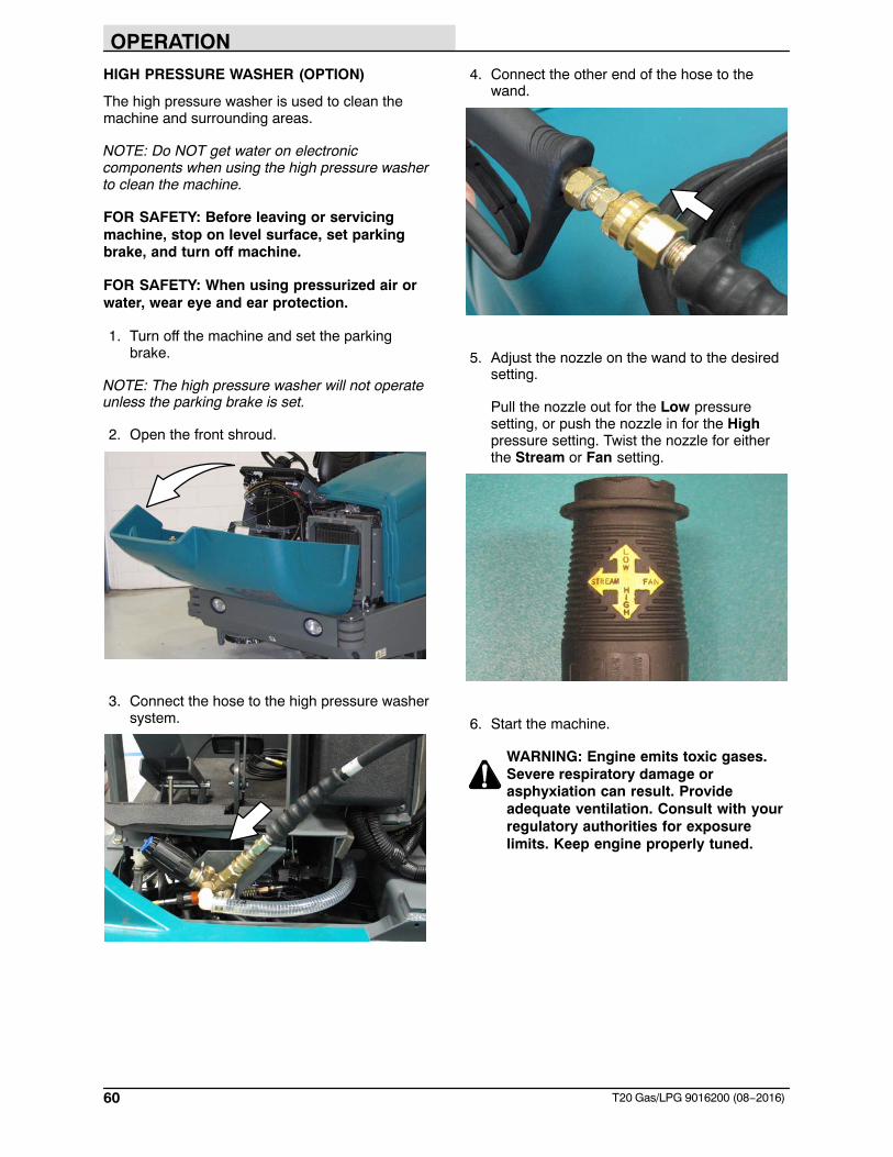
OPERATION
60 T20 Gas/LPG 9016200 (08−2016)
HIGH PRESSURE WASHER (OPTION)
The high pressure washer is used to clean themachine and surrounding areas.
NOTE: Do NOT get water on electroniccomponents when using the high pressure washerto clean the machine.
FOR SAFETY: Before leaving or servicingmachine, stop on level surface, set parkingbrake, and turn off machine.
FOR SAFETY: When using pressurized air orwater, wear eye and ear protection.
1. Turn off the machine and set the parkingbrake.
NOTE: The high pressure washer will not operateunless the parking brake is set.
2. Open the front shroud.
3. Connect the hose to the high pressure washersystem.
4. Connect the other end of the hose to thewand.
5. Adjust the nozzle on the wand to the desiredsetting.
Pull the nozzle out for the Low pressuresetting, or push the nozzle in for the Highpressure setting. Twist the nozzle for eitherthe Stream or Fan setting.
6. Start the machine.
WARNING: Engine emits toxic gases.Severe respiratory damage orasphyxiation can result. Provideadequate ventilation. Consult with yourregulatory authorities for exposurelimits. Keep engine properly tuned.
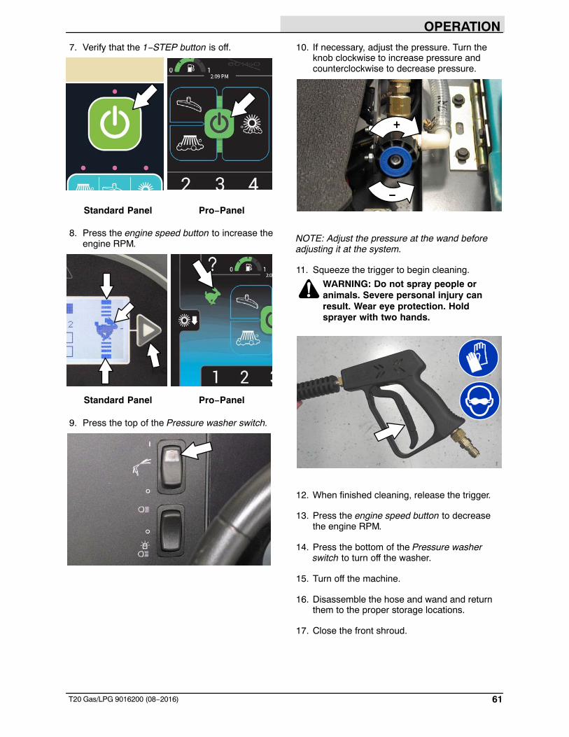
OPERATION
61T20 Gas/LPG 9016200 (08−2016)
7. Verify that the 1−STEP button is off.
Standard Panel Pro−Panel
8. Press the engine speed button to increase theengine RPM.
Standard Panel Pro−Panel
9. Press the top of the Pressure washer switch.
10. If necessary, adjust the pressure. Turn theknob clockwise to increase pressure andcounterclockwise to decrease pressure.
+
−
NOTE: Adjust the pressure at the wand beforeadjusting it at the system.
11. Squeeze the trigger to begin cleaning.
WARNING: Do not spray people oranimals. Severe personal injury canresult. Wear eye protection. Holdsprayer with two hands.
12. When finished cleaning, release the trigger.
13. Press the engine speed button to decreasethe engine RPM.
14. Press the bottom of the Pressure washerswitch to turn off the washer.
15. Turn off the machine.
16. Disassemble the hose and wand and returnthem to the proper storage locations.
17. Close the front shroud.
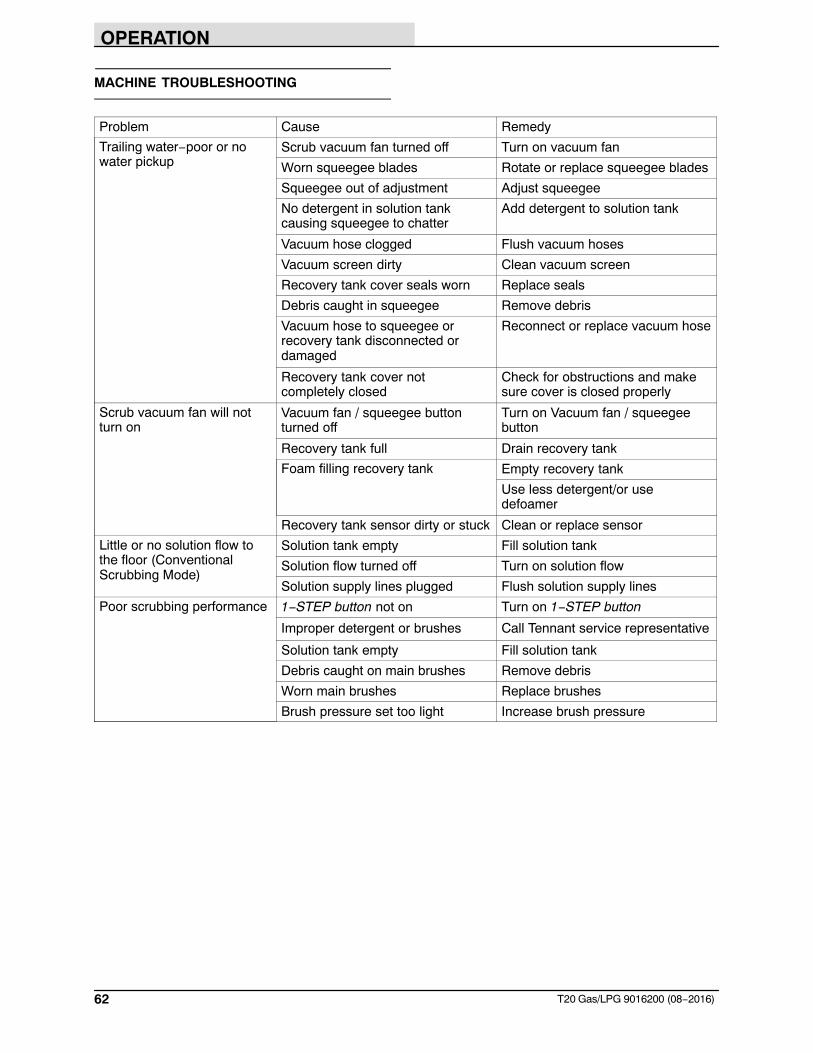
OPERATION
62 T20 Gas/LPG 9016200 (08−2016)
MACHINE TROUBLESHOOTING
Problem Cause Remedy
Trailing water−poor or nowater pickup
Scrub vacuum fan turned off Turn on vacuum fan
Worn squeegee blades Rotate or replace squeegee blades
Squeegee out of adjustment Adjust squeegee
No detergent in solution tankcausing squeegee to chatter
Add detergent to solution tank
Vacuum hose clogged Flush vacuum hoses
Vacuum screen dirty Clean vacuum screen
Recovery tank cover seals worn Replace seals
Debris caught in squeegee Remove debris
Vacuum hose to squeegee orrecovery tank disconnected ordamaged
Reconnect or replace vacuum hose
Recovery tank cover notcompletely closed
Check for obstructions and makesure cover is closed properly
Scrub vacuum fan will notturn on
Vacuum fan / squeegee buttonturned off
Turn on Vacuum fan / squeegeebutton
Recovery tank full Drain recovery tank
Foam filling recovery tank Empty recovery tank
Use less detergent/or usedefoamer
Recovery tank sensor dirty or stuck Clean or replace sensor
Little or no solution flow tothe floor (ConventionalScrubbing Mode)
Solution tank empty Fill solution tank
Solution flow turned off Turn on solution flow
Solution supply lines plugged Flush solution supply lines
Poor scrubbing performance 1−STEP button not on Turn on 1−STEP button
Improper detergent or brushes Call Tennant service representative
Solution tank empty Fill solution tank
Debris caught on main brushes Remove debris
Worn main brushes Replace brushes
Brush pressure set too light Increase brush pressure
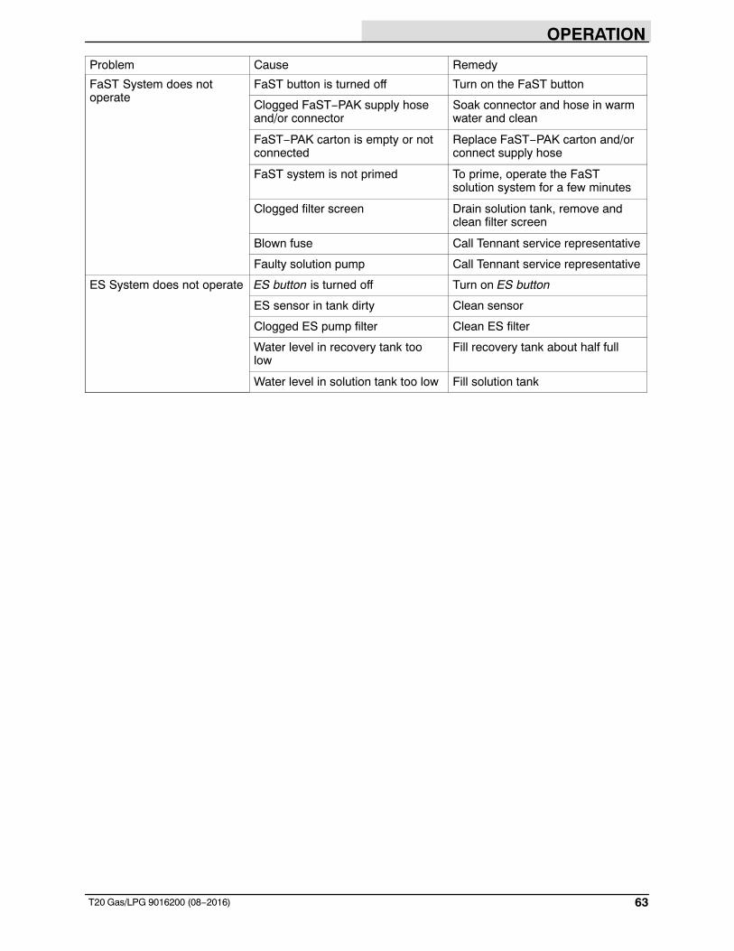
OPERATION
63T20 Gas/LPG 9016200 (08−2016)
Problem Cause Remedy
FaST System does notoperate
FaST button is turned off Turn on the FaST button
Clogged FaST−PAK supply hoseand/or connector
Soak connector and hose in warmwater and clean
FaST−PAK carton is empty or notconnected
Replace FaST−PAK carton and/orconnect supply hose
FaST system is not primed To prime, operate the FaSTsolution system for a few minutes
Clogged filter screen Drain solution tank, remove andclean filter screen
Blown fuse Call Tennant service representative
Faulty solution pump Call Tennant service representative
ES System does not operate ES button is turned off Turn on ES button
ES sensor in tank dirty Clean sensor
Clogged ES pump filter Clean ES filter
Water level in recovery tank toolow
Fill recovery tank about half full
Water level in solution tank too low Fill solution tank
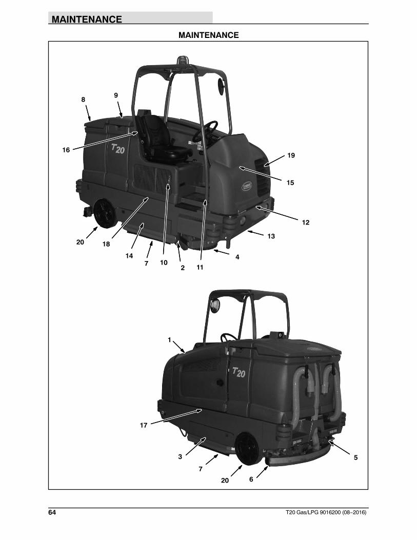
MAINTENANCE
64 T20 Gas/LPG 9016200 (08−2016)
MAINTENANCE
1
2
3
4
5
6
7
89
19
10
12
14
13
15
16
11
17
18
7
20
20
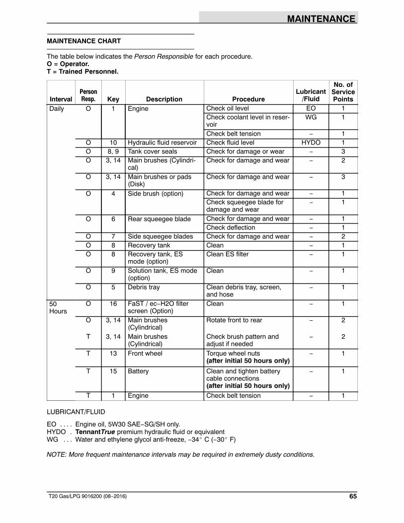
MAINTENANCE
65T20 Gas/LPG 9016200 (08−2016)
MAINTENANCE CHART
The table below indicates the Person Responsible for each procedure.O = Operator.T = Trained Personnel.
IntervalPersonResp. Key Description Procedure
Lubricant/Fluid
No. ofServicePoints
Daily O 1 Engine Check oil level EO 1Check coolant level in reser-voir
WG 1
Check belt tension − 1O 10 Hydraulic fluid reservoir Check fluid level HYDO 1O 8, 9 Tank cover seals Check for damage or wear − 3O 3, 14 Main brushes (Cylindri-
cal)Check for damage and wear − 2
O 3, 14 Main brushes or pads(Disk)
Check for damage and wear − 3
O 4 Side brush (option) Check for damage and wear − 1Check squeegee blade fordamage and wear
− 1
O 6 Rear squeegee blade Check for damage and wear − 1Check deflection − 1
O 7 Side squeegee blades Check for damage and wear − 2O 8 Recovery tank Clean − 1O 8 Recovery tank, ES
mode (option)Clean ES filter − 1
O 9 Solution tank, ES mode(option)
Clean − 1
O 5 Debris tray Clean debris tray, screen,and hose
− 1
50Hours
O 16 FaST / ec−H2O filterscreen (Option)
Clean − 1
O 3, 14 Main brushes (Cylindrical)
Rotate front to rear − 2
T 3, 14 Main brushes (Cylindrical)
Check brush pattern andadjust if needed
− 2
T 13 Front wheel Torque wheel nuts (after initial 50 hours only)
− 1
T 15 Battery Clean and tighten batterycable connections (after initial 50 hours only)
− 1
T 1 Engine Check belt tension − 1
LUBRICANT/FLUID
EO Engine oil, 5W30 SAE−SG/SH only.. . . .HYDO TennantTrue premium hydraulic fluid or equivalent.WG Water and ethylene glycol anti-freeze, −34� C (−30� F). . . NOTE: More frequent maintenance intervals may be required in extremely dusty conditions.
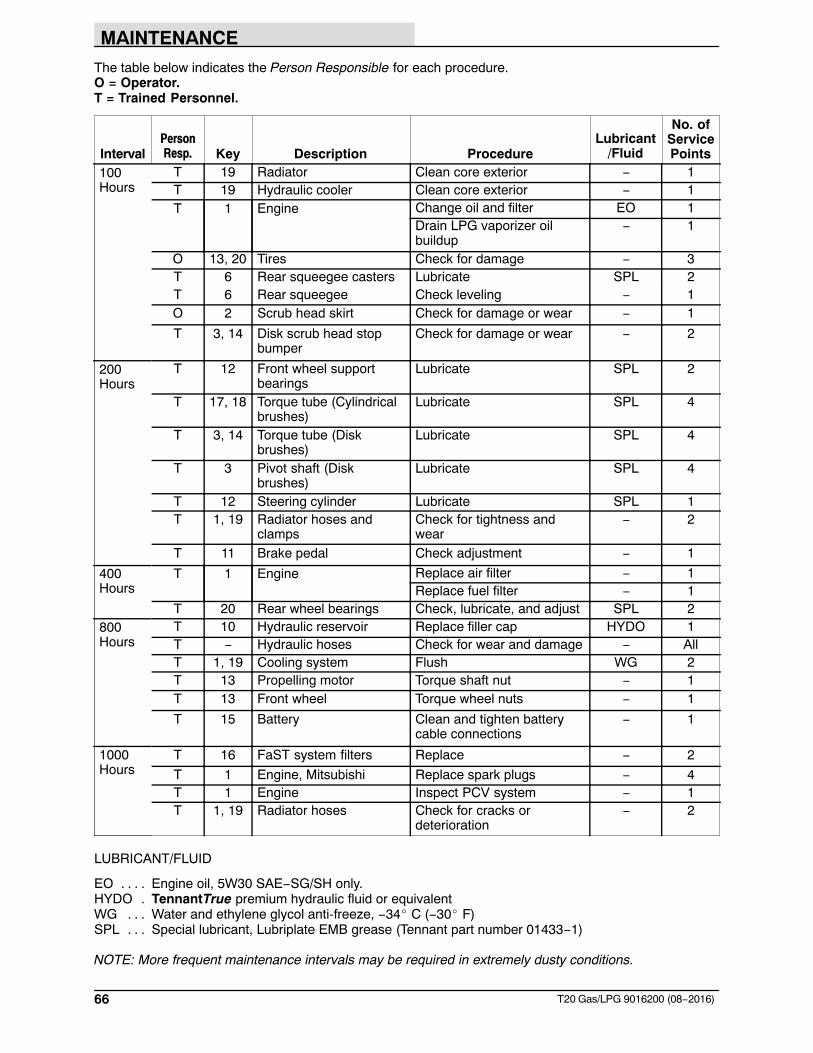
MAINTENANCE
66 T20 Gas/LPG 9016200 (08−2016)
The table below indicates the Person Responsible for each procedure.O = Operator.T = Trained Personnel.
IntervalPersonResp. Key Description Procedure
Lubricant/Fluid
No. ofServicePoints
100Hours
T 19 Radiator Clean core exterior − 1T 19 Hydraulic cooler Clean core exterior − 1T 1 Engine Change oil and filter EO 1
Drain LPG vaporizer oilbuildup
− 1
O 13, 20 Tires Check for damage − 3T 6 Rear squeegee casters Lubricate SPL 2T 6 Rear squeegee Check leveling − 1O 2 Scrub head skirt Check for damage or wear − 1
T 3, 14 Disk scrub head stopbumper
Check for damage or wear − 2
200Hours
T 12 Front wheel supportbearings
Lubricate SPL 2
T 17, 18 Torque tube (Cylindricalbrushes)
Lubricate SPL 4
T 3, 14 Torque tube (Diskbrushes)
Lubricate SPL 4
T 3 Pivot shaft (Diskbrushes)
Lubricate SPL 4
T 12 Steering cylinder Lubricate SPL 1T 1, 19 Radiator hoses and
clampsCheck for tightness andwear
− 2
T 11 Brake pedal Check adjustment − 1
400Hours
T 1 Engine Replace air filter − 1Replace fuel filter − 1
T 20 Rear wheel bearings Check, lubricate, and adjust SPL 2800Hours
T 10 Hydraulic reservoir Replace filler cap HYDO 1T − Hydraulic hoses Check for wear and damage − AllT 1, 19 Cooling system Flush WG 2T 13 Propelling motor Torque shaft nut − 1T 13 Front wheel Torque wheel nuts − 1
T 15 Battery Clean and tighten batterycable connections
− 1
1000Hours
T 16 FaST system filters Replace − 2
T 1 Engine, Mitsubishi Replace spark plugs − 4T 1 Engine Inspect PCV system − 1T 1, 19 Radiator hoses Check for cracks or
deterioration− 2
LUBRICANT/FLUID
EO Engine oil, 5W30 SAE−SG/SH only.. . . .HYDO TennantTrue premium hydraulic fluid or equivalent.WG Water and ethylene glycol anti-freeze, −34� C (−30� F). . .SPL Special lubricant, Lubriplate EMB grease (Tennant part number 01433−1). . . NOTE: More frequent maintenance intervals may be required in extremely dusty conditions.
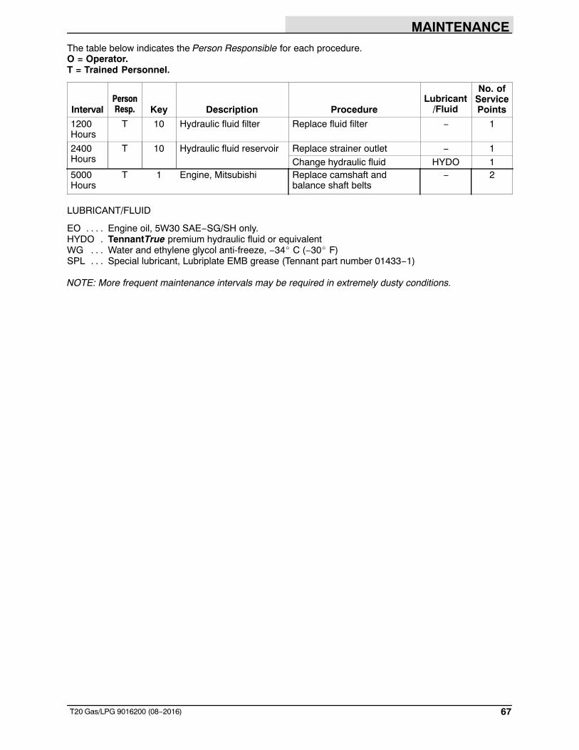
MAINTENANCE
67T20 Gas/LPG 9016200 (08−2016)
The table below indicates the Person Responsible for each procedure.O = Operator.T = Trained Personnel.
IntervalPersonResp. Key Description Procedure
Lubricant/Fluid
No. ofServicePoints
1200Hours
T 10 Hydraulic fluid filter Replace fluid filter − 1
2400Hours
T 10 Hydraulic fluid reservoir Replace strainer outlet − 1Change hydraulic fluid HYDO 1
5000Hours
T 1 Engine, Mitsubishi Replace camshaft andbalance shaft belts
− 2
LUBRICANT/FLUID
EO Engine oil, 5W30 SAE−SG/SH only.. . . .HYDO TennantTrue premium hydraulic fluid or equivalent.WG Water and ethylene glycol anti-freeze, −34� C (−30� F). . .SPL Special lubricant, Lubriplate EMB grease (Tennant part number 01433−1). . . NOTE: More frequent maintenance intervals may be required in extremely dusty conditions.
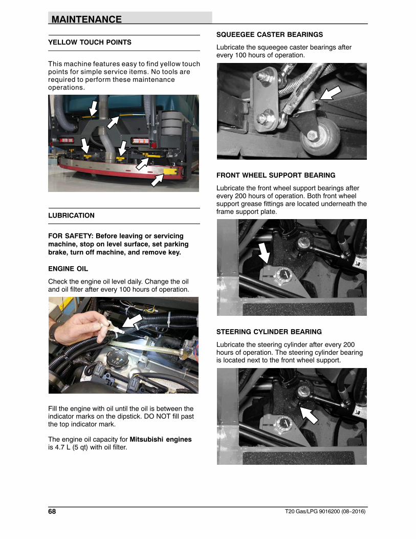
MAINTENANCE
68 T20 Gas/LPG 9016200 (08−2016)
YELLOW TOUCH POINTS
This machine features easy to find yellow touchpoints for simple service items. No tools arerequired to perform these maintenanceoperations.
LUBRICATION
FOR SAFETY: Before leaving or servicingmachine, stop on level surface, set parkingbrake, turn off machine, and remove key.
ENGINE OIL
Check the engine oil level daily. Change the oiland oil filter after every 100 hours of operation.
Fill the engine with oil until the oil is between theindicator marks on the dipstick. DO NOT fill pastthe top indicator mark.
The engine oil capacity for Mitsubishi enginesis 4.7 L (5 qt) with oil filter.
SQUEEGEE CASTER BEARINGS
Lubricate the squeegee caster bearings afterevery 100 hours of operation.
FRONT WHEEL SUPPORT BEARING
Lubricate the front wheel support bearings afterevery 200 hours of operation. Both front wheelsupport grease fittings are located underneath theframe support plate.
STEERING CYLINDER BEARING
Lubricate the steering cylinder after every 200hours of operation. The steering cylinder bearingis located next to the front wheel support.
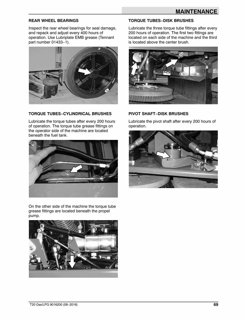
MAINTENANCE
69T20 Gas/LPG 9016200 (08−2016)
REAR WHEEL BEARINGS
Inspect the rear wheel bearings for seal damage,and repack and adjust every 400 hours ofoperation. Use Lubriplate EMB grease (Tennantpart number 01433−1).
TORQUE TUBES−CYLINDRICAL BRUSHES
Lubricate the torque tubes after every 200 hoursof operation. The torque tube grease fittings onthe operator side of the machine are locatedbeneath the fuel tank.
On the other side of the machine the torque tubegrease fittings are located beneath the propelpump.
TORQUE TUBES−DISK BRUSHES
Lubricate the three torque tube fittings after every200 hours of operation. The first two fittings arelocated on each side of the machine and the thirdis located above the center brush.
PIVOT SHAFT−DISK BRUSHES
Lubricate the pivot shaft after every 200 hours ofoperation.
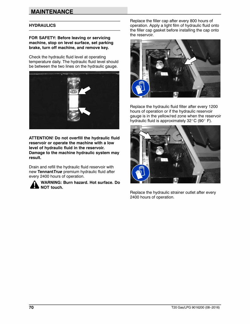
MAINTENANCE
70 T20 Gas/LPG 9016200 (08−2016)
HYDRAULICS
FOR SAFETY: Before leaving or servicingmachine, stop on level surface, set parkingbrake, turn off machine, and remove key.
Check the hydraulic fluid level at operatingtemperature daily. The hydraulic fluid level shouldbe between the two lines on the hydraulic gauge.
ATTENTION! Do not overfill the hydraulic fluidreservoir or operate the machine with a lowlevel of hydraulic fluid in the reservoir.Damage to the machine hydraulic system mayresult.
Drain and refill the hydraulic fluid reservoir withnew TennantTrue premium hydraulic fluid afterevery 2400 hours of operation.
WARNING: Burn hazard. Hot surface. DoNOT touch.
Replace the filler cap after every 800 hours ofoperation. Apply a light film of hydraulic fluid ontothe filler cap gasket before installing the cap ontothe reservoir.
Replace the hydraulic fluid filter after every 1200hours of operation or if the hydraulic reservoirgauge is in the yellow/red zone when the reservoirhydraulic fluid is approximately 32�C (90� F).
Replace the hydraulic strainer outlet after every2400 hours of operation.
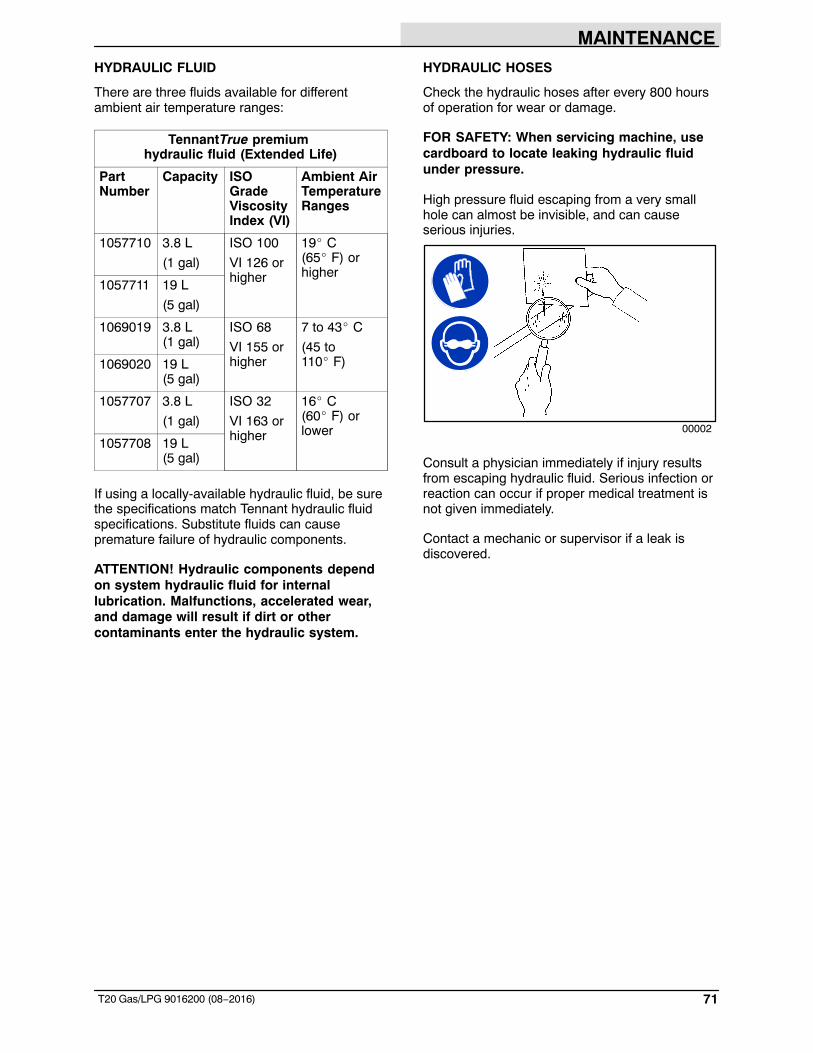
MAINTENANCE
71T20 Gas/LPG 9016200 (08−2016)
HYDRAULIC FLUID
There are three fluids available for differentambient air temperature ranges:
TennantTrue premium hydraulic fluid (Extended Life)
PartNumber
Capacity ISOGradeViscosityIndex (VI)
Ambient AirTemperatureRanges
1057710 3.8 L
(1 gal)
ISO 100
VI 126 orhigher
19� C(65� F) orhigher
1057711 19 L
(5 gal)
1069019 3.8 L (1 gal)
ISO 68
VI 155 orhigher
7 to 43� C
(45 to110� F)1069020 19 L
(5 gal)
1057707 3.8 L
(1 gal)
ISO 32
VI 163 orhigher
16� C(60� F) orlower
1057708 19 L (5 gal)
If using a locally-available hydraulic fluid, be surethe specifications match Tennant hydraulic fluidspecifications. Substitute fluids can causepremature failure of hydraulic components.
ATTENTION! Hydraulic components dependon system hydraulic fluid for internallubrication. Malfunctions, accelerated wear,and damage will result if dirt or othercontaminants enter the hydraulic system.
HYDRAULIC HOSES
Check the hydraulic hoses after every 800 hoursof operation for wear or damage.
FOR SAFETY: When servicing machine, usecardboard to locate leaking hydraulic fluidunder pressure.
High pressure fluid escaping from a very smallhole can almost be invisible, and can causeserious injuries.
00002
Consult a physician immediately if injury resultsfrom escaping hydraulic fluid. Serious infection orreaction can occur if proper medical treatment isnot given immediately.
Contact a mechanic or supervisor if a leak isdiscovered.
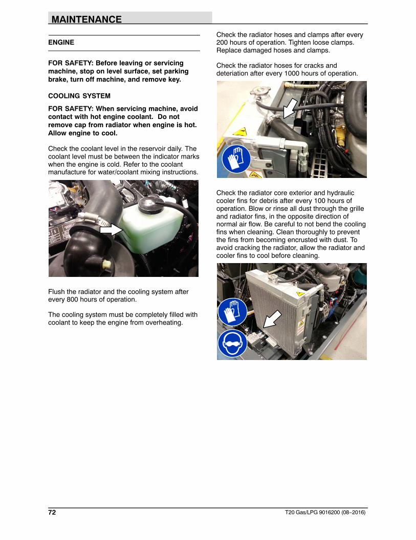
MAINTENANCE
72 T20 Gas/LPG 9016200 (08−2016)
ENGINE
FOR SAFETY: Before leaving or servicingmachine, stop on level surface, set parkingbrake, turn off machine, and remove key.
COOLING SYSTEM
FOR SAFETY: When servicing machine, avoidcontact with hot engine coolant. Do notremove cap from radiator when engine is hot.Allow engine to cool.
Check the coolant level in the reservoir daily. Thecoolant level must be between the indicator markswhen the engine is cold. Refer to the coolantmanufacture for water/coolant mixing instructions.
Flush the radiator and the cooling system afterevery 800 hours of operation.
The cooling system must be completely filled withcoolant to keep the engine from overheating.
Check the radiator hoses and clamps after every200 hours of operation. Tighten loose clamps.Replace damaged hoses and clamps.
Check the radiator hoses for cracks anddeteriation after every 1000 hours of operation.
Check the radiator core exterior and hydrauliccooler fins for debris after every 100 hours ofoperation. Blow or rinse all dust through the grilleand radiator fins, in the opposite direction ofnormal air flow. Be careful to not bend the coolingfins when cleaning. Clean thoroughly to preventthe fins from becoming encrusted with dust. Toavoid cracking the radiator, allow the radiator andcooler fins to cool before cleaning.
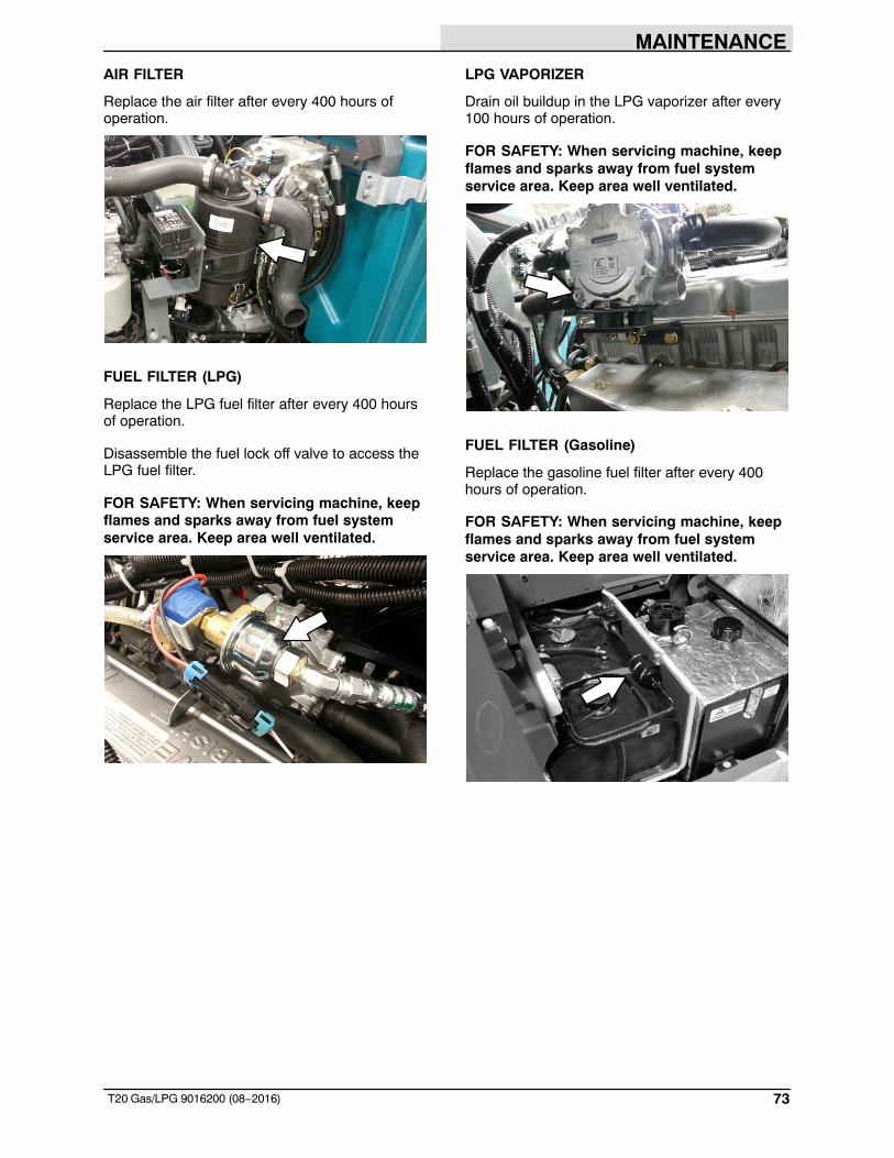
MAINTENANCE
73T20 Gas/LPG 9016200 (08−2016)
AIR FILTER
Replace the air filter after every 400 hours ofoperation.
FUEL FILTER (LPG)
Replace the LPG fuel filter after every 400 hoursof operation.
Disassemble the fuel lock off valve to access theLPG fuel filter.
FOR SAFETY: When servicing machine, keepflames and sparks away from fuel systemservice area. Keep area well ventilated.
LPG VAPORIZER
Drain oil buildup in the LPG vaporizer after every100 hours of operation.
FOR SAFETY: When servicing machine, keepflames and sparks away from fuel systemservice area. Keep area well ventilated.
FUEL FILTER (Gasoline)
Replace the gasoline fuel filter after every 400hours of operation.
FOR SAFETY: When servicing machine, keepflames and sparks away from fuel systemservice area. Keep area well ventilated.
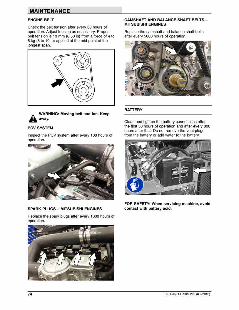
MAINTENANCE
74 T20 Gas/LPG 9016200 (08−2016)
ENGINE BELT
Check the belt tension after every 50 hours ofoperation. Adjust tension as necessary. Properbelt tension is 13 mm (0.50 in) from a force of 4 to5 kg (8 to 10 lb) applied at the mid-point of thelongest span.
WARNING: Moving belt and fan. Keepaway.
PCV SYSTEM
Inspect the PCV system after every 100 hours ofoperation.
SPARK PLUGS − MITSUBISHI ENGINES
Replace the spark plugs after every 1000 hours ofoperation.
CAMSHAFT AND BALANCE SHAFT BELTS −MITSUBISHI ENGINES
Replace the camshaft and balance shaft beltsafter every 5000 hours of operation.
BATTERY
Clean and tighten the battery connections afterthe first 50 hours of operation and after every 800hours after that. Do not remove the vent plugsfrom the battery or add water to the battery.
FOR SAFETY: When servicing machine, avoidcontact with battery acid.
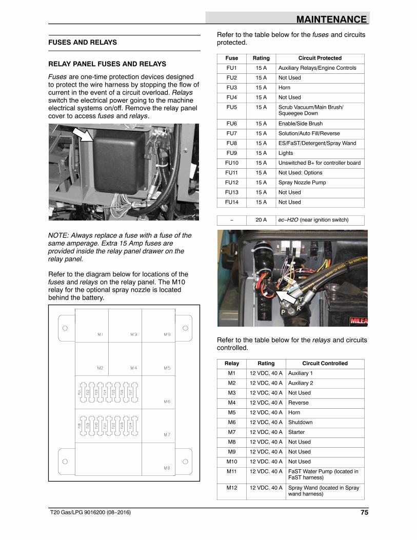
MAINTENANCE
75T20 Gas/LPG 9016200 (08−2016)
FUSES AND RELAYS
RELAY PANEL FUSES AND RELAYS
Fuses are one-time protection devices designedto protect the wire harness by stopping the flow ofcurrent in the event of a circuit overload. Relaysswitch the electrical power going to the machineelectrical systems on/off. Remove the relay panelcover to access fuses and relays.
NOTE: Always replace a fuse with a fuse of thesame amperage. Extra 15 Amp fuses areprovided inside the relay panel drawer on therelay panel.
Refer to the diagram below for locations of thefuses and relays on the relay panel. The M10relay for the optional spray nozzle is locatedbehind the battery.
Refer to the table below for the fuses and circuitsprotected.
Fuse Rating Circuit Protected
FU1 15 A Auxiliary Relays/Engine Controls
FU2 15 A Not Used
FU3 15 A Horn
FU4 15 A Not Used
FU5 15 A Scrub Vacuum/Main Brush/Squeegee Down
FU6 15 A Enable/Side Brush
FU7 15 A Solution/Auto Fill/Reverse
FU8 15 A ES/FaST/Detergent/Spray Wand
FU9 15 A Lights
FU10 15 A Unswitched B+ for controller board
FU11 15 A Not Used: Options
FU12 15 A Spray Nozzle Pump
FU13 15 A Not Used
FU14 15 A Not Used
− 20 A ec−H2O (near ignition switch)
Refer to the table below for the relays and circuitscontrolled.
Relay Rating Circuit Controlled
M1 12 VDC, 40 A Auxiliary 1
M2 12 VDC, 40 A Auxiliary 2
M3 12 VDC, 40 A Not Used
M4 12 VDC, 40 A Reverse
M5 12 VDC, 40 A Horn
M6 12 VDC, 40 A Shutdown
M7 12 VDC, 40 A Starter
M8 12 VDC, 40 A Not Used
M9 12 VDC, 40 A Not Used
M10 12 VDC. 40 A Not Used
M11 12 VDC. 40 A FaST Water Pump (located inFaST harness)
M12 12 VDC. 40 A Spray Wand (located in Spraywand harness)
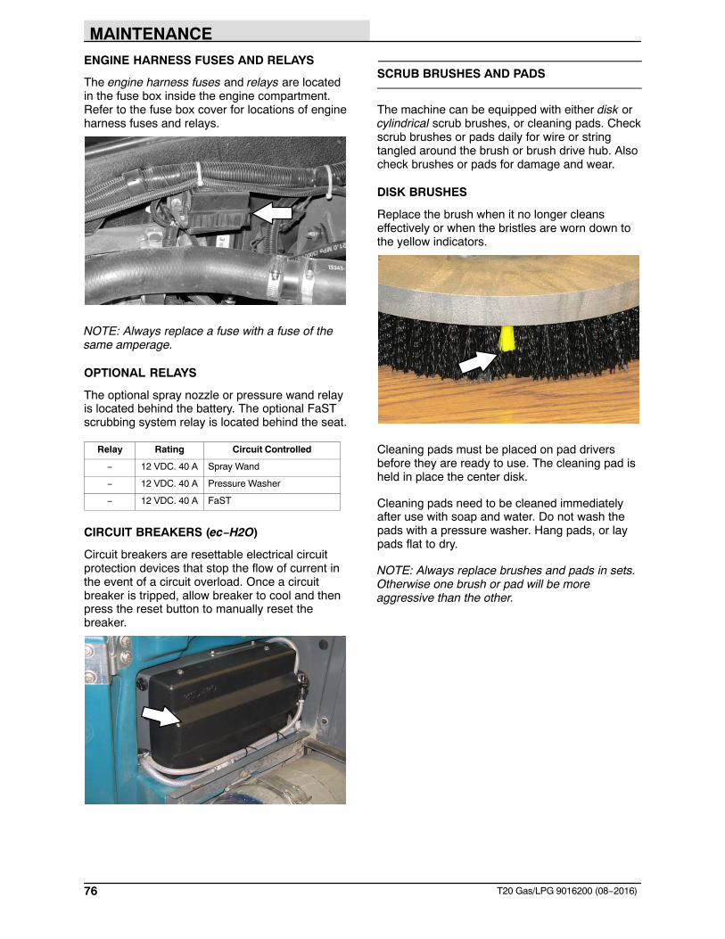
MAINTENANCE
76 T20 Gas/LPG 9016200 (08−2016)
ENGINE HARNESS FUSES AND RELAYS
The engine harness fuses and relays are locatedin the fuse box inside the engine compartment.Refer to the fuse box cover for locations of engineharness fuses and relays.
NOTE: Always replace a fuse with a fuse of thesame amperage.
OPTIONAL RELAYS
The optional spray nozzle or pressure wand relayis located behind the battery. The optional FaSTscrubbing system relay is located behind the seat.
Relay Rating Circuit Controlled
− 12 VDC. 40 A Spray Wand
− 12 VDC. 40 A Pressure Washer
− 12 VDC. 40 A FaST
CIRCUIT BREAKERS (ec−H2O)
Circuit breakers are resettable electrical circuitprotection devices that stop the flow of current inthe event of a circuit overload. Once a circuitbreaker is tripped, allow breaker to cool and thenpress the reset button to manually reset thebreaker.
SCRUB BRUSHES AND PADS
The machine can be equipped with either disk orcylindrical scrub brushes, or cleaning pads. Checkscrub brushes or pads daily for wire or stringtangled around the brush or brush drive hub. Alsocheck brushes or pads for damage and wear.
DISK BRUSHES
Replace the brush when it no longer cleanseffectively or when the bristles are worn down tothe yellow indicators.
Cleaning pads must be placed on pad driversbefore they are ready to use. The cleaning pad isheld in place the center disk.
Cleaning pads need to be cleaned immediatelyafter use with soap and water. Do not wash thepads with a pressure washer. Hang pads, or laypads flat to dry.
NOTE: Always replace brushes and pads in sets.Otherwise one brush or pad will be moreaggressive than the other.
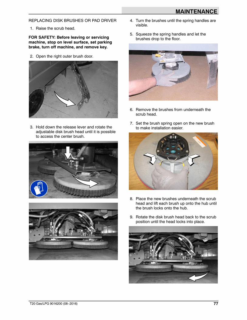
MAINTENANCE
77T20 Gas/LPG 9016200 (08−2016)
REPLACING DISK BRUSHES OR PAD DRIVER
1. Raise the scrub head.
FOR SAFETY: Before leaving or servicingmachine, stop on level surface, set parkingbrake, turn off machine, and remove key.
2. Open the right outer brush door.
3. Hold down the release lever and rotate theadjustable disk brush head until it is possibleto access the center brush.
4. Turn the brushes until the spring handles arevisible.
5. Squeeze the spring handles and let thebrushes drop to the floor.
6. Remove the brushes from underneath thescrub head.
7. Set the brush spring open on the new brushto make installation easier.
8. Place the new brushes underneath the scrubhead and lift each brush up onto the hub untilthe brush locks onto the hub.
9. Rotate the disk brush head back to the scrubposition until the head locks into place.
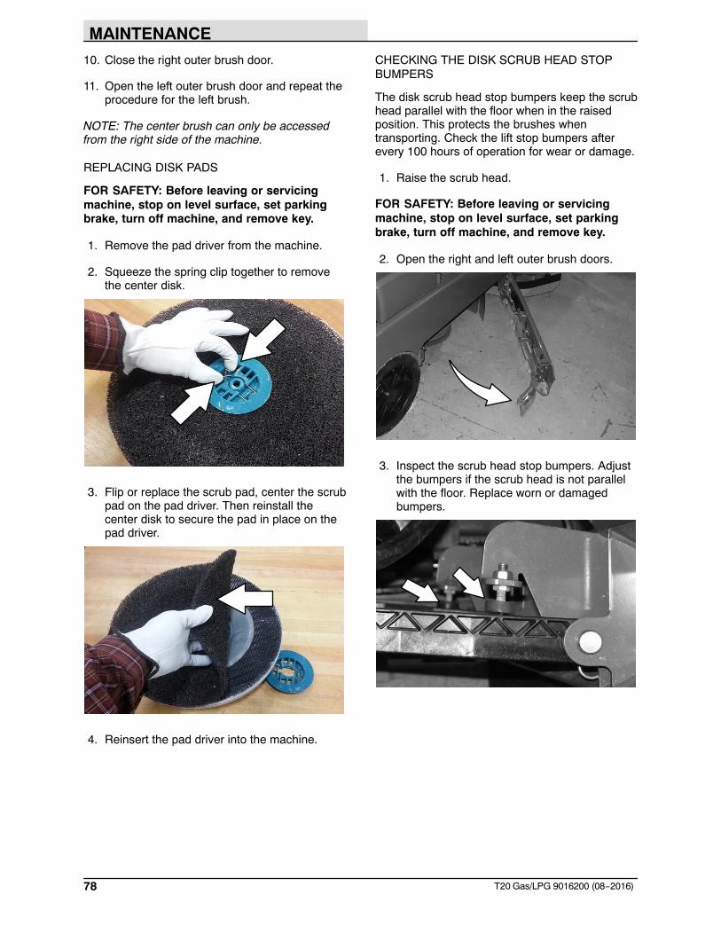
MAINTENANCE
78 T20 Gas/LPG 9016200 (08−2016)
10. Close the right outer brush door.
11. Open the left outer brush door and repeat theprocedure for the left brush.
NOTE: The center brush can only be accessedfrom the right side of the machine.
REPLACING DISK PADS
FOR SAFETY: Before leaving or servicingmachine, stop on level surface, set parkingbrake, turn off machine, and remove key.
1. Remove the pad driver from the machine.
2. Squeeze the spring clip together to removethe center disk.
3. Flip or replace the scrub pad, center the scrubpad on the pad driver. Then reinstall thecenter disk to secure the pad in place on thepad driver.
4. Reinsert the pad driver into the machine.
CHECKING THE DISK SCRUB HEAD STOPBUMPERS
The disk scrub head stop bumpers keep the scrubhead parallel with the floor when in the raisedposition. This protects the brushes whentransporting. Check the lift stop bumpers afterevery 100 hours of operation for wear or damage.
1. Raise the scrub head.
FOR SAFETY: Before leaving or servicingmachine, stop on level surface, set parkingbrake, turn off machine, and remove key.
2. Open the right and left outer brush doors.
3. Inspect the scrub head stop bumpers. Adjustthe bumpers if the scrub head is not parallelwith the floor. Replace worn or damagedbumpers.
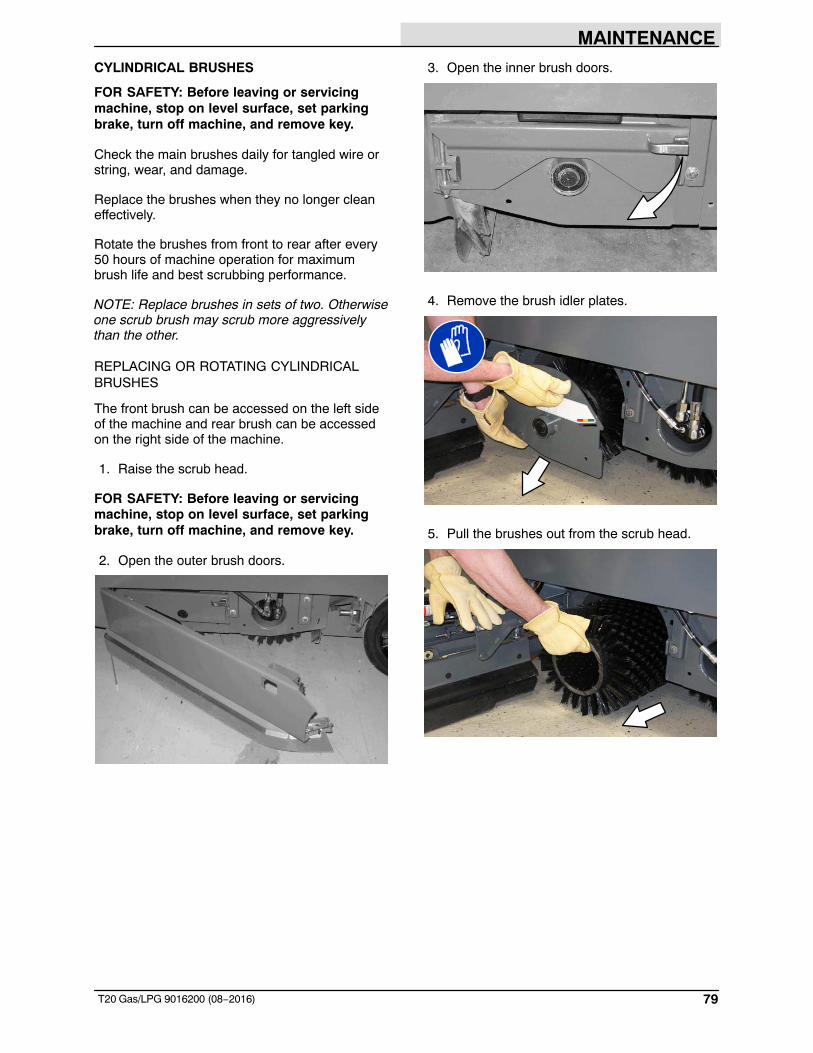
MAINTENANCE
79T20 Gas/LPG 9016200 (08−2016)
CYLINDRICAL BRUSHES
FOR SAFETY: Before leaving or servicingmachine, stop on level surface, set parkingbrake, turn off machine, and remove key.
Check the main brushes daily for tangled wire orstring, wear, and damage.
Replace the brushes when they no longer cleaneffectively.
Rotate the brushes from front to rear after every50 hours of machine operation for maximumbrush life and best scrubbing performance.
NOTE: Replace brushes in sets of two. Otherwiseone scrub brush may scrub more aggressivelythan the other.
REPLACING OR ROTATING CYLINDRICALBRUSHES
The front brush can be accessed on the left sideof the machine and rear brush can be accessedon the right side of the machine.
1. Raise the scrub head.
FOR SAFETY: Before leaving or servicingmachine, stop on level surface, set parkingbrake, turn off machine, and remove key.
2. Open the outer brush doors.
3. Open the inner brush doors.
4. Remove the brush idler plates.
5. Pull the brushes out from the scrub head.
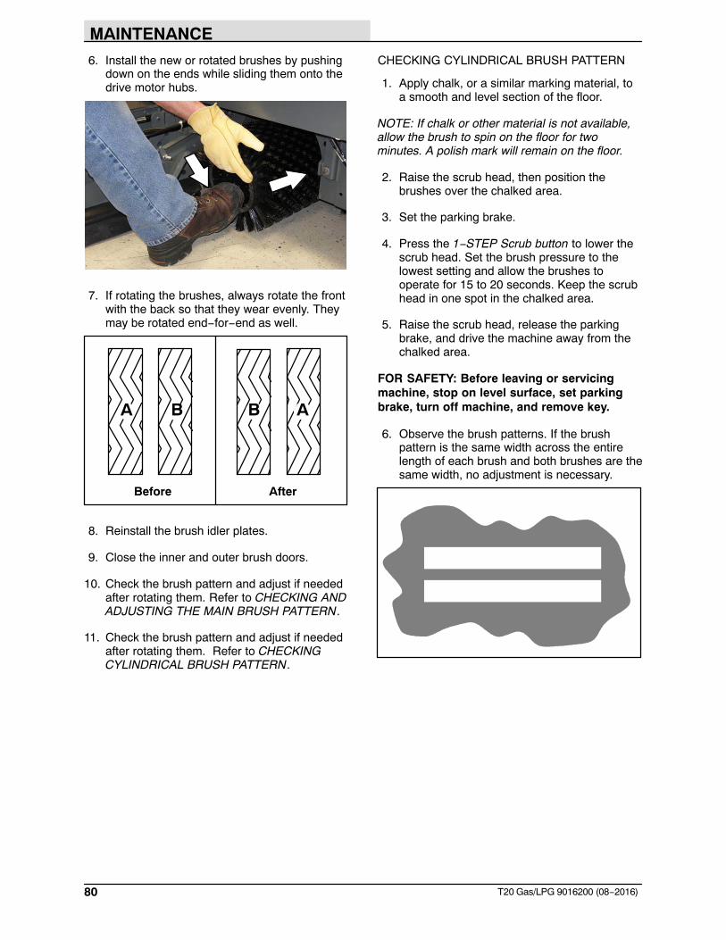
MAINTENANCE
80 T20 Gas/LPG 9016200 (08−2016)
6. Install the new or rotated brushes by pushingdown on the ends while sliding them onto thedrive motor hubs.
7. If rotating the brushes, always rotate the frontwith the back so that they wear evenly. Theymay be rotated end−for−end as well.
Before After
A B B A
8. Reinstall the brush idler plates.
9. Close the inner and outer brush doors.
10. Check the brush pattern and adjust if neededafter rotating them. Refer to CHECKING ANDADJUSTING THE MAIN BRUSH PATTERN.
11. Check the brush pattern and adjust if neededafter rotating them. Refer to CHECKINGCYLINDRICAL BRUSH PATTERN.
CHECKING CYLINDRICAL BRUSH PATTERN
1. Apply chalk, or a similar marking material, toa smooth and level section of the floor.
NOTE: If chalk or other material is not available,allow the brush to spin on the floor for twominutes. A polish mark will remain on the floor.
2. Raise the scrub head, then position thebrushes over the chalked area.
3. Set the parking brake.
4. Press the 1−STEP Scrub button to lower thescrub head. Set the brush pressure to thelowest setting and allow the brushes tooperate for 15 to 20 seconds. Keep the scrubhead in one spot in the chalked area.
5. Raise the scrub head, release the parkingbrake, and drive the machine away from thechalked area.
FOR SAFETY: Before leaving or servicingmachine, stop on level surface, set parkingbrake, turn off machine, and remove key.
6. Observe the brush patterns. If the brushpattern is the same width across the entirelength of each brush and both brushes are thesame width, no adjustment is necessary.
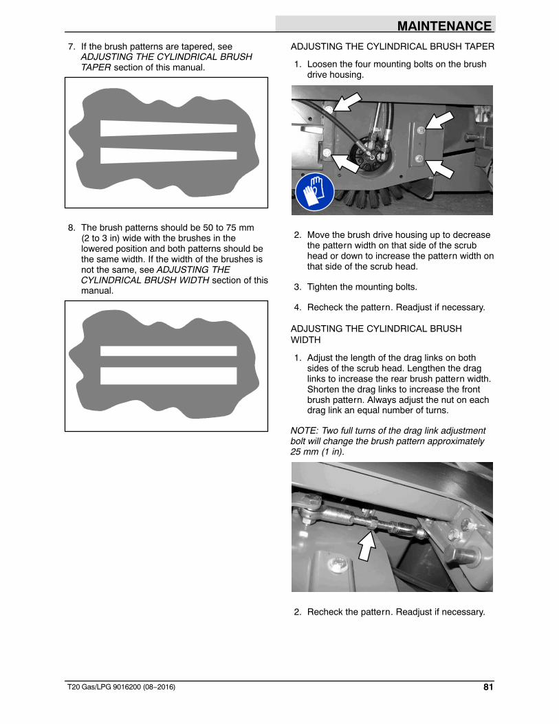
MAINTENANCE
81T20 Gas/LPG 9016200 (08−2016)
7. If the brush patterns are tapered, seeADJUSTING THE CYLINDRICAL BRUSHTAPER section of this manual.
8. The brush patterns should be 50 to 75 mm (2 to 3 in) wide with the brushes in thelowered position and both patterns should bethe same width. If the width of the brushes isnot the same, see ADJUSTING THECYLINDRICAL BRUSH WIDTH section of thismanual.
ADJUSTING THE CYLINDRICAL BRUSH TAPER
1. Loosen the four mounting bolts on the brushdrive housing.
2. Move the brush drive housing up to decreasethe pattern width on that side of the scrubhead or down to increase the pattern width onthat side of the scrub head.
3. Tighten the mounting bolts.
4. Recheck the pattern. Readjust if necessary.
ADJUSTING THE CYLINDRICAL BRUSHWIDTH
1. Adjust the length of the drag links on bothsides of the scrub head. Lengthen the draglinks to increase the rear brush pattern width.Shorten the drag links to increase the frontbrush pattern. Always adjust the nut on eachdrag link an equal number of turns.
NOTE: Two full turns of the drag link adjustmentbolt will change the brush pattern approximately25 mm (1 in).
2. Recheck the pattern. Readjust if necessary.
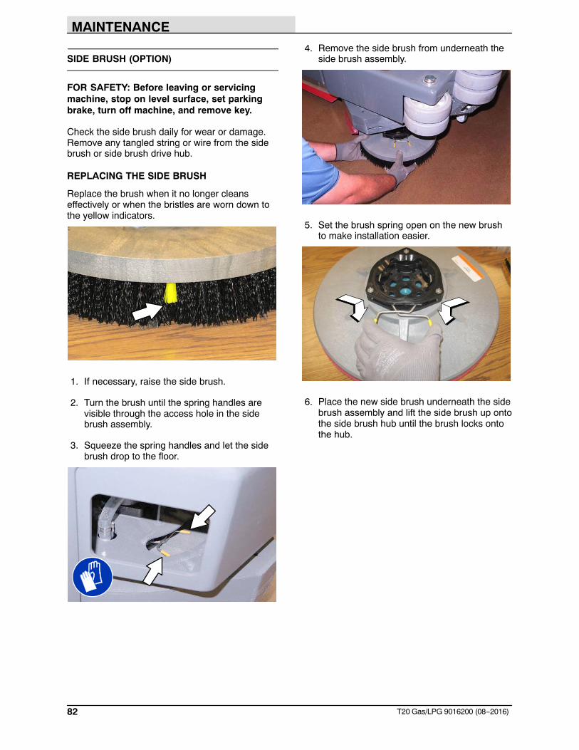
MAINTENANCE
82 T20 Gas/LPG 9016200 (08−2016)
SIDE BRUSH (OPTION)
FOR SAFETY: Before leaving or servicingmachine, stop on level surface, set parkingbrake, turn off machine, and remove key.
Check the side brush daily for wear or damage.Remove any tangled string or wire from the sidebrush or side brush drive hub.
REPLACING THE SIDE BRUSH
Replace the brush when it no longer cleanseffectively or when the bristles are worn down tothe yellow indicators.
1. If necessary, raise the side brush.
2. Turn the brush until the spring handles arevisible through the access hole in the sidebrush assembly.
3. Squeeze the spring handles and let the sidebrush drop to the floor.
4. Remove the side brush from underneath theside brush assembly.
5. Set the brush spring open on the new brushto make installation easier.
6. Place the new side brush underneath the sidebrush assembly and lift the side brush up ontothe side brush hub until the brush locks ontothe hub.
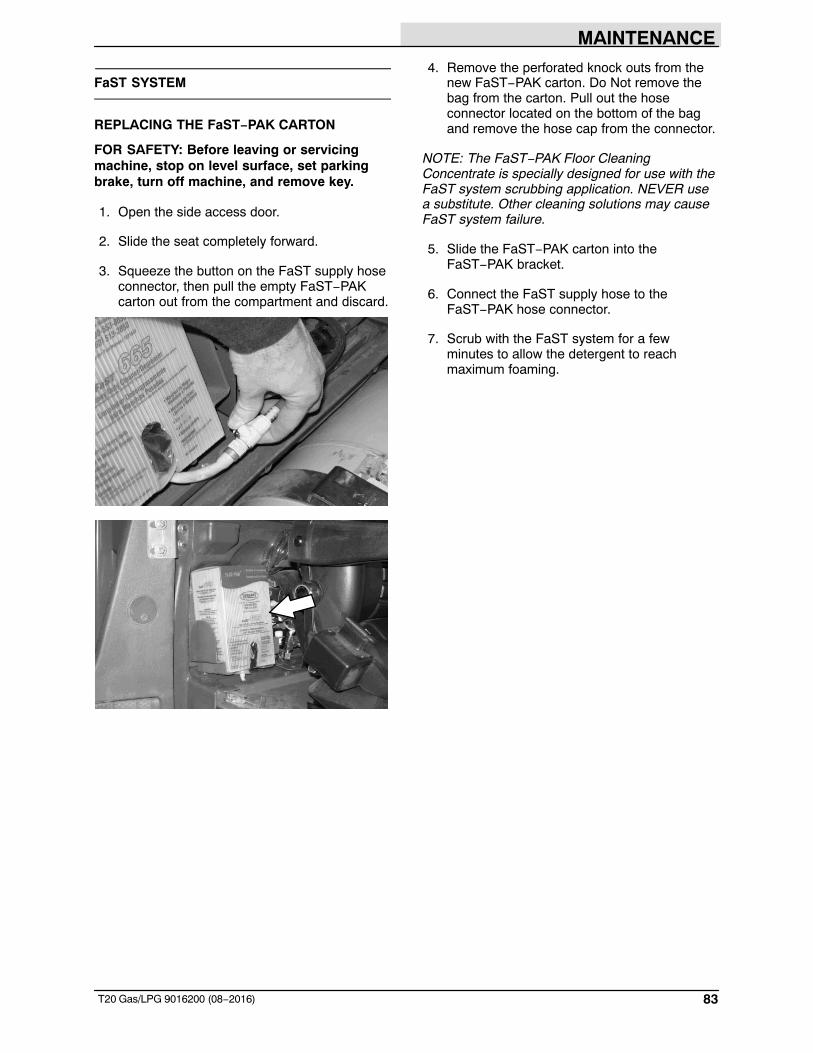
MAINTENANCE
83T20 Gas/LPG 9016200 (08−2016)
FaST SYSTEM
REPLACING THE FaST−PAK CARTON
FOR SAFETY: Before leaving or servicingmachine, stop on level surface, set parkingbrake, turn off machine, and remove key.
1. Open the side access door.
2. Slide the seat completely forward.
3. Squeeze the button on the FaST supply hoseconnector, then pull the empty FaST−PAKcarton out from the compartment and discard.
4. Remove the perforated knock outs from thenew FaST−PAK carton. Do Not remove thebag from the carton. Pull out the hoseconnector located on the bottom of the bagand remove the hose cap from the connector.
NOTE: The FaST−PAK Floor CleaningConcentrate is specially designed for use with theFaST system scrubbing application. NEVER usea substitute. Other cleaning solutions may causeFaST system failure.
5. Slide the FaST−PAK carton into theFaST−PAK bracket.
6. Connect the FaST supply hose to theFaST−PAK hose connector.
7. Scrub with the FaST system for a fewminutes to allow the detergent to reachmaximum foaming.
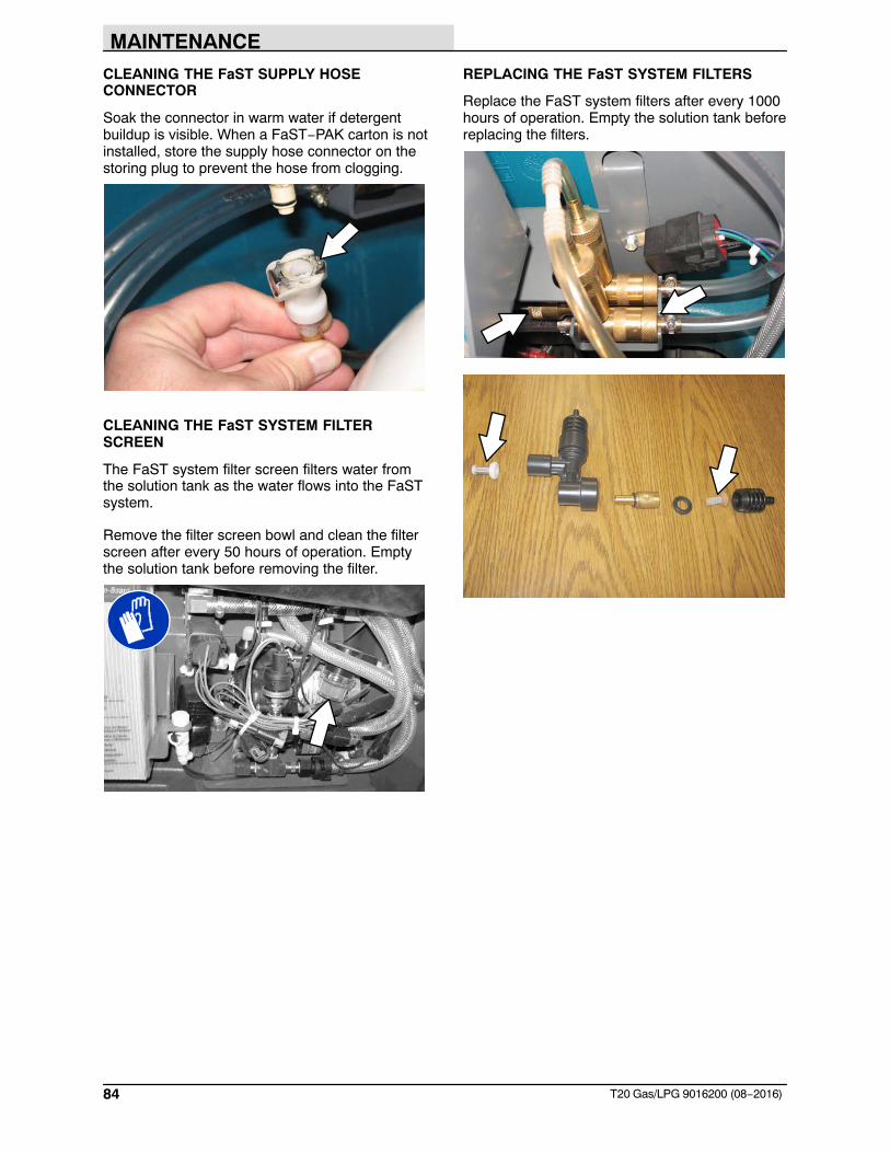
MAINTENANCE
84 T20 Gas/LPG 9016200 (08−2016)
CLEANING THE FaST SUPPLY HOSECONNECTOR
Soak the connector in warm water if detergentbuildup is visible. When a FaST−PAK carton is notinstalled, store the supply hose connector on thestoring plug to prevent the hose from clogging.
CLEANING THE FaST SYSTEM FILTERSCREEN
The FaST system filter screen filters water fromthe solution tank as the water flows into the FaSTsystem.
Remove the filter screen bowl and clean the filterscreen after every 50 hours of operation. Emptythe solution tank before removing the filter.
REPLACING THE FaST SYSTEM FILTERS
Replace the FaST system filters after every 1000hours of operation. Empty the solution tank beforereplacing the filters.
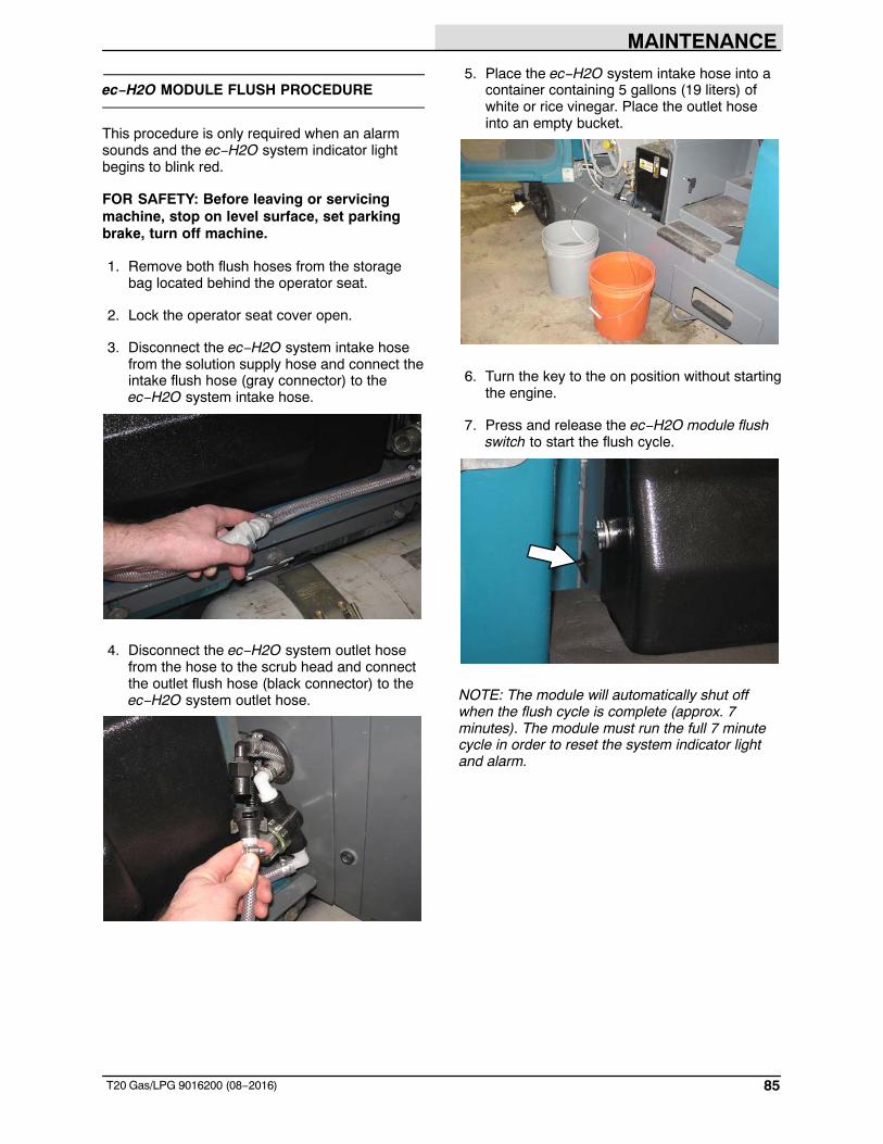
MAINTENANCE
85T20 Gas/LPG 9016200 (08−2016)
ec−H2O MODULE FLUSH PROCEDURE
This procedure is only required when an alarmsounds and the ec−H2O system indicator lightbegins to blink red.
FOR SAFETY: Before leaving or servicingmachine, stop on level surface, set parkingbrake, turn off machine.
1. Remove both flush hoses from the storagebag located behind the operator seat.
2. Lock the operator seat cover open.
3. Disconnect the ec−H2O system intake hosefrom the solution supply hose and connect theintake flush hose (gray connector) to theec−H2O system intake hose.
4. Disconnect the ec−H2O system outlet hosefrom the hose to the scrub head and connectthe outlet flush hose (black connector) to theec−H2O system outlet hose.
5. Place the ec−H2O system intake hose into acontainer containing 5 gallons (19 liters) ofwhite or rice vinegar. Place the outlet hoseinto an empty bucket.
6. Turn the key to the on position without startingthe engine.
7. Press and release the ec−H2O module flushswitch to start the flush cycle.
NOTE: The module will automatically shut offwhen the flush cycle is complete (approx. 7minutes). The module must run the full 7 minutecycle in order to reset the system indicator lightand alarm.
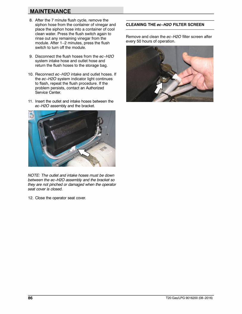
MAINTENANCE
86 T20 Gas/LPG 9016200 (08−2016)
8. After the 7 minute flush cycle, remove thesiphon hose from the container of vinegar andplace the siphon hose into a container of coolclean water. Press the flush switch again torinse out any remaining vinegar from themodule. After 1−2 minutes, press the flushswitch to turn off the module.
9. Disconnect the flush hoses from the ec−H2Osystem intake hose and outlet hose andreturn the flush hoses to the storage bag.
10. Reconnect ec−H2O intake and outlet hoses. Ifthe ec−H2O system indicator light continuesto flash, repeat the flush procedure. If theproblem persists, contact an AuthorizedService Center.
11. Insert the outlet and intake hoses between theec−H2O assembly and the bracket.
NOTE: The outlet and intake hoses must be downbetween the ec−H2O assembly and the bracket sothey are not pinched or damaged when the operatorseat cover is closed.
12. Close the operator seat cover.
CLEANING THE ec−H2O FILTER SCREEN
Remove and clean the ec−H2O filter screen afterevery 50 hours of operation.
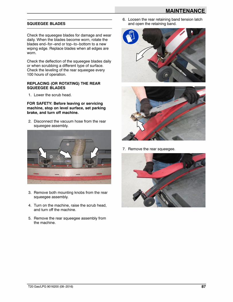
MAINTENANCE
87T20 Gas/LPG 9016200 (08−2016)
SQUEEGEE BLADES
Check the squeegee blades for damage and weardaily. When the blades become worn, rotate theblades end−for−end or top−to−bottom to a newwiping edge. Replace blades when all edges areworn.
Check the deflection of the squeegee blades dailyor when scrubbing a different type of surface.Check the leveling of the rear squeegee every100 hours of operation.
REPLACING (OR ROTATING) THE REARSQUEEGEE BLADES
1. Lower the scrub head.
FOR SAFETY: Before leaving or servicingmachine, stop on level surface, set parkingbrake, and turn off machine.
2. Disconnect the vacuum hose from the rearsqueegee assembly.
3. Remove both mounting knobs from the rearsqueegee assembly.
4. Turn on the machine, raise the scrub head,and turn off the machine.
5. Remove the rear squeegee assembly fromthe machine.
6. Loosen the rear retaining band tension latchand open the retaining band.
7. Remove the rear squeegee.
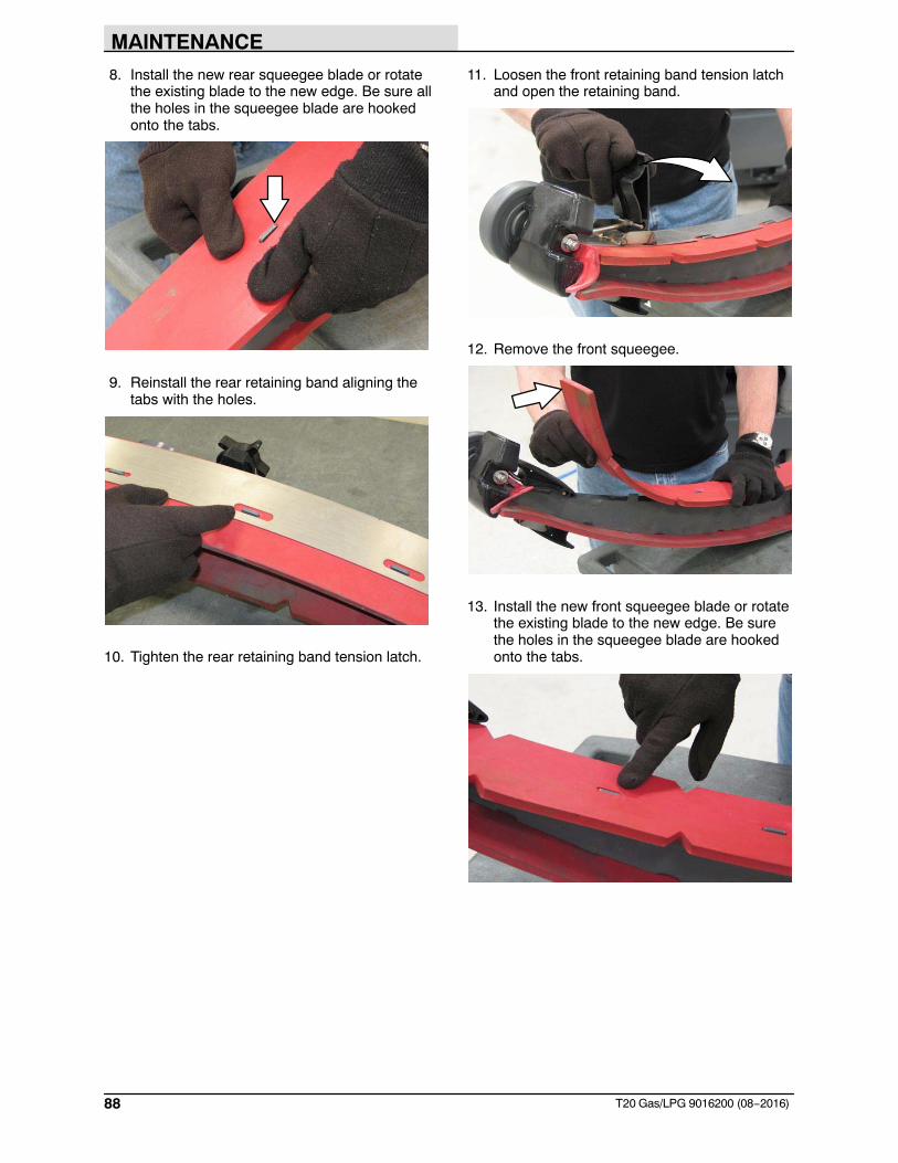
MAINTENANCE
88 T20 Gas/LPG 9016200 (08−2016)
8. Install the new rear squeegee blade or rotatethe existing blade to the new edge. Be sure allthe holes in the squeegee blade are hookedonto the tabs.
9. Reinstall the rear retaining band aligning thetabs with the holes.
10. Tighten the rear retaining band tension latch.
11. Loosen the front retaining band tension latchand open the retaining band.
12. Remove the front squeegee.
13. Install the new front squeegee blade or rotatethe existing blade to the new edge. Be surethe holes in the squeegee blade are hookedonto the tabs.
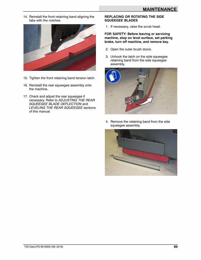
MAINTENANCE
89T20 Gas/LPG 9016200 (08−2016)
14. Reinstall the front retaining band aligning thetabs with the notches.
15. Tighten the front retaining band tension latch.
16. Reinstall the rear squeegee assembly ontothe machine.
17. Check and adjust the rear squeegee ifnecessary. Refer to ADJUSTING THE REARSQUEEGEE BLADE DEFLECTION andLEVELING THE REAR SQUEEGEE sectionsof this manual.
REPLACING OR ROTATING THE SIDESQUEEGEE BLADES
1. If necessary, raise the scrub head.
FOR SAFETY: Before leaving or servicingmachine, stop on level surface, set parkingbrake, turn off machine, and remove key.
2. Open the outer brush doors.
3. Unhook the latch on the side squeegeeretaining band from the side squeegeeassembly.
4. Remove the retaining band from the sidesqueegee assembly.
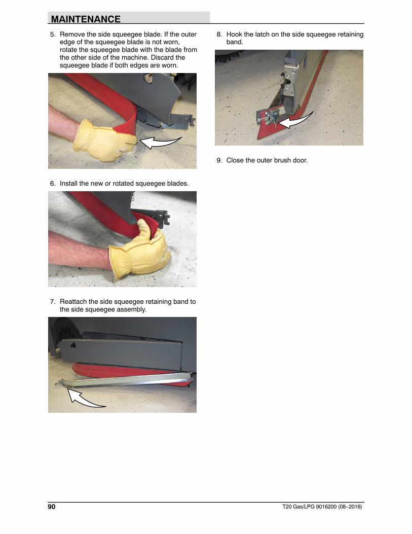
MAINTENANCE
90 T20 Gas/LPG 9016200 (08−2016)
5. Remove the side squeegee blade. If the outeredge of the squeegee blade is not worn,rotate the squeegee blade with the blade fromthe other side of the machine. Discard thesqueegee blade if both edges are worn.
6. Install the new or rotated squeegee blades.
7. Reattach the side squeegee retaining band tothe side squeegee assembly.
8. Hook the latch on the side squeegee retainingband.
9. Close the outer brush door.
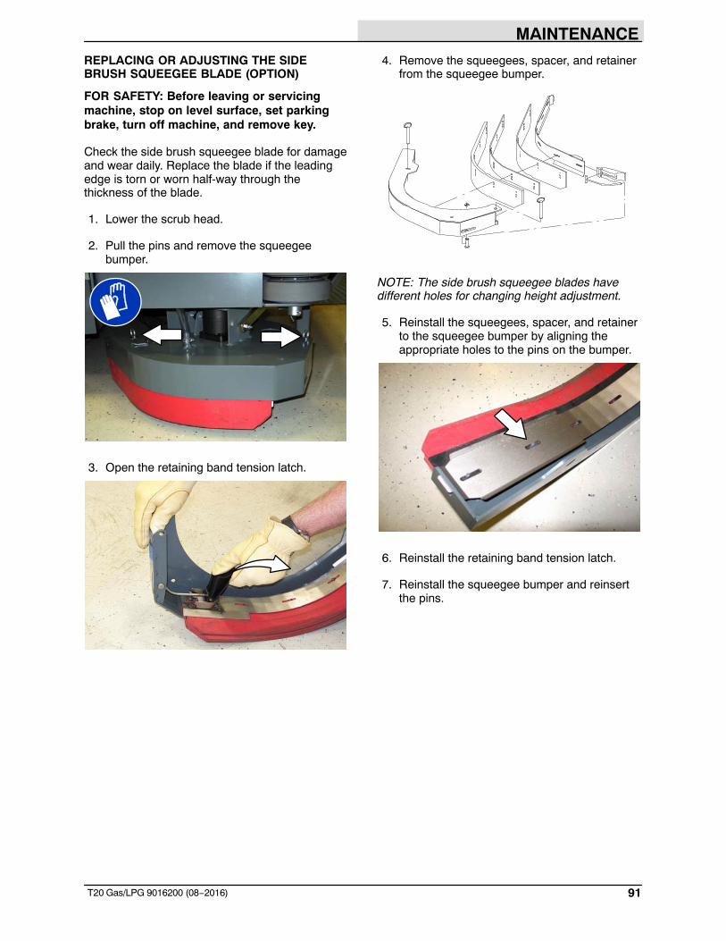
MAINTENANCE
91T20 Gas/LPG 9016200 (08−2016)
REPLACING OR ADJUSTING THE SIDEBRUSH SQUEEGEE BLADE (OPTION)
FOR SAFETY: Before leaving or servicingmachine, stop on level surface, set parkingbrake, turn off machine, and remove key.
Check the side brush squeegee blade for damageand wear daily. Replace the blade if the leadingedge is torn or worn half-way through thethickness of the blade.
1. Lower the scrub head.
2. Pull the pins and remove the squeegeebumper.
3. Open the retaining band tension latch.
4. Remove the squeegees, spacer, and retainerfrom the squeegee bumper.
NOTE: The side brush squeegee blades havedifferent holes for changing height adjustment.
5. Reinstall the squeegees, spacer, and retainerto the squeegee bumper by aligning theappropriate holes to the pins on the bumper.
6. Reinstall the retaining band tension latch.
7. Reinstall the squeegee bumper and reinsertthe pins.
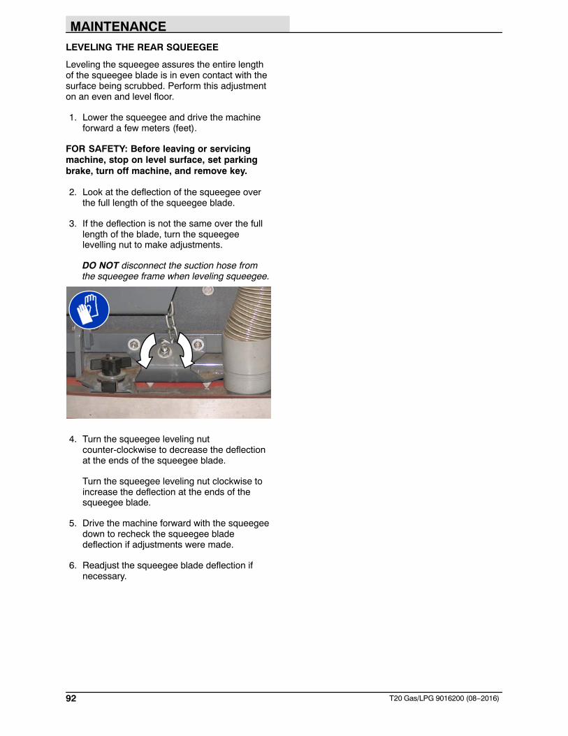
MAINTENANCE
92 T20 Gas/LPG 9016200 (08−2016)
LEVELING THE REAR SQUEEGEE
Leveling the squeegee assures the entire lengthof the squeegee blade is in even contact with thesurface being scrubbed. Perform this adjustmenton an even and level floor.
1. Lower the squeegee and drive the machineforward a few meters (feet).
FOR SAFETY: Before leaving or servicingmachine, stop on level surface, set parkingbrake, turn off machine, and remove key.
2. Look at the deflection of the squeegee overthe full length of the squeegee blade.
3. If the deflection is not the same over the fulllength of the blade, turn the squeegeelevelling nut to make adjustments.
DO NOT disconnect the suction hose fromthe squeegee frame when leveling squeegee.
4. Turn the squeegee leveling nutcounter-clockwise to decrease the deflectionat the ends of the squeegee blade.
Turn the squeegee leveling nut clockwise toincrease the deflection at the ends of thesqueegee blade.
5. Drive the machine forward with the squeegeedown to recheck the squeegee bladedeflection if adjustments were made.
6. Readjust the squeegee blade deflection ifnecessary.
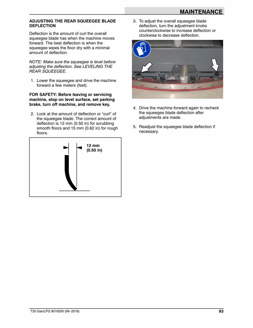
MAINTENANCE
93T20 Gas/LPG 9016200 (08−2016)
ADJUSTING THE REAR SQUEEGEE BLADEDEFLECTION
Deflection is the amount of curl the overallsqueegee blade has when the machine movesforward. The best deflection is when thesqueegee wipes the floor dry with a minimalamount of deflection.
NOTE: Make sure the squeegee is level beforeadjusting the deflection. See LEVELING THEREAR SQUEEGEE.
1. Lower the squeegee and drive the machineforward a few meters (feet).
FOR SAFETY: Before leaving or servicingmachine, stop on level surface, set parkingbrake, turn off machine, and remove key.
2. Look at the amount of deflection or “curl” ofthe squeegee blade. The correct amount ofdeflection is 12 mm (0.50 in) for scrubbingsmooth floors and 15 mm (0.62 in) for roughfloors.
12 mm(0.50 in)
3. To adjust the overall squeegee bladedeflection, turn the adjustment knobscounterclockwise to increase deflection orclockwise to decrease deflection.
4. Drive the machine forward again to recheckthe squeegee blade deflection afteradjustments are made.
5. Readjust the squeegee blade deflection ifnecessary.
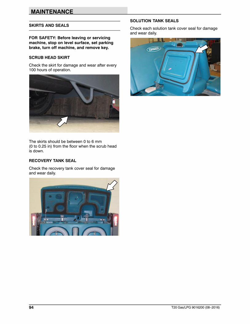
MAINTENANCE
94 T20 Gas/LPG 9016200 (08−2016)
SKIRTS AND SEALS
FOR SAFETY: Before leaving or servicingmachine, stop on level surface, set parkingbrake, turn off machine, and remove key.
SCRUB HEAD SKIRT
Check the skirt for damage and wear after every100 hours of operation.
The skirts should be between 0 to 6 mm(0 to 0.25 in) from the floor when the scrub headis down.
RECOVERY TANK SEAL
Check the recovery tank cover seal for damageand wear daily.
SOLUTION TANK SEALS
Check each solution tank cover seal for damageand wear daily.
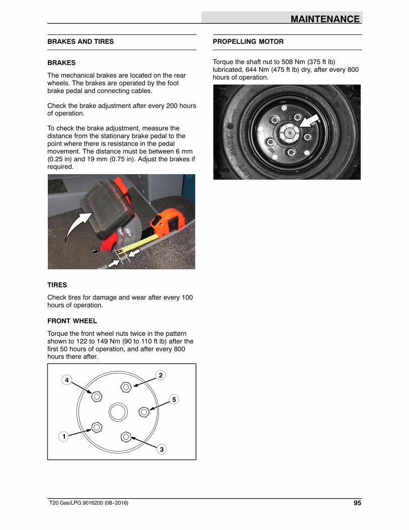
MAINTENANCE
95T20 Gas/LPG 9016200 (08−2016)
BRAKES AND TIRES
BRAKES
The mechanical brakes are located on the rearwheels. The brakes are operated by the footbrake pedal and connecting cables.
Check the brake adjustment after every 200 hoursof operation.
To check the brake adjustment, measure thedistance from the stationary brake pedal to thepoint where there is resistance in the pedalmovement. The distance must be between 6 mm(0.25 in) and 19 mm (0.75 in). Adjust the brakes ifrequired.
TIRES
Check tires for damage and wear after every 100hours of operation.
FRONT WHEEL
Torque the front wheel nuts twice in the patternshown to 122 to 149 Nm (90 to 110 ft lb) after thefirst 50 hours of operation, and after every 800hours there after.
2
3
4
1
5
PROPELLING MOTOR
Torque the shaft nut to 508 Nm (375 ft lb)lubricated, 644 Nm (475 ft lb) dry, after every 800hours of operation.
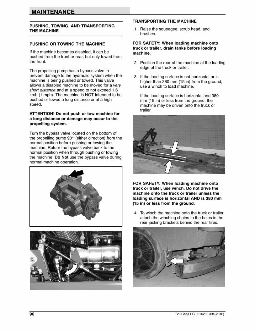
MAINTENANCE
96 T20 Gas/LPG 9016200 (08−2016)
PUSHING, TOWING, AND TRANSPORTINGTHE MACHINE
PUSHING OR TOWING THE MACHINE
If the machine becomes disabled, it can bepushed from the front or rear, but only towed fromthe front.
The propelling pump has a bypass valve toprevent damage to the hydraulic system when themachine is being pushed or towed. This valveallows a disabled machine to be moved for a veryshort distance and at a speed to not exceed 1.6kp/h (1 mph). The machine is NOT intended to bepushed or towed a long distance or at a highspeed.
ATTENTION! Do not push or tow machine fora long distance or damage may occur to thepropelling system.
Turn the bypass valve located on the bottom ofthe propelling pump 90� (either direction) from thenormal position before pushing or towing themachine. Return the bypass valve back to thenormal position when through pushing or towingthe machine. Do Not use the bypass valve duringnormal machine operation.
TRANSPORTING THE MACHINE
1. Raise the squeegee, scrub head, andbrushes.
FOR SAFETY: When loading machine ontotruck or trailer, drain tanks before loadingmachine.
2. Position the rear of the machine at the loadingedge of the truck or trailer.
3. If the loading surface is not horizontal or ishigher than 380 mm (15 in) from the ground,use a winch to load machine.
If the loading surface is horizontal and 380mm (15 in) or less from the ground, themachine may be driven onto the truck ortrailer.
FOR SAFETY: When loading machine ontotruck or trailer, use winch. Do not drive themachine onto the truck or trailer unless theloading surface is horizontal AND is 380 mm(15 in) or less from the ground.
4. To winch the machine onto the truck or trailer,attach the winching chains to the holes in therear jacking brackets behind the rear tires.
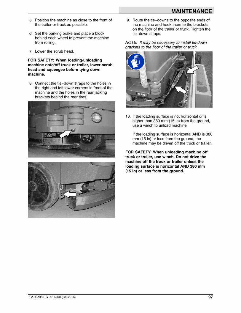
MAINTENANCE
97T20 Gas/LPG 9016200 (08−2016)
5. Position the machine as close to the front ofthe trailer or truck as possible.
6. Set the parking brake and place a blockbehind each wheel to prevent the machinefrom rolling.
7. Lower the scrub head.
FOR SAFETY: When loading/unloadingmachine onto/off truck or trailer, lower scrubhead and squeegee before tying downmachine.
8. Connect the tie−down straps to the holes inthe right and left lower corners in front of themachine and the holes in the rear jackingbrackets behind the rear tires.
9. Route the tie−downs to the opposite ends ofthe machine and hook them to the bracketson the floor of the trailer or truck. Tighten thetie−down straps.
NOTE: It may be necessary to install tie-downbrackets to the floor of the trailer or truck.
10. If the loading surface is not horizontal or ishigher than 380 mm (15 in) from the ground,use a winch to unload machine.
If the loading surface is horizontal AND is 380mm (15 in) or less from the ground, themachine may be driven off the truck or trailer.
FOR SAFETY: When unloading machine offtruck or trailer, use winch. Do not drive themachine off the truck or trailer unless theloading surface is horizontal AND 380 mm (15 in) or less from the ground.
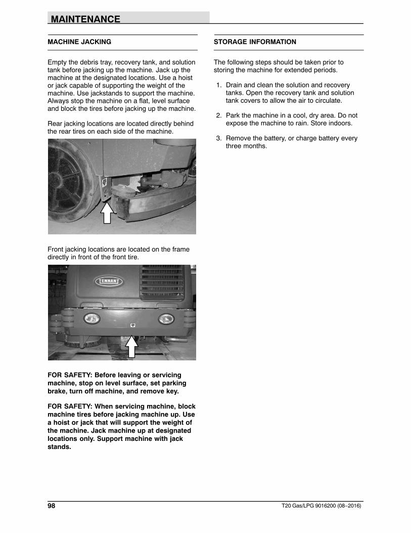
MAINTENANCE
98 T20 Gas/LPG 9016200 (08−2016)
MACHINE JACKING
Empty the debris tray, recovery tank, and solutiontank before jacking up the machine. Jack up themachine at the designated locations. Use a hoistor jack capable of supporting the weight of themachine. Use jackstands to support the machine.Always stop the machine on a flat, level surfaceand block the tires before jacking up the machine.
Rear jacking locations are located directly behindthe rear tires on each side of the machine.
Front jacking locations are located on the framedirectly in front of the front tire.
FOR SAFETY: Before leaving or servicingmachine, stop on level surface, set parkingbrake, turn off machine, and remove key.
FOR SAFETY: When servicing machine, blockmachine tires before jacking machine up. Usea hoist or jack that will support the weight ofthe machine. Jack machine up at designatedlocations only. Support machine with jackstands.
STORAGE INFORMATION
The following steps should be taken prior tostoring the machine for extended periods.
1. Drain and clean the solution and recoverytanks. Open the recovery tank and solutiontank covers to allow the air to circulate.
2. Park the machine in a cool, dry area. Do notexpose the machine to rain. Store indoors.
3. Remove the battery, or charge battery everythree months.
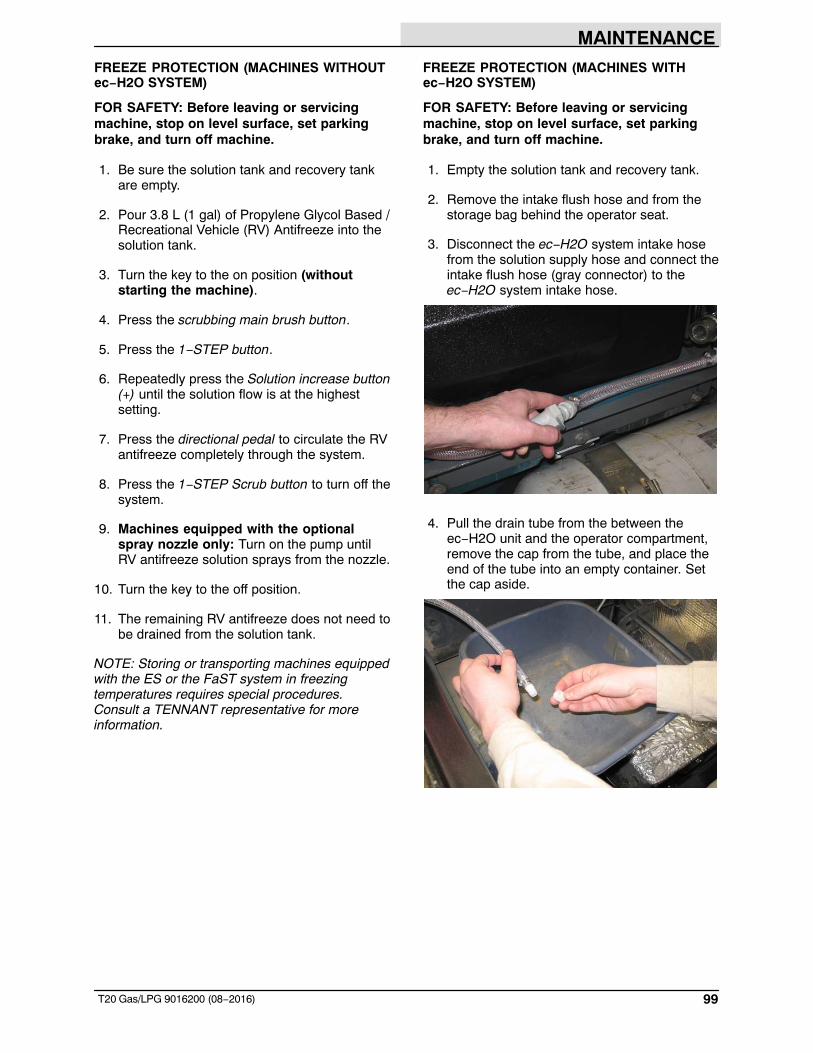
MAINTENANCE
99T20 Gas/LPG 9016200 (08−2016)
FREEZE PROTECTION (MACHINES WITHOUTec−H2O SYSTEM)
FOR SAFETY: Before leaving or servicingmachine, stop on level surface, set parkingbrake, and turn off machine.
1. Be sure the solution tank and recovery tankare empty.
2. Pour 3.8 L (1 gal) of Propylene Glycol Based /Recreational Vehicle (RV) Antifreeze into thesolution tank.
3. Turn the key to the on position (withoutstarting the machine).
4. Press the scrubbing main brush button.
5. Press the 1−STEP button.
6. Repeatedly press the Solution increase button(+) until the solution flow is at the highestsetting.
7. Press the directional pedal to circulate the RVantifreeze completely through the system.
8. Press the 1−STEP Scrub button to turn off thesystem.
9. Machines equipped with the optionalspray nozzle only: Turn on the pump untilRV antifreeze solution sprays from the nozzle.
10. Turn the key to the off position.
11. The remaining RV antifreeze does not need tobe drained from the solution tank.
NOTE: Storing or transporting machines equippedwith the ES or the FaST system in freezingtemperatures requires special procedures.Consult a TENNANT representative for moreinformation.
FREEZE PROTECTION (MACHINES WITHec−H2O SYSTEM)
FOR SAFETY: Before leaving or servicingmachine, stop on level surface, set parkingbrake, and turn off machine.
1. Empty the solution tank and recovery tank.
2. Remove the intake flush hose and from thestorage bag behind the operator seat.
3. Disconnect the ec−H2O system intake hosefrom the solution supply hose and connect theintake flush hose (gray connector) to theec−H2O system intake hose.
4. Pull the drain tube from the between theec−H2O unit and the operator compartment,remove the cap from the tube, and place theend of the tube into an empty container. Setthe cap aside.
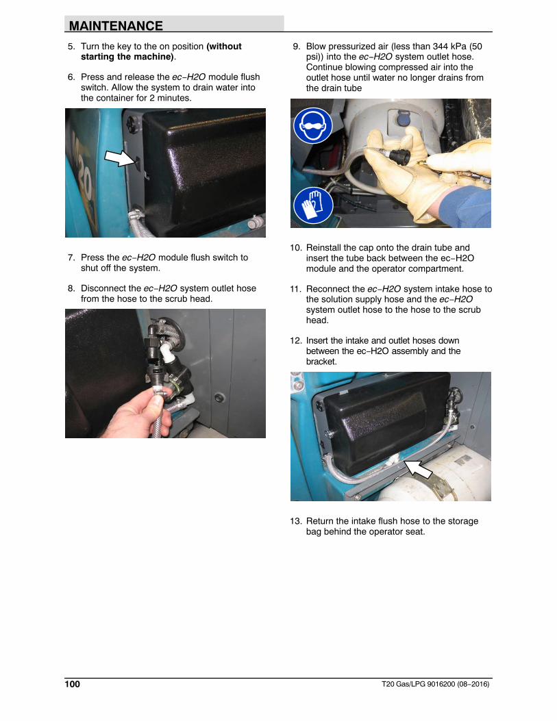
MAINTENANCE
100 T20 Gas/LPG 9016200 (08−2016)
5. Turn the key to the on position (withoutstarting the machine).
6. Press and release the ec−H2O module flushswitch. Allow the system to drain water intothe container for 2 minutes.
7. Press the ec−H2O module flush switch toshut off the system.
8. Disconnect the ec−H2O system outlet hosefrom the hose to the scrub head.
9. Blow pressurized air (less than 344 kPa (50psi)) into the ec−H2O system outlet hose.Continue blowing compressed air into theoutlet hose until water no longer drains fromthe drain tube
10. Reinstall the cap onto the drain tube andinsert the tube back between the ec−H2Omodule and the operator compartment.
11. Reconnect the ec−H2O system intake hose tothe solution supply hose and the ec−H2Osystem outlet hose to the hose to the scrubhead.
12. Insert the intake and outlet hoses downbetween the ec−H2O assembly and thebracket.
13. Return the intake flush hose to the storagebag behind the operator seat.
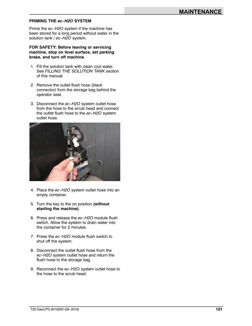
MAINTENANCE
101T20 Gas/LPG 9016200 (08−2016)
PRIMING THE ec−H2O SYSTEM
Prime the ec−H2O system if the machine hasbeen stored for a long period without water in thesolution tank / ec−H2O system.
FOR SAFETY: Before leaving or servicingmachine, stop on level surface, set parkingbrake, and turn off machine.
1. Fill the solution tank with clean cool water.See FILLING THE SOLUTION TANK sectionof this manual.
2. Remove the outlet flush hose (blackconnector) from the storage bag behind theoperator seat.
3. Disconnect the ec−H2O system outlet hosefrom the hose to the scrub head and connectthe outlet flush hose to the ec−H2O systemoutlet hose.
4. Place the ec−H2O system outlet hose into anempty container.
5. Turn the key to the on position (withoutstarting the machine).
6. Press and release the ec−H2O module flushswitch. Allow the system to drain water intothe container for 2 minutes.
7. Press the ec−H2O module flush switch toshut off the system.
8. Disconnect the outlet flush hose from theec−H2O system outlet hose and return theflush hose to the storage bag.
9. Reconnect the ec−H2O system outlet hose tothe hose to the scrub head.
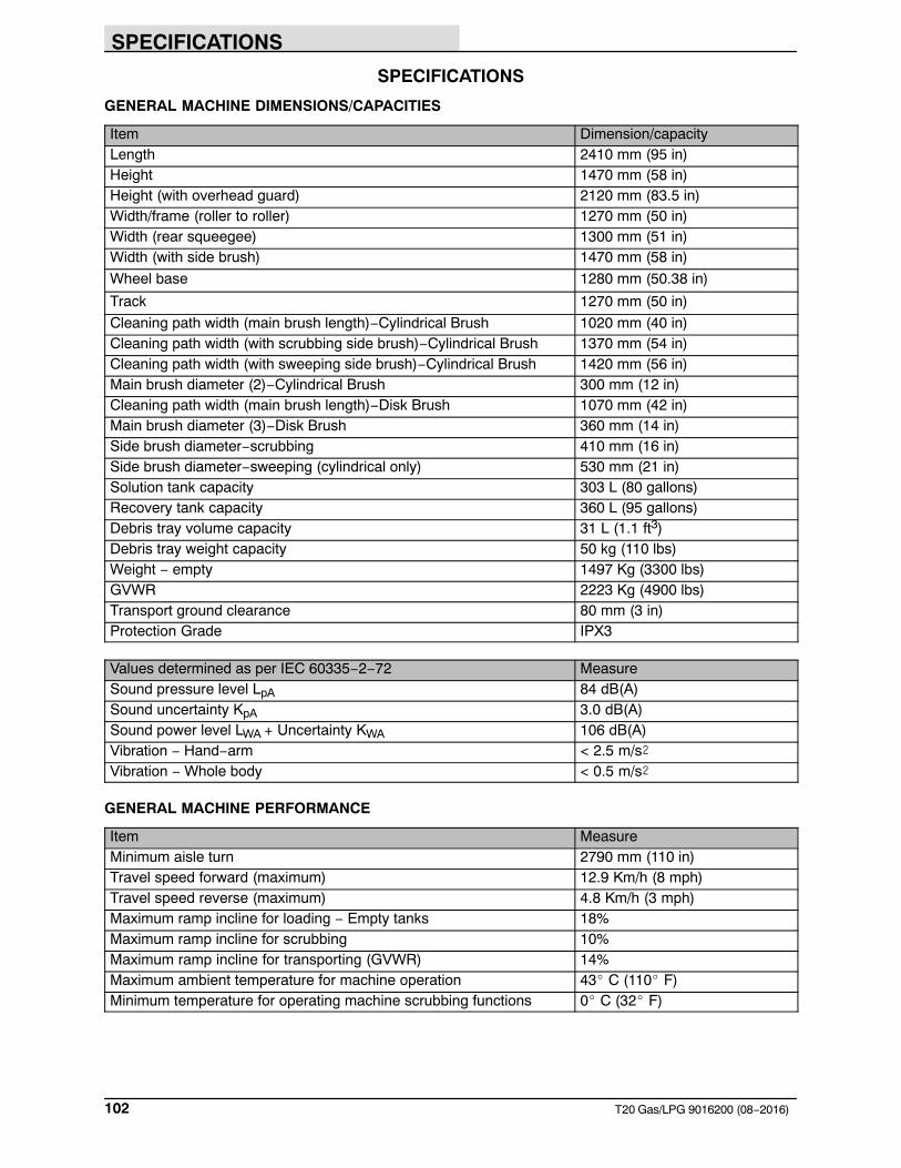
SPECIFICATIONS
102 T20 Gas/LPG 9016200 (08−2016)
SPECIFICATIONS
GENERAL MACHINE DIMENSIONS/CAPACITIES
Item Dimension/capacityLength 2410 mm (95 in)Height 1470 mm (58 in)Height (with overhead guard) 2120 mm (83.5 in)Width/frame (roller to roller) 1270 mm (50 in)Width (rear squeegee) 1300 mm (51 in)Width (with side brush) 1470 mm (58 in)
Wheel base 1280 mm (50.38 in)
Track 1270 mm (50 in)
Cleaning path width (main brush length)−Cylindrical Brush 1020 mm (40 in)Cleaning path width (with scrubbing side brush)−Cylindrical Brush 1370 mm (54 in)Cleaning path width (with sweeping side brush)−Cylindrical Brush 1420 mm (56 in)Main brush diameter (2)−Cylindrical Brush 300 mm (12 in)Cleaning path width (main brush length)−Disk Brush 1070 mm (42 in)Main brush diameter (3)−Disk Brush 360 mm (14 in)Side brush diameter−scrubbing 410 mm (16 in)Side brush diameter−sweeping (cylindrical only) 530 mm (21 in)Solution tank capacity 303 L (80 gallons)Recovery tank capacity 360 L (95 gallons)Debris tray volume capacity 31 L (1.1 ft3)Debris tray weight capacity 50 kg (110 lbs)Weight − empty 1497 Kg (3300 lbs)GVWR 2223 Kg (4900 lbs)Transport ground clearance 80 mm (3 in)Protection Grade IPX3
Values determined as per IEC 60335−2−72 MeasureSound pressure level LpA 84 dB(A)Sound uncertainty KpA 3.0 dB(A)Sound power level LWA + Uncertainty KWA 106 dB(A)Vibration − Hand−arm < 2.5 m/s�Vibration − Whole body < 0.5 m/s�
GENERAL MACHINE PERFORMANCE
Item MeasureMinimum aisle turn 2790 mm (110 in)Travel speed forward (maximum) 12.9 Km/h (8 mph)Travel speed reverse (maximum) 4.8 Km/h (3 mph)Maximum ramp incline for loading − Empty tanks 18%Maximum ramp incline for scrubbing 10%Maximum ramp incline for transporting (GVWR) 14%Maximum ambient temperature for machine operation 43� C (110� F)Minimum temperature for operating machine scrubbing functions 0� C (32� F)
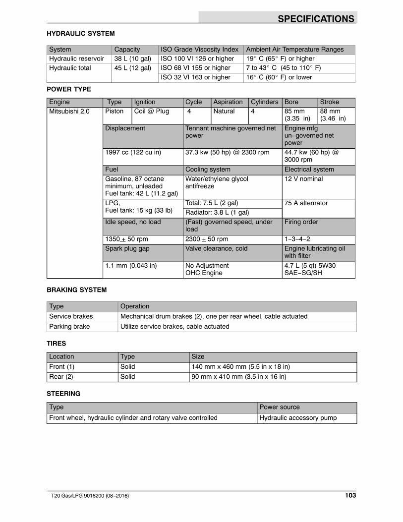
SPECIFICATIONS
103T20 Gas/LPG 9016200 (08−2016)
HYDRAULIC SYSTEM
System Capacity ISO Grade Viscosity Index Ambient Air Temperature RangesHydraulic reservoir 38 L (10 gal) ISO 100 VI 126 or higher 19� C (65� F) or higherHydraulic total 45 L (12 gal) ISO 68 VI 155 or higher 7 to 43� C (45 to 110� F)
ISO 32 VI 163 or higher 16� C (60� F) or lower
POWER TYPE
Engine Type Ignition Cycle Aspiration Cylinders Bore StrokeMitsubishi 2.0 Piston Coil @ Plug 4 Natural 4 85 mm
(3.35 in)88 mm(3.46 in)
Displacement Tennant machine governed netpower
Engine mfgun−governed netpower
1997 cc (122 cu in) 37.3 kw (50 hp) @ 2300 rpm 44.7 kw (60 hp) @ 3000 rpm
Fuel Cooling system Electrical systemGasoline, 87 octaneminimum, unleadedFuel tank: 42 L (11.2 gal)
Water/ethylene glycol antifreeze
12 V nominal
LPG, Fuel tank: 15 kg (33 lb)
Total: 7.5 L (2 gal) 75 A alternatorRadiator: 3.8 L (1 gal)
Idle speed, no load (Fast) governed speed, underload
Firing order
1350 + 50 rpm 2300 + 50 rpm 1−3−4−2Spark plug gap Valve clearance, cold Engine lubricating oil
with filter
1.1 mm (0.043 in) No AdjustmentOHC Engine
4.7 L (5 qt) 5W30SAE−SG/SH
BRAKING SYSTEM
Type Operation
Service brakes Mechanical drum brakes (2), one per rear wheel, cable actuated
Parking brake Utilize service brakes, cable actuated
TIRES
Location Type Size
Front (1) Solid 140 mm x 460 mm (5.5 in x 18 in)
Rear (2) Solid 90 mm x 410 mm (3.5 in x 16 in)
STEERING
Type Power source
Front wheel, hydraulic cylinder and rotary valve controlled Hydraulic accessory pump
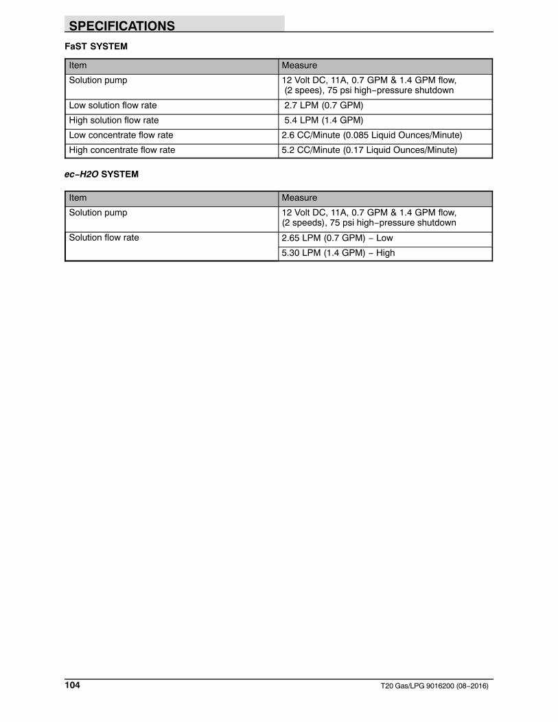
SPECIFICATIONS
104 T20 Gas/LPG 9016200 (08−2016)
FaST SYSTEM
Item Measure
Solution pump 12 Volt DC, 11A, 0.7 GPM & 1.4 GPM flow, (2 spees), 75 psi high−pressure shutdown
Low solution flow rate 2.7 LPM (0.7 GPM)
High solution flow rate 5.4 LPM (1.4 GPM)
Low concentrate flow rate 2.6 CC/Minute (0.085 Liquid Ounces/Minute)
High concentrate flow rate 5.2 CC/Minute (0.17 Liquid Ounces/Minute)
ec−H2O SYSTEM
Item Measure
Solution pump 12 Volt DC, 11A, 0.7 GPM & 1.4 GPM flow, (2 speeds), 75 psi high−pressure shutdown
Solution flow rate 2.65 LPM (0.7 GPM) − Low
5.30 LPM (1.4 GPM) − High
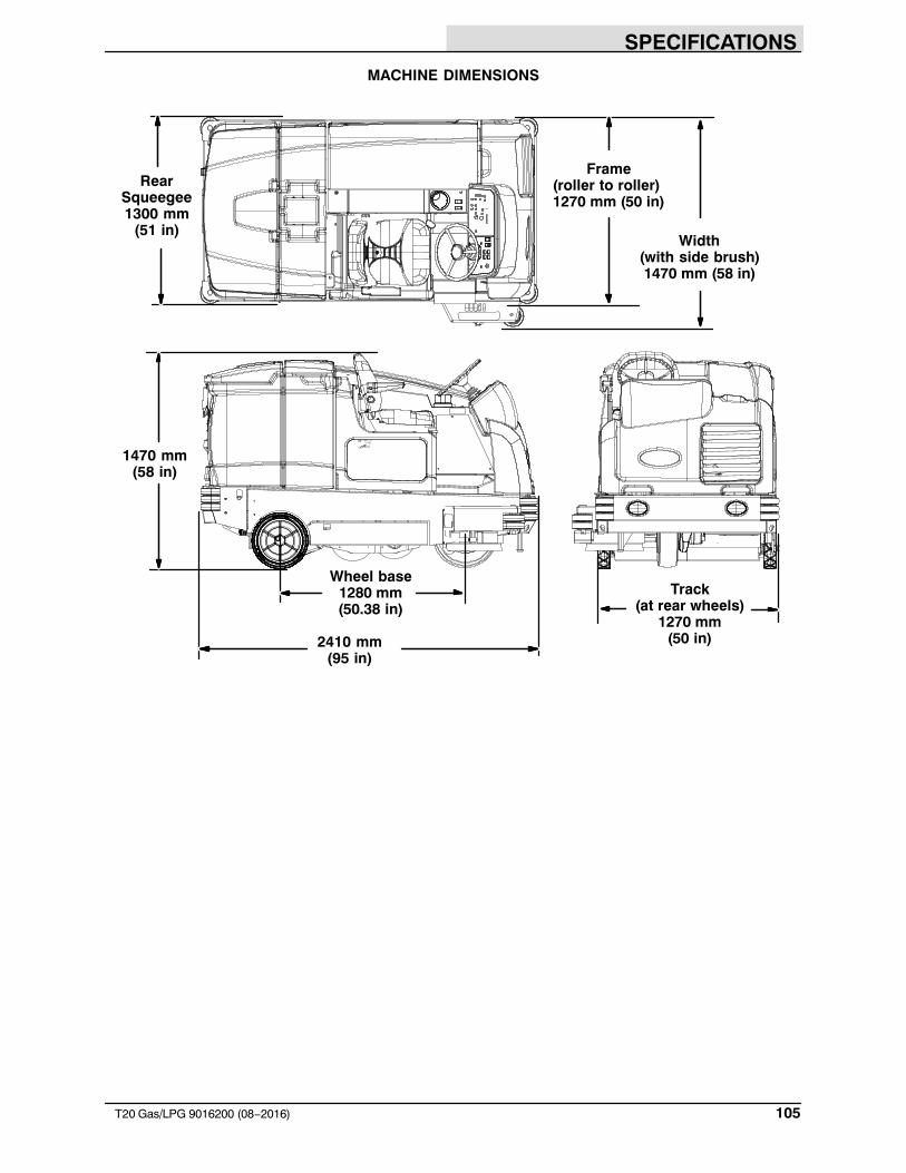
SPECIFICATIONS
105T20 Gas/LPG 9016200 (08−2016)
MACHINE DIMENSIONS
Frame(roller to roller) 1270 mm (50 in)
1470 mm(58 in)
2410 mm(95 in)
RearSqueegee1300 mm
(51 in)Width
(with side brush)1470 mm (58 in)
Wheel base1280 mm(50.38 in)
Track(at rear wheels)
1270 mm(50 in)
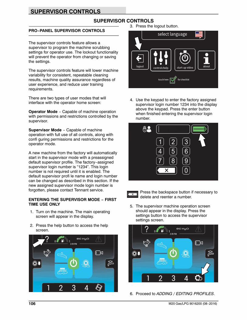
SUPERVISOR CONTROLS
106 M20 Gas/LPG 9016200 (08−2016)
SUPERVISOR CONTROLS
PRO−PANEL SUPERVISOR CONTROLS
The supervisor controls feature allows asupervisor to program the machine scrubbingsettings for operator use. The lockout functionalitywill prevent the operator from changing or savingthe settings.
The supervisor controls feature will lower machinevariability for consistent, repeatable cleaningresults, machine quality assurance regardless ofuser experience, and reduce user trainingrequirements.
There are two types of user modes that willinterface with the operator home screen:
Operator Mode − Capable of machine operationwith permissions and restrictions controlled by thesupervisor.
Supervisor Mode − Capable of machineoperation with full use of all controls, along withconfi guring permissions and restrictions for theoperator mode.
A new machine from the factory will automaticallystart in the supervisor mode with a preassigneddefault supervisor profile. The factory−assignedsupervisor login number is “1234”. This loginnumber is not required until it is enabled. Thedefault supervisor profi le name and login numbercan be changed as described in this section. If thenew assigned supervisor mode login number isforgotten, please contact Tennant service.
ENTERING THE SUPERVISOR MODE − FIRSTTIME USE ONLY
1. Turn on the machine. The main operatingscreen will appear in the display.
2. Press the help button to access the helpscreen.
3. Press the logout button.
4. Use the keypad to enter the factory assignedsupervisor login number 1234 into the displayabove the keypad. Press the enter buttonwhen finished entering the supervisor loginnumber.
Press the backspace button if necessary todelete and reenter a number.
5. The supervisor machine operation screenshould appear in the display. Press thesettings button to access the supervisorsettings screen.
6. Proceed to ADDING / EDITING PROFILES.
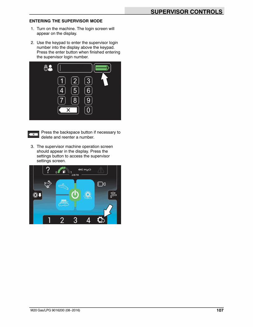
SUPERVISOR CONTROLS
107M20 Gas/LPG 9016200 (08−2016)
ENTERING THE SUPERVISOR MODE
1. Turn on the machine. The login screen willappear on the display.
2. Use the keypad to enter the supervisor loginnumber into the display above the keypad.Press the enter button when finished enteringthe supervisor login number.
Press the backspace button if necessary todelete and reenter a number.
3. The supervisor machine operation screenshould appear in the display. Press thesettings button to access the supervisorsettings screen.
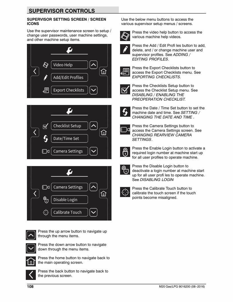
SUPERVISOR CONTROLS
108 M20 Gas/LPG 9016200 (08−2016)
SUPERVISOR SETTING SCREEN / SCREENICONS
Use the supervisor maintenance screen to setup /change user passwords, user machine settings,and other machine setup items.
Press the up arrow button to navigate upthrough the menu items.
Press the down arrow button to navigatedown through the menu items.
Press the home button to navigate back tothe main operating screen.
Press the back button to navigate back tothe previous screen.
Use the below menu buttons to access thevarious supervisor setup menus / screens.
Press the video help button to access thevarious machine help videos.
Press the Add / Edit Profi les button to add,delete, and / or change machine user andsupervisor profiles. See ADDING /EDITING PROFILES.
Press the Export Checklists button toaccess the Export Checklists menu. SeeEXPORTING CHECKLISTS.
Press the Checklists Setup button toaccess the Checklist Setup menu. SeeDISABLING / ENABLING THEPREOPERATION CHECKLIST.
Press the Date / Time Set button to set themachine date and time. See SETTING /CHANGING THE DATE AND TIME .
Press the Camera Settings button toaccess the Camera Settings screen. SeeCHANGING REARVIEW CAMERASETTINGS.
Press the Enable Login button to activate arequired login number at machine start upfor all user profiles to operate machine.
Press the Disable Login button todeactivate a login number at machine startup for all user profi les to operate machine.See DISABLING LOGIN
Press the Calibrate Touch button tocalibrate the touch screen if the touchpoints become misaligned.
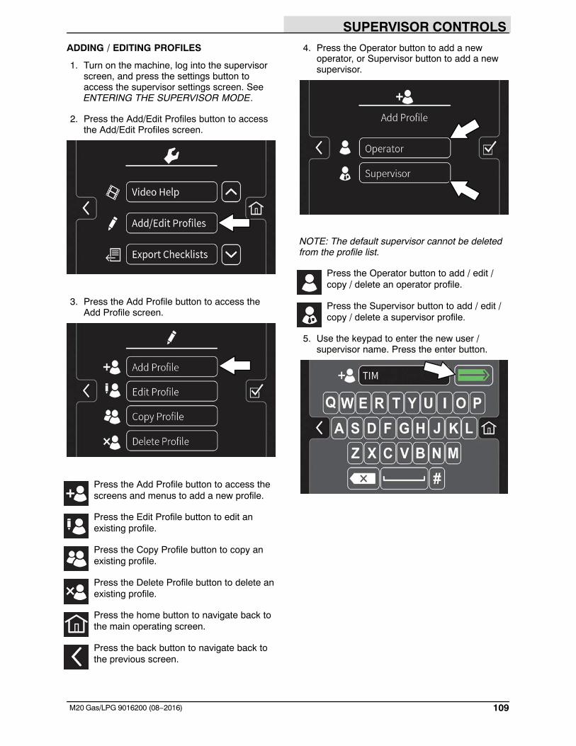
SUPERVISOR CONTROLS
109M20 Gas/LPG 9016200 (08−2016)
ADDING / EDITING PROFILES
1. Turn on the machine, log into the supervisorscreen, and press the settings button toaccess the supervisor settings screen. SeeENTERING THE SUPERVISOR MODE.
2. Press the Add/Edit Profiles button to accessthe Add/Edit Profiles screen.
3. Press the Add Profile button to access theAdd Profile screen.
Press the Add Profile button to access thescreens and menus to add a new profile.
Press the Edit Profile button to edit anexisting profile.
Press the Copy Profile button to copy anexisting profile.
Press the Delete Profile button to delete anexisting profile.
Press the home button to navigate back tothe main operating screen.
Press the back button to navigate back tothe previous screen.
4. Press the Operator button to add a newoperator, or Supervisor button to add a newsupervisor.
NOTE: The default supervisor cannot be deletedfrom the profile list.
Press the Operator button to add / edit /copy / delete an operator profile.
Press the Supervisor button to add / edit /copy / delete a supervisor profile.
5. Use the keypad to enter the new user /supervisor name. Press the enter button.
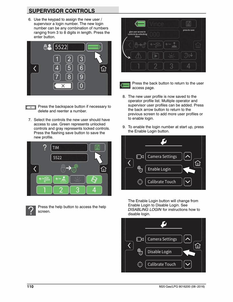
SUPERVISOR CONTROLS
110 M20 Gas/LPG 9016200 (08−2016)
6. Use the keypad to assign the new user /supervisor a login number. The new loginnumber can be any combination of numbersranging from 3 to 8 digits in length. Press theenter button.
Press the backspace button if necessary todelete and reenter a number.
7. Select the controls the new user should haveaccess to use. Green represents unlockedcontrols and gray represents locked controls.Press the flashing save button to save thenew profile.
Press the help button to access the helpscreen.
Press the back button to return to the useraccess page.
8. The new user profile is now saved to theoperator profile list. Multiple operator andsupervisor user profiles can be added. Pressthe back arrow button to return to theprevious screen to add more user profiles orto enable login.
9. To enable the login number at start up, pressthe Enable Login button.
The Enable Login button will change fromEnable Login to Disable Login. SeeDISABLING LOGIN for instructions how todisable login.
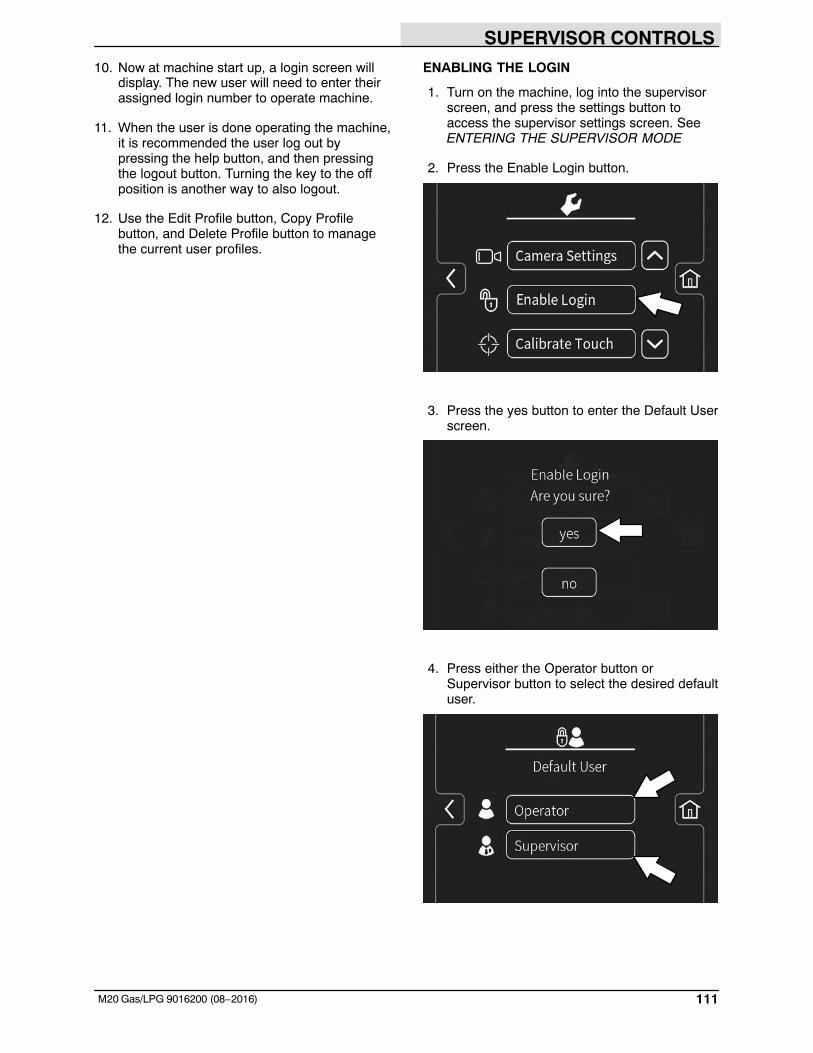
SUPERVISOR CONTROLS
111M20 Gas/LPG 9016200 (08−2016)
10. Now at machine start up, a login screen willdisplay. The new user will need to enter theirassigned login number to operate machine.
11. When the user is done operating the machine,it is recommended the user log out bypressing the help button, and then pressingthe logout button. Turning the key to the offposition is another way to also logout.
12. Use the Edit Profile button, Copy Profilebutton, and Delete Profile button to managethe current user profiles.
ENABLING THE LOGIN
1. Turn on the machine, log into the supervisorscreen, and press the settings button toaccess the supervisor settings screen. SeeENTERING THE SUPERVISOR MODE
2. Press the Enable Login button.
3. Press the yes button to enter the Default Userscreen.
4. Press either the Operator button orSupervisor button to select the desired defaultuser.
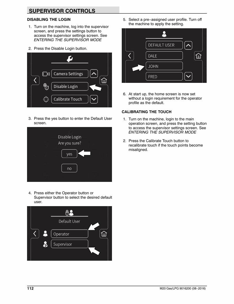
SUPERVISOR CONTROLS
112 M20 Gas/LPG 9016200 (08−2016)
DISABLING THE LOGIN
1. Turn on the machine, log into the supervisorscreen, and press the settings button toaccess the supervisor settings screen. SeeENTERING THE SUPERVISOR MODE
2. Press the Disable Login button.
3. Press the yes button to enter the Default Userscreen.
4. Press either the Operator button orSupervisor button to select the desired defaultuser.
5. Select a pre−assigned user profile. Turn offthe machine to apply the setting.
6. At start up, the home screen is now setwithout a login requirement for the operatorprofile as the default.
CALIBRATING THE TOUCH
1. Turn on the machine, login to the mainoperation screen, and press the setting buttonto access the supervisor settings screen. SeeENTERING THE SUPERVISOR MODE
2. Press the Calibrate Touch button torecalibrate touch if the touch points becomemisaligned.
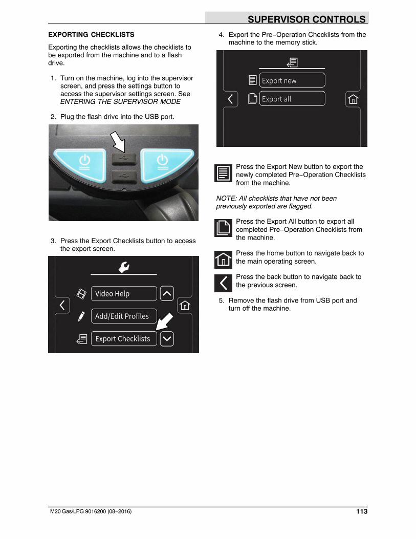
SUPERVISOR CONTROLS
113M20 Gas/LPG 9016200 (08−2016)
EXPORTING CHECKLISTS
Exporting the checklists allows the checklists tobe exported from the machine and to a flashdrive.
1. Turn on the machine, log into the supervisorscreen, and press the settings button toaccess the supervisor settings screen. SeeENTERING THE SUPERVISOR MODE
2. Plug the flash drive into the USB port.
3. Press the Export Checklists button to accessthe export screen.
4. Export the Pre−Operation Checklists from themachine to the memory stick.
Press the Export New button to export thenewly completed Pre−Operation Checklistsfrom the machine.
NOTE: All checklists that have not beenpreviously exported are flagged.
Press the Export All button to export allcompleted Pre−Operation Checklists fromthe machine.
Press the home button to navigate back tothe main operating screen.
Press the back button to navigate back tothe previous screen.
5. Remove the flash drive from USB port andturn off the machine.
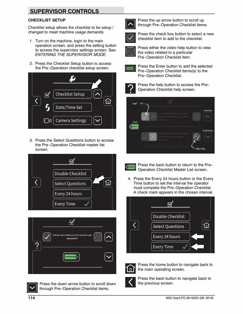
SUPERVISOR CONTROLS
114 M20 Gas/LPG 9016200 (08−2016)
CHECKLIST SETUP
Checklist setup allows the checklist to be setup /changed to meet machine usage demands.
1. Turn on the machine, login to the mainoperation screen, and press the setting buttonto access the supervisor settings screen. SeeENTERING THE SUPERVISOR MODE.
2. Press the Checklist Setup button to accessthe Pre−Operation checklist setup screen.
3. Press the Select Questions button to accessthe Pre−Operation Checklist master listscreen.
Press the down arrow button to scroll downthrough Pre−Operation Checklist items.
Press the up arrow button to scroll upthrough Pre−Operation Checklist items.
Press the check box button to select a newchecklist item to add to the checklist.
Press either the video help button to viewthe video related to a particularPre−Operation Checklist item.
Press the Enter button to add the selectedPre−Operation Checklist items(s) to thePre−Operation Checklist.
Press the help button to access the Pre−Operation Checklist help screen.
Press the back button to return to the Pre−Operation Checklist Master List screen.
4. Press the Every 24 hours button or the EveryTime button to set the interval the operatormust complete the Pre−Operation Checklist.A check mark appears in the chosen interval.
Press the home button to navigate back tothe main operating screen.
Press the back button to navigate back tothe previous screen.
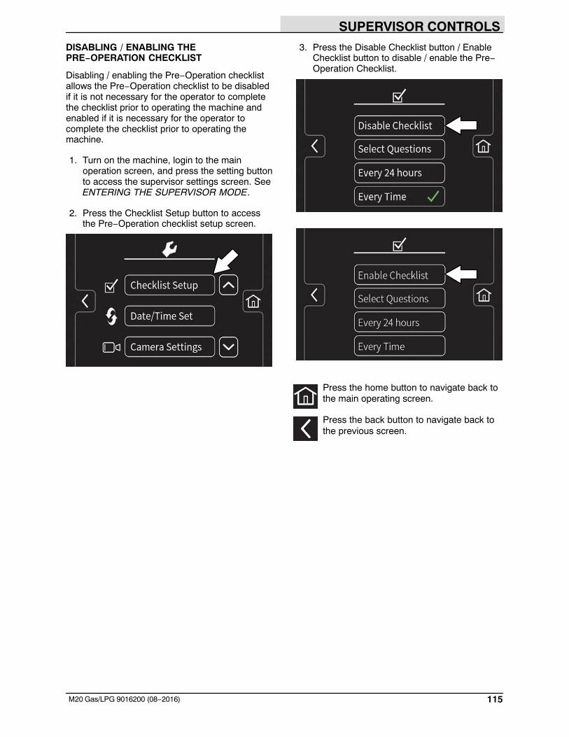
SUPERVISOR CONTROLS
115M20 Gas/LPG 9016200 (08−2016)
DISABLING / ENABLING THEPRE−OPERATION CHECKLIST
Disabling / enabling the Pre−Operation checklistallows the Pre−Operation checklist to be disabledif it is not necessary for the operator to completethe checklist prior to operating the machine andenabled if it is necessary for the operator tocomplete the checklist prior to operating themachine.
1. Turn on the machine, login to the mainoperation screen, and press the setting buttonto access the supervisor settings screen. SeeENTERING THE SUPERVISOR MODE.
2. Press the Checklist Setup button to accessthe Pre−Operation checklist setup screen.
3. Press the Disable Checklist button / EnableChecklist button to disable / enable the Pre−Operation Checklist.
Press the home button to navigate back tothe main operating screen.
Press the back button to navigate back tothe previous screen.
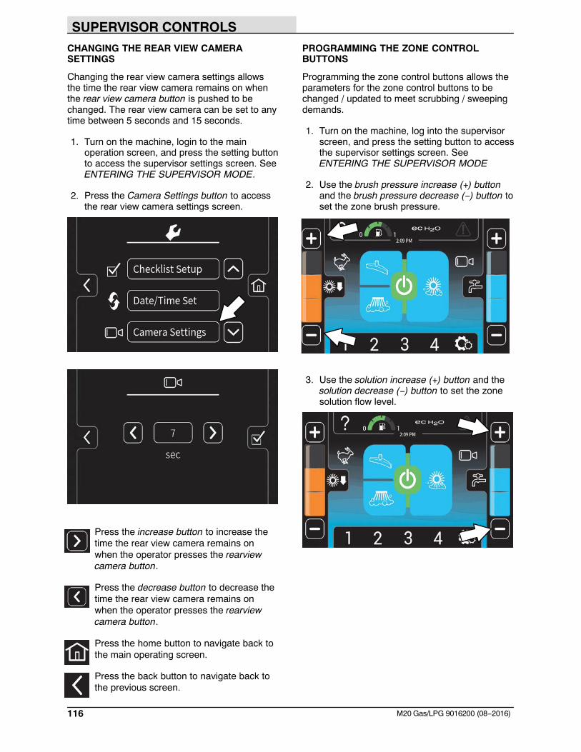
SUPERVISOR CONTROLS
116 M20 Gas/LPG 9016200 (08−2016)
CHANGING THE REAR VIEW CAMERASETTINGS
Changing the rear view camera settings allowsthe time the rear view camera remains on whenthe rear view camera button is pushed to bechanged. The rear view camera can be set to anytime between 5 seconds and 15 seconds.
1. Turn on the machine, login to the mainoperation screen, and press the setting buttonto access the supervisor settings screen. SeeENTERING THE SUPERVISOR MODE.
2. Press the Camera Settings button to accessthe rear view camera settings screen.
Press the increase button to increase thetime the rear view camera remains onwhen the operator presses the rearviewcamera button.
Press the decrease button to decrease thetime the rear view camera remains onwhen the operator presses the rearviewcamera button.
Press the home button to navigate back tothe main operating screen.
Press the back button to navigate back tothe previous screen.
PROGRAMMING THE ZONE CONTROLBUTTONS
Programming the zone control buttons allows theparameters for the zone control buttons to bechanged / updated to meet scrubbing / sweepingdemands.
1. Turn on the machine, log into the supervisorscreen, and press the setting button to accessthe supervisor settings screen. SeeENTERING THE SUPERVISOR MODE
2. Use the brush pressure increase (+) buttonand the brush pressure decrease (−) button toset the zone brush pressure.
3. Use the solution increase (+) button and thesolution decrease (−) button to set the zonesolution flow level.
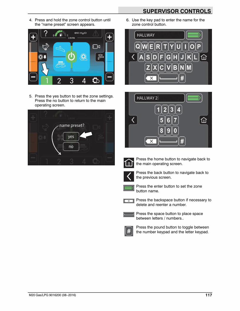
SUPERVISOR CONTROLS
117M20 Gas/LPG 9016200 (08−2016)
4. Press and hold the zone control button untilthe “name preset” screen appears.
5. Press the yes button to set the zone settings.Press the no button to return to the mainoperating screen.
6. Use the key pad to enter the name for thezone control button.
Press the home button to navigate back tothe main operating screen.
Press the back button to navigate back tothe previous screen.
Press the enter button to set the zonebutton name.
Press the backspace button if necessary todelete and reenter a number.
Press the space button to place spacebetween letters / numbers..
Press the pound button to toggle betweenthe number keypad and the letter keypad.
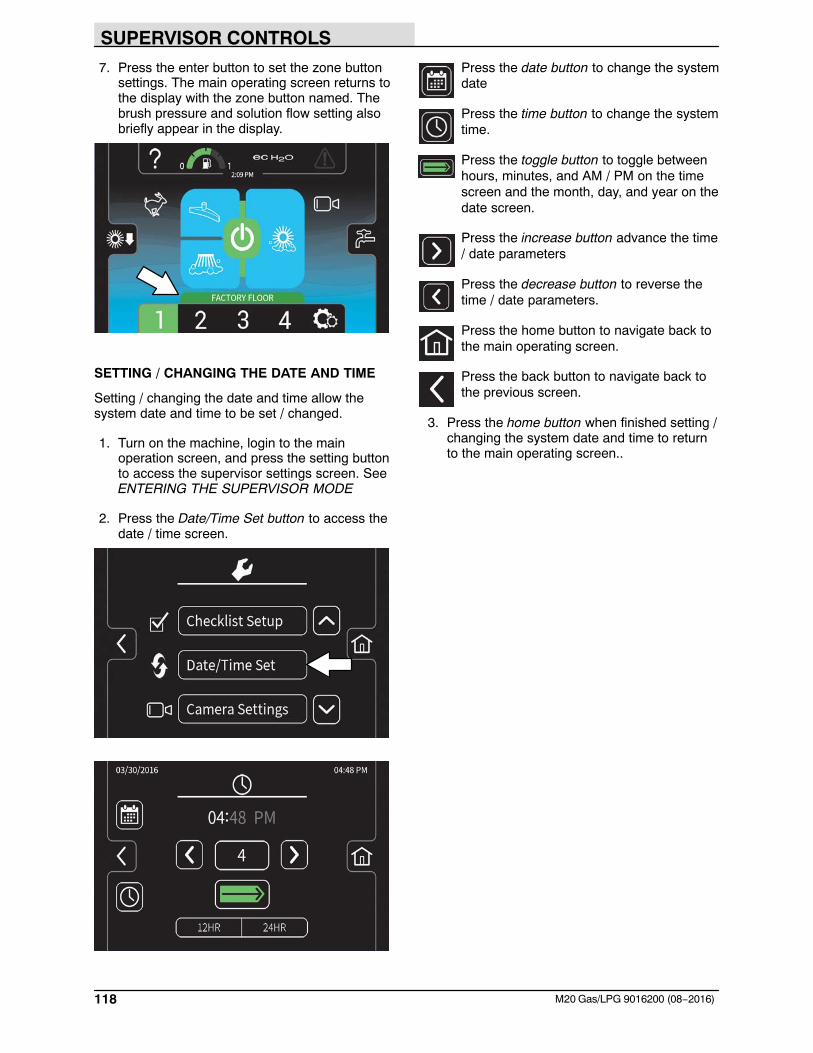
SUPERVISOR CONTROLS
118 M20 Gas/LPG 9016200 (08−2016)
7. Press the enter button to set the zone buttonsettings. The main operating screen returns tothe display with the zone button named. Thebrush pressure and solution flow setting alsobriefly appear in the display.
SETTING / CHANGING THE DATE AND TIME
Setting / changing the date and time allow thesystem date and time to be set / changed.
1. Turn on the machine, login to the mainoperation screen, and press the setting buttonto access the supervisor settings screen. SeeENTERING THE SUPERVISOR MODE
2. Press the Date/Time Set button to access thedate / time screen.
Press the date button to change the systemdate
Press the time button to change the systemtime.
Press the toggle button to toggle betweenhours, minutes, and AM / PM on the timescreen and the month, day, and year on thedate screen.
Press the increase button advance the time/ date parameters
Press the decrease button to reverse thetime / date parameters.
Press the home button to navigate back tothe main operating screen.
Press the back button to navigate back tothe previous screen.
3. Press the home button when finished setting /changing the system date and time to returnto the main operating screen..
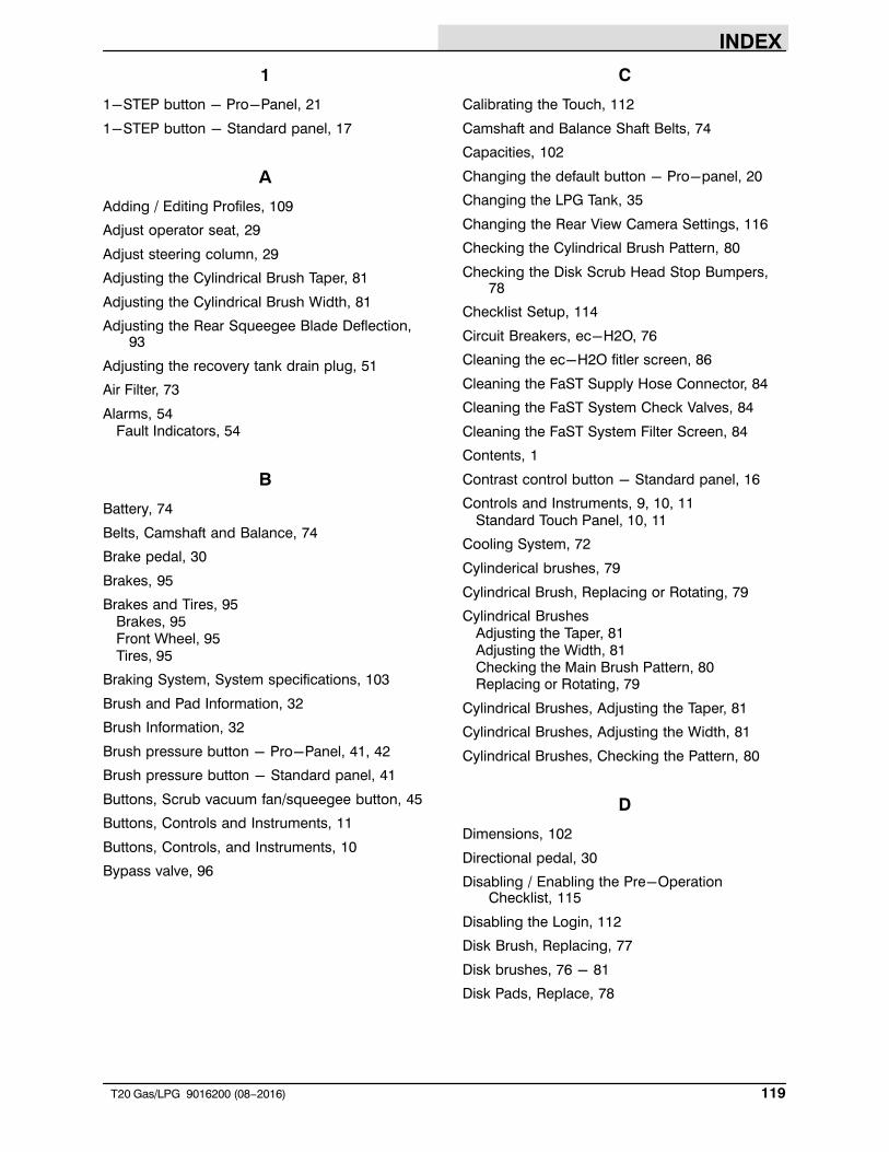
INDEX
119T20 Gas/LPG 9016200 (08−2016)
1
1-STEP button - Pro-Panel, 21
1-STEP button - Standard panel, 17
A
Adding / Editing Profiles, 109
Adjust operator seat, 29
Adjust steering column, 29
Adjusting the Cylindrical Brush Taper, 81
Adjusting the Cylindrical Brush Width, 81
Adjusting the Rear Squeegee Blade Deflection,93
Adjusting the recovery tank drain plug, 51
Air Filter, 73
Alarms, 54Fault Indicators, 54
B
Battery, 74
Belts, Camshaft and Balance, 74
Brake pedal, 30
Brakes, 95
Brakes and Tires, 95Brakes, 95Front Wheel, 95Tires, 95
Braking System, System specifications, 103
Brush and Pad Information, 32
Brush Information, 32
Brush pressure button - Pro-Panel, 41, 42
Brush pressure button - Standard panel, 41
Buttons, Scrub vacuum fan/squeegee button, 45
Buttons, Controls and Instruments, 11
Buttons, Controls, and Instruments, 10
Bypass valve, 96
C
Calibrating the Touch, 112
Camshaft and Balance Shaft Belts, 74
Capacities, 102
Changing the default button - Pro-panel, 20
Changing the LPG Tank, 35
Changing the Rear View Camera Settings, 116
Checking the Cylindrical Brush Pattern, 80
Checking the Disk Scrub Head Stop Bumpers,78
Checklist Setup, 114
Circuit Breakers, ec-H2O, 76
Cleaning the ec-H2O fitler screen, 86
Cleaning the FaST Supply Hose Connector, 84
Cleaning the FaST System Check Valves, 84
Cleaning the FaST System Filter Screen, 84
Contents, 1
Contrast control button - Standard panel, 16
Controls and Instruments, 9, 10, 11Standard Touch Panel, 10, 11
Cooling System, 72
Cylinderical brushes, 79
Cylindrical Brush, Replacing or Rotating, 79
Cylindrical BrushesAdjusting the Taper, 81Adjusting the Width, 81Checking the Main Brush Pattern, 80Replacing or Rotating, 79
Cylindrical Brushes, Adjusting the Taper, 81
Cylindrical Brushes, Adjusting the Width, 81
Cylindrical Brushes, Checking the Pattern, 80
D
Dimensions, 102
Directional pedal, 30
Disabling / Enabling the Pre-OperationChecklist, 115
Disabling the Login, 112
Disk Brush, Replacing, 77
Disk brushes, 76 - 81
Disk Pads, Replace, 78
INDEX
120 T20 Gas/LPG 9016200 (08−2016)
Disk Scrub Brushes, Replacing, 77
Disk Scrub Head Stop Bumpers, Checking, 78
Double Scrubbing, 45
Draining and Cleaning the Recovery Tank, 49Draining the Recovery Tank with the Drain
Hose, 49Draining the Recovery Tank with the Drain Plug,
50
Draining and Cleaning the Solution Tank, 52
Draining the Recovery Tank with the Drain Hose,49
Draining the Recovery Tank with the Drain Plug,50
E
ec-H20 module flush switch, 85
ec-H2O button - Pro-Panel, 39
Zone control buttons - Pro-Panel, 23
ec-H2O button - Standard panel, 39
ec-H2O Module Flush Procedure, 85
Emptying and Cleaning the Debris Tray(Cylindrical scrub heads only), 47
Enabling the Login, 111
Engine, 72Air Filter, 73Camshaft and Balance Shaft Belts, 74Cooling System, 72Engine Belt, 74Fuel Filter, 73LPG Vaporizer, 73PCV System, 74Spark Plugs, 74Specifications, 103Timing Belt, 74
Engine Belt, 74
Engine Harness Fuses and Relays, 76
Engine Oil, 68
Engine speed button - Pro-Panel, 22
Engine Speed Button - Standard panel, 16
Entering the Supervisor Mode, 107
Entering the Supervisor Mode - First Time UseOnly, 106
ES button - Pro-Panel, 40
ES button - Standard panel, 40
Exporting Checklists, 113
F
FaST button - Pro-Panel, 40
FaST button - Standard panel, 40
FaST System, 83Cleaning the FaST Supply Hose Connector, 84Cleaning the FaST System Check Valves, 84Cleaning the FaST System Filter Screen, 84Replacing the FaST−PAK Carton, 83
Fault / Alert indicators - Pro-Panel, 54
Fault / Alert indicators - Standard panel, 54
Fault Indicators, 54
Filling the Solution Tank, 37Conventional Scrubbing Mode, 37ec−H20 scrubbing (ec−H20 Mode), 37ES (Extended Scrub) Mode − Manually Filling
Tank, 38ES (Extended Scrub) Mode with Auto−Fill, 38Foam scrubbing (FaST Mode), 37
FiltersEngine Air Filter, 73Gasoline Fuel Filter, 73Hydraulic Fluid Filter, 70LPG Fuel Filter, 73
Freeze Protection (Machines with ec-H20system), 99
Freeze Protection (Machines without ec-H20system), 99
Front Wheel Support Bearing, 68
Front Wheel, Torque, 95
Fuel FilterGasoline, 73LPG, 73
Fuel Indicator - Standard controls, 15
Fuses and Relays, 75Engine Harness Fuses and Relays, 76Optional, 76Relay Panel Fuses and Relays, 75
Fuses, Relays, and Circuit Breakers, Circuitbreakers (ec-H2O), 76
INDEX
121T20 Gas/LPG 9016200 (08−2016)
H
Hazard Light Switch (Option), 28
Headlights, 28
Help button - Pro-Panel, 24
High Presure Washer (Option), 60
Hour Meter, 15
How the Machine Works, 31
Hydraulic Fluid, 71
Hydraulic Hoses, 71
Hydraulic System, System specifications, 103
Hydraulics, 70Drain and refill hydraulic fluid reservoir, 70Hydraulic Fluid, 71Hydraulic Hoses, 71Replace the filler cap, 70Replace the hydraulic fluid filter, 70Replace the hydraulic strainer outlet, 70
I
IndicatorsFault Indicators, 54Hour Meter, 15
L
Leveling the Rear Squeegee, 92
LightsHazard Light Switch (Option), 28Headlights, 28Operating, 28
LPG Vaporizer, 73
Lubrication, 68Engine Oil, 68Front Wheel Support Bearing, 68Pivot Shaft (Disk Brushes), 69Rear wheel bearings, 69Squeegee Caster Bearings, 68Steering Cylinder Bearing, 68Torque Tubes (Cylindrical Brushes), 69Torque Tubes (Disk Brushes), 69
M
Machine components, 8
Machine Dimensions, 105
Machine Jacking, 98
Machine Operation, Pre-Operation Checklist, 34
Machine PerformanceAisle Turnaround Width, 102Climb and Descent Angles, 102Travel Speed (Maximum), 102
Machine Specifications, 102 - 105
Machine status button - Pro-Panel, 19
Machine Troubleshooting, 62
Main scrub brush button - Standard panel, 18
Maintenance, 64 - 88Cylinderical brushes, 79 − 84Disk brushes, 76 − 81Yellow touch points, 68
Maintenance Chart, 65
O
Operating Lights, 28
Operating temperature, 33
Operation, 8 - 32
Operation of controls - Pro-Panel, 191−STEP button, 21Brush pressure button, 41, 42Changing the default button, 20ec−H2O button, 39Engine speed button, 22ES button, 40FaST button, 40Fault / Alert indicators, 54Help button, 24Machine status button, 19Pro−Check Pre−Operation checklist, 27Pro−ID login screen, 19Scrubbing main brush button, 21Scrubbing side brush button, 22Scrubbing vacuum fan / squeegee button, 21Solution on / off buttons, 22Sweeping side brush button, 23Video help button, 26Zone control buttons, 23
Operation of controls - Standard controlsFuel Indicator, 15Recovery tank full indicator, 15

INDEX
122 T20 Gas/LPG 9016200 (08−2016)
Operation of controls - Standard panel, 15, 281−STEP button, 17Brush pressure button, 41Contrast control button, 16ec−H2O button, 39Engine speed button, 16ES button, 40FaST button, 40Fault / Alert indicators, 54Main scrub brush button, 18Side scrub brush button, 17Solution flow button, 42Solution on / off button, 18Solution tank indicator, 16Vacuum fan / squeegee button, 17
Operator seat, 29
Optional Relays, 76
Options, 56Hazard Light, 28High Presure Washer, 60Power Wand (Option), 58Spray Nozzle (Option), 56Squeegee protectors, 30Vacuum Wand (Option), 57
P
Pad Driver, Replacing, 77
Pad Information, 32
Parking brake pedal, 30
PCV System, 74
PedalsBrake pedal, 30Directional pedal, 30Parking brake pedal, 30
Pivot Shaft (Disk Brushes), 69
Power Wand (Option), 58
Pre-Operation Checklist, 34
Priming the ec-H20 system, 101
Pro-Check Pre-Operation checklist -Pro-Panel, 27
Pro-ID login screen - Pro-Panel, 19
Pro-Panel Supervisor Controls, 106Adding / Editing Profiles, 109Calibrating the Touch, 112Changing the Rear View Camera Settings, 116Checklist Setup, 114Disabling / Enabling the Pre−Operation
Checklist, 115
Disabling the Login, 112Enabling the Login, 111Entering the Supervisor Mode, 107Entering the Supervisor Mode − First Time Use
Only, 106Exporting Checklists, 113Programming the Zone Control Buttons, 116Setting / Changing the Date and Time, 118Supervisor Setting Screen / Screen Icons, 108
Programming the Zone Control Buttons, 116
Propelling Motor, 95Torque Shaft Nut, 95
Pushing or Towing the Machine, 96
Pushing, Towing, and Transporting the Machine,96
Pushing or Towing the Machine, 96Transporting the Machine, 96
R
Radiator, 72Check hoses and clamps, 72Clean core exterior, 72
Rear SqueegeeAdjusting the Rear Squeegee Blade Deflection,
93Leveling the Rear Squeegee, 92
Rear Squeegee Blade, Replacing (or Rotating)the Rear Squeegee Blade, 87
Rear Squeegee, Replacing (or Rotating), 87
Rear Wheel bearings, 69
Recovery tank full indicator - Standard controls,15
Recovery Tank Seal, 94
Relay Panel Fuses and Relays, 75
Replacing (or Rotating) the Rear SqueegeeBlades, 87
Replacing Cylindrical Scrub Brushes, 79
Replacing or Rotating Cylindrical Brushes, 79
Replacing or Rotating the Side SqueegeeBlades, 89
Replacing the FaST-PAK Carton, 83
Replacing the Side Brush (Option), 82
Replacing the Side Brush Squeegee Blade(Option), 91
Rotating Cylindrical Scrub Brushes, 79
INDEX
123T20 Gas/LPG 9016200 (08−2016)
S
SafetyInstructions, 4 − 6Labels, 6 − 8
Scrub brushes, Cylinderical brushes, 79
Scrub Brushes and Pads, 76Disk brushes, 76Replacing Disk Brushes or Pad Driver, 77Replacing Scrub Pads, 78
Scrub Head Skirt, 94
Scrub Pads, Replace, 78
Scrubbing - Pro-Panel, 44
Scrubbing - Standard panel, 43
Scrubbing main brush button - Pro-Panel, 21
Scrubbing side brush button - Pro-Panel, 22
Scrubbing vacuum fan / squeegee button -Pro-Panel, 21
Seals, 94Recovery Tank Seal, 94Solution Tank Seals, 94
Seat belts, 29
Seat, Operator, 29
Setting / Changing the Date and Time, 118
Setting Brush Pressure, 41, 42
Setting ec-H20 Mode, 39
Setting ES (Extended Scrub) Mode, 40
Setting ES Solution Flow, 42
Setting FaST Mode, 40
Setting Scrub Modes, 39Setting Brush Pressure, 41, 42Setting ec−H20 Mode, 39Setting ES (Extended Scrub) Mode, 40Setting ES Solution Flow, 42Setting FaST Mode, 40Setting Solution Flow, 42
ES (Extended Scrub) Mode, 42
Setting the Engine Speed, 16
Side Brush (Option), 82Replacing the Side Brush, 82Replacing the Side Brush Squeegee 91
Side Brush Squeegee (Option), Replacing, 91
Side Brush, Replacing, 82
Side scrub brush button - Standard panel, 17
Side Squeegee Blades, 89Replacing or Rotating the Side Squeegee
Blades, 89
Side Squeegee Blades, Replacing or Rotating,89
Skirts and Seals, 94Recovery Tank Seal, 94Scrub Head Skirt, 94Solution Tank Seals, 94
Solution flow button - Standard panel, 42
Solution on / off button - Standard panel, 18
Solution on / off buttons - Pro-Panel, 22
Solution tank indicator - Standard panel, 16
Solution Tank Seals, 94
Spark Plugs, 74
Specifications, 102 - 105Braking system, 103ec−H20 system, 104FaST System, 104Hydraulic System, 103Machine Capacities, 102Machine Dimensions, 102Machine Performance, 102Power Type, 103Steering, 103Tires, 103
Spray Nozzle (Option), 56
Squeegee Blades, 87Adjusting the Rear Squeegee Blade Deflection,
93Leveling the Rear Squeegee, 92Replacing (or Rotating) the Rear Squeegee
Blades, 87Replacing or Rotating the Side Squeegee
Blades, 89Replacing the Side Brush Squeegee Blade
(Option), 91
Squeegee Caster Bearings, 68
Squeegee Protectors (Option), 30
Standard Touch Panel, 10, 11
Starting the Machine, 36
Steering, Specifications, 103
Steering column tilt knob, 29
Steering Cylinder Bearing, 68
Storage Information, 98Freeze Protection, 99Priming the ec−H20 system, 101Storing the Machine, 98
Supervisor Controls, 106 - 130
Supervisor Setting Screen / Screen Icons, 108
Sweeping side brush button - Pro-Panel, 23
Symbol definitions, 12 - 14
INDEX
124 T20 Gas/LPG 9016200 (08−2016)
T
Temperature, Operating, 33
Timing Belt, 74
Tires, 95Specifications, 103
Torque Shaft Nut, Propelling Motor, 95
Torque Tubes (Cylindrical Brushes), 69
Torque Tubes (Disk Brushes), 69
Touch points, yellow, 68
Towing the Machine, 96
Transporting the Machine, 96
Turning Off the Machine, 36
V
Vacuum fan / squeegee button - Standardpanel, 17
Vacuum Wand (Option), 57
Vaporizer, 73
Video help button - Pro-Panel, 26
W
Warning Indicators, 54Fault Indicators, 54
Water Pickup Mode (No Scrubbing), 46
Wheels, 95
While Operating the Machine, 33
ZZone control buttons, 23