gas quench steel hardenability standard - wpi...
TRANSCRIPT
1
Gas Quench Steel Hardenability Standard
Research Team
Yuan Lu
Yiming Rong
Richard D. Sisson, Jr.
Introduction
Quenching is the rapid cooling process from an elevated temperature. Compared to water and oil
quench medium, high pressure and velocity gas is preferred to quench medium and high
hardenability steel, with the potential to reduce distortion, stress and cracks. Currently, no standard
test exists to characterize the gas quench steel hardenability and measure the performance of
industrial gas quench furnaces.
In this project, the fundamental difference between the liquid and gas quenching, heat transfer
coefficient (HTC), was investigated. It has been found that gas quenching with constant HTC
cannot generate the similar cooling curves compared to liquid quenching. Limitations on current
gas quench steel hardenability tests were also reviewed. Critical HTC, a concept like critical
diameter in liquid quenching, was successfully applied to describe the gas quench hardenability of
steel. An attempt to use critical HTC test bar to measure the HTC distribution of gas quench
furnace was made.
Methodology
The project focused on two objectives:
The primary objective of this project is to establish a standard method to evaluate gas quench steel
hardenability. Quenchant compositions, gas pressure and velocity should be considered. The
steel’s hardenability is defined by parameters of standard sample geometry and standard quench
condition.
The secondary objective is to develop a method to evaluate the cooling performance in gas quench
system. Standard specimen and instruments are necessary to characterize the cooling performance.
The simulation is utilized to understand the relationship between steel hardenability and cooling
performance in gas quench system.
2
Salient results
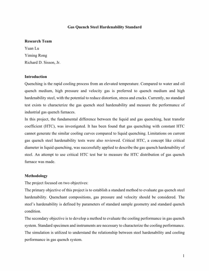
The critical HTC test is proposed based on Grossmann test [1]. In critical HTC test, cylinder
samples with the same geometry are used (bar with 25mm diameter and 100mm length). The
sample sketch is shown in Figure 1. The gas flow is assumed the same at the sample end and the
sample side. Gas flow is fully-developed, turbulent annular flow. In this condition, the gas pressure
and velocity are steady during gas quenching. In the test, different gas quench HTC conditions
(gas types and compositions, pressure and velocity) are applied to the samples with the same
geometry. After quenching, samples are sectioned at mid-length and the sample that has 50%
martensite at its center is selected. The applied gas quench HTC on this sample is designated as
the critical HTC.
Figure 1. Sketch of critical HTC test
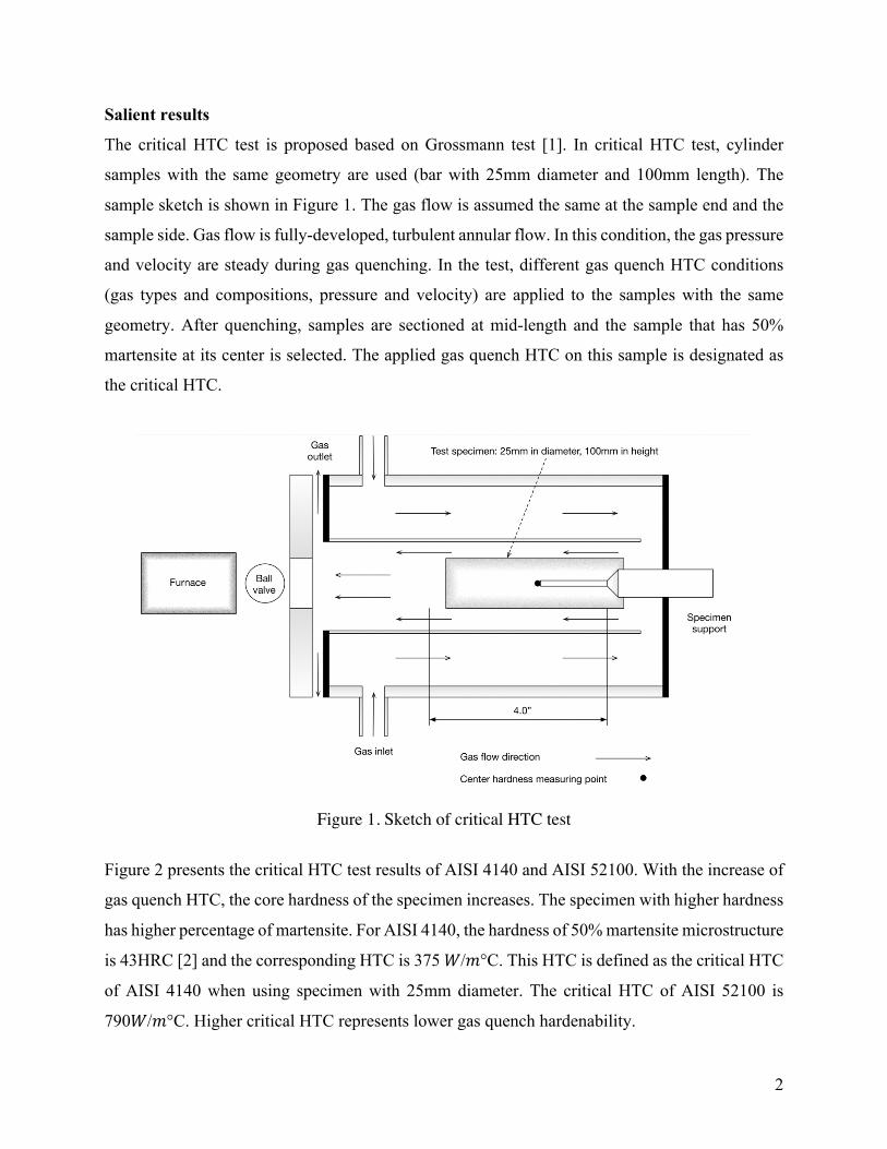
Figure 2 presents the critical HTC test results of AISI 4140 and AISI 52100. With the increase of
gas quench HTC, the core hardness of the specimen increases. The specimen with higher hardness
has higher percentage of martensite. For AISI 4140, the hardness of 50% martensite microstructure
is 43HRC [2] and the corresponding HTC is 375 𝑊/𝑚°C. This HTC is defined as the critical HTC
of AISI 4140 when using specimen with 25mm diameter. The critical HTC of AISI 52100 is
790𝑊/𝑚°C. Higher critical HTC represents lower gas quench hardenability.
3
Figure 2. (a) Critical HTC test of AISI 4140 steel, (b) Critical HTC test of AISI 52100 steel
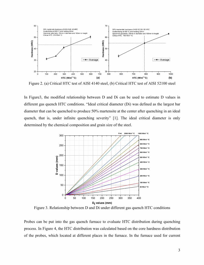
In Figure3, the modified relationship between D and Di can be used to estimate D values in
different gas quench HTC conditions. “Ideal critical diameter (Di) was defined as the largest bar
diameter that can be quenched to produce 50% martensite at the center after quenching in an ideal
quench, that is, under infinite quenching severity” [1]. The ideal critical diameter is only
determined by the chemical composition and grain size of the steel.
Figure 3. Relationship between D and Di under different gas quench HTC conditions
Probes can be put into the gas quench furnace to evaluate HTC distribution during quenching
process. In Figure 4, the HTC distribution was calculated based on the core hardness distribution
of the probes, which located at different places in the furnace. In the furnace used for current

4
experiment, the lowest hardness and HTC appear at the lower left corner of the rear side. The
workpiece at this location may not get the required microstructure and mechanical properties when
workpieces at other locations meet the requirement.
Figure 4 (a) Hardness distribution at the front side, (b) Hardness distribution at the rear side, (c)
HTC distribution at the front side, (d) HTC distribution at the rear side.
Reference
[1] M.A. Grossmann, E.C. Bain, Principles of heat treatment, American Society for Metals, 1964. [2] J. Dossett and G. E. Totten, ASM Handbook, Volume 4A, Steel Heat Treating Fundamentals and Processes. ASM International, 2013.