gas residential water heaters - ge appliances
TRANSCRIPT
Part No. AP13204-4 (01/05) Pub. No. 49-50103 JR
Manufactured under trademark license by:
Rheem Manufacturing Company2600 Gunter Park Drive East, Montgomery, AL 36109-1413
FOR YOUR SAFETY!— Do not store or use gasoline or other flammable
vapors or liquids or other combustible materialsin the vicinity of this or any other appliance. To do so may result in an explosion or fire.
— WHAT TO DO IF YOU SMELL GAS● Do not try to light any appliance.● Do not touch any electrical switch; do not
use any phone in your building.● Immediately call your gas supplier from a
neighbor’s phone. Follow the gas supplier’sinstructions.
● If you cannot reach your gas supplier, call the fire department.
● Do not return to your home until authorized by the gas supplier or fire department.
— Improper installation, adjustment, alteration,service or maintenance can cause propertydamage, personal injury or death. Refer to this manual. Installation and service must beperformed by a qualified installer, service agency or the gas supplier.
!
WARNING: If the information in these instructions is not followed exactly, a fire orexplosion may result causing property damage, personal injury or death.!
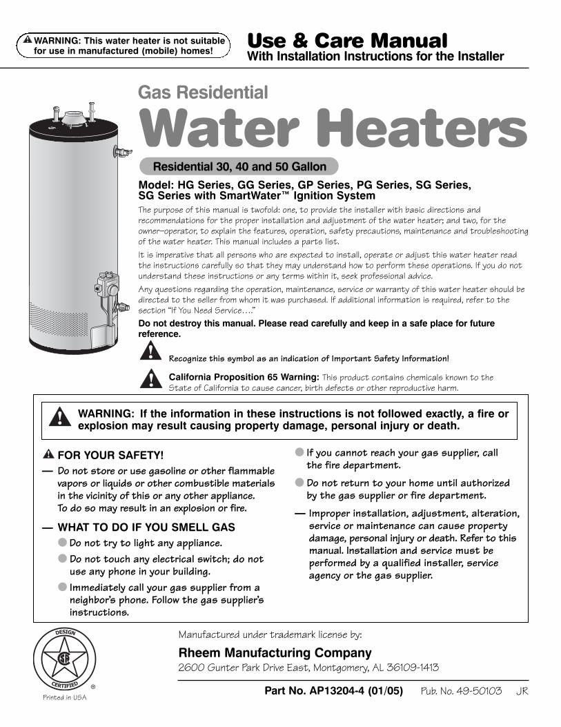
Model: HG Series, GG Series, GP Series, PG Series, SG Series,SG Series with SmartWater™ Ignition SystemThe purpose of this manual is twofold: one, to provide the installer with basic directions andrecommendations for the proper installation and adjustment of the water heater; and two, for theowner–operator, to explain the features, operation, safety precautions, maintenance and troubleshootingof the water heater. This manual includes a parts list.It is imperative that all persons who are expected to install, operate or adjust this water heater readthe instructions carefully so that they may understand how to perform these operations. If you do notunderstand these instructions or any terms within it, seek professional advice.Any questions regarding the operation, maintenance, service or warranty of this water heater should bedirected to the seller from whom it was purchased. If additional information is required, refer to thesection “If You Need Service….”Do not destroy this manual. Please read carefully and keep in a safe place for futurereference.
Recognize this symbol as an indication of Important Safety Information!
California Proposition 65 Warning: This product contains chemicals known to the State of California to cause cancer, birth defects or other reproductive harm.!
!
Residential 30, 40 and 50 Gallon
Use & Care ManualWith Installation Instructions for the Installer
Printed in USA
Water HeatersGas Residential
DESIGN
CERTIFIED ®
WARNING: This water heater is not suitable for use in manufactured (mobile) homes!
!
Safety Information
Safety Precautions. . . . . . . 3–6
LP Gas Models . . . . . . . . . . . . . 5
Installation Instructions
Location. . . . . . . . . . . . . . . . . . . . 7
Water Supply Connections. . . 9
Gas Supply. . . . . . . . . . . . . . . . . 11
Pipe Insulation . . . . . . . . . . . . . 13
Heat Traps . . . . . . . . . . . . . . . . 13
Installation Checklist . . . . . . . 14
Potable/Space Heating . . . . . 15
Operating Instructions
Lighting Instructions . . . . . . . 16
Water Temperature. . . . . . 17, 18
Care and Cleaning
Draining . . . . . . . . . . . . . . . . . . . 19
Maintenance. . . . . . . . . . . . . . . 19
Burner Inspection. . . . . . . . . . 20
Extended Shut-Down . . . . . . 20
Troubleshooting Tips
Before You CallFor Service . . . . . . . . . . . . . 21, 22
Customer Service
Parts List . . . . . . . . . . . . . . . . . 25
If you need service . . . . . . . . . 26
Product Registration . . . 27, 28
Inside you will find many helpful hints on how to use and maintainyour water heater properly. Just a little preventive care on your partcan save you time and money over the life of your water heater.
You’ll find many answers to common problems in the Before You CallFor Service section. If you review our chart of Troubleshooting Tipsfirst, you may not need to call for service at all.
READ THIS MANUAL
FOR YOUR RECORDSWrite the model and serial numbers here:
#
#You can find them on a label on the appliance.
Staple sales slip or cancelled check here.
Proof of the original purchase date is needed to obtain service underthe warranty.
IMPORTANT!Fill out and return the Consumer Product Registration Card that isin the back of this manual.
If you do need service, you can relax knowing help is only a phone callaway. For service call 800-431-1549.
IF YOU NEED SERVICE
Cus
tom
er S
ervi
ceTr
oubl
esho
otin
g Ti
psC
are
and
Cle
anin
gO
pera
ting
Inst
ruct
ions
Inst
alla
tion
Inst
ruct
ions
Saf
ety
Inst
ruct
ions
2
Your safety and the safety of others are very important. There aremany important safety messages in this manual and on yourappliance. Always read and obey all safety messages.
This is the safety alert symbol. Recognize this symbol as an indication of Important Safety Information! Thissymbol alerts you to potential hazards that can kill or hurt you and others.
All safety messages will follow the safety alert symbol and either theword “DANGER”, “WARNING”, “CAUTION” or “NOTICE”.
These words mean:
DANGER An imminently hazardous situation that willresult in death or serious injury.
WARNING A potentially hazardous situation that couldresult in death or serious injury and/or damageto property.
CAUTION A potentially hazardous situation that mayresult in minor or moderate injury.
Notice: Attention is called to observe a specifiedprocedure or maintain a specific condition.
!
!
!
READ THE SAFETY INFORMATION
!
Safety Instructions
Installation InstructionsO
perating InstructionsC
are and Cleaning
Troubleshooting TipsC
ustomer S
ervice
Be sure to read and understand the entire Use and Care Manual before attempting to install or operate thiswater heater. It may save you time and money. Pay particular attention to the Safety Instructions. Failure tofollow these warnings could result in serious bodily injury or death. Should you have problems understandingthe instructions in this manual, or have any questions, STOP, and get help from a qualified service technician,or the local gas utility.
IMPORTANT SAFETY INFORMATION.READ ALL INSTRUCTIONS BEFORE USING.
3
Failure to install the draft hood and properly vent the water heater to the outdoors asoutlined in the Venting Section of the Installation Instructions in this manual can result inunsafe operation of the water heater. To avoid the risk of fire, explosion, or asphyxiation fromcarbon monoxide, never operate this water heater unless it is properly vented and has anadequate air supply for proper operation. Be sure to inspect the vent system for properinstallation at initial start-up; and at least annually thereafter. Refer to the Care and Cleaningsection of this manual for more information regarding vent system inspection.
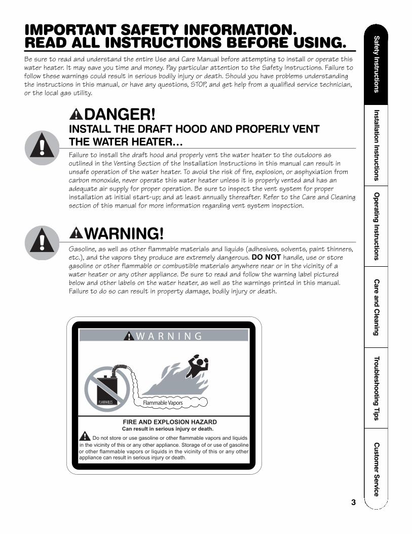
DANGER!INSTALL THE DRAFT HOOD AND PROPERLY VENT THE WATER HEATER…
!
Gasoline, as well as other flammable materials and liquids (adhesives, solvents, paint thinners,etc.), and the vapors they produce are extremely dangerous. DO NOT handle, use or storegasoline or other flammable or combustible materials anywhere near or in the vicinity of awater heater or any other appliance. Be sure to read and follow the warning label picturedbelow and other labels on the water heater, as well as the warnings printed in this manual.Failure to do so can result in property damage, bodily injury or death.
WARNING!!
!
!
FLAMMABLES Flammable Vapors
FIRE AND EXPLOSION HAZARDCan result in serious injury or death.
Do not store or use gasoline or other flammable vapors and liquids
in the vicinity of this or any other appliance. Storage of or use of gasoline
or other flammable vapors or liquids in the vicinity of this or any otherappliance can result in serious injury or death.
W A R N I N G
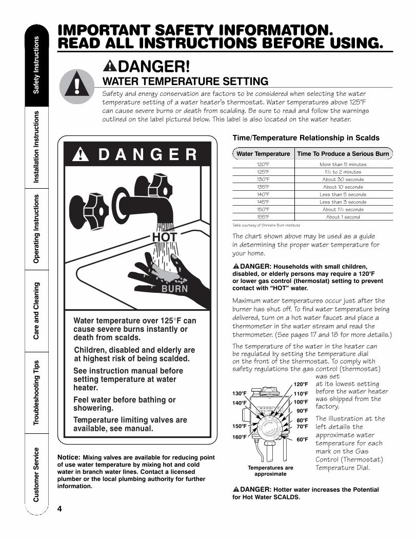
Time/Temperature Relationship in Scalds
Water Temperature Time To Produce a Serious Burn
120°F More than 5 minutes125°F 11/2 to 2 minutes130°F About 30 seconds135°F About 10 seconds140°F Less than 5 seconds145°F Less than 3 seconds150°F About 11/2 seconds155°F About 1 second
Table courtesy of Shriners Burn Institute
The chart shown above may be used as a guide in determining the proper water temperature foryour home.
DANGER: Households with small children,disabled, or elderly persons may require a 120°F or lower gas control (thermostat) setting to preventcontact with “HOT” water.
Maximum water temperatures occur just after theburner has shut off. To find water temperature beingdelivered, turn on a hot water faucet and place athermometer in the water stream and read thethermometer. (See pages 17 and 18 for more details.)The temperature of the water in the heater can be regulated by setting the temperature dial on the front of the thermostat. To comply withsafety regulations the gas control (thermostat)
was set at its lowest settingbefore the water heaterwas shipped from thefactory.
The illustration at theleft details theapproximate watertemperature for eachmark on the GasControl (Thermostat)Temperature Dial.
DANGER: Hotter water increases the Potential for Hot Water SCALDS.!
!
D A N G E R!
HOT
Water temperature over 125°F cancause severe burns instantly ordeath from scalds.
Children, disabled and elderly areat highest risk of being scalded.
See instruction manual beforesetting temperature at waterheater.Feel water before bathing orshowering.Temperature limiting valves areavailable, see manual.
BURN
DANGER!WATER TEMPERATURE SETTING!
Safety and energy conservation are factors to be considered when selecting the watertemperature setting of a water heater’s thermostat. Water temperatures above 125°F can cause severe burns or death from scalding. Be sure to read and follow the warningsoutlined on the label pictured below. This label is also located on the water heater.
Notice: Mixing valves are available for reducing pointof use water temperature by mixing hot and coldwater in branch water lines. Contact a licensedplumber or the local plumbing authority for furtherinformation.
WARMV
AC
ATION
HO
T CAUTION
THE RISK OF SCALDIN
JUR
Y
WATE R IN CRE
AS
ES
H O T TE
R
W A R N I N GREAD ALL INSTRUCTIONSBEFORE LIGHTING
130°F
Temperatures areapproximate
120°F
140°F
150°F
160°F
110°F 100°F
90°F
80°F 70°F
60°F
Cus
tom
er S
ervi
ceTr
oubl
esho
otin
g Ti
psC
are
and
Cle
anin
gO
pera
ting
Inst
ruct
ions
Inst
alla
tion
Inst
ruct
ions
Saf
ety
Inst
ruct
ions
4
IMPORTANT SAFETY INFORMATION.READ ALL INSTRUCTIONS BEFORE USING.

5
Safety Instructions
Installation InstructionsO
perating InstructionsC
are and Cleaning
Troubleshooting TipsC
ustomer S
ervice
LP and natural gas have an odorant added to aid in detecting a gas leak. Some people may notphysically be able to smell or recognize this odorant. If you are unsure or unfamiliar with the smellof LP or natural gas, ask the gas supplier. Other conditions, such as “odorant fade”, which causesthe odorant to diminish in intensity, can also hide or camouflage a gas leak.
DANGER!LIQUIFIED PETROLEUM (LP—PROPANE OR BUTANE) AND NATURAL GAS MODELS
!
● Water heaters utilizing LP gas are differentfrom natural gas models. A natural gaswater heater will not function safely on LPgas and vice versa.
● No attempt should ever be made toconvert the water heater from natural gasto LP gas. To avoid possible equipmentdamage, personal injury or fire, do notconnect the water heater to a fuel typenot in accordance with the unit data plate.LP for LP units. Natural gas for naturalgas units. These units are not certified forany other fuel type.
● LP appliances should not be installed belowgrade (for example, in a basement) if suchinstallation is prohibited by federal, stateand/or local laws, rules, regulations orcustoms.
● LP gas must be used with great caution. It is heavier than air and will collect first in lower areas making it hard to detect atnose level.
● Before attempting to light the waterheater, make sure to look and smell for gasleaks. Use a soapy solution to check all gasfittings and connections. Bubbling at aconnection indicates a leak that must becorrected. When smelling to detect a gasleak, be sure to sniff near the floor also.
● Gas detectors are recommended in LP & natural gas applications and theirinstallation should be in accordance with the detector manufacturer’srecommendations and/or local laws, rules, regulations or customs.
● It is recommended that more than onemethod, such as soapy solution, gasdetectors, etc., be used to detect leaks in gas applications.
DANGER: If a gas leak is present orsuspected:
● Do not attempt to find the causeyourself.
● Do not try to light any appliance.
● Do not touch any electrical switch.
● Do not use any phone in your building.
● Leave the house immediately and makesure your family and pets leave also.
● Leave the doors open for ventilation andcontact the gas supplier, a qualified serviceagency or the fire department.
● Stay away from the house (or building)until the service call has been made, theleak is corrected and a qualified agencyhas determined the area to be safe.
!
Cus
tom
er S
ervi
ceTr
oubl
esho
otin
g Ti
psC
are
and
Cle
anin
gO
pera
ting
Inst
ruct
ions
Inst
alla
tion
Inst
ruct
ions
Saf
ety
Inst
ruct
ions
6
Have the installer show you the location of the gas shut-off valve and how to shut it off if necessary. Turn off the manual shut-off valve if the water heater has been subjected tooverheating, fire, flood, physical damage or if the gas supply fails to shut off.
● Read this manual entirely before installingor operating the water heater.
● Use this appliance only for its intendedpurpose as described in this Use and CareManual.
● Be sure your appliance is properly installedin accordance with local codes and theprovided installation instructions.
● Do not attempt to repair or replace any part of your water heater unless it isspecifically recommended in this manual. All other servicing should be referred to a qualified technician.
SAFETY PRECAUTIONS
IMPORTANT SAFETY INFORMATION.READ ALL INSTRUCTIONS BEFORE USING.
WARNING!For your safety, the information in this manual must be followed to minimize the risk of fire orexplosion, electric shock, or to prevent property damage, personal injury, or loss of life.
!
FOR INSTALLATIONS IN THE STATE OF CALIFORNIACalifornia Law requires that residential water heaters must be braced, anchored or strappedto resist falling or horizontal displacement due to earthquake motions. For residential waterheaters up to 52-gallon capacity, a brochure with generic earthquake bracing instructions canbe obtained from: Office of the State Architect, 400 P Street, Sacramento, CA 95814 or youmay call 916-445-8100 or ask a water heater dealer.
However, applicable local codes shall govern installation. For residential water heaters of a capacity greater than 52 gallons, consult the local building jurisdiction for acceptablebracing procedures.
READ AND FOLLOW THIS SAFETY INFORMATIONCAREFULLY.
SAVE THESE INSTRUCTIONS

Installing the water heater.This water heater must be installed in accordance with these instructions, local codes, utilitycompany requirements, and/or in the absence of local codes, use the latest edition of theAmerican National Standard/National Fuel Gas Code. A copy can be purchased from eitherthe American Gas Association, 400 N. Capitol Street NW, Washington, DC 20001 as ANSIstandard Z223.1 or National Fire Protection Association, 1 Batterymarch Park, Quincy, MA02269 as booklet NFPA 54.
LocationThe water heater should not belocated in an area where leakagefrom the tank or connections willresult in damage to the area adjacentto the heater or to lower floors of thestructure.
When such areas cannot be avoidedit is recommended that a suitablecatch pan, adequately drained, mustbe installed under the water heater.
The pan must not restrict air flow tothe combustion air inlet openings(perforation openings) located aroundthe lower perimeter of the water heater.
Catch pan kits are available from the storewhere the water heater was purchased, orany water heater distributor.
Make certain the floor underneath thewater heater is strong enough tosufficiently support the weight of thewater heater once it is filled with water.
A gas fired water heater or any otherappliance should not be installed in a space where liquids which give offflammable vapors are to be used orstored. Such liquids include gasoline, LPgas (butane or propane), paint oradhesives and their thinners, solvents orremovers.
When installed in a closet, DO NOTblock or obstruct any of the combustionair inlet openings located around theperimeter of the water heater. Aminimum of 1” is required betweenthese combustion air inlet openingsand any obstruction.
Because of natural air movement in aroom or other enclosed space, flammablevapors can be carried some distance fromwhere liquids which give off flammablevapors are to be used or stored. The openflame of the water heater’s pilot or mainburner can ignite these vapors and createa shut down condition of the waterheater which will not allow the waterheater to ignite until examined by aQualified Service Technician.
The water heater must be located so it isnot subject to physical damage, for example,by moving vehicles, area flooding, etc.
If local codes require the use of a standkit to raise the water heater 18” above thefloor, please contact the store where thewater heater was purchased, or any waterheater distributor. These kits mustcomply with local codes.
● The water heater should be installed asclose as practical to the gas vent orchimney.
● Long hot water lines should be insulatedto conserve water and energy.
● The water heater and water linesshould be protected from exposure to freezing temperatures.
● Do not install the water heater inbathrooms, bedrooms, any occupiedrooms normally kept closed, or inunprotected outdoor areas.
● Minimum clearance from combustibleconstruction:
If the clearances stated on theInstruction/Warning Label, located onthe front of the heater differ, installthe water heater according to theclearances stated on the label.
● If the water heater is installed in analcove or closet, the entire floor mustbe covered by a wood or metal panel.A minimum of 24” clearance from thefront and top should be available foradequate inspection and servicing.
● The water heater may be installed oncombustible floors, but not directly oncarpeting. If the water heater must beinstalled on carpeting, place a metal orwood panel beneath the water heater,extending beyond its full width anddepth at least 3” in all directions.
Combustion Air Inlet Openings
The auxiliary catch paninstallation MUST conformto local codes.
Max.2”
Diameter ofwater heaterplus 2” min.
WARNING: Combustibleconstruction refers toadjacent walls and ceilingsand should not beconfused with combustibleor flammable products andmaterials. Combustibleand/or flammable productsand materials should neverbe stored in the vicinity ofthis or any gas appliance.
!
Combustion Air Inlet Openings
Location Front Sides Rear Top
Alcove 3”(7.6 cm)
0”(0 cm)
0”(0 cm)
12”(30.5 cm)
Closet 3”(7.6 cm)
1”(2.5 cm)
0”(0 cm)
12”(30.5 cm)
Rear
SidesFront Open
SidesFront Enclosed
Top View Closet
Top View Alcove
Rear
7
Safety Instructions
Installation InstructionsO
perating InstructionsC
are and Cleaning
Troubleshooting TipsC
ustomer S
ervice
8
Installing the water heater.C
usto
mer
Ser
vice
Trou
bles
hoot
ing
Tips
Car
e an
d C
lean
ing
Ope
ratin
g In
stru
ctio
nsIn
stal
latio
n In
stru
ctio
nsS
afet
y In
stru
ctio
ns
Combustion and Ventilation Air
Proper operation of the water heaterrequires air for combustion andventilation. Provisions for combustionand ventilation air must comply withreferenced codes and standards.
When installed in a closet, DO NOTblock or obstruct any of the combustionair inlet openings located around theperimeter of the water heater. Aminimum of 1” is required betweenthese combustion air inlet openings andany obstruction.
NOTICE: If the water heater is installedin an unconfined space within a buildingof conventional frame, masonry or metalconstruction, infiltration air is normallyadequate for proper combustion andventilation. If the water heater is installedin a confined space, provisions forcombustion and ventilation air must bemade.
A confined space is one having a volume ofless than 50 cubic feet per 1000 Btuh ofthe aggregate input of all appliances withinthat space.
The air must be supplied through twopermanent openings of equal area. One is to be located within 12” above the floor and the other is to be locatedwithin 12” from the ceiling.
The minimum net free area of each openingmust not be less than one square inch per1000 Btuh of the total input rating of all
the appliances in the enclosure (but notless than 100 square inches), if eachopening communicates with otherunconfined areas inside the building.
Buildings of unusually tight constructionshall have the combustion and ventilationair supplied from outdoors, or a freelyventilated attic or crawl space.
If air is supplied from outdoors, directly or through vertical ducts, there must betwo openings located as specified aboveand each must have a minimum net freearea of not less than one square inch per4000 Btuh of the total input rating of all the appliances in the enclosure.
If horizontal ducts are used tocommunicate with the outdoors, eachopening must have a minimum net freearea of not less than one square inch per2000 Btuh of the total input rating of allthe appliances in the enclosure. If ductsare used, the minimum dimensions ofrectangular air ducts shall not be less than 3”.
NOTICE: If the duct openings whichsupply combustion and ventilation airare to be covered with a protectivescreen or grill, the net free area(openings in the material) of thecovering material must be used indetermining the size of the openings.Protective screening for the openingsMUST NOT be smaller then 1/4” mesh toprevent clogging by lint or other debris.
Corrosive AtmospheresThe air in beauty shops, dry cleaningestablishments, photo processing labs,and storage areas for liquid and powderedbleaches or swimming pool chemicals oftencontain such halogenated hydrocarbons.
An air supply containing halogenatedhydrocarbons may be safe to breathe, but when it passes through a gas flamecorrosive elements are released that will shorten the life of any gas burningappliance.
Propellants from common spray cans or gas leaks from A/C and refrigerationequipment are highly corrosive afterpassing through a flame.
The water heater warranty is voided whenfailure of the heater is due to operation ina corrosive atmosphere.
NOTICE: The water heatershould not be installednear an air supplycontaining halogenatedhydrocarbons.
Inspect ShipmentInspect the water heater for possible damage. Check the markings on the rating plate ofthe water heater to be certain the type of gas supplied corresponds to the waterheater requirements.
COLD
HOT
COLD
HOT
Drain valve
9
Safety Instructions
Installation InstructionsO
perating InstructionsC
are and Cleaning
Troubleshooting TipsC
ustomer S
ervice
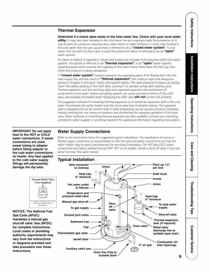
Thermal ExpansionDetermine if a check valve exists in the inlet water line. Check with your local waterutility. It may have been installed in the cold water line as a separate back flow preventer, or itmay be part of a pressure reducing valve, water meter or water softener. A check valve located inthe cold water inlet line can cause what is referred to as a “closed water system”. A coldwater inlet line with no check valve or back flow prevention device is referred to as an “open”water system.
As water is heated, it expands in volume and creates an increase in the pressure within the watersystem. This action is referred to as “thermal expansion”. In an “open” water system,expanding water which exceeds the capacity of the water heater flows back into the city mainwhere the pressure is easily dissipated.
A “closed water system”, however, prevents the expanding water from flowing back into themain supply line, and the result of “thermal expansion” can create a rapid and dangerouspressure increase in the water heater and system piping. This rapid pressure increase can quicklyreach the safety setting of the relief valve, causing it to operate during each heating cycle.Thermal expansion, and the resulting rapid, and repeated expansion and contraction ofcomponents in the water heater and piping system can cause premature failure of the relief valve, and possibly the heater itself. Replacing the relief valve will not correct the problem!
The suggested method of controlling thermal expansion is to install an expansion tank in the coldwater line between the water heater and the check valve (see illustration below). The expansiontank is designed with an air cushion built in that compresses as the system pressure increases,thereby relieving the over pressure condition and eliminating the repeated operation of the reliefvalve. Other methods of controlling thermal expansion are also available. Contact your installingcontractor, water supplier or plumbing inspector for additional information regarding this subject.
Combustion AirInlet Openings
Water Supply ConnectionsRefer to the illustration below for suggested typical installation. The installation of unions orflexible copper connectors is recommended on the hot and cold water connections so that thewater heater may be easily disconnected for servicing if necessary. The HOT and COLD waterconnections are clearly marked and are 3/4” NPT on all models. Install a shut-off valve in the coldwater line near the water heater.
IMPORTANT: Do not applyheat to the HOT or COLDwater connections. If sweatconnections are used,sweat tubing to adapterbefore fitting adapter to the cold water connectionson heater. Any heat appliedto the cold water supplyfittings will permanentlydamage the dip tube.
Typical Installation
Heat trap 6” minimum
Heat trap 6” minimum
Union
Hot water outletto fixtures
Temperature andpressure relief valve
Relief valvedischarge line tosuitable open drain.
To gas supply
Cap
Jacket door
Auxiliary catch pan
Ground joint union
To cold watersupply
6” air gap
Draft hood
Pitch up 1/4”per foot
Union
Thermostatic gas valve
Anode
Vent connectorto chimney
Manual gas shut-off
Shut-off valve
Thermal expansiontank (if required)Sediment trap
Shut-offvalve
Drain Pan Pipe tosuitable drain
NOTICE: The National FuelGas Code (NFGC)mandates a manual gasshut-off valve: See (NFGC)for complete instructions.Local codes or plumbingauthority requirements mayvary from the instructionsor diagrams provided andtake precedent over theseinstructions.
Vacuum Relief Valve(Not Supplied)
If required, install per local codesand valve manufacturer’s
instructions.

Cus
tom
er S
ervi
ceTr
oubl
esho
otin
g Ti
psC
are
and
Cle
anin
gO
pera
ting
Inst
ruct
ions
Inst
alla
tion
Inst
ruct
ions
Saf
ety
Inst
ruct
ions
10
Installing the water heater.A new combination temperature and pressure relief valve, complying with the Standard for Relief Valves andAutomatic Gas Shut-Off Devices for Hot Water Supply Systems, ANSI Z21.22, is supplied and must remain inthe opening provided and marked for the purpose on the water heater. No valve of any type should be installedbetween the relief valve and the tank. Local codes shall govern the installation of relief valves.
Relief ValveThe pressure rating of the relief valve mustnot exceed 150 PSI, the maximum workingpressure of the water heater as markedon the rating plate.
The Btuh rating of the relief valve mustequal or exceed the Btuh input of the waterheater as marked on its rating plate.
Position the outlet of the relief valve above a suitable open drain to eliminatepotential water damage. Piping usedshould be of a type approved for hot waterdistribution.
The discharge line must be no smaller thanthe outlet of the valve and must pitchdownward from the valve to allow completedrainage (by gravity) of the relief valve anddischarge line.
The end of the discharge line should not bethreaded or concealed and should beprotected from freezing. No valve of anytype, restriction or reducer couplingshould be installed in the discharge line.
To Fill the Water HeaterMake certain that drain valve is closed,then open the shut-off valve in the coldwater supply line.
Open each hot water faucet slowly to allowthe air to vent from the water heater andpiping.
A steady flow of water from the hot waterfaucet(s) indicates a full water heater.
WARNING: The tankmust be full of water beforeheater is turned on. Thewater heater warranty doesnot cover damage or failureresulting from operationwith an empty or partiallyempty tank. (Refer to theCertificate of LimitedWarranty for completeterms and conditions.)
!
CondensationCondensation can form on the tank when it is first filled with water.Condensation might also occur with a heavy water draw and very cold inletwater temperatures.
Drops of water falling on the burner canproduce a sizzling or pinging sound.
This condition is not unusual, and willdisappear after the water becomesheated. If, however, the condensationcontinues, examine the piping and fittingsfor possible leaks.
Additional information on this subjectmay be found at www.rheem.comunder “Library,” scroll down to theTechnical Service Bulletins 1400 SeriesSection and choose Bulletin #1402.
Safety Instructions
Installation InstructionsO
perating InstructionsC
are and Cleaning
Troubleshooting TipsC
ustomer S
ervice
11
WARNING: Do not attempt to convert this water heater for use with a different type of gas other than the typeshown on the rating plate. Such conversion could result in hazardous operating conditions.!
Leak TestingThe water heater and its gas connectionsmust be leak tested at normal operatingpressures before it is placed in operation.
Turn on the manual gas shut-offvalve near the water heater.
Use a soapy water solution to testfor leaks at all connections andfittings. Bubbles indicate a gas leakthat must be corrected.
The factory connections to thethermostat should also be leak testedafter the water heater is placed inoperation.
High AltitudeRatings of gas appliances are based on sea level operation and need not bechanged for installations at elevations up to 5,999 feet.
For installations above 5,999 feet, pleasecontact your local distributor or place ofpurchase for a high altitude model.
Pressure Testing the Gas Supply SystemThe water heater and its manual gasshut-off valve must be disconnected fromthe gas supply piping system during anyhigh pressure testing of that system atpressures in excess of 3/8 psi (10.5” w.c.)for natural gas, or 1/2 psi (14” w.c.) for LPgas.
The water heater must be isolated fromthe gas piping system by closing themanual gas shut-off valve during anypressure testing of the gas supply piping at pressures equal to or less than 3/8 psi (10.5” w.c.) for natural gas, or 1/2 psi (14” w.c.) for LP gas.
Gas SupplyThe branch gas supply line to the waterheater should be clean 1/2” black steel pipeor other approved gas piping material.
A ground joint union or ANSI designcertified semi-rigid or flexible gasappliance connector should be installed inthe gas line close to the water heater. TheNational Fuel Gas Code (NFGC) mandatesa manual gas shut-off valve: See (NFGC)for complete instructions.
If flexible connectors are used, themaximum length shall not exceed 36”.
If lever type gas shut-offs are used,they shall be T-Handle type.
Compound used on the threaded joints ofthe gas piping must be of the typeresistant to the action of LP gas. Usecompound sparingly on male threads only.
A sediment trap should be installed at thebottom of the gas line.
Do not use excessive force (over 31.5 ftlbs.) in tightening the pipe joint at the gascontrol (thermostat) inlet, particularly ifteflon pipe compound is used, as the valve body may be damaged.
The inlet gas pressure to the water heatermust not exceed 10.5” w.c. for natural gas,or 14” w.c. for LP gas. For purposes ofinput adjustment, the minimum inlet gaspressure (with main burner on) is shown onthe water heater rating plate. If high orlow gas pressures are present, contactyour gas supplier for correction.
WARNING: Never usean open flame to test forgas leaks, as propertydamage, personal injury or death could result.
!
WARNING: Failure toinstall a water heatersuitable for the altitude atthe location it is intended to serve, can result inimproper operation of theappliance resulting inproperty damage and/or,producing carbon monoxidegas which could result inpersonal injury, or death.
!
Cus
tom
er S
ervi
ceTr
oubl
esho
otin
g Ti
psC
are
and
Cle
anin
gO
pera
ting
Inst
ruct
ions
Inst
alla
tion
Inst
ruct
ions
Saf
ety
Inst
ruct
ions
12
DANGER: Failure toinstall the draft hood andproperly vent the waterheater to the outdoors asoutlined in the Ventingsection of this manual willresult in unsafe operationof the water heater causingbodily injury, explosion, fire or death. To avoid therisk of fire, explosion, orasphyxiation from carbonmonoxide, NEVER operatethe water heater unless it is properly vented andhas adequate air supply for proper operation asoutlined in the Ventingsection of this manual.
!
WARNING: If localcodes require externalapplication of insulationblanket kits themanufacturer’s instructionsincluded with the kit mustbe carefully followed.
!
Installing the water heater.The water heater must be installed with the factory supplied draft hood in place.
VentingVent connectors must be attached to thedraft hood outlet to connect the waterheater to the gas vent or chimney. Thevent connectors must be the same size(diameter) as the draft hood or larger,never smaller.
For proper venting in certain installations a larger vent connector size may beneeded. Consult the Vent Tables inAppendix G of the latest version of theNational Fuel Gas Code (ANSI bookletZ223.1 or NFPA booklet 54.)
Horizontal vent connectors must bepitched upward to the chimney at least1/4” per foot of length. Single wall ventconnectors must be at least 6� fromadjacent unprotected combustiblesurface. Vent joints must be securelyfastened by sheet metal screws or otherapproved method.
Test for spillage at the draft hood reliefopening after 5 minutes of main burneroperation. Use a flame of a match orcandle or smoke. The flame or smokeshould be pulled into the draft hood’s relief opening(s).
Insulation BlanketsInsulation blankets, available to thegeneral public, for external use on gaswater heaters are not necessary. Thepurpose of an insulation blanket is toreduce the standby heat loss encounteredwith storage tank heaters. This waterheater meets or exceeds the NationalAppliance Energy Conservation Actstandards with respect to insulation and standby loss requirements making an insulation blanket unnecessary.
The manufacturer’s warranty does notcover any damage or defect caused byinstallation, attachment or use of any type of energy saving or otherunapproved devices (other than thoseauthorized by the manufacturer) into,onto or in conjunction with the waterheater. The use of unauthorized energysaving devices may shorten the life of thewater heater and may endanger life andproperty.
The manufacturer disclaims anyresponsibility for such loss or injuryresulting from the use of suchunauthorized devices.
CAUTION: If local codes require theapplication of an external insulationblanket to this water heater, pay carefulattention to the following so as not torestrict the proper function andoperation of the water heater:
● Do not cover the operating or warninglabels attached to the water heater orattempt to relocate them on theexterior of insulation blanket.
● Do not apply insulation to the top ofthe water heater. This will interfere withthe safe operation of the draft hood.
● Do not cover the burner access door,jacket door, gas control(thermostat)/gas valve or pressure andtemperature relief valve.
● Do not apply insulation to the bottomof the water heater or the area wherethe combustion air inlet openings arelocated. This area must beunobstructed so as not to restrictcombustion air flow to the burner.
● Inspect the insulation blanket frequentlymaking certain it has not sagged and isrestricting the air flow to thecombustion air inlet openings(perforation holes) located around the lower perimeter of the water heater.This could result in an unsafe operatingcondition.
!
Safety Instructions
Installation InstructionsO
perating InstructionsC
are and Cleaning
Troubleshooting TipsC
ustomer S
ervice
13
Typical vertical piping arrangement Typical horizontal piping arrangement
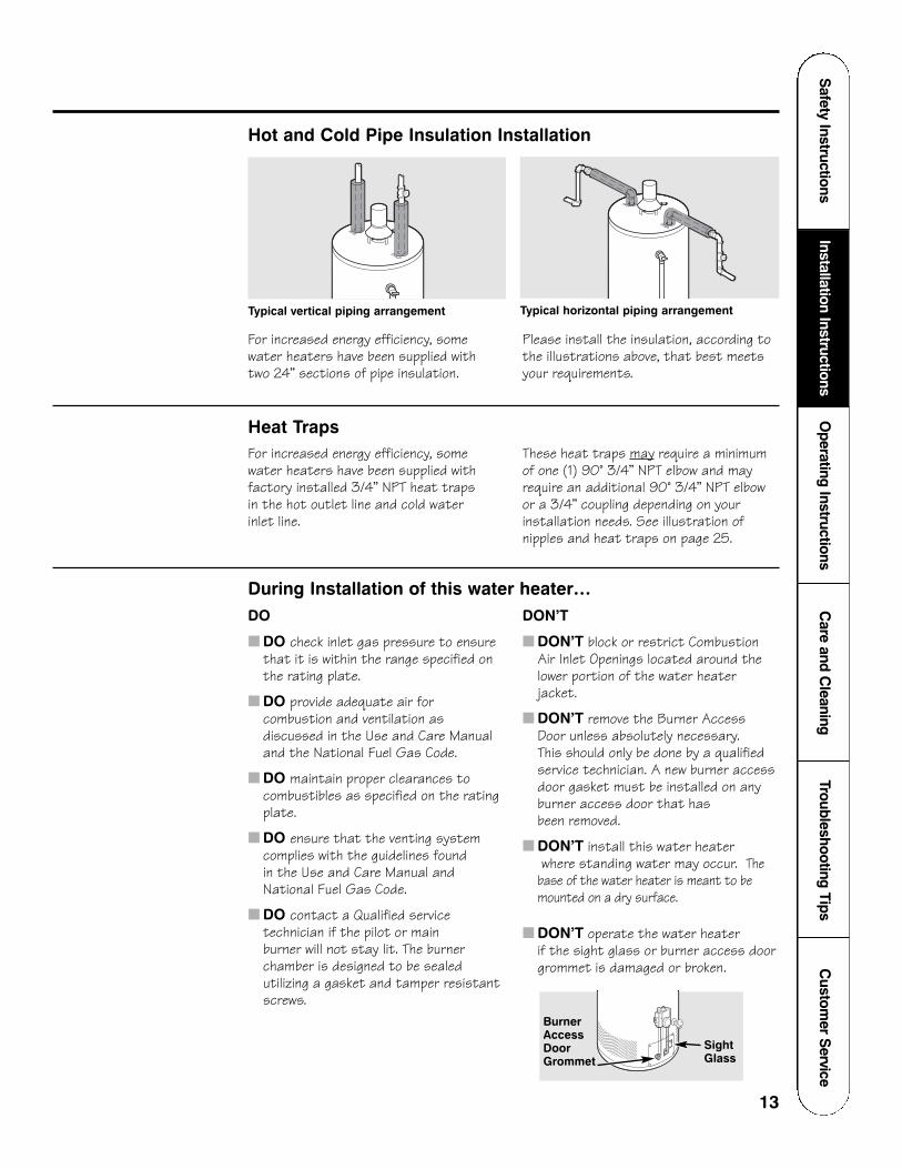
Heat TrapsFor increased energy efficiency, somewater heaters have been supplied withfactory installed 3/4” NPT heat traps in the hot outlet line and cold water inlet line.
These heat traps may require a minimumof one (1) 90° 3/4” NPT elbow and mayrequire an additional 90° 3/4” NPT elbowor a 3/4” coupling depending on yourinstallation needs. See illustration ofnipples and heat traps on page 25.
During Installation of this water heater…DO
■ DO check inlet gas pressure to ensurethat it is within the range specified onthe rating plate.
■ DO provide adequate air forcombustion and ventilation asdiscussed in the Use and Care Manual and the National Fuel Gas Code.
■ DO maintain proper clearances tocombustibles as specified on the ratingplate.
■ DO ensure that the venting systemcomplies with the guidelines found in the Use and Care Manual andNational Fuel Gas Code.
■ DO contact a Qualified servicetechnician if the pilot or main burner will not stay lit. The burnerchamber is designed to be sealedutilizing a gasket and tamper resistantscrews.
DON’T
■ DON’T block or restrict CombustionAir Inlet Openings located around thelower portion of the water heaterjacket.
■ DON’T remove the Burner Access Door unless absolutely necessary. This should only be done by a qualifiedservice technician. A new burner accessdoor gasket must be installed on anyburner access door that has been removed.
■ DON’T install this water heaterwhere standing water may occur. The
base of the water heater is meant to bemounted on a dry surface.
■ DON’T operate the water heater if the sight glass or burner access doorgrommet is damaged or broken.
Hot and Cold Pipe Insulation Installation
For increased energy efficiency, somewater heaters have been supplied with two 24” sections of pipe insulation.
Please install the insulation, according tothe illustrations above, that best meetsyour requirements.
SightGlass
BurnerAccessDoorGrommet
Water Supply■ Water heater completely filled
with water.
■ Air purged from water heater andpiping.
■ Water connections tight and free of leaks.
14
Cus
tom
er S
ervi
ceTr
oubl
esho
otin
g Ti
psC
are
and
Cle
anin
gO
pera
ting
Inst
ruct
ions
Inst
alla
tion
Inst
ruct
ions
Saf
ety
Inst
ruct
ions Installation checklist.
Water Heater Location■ Close to area of vent.
■ Indoors and protected fromfreezing temperatures.
■ Proper clearance from combustiblesurfaces observed and water heaternot installed on carpeted floor.
■ Sufficient fresh air supply forproper operation of water heater.
■ Air supply free of corrosiveelements and flammable vapors.
■ Provisions made to protect areafrom water damage.
■ Sufficient room to service heater.
■ Combustible materials, such asclothing, cleaning materials, rags, etc.clear of the base of the heater.
■ Clearances from combustion airinlet openings observed (see page 7).
Gas Supply■ Gas line equipped with shut-off
valve, union and sediment trap.
■ Approved pipe joint compound used.
■ Soap and water solution used tocheck all connections and fittingsfor possible gas leak.
■ Gas Company inspected installation(if required).
Relief Valve■ Temperature and Pressure Relief
Valve properly installed anddischarge line run to open drain.
■ Discharge line protected fromfreezing.
Venting■ Flue baffle properly hung in top of
heater’s flue.
■ Draft hood properly installed.
■ Vent connector(s) pitched upwardto chimney (1/4” per foot of lengthminimum).
■ Vent connector(s) securelyfastened together with screws.
■ Single wall vent connector(s) atleast 6” from combustible material.
Safety Instructions
Installation InstructionsO
perating InstructionsC
are and Cleaning
Troubleshooting TipsC
ustomer S
ervice
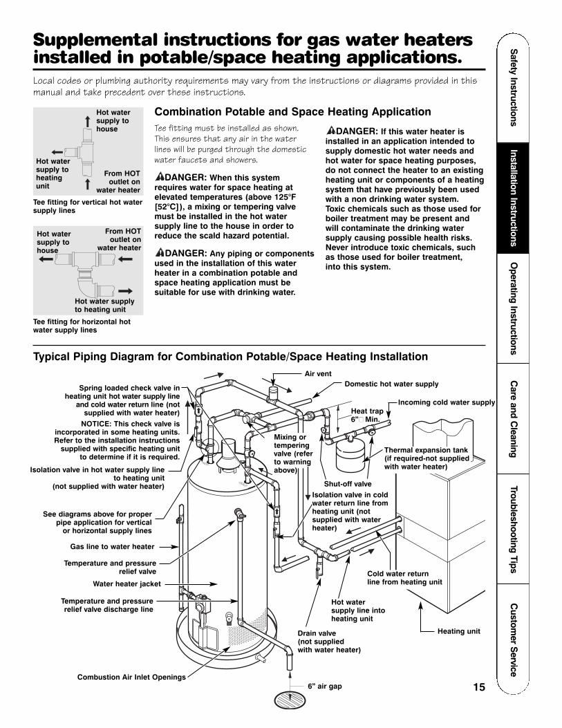
Local codes or plumbing authority requirements may vary from the instructions or diagrams provided in thismanual and take precedent over these instructions.
Tee fitting for vertical hot watersupply lines
Combination Potable and Space Heating ApplicationTee fitting must be installed as shown.This ensures that any air in the waterlines will be purged through the domesticwater faucets and showers.
DANGER: When this systemrequires water for space heating atelevated temperatures (above 125°F[52°C]), a mixing or tempering valvemust be installed in the hot watersupply line to the house in order toreduce the scald hazard potential.
DANGER: Any piping or componentsused in the installation of this waterheater in a combination potable andspace heating application must besuitable for use with drinking water.
DANGER: If this water heater isinstalled in an application intended tosupply domestic hot water needs andhot water for space heating purposes,do not connect the heater to an existingheating unit or components of a heatingsystem that have previously been usedwith a non drinking water system. Toxic chemicals such as those used forboiler treatment may be present and will contaminate the drinking watersupply causing possible health risks.Never introduce toxic chemicals, suchas those used for boiler treatment, into this system.
!
!
!
Tee fitting for horizontal hotwater supply lines
Hot watersupply to house
From HOT outlet on
water heater
From HOT outlet on
water heater
Hot water supply to heatingunit
Hot watersupply tohouse
Hot water supplyto heating unit
RELIEFVALVE COLD
HOT
COLD
HOT
Typical Piping Diagram for Combination Potable/Space Heating Installation
Spring loaded check valve inheating unit hot water supply line
and cold water return line (notsupplied with water heater)
NOTICE: This check valve isincorporated in some heating units.Refer to the installation instructions
supplied with specific heating unitto determine if it is required.
See diagrams above for proper pipe application for vertical
or horizontal supply lines
Gas line to water heater
Cold water returnline from heating unit
Hot watersupply line intoheating unit
Heating unit
Isolation valve in coldwater return line fromheating unit (notsupplied with waterheater)
Water heater jacket
Temperature and pressurerelief valve discharge line
Drain valve (not supplied with water heater)
6” air gap
Isolation valve in hot water supply lineto heating unit
(not supplied with water heater)
Incoming cold water supplyHeat trap6”� Min.
Domestic hot water supply
Shut-off valve
Air vent
Temperature and pressurerelief valve
Combustion Air Inlet Openings15
Supplemental instructions for gas water heatersinstalled in potable/space heating applications.
Mixing ortemperingvalve (referto warningabove)
Thermal expansion tank(if required-not suppliedwith water heater)

Cus
tom
er S
ervi
ceTr
oubl
esho
otin
g Ti
psC
are
and
Cle
anin
gO
pera
ting
Inst
ruct
ions
Inst
alla
tion
Inst
ruct
ions
Saf
ety
Inst
ruct
ions
16
Lighting the water heater. (With SmartWater™ Ignition System)
Before operating this water heater, be sure to read and follow the instructions on the label pictured belowand all other labels on the water heater, as well as the warnings printed in this manual. Failure to do so can result in unsafe operation of the water heater resulting in property damage, personal injury, or death.Should you have any problems reading or following the instructions in this manual, STOP, and get help from aqualified person.

Water Temperature Time To Produce a Serious Burn
120°F More than 5 minutes125°F 11/2 to 2 minutes130°F About 30 seconds135°F About 10 seconds140°F Less than 5 seconds145°F Less than 3 seconds150°F About 11/2 seconds155°F About 1 second
Table courtesy of Shriners Burn Institute
DANGER: Hotter waterincreases the Potential for Hot Water SCALDS.Households with smallchildren, disabled, orelderly persons may requirea 120°F or lower gas control(thermostat) setting toprevent contact with HOTwater.
!
Safety Instructions
Installation InstructionsO
perating InstructionsC
are and Cleaning
Troubleshooting TipsC
ustomer S
ervice
17
Operating the water heater.CAUTION: Hydrogen gas can be produced in a hot water system served by this water heater that has not been
used for a long period of time (generally two weeks or more). HYDROGEN GAS IS EXTREMELY FLAMMABLE!! Todissipate such gas and to reduce risk of injury, it is recommended that the hot water faucet be opened for severalminutes at the kitchen sink before using any electrical appliance connected to the hot water system. If hydrogen ispresent, there will be an unusual sound such as air escaping through the pipe as the water begins to flow. Do notsmoke or use an open flame near the faucet at the time it is open.
!
Safety PrecautionsDo turn off manual gas shut-off valve if water heaterhas been subjected to over heating, fire, flood,physical damage or if the gas supply fails to shut off.
Do Not turn on water heater unless it is completelyfilled with water.
Do Not turn on water heater if cold water supplyshut-off valve is closed.
Do Not allow combustible materials such asnewspaper, rags or mops to accumulate near water heater.
Do Not store or use gasoline or other flammablevapors and liquids, such as adhesives or paintthinner, in vicinity of this or any other appliance. If such flammables must be used, open doors andwindows for ventilation, and all gas burningappliances in the vicinity should be shut off includingtheir pilot burners, to avoid vapors lighting.
NOTICE: Flammable vapors can be drawn by air currentsfrom surrounding areas to the water heater.
If there is any difficulty in understanding or followingthe Operating Instructions or the Care and Cleaningsection, it is recommended that a qualified person orserviceman perform the work.
Water Temperature SettingThe temperature of the water in the waterheater can be regulated by setting thetemperature dial on the front of the gascontrol (thermostat).
Safety and energy conservation arefactors to be considered when selectingthe water temperature setting of thewater heater’s gas control(thermostat(s)). The lower thetemperature setting, the greater thesavings in energy and operating costs.
To comply with safety regulations the gascontrol (thermostat) was set at itslowest setting before the water heaterwas shipped from the factory. Therecommended starting point temperatureis 120°F.
Water temperatures above 125°F cancause severe burns or death fromscalding. Be sure to read and follow thewarnings outlined in this manual and onthe label located on the water heater nearthe gas control (thermostat).
Mixing valves are available for reducingpoint of use water temperature by mixinghot and cold water in branch water lines.Contact a licensed plumber or the localplumbing authority for further information.(See page 4 for more details).
The chart below may be used as a guide indetermining the proper water temperaturefor your home.
Time/Temperature Relationship in Scalds
18
Cus
tom
er S
ervi
ceTr
oubl
esho
otin
g Ti
psC
are
and
Cle
anin
gO
pera
ting
Inst
ruct
ions
Inst
alla
tion
Inst
ruct
ions
Saf
ety
Inst
ruct
ions
Temperature dial
(Temperatures are approximate)
WARMV
AC
ATION
HO
T CAUTION
THE RISK OF SCALDIN
JUR
Y
WATE R IN CRE
AS
ES
H O T TE
R
W A R N I N GREAD ALL INSTRUCTIONSBEFORE LIGHTING
130°F
Gas cock knob
120°F
140°F
150°F
160°F
110°F
100°F
90°F
80°F
70°F
60°F
Red Button
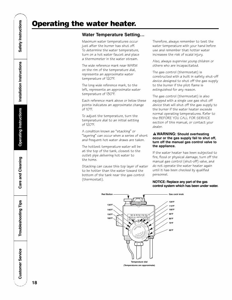
Operating the water heater.Water Temperature Setting…Maximum water temperatures occur just after the burner has shut off. To determine the water temperature, turn on a hot water faucet and place a thermometer in the water stream.
The wide reference mark near WARM on the rim of the temperature dial,represents an approximate watertemperature of 120°F.
The long wide reference mark, to the left, represents an approximate watertemperature of 130°F.
Each reference mark above or below thesepoints indicates an approximate change of 10°F.
To adjust the temperature, turn thetemperature dial to an initial setting of 120°F.
A condition known as “stacking” or“layering” can occur when a series of shortand frequent hot water draws are taken.
The hottest temperature water will be at the top of the tank, closest to theoutlet pipe delivering hot water to the home.
Stacking can cause this top layer of waterto be hotter than the water toward thebottom of the tank near the gas control(thermostat).
Therefore, always remember to test thewater temperature with your hand beforeuse and remember that hotter waterincreases the risk of scald injury.
Also, always supervise young children orothers who are incapacitated.
The gas control (thermostat) isconstructed with a built in safety shut-offdevice designed to shut off the gas supplyto the burner if the pilot flame isextinguished for any reason.
The gas control (thermostat) is alsoequipped with a single use gas shut offdevice that will shut off the gas supply tothe burner if the water heater exceedsnormal operating temperatures. Refer tothe BEFORE YOU CALL FOR SERVICEsection of this manual, or contact yourdealer.
WARNING: Should overheatingoccur or the gas supply fail to shut off,turn off the manual gas control valve tothe appliance.
If the water heater has been subjected tofire, flood or physical damage, turn off themanual gas control (shut-off) valve, anddo not operate the water heater againuntil it has been checked by qualifiedpersonnel.
NOTICE: Replace any part of the gascontrol system which has been under water.
!
19
Safety Instructions
Installation InstructionsO
perating InstructionsC
are and Cleaning
Troubleshooting TipsC
ustomer S
erviceCare and cleaning of the water heater.
Draining the Water HeaterCAUTION: Shut off gas to the water
heater at the gas control (thermostat)gas cock or manual shut-off valvebefore draining water.
DANGER: Before manually operatingthe temperature and pressure reliefvalve, make certain no one will beexposed to the hot water released by thevalve. The water drained from the tankmay be hot enough to present a scaldhazard and should be directed to asuitable drain to prevent injury ordamage.
In order to drain the water heater, turn offthe cold water supply. Open a hot waterfaucet or lift the handle on the relief valveto admit air to the tank.
Attach a garden hose to the drain valve on the water heater and direct the stream of water to a drain. Open the valve.
!
!
DANGER: Combustiblematerials, such as clothing,cleaning materials, orflammable liquids, etc.,must not be placed againstor next to the water heater.
! HousekeepingVisually inspect pilot burner and relight ifnecessary.
To ensure sufficient ventilation andcombustion air supply, proper clearancesmust be maintained.
When installed in a closet, DO NOTblock or obstruct any of the combustionair inlet openings located around theperimeter of the water heater. Aminimum of 1” is required betweenthese combustion air inlet openings andany obstruction.
DANGER: Beforemanually operating therelief valve, make certainno one will be exposed tothe danger of the hot waterreleased by the valve. Thewater may be hot enoughto create a scald hazard.The water should bereleased into a suitabledrain to prevent injury orproperty damage.
DANGER: Hotter waterincreases the potential forHot Water Scalds.
DANGER: Failure toperform the recommendedRoutine PreventativeMaintenance can harm theproper operation of thiswater heater, which cancause carbon monoxidedangers, excessive hotwater temperatures andother potentially hazardousconditions
!
!
! Routine Preventative MaintenanceProperly maintained, your water heater willprovide years of dependable trouble-freeservice. It is recommended that a periodic inspectionof the gas control (thermostat), burner,relief valve, internal flue-way and ventingsystem should be made by service personnelqualified in gas appliance repair.It is suggested that a routine preventativemaintenance program be established andfollowed by the user. At least once a year, lift and release thelever handle on the temperature pressurerelief valve, located near the top of the waterheater, to make certain the valve operatesfreely. Allow several gallons to flush throughthe discharge line to an open drain.NOTICE: If the temperature and pressure relief valve on the hot waterheater discharges periodically, this maybe due to thermal expansion in a closedwater system. Contact the water supplieror your plumbing contractor on how tocorrect this. DO NOT plug the relief valve outlet.A water heater’s tank can act as a setlingbasin for solids suspended in the water. It istherefore not uncommon for hard waterdeposits to accumulate in the bottom of thetank. If allowed to accumulate, these solidscan cover the gas control (thermostat)sensors, causing the sensors to operateerratically.
Because accumulated solids can prevent thegas control (thermostat) sensors fromaccurately reading the water temperature,the water at the fixture can be hotter thanthe gas control (thermostat) dial setting. Itis suggested that a few quarts of water bedrained from the water heater’s tank everymonth to clean the tank of these deposits.Rapid closing of faucets or solenoid valves inautomatic water using appliances can causea banging noise heard in a water pipe.Strategically located risers in the water pipesystem or water hammer arresting devicescan be used to minimize the problem.The anode rod should be removed from thewater heater’s tank annually for inspectionand replaced when more than 6”� of corewire is exposed at either end of the rod. Make sure the cold water supply is turnedoff before removing anode rod.This water heater incorporates acombustion shut off device that shuts the operation of the water heater down if undesirable combustion conditions occur.Such as the presence of flammable vaporsor blockage of the combustion air inletopenings. Please contact a Qualified Service Technician if this occurs.

Cus
tom
er S
ervi
ceTr
oubl
esho
otin
g Ti
psC
are
and
Cle
anin
gO
pera
ting
Inst
ruct
ions
Inst
alla
tion
Inst
ruct
ions
Saf
ety
Inst
ruct
ions
Proper burner and pilot flamepattern
20
Care and cleaning of the water heater.Venting System InspectionThe water heater’s internal flue must beinspected annually to be certain it is cleanby removing the draft hood and flue baffle.
When reinstalling the flue baffle makecertain it is hung securely by its hanger at the top of the flue way.
Reinstall the draft hood.
Inspect the gas venting system and the chimney.
Make certain the vent connector from the draft hood to the chimney is properly positioned and securelyattached.
If after inspection of the vent system you found sooting or deterioration call the local gas utility to correct theproblem and clean the flue, or replace the flue, flue baffle, and venting system beforeresuming operation of the water heater.
Test for spillage at the draft hood reliefopening after 5 minutes of burneroperation. Use a flame of a match orcandle or smoke.
NOTICE: Refer to theHydrogen Gas Caution inthe Operating Instructions.
Vacation and Extended Shut-DownIf the water heater is to remain idle for anextended period of time, the power andwater to the appliance should be turnedoff to conserve energy and prevent a build-up of dangerous hydrogen gas.
The water heater and piping should bedrained if they might be subjected tofreezing temperatures.
After a long shut-down period, the waterheater’s operation and controls should bechecked by qualified service personnel.Make certain the water heater iscompletely filled again before placing it in operation.
NOTICE: Do not remove theanode rod from the waterheater’s tank, except forinspection and/orreplacement, as operationwith the anode rod removedwill greatly shorten the life ofthe glass lined tank and willexclude warranty coverage.
Anode RodThis water heater is equipped with ananode rod designed to prolong the life of the glass lined tank. The anode rod is slowly consumed, thereby eliminating or minimizing corrosion of the glass lined tank.
Water sometimes contains a high sulfateand/or mineral content and together withcathodic protection process can producea hydrogen sulfide, or rotten egg odor inthe heated water. Chlorination of thewater supply should minimize the problem.
Burner InspectionVisually inspect the pilot and main burnersannually.
Through the sight glass, inspect the pilotburner flame with main burner off andinspect the main burner while firing.
If any unusual burner operation is noted,the water heater should be shut off until qualified service assistance can be obtained.
CAUTION: For your safety, cleaningof the main burner must be performedonly by qualified service personnel. Theburner chamber is a sealed area. If the burner access door is removed,the burner access door gasket must bereplaced.
For cleaning, remove the burner from thewater heater. A vacuum cleaner can beused on the burner and floor shield insidethe water heater.
The burner can also be cleaned byscrubbing with mild detergent.
!
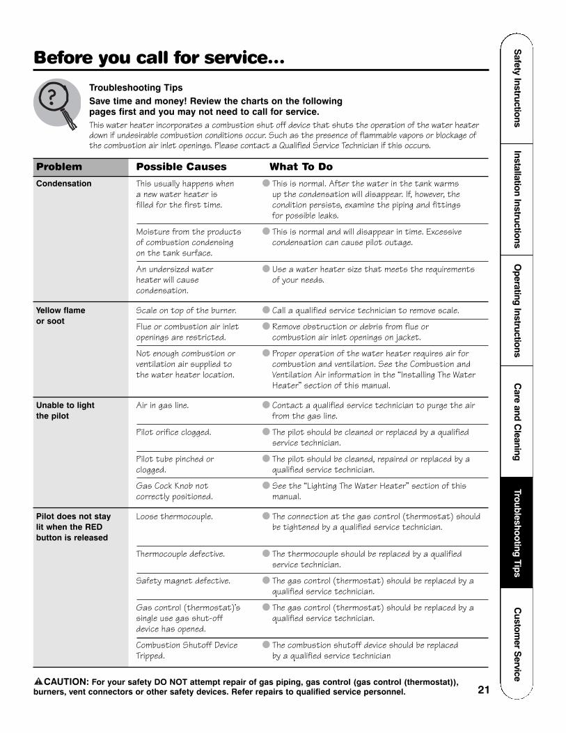
Problem Possible Causes What To Do
Condensation This usually happens when ● This is normal. After the water in the tank warms a new water heater is up the condensation will disappear. If, however, the filled for the first time. condition persists, examine the piping and fittings
for possible leaks.
Moisture from the products ● This is normal and will disappear in time. Excessive of combustion condensing condensation can cause pilot outage.on the tank surface.
An undersized water ● Use a water heater size that meets the requirements heater will cause of your needs.condensation.
Yellow flame Scale on top of the burner. ● Call a qualified service technician to remove scale.or soot Flue or combustion air inlet ● Remove obstruction or debris from flue or
openings are restricted. combustion air inlet openings on jacket.
Not enough combustion or ● Proper operation of the water heater requires air for ventilation air supplied to combustion and ventilation. See the Combustion andthe water heater location. Ventilation Air information in the “Installing The Water
Heater” section of this manual.
Unable to light Air in gas line. ● Contact a qualified service technician to purge the airthe pilot from the gas line.
Pilot orifice clogged. ● The pilot should be cleaned or replaced by a qualified service technician.
Pilot tube pinched or ● The pilot should be cleaned, repaired or replaced by a clogged. qualified service technician.
Gas Cock Knob not ● See the “Lighting The Water Heater” section of this correctly positioned. manual.
Pilot does not stay Loose thermocouple. ● The connection at the gas control (thermostat) should lit when the RED be tightened by a qualified service technician.button is released
Thermocouple defective. ● The thermocouple should be replaced by a qualified service technician.
Safety magnet defective. ● The gas control (thermostat) should be replaced by a qualified service technician.
Gas control (thermostat)’s ● The gas control (thermostat) should be replaced by a single use gas shut-off qualified service technician.device has opened.
Combustion Shutoff Device ● The combustion shutoff device should be replaced Tripped. by a qualified service technician
CAUTION: For your safety DO NOT attempt repair of gas piping, gas control (gas control (thermostat)),burners, vent connectors or other safety devices. Refer repairs to qualified service personnel.!
Troubleshooting TipsSave time and money! Review the charts on the following pages first and you may not need to call for service. This water heater incorporates a combustion shut off device that shuts the operation of the water heaterdown if undesirable combustion conditions occur. Such as the presence of flammable vapors or blockage ofthe combustion air inlet openings. Please contact a Qualified Service Technician if this occurs.
Safety Instructions
Installation InstructionsO
perating InstructionsC
are and Cleaning
Troubleshooting TipsC
ustomer S
ervice
21
Before you call for service…
22
Cus
tom
er S
ervi
ceTr
oubl
esho
otin
g Ti
psC
are
and
Cle
anin
gO
pera
ting
Inst
ruct
ions
Inst
alla
tion
Inst
ruct
ions
Saf
ety
Inst
ruct
ions
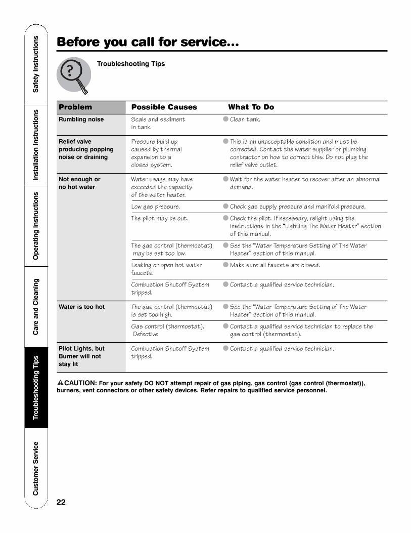
Problem Possible Causes What To Do
Rumbling noise Scale and sediment ● Clean tank.in tank.
Relief valve Pressure build up ● This is an unacceptable condition and must be producing popping caused by thermal corrected. Contact the water supplier or plumbing noise or draining expansion to a contractor on how to correct this. Do not plug the
closed system. relief valve outlet.
Not enough or Water usage may have ● Wait for the water heater to recover after an abnormal no hot water exceeded the capacity demand.
of the water heater.
Low gas pressure. ● Check gas supply pressure and manifold pressure.
The pilot may be out. ● Check the pilot. If necessary, relight using the instructions in the “Lighting The Water Heater” section of this manual.
The gas control (thermostat) ● See the “Water Temperature Setting of The Water may be set too low. Heater” section of this manual.
Leaking or open hot water ● Make sure all faucets are closed.faucets.
Combustion Shutoff System ● Contact a qualified service technician.tripped.
Water is too hot The gas control (thermostat) ● See the “Water Temperature Setting of The Water is set too high. Heater” section of this manual.
Gas control (thermostat). ● Contact a qualified service technician to replace the Defective gas control (thermostat).
Pilot Lights, but Combustion Shutoff System ● Contact a qualified service technician. Burner will not tripped.stay lit
CAUTION: For your safety DO NOT attempt repair of gas piping, gas control (gas control (thermostat)),burners, vent connectors or other safety devices. Refer repairs to qualified service personnel.!
Troubleshooting Tips
Before you call for service…
Safety Instructions
Installation InstructionsO
perating InstructionsC
are and Cleaning
Troubleshooting TipsC
ustomer S
ervice
23
Notes.
Cus
tom
er S
ervi
ceTr
oubl
esho
otin
g Ti
psC
are
and
Cle
anin
gO
pera
ting
Inst
ruct
ions
Inst
alla
tion
Inst
ruct
ions
Saf
ety
Inst
ruct
ions
24
Notes.
Safety Instructions
Installation InstructionsO
perating InstructionsC
are and Cleaning
Troubleshooting TipsC
ustomer S
ervice
25
Draft hood
Temperature andpressure relief valve
* Burner Access Door Gasket
Flue baffle andhanger
Anode rodDip tube
Dip tube gasket
* Burner
* Burner Orifice
Gas Control (Thermostat)
Piezo Ignitor Striker
Mounting BracketDrain Valve
* Pilot Burner andPiezo electrode
* Thermocouple
* Pilot Supply Tube
* Piezo Ignitor Wire
* Burner Access Door Grommet
Jacket Door
* Sight Glass
* Burner Access Door
* Burner Supply Tube
The kit provides extra speed clipsand tamper resistant screws.
**Not supplied with all models.
*Burner Assembly Kit**Heat Trap
**Nipple
**Heat Trap
**Nipple
Replacement parts.For 30, 40 and 50 gallon models using natural or LP gas.
Instructions For Placing a Parts OrderTo place orders using a Visa/MasterCard call 800-431-1549.
All parts orders should include:
The model and serial number of thewater heater from the rating plate.
Specify type of gas (natural or LP)as marked on the rating plate.
Part description (as noted below)and number of parts desired.
CAUTION: For your safety DO NOT attempt repair of gas piping,gas control (thermostat), burners, ventconnectors or other safety devices.Refer repairs to qualified servicepersonnel.
!
Cus
tom
er S
ervi
ceTr
oubl
esho
otin
g Ti
psC
are
and
Cle
anin
gO
pera
ting
Inst
ruct
ions
Inst
alla
tion
Inst
ruct
ions
Saf
ety
Inst
ruct
ions
26
If you need service…
Should you have any questions about your new water heater, or if it requires adjustment, repair, or routine maintenance, it is suggested that you first contact your installer, plumbingcontractor or previously agreed upon service agency. In the event the firm has moved, or isunavailable, refer to the telephone directory, commercial listings or local utility for qualified service assistance.
Should your problem not be solved to your complete satisfaction, you should then contact the Manufacturer’s National Service Department at the following address:
2600 Gunter Park DriveMontgomery, AL 36109-1413
When contacting the manufacturer, the following information will be requested:
Model and serial number of the water heater as shown on the rating plate attached to the jacket of the heater.
Address where the water heater is located and physical location.
Name and address of installer and any service agency who performed service on the water heater.
Date of original installation and dates any service work was performed.
Details of the problems as you can best describe them.
List of people, with dates, who have been contacted regarding your problem.
If you need a manual in Spanish, please refer to our website: www.rheem.com.
Si requiere de un manual de uso y cuidado en espanol, usted puede obtanerlo enwww.rheem.com.
Rheem Manufacturing CompanyWarranty Registration DepartmentP.O. Box 34070Louisville, KY 40232-4070
Please place in envelope and mail to:
✁ Cut here
✁Cut here
27

28
✁ Cut here
Consumer Product Ownership Registration
Follow these three steps to protect your new appliance investment:
If you require service, call 800-431-1549.
1 2 3Model Number Serial Number
Consumer Product Ownership RegistrationModel NumberWater Heater Serial Number
Important
Today!
FirstName
Mr. ■■ Ms. ■■ Mrs. ■■ Miss ■■
StreetAddress
City
StateDate Placed
In UseMonth Day Year
ZipCode
Apt. #
LastName
PhoneNumber
_ _
Complete and mailthis ConsumerProduct OwnershipRegistration today.
After mailing theregistration below,store this documentin a safe place. Itcontains informationyou will need shouldyou require service.
Read your Use andCare Manualcarefully. It will helpyou operate yournew applianceproperly.
✁Cut here
NOTICE: Failure to complete and return this card does not diminish your limited warranty rights.