gas storage is the supply and demand relief valve sources: doe and simmons & company...
Post on 21-Dec-2015
215 views
TRANSCRIPT

Gas Storage Is The Supply And Demand Relief Valve
Sources: DOE and Simmons & Company International.

Gas Laws• Most substances are relatively easy to specify as to
quantity. A pound of a solid material is definitive. A gallon of a liquid is almost definitive, with only a minor variation due to temperature and pressure. A cubic foot of gas, however, is not at all definitive. This is because gases are compressible. They are greatly affected by temperature and pressure.
• Pressure may be measured by several different instruments. Some of these are pressure gauges, liquid filled manometers, and the various types of pressure transducers.
Pressure Measurement
• All of these devices have one common characteristic they are actually measuring a differential pressure. An example is the liquid-filled manometer. One leg of the manometer is connected to the pressure being measured. The other leg is open to the atmosphere (or to some other pressure). When one leg is open to the atmosphere, the device is measuring the differential pressure between the pressure vessel and the atmosphere.
Temperature Measurement
• There are several temperature scales. These include Celsius, Fahren heit, and Ranier, which beer makers use .The scales were patterned to provide a convenience for everyday living. Although often obscure, there was some logic to the scale development. The Celsius scale took the boiling point of water as one point and the freezing point of water as another and divided the distance between them into 100 degrees.

The Effect of Pressure on Gas Volume
• When pressure is applied to a given quantity of gas, the volume shrinks, which is illustrated in Figure -1. In the first diagram, gas is confined in a cylinder with a sliding piston. Sufficient weight is on the piston to produce a pressure of 35 psig and the gas volume is 10 cubic feet. The second diagram shows the same vessel when more weight has been added to the piston. The pressure is now 85 psig and the volume is 5 cubic feet.

Figure 1. The effect of pressure on gas volume at constant temperature
• Boyle's law states that if a gas is at constant temperature, its volume is inversely proportional to the pressure, or
•P1 x V1= P2 x V2 ……………………………..(1)
• A casual inspection of Figure 4-1 would tend to indicate that the gas in the cylinder does not follow Boyle's law. It must be remembered, however, that the pressures of 35 psig and 85 psig are gauge pressures or differen tial pressures with the atmosphere. When the atmospheric pressure (approximately 15 psia) is added to the gauge pressures, the result is 50 psia and 100 psia. The gas volumes and the absolute pressures are then inversely proportional.

The Effect of Temperature on Gas Volume• When the temperature of a quantity of gas is raised, the
volume of the gas increases, which is illustrated in Figure -2. In the first diagram the gas temperature is 60°F and the gas volume is 5 cubic feet. The second diagram shows that when the temperature is raised to 580°F, the gas volume doubles to 10 cubic feet, the pressure remaining constant.
• Charles' law states that the volume of a gas is directly proportional to the temperature of the gas when the pressure remains constant or:
• V1/T1 =V2/T2 ……………………………………..(2)• Again, the diagrams in Figure -2 do not seem to support this
law until it is remembered that the temperatures must be on an absolute scale. To convert the Fahrenheit temperatures to absolute. temperatures (degrees Rankine), 460 must be added to the Fahrenheit values. When this is done, the two temperatures become 520 and 1040° Rankine, respectively. With these values, Equation 4-2 does hold for Figure -2.

Figure -2. The effect of temperature on gas volume at constant pressure

Ideal Gas Law
• The laws of Boyle and Charles may be combined into a single equation:
(3)
• This is called the ideal gas law. This law also may be expressed in a diff erent form by making the following derivation where the "s" subscript denotes standard conditions:
(4)
P1xV1 = P2x V2
T1 T2
PxV = Psx Vs
T Ts

• the ideal gas law is:P V = n R T (5)
Different values of R are given in the following table:

Compressibility Factors
• The ideal gas laws work well at relatively low pressures and relatively high temperatures. When the pressure and temperature depart from these ranges, significant error can result from the use of the ideal gas laws.
• When the compressibility factor is incorporated into the ideal gas law equation, the result is:
• PxV = nxZxRxT (6)• where Z is the compressibility factor determined by
whatever method is appropriate.

Approximations• The compressibility factor equations are intended to be used
with natural gases with a wide range of properties and exposed to a wide range of conditions. By necessity, these equations are quite sophisticated, lengthy, and require considerable computer effort. In a given storage reservoir, there is little variation in temperature and the range of pressure variations is relatively small. Furthermore, the composition of the gas will not vary dramatically with time. For this type of situation an approximate equation for compressibility factors is appropriate.
• The total gas in place in the reservoir should be a straight line function of the pressure divided by the compressibility factor, or:

GIP = a + b x P (7) ZWhere:GIP = total gas in place P = pressure in psia Z = compressibility factor a = constant b = constantThe compressibility factor can be computed in an approximate manner for the limitations imposed above by the following form of equation:

Z = c + d x P (8) Where:c and d are constants By combining these two equations the total gas in place in the reservoir may be calculated as a function of the pressure: (9)
This equation can be used to estimate total gas in place in the reservoir with reasonable accuracy. Appendix A shows how to evaluate the con stants a, b, c, and d for a specific reservoir. It should be emphasized that Equations (8) and (9) should be used only where there is a limited range of variation in pressure, temperature, and gas composition.

The Components of a Gas Storage Facility
• A storage facility usually consists of some of the following components:
• Underground reservoir• Gathering system• Injection wells• Compressor facility• Withdrawal wells• Metering facility• Injection-withdrawal wells• Dehydrator• Observation wells• Transmission line to the pipeline

Schematic Representation of Components of a Gas Storage Facility

Underground Reservoirs
Underground reservoirs are geological structures that have unique features. There is a porous medium having some degree of permeability. •The porosity allows natural gas to be contained within the medium. •The permeability allows the gas to move from point to point within the medium. •There is almost always an impermeable layer overlying the porous medium. This impermeable layer is usually curved or dome shaped and prevents the gas contained in the porous medium from rising to the surface of the ground. The curve of the cap rock may also prevent the lateral movement of the gas outside the porous medium. •Permeability is the ability of gas (or other fluid) to flow through a medium with a given pressure drop.

•The greater the permeability is, the greater the flow is for a given pressure drop. Because flow in a permeable medium requires pressure drop, the pressure in a reservoir that is being produced will vary within the reservoir. At the well bore the pressure will be the lowest when gas is being withdrawn. Conversely, the pressure will be highest at the well bore when gas is being injected into the reservoir. •Underground reservoirs may be classified into two general types: •1-volumetric reservoirs and •2-water drive reservoirs. -The volumetric type is sealed on all sides by impermeable rock and behaves like a pressure vessel. This structural seal by geologic characteristics keeps its size and shape con stant.

• The water drive reservoir is sealed on the top and sides by impermeable rock but is sealed on the bottom by water. This type of reservoir may be thought of as a bucket inverted in a body of water.
• As more gas is introduced into the bucket, water is forced out and the size of the gas bubble inside the bucket increases.
• Figures (4) and (5) illustrate in a simple manner the way in which the two reservoir types behave. In Figure (4), the volume of the reservoir pores that contain the gas is constant.
• As the quantity of gas in the reservoir is doubled, the absolute pressure doubles. This simplified example assumes constant temperature and ideal gas laws. In Figure (5), as the quantity of gas is doubled, the volume of the reservoir pores containing the gas increases due to some of the water being pushed back.
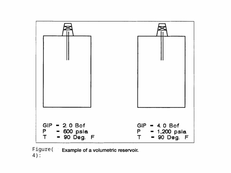
Figure(4):

Figure(5):

• This creates a larger storage volume. For this reason the pressure does not rise as rapidly as in the case of the volumetric structure. The increase in pressure is only 75 percent, as opposed to 100 percent in the volumetric case. As the gas is produced from fields that have a water-drive reservoir, the decreased reservoir pressure allows the water to encroach and slowly fill the reservoir.
• At depletion, the reservoir may be completely filled with water except for a small gas cap. If the field is converted to a storage facility, new storage wells may be drilled. These new wells will usually be large bore, high capacity wells as opposed to the relatively small bore wells that were used for original production. These wells have the capability of injecting gas at a high rate. Care must be used when this is the case.

• Ideally, when gas is re-injected into a reservoir filled with water, the gas would displace the water and maintain a level, horizontal gas-water interface.
• If this were the case, gas could be re-injected at a high rate. Unfortunately, the gas has a tendency to override the water and travel along the top surface of the reservoir.
• This can result in a gas-water interface that is highly sloped and runs down-structure. The more level the cap rock is and the faster the rate of injection, the more pronounced this effect is.

• Figure (6) shows an example of this gas override. There is the possibility that gas may travel along the top of the reservoir and reach a low point water seal. If this occurs, gas may be lost from the storage reservoir and be transmitted to an adjacent reservoir.
• If the adjacent reservoir is not owned as part of the storage facility, the gas may be lost forever. Therefore it may be necessary to inject at a relatively low rate during the early stages of reservoir development. Observation wells also may be of help in monitoring the extent and shape of the gas-water interface.

Figure(6):

Wells• Wells are used to transfer gas into and out of the storage
reservoir. Combination injection-withdrawal wells are the most common type because they are the most economical. They are used to either inject or withdraw gas.
• Due to the individual reservoir characteristics, it may not be feasible or desirable to inject or withdraw in a particular portion of the reservoir. This might be due to a desire to control water influx, the shape of the gas bubble, or other reasons.
• In those cases there may be one or two wells that are used for only injection or only withdrawal. The injection-withdrawal wells are usually large-bore wells, much larger in diameter than normal producing wells.
• This increased diameter is to give the increased deliverability needed from storage wells.
• Observation wells are used to monitor water migration in a reservoir. There might be a "saddle" or low point in the structure where gas could escape if it reached there.
• An observation well might be placed on the gas bubble side of the saddle to monitor whether there is gas or water at that point.
• Observation wells can be of small diameter. Sometimes a dry hole or unsatisfactory injection well will be converted into an observation well.

• The following equation may be used to calculate the flow rate for a single well during withdrawal from the reservoir:
Q= C x (PSIS2 – PFs
2)n
Where:Q= withdrawal flow ratePSIS= shut in surface pressure
PFS= flowing surface pressure
C= coefficient determined by testn= coefficient determined by test

• One way to accommodate fluctuating demand would
be to build a pipeline from the gas fields large
enough to supply the greatest amount of gas that
would be needed in mid winter. In the summer,
pipeline pressure could be reduced so that gas would
flow at a fraction of the pipeline capacity. This,
however, would be an inefficient use of an expensive
facility.

• Instead, the pipeline companies usually have
operated their pipelines at full capacity throughout
the years; in summer time, they (or the gas
distributing companies] have sold the excess gas at
reduced prices to manufacturers and other industrial
users. In the winter when the gas was needed for
heating, the industrial users switched to other fuels
such as oil or coal.
• Underground storage is usually a good means of meeting peak demands, but it must have a suitable underground structure close to the point of consumption if it is to be an economic proposition.
• Natural gas storage in pipelines• Underground natural gas storage in depleted fields (if these
are available)• Underground natural gas storage in aquifers• Natural gas storage under high pressure in steel reservoirs• Natural gas storage by natural gas solution in propane


• Liquefied natural gas (LNG) storage• The storage unit cost for the various storage systems are
(1974 dollars) (Medici):• Underground storage in depleted fields: $0.70 to $1.75 per m3
• Gas storage in water layers: $1.88 per m3
• Gas storage in salt formations: $5.00 per m3
• LNG storage: $460.00 per m3
• Gas storage in propane: $1,130.00 per m3
• Natural gas storage in pipeline at 1,600 psia: $1,700.00 per m3
•The demand for natural gas varies from hour to hour and day to day. The largest demand usually occurs at 6:00 p.m. on a cold winter day.
• The rate at which gas is used plotted against the time of day is termed the load curve. A typical load curve, showing delivery of gas during a cold day, is illustrated in Fig. 13.2. The average rate for this day is 212,000 cu ft, the maximum rate being 65% above the average and the minimum rate being 61% below the average.
• The characteristic data for a natural gas storage plant are useful storage capacity of the reservoir, maximum volume of natural gas to be stored and extracted from it, and the related gas pressures. These data are determined with reference to load diagrams at daily, weekly, and yearly intervals, in relation to the gas trunk line along which it is planned to insert the storage plant.

Natural Gas Storage in Pipelines
• Grid pipeline systems are often used as temporary natural gas stor age facilities. Intermediate natural gas compression stations enable the pressure in the main pipeline system to be raised appreciably (from 300 to 1,000 psia with a corresponding rise in the amount of gas stored in the pipes.. Quantities of natural gas which are not required at that moment by utilities are in this way stored in pipeline system.. When natural gas demand increases, then stored gas can be supplied to utilities by lowering the pressure in the pipeline system (from 1,000 to 350 psia as a typical example). Pipeline storage is very useful for compensating peaks in demand which have time intervals of a few hours.

Storage Capacity of Simple Pipelines
• To determine the storage capacity of a pipeline, an expression must be developed for the total line content which will account for the variable pressure conditions at all points along the line. Having such an expression, the total content under the packed and unpacked conditions may be computed and the storage capacity ascertained by taking their difference.. A pipeline is packed when withdrawal from the line is a minimum and when, for a constant supply of gas, the discharge pressure is a maximum. The flow rate for packed condition is a mean between the minimum and average rates for the day. Similarly, a pipe line is unpacked when withdrawals are a maximum and pressure is a minimum for a constant supply of gas to the line.

• Using this definition of storage capacity and the Weymouth equation (Chapter 7), an expression can be derived that consider the variation in compressibility of the gas with pressure. Let p be the absolute pres sure at any point on the line. Then for any flow condition and length of line L, the Weymouth flow formula becomes:


Equation 13.6 gives the quantity of gas measured at base conditions stored in the pipeline for any given flow condition..To determine the storage capactty of a simple pipeline, the pressures at both ends are determined by both packed and unpackdd flow condi tions. The difference betwenn the two quantities is the storage capacity of the pipeline.
Example 13.1. • The average flow condition through a 10-in. pipeline 50 miles
long is 36 MMefd. The gas is delivered at a pressure of 50 psia. Minimum flow is at the rate of 10 MMefd. The specific gravity of the gas is 0.60 and the flowing temperature is 60 °F. The base conditions are 14.7 psia and 60 °F. What is the storage capacity of the pipeline?

Underground Storage of Natural Gas
• Long-term demand variations require large storages of natural gas. These seasonal demand variations can be satisfied in two ways: peak load planes which can be brought quickly into operation and as swiftly shut down, and underground natural gas storage, if naturally occurring features exist in the area of interest. For economic reasons gas utilities,, gas pipeline, gas producers, and large ultimate gas consumers store gaseous fuels' underground all over the world.

purpoee of Underground Gas Storage
• Natural gas is stored underground when it can be injected into natural rock or sand reservoirs which have suitable connected pore space, and it is retained there for future use. Such storage sites are usually depleted oil and gas fields. Aquifers also displace water with the gas to be stored.

Underground Storage Field Design Features
• All of the concepts, equations and techniques used in calculating the reserves and deliverability of natural gas reservoirs and for predicting the performance of gas production systems are applicable in the design and operation of volumetric, underground storage reservoirs. The essential features of the underground storage facility that must be determined or decided are storage capacity, maximum design pres sure, pressure-volume behavior during production and injection, flow capacity under base load condition,, and peak flow capacity.

• Essentially, these features are related and the relaiive importanee of a given feature depends somewhtt on the purpose that the storage facility is intenddd to serve. The amount of gas that the reservorr can contain at a specified design pressuee can be deduced from production history. Howeve,, not all of that gas is availabee for production during the withdrawll cycle. A given quantity of gas must remain in the reser voir at the conclusion of the withdrawll period to provide the needed deliverability.

• Storage in aquifers and the conversion of oil reservoirs to under ground gas storage involve special considerations. The design of these types of underground storage reservoirs is more complicated than the design of a volumetric, undergroudd storage reservorr and involves additionll factor..
• Reservoir capacity and peak flow capacity. The content of a gas reservorr can be calculated from the following equaiion:


•