(gas/lpg) sweeper english en operator manualaz295482.vo.msecnd.net/globalassets/globalassets/all...
TRANSCRIPT

S30
*9004624*
9004624Rev. 06 (02-2013)
SweeperEnglish EN
Operator Manual
(Gas/LPG)
To view, print or downloadthe latest manual, visit:
www.tennantco.com/manuals

Thismanual is furnishedwith each newmodel. It provides necessary operation andmaintenance instructions.
Read this manual completely and understandthe machine before operating or servicing it.
This machine will provide excellent service. However, the best results will be obtained at minimum costs if:
S The machine is operated with reasonable care.
S The machine is maintained regularly - per the machine maintenance instructions provided.
S The machine is maintained with manufacturer supplied or equivalent parts.
PROTECT THE ENVIRONMENTPlease dispose of packaging materials,use machine components such asbatteries and fluids in anenvironmentally safe way according tolocal waste disposal regulations.
Always remember to recycle.
Model No. --
Serial No. --
Installation Date --
Please fill out at time of installation for future
reference.
MACHINE DATA
DECLERATION OF CONFORMITY FOR MACHINERY(according to Annex II A of the Machinery Directive)
TENNANT N.V.
Industrielaan 6 5405 ABP.O. Box 6 5400 AAUden -- The NetherlandsUden, 21--05--2010
EN
Herewith declares, on our own responsibility, that the machinery
S30-- is in conformity with the provisions of the Machinery Directive (2006/42/EC), as amended and with nationalimplementing legislation
-- is in conformity with the provisions of the Electro Magnetic Compatibility Directive 2004/108/EC-- is in conformity with the provisions concerning noise emission for outdoor use (Directive 2000/14/CE) andwith national implementing legislation -- Lwa = 108 dB(A) Average & Lwa = 110 dB(A) Guaranteed
and that-- the following harmonized standards or parts of these standards have been applied: EN ISO 14121--1, EN1037, EN 60335--1, EN 60204--1, EN ISO 13849--1, EN ISO 13849--2, EN 60529, EN ISO 4413, EN 349, EN55012, EN 61000--6--2, EN ISO 11201, EN ISO 4871, EN ISO 3744*, EN ISO 13059*, EN ISO 3450, EN60335--2--72.
-- the following national standards or parts of these standards have been used:
Tennant N.V.Industrielaan 6 5405 ABP.O. Box 6 5400 AA Uden--The [email protected]
Specifications and parts are subject to change without notice.
Original instructions, copyright E 2008, 2010, 2012, 2013 TENNANT Company, Printed in The Netherlands. All rights reserved
CONTENTS
1S30 9004624 Gas/LPG (3--2012)
CONTENTS
PageSAFETY PRECAUTIONS 2. . . . . . . . . . . . . . . . .OPERATION 6. . . . . . . . . . . . . . . . . . . . . . . . . . . .
MACHINE COMPONENTS 6. . . . . . . . . . . . .CONTROLS AND INSTRUMENTS 7. . . . . .TOUCH PANEL (S30 XP and X4) 7. . . . . . . .SYMBOL DEFINITIONS 8. . . . . . . . . . . . . . . .OPERATION OF CONTROLS 9. . . . . . . . . .
DIRECTIONAL PEDAL 9. . . . . . . . . . . . . .BRAKE PEDAL 9. . . . . . . . . . . . . . . . . . . .PARKING BRAKE PEDAL 9. . . . . . . . . . .STEERING COLUMN TILT PEDAL 9. . .FUEL GAUGE 10. . . . . . . . . . . . . . . . . . . . .
GASOLINE MACHINES 10. . . . . . . . . .LPG MACHINES 10. . . . . . . . . . . . . . . .
HOUR METER 11. . . . . . . . . . . . . . . . . . . . .SUPERVISOR CONTROL BUTTONS
(S30 XP and X4) 11. . . . . . . . . . . . . . . .ENGINE SPEED CONTROLS 11. . . . . . . .VACUUM FAN CONTROLS (S30) 12. . . .VACUUM FAN CONTROLS
(S30 XP and X4) 12. . . . . . . . . . . . . . . .CONTRAST CONTROL BUTTON
(S30 XP and X4) 12. . . . . . . . . . . . . . . .FILTER SHAKER CONTROL (S30) 13. . .FILTER SHAKER CONTROL
(S30 XP and X4) 13. . . . . . . . . . . . . . . .OPERATING / HAZARD
LIGHT SWITCH 13. . . . . . . . . . . . . . . . .SIDE BRUSH LIGHT
SWITCH (OPTION) 13. . . . . . . . . . . . . .OPERATOR SEAT 14. . . . . . . . . . . . . . . . . .DELUXE SUSPENSION SEAT 14. . . . . . .SEAT BELTS 14. . . . . . . . . . . . . . . . . . . . . .
BRUSH INFORMATION 15. . . . . . . . . . . . . . . .HOW THE MACHINE WORKS 15. . . . . . . . . .PRE--OPERATION CHECKLIST 15. . . . . . . . .CHANGING THE LPG TANK 16. . . . . . . . . . .STARTING THE MACHINE 17. . . . . . . . . . . . .TURNING OFF THE MACHINE 17. . . . . . . . .WHILE OPERATING THE MACHINE 18. . . .SWEEPING (S30) 19. . . . . . . . . . . . . . . . . . . . .SWEEPING (S30 XP and X4) 20. . . . . . . . . . .EMPTYING THE HOPPER 21. . . . . . . . . . . . .ENGAGING THE HOPPER
SUPPORT BAR 22. . . . . . . . . . . . . . . . . . . .DISENGAGING THE HOPPER
SUPPORT BAR 22. . . . . . . . . . . . . . . . . . . .DISPLAY MODULE FAULT
INDICATORS (S30) 23. . . . . . . . . . . . . . . . .FAULT INDICATOR(S) (S30 XP and X4) 24.DASH FAULT INDICATORS 25. . . . . . . . . . . .OPTIONS 26. . . . . . . . . . . . . . . . . . . . . . . . . . . .
WAND (OPTION) 26. . . . . . . . . . . . . . . . . . .HEATER / AIR CONDITIONER
CONTROLS (OPTION) 27. . . . . . . . . . .WINDSHIELD WIPER
SWITCH (OPTION) 27. . . . . . . . . . . . . .CAB LIGHT SWITCH (OPTION) 27. . . . . .TOWER BUMPERS (OPTION) 28. . . . . . .
MACHINE TROUBLESHOOTING 28. . . . . . .
PageMAINTENANCE 29. . . . . . . . . . . . . . . . . . . . . . . . .
MAINTENANCE CHART 29. . . . . . . . . . . . . . .ENGINE 30. . . . . . . . . . . . . . . . . . . . . . . . . . . . .
ENGINE OIL 30. . . . . . . . . . . . . . . . . . . . . . .AIR FILTER INDICATOR 30. . . . . . . . . . . .COOLING SYSTEM 30. . . . . . . . . . . . . . . .
HYDRAULICS 31. . . . . . . . . . . . . . . . . . . . . . . .FUSES 31. . . . . . . . . . . . . . . . . . . . . . . . . . . . . .
CAB FUSES (CAB OPTION) 32. . . . . . . . .MAIN BRUSH 33. . . . . . . . . . . . . . . . . . . . . . . . .
REPLACING OR ROTATING THEMAIN BRUSH 33. . . . . . . . . . . . . . . . . . .
ADJUSTING THE MAINBRUSH WIDTH 34. . . . . . . . . . . . . . . . .
SIDE BRUSH 35. . . . . . . . . . . . . . . . . . . . . . . . .REPLACING THE SIDE BRUSH 35. . . . .ADJUSTING THE SIDE
BRUSH PATTERN 35. . . . . . . . . . . . . . .SKIRTS AND FLAPS 36. . . . . . . . . . . . . . . . . .
HOPPER SKIRTS 36. . . . . . . . . . . . . . . . . .BRUSH DOOR SKIRTS 36. . . . . . . . . . . . .REAR SKIRT 36. . . . . . . . . . . . . . . . . . . . . .RECIRCULATION FLAP 36. . . . . . . . . . . . .
SEALS 37. . . . . . . . . . . . . . . . . . . . . . . . . . . . . . .BRUSH DOOR SEALS 37. . . . . . . . . . . . . .HOPPER INSPECTION DOOR SEALS 37HOPPER SEALS 37. . . . . . . . . . . . . . . . . . .FILTER CHAMBER INLET SEAL 38. . . . .DUST RETURN SEALS 38. . . . . . . . . . . . .VACUUM WAND DOOR
SEALS (OPTION) 38. . . . . . . . . . . . . . .CYCLONIC PRE--FILTER SEALS 38. . . .
PUSHING, TOWING, ANDTRANSPORTING THE MACHINE 39. . . .
PUSHING OR TOWING THEMACHINE 39. . . . . . . . . . . . . . . . . . .
TRANSPORTING THE MACHINE 39. . . .MACHINE JACKING 40. . . . . . . . . . . . . . . . . . .STORAGE INFORMATION 40. . . . . . . . . . . . .
SPECIFICATIONS 41. . . . . . . . . . . . . . . . . . . . . . .GENERAL MACHINE DIMENSIONS/
CAPACITIES 41. . . . . . . . . . . . . . . . . . . . . . .GENERAL MACHINE PERFORMANCE 41. .MACHINE DIMENSIONS 42. . . . . . . . . . . . . . .

SAFETY PRECAUTIONS
S30 9004624 Gas/LPG (02--2013)2
SAFETY PRECAUTIONS
The following precautions are used throughoutthis manual as indicated in their description:
WARNING: To warn of hazards or unsafepractices that could result in severepersonal injury or death.
CAUTION: To warn of unsafe practicesthat could result in minor or moderatepersonal injury.
FOR SAFETY: To identify actions that must befollowed for safe operation of equipment.
Do not use the machine other than described inthis Operator Manual. The machine is notdesigned for use on public roads.
The following information signals potentiallydangerous conditions to the operator orequipment:
WARNING: Moving belt and fan. Keepaway.
WARNING: Machine emits toxic gases.Serious injury or death can result.Provide adequate ventilation.
WARNING: Raised hopper may fall.Engage hopper support bar.
WARNING: Lift arm pinch point. Stayclear of hopper lift arms.
WARNING: Burn hazard. Hot surface. DoNOT touch.
WARNING: Accident may occur. Do notoperate vacuum or blower wand whiledriving.
CAUTION: LPG engine will run for a fewseconds after key is turned off. Applyparking brake before leaving machine.
This machine may be equiped withtechnology that automatically communicatesover the cellular network. If this machine willbe operated where cell phone use is restrictedbecause of concerns related to equipmentinterference, please contact a Tennantrepresentative for information on how todisable the cellular communicationfunctionality.
FOR SAFETY:
1. Do not operate machine:-- Unless trained and authorized.-- Unless operator manual is read andunderstood.
-- Unless mentally and physicallycapable of following machineinstructions.
-- If it is not in proper operatingcondition.
-- In flammable or explosive areas.-- In areas with possible falling objectsunless equipped with overhead guard.
2. Before starting machine:-- Check for fuel, oil, and liquid leaks.-- Keep sparks and open flame awayfrom refueling area.
-- Make sure all safety devices are inplace and operate properly.
-- Check brakes and steering for properoperation.
-- Adjust seat and fasten seat belt (if soequipped).
3. When starting machine:-- Keep foot on brake and directionalpedal in neutral.
4. When using machine:-- Do not pick up burning or smokingdebris, such as cigarettes, matches orhot ashes
-- Use brakes to stop machine.-- Go slow on inclines and slipperysurfaces.
-- Use care when reversing machine.-- Move machine with care when hopperis raised.
-- Make sure adequate clearance isavailable before raising hopper.
-- Do not carry passengers on machine.-- Always follow safety and traffic rules.-- Report machine damage or faultyoperation immediately.
5. Before leaving or servicing machine:-- Stop on level surface.-- Set parking brake.-- Turn off machine and remove key.

SAFETY PRECAUTIONS
3S30 9004624 Gas/LPG (3--2012)
6. When servicing machine:-- Avoid moving parts. Do not wear looseclothing or jewelry.
-- Block machine tires before jackingmachine up.
-- Jack machine up at designatedlocations only. Support machine withjack stands.
-- Use hoist or jack that will support theweight of the machine.
-- Wear eye and ear protection whenusing pressurized air or water.
-- Disconnect battery connections beforeworking on machine.
-- Avoid contact with battery acid.-- Avoid contact with hot engine coolant.-- Do not remove cap from radiator whenengine is hot.
-- Allow engine to cool.-- Keep flames and sparks away fromfuel system service area. Keep areawell ventilated.
-- Use cardboard to locate leakinghydraulic fluid under pressure.
-- Use Tennant supplied or approvedreplacement parts.
7. When loading/unloading machineonto/off truck or trailer:-- Turn off machine.-- Use truck or trailer that will supportthe weight of the machine.
-- Set parking brake after machine isloaded.
-- Block machine tires.-- Tie machine down to truck or trailer.

SAFETY PRECAUTIONS
S30 9004624 Gas/LPG (8--2010)4
The following safety labels are mounted on themachine in the locations indicated. If any labelbecomes damaged or illegible, install a new labelin its place.
EMISSIONS LABEL -- Located on theside of the operator compartment.
LPG ENGINE LABEL -- Locatednext to the ignition switch on theinstrument panel.(LPG machines only)
HOPPER LIFT ARMS LABEL --Located on both hopper liftarms.
FAN AND BELT LABEL --Located on engine beltguard.
354590

SAFETY PRECAUTIONS
5S30 9004624 Gas/LPG (8--2010)
HOT SURFACE LABEL --Located on the exhaustshield.
RAISED HOPPER LABEL -- Located onthe hopper lift arm.
FOR SAFETY LABEL --Located on the side ofthe operatorcompartment.
RAISED HOPPER LABEL -- Located onthe hopper support bar.
354590
VACUUM / BLOWER WAND LABEL --Located on the optional vacuum orblower wand door.
OPERATION
6 S30 9004624 Gas/LPG (8--2010)
OPERATION
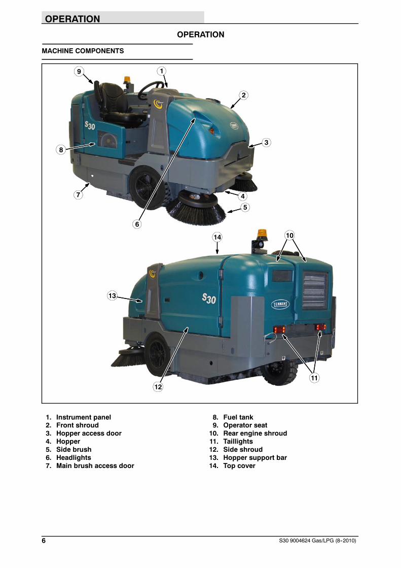
MACHINE COMPONENTS
9
2
3
7
1
4
13
14
12
5
6
8
11
10
1. Instrument panel2. Front shroud3. Hopper access door4. Hopper5. Side brush6. Headlights7. Main brush access door
8. Fuel tank9. Operator seat10. Rear engine shroud11. Taillights12. Side shroud13. Hopper support bar14. Top cover

OPERATION
7S30 9004624 Gas/LPG (2--2008)
CONTROLS AND INSTRUMENTS
2
1
7
9
18
11
15
14
812
17
19
20
16
543
6
10
13
(All models)1. Steering wheel2. Dash Fault Indicator lights3. Wand switch (option)4. Side brush light switch (option)5. Operating / hazard light switch6. Ignition switch7. Horn button8. Directional pedal9. Brake pedal10. Parking brake pedal
11. Steering column tilt pedal12. Main brush adjustment knob(S30 only)13. Side brush lever14. Side brush adjustment knob15. Main brush lever16. Hopper door switch17. Hopper raise / lower switch18. Engine speed switch19. Vacuum fan / filter shaker switch20. Indicator panel
TOUCH PANEL (S30 XP and X4)
8
6
10
2 3
4
5
7
9
11
12
13
1
1. Supervisor control buttons2. Hour meter / fuel indicator / fault code
indicator3. Contrast control button4. 1--STEP sweep button5. Engine speed button6. Vacuum fan button
7. Side brush button8. Hopper door open button9. Hopper door close button10. Hopper lower button11. Hopper raise button12. Filter shaker button13. Fault indicator light
OPERATION
8 S30 9004624 Gas/LPG (12--2008)
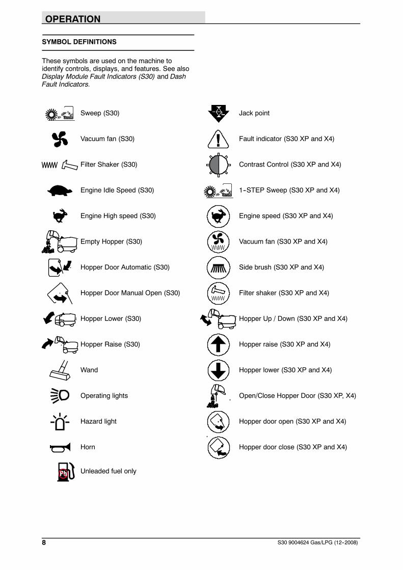
SYMBOL DEFINITIONS
These symbols are used on the machine toidentify controls, displays, and features. See alsoDisplay Module Fault Indicators (S30) and DashFault Indicators.
Sweep (S30) Jack point
Vacuum fan (S30) Fault indicator (S30 XP and X4)
Filter Shaker (S30) Contrast Control (S30 XP and X4)
Engine Idle Speed (S30) 1--STEP Sweep (S30 XP and X4)
Engine High speed (S30) Engine speed (S30 XP and X4)
Empty Hopper (S30) Vacuum fan (S30 XP and X4)
Hopper Door Automatic (S30) Side brush (S30 XP and X4)
Hopper Door Manual Open (S30) Filter shaker (S30 XP and X4)
Hopper Lower (S30) Hopper Up / Down (S30 XP and X4)
Hopper Raise (S30) Hopper raise (S30 XP and X4)
Wand Hopper lower (S30 XP and X4)
Operating lights Open/Close Hopper Door (S30 XP, X4)
Hazard light Hopper door open (S30 XP and X4)
Horn Hopper door close (S30 XP and X4)
Unleaded fuel only

OPERATION
9S30 9004624 Gas/LPG (2--2008)
OPERATION OF CONTROLS
DIRECTIONAL PEDAL
Press the top of the Directional pedal to moveforward and the bottom of the pedal to movebackward. The pedal returns to the neutralposition when it is released.
BRAKE PEDAL
Press the Brake pedal to stop the machine.
PARKING BRAKE PEDAL
Press the Brake pedal down as far as possibleand use toe to lock the Parking brake pedal intoplace. Press the Brake pedal to release theparking brake. The Parking brake pedal will returnto the unlocked position.
STEERING COLUMN TILT PEDAL
1. Step on the Steering column tilt pedal andadjust the steering column to the desiredposition.
2. Release the Steering column tilt pedal to lockin place.

OPERATION
10 S30 9004624 Gas/LPG (2--2008)
FUEL GAUGE
GASOLINE MACHINES
NOTE: Do not use leaded fuels. Leaded fuels willpermanently damage the system oxygen sensorand catalytic converter.
The Fuel indicator displays the amount of fuel leftin the tank. The fuel level fault indicator willilluminate when the fuel tank is near empty. Referto DISPLAY MODULE FAULT INDICATOR(S).
S30
S30 XP and X4
LPG MACHINES
For LPG machines, the Fuel indicator does NOTdisplay the amount of fuel in the LPG tank. It willdisplay all the indicator bars to show that somefuel is in the tank. The fuel level fault indicator willilluminate when the fuel level gets low. Refer toDISPLAY MODULE FAULT INDICATOR(S).
The LPG fuel gauge on the tank displays theamount of fuel in the LPG tank.

OPERATION
11S30 9004624 Gas/LPG (2--2008)
HOUR METER
The Hour meter records the hours the machinewas operated. Use this information to determinemachine service intervals.
S30
S30 XP and X4
SUPERVISOR CONTROL BUTTONS(S30 XP and X4)
The Supervisor Control buttons are for accessingthe configuration and diagnostic modes. Onlyproperly trained service personnel and TENNANTrepresentatives should access these modes.
ENGINE SPEED CONTROLS
Idle Speed: This speed is for starting the machine.
NOTE: S30 XP and X4 machines automaticallystart in idle speed.
S30 S30 XP and X4
Medium (Fast 1) Speed: This speed is for generalsweeping.
S30 S30 XP and X4
High (Fast 2) Speed: This speed is for sweepinglight litter or moving quickly between areas.
S30 S30 XP and X4
OPERATION
12 S30 9004624 Gas/LPG (2--2008)
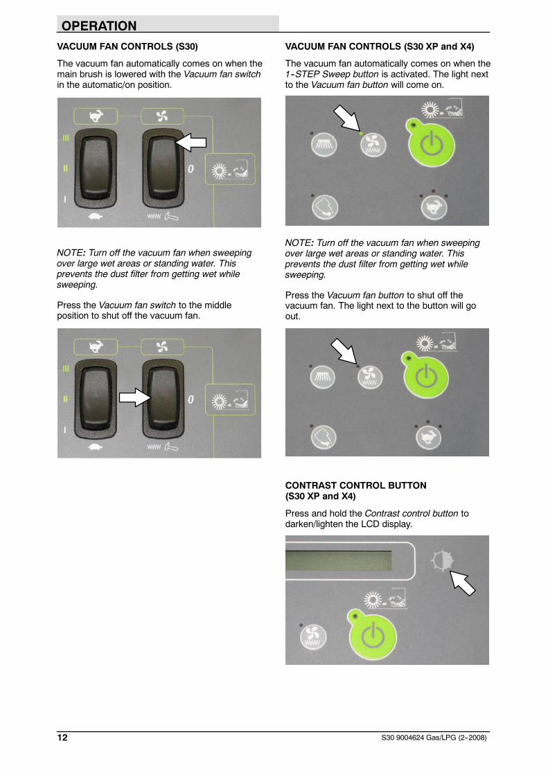
VACUUM FAN CONTROLS (S30)
The vacuum fan automatically comes on when themain brush is lowered with the Vacuum fan switchin the automatic/on position.
NOTE: Turn off the vacuum fan when sweepingover large wet areas or standing water. Thisprevents the dust filter from getting wet whilesweeping.
Press the Vacuum fan switch to the middleposition to shut off the vacuum fan.
VACUUM FAN CONTROLS (S30 XP and X4)
The vacuum fan automatically comes on when the1--STEP Sweep button is activated. The light nextto the Vacuum fan button will come on.
NOTE: Turn off the vacuum fan when sweepingover large wet areas or standing water. Thisprevents the dust filter from getting wet whilesweeping.
Press the Vacuum fan button to shut off thevacuum fan. The light next to the button will goout.
CONTRAST CONTROL BUTTON(S30 XP and X4)
Press and hold the Contrast control button todarken/lighten the LCD display.

OPERATION
13S30 9004624 Gas/LPG (2--2008)
FILTER SHAKER CONTROL (S30)
Press the Filter shaker switch. The filter shakerwill operate for 30 seconds.
FILTER SHAKER CONTROL (S30 XP and X4)
The filter shaker automatically activates for about30 seconds when the 1--STEP Sweep button isturned off.
Press the filter shaker switch to manually start the30 second shaker cycle or to stop the shakercycle.
OPERATING / HAZARD LIGHT SWITCH
Operating and Hazard Lights On: Press the top ofthe Operating / hazard light switch.
Operating Lights On: Press the Operating /hazard light switch to the middle position.
All Lights Off: Press the bottom of the Operating /hazard light switch.
SIDE BRUSH LIGHT SWITCH (OPTION)
Side Brush Lights On: Press the top of the Sidebrush light switch to turn the side brush light on.
Side Brush Lights Off: Press the bottom of theSide brush light switch to turn the side brush lightoff.

OPERATION
14 S30 9004624 Gas/LPG (2--2008)
OPERATOR SEAT
The front--to--back adjustment lever adjusts theseat position.
DELUXE SUSPENSION SEAT
The operator seat has three adjustments:backrest angle, operator weight, and front to back.
The backrest adjustment knob adjusts the angleof the backrest.
The weight adjustment knob controls the firmnessof the operator seat. Use the gauge next to theweight adjustment knob to help determine seatfirmness.
The front--to--back adjustment lever adjusts theseat position.
SEAT BELTS
FOR SAFETY: Before starting machine, adjustseat and fasten seat belt (if equipped).

OPERATION
15S30 9004624 Gas/LPG (12--2008)
BRUSH INFORMATION
For best results, use the correct brush type for thecleaning application.
NOTE: The amount and type of soilage play animportant role in determining the type of brushesto use. Contact a Tennant representative forspecific recommendations.
Polypropylene Sand Wedge Main Brush --Recommended for heavy accumulation of sandand other fine particles.
Polypropylene Window Main Brush --Recommended for light litter, especially onsmooth floors.
Polypropylene 8-double row Main Brush --Recommended for general sweeping applications.
Polypropylene and Wire 8-double row MainBrush -- Recommended for general sweeping andslightly impacted debris.
Nylon 8-double row Main Brush --Recommended for general sweeping, especiallyon rough or irregular surfaces. Nylon has a longwear life.
Nylon Full Fill Main Brush -- Recommended foraccumulation of sand and other fine particles.Nylon has a long wear life.
Nylon Patrol Main Brush -- Recommended forbulky debris swept at faster speeds.
Wire 8-double row Main Brush --Recommended for general sweeping and slightlyimpacted debris.
Natural Fiber and Full Fill Main Brush --Recommended for accumulation of sand andother very fine particles.
Polypropylene Side Brush -- Recommended forgeneral sweeping of light to medium debris.
Nylon Side Brush -- Recommended for generalsweeping of rough or irregular surfaces. Nylon hasa long wear life.
Flat Wire Side Brush -- Recommended foroutdoor curb-side sweeping where dirt is heavy orcompacted.
HOW THE MACHINE WORKS
The steering wheel controls the direction ofmachine travel. The directional pedal controls thespeed and forward/reverse direction. The brakepedal slows and stops the machine.
The side brush sweeps debris into the path of themain brush. The main brush sweeps debris fromthe floor into the hopper. The vacuum systempulls dust and air through the hopper and the dustcontrol system.
When sweeping is finished, shake the dust filterand empty the hopper.
PRE--OPERATION CHECKLIST
- Check the fuel level.
- Check the condition of the main brushes.Remove string, banding, plastic wrap, or otherdebris wrapped around the brushes.
- Check the main brush compartment rightskirts and seals for damage and wear.
- Right Side Brush: Check the condition of thebrush. Remove string, banding, plastic wrap,or other debris wrapped around the brush.
- Check the condition of the debris deflectionskirts.
- Check the hydraulic fluid level.
- Check the main brush compartment left skirtsand seals for damage and wear.
- Check the engine coolant level.
- Check the engine oil level.
- Check the radiator and hydraulic cooler finsfor debris.
- Check the headlights, taillights, and safetylights.
- Check the brakes and steering for properoperation.
- Check the service records to determinemaintenance requirements.
OPERATION
16 S30 9004624 Gas/LPG (6--2008)
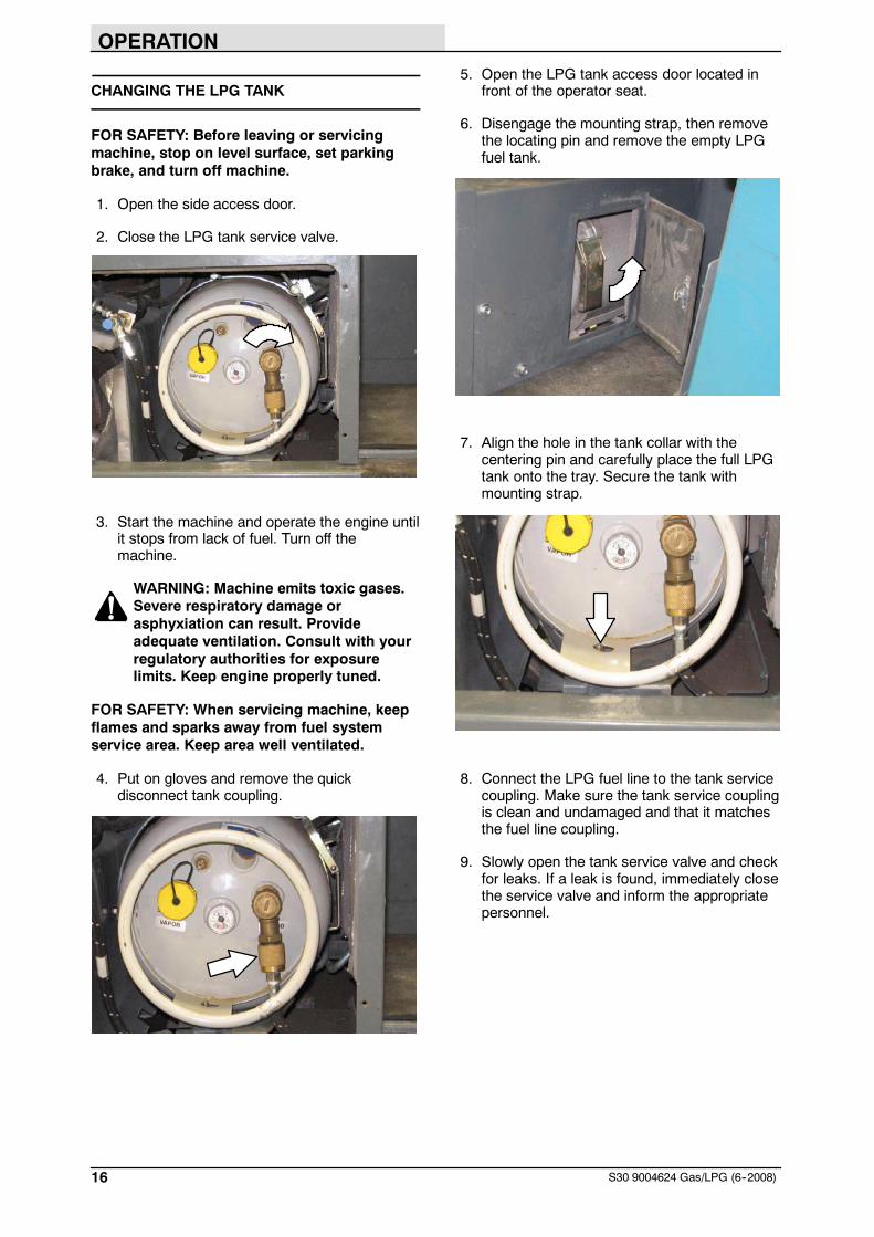
CHANGING THE LPG TANK
FOR SAFETY: Before leaving or servicingmachine, stop on level surface, set parkingbrake, and turn off machine.
1. Open the side access door.
2. Close the LPG tank service valve.
3. Start the machine and operate the engine untilit stops from lack of fuel. Turn off themachine.
WARNING: Machine emits toxic gases.Severe respiratory damage orasphyxiation can result. Provideadequate ventilation. Consult with yourregulatory authorities for exposurelimits. Keep engine properly tuned.
FOR SAFETY: When servicing machine, keepflames and sparks away from fuel systemservice area. Keep area well ventilated.
4. Put on gloves and remove the quickdisconnect tank coupling.
5. Open the LPG tank access door located infront of the operator seat.
6. Disengage the mounting strap, then removethe locating pin and remove the empty LPGfuel tank.
7. Align the hole in the tank collar with thecentering pin and carefully place the full LPGtank onto the tray. Secure the tank withmounting strap.
8. Connect the LPG fuel line to the tank servicecoupling. Make sure the tank service couplingis clean and undamaged and that it matchesthe fuel line coupling.
9. Slowly open the tank service valve and checkfor leaks. If a leak is found, immediately closethe service valve and inform the appropriatepersonnel.

OPERATION
17S30 9004624 Gas/LPG (2--2008)
STARTING THE MACHINE
1. LPG powered machines: Slowly open theliquid service valve.
NOTE: Opening the service valve too quickly maycause the service check valve to stop the flow ofLPG fuel. If the check valve stops the fuel flow,close the service valve, wait a few seconds, andslowly open the valve again.
2. Sit in the operator seat and press the brakepedal or set the parking brake.
FOR SAFETY: When starting machine, keepfoot on brake and directional pedal in neutral.
3. S30: Place the Engine speed switch into theidle position.
S30 XP and X4: The engine will automaticallystart in the idle speed.
4. Turn the ignition switch key until the enginestarts.
NOTE: Do not operate the starter motor for morethan 10 seconds at a time or after the engine hasstarted. Allow the starter to cool 15--20 secondsbetween starting attempts or damage to thestarter motor may occur.
5. Allow the engine and hydraulic system towarm up for three to five minutes.
WARNING: Machine emits toxic gases.Severe respiratory damage orasphyxiation can result. Provideadequate ventilation. Consult with yourregulatory authorities for exposurelimits. Keep engine properly tuned.
TURNING OFF THE MACHINE
1. Stop the machine and turn off all sweepingfunctions.
2. Turn the ignition switch key counter clockwiseto turn off the machine. Remain in theoperator seat until the engine is off.
CAUTION: LPG engine will run for a fewseconds after key is turned off. Applyparking brake before leaving machine.
NOTE: To protect engine emission componentson LPG powered machines, the engine willcontinue to operate for a few seconds after theignition switch is turned off.
FOR SAFETY: Before leaving or servicingmachine, stop on level surface, set parkingbrake, and turn off machine.

OPERATION
18 S30 9004624 Gas/LPG (2--2008)
WHILE OPERATING THE MACHINE
Pick up oversized debris before sweeping. Pick upwire, string, twine, large pieces of wood, or anyother debris that could become wrapped aroundor tangled in the brushes.
Drive as straight a path as possible. Avoidbumping into posts or scraping the sides of themachine. Overlap the sweep paths by severalcentimeters (a few inches).
Avoid turning the steering wheel too sharply whenthe machine is in motion. The machine is veryresponsive to the movement of the steering wheel.Avoid sudden turns, except in emergencies.
Adjust the machine speed and brush pressure.Use the lowest brush pressure for bestperformance.
Keep the machine moving to prevent damagingfloor finishes.
If poor cleaning performance is observed, stopcleaning and refer to MACHINETROUBLESHOOTING in this manual.
Perform the Daily Maintenance Procedures aftereach use (see MACHINE MAINTENANCE in thismanual).
Drive the machine slowly on inclines. Use thebrake pedal to control machine speed ondescending inclines. Sweep with the machine upinclines rather than down inclines.
FOR SAFETY: When using machine, go slowon inclines and slippery surfaces.
Maximum rated climb and descent for a fullhopper is 10_/18%. Maximum rated climb anddescent for an empty hopper is 14_/25%.
OPERATION
19S30 9004624 Gas/LPG (2--2008)
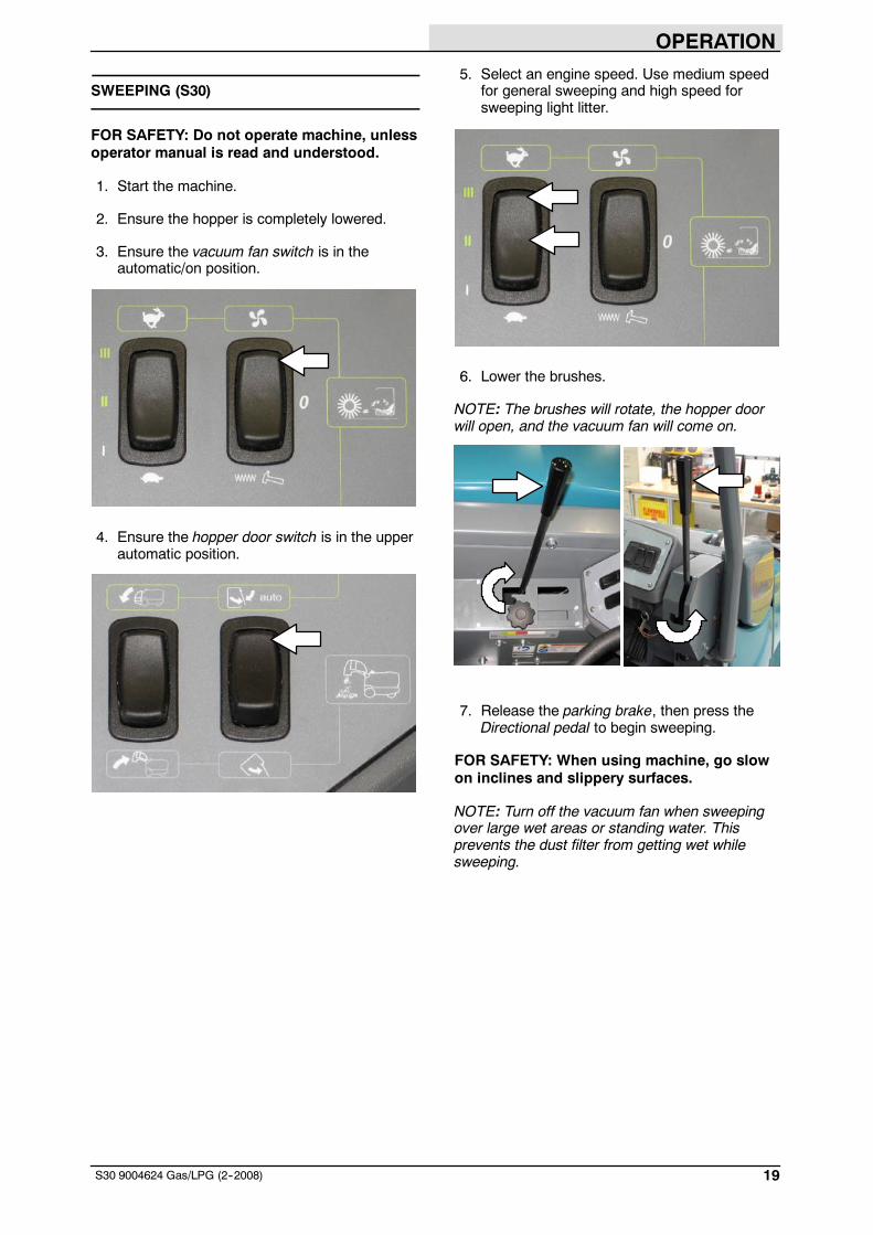
SWEEPING (S30)
FOR SAFETY: Do not operate machine, unlessoperator manual is read and understood.
1. Start the machine.
2. Ensure the hopper is completely lowered.
3. Ensure the vacuum fan switch is in theautomatic/on position.
4. Ensure the hopper door switch is in the upperautomatic position.
5. Select an engine speed. Use medium speedfor general sweeping and high speed forsweeping light litter.
6. Lower the brushes.
NOTE: The brushes will rotate, the hopper doorwill open, and the vacuum fan will come on.
7. Release the parking brake, then press theDirectional pedal to begin sweeping.
FOR SAFETY: When using machine, go slowon inclines and slippery surfaces.
NOTE: Turn off the vacuum fan when sweepingover large wet areas or standing water. Thisprevents the dust filter from getting wet whilesweeping.

OPERATION
20 S30 9004624 Gas/LPG (2--2008)
8. To stop sweeping, press the Brake pedal tostop the machine.
9. Raise the brushes.
10. Press the filter shaker switch to activate thehopper filter shaker. It will operate for about30 seconds.
11. Empty the debris hopper at the end of eachshift or as needed. See EMPTYING THEHOPPER section of this manual.
SWEEPING (S30 XP and X4)
FOR SAFETY: Do not operate machine, unlessoperator manual is read and understood.
1. Start the machine.
NOTE: Make sure the sweep modes / settings areset before sweeping.
2. Press the 1--STEP Sweep button. All thepreset sweeping functions will turn on. Thelight on the button will come on.
NOTE: The engine idle speed will increase, thebrushes will rotate, the hopper door will open, andthe vacuum fan will come on. Adjust the engineidle speed as needed.
3. Release the parking brake, then press theDirectional pedal to begin sweeping.
FOR SAFETY: When using machine, go slowon inclines and slippery surfaces.
NOTE: Turn off the vacuum fan when sweepingover large wet areas or standing water. Thisprevents the hopper dust filter from getting wetwhile sweeping.
4. To stop sweeping, press the Brake pedal tostop the machine.
5. Press the 1--STEP Sweep button. The light onthe button will turn off. All the preset sweepingfunctions will turn off and the automatic filtershaker will operate for about 30 seconds.
6. Empty the debris hopper at the end of eachshift or as needed. See EMPTYING THEHOPPER section of this manual.

OPERATION
21S30 9004624 Gas/LPG (2--2008)
EMPTYING THE HOPPER
1. Slowly drive the machine to the debris site ordebris container.
2. Stop the sweeping functions.
3. Press and hold the Hopper raise switch orbutton to raise the hopper.
S30 S30 XP and X4
FOR SAFETY: When using machine, makesure adequate clearance is available beforeraising hopper.
NOTE: Be aware the minimum ceiling heightneeded to raise the hopper is 2500 mm (98 in).
4. Slowly drive the machine up to the debriscontainer.
5. Lower the hopper into the debris container tocontrol dust.
NOTE: To prevent damaging the machine, DONOT hit the debris container with the machine.
6. Open the hopper door to empty the hopper.
S30 S30 XP and X4
7. S30: Place the Hopper door switch in theautomatic position to close the hopper door.
S30 XP and X4: Press the Hopper door closebutton to close the hopper door.
S30 S30 XP and X4
8. Raise the hopper enough to clear the top ofthe debris container.
9. Slowly back the machine away from thedebris site or debris container.
10. Press and hold the Hopper lower switch orbutton to completely lower the hopper.
S30 S30 XP and X4

OPERATION
22 S30 9004624 Gas/LPG (2--2008)
ENGAGING THE HOPPER SUPPORT BAR
The hopper support bar prevents the raisedhopper from falling. Always engage the hoppersupport bar whenever leaving the hopper in theraised position.
1. Set the parking brake.
2. Start the machine.
3. Completely raise the hopper.
S30 S30 XP and X4
WARNING: Lift arm pinch point. Stayclear of hopper lift arms.
FOR SAFETY: When using machine, makesure adequate clearance is available beforeraising hopper.
4. Rotate the support bar down into the hoppersupport clip.
WARNING: Raised hopper may fall.Engage hopper support bar.
5. Lower the hopper to lower the hopper supportbar onto the bracket.
6. Turn off the machine.
DISENGAGING THE HOPPER SUPPORT BAR
1. Start the machine.
2. Completely raise the hopper.
S30 S30 XP and X4
3. Set the parking brake.
4. Rotate the hopper support bar up into thestorage clip.
5. Completely lower the hopper.
WARNING: Lift arm pinch point. Stayclear of hopper lift arms.
OPERATION
23S30 9004624 Gas/LPG (02--2013)
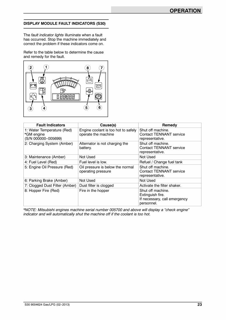
DISPLAY MODULE FAULT INDICATORS (S30)
The fault indicator lights illuminate when a faulthas occurred. Stop the machine immediately andcorrect the problem if these indicators come on.
Refer to the table below to determine the causeand remedy for the fault.
2
3
1
4 5
78
6
Fault Indicators Cause(s) Remedy1: Water Temperature (Red)*GM engine(S/N 000000--005699)
Engine coolant is too hot to safelyoperate the machine
Shut off machine.Contact TENNANT servicerepresentative.
2: Charging System (Amber) Alternator is not charging thebattery.
Shut off machine.Contact TENNANT servicerepresentative.
3: Maintenance (Amber) Not Used Not Used4: Fuel Level (Red) Fuel level is low. Refuel / Change fuel tank5: Engine Oil Pressure (Red) Oil pressure is below the normal
operating pressureShut off machine.Contact TENNANT servicerepresentative.
6: Parking Brake (Amber) Not Used Not Used7: Clogged Dust Filter (Amber) Dust filter is clogged Activate the filter shaker.8: Hopper Fire (Red) Fire in the hopper Shut off machine.
Extinguish fire.If necessary, call emergencypersonnel.
*NOTE: Mitsubishi engines machine serial number 005700 and above will display a “check engine”indicator and will automatically shut the machine off if the coolant is too hot.

OPERATION
24 S30 9004624 Gas/LPG (02--2013)
FAULT INDICATOR(S) (S30 XP and X4)
This machine is equipped with two visualindicators, a red indicator light and an LCD (liquidcrystal display).
The red indicator light will blink continuouslyindicating that a fault has occurred.
The LCD will display a fault code. If there is morethan one fault, each fault will alternately display.
All faults are also accompanied by an audiblealarm to alert the operator a fault has occurred.
Refer to the table below to determine the causeand remedy for the fault.
Fault Code(Displayed in LCD)
Cause(s) Result Remedy
F3: CLOGGED HYDFILTER
Hydraulic filter is clogged -- Shut off machine.Contact TENNANT servicerepresentative.
F4: SHAKER FILTER Hopper dust filter isclogged
-- Activate filter shaker tounclog hopper dust filter.
F5: HOPPER FIRE Fire in the hopper Terminates sweepingfunctions and closeshopper door
Shut off machine.Extinguish fire.If necessary, callemergency personnel.
F6: ALTERNATOR Alternator not charging -- Contact TENNANT servicerepresentative.
F7: LOW OIL PRESS Engine oil pressure is low Shuts down engine Contact TENNANT servicerepresentative.
F8: HIGH ENG TEMP*GM engine (S/N000000--005699)
Engine temperature is high Shuts down engine Shut off machine.Contact TENNANT servicerepresentative.
F9: HIGH HYD TEMP Hydraulic fluid temperatureis high
Cancels 1--Stepsweep functions
Shut off machine.Contact TENNANT servicerepresentative.
F10: LOW FUEL Low fuel -- Fill fuel tank (gasoline).Replace fuel tank (LPG).
F18: HOPPER UP Hopper is up Terminates sweepingfunctions
Lower hopper completely.
F20: UP KEY ERR Hopper up button failure Prevents all paneloperations
Shut off machine.Contact TENNANT servicerepresentative.
F21: DN KEY ERR Hopper down button failure Prevents all paneloperations
Shut off machine.Contact TENNANT servicerepresentative.
F22: OPN KEY ERR Hopper door open buttonfailure
Prevents all paneloperations
Shut off machine.Contact TENNANT servicerepresentative.
F23: CL KEY ERR Hopper door close buttonfailure
Prevents all paneloperations
Shut off machine.Contact TENNANT servicerepresentative.
F24: SEAT SWITCH(Option)
Operator not in the seatwhile engine is running andparking brake not engaged
Engine will shut off Engage parking brakebefore leaving the machine.
*NOTE: Mitsubishi engines machine serial number 005700 and above will display a “check engine”indicator and will automatically shut the machine off if the coolant is too hot.
OPERATION
25S30 9004624 Gas/LPG (02--2013)
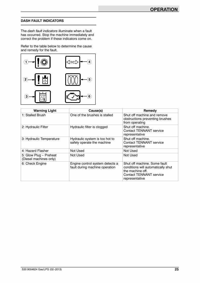
DASH FAULT INDICATORS
The dash fault indicators illuminate when a faulthas occurred. Stop the machine immediately andcorrect the problem if these indicators come on.
Refer to the table below to determine the causeand remedy for the fault.
1
2
3
4
5
6
Warning Light Cause(s) Remedy1: Stalled Brush One of the brushes is stalled Shut off machine and remove
obstructions preventing brushesfrom operating
2: Hydraulic Filter Hydraulic filter is clogged Shut off machine.Contact TENNANT servicerepresentative
3: Hydraulic Temperature Hydraulic system is too hot tosafely operate the machine
Shut off machine.Contact TENNANT servicerepresentative
4: Hazard Flasher Not Used Not Used5: Glow Plug -- Preheat(Diesel machines only)
Not Used Not Used
6: Check Engine Engine control system detects afault during machine operation
Shut off machine. Some faultconditions will automatically shutthe machine off.Contact TENNANT servicerepresentative

OPERATION
26 S30 9004624 Gas/LPG (3--2012)
OPTIONS
WAND (OPTION)
The vacuum wand allows the operator to pick-updebris that is out of reach of the machine’ssweeping path. The blower wand allows theoperator to blow debris out from areas that are outof reach of the machine’s sweeping path.
WARNING: Accident may occur. Do notoperate vacuum or blower wand whiledriving.
1. Raise the brushes.
2. Stop the machine and turn off the engine.
FOR SAFETY: Before leaving or servicingmachine, stop on level surface, set parkingbrake, and turn off machine.
3. Connect the hose assembly to the wand.
4. Attach the vacuum wand hose to the machineunder the vacuum wand door located on thefront of the hopper. Make sure the hopperdoor is closed when operating the vacuuumwand.
5. Attach the blower wand hose to the machineunder the blower wand door located on theleft side of the machine. Make sure thehopper door is open when operating theblower wand.
6. Start the machine.
WARNING: Machine emits toxic gases.Severe respiratory damage orasphyxiation can result. Provideadequate ventilation. Consult with yourregulatory authorities for exposurelimits. Keep engine properly tuned.
7. S30: Press theWand switch to start thevacuum fan. Then set the engine to highspeed.
S30 XP and X4: Press the Vacuum fan buttonto start the vacuum fan. The engine willautomatically set to the high speed.
S30 S30 XP and X4
8. Clean the area as needed.
9. S30: Press theWand switch to shut off thevacuum fan. Then set the engine to idlespeed.
S30 XP and X4: Press the Vacuum fan buttonto shut off the vacuum fan. Then set theengine to idle speed.
10. Shut the machine off.
11. Disconnect the wand from the machine andreturn it to the storage location.

OPERATION
27S30 9004624 Gas/LPG (2--2008)
HEATER / AIR CONDITIONER CONTROLS(OPTION)
Use the Heater / Air conditioner switch to turn onthe heater or air conditioner.
Top position: Air conditioner
Middle position: Off
Bottom position: Heater
Use the Temperature knob to control the cabheater temperature. Use the Fan knob to controlthe air conditioner temperature.
Use the Fan knob to control the fan speed. Thisknob affects the heater and air conditioner.
WINDSHIELD WIPER SWITCH (OPTION)
Use theWindshield wiper switch to turn on andadjust the windshield wiper speed.
Top position: High
Middle position: Low
Bottom position: Off
CAB LIGHT SWITCH (OPTION)
Press the Cab light switch to operate the cab light.

OPERATION
28 S30 9004624 Gas/LPG (2--2008)
TOWER BUMPERS (OPTION)
The tower bumpers help protect the rear enginecover from being damaged if the machine isbacked into an obstruction. Open the towerbumpers before opening rear engine shroud.
To open the bumpers:
1. Pull the pin from the bracket and the bumper.
2. Open the bumper.
3. Close and secure the tower bumpers beforeoperating the machine.
MACHINE TROUBLESHOOTING
Problem Cause Remedy
Excessive dusting Brush skirts and dust seals worn,damaged, out of adjustment
Replace or adjust brush skirts ordust seals
Dust filter clogged Shake and/or replace dust filter
Vacuum hose damaged Replace vacuum hose
Vacuum fan seal damaged Replace vacuum fan seal
Vacuum fan failure Call Tennant service representative
Poor sweeping performance Worn brush bristles Replace brushes
Brush pressure set too light Increase brush pressure
Main brush not properly adjusted Adjust brush
Debris caught in main brush drivemechanism
Remove debris from main brushdrive mechanism
Main and/or side brush drive failure Call Tennant service representative
Hopper is full Empty hopper
Hopper lip skirts worn or damaged Replace lip skirts
Improper brushes Refer to Brush Information or callTennant service representative
Engine speed set wrong Set engine speed correctly
Sweeping functions do notturn on
Hopper is up Completely lower hopper
Fire in the hopper Shut off machine. Extinguish fire.If necessary, call emergencypersonnel
S30 XP and X4: Hydraulic fluid toohot
Call Tennant service representative

MAINTENANCE
29S30 9004624 Gas/LPG (3--2012)
MAINTENANCE
2
3
4
1
5
6
7
8
9
5
MAINTENANCE CHART
Interval Key Description ProcedureLubricant/
Fluid
No. ofServicePoints
Daily 1 Engine Check oil level EO 1Check coolant level in reservoir WG 1Check air filter indicator -- 1
Daily 2 Hydraulic fluid reservoir Check fluid level HYDO 13 Dust filter Shake to clean -- 14 Main brush compartment
skirtsCheck for damage, wear, andadjustment
-- All
5 Hopper skirts Check for damage, wear, andadjustment
-- All
6 Main brush Check for damage and wear -- 17 Side brush Check for damage and wear -- 1
50 Hours 6 Main brush Rotate end-for-end and checkpattern
-- 1
100 Hours 8 Hydraulic cooler Clean core exterior -- 19 Rear tire Check pressure
790 + 35 kPa (115 + 5 psi)-- 1
-- Seals Check for damage or wear -- All
LUBRICANT/FLUID
EO Engine oil, 5W30 SAE--SG/SH only.. . . .HYDO TennantTrue premium hydraulic fluid or equivalent.WG Water and ethylene glycol anti-freeze, --34_ C (--30_ F). . .

MAINTENANCE
30 S30 9004624 Gas/LPG (3--2012)
ENGINE
ENGINE OIL
Check the engine oil level daily.
AIR FILTER INDICATOR
Check the indicator daily. The indicator red linewill move as the air filter element fills with dirt. Donot replace the air filter element until the red linereaches 5 kPa (20 in H2O) and the “SERVICEWHEN RED” window is filled with red. The enginemust be running to get an accurate air indicatorreading.
FOR SAFETY: When servicing machine, avoidmoving parts. Do not wear loose clothing orjewelry.
COOLING SYSTEM
FOR SAFETY: When servicing machine, avoidcontact with hot engine coolant.
Check the coolant level in the reservoir daily. Thecoolant level must be between the indicator markswhen the engine is cold.
FOR SAFETY: When servicing machine, donot remove cap from radiator when engine ishot. Allow engine to cool.
Check the radiator core exterior and hydrauliccooler fins for debris after every 100 hours ofoperation. Blow or rinse (with low pressure air orwater) all dust through the grille and radiator fins,in the opposite direction of normal air flow. Becareful to not bend the cooling fins when cleaning.Clean thoroughly to prevent the fins frombecoming encrusted with dust. To avoid crackingthe radiator, allow the radiator and cooler fins tocool before cleaning.
FOR SAFETY: When servicing machine, weareye and ear protection when usingpressurized air or water.

MAINTENANCE
31S30 9004624 Gas/LPG (2--2008)
HYDRAULICS
Check the hydraulic fluid level at operatingtemperature daily. The hopper must be downwhen checking hydraulic fluid level.
ATTENTION! Do not overfill the hydraulic fluidreservoir or operate the machine with a lowlevel of hydraulic fluid in the reservoir.Damage to the machine hydraulic system mayresult.
If using a locally-available hydraulic fluid, be surethe specifications match Tennant hydraulic fluidspecifications. Substitute fluids can causepremature failure of hydraulic components.
ATTENTION! Hydraulic components dependon system hydraulic fluid for internallubrication. Malfunctions, accelerated wear,and damage will result if dirt or othercontaminants enter the hydraulic system.
FUSES
Remove the relay panel cover to access fusesand relays. Always replace a fuse with a fuse ofthe same amperage. Extra 15 Amp fuses areprovided inside the relay panel drawer on therelay panel.
Refer to the diagram below for locations of thefuses on the relay panel.

MAINTENANCE
32 S30 9004624 Gas/LPG (6--2008)
Refer to the tables below for the fuses and circuitsprotected.
S30
Fuse Rating Circuit Protected
FU1 15 A Horn
FU2 15 A Key Switch, Engine,Instrumentation
FU3 15 A Turn Signals, 4--Way Flashers
FU4 15 A Extra Fused, Switched B+
FU5 15 A Main Brush Valves, Side BrushValves
FU6 15 A Hopper Valves
FU7 15 A Lights, Backup Alarm
FU8 15 A Extra Fused B+
FU9 15 A Shaker, Vacuum Fan Valve
FU10 15 A Not Used
FU11 60 A Main Power Fuse, In Line, In MainHarness
FU12 60 A Cab Power (Optional)
FU13 40 A Not Used
FU14 60 A Cab Power (Optional)
S30 XP and X4
Fuse Rating Circuit Protected
FU1 15 A Horn
FU2 15 A Key Switch, Engine,Instrumentation
FU3 15 A Turn Signals, 4--Way Flashers,Shaker
FU4 15 A Control Board
FU5 15 A Main Brush Valves, Side BrushValves
FU6 15 A Hopper Valves, Vacuum FanValves
FU7 15 A Lights, Backup Alarm
FU8 15 A Extra Fused B+
FU9 15 A Extra Switched, Fused B+
FU10 15 A Not Used
FU11 60 A Main Power Fuse, In Line, In MainHarness
FU12 60 A Cab Power (Optional)
FU13 40 A Not Used
FU14 60 A Cab Power (Optional)
NOTE: Always replace a fuse with a fuse of thesame amperage.
CAB FUSES (CAB OPTION)
The cab fuses are located in the fuse box insidethe cab. Remove the fuse cover to access thefuses.
Refer to the table below for the fuses and circuitscontrolled.
Fuse Rating Circuit Protected
FU1 5 A Lights
FU2 5 A Wiper
FU3 20 A Air Conditioner
FU4 2 A Heat
NOTE: Always replace a fuse with a fuse of thesame amperage.

MAINTENANCE
33S30 9004624 Gas/LPG (8--2010)
MAIN BRUSH
Check the brush daily for wear or damage.Remove any string or wire tangled on the mainbrush, main brush drive hub, or main brush idlerhub.
Replace the main brush when it no longer cleanseffectively.
REPLACING OR ROTATING THE MAIN BRUSH
1. Raise the brush head.
FOR SAFETY: Before leaving or servicingmachine, stop on level surface, set parkingbrake, and turn off machine.
2. Open the right side main brush access door.
3. Unlatch and remove the brush idler plate.
4. Pull the main brush from the main brushcompartment.
5. Replace or rotate the main brushend--for--end.
6. Slide the brush into the brush compartmentand all the way onto the drive plug.
7. Reinstall the brush idler plate.
8. Close the right side main brush access door.

MAINTENANCE
34 S30 9004624 Gas/LPG (2--2008)
ADJUSTING THE MAIN BRUSH WIDTH
FOR SAFETY: Before leaving or servicingmachine, stop on level surface, set parkingbrake, and turn off machine.
1. Compare the length of the main brush bristleswith the color band on the brush idler plate.
2. Loosen the main brush adjustment knob andslide the pointer so it matches the color bandon the brush idler plate. Retighten the knob.
3. Recheck the pattern. Readjust if necessary.

MAINTENANCE
35S30 9004624 Gas/LPG (8--2010)
SIDE BRUSH
Check the side brush daily for wear or damage.Remove any tangled string or wire from the sidebrush or side brush drive hub.
REPLACING THE SIDE BRUSH
Replace the brush(es) when it no longer cleanseffectively.
1. Raise the side brush.
FOR SAFETY: Before leaving or servicingmachine, stop on level surface, set parkingbrake, and turn off machine.
2. Remove the side brush retaining pin and thenremove the side brush.
NOTE: Remove the drive hub and put it on thenew brush if one is not installed.
3. Slide the new side brush onto the side brushdrive shaft and reinstall the retaining pin.
4. Adjust the side brush pattern. Refer toADJUSTING THE SIDE BRUSH PATTERN.
ADJUSTING THE SIDE BRUSH PATTERN
The side brush bristles should touch the floorbetween 10 o’clock and 4 o’clock when the brushis in motion.
350327
S30: Turn the side brush adjustment knobcounterclockwise to increase the brush patternand clockwise to decrease the brush pattern.
S30 XP and X4: Tighten the side brushadjustment knob into the side brush bracket toincrease the brush pattern and loosen the knob todecrease the brush pattern.

MAINTENANCE
36 S30 9004624 Gas/LPG (2--2008)
SKIRTS AND FLAPS
HOPPER SKIRTS
Check the hopper skirts for wear or damage daily.Replace the hopper skirts when they no longertouch the floor.
BRUSH DOOR SKIRTS
NOTE: Be sure the rear tire is properly inflatedbefore checking skirt clearances.
The brush door skirts should clear the floor by3 to 6 mm (0.12 to 0.25 in). Check the skirts forwear or damage and adjustment daily.
REAR SKIRT
NOTE: Be sure the rear tire is properly inflatedbefore checking skirt clearances.
The rear brush skirt should clear the floor by3 to 6 mm (0.12 to 0.25 in). Check the skirt forwear or damage and adjustment daily.
RECIRCULATION FLAP
The recirculation flap is self-adjusting. Check theflap for wear or damage daily.
MAINTENANCE
37S30 9004624 Gas/LPG (2--2008)
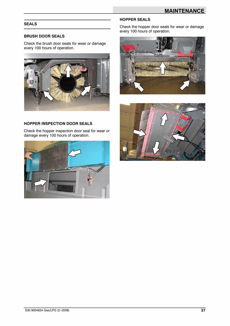
SEALS
BRUSH DOOR SEALS
Check the brush door seals for wear or damageevery 100 hours of operation.
HOPPER INSPECTION DOOR SEALS
Check the hopper inspection door seal for wear ordamage every 100 hours of operation.
HOPPER SEALS
Check the hopper door seals for wear or damageevery 100 hours of operation.

MAINTENANCE
38 S30 9004624 Gas/LPG (2--2008)
FILTER CHAMBER INLET SEAL
Check the filter chamber inlet seal for wear ordamage every 100 hours of operation.
DUST RETURN SEALS
Check the dust return seals for wear or damageevery 100 hours of operation.
VACUUM WAND DOOR SEALS (OPTION)
Check the vacuum wand door seal for wear ordamage every 100 hours of operation.
CYCLONIC PRE--FILTER SEALS
Check the cyclonic pre--filter seals for wear ordamage every 100 hours of operation.

MAINTENANCE
39S30 9004624 Gas/LPG (2--2008)
PUSHING, TOWING, AND TRANSPORTINGTHE MACHINE
PUSHING OR TOWING THE MACHINE
If the machine becomes disabled, it can bepushed from the front or rear, but only towed fromthe rear.
Use the bypass valve to prevent damaging thehydraulic system when pushing or towing themachine. This valve allows a disabled machine tobe moved for a very short distance and at a speedto not exceed 1.6 kp/h (1 mph). The machine isNOT intended to be pushed or towed a longdistance or at a high speed.
ATTENTION! Do not push or tow machine fora long distance or damage may occur to thepropelling system.
Turn the bypass valve located on the bottom ofthe propelling pump 90_ (either direction) from thenormal position before pushing or towing themachine. Return the bypass valve to the normalposition when finished pushing or towing themachine. Do Not use the bypass valve duringnormal machine operation.
TRANSPORTING THE MACHINE
FOR SAFETY: When loading/unloadingmachine onto/off truck or trailer, turn offmachine. Use truck or trailer that will supportthe weight of the machine. Set parking brakeafter machine is loaded. Block machine tires.Tie machine down to truck or trailer.
Route the tie--downs to the opposite ends of themachine and hook them to the brackets on thefloor of the trailer or truck. Tighten the tie--downstraps.
NOTE: It may be necessary to install tie-downbrackets to the floor of the trailer or truck.
MAINTENANCE
40 S30 9004624 Gas/LPG (2--2008)
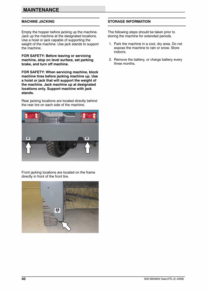
MACHINE JACKING
Empty the hopper before jacking up the machine.Jack up the machine at the designated locations.Use a hoist or jack capable of supporting theweight of the machine. Use jack stands to supportthe machine.
FOR SAFETY: Before leaving or servicingmachine, stop on level surface, set parkingbrake, and turn off machine.
FOR SAFETY: When servicing machine, blockmachine tires before jacking machine up. Usea hoist or jack that will support the weight ofthe machine. Jack machine up at designatedlocations only. Support machine with jackstands.
Rear jacking locations are located directly behindthe rear tire on each side of the machine.
Front jacking locations are located on the framedirectly in front of the front tire.
STORAGE INFORMATION
The following steps should be taken prior tostoring the machine for extended periods.
1. Park the machine in a cool, dry area. Do notexpose the machine to rain or snow. Storeindoors.
2. Remove the battery, or charge battery everythree months.

SPECIFICATIONS
41S30 9004624 Gas/LPG (3--2012)
SPECIFICATIONS
GENERAL MACHINE DIMENSIONS/CAPACITIES
Item Dimension/capacity
Length 2360 mm (93 in)
Height 1475 mm (58 in)
Height (with overhead guard) 2095 mm (82.5 in)
Width/frame 1590 mm (62.5 in)
Cleaning path width (Single side brush) 1590 mm (62.5 in)
Cleaning path width (Dual side brushes) 2030 mm (80 in)
Debris hopper volume capacity (Plastic and Steel) 395 L (14 ft3)
Debris hopper weight capacity (Plastic) 490 kg (1080 lbs)
Debris hopper weight capacity (Steel) 545 kg (1200 lbs)
Dump height (variable to) 1525 mm (60 in)
Minimum ceiling dump height 2500 mm (98 in)
Weight -- empty 1595 Kg (3520 lbs)
GVWR 2585 Kg (5700 lbs)
Transport ground clearance 100 mm (4 in)
Operating Sound Level At Operator Ear 80 1.5 dBA
Vibration level at steering wheel does not exceed 2.5 m/s@
Vibration level at operator seat does not exceed 0.5 m/s@
GENERAL MACHINE PERFORMANCE
Item Measure
Minimum aisle turn 2870 mm (113 in)
Travel speed forward (maximum) 13.0 Km/h (8 mph)
Maximum rated climb and descent (full hopper) 10_/18%
Maximum rated climb and descent (empty hopper) 14_/25%

SPECIFICATIONS
42 S30 9004624 Gas/LPG (8--2010)
MACHINE DIMENSIONS
2360 mm(93 in)
1590 mm(62.5 in)
2360 mm(93 in)
1590 mm(62.5 in)
2095 mm(82.5 in)
1475 mm(58 in)
2095 mm(82.5 in)
354726