gate, globe & check valves - forged steel
TRANSCRIPT

6
GATE, GLOBE & CHECK VALVES - FORGED STEEL
www.australianpipelinevalve.com.au
API 607-7th & ISO 10497Firesafe Certifi ed
ISO 15848-1 Class CO2Fugitive Emission Certifi ed
Click
SHORT VERSION
here for a complete version of this catalogue

6
QUALITY VALVE MANUFACTURER
QUALITY COMMITMENT
Quality is Our First Priority.
Consistent product quality and a proven
track record makes Australian Pipeline
Valve a dependable choice where total
reliability is the number one concern.
Since its founding, APV’s philosophy has
been focused on quality. Our valves
are manufactured in full compliance
to worldwide standards (such as
ASME/ANSI, API, EN, ISO, BS, AS).
70-78 Stanbel Road Salisbury Plain South Australia 5109 Telephone +61 (0)8 8285 0033 Fax +61 (0)8 8285 0044
email: [email protected]
www.australianpipelinevalve.com.au

6
Figure Number Abbreviations 4*
Standard Material Specification 5
Options / Accessories 6*
Special Seating / Disc Types & Special Ends 7
Screwed and Weld End Valves 8~20*
High Pressure Gate, Globe, Check Valves 21~25*
Bonnetless Globe Valves 26~27*
Bellow Sealed Valves 28~29
Flanged Gate, Globe & Check Valves 30~35
Parallel Slide Gate Valves 36~39*
Technical Considerations 40*
CONTENTS - SHORT VERSION*
© Copyright Australian Pipeline Valve 1990 - 2021 Edition
AUSTRAL IAN P I P E L I N E VA LVE 3
Catalogues, photos, brochures and technical publications are the exclusive property of Australian Pipeline Valve.Any unauthorised reproduction in total or in part, shall result in prosecution. Products and data sheets in this publication are subjectto change at anytime without notice. Australian Pipeline Valve reserves the right to carry out amendments to products and materials.
AUSTRALIAN PIPELINE VALVE
* This version excludes some of these pages, refer to full version at website.
www.australianpipelinevalve.com.au

6
* + Stellite hard faced optional
Bolted Bonnet (Spiral Wound Type)
Bolted Bonnet (Ring Type Joint)
Welded Bonnet (Full Penetration Welding)
Extended Bonnet (Full Penetration Welding)
AUSTRAL IAN P I P E L I N E VA LVE5
STANDARD MATERIAL SPECIFICATION
STANDARD MATERIAL SPECIFICATION
Material Part NameCarbon Steel
Low-Temp Carbon Steel
Alloy Steel
Stainless Steel
Special Alloys
Body Bonnet Cover
A105N A350/LF2 A182/F1
A182/F5
A182/F9
A182/F11
A182/F22
A182/F304
A182/304L
A182/F316
A182/F316L
A182/F317
A182/F317L
A182/F321
A182/F347
Monel
Inconel
Hastelloy
Stem Seat Ring *
A276/410 A276/304 A276/316
A276/410 A276/304 A276/316
A276/410 A276/304 A276/316
A276/304 A276/316 A276/321
A276/317 A276/347
Monel Inconel Hastelloy
Wedge / Disc * A276/410 A276/304 A276/316
A276/410 A276/304 A276/316
A276/410 A276/304 A276/316
A276/304 A276/316 A276/321
A276/317 A276/347
Monel Inconel Hastelloy
Yoke Sleeve Bush A582-416 A582-416 A582-416 A582-416 A582-416
Gland Flange A105N A105N A105N A182/F304 A182/F304
Gland Packing Graphite Graphite Graphite Graphite Graphite
Bonnet Bolt A193/B7 A320/L7 A193/B16 A193/B8M A193/B8M
Gland Bolt A193/B8 A193/B8 A193/B16 A193/B8M A193/B8M
Gland Nut A194/2H A194/2H A194/2H A194/8 A194/8
Gland A276/410 A276/410 A276/410 A276/304 A276/304
Handwheel Carbon Steel Carbon Steel Carbon Steel Carbon Steel Carbon Steel
GasketA204/304+GraphiteA240/316+Graphite
A204/304+GraphiteA240/316+Graphite
A204/304+GraphiteA240/316+Graphite
A204/304+GraphiteA240/316+Graphite
Special
Handwheel Nut Carbon Steel Carbon Steel Carbon Steel Carbon Steel Carbon Steel
Name Plate Aluminium Aluminium Aluminium A240/304 A240/304

AUSTRAL IAN P I P E L I N E VA LVE 7
Elastomeric Seat Insert(Piston Check Valves)
Elastomeric or Plastic Seat Insert(Globe Valves)
Disc Washer
Replaceable Disc Ring
Screw
Body Seat Overlay
Needle Point Metering Plug(Globe Valve)
Stem
Body
Disc
Elastomeric or Plastic Seat Insert(Gate Valves)
Seat Ring
WedgeReplaceable Insert
Flow Control Nozzle (Globe Valves)
Gasket
BodyDisc
Body Seat
Body Seat Overlay
Body
O-Ring
Spring
Integrally ReinforcedContoured End
Threaded
Integrally ReinforcedLip End
Socket Weld
Integrally ReinforcedContoured End
Threaded
Integrally ReinforcedLip End
Socket Weld
Integrally ReinforcedContoured End
Threaded
Integrally ReinforcedLip End
Socket Weld
Integrally ReinforcedContoured End
Threaded
Integrally ReinforcedLip End
Socket Weld
Male Threaded
Male Socket Weld Integrally ReinforcedLip End
Integrally Reinforced Contoured End
SPECIAL SEATING & ENDS
SPECIAL SEATING / DISC TYPES
SPECIAL ENDS
6 AUSTRAL IAN P I P E L I N E VA LVE8
17
16
15
14
13
12
11
10
9
8
7
6
5
4
3
2
1
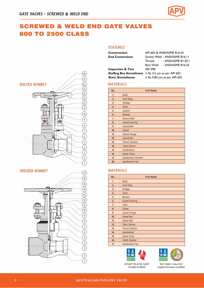
No. Part Name
1 Body
2 Seat Ring
3 Wedge
4 Stem
5 Gasket
6 Bonnet
7 Bonnet Bolt
8 Gland Packing
9 Gland Bolt
10 Gland
11 Gland Flange
12 Gland Nut
13 Thrust Washer
14 Yoke Sleeve
15 Handwheel
16 Name Plate
17 Handwheel Washer
18 Handwheel Nut
MATERIALS
WELDED BONNETNo. Part Name
1 Body
2 Seat Ring
3 Wedge
4 Stem
5 Bonnet
6 Gland Packing
7 Yoke
8 Gland
9 Gland Flange
10 Gland Nut
11 Gland Bolt
12 Yoke Sleeve
13 Thrust Washer
14 Handwheel
15 Name Plate
16 Tooth Washer
17 Handwheel Nut
MATERIALS
FEATURESConstruction API 602 & ANSI/ASME B16.34End Connections Socket Weld - ANSI/ASME B16.11 Thread - ANSI/ASME B1.20.1 Butt Weld - ANSI/ASME B16.25Inspection & Test API 598Stuffing Box Smoothness ≤Ra3.2µmasperAPI602Stem Smoothness ≤Ra0.80µmasperAPI602
GATE VALVES - SCREWED & WELD END
SCREWED & WELD END GATE VALVES800 TO 2500 CLASS
1
2
3
4
5
6
7
8
9
10
11
12
13
14
15
16
17
18
BOLTED BONNET
ISO 15848-1 Class C02Fugitive Emission Certified
API 607-7th & ISO 10497Firesafe Certified

AUSTRAL IAN P I P E L I N E VA LVE 9
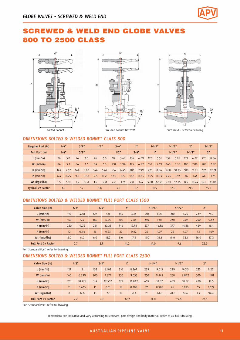
Regular Port (in) 1/4” 3/8” 1/2” 3/4” 1” 1-1/4” 1-1/2” 2” 2-1/2”
Full Port (in) 1/4” 3/8” 1/2” 3/4” 1” 1-1/4” 1-1/2” 2”
L (mm/in) 76 3.0 76 3.0 79 3.11 92 3.62 111 4.37 120 4.72 120 4.72 140 5.51 220 8.66
W (mm/in) 84 3.3 84 3.3 100 3.93 100 3.93 125 4.92 160 5.39 160 6.3 180 7.08 200 7.87
H (mm/in) 144 5.67 144 5.67 161 6.33 163 6.41 196 7.72 251 8.86 251 9.88 290 11.4 333 13.11
P (mm/in) 6.4 0.25 9.5 0.38 10.5 0.41 13.5 0.53 17 0.67 23.5 0.93 29 1.14 36 1.41 46.5 1.83
Wt (kgs/lbs) 1.5 3.31 1.5 3.31 1.5 3.31 2.2 4.9 2.8 6.4 5.60 12.35 5.60 12.35 8.5 18.74 13 28.66
Typical Cv Factor 2.0 4.6 5.6 12.0 23.5 48.0 78.0 105.0 200.0
DIMENSIONS BOLTED & WELDED BONNET CLASS 800
Full Port (in) 1/2” 3/4” 1” 1-1/4” 1-1/2” 2”
L (mm/in) 110 4.38 127 5.0 155 6.13 210 8.25 210 8.25 229 9.0
W (mm/in) 140 5.5 160 6.25 200 7.88 230 9.07 230 9.07 250 9.82
H (mm/in) 224 7.88 253 9.94 317 12.5 337 14.88 377 14.88 458 18.0
P (mm/in) 11 0.44 16 0.63 20 0.82 26 1.07 32 1.25 43 1.69
Wt (kgs/lbs) 5.0 11.0 7.0 15.4 10.0 22.0 18.2 40.1 18.0 39.7 30.0 66.1
Typical Cv Factor 10.6 24.5 38.0 56.0 80.0 197.0
DIMENSIONS BOLTED & WELDED BONNET FULL PORT CLASS 1500
Valve Size (in) 1/2” 3/4” 1” 1-1/4” 1-1/2” 2”
L (mm/in) 127 5 155 6.102 210 8.267 229 9.015 229 9.015 235 9.251
W (mm/in) 160 6.299 200 7.874 230 9.055 250 9.84 250 9.84 300 11.81
H (mm/in) 253 9.96 317 12.48 377 14.84 458 18.03 458 18.03 470 18.5
P (mm/in) 11 0.433 16 0.629 20 0.787 26 1.023 28.5 1.122 38.1 1.69
Wt (kgs/lbs) 8.0 17.6 11.0 24.2 19.0 41.8 34.0 74.8 32.0 70.4 45.0 99.0
Typical Cv Factor 5.6 10.6 24.5 59.8 68.0 95.0
DIMENSIONS BOLTED & WELDED BONNET FULL PORT CLASS 2500
For ‘Standard Port” refer to drawing.
For ‘Standard Port” refer to drawing.
Dimensions are indicative and vary according to standard, port design and body material. Refer to as-built drawing.
H
L
øP
W
H
øP
W
L
W
H
øP
L1
Extended End - Refer to DrawingWelded BonnetBolted Bonnet
L2
øP
W
Butt Weld - Refer to Drawing
H
GATE VALVES - SCREWED & WELD END
SCREWED & WELD END GATE VALVES800 TO 2500 CLASS

6 AUSTRAL IAN P I P E L I N E VA LVE10
17
16
15
14
13
12
11
10
9
8
7
6
5
4
3
2
1ISO 15848-1 Class CO2
Fugitive Emission Certified
No. Part Name
1 Body
2 Seat Ring
3 Wedge
4 Stem
5 Gasket
6 Bonnet
7 Bonnet Bolt
8 Gland Packing
9 Gland Bolt
10 Gland
11 Gland Flange
12 Gland Nut
13 Thrust Washer
14 Yoke Sleeve
15 Handwheel
16 Name Plate
17 Handwheel Washer
18 Handwheel Nut
MATERIALS
WELDED BONNETNo. Part Name
1 Body
2 Seat Ring
3 Wedge
4 Stem
5 Bonnet
6 Gland Packing
7 Yoke
8 Gland
9 Gland Flange
10 Gland Nut
11 Gland Bolt
12 Yoke Sleeve
13 Thrust Washer
14 Handwheel
15 Name Plate
16 Tooth Washer
17 Handwheel Nut
MATERIALS
FEATURESConstruction API 602 & ANSI/ASME B16.34End Connections Socket Weld - ANSI/ASME B16.11 Thread - ANSI/ASME B1.20.1 Butt Weld - ANSI/ASME B16.25Inspection & Test API 598Stuffing Box Smoothness ≤Ra3.2µmasperAPI602Stem Smoothness ≤Ra0.80µmasperAPI602
GATE VALVES - SCREWED & WELD END
SCREWED & WELD END GATE VALVES800 TO 2500 CLASS
1
2
3
4
5
6
7
8
9
10
11
12
13
14
15
16
17
18
BOLTED BONNET
AUSTRAL IAN P I P E L I N E VA LVE 11
Dimensions are indicative and vary according to standard, port design and body material. Refer to as-built drawing.
Regular Port (in) 1/4” 3/8” 1/2” 3/4” 1” 1-1/4” 1-1/2” 2” 2-1/2”
Full Port (in) 1/4” 3/8” 1/2” 3/4” 1” 1-1/4” 1-1/2” 2”
L (mm/in) 76 3.0 76 3.0 76 3.0 92 3.62 104 4.09 120 5.51 152 5.98 172 6.77 220 8.66
W (mm/in) 84 3.3 84 3.3 84 3.3 100 3.94 125 4.92 137 5.39 160 6.30 180 7.08 200 7.87
H (mm/in) 144 5.67 144 5.67 144 5.67 164 6.45 203 7.99 225 8.86 260 10.23 300 11.81 323 12.71
P (mm/in) 6.4 0.25 9.5 0.38 9.5 0.38 12.5 0.5 18.5 0.73 23.5 0.93 23.5 0.93 36 1.41 44 1.73
Wt (kgs/lbs) 1.5 3.31 1.5 3.31 1.5 3.31 2.2 4.9 2.8 6.4 5.60 12.35 5.60 12.35 8.5 18.74 15.0 33.06
Typical Cv Factor 1.0 1.7 1.8 3.6 6.5 11.5 17.0 21.0 35.0
Valve Size (in) 1/2” 3/4” 1” 1-1/4” 1-1/2” 2”
L (mm/in) 110 4.38 127 5.0 155 6.13 210 8.25 210 8.25 229 9.0
W (mm/in) 140 5.5 160 6.25 200 7.88 230 9.07 230 9.07 250 9.82
H (mm/in) 230 9.03 261 10.25 314 12.38 377 14.88 377 14.88 459 18.1
P (mm/in) 12 0.44 16 0.63 20 0.82 26 1.07 26 1.07 43 1.69
Wt (kgs/lbs) 5.0 11.0 6.0 13.2 8.0 17.6 15.0 33.1 15.0 33.1 26.0 57.3
Full Port Cv Factor 2.7 5.9 11.2 14.0 19.6 23.3
Valve Size (in) 1/2” 3/4” 1” 1-1/4” 1-1/2” 2”
L (mm/in) 127 5 155 6.102 210 8.267 229 9.015 229 9.015 235 9.251
W (mm/in) 160 6.299 200 7.874 230 9.055 250 9.842 250 9.842 300 11.81
H (mm/in) 261 10.275 314 12.362 377 14.842 459 18.07 459 18.07 470 18.5
P (mm/in) 11 0.433 13 0.51 18 0.708 23 0.905 26 1.023 35 1.377
Wt (kgs/lbs) 8 17.6 10 22 17 37.4 28 61.6 28.0 61.6 43 94.6
Full Port Cv Factor 2.7 5.9 12.2 14.0 19.6 23.3
DIMENSIONS BOLTED & WELDED BONNET CLASS 800
DIMENSIONS BOLTED & WELDED BONNET FULL PORT CLASS 1500
DIMENSIONS BOLTED & WELDED BONNET FULL PORT CLASS 2500For ‘Standard Port’ refer to drawing.
For ‘Standard Port’ refer to drawing.
øP
H
L
W W
H
L2
Welded Bonnet NPT/SW Butt Weld - Refer to Drawing
øP
H
L
øP
W
Bolted Bonnet
GLOBE VALVES - SCREWED & WELD END
SCREWED & WELD END GLOBE VALVES800 TO 2500 CLASS

6 AUSTRAL IAN P I P E L I N E VA LVE12
BOLTED BONNET
WELDED BONNET
No. Part Name
1 Body
2 Disc
3 Stem
4 Gasket
5 Bonnet
6 Bonnet Bolt
7 Gland Packing
8 Gland Bolt
9 Gland
10 Gland Flange
11 Gland Nut
12 Yoke Bush
13 Handwheel
14 Name Plate
15 Handwheel Washer
16 Handwheel Nut
No. Part Name
1 Body
2 Seat
3 Pad
4 Disc
5 Stem
6 Disc Nut
7 Bonnet
8 Gland Packing
9 Yoke
10 Gland
11 Gland Flange
12 Gland Nut
13 Gland Bolt
14 Yoke Bush
15 Handwheel
16 Name Plate
17 Tooth Washer
18 Handwheel Nut
MATERIALS
MATERIALS
1
2
3
4
5
6
7
8
9
10
11
12
13
14
15
16
GLOBE VALVES - SCREWED & WELD END
SCREWED & WELD END Y-TYPE GLOBE VALVES800 TO 2500 CLASS
1
2
3
4
5
6
7
8
9
10
11
12
13
14
15
16
17
18
FEATURESConstruction API 602, BS 5352 &
ASME B16.34 (ISO 15761)End Connections Socket Weld - ANSI/ASME B16.11 Thread - ANSI/ASME B1.20.1 Butt Weld - ANSI/ASME B16.25Inspection & Test API 598 / BS 5146Stuffing Box Smoothness ≤Ra3.2µmasperAPI602Stem Smoothness ≤Ra0.80µmasperAPI602

AUSTRAL IAN P I P E L I N E VA LVE 13
Dimensions are indicative and vary according to standard, port design and body material. Refer to as-built drawing.
Regular Port Size (in) 1/4” 3/8” 1/2” 3/4” 1” 1-1/4” 1-1/2” 2” 2-1/2”
Full Port Size (in) 1/4” 3/8” 1/2” 3/4” 1” 1-1/4” 1-1/2” 2”
L (mm/in) 76 3.0 76 3.0 76 3.0 92 3.55 102 4.02 124 4.89 124 4.89 152 5.99 200 7.87
W (mm/in) 84 3.3 84 3.3 84 3.3 97 3.82 97 3.82 137 5.39 137 5.39 157 6.18 200 7.87
H (mm/in) 167 6.58 167 6.58 167 6.58 180 7.09 207 8.15 225 10.04 225 10.04 300 11.82 352 13.85
P (mm/in) 6.4 0.25 9.5 0.38 9.5 0.38 12.5 0.5 18.5 0.73 23.5 0.93 30.5 1.20 36.0 1.41 45.0 1.77
Wt (kgs/lbs) 1.6 3.53 1.6 3.53 1.6 3.53 1.9 4.2 3.2 7.1 6.4 14.1 6.4 14.1 9.3 20.5 16.0 35.27
Typical Cv Factor 2.9 3.9 4.5 5.5 10.0 18.0 29.5 40.0 52.0
DIMENSIONS WELDED BONNET CLASS 800
Regular Port Size (in) 1/4” 3/8” 1/2” 3/4” 1” 1-1/4” 1-1/2” 2” 2-1/2”
Full Port Size (in) 1/4” 3/8” 1/2” 3/4” 1” 1-1/4” 1-1/2” 2”
L (mm/in) 76 3.0 76 3.0 76 3.0 92 3.62 104 4.02 124 4.89 124 4.89 152 5.99 200 7.87
W (mm/in) 84 3.3 84 3.3 84 3.3 97 3.82 97 3.82 137 5.39 137 5.39 157 6.18 200 7.87
H (mm/in) 167 6.58 167 6.58 167 6.58 180 7.09 207 8.15 225 10.04 225 10.04 300 11.82 352 13.85
P (mm/in) 6.4 0.25 9.5 0.38 9.5 0.38 12.5 0.5 18.5 0.73 23.5 0.93 30.5 1.20 36.0 1.41 45.0 1.77
Wt (kgs/lbs) 1.8 3.97 1.8 3.97 1.8 3.97 2.1 4.83 3.5 7.72 6.70 14.8 6.70 14.8 9.7 21.4 16.0 35.27
Typical Cv Factor 2.9 3.9 4.5 5.5 10.0 18.0 29.5 40.0 52.0
DIMENSIONS BOLTED BONNET CLASS 800
80NB ~ 100NB (3” - 4”) refer to drawing
80NB ~ 100NB (3” - 4”) refer to drawing
H
L
øP
W
L
øP
W
H H
L2
W
Flanged Ends - Refer to Drawing
øP
Welded BonnetBolted Bonnet
GLOBE VALVES - SCREWED & WELD END
SCREWED & WELD END Y-TYPE GLOBE VALVESOUTSIDE SCREW & YOKE/SW, NPT, BW, CLASS 800
6 AUSTRAL IAN P I P E L I N E VA LVE14
Dimensions are indicative and vary according to standard, port design and body material. Refer to as-built drawing.
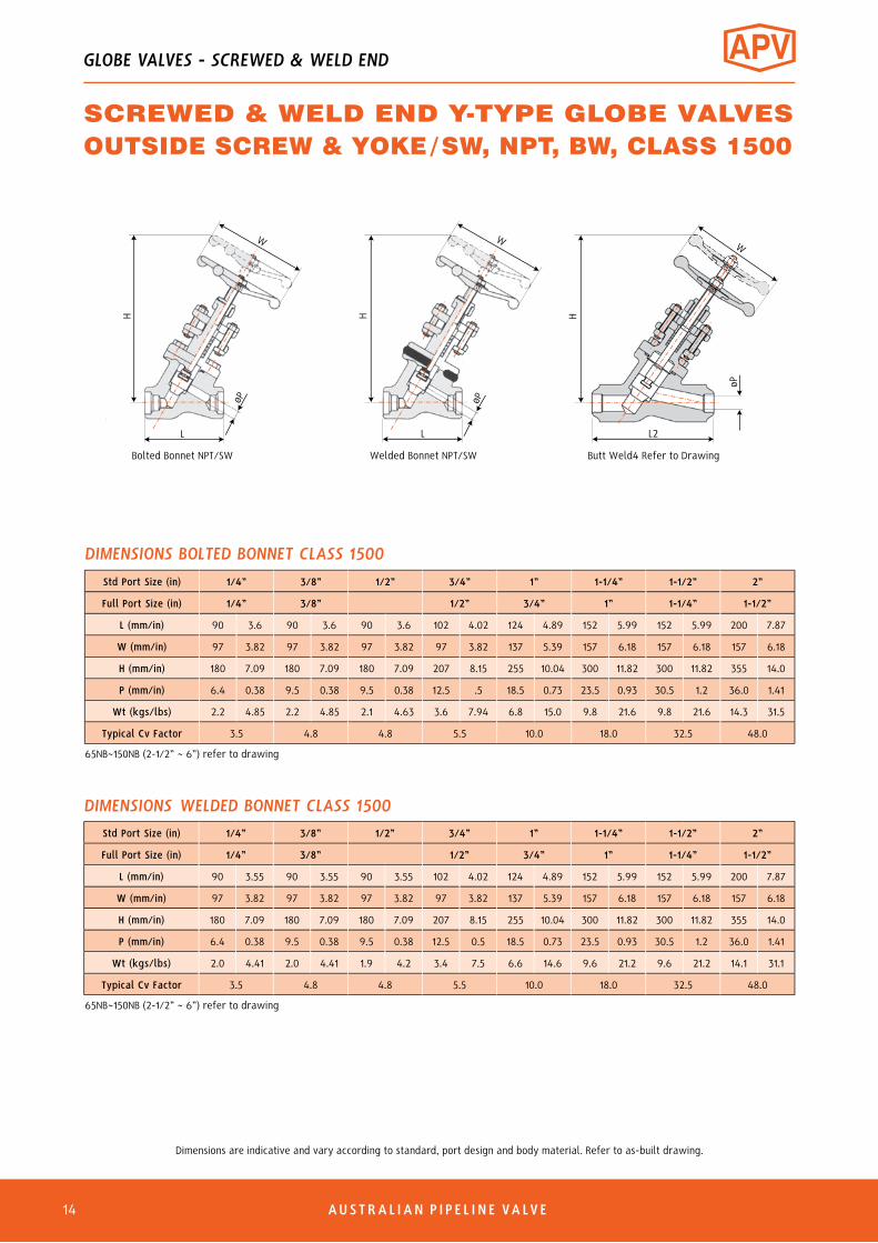
Std Port Size (in) 1/4” 3/8” 1/2” 3/4” 1” 1-1/4” 1-1/2” 2”
Full Port Size (in) 1/4” 3/8” 1/2” 3/4” 1” 1-1/4” 1-1/2”
L (mm/in) 90 3.6 90 3.6 90 3.6 102 4.02 124 4.89 152 5.99 152 5.99 200 7.87
W (mm/in) 97 3.82 97 3.82 97 3.82 97 3.82 137 5.39 157 6.18 157 6.18 157 6.18
H (mm/in) 180 7.09 180 7.09 180 7.09 207 8.15 255 10.04 300 11.82 300 11.82 355 14.0
P (mm/in) 6.4 0.38 9.5 0.38 9.5 0.38 12.5 .5 18.5 0.73 23.5 0.93 30.5 1.2 36.0 1.41
Wt (kgs/lbs) 2.2 4.85 2.2 4.85 2.1 4.63 3.6 7.94 6.8 15.0 9.8 21.6 9.8 21.6 14.3 31.5
Typical Cv Factor 3.5 4.8 4.8 5.5 10.0 18.0 32.5 48.0
DIMENSIONS BOLTED BONNET CLASS 1500
Std Port Size (in) 1/4” 3/8” 1/2” 3/4” 1” 1-1/4” 1-1/2” 2”
Full Port Size (in) 1/4” 3/8” 1/2” 3/4” 1” 1-1/4” 1-1/2”
L (mm/in) 90 3.55 90 3.55 90 3.55 102 4.02 124 4.89 152 5.99 152 5.99 200 7.87
W (mm/in) 97 3.82 97 3.82 97 3.82 97 3.82 137 5.39 157 6.18 157 6.18 157 6.18
H (mm/in) 180 7.09 180 7.09 180 7.09 207 8.15 255 10.04 300 11.82 300 11.82 355 14.0
P (mm/in) 6.4 0.38 9.5 0.38 9.5 0.38 12.5 0.5 18.5 0.73 23.5 0.93 30.5 1.2 36.0 1.41
Wt (kgs/lbs) 2.0 4.41 2.0 4.41 1.9 4.2 3.4 7.5 6.6 14.6 9.6 21.2 9.6 21.2 14.1 31.1
Typical Cv Factor 3.5 4.8 4.8 5.5 10.0 18.0 32.5 48.0
DIMENSIONS WELDED BONNET CLASS 1500
65NB~150NB (2-1/2” ~ 6”) refer to drawing
65NB~150NB (2-1/2” ~ 6”) refer to drawing
H
L
W
øP
WøP
H
L L2
H
W
øP
Butt Weld4 Refer to DrawingWelded Bonnet NPT/SWBolted Bonnet NPT/SW
GLOBE VALVES - SCREWED & WELD END
SCREWED & WELD END Y-TYPE GLOBE VALVESOUTSIDE SCREW & YOKE/SW, NPT, BW, CLASS 1500
AUSTRAL IAN P I P E L I N E VA LVE 16
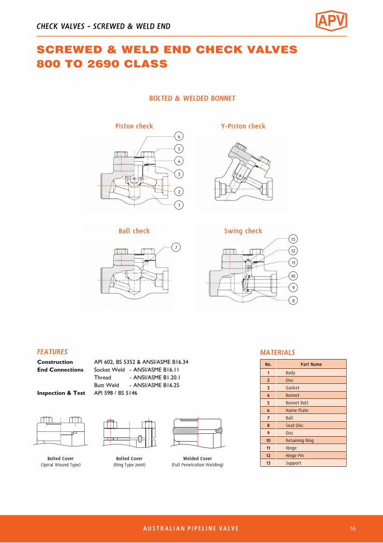
FEATURESConstruction API 602, BS 5352 & ANSI/ASME B16.34End Connections Socket Weld - ANSI/ASME B16.11 Thread - ANSI/ASME B1.20.1 Butt Weld - ANSI/ASME B16.25Inspection & Test API 598 / BS 5146
No. Part Name
1 Body
2 Disc
3 Gasket
4 Bonnet
5 Bonnet Bolt
6 Name Plate
7 Ball
8 Seat Disc
9 Disc
10 Retaining Ring
11 Hinge
12 Hinge Pin
13 SupportBolted Cover
(Spiral Wound Type)Bolted Cover
(Ring Type Joint)Welded Cover
(Full Penetration Welding)
MATERIALS
CHECK VALVES - SCREWED & WELD END
SCREWED & WELD END CHECK VALVES800 TO 2690 CLASS
BOLTED & WELDED BONNET
Piston check6
5
4
3
2
1
Y-Piston check
7
Ball check13
12
11
10
9
8
Swing check

6
DIMENSIONAL DRAWINGS
Swing check bolted bonnet Y-type piston check bolted bonnet
H
H
L
øP
L
øP
Piston check bolted bonnet Ball check bolted bonnet
H
L
øP
H
L
øP
øP
L2
H1
ASME B16.25 - Refer to drawing for dimensions
Butt Weld
Piston check welded bonnet
H
L
øP
L
øP
H
Piston check Y-type welded bonnet
AUSTRAL IAN P I P E L I N E VA LVE17
CHECK VALVES - SCREWED & WELD END
SCREWED & WELD END CHECK VALVES800 TO 2690 CLASS

Regular Port (in) 1/4” 3/8” 1/2” 3/4” 1” 1-1/4” 1-1/2” 2” 2-1/2”
Full Port (in) 1/4” 3/8” 1/2” 3/4” 1” 1-1/4” 1-1/2” 2”
L (mm/in) 76 3.0 76 3.0 79 3.11 92 3.62 111 4.37 140 5.5 152 5.98 172 6.77 220 8.66
H (mm/in) 46 1.8 46 1.8 46 1.8 61 2.40 78 3.07 75 2.95 84 3.30 118 4.64 140 5.51
P (mm/in) 6.4 0.25 9.5 0.38 9.5 0.38 12.5 0.5 17.5 0.69 23.5 0.93 30 1.18 35 1.37
Wt (kgs/lbs) 1 2.2 1 2.2 1 2.2 1.5 3.3 2 4.4 4.1 9 4.1 9 6.4 14.2 10.0 0.39
Typical Cv Factor 0.7 1.0 1.2 3.4 6.2 12.9 15.9 18.9 27.0
DIMENSIONS PISTON CHECK / BALL CHECK
Regular Port (in) 1/4” 3/8” 1/2” 3/4” 1” 1-1/4” 1-1/2” 2” 2-1/2”
Full Port (in) 1/4” 3/8” 1/2” 3/4” 1” 1-1/4” 1-1/2” 2”
L (mm/in) 76 3.0 76 3.0 79 3.11 92 3.62 111 4.37 115 4.53 120 4.72 140 5.51 220 8.66
H (mm/in) 46 1.8 46 1.8 46 1.8 61 2.40 78 3.07 75 2.95 84 3.30 120 4.72 140 5.51
P (mm/in) 6.4 0.25 9.5 0.38 10.0 0.39 13.5 0.53 18 0.71 23.5 0.93 30 1.18 36.0 1.41
Wt (kgs/lbs) 1.0 2.2 1.0 2.2 1.0 2.2 1.5 3.3 2.0 4.4 4.1 9.0 4.1 9.0 6.0 14.2 10.0 0.39
Typical Cv Factor 2.6 3.8 4.0 6.3 13.5 18.3 28.3 53.4 70.0
DIMENSIONS SWING CHECK
Regular Port (in) 1/4” 3/8” 1/2” 3/4” 1” 1-1/4” 1-1/2” 2”
Full Port (in) 1/4” 3/8” 1/2” 3/4” 1” 1-1/4” 1-1/2”
L (mm/in) 76 3.0 76 3.0 76 3.0 90 3.55 102 4.02 124 4.89 124 4.89 152 5.99
H (mm/in) 67 2.8 67 2.6 67 2.6 77 3.0 80 3.15 111 4.4 111 4.4 138 5.4
P (mm/in) 6.4 0.25 9.5 0.38 9.5 0.38 12.5 0.5 18.5 0.73 23.5 0.93 30.5 1.2 36.0 1.41
Wt (kgs/lbs) 1.2 2.6 1.2 2.6 1.2 2.6 1.4 3.1 2.4 5.3 5.2 11.5 5.2 11.5 7 15.4
Typical Cv Factor 2.8 3.9 3.9 4.8 8.2 13.0 27.0 39.0
DIMENSIONS Y-PISTON
Dimensions are indicative and vary according to standard, port design and body material. Refer to as-built drawing.
80NB~150NB (2-1/2” ~ 6”) refer to drawing
80NB~150NB (2-1/2” ~ 6”) refer to drawing
80NB~150NB (2-1/2” ~ 6”) refer to drawing
AUSTRAL IAN P I P E L I N E VA LVE 18
CHECK VALVES - SCREWED & WELD END
SCREWED & WELD END CHECK VALVESREGULAR & FULL PORT CLASS 800

6
Std Port (in) 1/4” 3/8” 1/2” 3/4” 1” 1-1/4” 1-1/2” 2”
L (mm/in) 92 3.62 92 3.62 92 3.62 111 4.37 120 4.72 146 5.74 172 6.77 200 7.87
H (mm/in) 56 2.2 56 2.2 56 2.2 78 3.07 84 3.30 100 3.94 118 4.64 138 5.43
P (mm/in) 6.4 0.25 9.5 0.38 10 0.39 12.5 0.5 18.5 0.73 23.5 0.93 30.5 1.20 36.0 1.41
Wt (kgs/lbs) 1.5 3.3 1.5 3.3 1.5 3.3 2.0 4.4 4.1 9 6.4 14.2 6.4 14.2 9.8 21.6
Typical Cv Factor 0.7 1.0 1.2 3.4 6.2 13.9 14.9 18.2
DIMENSIONS PISTON CHECK / BALL CHECK
Std Port (in) 1/4” 3/8” 1/2” 3/4” 1” 1-1/4” 1-1/2” 2”
L (mm/in) 92 3.62 92 3.62 92 3.62 111 4.37 120 4.72 146 5.74 140 5.51 178 7.0
H (mm/in) 56 2.2 56 2.2 56 2.2 78 3.07 84 3.30 100 3.94 120 4.72 133 5.23
P (mm/in) 6.4 0.25 9.5 0.38 10 0.39 13 0.51 17.5 0.69 23.5 0.93 30 1.18 36.0 1.41
Wt (kgs/lbs) 1.5 3.3 1.5 3.3 1.5 3.3 2.0 4.4 4.1 9.0 6.4 14.2 6.4 14.2 9.8 21.6
Typical Cv Factor 2.6 4.0 4.0 6.3 13.5 18.3 28.3 53.4
DIMENSIONS SWING CHECK
Std Port (in) 1/4” 3/8” 1/2” 3/4” 1” 1-1/4” 1-1/2” 2”
L (mm/in) 90 3.55 90 3.55 90 3.55 102 4.02 124 4.89 152 5.99 152 5.99 200 7.87
H (mm/in) 77 3.0 77 3.0 77 3.0 80 3.15 111 4.4 138 5.4 138 5.4 178 7.0
P (mm/in) 6.4 0.25 9.5 0.38 9.5 0.38 12.5 0.5 18.5 0.3 23.5 0.93 30.5 1.20 36.0 1.41
Wt (kgs/lbs) 1.4 3.1 1.4 3.1 1.4 3.1 2.4 5.3 5.2 11.5 7.0 15.4 7.1 15.4 10.3 22.7
Typical Cv Factor 3.5 3.8 5.0 12.5 18.5 24.9 29.5 36.0
DIMENSIONS Y-PISTON
Dimensions are indicative and vary according to standard, port design and body material. Refer to as-built drawing.
65NB~150NB (2-1/2” ~ 6”) refer to drawing
65NB~150NB (2-1/2” ~ 6”) refer to drawing
65NB~150NB (2-1/2” ~ 6”) refer to drawing
CHECK VALVES - SCREWED & WELD END
SCREWED & WELD END CHECK VALVESSTANDARD PORT CLASS 1500
AUSTRAL IAN P I P E L I N E VA LVE19
AUSTRAL IAN P I P E L I N E VA LVE 20
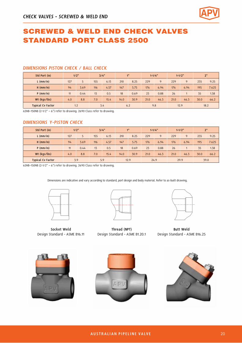
Std Port (in) 1/2” 3/4” 1” 1-1/4” 1-1/2” 2”
L (mm/in) 127 5 155 6.13 210 8.25 229 9 229 9 235 9.25
H (mm/in) 94 3.69 116 4.57 147 5.75 176 6.94 176 6.94 195 7.625
P (mm/in) 11 0.44 13 0.5 18 0.69 23 0.88 26 1 35 1.38
Wt (kgs/lbs) 4.0 8.8 7.0 15.4 14.0 30.9 21.0 46.3 21.0 46.3 30.0 66.2
Typical Cv Factor 1.2 3.4 6.2 9.8 12.9 18.2
DIMENSIONS PISTON CHECK / BALL CHECK
Std Port (in) 1/2” 3/4” 1” 1-1/4” 1-1/2” 2”
L (mm/in) 127 5 155 6.13 210 8.25 229 9 229 9 235 9.25
H (mm/in) 94 3.69 116 4.57 147 5.75 176 6.94 176 6.94 195 7.625
P (mm/in) 11 0.44 13 0.5 18 0.69 23 0.88 26 1 35 1.38
Wt (kgs/lbs) 4.0 8.8 7.0 15.4 14.0 30.9 21.0 46.3 21.0 46.3 30.0 66.2
Typical Cv Factor 3.9 5.9 12.9 24.9 29.9 39.0
DIMENSIONS Y-PISTON CHECK
Dimensions are indicative and vary according to standard, port design and body material. Refer to as-built drawing.
Socket WeldDesign Standard - ASME B16.11
Thread (NPT)Design Standard - ASME B1.20.1
Butt WeldDesign Standard - ASME B16.25
65NB~150NB (2-1/2” ~ 6”) refer to drawing. 2690 Class refer to drawing.
65NB~150NB (2-1/2” ~ 6”) refer to drawing. 2690 Class refer to drawing.
CHECK VALVES - SCREWED & WELD END
SCREWED & WELD END CHECK VALVESSTANDARD PORT CLASS 2500

6 AUSTRAL IAN P I P E L I N E VA LVE21
SymbolBonnet Joint
Class1/2”
(DN15)3/4”
(DN20)1”
(DN25)1-1/2” (DN40)
2” (DN50)
2-1/2” (DN65)
3” (DN80)
L (End to end)
SWB /PSB
1500 102 120 132 152 178 254 280
2500 114 132 152 178 203 254 280
W (Handwheel)
1500 150 170 200 280 320 360 360
2500 170 200 240 320 360 360 360
P (Port Dia.)
1500 12 16 20 32 40 48 59
2500 10 13 18 26 35 40 52
H (Height)
1500 216/227 243/256 280/294 366/385 450/473 510/536 510/536
2500 237/249 275/289 330/347 427/449 497/522 510/536 510/536
Wt (kg)
1500 5.7/6.0 6.8/7.2 8.2/8.7 17.2/18.1 34.0/35.7 38.0/39.9 49.0/51.5
2500 6.8/7.2 8.2/8.7 17.2/18.1 34.0/35.7 44.5/46.8 52.0/54.6 58.0/60.9
DIMENSIONS (MM) GATE PSB/SWB, CLASS 1500/2500
Seal Welded Bonnet (SWB) Pressure Sealed Bonnet (PSB)
No. Part Name
1 Body
2 Seat Ring
3 Wedge
4 Stem*
5 Bonnet
6 Packing**
7 Yoke
8 Gland
9 Gland Flange
10 Gland Bolt
11 Gland Nut
12 Yoke Sleeve
13 Thrust Washer
14 Handwheel
15 Nameplate
16 H/W Nut
17 Packing Washer
18 Bonnet Guide
19 Bonnet Nut
20 Gasket
21 Gasket Retainer
22 Set Screw
Thread (NPT)Design Standard - ASME B1.20.1
Butt WeldDesign Standard - ASME B16.25
Socket WeldDesign Standard - ASME B16.11
MATERIALS
100NB~300NB (4”~12”) refer to drawing. 2690 Class refer to drawing.
H (O
pen/
Clos
ed)
1
2
3
4
5
17
7
6
8
10
9
11
12
13
14
15
16
22
19
18
22
20
GATE VALVES - HIGH PRESSURE B16.34 DESIGN
* Stem Smoothness ≤ Ra 0.80 µm** Stuffing Box Finish ≤ Ra 3.2 µm
HIGH PRESSURE GATE VALVESSW, NPT, BW CLASS 1500/2500ASME B16.34 DESIGN ISO 15848-1 Class C02
Fugitive Emission CertifiedAPI 607-7th & ISO 10497
Firesafe Certified

AUSTRAL IAN P I P E L I N E VA LVE 22
Seal Welded Bonnet (SWB) Pressure Sealed Bonnet (PSB)
No. Part Name
1 Body
2 Disc Pad
3 Disc
4 Stem*
5 Bonnet
6 Packing**
7 Yoke
8 Gland
9 Gland Flange
10 Gland Bolt
11 Gland Nut
12 Yoke Bush
13 Handwheel
14 Nameplate
15 H/W Washer
16 H/W Nut
17 Packing Washer
18 Bonnet Guide
19 Bonnet Nut
20 Gasket
21 Gasket Retainer
22 Set Screw
MATERIALS
Thread (NPT)Design Standard - ASME B1.20.1
Butt WeldDesign Standard - ASME B16.25
Socket WeldDesign Standard - ASME B16.11
SymbolBonnet Joint
Class1/2”
(DN15)3/4”
(DN20)1”
(DN25)1-1/2” (DN40)
2” (DN50)
2-1/2” (DN65)
3” (DN80)
L (End to end)
SWB /PSB
1500 102 120 132 196 248 254 280
2500 114 132 152 216 260 254 280
W (Handwheel)
1500 150 170 200 280 320 360 360
2500 170 200 240 320 360 360 360
P (Port Dia.)
1500 12 16 20 32 40 48 59
2500 10 13 18 26 35 40 52
H (Height)
1500 212/223 240/252 277/291 372/391 455/478 510/536 510/536
2500 236/248 276/290 331/348 446/469 513/539 510/536 510/536
Wt (kg)
1500 5.7/6.0 6.8/7.2 8.2/8.7 17.2/18.1 34.0/35.7 38.0/38.9 49.0/51.5
2500 6.8/7.2 8.2/8.7 17.2/18.1 34.0/35.7 44.5/46.8 52.0/54.6 58.0/60.9
DIMENSIONS (MM) GLOBE PSB/SWB CLASS 1500/2500
H (O
pen/
Clos
ed)
100NB~300NB (4”~12”) refer to drawing. 2690 Class refer to drawing.
1
2
3
4
5
17
7
6
8
10
9
11
12
13
14
15
16
22
19
18
21
20
GLOBE VALVES - HIGH PRESSURE B16.34 DESIGN
HIGH PRESSURE GLOBE VALVESSW, NPT, BW, CLASS 1500/2500ASME B16.34 DESIGN
* Stem Smoothness ≤ Ra 0.80 µm** Stuffing Box Finish ≤ Ra 3.2 µm
6 AUSTRAL IAN P I P E L I N E VA LVE23
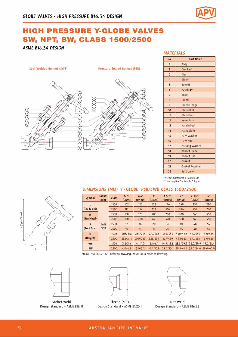
No. Part Name
1 Body
2 Disc Pad
3 Disc
4 Stem*
5 Bonnet
6 Packing**
7 Yoke
8 Gland
9 Gland Flange
10 Gland Bolt
11 Gland Nut
12 Yoke Bush
13 Handwheel
14 Nameplate
15 H/W Washer
16 H/W Nut
17 Packing Washer
18 Bonnet Guide
19 Bonnet Nut
20 Gasket
21 Gasket Retainer
22 Set Screw
MATERIALS
Thread (NPT)Design Standard - ASME B1.20.1
Butt WeldDesign Standard - ASME B16.25
Socket WeldDesign Standard - ASME B16.11
SymbolBonnet Joint
Class1/2”
(DN15)3/4”
(DN20)1”
(DN25)1-1/2” (DN40)
2” (DN50)
2-1/2” (DN65)
3” (DN80)
L (End to end)
SWB /PSB
1500 102 120 132 196 248 254 280
2500 114 132 152 216 286 254 280
W (Handwheel)
1500 150 170 200 280 320 360 360
2500 170 200 240 320 360 360 360
P (Port Dia.)
1500 12 16 20 32 40 48 59
2500 10 13 18 26 35 40 52
H (Height)
1500 208/218 233/245 270/283 366/384 440/462 510/535 510/535
2500 232/244 270/283 323/339 437/459 498/523 510/535 510/535
Wt (kg)
1500 3.2/3.4 4.1/4.3 6.1/6.4 14.9/15.6 28.5/29.9 38.0/39.9 49.0/51.4
2500 4.0/4.2 5.0/5.2 10.4/10.9 22.0/23.1 39.5/41.4 52.0/54.6 58.0/60.9
DIMENSIONS (MM) Y -GLOBE PSB/SWB CLASS 1500/2500
H (O
pen/
Clos
ed)
100NB~300NB (4”~12”) refer to drawing. 2690 Class refer to drawing.
Seal Welded Bonnet (SWB) Pressure Sealed Bonnet (PSB)
1
2
3
4
5
10
11
12
13
14
15
16
6
7
8
9
9
7
8
6
17
16
15
14
13
12
22
19
17
18
21
20
GLOBE VALVES - HIGH PRESSURE B16.34 DESIGN
HIGH PRESSURE Y-GLOBE VALVESSW, NPT, BW, CLASS 1500/2500ASME B16.34 DESIGN
* Stem Smoothness ≤ Ra 0.80 µm** Stuffing Box Finish ≤ Ra 3.2 µm

AUSTRAL IAN P I P E L I N E VA LVE 24
Symbol Bonnet Joint Class
1/2” (DN15)
3/4” (DN20)
1” (DN25)
1-1/2” (DN40)
2” (DN50)
2-1/2” (DN65)
3” (DN80)
L (End to end)
SWC
1500 102 120 132 196 248 254 280
2500 114 132 152 216 260 254 280
P (Port Dia.)
1500 12 16 20 32 40 48 59
2500 10 13 18 26 35 40 52
H (Height)
1500 73 84 92 130 153 206 235
2500 82 95 114 149 174 206 235
Wt (kg)
1500 2.4 3.0 4.2 10.5 19.5 28 36.0
2500 2.8 3.5 7.5 12.5 27.5 30.0 38.0
SymbolBonnet Joint
Class1/2”
(DN15)3/4”
(DN20)1”
(DN25)1-1/2” (DN40)
2” (DN50)
2-1/2” (DN65)
3” (DN80)
L (End to end)
SWC
1500 102 120 132 196 248 254 280
2500 114 132 152 216 286 254 280
P (Port Dia.)
1500 12 16 20 32 40 48 59
2500 10 13 18 26 35 40 52
H (Height)
1500 70 79 88 119 141 206 235
2500 80 93 108 146 167 216 235
Wt (kg)
1500 2.4 3.0 4.2 10.5 19.5 28 36.0
2500 2.8 3.5 7.5 12.5 27.5 30.0 38.0
SEAL WELDED COVER (SWC)
Thread (NPT)Design Standard - ASME B1.20.1
Butt WeldDesign Standard - ASME B16.25
Socket WeldDesign Standard - ASME B16.11
DIMENSIONS (MM) PISTON CHECK - 1500/2500 CLASS
DIMENSIONS (MM) Y-PISTON CHECK - 1500/2500 CLASS
100NB~300NB (4”~12”) refer to drawing. 2690 Class refer to drawing.
100NB~300NB (4”~12”) refer to drawing. 2690 Class refer to drawing.
Piston Check Y-Piston Check
3
2
4
1
CHECK VALVES - HIGH PRESSURE B16.34 DESIGN
HIGH PRESSURE PISTON CHECK VALVESSW, NPT, BW, CLASS 1500/2500ASME B16.34 DESIGN
No. Part Name
1 Body
2 Disc
3 Spring
4 Bonnet
MATERIALS

6 AUSTRAL IAN P I P E L I N E VA LVE28
1
2
3
4
5
7
8
9
10
11
12
13
14
15
16
17
18
19
20
21
22
23
24
SEAL WELD
SEAL WELDSEAL WELD
TACK WELD
6
GLOBE VALVES - BELLOW SEALED
BELLOW SEALED GLOBE VALVESW, NPT, BW 800 TO 2500 CLASS
• Inconelor321SSBellows - For longer life - Maximumcorrosionresistance• Flanged,screwedorweldedendconnections• Weldedorboltedbonnetdesign• Zerostemleakage - Eliminatesmedialoss - Satisfiesenvironmentalregulations• Zeromaintenance - Loweroperatingcosts/nodowntime• Threestemsealsforsafety - Metallicbellows - Graphitepacking - Backseatinopenposition
• Reducemonitoringcosts• Hardfacedseatingsurface - Stellite 6 for long life• Valvedesigned,manufacturedandtested - To ANSI B16.34/API 602 & 598• Additionalalloyandtrimsavailable• Forapplicationswhereleakageinto oroutofthevalveisunacceptable - Heattransferoil - Toxicfluids - Steam - Regulatedmedia
DESIGN FEATURES
OVERVIEWASME B16.34Design15NB - 50NB (1/2 - 2”) Bolted BonnetFlange Ends SW,NPT,BSPorButtweldendsavailable 150to2500ClassDesign API 602, BS 5352, MSS SP11, ANSI/ASME B16.34End Connections Socket Weld - ANSI/ASME B16.11 Thread - ANSI/ASME B1.20.1 Butt Weld - ANSI/ASME B16.25 Flange - ANSI/ASME B16.5Test and Inspection API 598 / BS 5146
No. Part Name
1 Body2 Disc3 Split Ring4 Disc Nut5 Gasket6 Bellows Holder Lower7 Bonnet Bolt8 Bellows9 Stem*10 Bonnet11 Bonnet Upper12 Guide Pin13 Gland Packing**14 Yoke15 Gland16 Gland Flange17 Gland Nut18 Gland Bolt19 Thrust Washer20 Yoke Sleeve21 Handwheel22 Handwheel Washer23 Name Plate24 Handwheel Nut
MATERIALS
* Stem Smoothness ≤ Ra 0.80 µm** Stuffing Box Smoothness ≤ Ra 3.2 µm

AUSTRAL IAN P I P E L I N E VA LVE 29
1
2
3
5
8
9
10
11
12
14
15
16
17
18
19
20
21
22
23
24
7
SEAL WELD
SEAL WELDSEAL WELD
TACK WELD
6
GATE VALVES - BELLOW SEALED
BELLOW SEALED GATE VALVESW, NPT, BW 800 TO 2500 CLASS
No. Part Name
1 Body2 Disc3 Split Ring5 Gasket6 Bellows Holder Lower7 Bonnet Bolt8 Bellows9 Stem10 Bonnet11 Bonnet Upper13 Gland Packing14 Yoke15 Gland16 Gland Flange17 Gland Nut18 Gland Bolt19 Thrust Washer20 Yoke Sleeve21 Handwheel22 Handwheel Washer23 Name Plate24 Handwheel Nut
• Inconelor321SSBellows - For longer life - Maximumcorrosionresistance• Flanged,screwedorweldedendconnections• Weldedorboltedbonnetdesign• Zerostemleakage - Eliminatesmedialoss - Satisfiesenvironmentalregulations• Zeromaintenance - Loweroperatingcosts/nodowntime• Threestemsealsforsafety - Metallicbellows - Graphitepacking - Backseatinopenposition
• Reducemonitoringcosts• Hardfacedseatingsurface - Stellite 6 for long life• Valvedesigned,manufacturedandtested - To ANSI B16.34/API 602 & 598• Additionalalloyandtrimsavailable• Forapplicationswhereleakageinto oroutofthevalveisunacceptable - Heattransferoil - Toxicfluids - Steam - Regulatedmedia
DESIGN FEATURES
MATERIALS
ISO 15848-1 Class CO2Fugitive Emission Certified
* Stem Smoothness ≤ Ra 0.80 µm** Stuffing Box Smoothness ≤ Ra 3.2 µm
OVERVIEWASME B16.34Design15NB - 50NB (1/2 - 2”) Bolted BonnetFlange Ends SW,NPT,BSPorButtweldendsavailable 150to2500ClassDesign API 602, BS 5352, MSS SP11, ANSI/ASME B16.34End Connections Socket Weld - ANSI/ASME B16.11 Thread - ANSI/ASME B1.20.1 Butt Weld - ANSI/ASME B16.25 Flange - ANSI/ASME B16.5Test and Inspection API 598 / BS 5146

6 AUSTRAL IAN P I P E L I N E VA LVE30
(Welded and Bolted Bonnet)
D
A
C
B
Butt Weld - ASME B16.25 Refer to drawing.
GATE VALVES - FLANGED
INTEGRAL FLANGED GATE VALVESBOLTED, WELDED & PRESSURE SEAL BONNETCLASS 150 TO 2500
DESIGN FEATURESIntegral FlangedOutsidescrewBolted bonnet & welded bonnetRegularbore&fullboreFlanging to ANSI B16.5.Otherflangesavailable.Alternativetrimmaterialsavailable.
STANDARDSConstruction API 602 & ANSI/ASME B16.34End Connections Socket Weld - ANSI/ASME B16.11 Thread - ANSI/ASME B1.20.1 Butt Weld - ANSI/ASME B16.25 Flanged - ANSI/ASME B16.5Inspection & Test API 598
Bolted Bonnet
A = Face to FaceB = Centre to topC = Wheel diameterD = Port Diameter
No. Part Name
1 Body
2 Disc
3 Stem*
4 Gasket
5 Bonnet
6 Bonnet Bolt
7 Gland Packing**
8 Gland Bolt
9 Gland
10 Gland Flange
11 Gland Nut
12 Yoke Bush
13 Handwheel
14 Name Plate
15 Handwheel Washer
16 Handwheel Nut
MATERIALS
* Stem Smoothness ≤ Ra 0.80 µm per API 602** Stuffing Box Finish ≤ Ra 3.2 µm per API 602
ISO 15848-1Fugitive Emission Certified
API 607-7th & ISO 10497Firesafe Certified
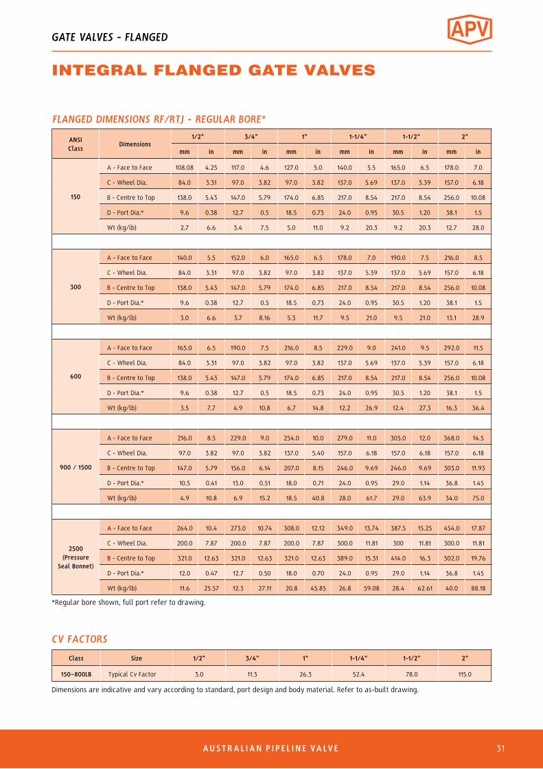
FLANGED DIMENSIONS RF/RTJ - REGULAR BORE*
ANSI Class
Dimensions1/2” 3/4” 1” 1-1/4” 1-1/2” 2”
mm in mm in mm in mm in mm in mm in
150
A - Face to Face 108.08 4.25 117.0 4.6 127.0 5.0 140.0 5.5 165.0 6.5 178.0 7.0
C - Wheel Dia. 84.0 3.31 97.0 3.82 97.0 3.82 137.0 5.69 137.0 5.39 157.0 6.18
B - Centre to Top 138.0 5.43 147.0 5.79 174.0 6.85 217.0 8.54 217.0 8.54 256.0 10.08
D - Port Dia.* 9.6 0.38 12.7 0.5 18.5 0.73 24.0 0.95 30.5 1.20 38.1 1.5
Wt (kg/lb) 2.7 6.6 3.4 7.5 5.0 11.0 9.2 20.3 9.2 20.3 12.7 28.0
300
A - Face to Face 140.0 5.5 152.0 6.0 165.0 6.5 178.0 7.0 190.0 7.5 216.0 8.5
C - Wheel Dia. 84.0 3.31 97.0 3.82 97.0 3.82 137.0 5.39 137.0 5.69 157.0 6.18
B - Centre to Top 138.0 5.43 147.0 5.79 174.0 6.85 217.0 8.54 217.0 8.54 256.0 10.08
D - Port Dia.* 9.6 0.38 12.7 0.5 18.5 0.73 24.0 0.95 30.5 1.20 38.1 1.5
Wt (kg/lb) 3.0 6.6 3.7 8.16 5.3 11.7 9.5 21.0 9.5 21.0 13.1 28.9
600
A - Face to Face 165.0 6.5 190.0 7.5 216.0 8.5 229.0 9.0 241.0 9.5 292.0 11.5
C - Wheel Dia. 84.0 3.31 97.0 3.82 97.0 3.82 137.0 5.69 137.0 5.39 157.0 6.18
B - Centre to Top 138.0 5.43 147.0 5.79 174.0 6.85 217.0 8.54 217.0 8.54 256.0 10.08
D - Port Dia.* 9.6 0.38 12.7 0.5 18.5 0.73 24.0 0.95 30.5 1.20 38.1 1.5
Wt (kg/lb) 3.5 7.7 4.9 10.8 6.7 14.8 12.2 26.9 12.4 27.3 16.3 36.4
900 / 1500
A - Face to Face 216.0 8.5 229.0 9.0 254.0 10.0 279.0 11.0 305.0 12.0 368.0 14.5
C - Wheel Dia. 97.0 3.82 97.0 3.82 137.0 5.40 157.0 6.18 157.0 6.18 157.0 6.18
B - Centre to Top 147.0 5.79 156.0 6.14 207.0 8.15 246.0 9.69 246.0 9.69 303.0 11.93
D - Port Dia.* 10.5 0.41 13.0 0.51 18.0 0.71 24.0 0.95 29.0 1.14 36.8 1.45
Wt (kg/lb) 4.9 10.8 6.9 15.2 18.5 40.8 28.0 61.7 29.0 63.9 34.0 75.0
2500 (Pressure
Seal Bonnet)
A - Face to Face 264.0 10.4 273.0 10.74 308.0 12.12 349.0 13.74 387.5 15.25 454.0 17.87
C - Wheel Dia. 200.0 7.87 200.0 7.87 200.0 7.87 300.0 11.81 300 11.81 300.0 11.81
B - Centre to Top 321.0 12.63 321.0 12.63 321.0 12.63 389.0 15.31 414.0 16.3 502.0 19.76
D - Port Dia.* 12.0 0.47 12.7 0.50 18.0 0.70 24.0 0.95 29.0 1.14 36.8 1.45
Wt (kg/lb) 11.6 25.57 12.3 27.11 20.8 45.85 26.8 59.08 28.4 62.61 40.0 88.18
Class Size 1/2” 3/4” 1” 1-1/4” 1-1/2” 2”
150~800LB Typical Cv Factor 3.0 11.3 26.3 52.4 78.0 115.0
CV FACTORS
Dimensions are indicative and vary according to standard, port design and body material. Refer to as-built drawing.
*Regular bore shown, full port refer to drawing.
GATE VALVES - FLANGED
INTEGRAL FLANGED GATE VALVES
AUSTRAL IAN P I P E L I N E VA LVE 31

6 AUSTRAL IAN P I P E L I N E VA LVE32
Butt Weld - ASME B16.25 Refer to drawing.
C
A
B
D
G
(Welded and Bolted Bonnet)
DESIGN FEATURESIntegralflanged.OutsidescrewBolted bonnet & welded bonnetRegularbore&fullboreFlanging to ANSI B16.5Otherflangesavailable.Alternativetrimmaterialsavailable.
GLOBE VALVES - FLANGED
INTEGRAL FLANGED GLOBE & SDNR VALVESBOLTED, WELDED & PRESSURE SEAL BONNETCLASS 150 TO 2500
Bolted Bonnet
No. Part Name
1 Body2 Disc3 Stem*4 Gasket5 Bonnet6 Bonnet Bolt7 Gland Packing**8 Gland Bolt9 Gland10 Gland Flange11 Gland Nut12 Yoke Bush13 Handwheel14 Name Plate15 Handwheel Washer16 Handwheel Nut
A = Face to FaceB = Centre to topC = Wheel diameterD = Port Diameter
MATERIALS
STANDARDSConstruction API 602 & ANSI/ASME B16.34End Connections Socket Weld - ANSI/ASME B16.11 Thread - ANSI/ASME B1.20.1 Butt Weld - ANSI/ASME B16.25 Flanged - ANSI/ASME B16.5Inspection & Test API 598
* Stem Smoothness ≤ Ra 0.80 µm per API 602** Stuffing Box Finish ≤ Ra 3.2 µm per API 602
ISO 15848-1Class C02Fugitive Emission Certified
API 607-7th & ISO 10497Firesafe Certified
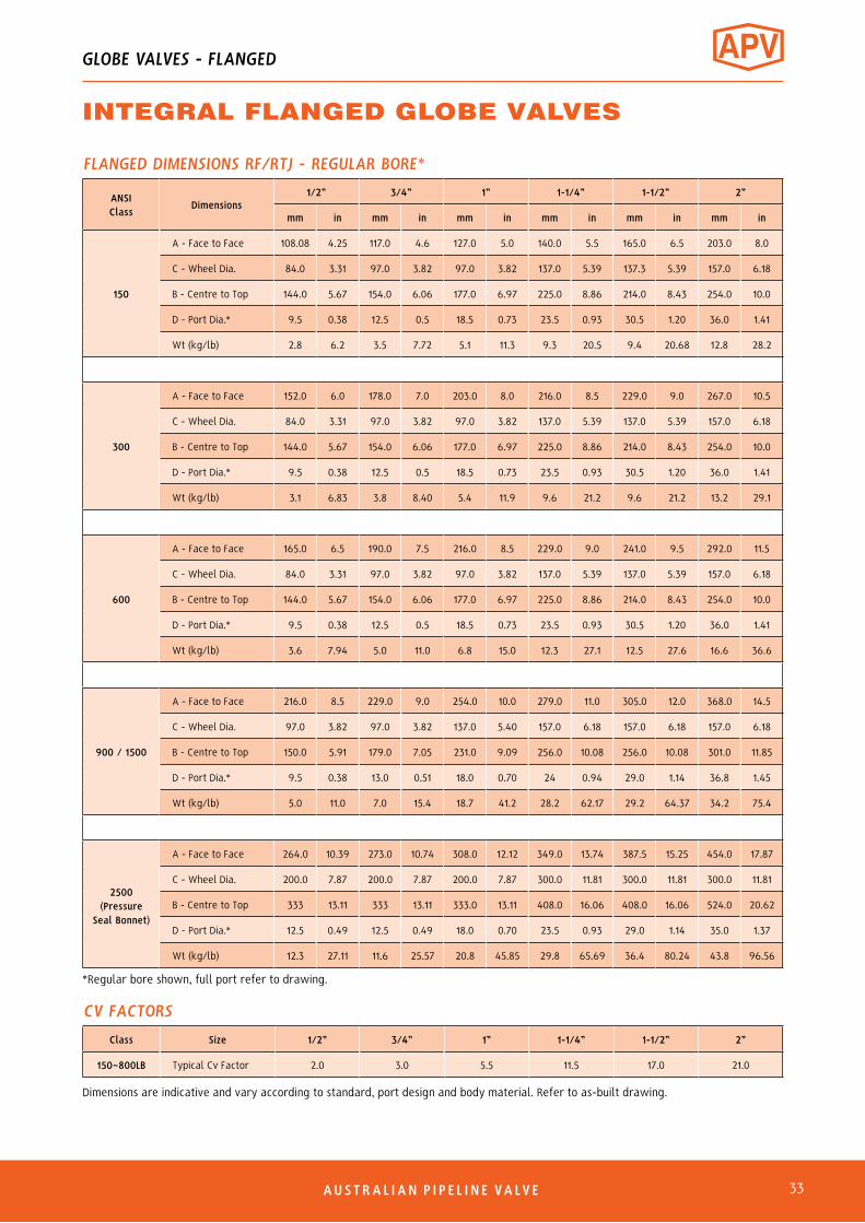
FLANGED DIMENSIONS RF/RTJ - REGULAR BORE*
ANSIClass
Dimensions1/2” 3/4” 1” 1-1/4” 1-1/2” 2”
mm in mm in mm in mm in mm in mm in
150
A - Face to Face 108.08 4.25 117.0 4.6 127.0 5.0 140.0 5.5 165.0 6.5 203.0 8.0
C - Wheel Dia. 84.0 3.31 97.0 3.82 97.0 3.82 137.0 5.39 137.3 5.39 157.0 6.18
B - Centre to Top 144.0 5.67 154.0 6.06 177.0 6.97 225.0 8.86 214.0 8.43 254.0 10.0
D - Port Dia.* 9.5 0.38 12.5 0.5 18.5 0.73 23.5 0.93 30.5 1.20 36.0 1.41
Wt (kg/lb) 2.8 6.2 3.5 7.72 5.1 11.3 9.3 20.5 9.4 20.68 12.8 28.2
300
A - Face to Face 152.0 6.0 178.0 7.0 203.0 8.0 216.0 8.5 229.0 9.0 267.0 10.5
C - Wheel Dia. 84.0 3.31 97.0 3.82 97.0 3.82 137.0 5.39 137.0 5.39 157.0 6.18
B - Centre to Top 144.0 5.67 154.0 6.06 177.0 6.97 225.0 8.86 214.0 8.43 254.0 10.0
D - Port Dia.* 9.5 0.38 12.5 0.5 18.5 0.73 23.5 0.93 30.5 1.20 36.0 1.41
Wt (kg/lb) 3.1 6.83 3.8 8.40 5.4 11.9 9.6 21.2 9.6 21.2 13.2 29.1
600
A - Face to Face 165.0 6.5 190.0 7.5 216.0 8.5 229.0 9.0 241.0 9.5 292.0 11.5
C - Wheel Dia. 84.0 3.31 97.0 3.82 97.0 3.82 137.0 5.39 137.0 5.39 157.0 6.18
B - Centre to Top 144.0 5.67 154.0 6.06 177.0 6.97 225.0 8.86 214.0 8.43 254.0 10.0
D - Port Dia.* 9.5 0.38 12.5 0.5 18.5 0.73 23.5 0.93 30.5 1.20 36.0 1.41
Wt (kg/lb) 3.6 7.94 5.0 11.0 6.8 15.0 12.3 27.1 12.5 27.6 16.6 36.6
900 / 1500
A - Face to Face 216.0 8.5 229.0 9.0 254.0 10.0 279.0 11.0 305.0 12.0 368.0 14.5
C - Wheel Dia. 97.0 3.82 97.0 3.82 137.0 5.40 157.0 6.18 157.0 6.18 157.0 6.18
B - Centre to Top 150.0 5.91 179.0 7.05 231.0 9.09 256.0 10.08 256.0 10.08 301.0 11.85
D - Port Dia.* 9.5 0.38 13.0 0.51 18.0 0.70 24 0.94 29.0 1.14 36.8 1.45
Wt (kg/lb) 5.0 11.0 7.0 15.4 18.7 41.2 28.2 62.17 29.2 64.37 34.2 75.4
2500 (Pressure
Seal Bonnet)
A - Face to Face 264.0 10.39 273.0 10.74 308.0 12.12 349.0 13.74 387.5 15.25 454.0 17.87
C - Wheel Dia. 200.0 7.87 200.0 7.87 200.0 7.87 300.0 11.81 300.0 11.81 300.0 11.81
B - Centre to Top 333 13.11 333 13.11 333.0 13.11 408.0 16.06 408.0 16.06 524.0 20.62
D - Port Dia.* 12.5 0.49 12.5 0.49 18.0 0.70 23.5 0.93 29.0 1.14 35.0 1.37
Wt (kg/lb) 12.3 27.11 11.6 25.57 20.8 45.85 29.8 65.69 36.4 80.24 43.8 96.56
Class Size 1/2” 3/4” 1” 1-1/4” 1-1/2” 2”
150~800LB Typical Cv Factor 2.0 3.0 5.5 11.5 17.0 21.0
CV FACTORS
Dimensions are indicative and vary according to standard, port design and body material. Refer to as-built drawing.
*Regular bore shown, full port refer to drawing.
GLOBE VALVES - FLANGED
INTEGRAL FLANGED GLOBE VALVES
AUSTRAL IAN P I P E L I N E VA LVE 33

6 AUSTRAL IAN P I P E L I N E VA LVE34
Bolted Bonnet
No. Part Name
1 Body
2 Disc
3 Gasket
4 Cover
5 Cover Bolt
6 Name Plate
7 Ball
8 Seat Ring
9 Disc
10 Retaining Ring
11 Hinge
12 Hinge Pin
13 Support
A = Face to FaceB = Centre to topD = Port Diameter
A
B
Butt Weld - ASME B16.25Refer to drawing.
MATERIALSDESIGN FEATURESBolted,weldedandpressuresealbonnet.Integralflanged.Regularportandfullport.Flanged to ANSI B16.5.Otherflangingavailable.Alternativetrimmaterialsavailable.Springcanbefittedforverticalservicetoballandpistontype.
Swing check Ball check
CHECK VALVES - FLANGED
INTEGRAL FLANGED CHECK VALVESBOLTED, WELDED & PRESSURE SEAL COVERCLASS 150 TO 2500
STANDARDSConstruction API 602, BS 5352 & ASME B16.34 (ISO 15761)End Connections Socket Weld - ANSI/ASME B16.11 Thread - ANSI/ASME B1.20.1 Butt Weld - ANSI/ASME B16.25 Flanged - ANSI/ASME B16.5Inspection & Test API 598

AUSTRAL IAN P I P E L I N E VA LVE 35
FLANGED DIMENSIONS - REGULAR BORE*
ANSI Class Size 1/2” 3/4” 1” 1-1/4” 1-1/2” 2”
150
A - Face to Face
Piston or Ball
mm in mm in mm in mm in mm in mm in
108.0 4.25 117.0 4.60 127.0 5.0 140.0 5.5 165.0 6.5 203.0 8.0
Swing Same as Piston or Ball Check Valve
B - Centre to Top 46.0 1.81 56.0 2.2 65.5 2.58 74.6 2.94 74.6 2.94 100.5 4.0
D - Port Dia.* 9.5 0.38 12.5 0.5 18.5 0.73 23.5 0.93 30.5 1.20 36.0 1.41
Wt (kg/lb) 2.2 4.8 3.0 6.6 4.3 9.5 7.7 17.0 8.3 18.3 13.0 28.7
300
A - Face to Face
Piston, Ball 152.0 60.0 178.0 7.0 203.0 8.0 216.0 8.5 229.0 9.0 267.0 10.5
Swing 140.0 5.5 152.0 6.0 165.0 6.5 229.0 9.0 241.0 9.5 267.0 10.5
B - Centre to Top 46.0 1.81 56.0 2.20 65.5 2.58 74.6 2.94 74.6 2.94 100.5 3.96
D - Port Dia.* 9.5 0.38 12.5 0.5 18.5 0.73 23.5 0.93 30.5 1.20 36.0 1.41
Wt (kg/lb) 3.3 7.3 5.1 11.2 7.5 16.5 9.9 21.8 13.0 28.7 19.0 41.9
600
A - Face to Face
Piston, Ball 165.0 6.5 190.0 7.5 216.0 8.5 229.0 9.0 241.0 9.5 292.0 11.5
Swing Same as Piston and Ball Check Valve
B - Centre to Top 46.0 1.81 56.0 2.20 65.5 2.58 74.6 2.94 74.6 2.94 100.5 2.96
D - Port Dia.* 9.5 0.38 12.5 0.5 18.5 0.73 23.5 0.93 30.5 1.20 36.0 1.41
Wt (kg/lb) 3.5 7.7 3.9 8.6 5.7 12.6 11.2 24.7 14.0 30.9 18.3 40.3
900/1500
A - Face to Face
Piston, Ball 216.0 8.5 229.0 9.0 254.0 10.0 279.0 11.0 305.0 12.0 368.0 14.5
Swing Same as Piston or Ball Check Valve
B - Centre to Top 62.0 2.44 68.1 2.68 84.6 3.33 100.5 3.96 102.0 4.02 124.6 4.91
D - Port Dia.* 9.5 0.38 12.5 0.5 18.5 0.73 23.5 0.93 30.5 1.20 36.0 1.41
Wt (kg/lb) 6.0 13.2 10.0 22.0 13.5 29.8 14.2 31.3 25.5 56.2 49.0 108.0
2500 (Pressure
Seal Bonnet)
A - Face to Face
Piston, Ball 264.0 10.39 273.0 10.74 308.0 12.12 - - 387.5 15.25 454.0 17.87
Swing Same as Piston or Ball Check Valve
B - Centre to Top 128.0 5.03 130.0 5.11 152.0 5.98 - - 188.0 7.40 190.0 7.48
D - Port Dia.* 12.5 0.49 12.5 0.49 18.0 0.71 - - 29.0 1.14 35.0 1.37
Wt (kg/lb) 14.3 31.52 16.0 35.27 23.6 52.02 - - 54.0 119.04 56.0 123.45
* Port diameter shown is for piston and ball check regular port. For swing and for full bore piston and ball check refer to drawing.
CV FACTORS - LIFT CHECK*
Class Size 1/2” 3/4” 1” 1-1/4” 1-1/2” 2”
150~800LB Typical Cv Factor 1.0 2.7 5.4 9.5 11.0 18.0
* Reduced Port
CV FACTORS - SWING CHECK*
Class Size 1/2” 3/4” 1” 1-1/4” 1-1/2” 2”
150~800LB Typical Cv Factor 6.0 11.3 26.3 63.0 78.0 115.0
* Reduced Port
CV FACTORS - Y-PISTON CHECK*
Class Size 1/2” 3/4” 1” 1-1/4” 1-1/2” 2”
150~800LB Typical Cv Factor 4.8 7.8 11.2 18.0 37.0 69.2
* Full Port
CHECK VALVES - FLANGED
INTEGRAL FLANGED CHECK VALVES

6 AUSTRAL IAN P I P E L I N E VA LVE36
No. Part Material
1 Body A105N2 Seat SS410+ST#63 Spreader SS4204 Parallel Disc A182 F6+ST#65 Stem* A182 F66 Gasket SS304+Graphite7 Bonnet A105N8 Bolt A193 B79 Packing** Graphite10 Pin SS41011 Gland SS41012 Gland Eyebolt A193 B713 Gland Flange A105N14 Nut A193 B715 Stem Nut SS41016 Handwheel Steel17 Washer A3+ZP18 Nut A194 2H19 Springs Inconel X75020 Location Pin A182 F621 Connection Pin A182 F6
STANDARDS COMPLIANCEBasic Design API 600, ANSI B16.34, BS 5157Face to Face Dimension ANSI B16.10End to End Dimension ANSI B16.10Flanged Ends ANSI 16.5B.W. Ends ANSI B16.25S.W. Ends ANSI B16.11Drilling to ANSI or BS/AS 2129 Table D to H or AS 4087 / AS 4331 / ISO 7005-1 PN 10 to 250 Pressure/Temperature ratings to ANSI B16.5
O.S.&Y.RisingStemFullPort,ExpandedParallelSlideGateValve,DoubleDisc,PressureSealorBoltedBonnet,Welded-inorThreadedSeatRings.Mechanicallyloadedseatingforlowandhigh pressuresealing.
Parallelslidedualloadeddiscsensuresuperiorshutoffandallowby-pass/bleedfitment(doubleblockandbleedrequiressoftseatinserts).
Pressure/temperaturechartsavailableonrequest.
AvailableinA105N,F22,F11,F5,316,304etc.
PRESSURE/TEMPERATURE A105N BODY
Class Cat No.Test Pressure to API 598 (PSIG) Working Pressure
Shell (Hydro)
Seat(Hydro)
Seat(Air)
CWPWOG
Saturated Steam(at 260°C)*
150 (AS/BST D to F) 150-P316SFXU-S 450 315 80 280 170
300 (AS/BST H to J) 300-P316SFXU-S 1125 815 80 720 600
600 600-P316SFXU-S 2225 1628 80 1440 1200
900 900-P316SFXU-S 3350 2442 80 2190 1800
1500 1500-P136SFXU-S 5626 4078 80 3600 3000
SeatingCode
Body SeatSurface Part
No. 3
Double DiscSurface Part
No. 4
StemPart No. 5
Back Seat(Stuffing Box)Part No. 10
X F6 F6 F6 F6U Stellite Stellite F6 F6XU Stellite F6 F6 F6P* F304 F304 F304 F304R* F316 F316 F316 F316M* Monel Monel Monel MonelN* Alloy 20 Alloy 20 Alloy 20 Alloy 20H* Hastelloy B Hastelloy B Hastelloy B Hastelloy B
TRIM MATERIAL CODES
* Add XU modifier to end of model suffix if stellite seat, if stellite seat & disc add U modifier to end.
Body Material Codes
None A105N
0 Special
5 A182 F5/F5a
6 A182 F11
8 A182 F304/304L
8M A182 F316/316L
9 A182 F22
Forinstallationinapplicationssuchasindustrial,miningandmechanicalservices.Suitableforsuper-heatedsteam,H.T.H.Wsteamcondensateandwater.
Thisdesignconsistsoftwodiscs,keptincontactwithparallelbodyseats,usingthelinepressureandsprungseatingactiontoeffecttightclosure.
Temperaturechangesinthelineareaccommodatedbytheexpandingdiscanddonotaffecttheactionofthevalve.Whenbeingopenedorclosed,thediscsslideacrosstheseatfaces,dislodginganyforeignmatter. Thevalveoperatingstemisoutsidescrewrisingthroughthehandwheel.
Thesevalvesaresuitableforfullboresteamuse,wherealowpressuredropacrossthevalveisrequired.Alsosuitableforwater,oil,gas,etc.
For superheated steam etc. consult chart. F11, F22, F5 chrome-moly available body for high temperature applications.
16 17 18
L
150~900 Class P316SF-WF
11
10
9
8
7
6
5
4
3
2
1
W
H12
13
14
15
STANDARD MATERIALS 316SF-WF
4
19
3 20
21
Wedge Spreader Rocker Die Parallel Disc Gate20
19
3
21
GATE VALVES - PARALLEL SLIDE
PARALLEL SLIDE GATE VALVECAT P316SF-WF CLASS 150-2500 (15~50NB)
Contact us for detailed drawing.* Stem Smoothness ≤ Ra 0.80 µm per API 602** Stuffing Box Finish ≤ Ra 3.2 µm per API 602

View our catalogues at www.australianpipelinevalve.com.au
AUSTRALIAN PIPELINE VALVE BRAND RANGE - CATALOGUES
APV FAMILY OF BRANDS RANGE - CATALOGUES
COMPLETE PRODUCT LINE
“Australian Pipeline Valve
produces isolation,
control and flow reversal
protection products for
severe and critical service
media in utility, steam,
pipelines, oil & gas
and process industries.
APV valves and pipeline
products form the most
competitive portfolio
in the market.”
Oilfield Products Valves & Wellheads
Gate, Globe & Check Valves - Forged Steel
Plug Valves Lubricated, Sleeved & Lined
Gate, Globe & Check Valves - Cast Steel
Diamond Gear Gearboxes
Flowturn Gate, Globe & Check Valves
Flowturn Instrument Valves
Flowturn Ball Valves Multiway & Deadman
Flowturn Strainers & Sight Glasses
Supercheck Wafer Check Valves
Superseal Butterfly Valves
Steamco Steam Valves
Superseal Industrial Ball Valves
TwinLok Tube Fittings Uniflo Check ValvesTorqturn Actuators
Ball Valves Floating & Trunnion Mounted
Ball Valves Floating Small Bore
Ball ValvesSpecial Service
Product Brochure
Contact us for your local stockist/distributor

6
QUALITY ASSURANCE AND CERTIFICATIONWe are continually improving all facets of quality assurance. Full metallurgical and test certificates arealways supplied for all pressure retaining parts, we also provide it on all major trim components.
We have endeavoured to provide a broad outline of our range and capabilities. Because we are continually developing new productsfor our customers this catalogue will, to some extent be incomplete. This catalogue is a general overview only, individual drawingsand data sheets can be furnished on request.
If you have any requirement in the field of valves, please contact us for a prompt response. Continuous development ofAustralian Pipeline Valve products may necessitate changes in the design or manufacturing processes. Australian Pipeline Valvereserves the right to effect any such changes without prior notice.
www.australianpipelinevalve.com.au
© Australian Pipeline Valve 1990 - 2021 Edition
LOCAL DISTRIBUTOR
A D E L A I D E • B R I S B A N E • P E R T H
Global Supply Line is distributor & stockist, supplying worldwide. Full stock list on line www.globalsupplyline.com.au
Contact email: [email protected]